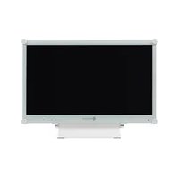
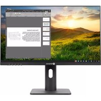
X-24EW - Screen AG Neovo - Free user manual and instructions
Find the device manual for free X-24EW AG Neovo in PDF.


| Product Type | LCD Monitor |
| Model Number | X-24EW |
| Screen Size | 24 inches (diagonal) |
| Resolution | 1920 x 1080 (Full HD) |
| Aspect Ratio | 16:9 |
| Response Time | 5 ms (typical) |
| Brightness | 300 cd/m² |
| Contrast Ratio | 1000:1 (static) |
| Viewing Angle | 178°/178° (horizontal/vertical) |
| Connectivity | VGA, DVI-D, HDMI |
| Power Consumption | ≤ 30 W (typical), Standby < 0.5 W |
| Power Supply | AC 100-240 V, 50/60 Hz |
| Dimensions (W x H x D) | 567 mm x 420 mm x 180 mm (with stand) |
| Weight | 5.0 kg (with stand) |
| VESA Mount Compatible | Yes (100 x 100 mm) |
| Features | Anti-glare screen, VGA cable included |
| Care and Cleaning | Wipe with a soft, dry cloth. Do not use solvents. |
| Safety Precautions | Use only the provided power cord. Do not expose to liquid or extreme temperatures. |
| Spare Parts & Repairability | Contact authorized service center. No user-serviceable parts inside. |
Frequently Asked Questions - X-24EW AG Neovo
User questions about X-24EW AG Neovo
0 question about this device. Answer the ones you know or ask your own.
Ask a new question about this device
Download the instructions for your Screen in PDF format for free! Find your manual X-24EW - AG Neovo and take your electronic device back in hand. On this page are published all the documents necessary for the use of your device. X-24EW by AG Neovo.
USER MANUAL X-24EW AG Neovo
Cautions When Using....7
Cleaning and Maintenance....7
Notice for the LCD Display 8
Chapter 1: Product Description
1.1 Package Contents 9
1.2 Wall Mounting Installation Preparation.... 10
1.2.1 Wall Mounting.... 10
1.2.2 Removing the Base Stand.... 10
1.3 LCD Display Overview 11
1.3.1 Front View and Keypad Buttons.... 11
1.3.2 Rear View....12
Chapter 2: Making Connections
2.1 Connecting the Power....13
2.2 Connecting Input Source Signals 14
2.2.1 Connecting a Computer 14
Using VGA Cables 14
Using DVI Cables....14
Using DisplayPort Cables 15
Connecting an Audio Device 15
2.2.2 Connecting a Video Device....16
Using HDMI Cables....16
Chapter 3: Using the LCD Display
3.1 Turning on the Power 17
3.2 Selecting the Input Source Signal 17
3.3 Adjusting the Volume....18
3.4 Locking the OSD Menu 18
3.5 Using Picture-in-Picture (PIP) 19
3.5.1 PIP Options 19
3.5.2 PIP Swap....20
3.6 Using Auto Adjustment Function 20
Chapter 4: On Screen Display Menu
4.1 Using the OSD Menu 21
4.2 OSD Menu Tree 23
TABLE OF CONTENTS
Chapter 5: Adjusting the LCD Display
5.1 BRIGHTNESS....26
5.2 COLOUR TEMP....28
5.3 IMAGE SETTING 29
5.4 ASPECT RATIO....32
5.5 PIP SETTING 33
5.6 ANTI-BURN-IN 35
5.7 OSD SETTING 36
5.8 AUDIO SETTING....37
5.9 SYSTEM....38
5.10 ECO SMART 40
5.11 INPUT SELECT 41
Chapter 6: Appendix
6.1 Warning Messages....42
6.2 Troubleshooting....43
6.3 Transporting the LCD Display 45
Chapter 7: Specifications
7.1 Display Specification 46
7.2 Display Dimensions 47
7.2.1 X-22E Dimensions....47
7.2.2 X-24E Dimensions.... 47
SAFETY INFORMATION

This FCC Class-B compliant digital device complies with the Interference-Causing Equipment Regulations of Canada.
FCC Declaimers
This device complies with Section 15 of the FCC listing. The operation procedures must meet the following conditions: (1) the device must not cause any damaging interference; and (2) this device must accept any received interference, including any unpredictable interference that may possibly occur.
Dear users,
This device has passed the Class B digital service regulations and complies with Section 15 of the FCC listing; these are intended to provide reasonable warranty against damaging interference for home use. This device will produce, use, and emit radio frequency energy; therefore, installation or use without following the instructions given may cause damaging interference to radio communication. Nonetheless, it is not possible to state with certainty that interference will occur from specific installations. If this device has caused damaging interference to radio or TV signals (simply turn the device on and off to check if such interference is caused by the device), we recommend that you fix the interference using the following methods
- Readjust the direction or location of the antenna.
- Increase the distance between this device and the receiver.
- Consult your local dealer or an experienced radio/TV technician.

Warning:
Making changes or modifications to the device without the permission from an authorized dealer may void the warranty of this device.
SAFETY INFORMATION
WEEE
Information for users applicable in European Union countries.

natural_image
Simple line drawing of a trash bin with no text or symbolsThe symbol on the product or its packaging signifies that this product has to be disposed separately from ordinary household wastes at its end of life. Please kindly be aware that this is your responsibility to dispose electronic equipment at recycling centers so as to help conserve natural resources. Each country in the European Union should have its collection centers for electrical and electronic equipment recycling. For information about your recycling drop off area, please contact your local related electrical and electronic equipment waste management authority or the retailer where you bought the product.
PRECAUTIONS


Symbols used in this manual
 | This icon indicates the existence of a potential hazard that could result in personal injury or damage to the product. |
 | This icon indicates important operating and servicing information. |
Notice
- Read this User Manual carefully before using the LCD display and keep it for future reference.
- The product specifications and other information provided in this User Manual are for reference onl. All information is subject to change without notice. Updated content can be downloaded from our web site at http://www.agneovo.com.
• To register online, go to http://www.agneovo.com. - To protect your rights as a consumer, do not remove any stickers from the LCD display. Doing so may affect the determination of the warranty period.
Cautions When Setting Up
 | Do not place the LCD display near heat sources, such as a heater, exhaust vent, or in direct sunlight. |
 | Do not cover or block the ventilation holes in the housing. |
 | Place the LCD display on a stable area. Do not place the LCD display where it may subject to vibration or shock. |
 | Place the LCD display in a well-ventilated area. |
 | Do not place the LCD display outdoors. |
 | Do not place the LCD display in a dusty or humid environment. |
 | Do not spill liquid or insert sharp objects into the LCD display through the ventilation holes. Doing so may cause accidental fire, electric shock or damage the LCD displa . |
PRECAUTIONS
Cautions When Using
 | Use only the power cord supplied with the LCD display. |
 | The power outlet should be installed near the LCD display and be easily accessible. |
 | If an extension cord is used with the LCD display, ensure that the total current consumption plugged into the power outlet does not exceed the ampere rating. |
 | Do not allow anything to rest on the power cord. Do not place the LCD display where the power cord may be stepped on. |
 | If the LCD display will not be used for an indefinite period of time, unplug the power cord from the power outlet. |
 | To disconnect the power cord, grasp and pull by the plug head. Do not tug on the cord; doing so may cause fire or electric shock |
 | Do not unplug or touch the power cord with wet hands. |
Cleaning and Maintenance
 | The LCD display comes with NeoVTM Optical Glass. Use a soft cloth lightly moistened with a mild detergent solution to clean the glass surface and the housing. |
 | Do not rub or tap the surface of the glass with sharp or abrasive items such as a pen or screwdriver. This may result in scratching the surface of the glass. |
 | Do not attempt to service the LCD display yourself, refer to qualified service personnel. Opening or removing the covers may expose you to dangerous voltage or other risks. |

Warning:

Unplug the power cord from the power outlet and refer to qualified service
personnel under the following conditions:
When the power cord is damaged.
If the LCD display has been dropped or the housing has been damaged.
If the LCD display emits smoke or a distinct odor.

Warning:

Ceiling mount or mount on any other horizontal surface overhead are not advisable.
Installation in contravention of the instructions may result in undesirable consequences, particularly hurting people and damaging property. Users who have already mounted the display on the ceiling or any other horizontal surface overhead are strongly advised to contact AG Neovo for consultations and solutions to help ensure a most pleasurable and fulfilling display experience.
Notice for the LCD Display
In order to maintain the stable luminous performance, it is recommended to use low brightness setting.
Due to the lifespan of the lamp, it is normal that the brightness quality of the LCD display may decrease with time.
When static images are displayed for long periods of time, the image may cause an imprint on the LCD display. This is called image retention or burn-in.
To prevent image retention, do any of the following:
- Set the LCD display to turn off after a few minutes of being idle.
- Use a screen saver that has moving graphics or a blank white image.
- Switch desktop backgrounds regularly.
- Adjust the LCD display to low brightness settings.
- Turn off the LCD display when the system is not in use.
Things to do when the LCD display shows image retention:
- Turn off the LCD display for extended periods of time. It can be several hours or several days.
- Use a screen saver and run it for extended periods of time.
- Use a black and white image and run it for extended periods of time.
When the LCD display is moved from one room to another or there is a sudden change from low to high ambient temperature, dew condensation may form on or inside the glass surface. When this happens, do not turn on the LCD display until the dew disappears.
Due to humid weather conditions, it is normal for mist to form inside the glass surface of the LCD display. The mist will disappear after a few days or as soon as the weather stabilizes.
There are millions of micro transistors inside the LCD display. It is normal for a few transistors to be damaged and to produce spots. This is acceptable and is not considered a failure.
CHAPTER 1: PRODUCT DESCRIPTION
1.1 Package Contents
When unpacking, check if the following items are included in the package. If any of them is missing or damaged, contact your dealer.

LCD Display
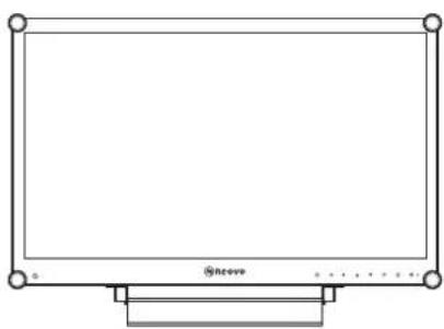
natural_image
Simple line drawing of a rectangular frame with rounded corners and a base, no text or symbols present.
User Manual


Power adapter
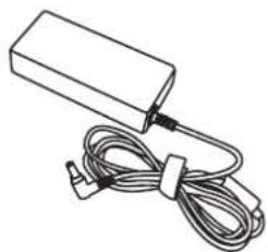
natural_image
Line drawing of a rectangular electronic device with a coiled cable and connector (no text or symbols)
Power cord
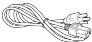
natural_image
Line drawing of a cord with two connected power plugs (no text or symbols)
VGA cable


Audio cable

Note:
Must use only the supplied power adapter:
♦ Lite-on Technology Corporation Model no.: PA-1041-8
Rating: 12V/3.33A
Note:
The pictures are for reference only. Actual items may vary upon shipment.
PRODUCT DESCRIPTION
1.2 Wall Mounting Installation Preparation
1.2.1 Wall Mounting
1 Remove the base stand.
See procedures below.
2 Wall mount the LCD display.
Screw the mounting bracket to the VESA holes at the rear of the LCD display.

1.2.2 Removing the Base Stand
1 Lay the LCD display face down on a flat even surface.
2 Remove the four screws securing the base stand from the LCD display.
3 Detach the base stand.

Note:
To protect the glass panel, place a towel or soft cloth before laying the LCD display down.

Warning:

Ceiling mount or mount on any other horizontal surface overhead are not advisable.
Installation in contravention of the instructions may result in undesirable consequences, particularly hurting people and damaging property. Users who have already mounted the display on the ceiling or any other horizontal surface overhead are strongly advised to contact AG Neovo for consultations and solutions to help ensure a most pleasurable and fulfilling display experience.
Note:
Take measures to prevent the LCD display from falling down and lessen possible injury and damage to the display in case of earthquakes or other disasters.
Use only the 75 x 75 mm and 100 x 100 mm wall mount kit recommended by AG Neovo.
- Secure the LCD display on a solid wall strong enough to bear its weight.
1.3 LCD Display Overview
1.3.1 Front View and Keypad Buttons

1 Display screen
The LCD display screen is protected by NeoV™ Optical Glass.
2 AUTO
Hot Key: For VGA input signal source, press to perform auto adjustment.
- During OSD menu selection, press to close the OSD menu or exit a submenu.
3 LEFT
Hot Key: Volume Up
- Press to display the volume screen. Then press again to decrease the volume.
- During OSD menu selection, press to adjust the settings.
4 RIGHT
Hot Key: Volume Down
- Press to display the volume screen. Then press again to increase the volume.
- During OSD menu selection, press to select an option and adjust the settings.
5 UP
Hot Key: PIP Select
- Press repeatedly to select PIP option.
- During OSD menu selection, press to move up a menu or submenu.
6 DOWN
Hot Key: Aspect Ratio
- When PIP is on, press to SWAP the PIP main and sub picture.
- During OSD menu selection, press to move up a menu or submenu.
7 MENU
- Press to display the OSD menu.
- Press again to hide the OSD menu.
8 SOURCE
- Press to select the input signal source.
9 POWER / LED indicator
- Press to turn the power on or off. Green - Power on Amber - Standby mode Off - Power off
1.3.2 Rear View
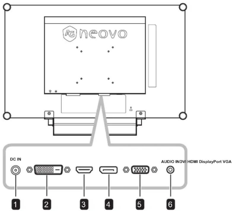
1 DC power input
Use to connect the power cord.
2 DVI connector
Use to connect a PC using a DVI cable for digital input signal.
3 HDMI connector
Use to connect an input device using an HDMI cable for digital input signal.
4 DisplayPort connector
Use to connect a PC using a DisplayPort cable for digital input signal.
5 VGA connector
Use to connect a PC using a VGA cable for analogue input signal.
6 Audio port
Use to connect an audio cable for the PC's audio input.
CHAPTER 2: MAKING CONNECTIONS
2.1 Connecting the Power
1 Connect the power cord to the power adapter.
2 Connect the power adapter to the DC power input at the rear of the LCD display.
3 Connect the power cord plug to a power outlet or a power supply.

Caution:
Make sure that the LCD display is not connected to the power outlet before making any connections. Connecting cables while the power is ON may cause electric shock or personal injury.

Caution:
When unplugging the power cord, hold the power cord by the plug head. Never pull by the cord.
MAKING CONNECTIONS
2.2 Connecting Input Source Signals
2.2.1 Connecting a Computer
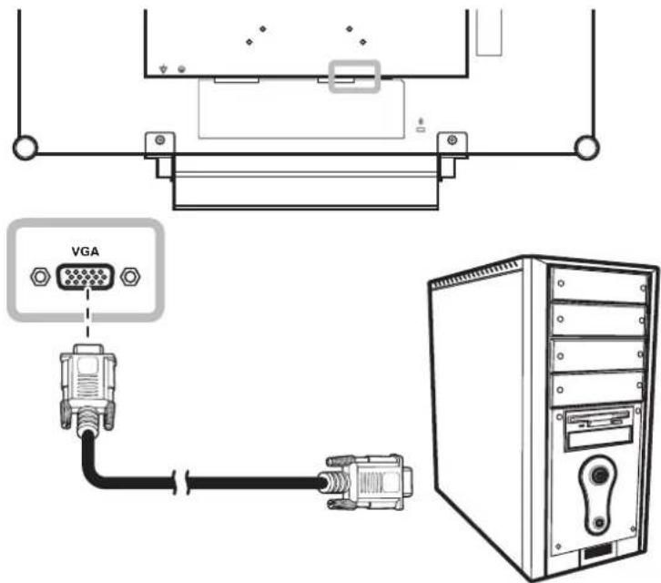
Using VGA Cables
Connect one end of a D-sub cable to the VGA connector of the LCD display and the other end to the D-sub connector of the computer.
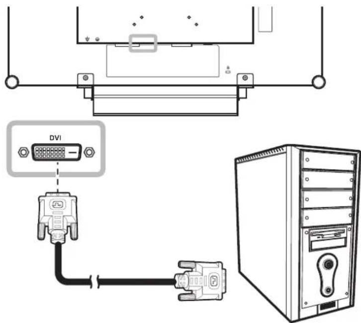
Using DVI Cables
Connect one end of a DVI cable to the DVI connector of the LCD display and the other end to the DVI connector of the computer.
MAKING CONNECTIONS
Using DisplayPort Cables
Connect one end of a DisplayPort cable to the DisplayPort connector of the LCD display and the other end to the DisplayPort connector of the computer.

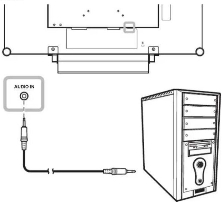
Connecting an Audio Device
Connect one end of an audio cable to the audio port at the rear of the LCD display and the other end to the audio out port of the computer.
MAKING CONNECTIONS
2.2.2 Connecting a Video Device
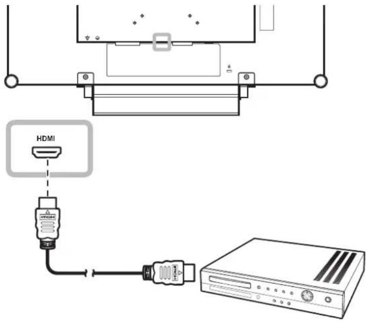
Using HDMI Cables
Connect one end of an HDMI cable to the HDMI connector of the LCD display and the other end to the HDMI connector of your device.
CHAPTER 3: USING THE LCD DISPLAY
3.1 Turning on the Power
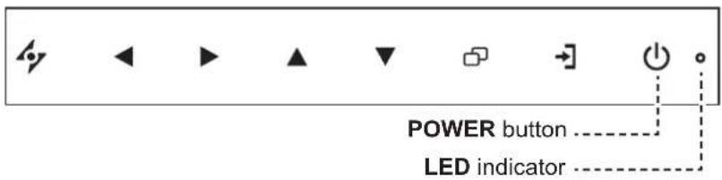
1 Plug the power cord to a power outlet or power supply.
2 Touch the POWER button to turn the LCD display on.
The LED indicator turns GREEN.
When the LCD display is turned on, touch the POWER button to turn off the LCD display.
The LED indicator turns off.
3.2 Selecting the Input Source Signal
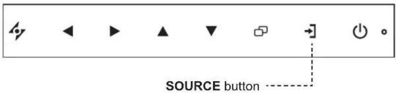
1 Touch the button to call out the input source menu.
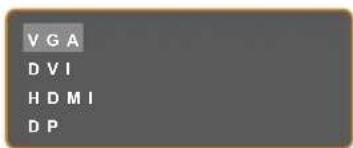
2 Touch the ▲ or ▼ button to highlight an input source.
3 Touch the ▶ button to select the input source.
Note:
The LCD display still consumes power as long as the power cord is connected to the power outlet. Disconnect the power cord to completely cut off power.
Notes:
This function works only if SOURCE DETECT is set to MANUAL. Refer to page 38.
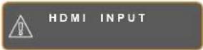
- After selecting an input source signal, the input source signal message appears on the screen briefl.
For example, HDMI is selected the following message is displayed.
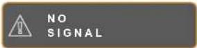
If the selected input source signal is not connected to the LCD display or is turned off, the no signal message is displayed on the screen.
If the resolution or the graphics card of the connected computer is set too high, the input out of range message is displayed.

3.3 Adjusting the Volume

1 Touch the ◀ or ▶ button to call out the volume bar.

2 Touch the ▶ button to increase volume or the ◀ button to decrease volume.
To mute the audio, set the volume to 0.
3.4 Locking the OSD Menu
Lock the OSD menu to protect the LCD display from unauthorised users or from accidentally pressing the keypad.
To lock the OSD, press and hold the keypad buttons listed below for at least 5 seconds or until the

OSD LOCK OUT
message appears.
When the OSD is locked, all keypad buttons are inactivated.
| Type of OSD Lock Lock Operation Unlock Operation | ||
| Lock all buttons | Touch and hold the ▶, ▲, and ▼buttons for 5 seconds. | Touch and hold the ▶, ▲, and ▼buttons for 5 seconds or until the OSD menu appears. |
| Lock all buttons except the POWER button. | Touch and hold the ◀, ▲, and ▼buttons for 5 seconds. | Touch and hold the ◀, ▲, and ▼buttons for 5 seconds or until the OSD menu appears. |
3.5 Using Picture-in-Picture (PIP)
The Picture-in-Picture (PIP) feature allows viewing of more than one input source signal on the LCD display.
3.5.1 PIP Options
Touch the ▲ button repeatedly to enable and scroll among the PIP options. Options are as follows:
- PIP On: The sub source signal is displayed within the main source signal.
- PBP (Picture-by-Picture): The main source and the sub source signals are displayed side by side with equal display size.
- PIP Off: PIP function is disabled, only the main source signal is displayed.

flowchart
graph TD
    A["PIP On"] --> B["PBP"]
    B --> C["PIP Off"]
Note:
- The main source and sub source signals can be set in PIP Setting, see page 33.
Some input source signal combinations do not support PIP. See PIP Compatibility table on page 34.
USING THE LCD DISPLAY
3.5.2 PIP Swap
The main and the sub source signals set in PIP Setting can be easily swapped using the keypad.
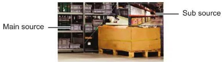
Touch the ▼ button to swap the main source and the sub source signals. See illustration below.

3.6 Using Auto Adjustment Function
Auto Adjustment function automatically tunes the LCD display to its optimal setting, including horizontal position, vertical position, clock, and phase.
Touch the 47 button to perform auto adjustment.
The message auto adjusting is displayed on the screen.

During auto adjustment, the screen will slightly shake for a few seconds.
When the message disappears, auto adjustment is completed.
Note:
◆ PIP Swap can only be executed if PIP is enabled, see page 34.
Note:
- Auto Adjustment function is available only during VGA input signals.
It is recommended to use the auto adjustment function when using the LCD display for the first time or after a resolution or frequency change.
CHAPTER 4: ON SCREEN DISPLAY MENU
4.1 Using the OSD Menu
| Operation | |
| 1 Display the main menu screen. | Touch |
 | |
| 2 Select the menu. | 1 Touch the ▲ or ▼ button.2 Touch the ▶ button to enter the submenu. |
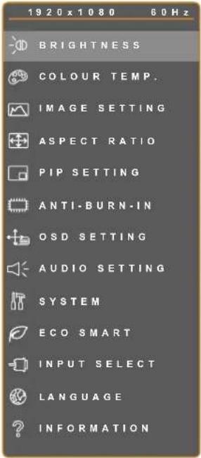 | |
ON SCREEN DISPLAY MENU
| Operation | |
3 Select the submenu item. The highlighted item with an orange arrow indicates the active submenu. The highlighted item with an orange arrow indicates the active submenu. | Touch the ▲ or ▼ button. |
| 4 Adjust the settings. | Touch the ◀ or ▶ button. |
| 5 Exit the submenu. | Touch ▼ or □ return to the previous menu. |
| 6 Close the OSD window. | Touch ▼ or □ again. |
When settings are modified, all changes are saved when the user does the following
• Proceeds to the another menu.
- Exits the OSD menu.
- Waits for the OSD menu to disappear.
Note: Availability of some menu items depend on the input source signal. If the menu is not available, it is disabled and grayed out.
ON SCREEN DISPLAY MENU
4.2 OSD Menu Tree
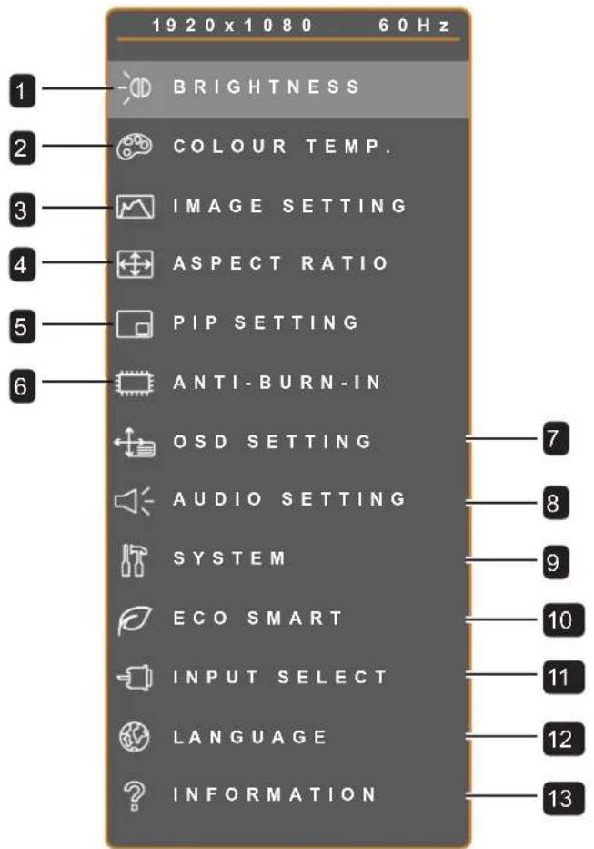
| Main Menu Submenu Remarks | ||
| 1. BRIGHTNESS • BRIGHTNESS | CONTRASTBACKLIGHTBLACK LEVEL | See page 26. |
| 2. COLOUR TEMP. • COLOUR TEMP. | AUTO COLOUR | See page 28. |
| 3. IMAGE SETTING • SHARPNESS | SATURATIONTINTGAMMACOLOUR RANGENOISE REDUCTIONPICTURE MODEH. POSITIONV. POSITIONPHASECLOCK | See page 29. |
ON SCREEN DISPLAY MENU
| Main Menu Submenu Remarks | ||
| 4. ASPECT RATIO • ASPECT RATIO | H. ZOOMV. ZOOMOVERSCAN | See page 32. |
| 5. PIP SETTING • PIP | MAIN SOURCESUB SOURCESUB PICTURE SIZESUB PIC. POS.SWAP | See page 33. |
| 6. ANTI-BURN-IN • ENABLE | INTERVAL (HOURS)MODE | See page 35. |
| 7. OSD SETTING • TRANSPARENCY | OSD H. POSITIONOSD V. POSITIONOSD TIMER | See page 36. |
| 8. AUDIO SETTING • VOLUME | AUDIOSOURCE | See page 37. |
| 9. SYSTEM • POWER SAVING | SOURCE DETECTMODEDDC/ICDCRBLUE SCREENSIGNAL INFOHDMI CECLOGORECALL | See page 38. |
| 10. ECO SMART • ENABLE | MODELEVEL | See page 40. |
| 11. INPUT SELECT • VGA | DVICHDMIDP | See page 41. |
ON SCREEN DISPLAY MENU
Main Menu Submenu Remarks
| 12. LANGUAGE Select the OSD language | EN / FR / DE / ES / IT / PY / RO / PL / CS / NL / 簡中 / 繁中 | |
| 13. INFORMATION Displays settings in | information such as Input,Resolution, Horizontal Frequency, Vertical Frequency, Timing Mode, and Firmware Version. |
CHAPTER 5: ADJUSTING THE LCD DISPLAY
5.1 BRIGHTNESS

- Touch to call out the OSD window.
- Select BRIGHTNESS menu, then touch the ▶ button.
- Touch the ▲ or ▼ button to select an option.
| Item Function Operation Range | |||
| BRIGHTNESS | Adjusts the luminance of the screen image. | Touch the ◀ or ▶ button to adjust the value. | 0 to 100 |
| CONTRAST | Adjusts the difference between the black level and the white level. | ||
| BACKLIGHT | Adjusts the luminance of the screen image.Note: This menu option is not available if the ECO SMART function is enabled. | ||
| BLACK LEVEL | Adjusts the black level of the screen image. Low brightness setting makes black colour darker. | ||
See comparison illustrations on page 27.
ADJUSTING THE LCD DISPLAY
Original Setting High Setting Low Setting
ADJUSTING THE LCD DISPLAY
5.2 COLOUR TEMP.
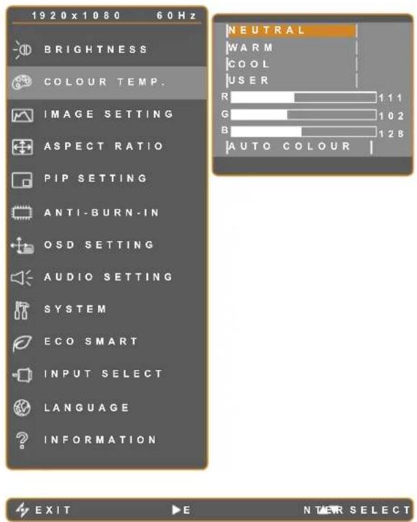
- Touch to call out the OSD window.
- Select COLOUR TEMP. menu, then touch the ▶ button.
- Touch the ▲ or ▼ button to select an option.
| Item Function Operation Range | |||
| COLOUR TEMP. | Provides several colour settings. | Touch the ◀ or ▶ button to select the setting. | NEUTRALWARMCOOLUSER |
| Colour setting can be set to:NEUTRAL - commonly used for normal lighting conditions.WARM - Applies a reddish tint for warmer colours.COOL - Applies a bluish tint for cooler colours.USER - This allows users to set the colour temperature by adjusting the R, G, B settings according to one's preference.1 Select USER, and touch the ▶ button.2 Touch the ▲ or ▼ button to select the colour you want to adjust.3 Touch the ◀ or ▶ button to adjust the values between 0 ~ 255.Note: Activate RECALL to return the colour to its default setting. | |||
| AUTO COLOUR | Operates the white balance and automatically adjusts the colour settings.Note: This menu option is only available if the input source is VGA. | Touch the ▶ button to execute the function. | - |
ADJUSTING THE LCD DISPLAY
5.3 IMAGE SETTING

- Touch to call out the OSD window.
- Select IMAGE SETTING menu, then touch the ▶ button.
- Touch the ▲ or ▼ button to select an option.
| Item Function Operation Range | ||||
| SHARPNESS | Adjusts the clarity and focus of the screen image. | Touch the ◀ or ▶ button to adjust the value. | 0 to 100 | |
| SATURATION Adjusts the colour saturation. | ||||
| TINT Adjusts the colour tint. | ||||
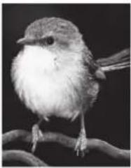
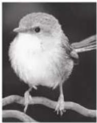
| GAMMA | Adjusts the non-linear setting for picture luminance and contrast. | Touch the ◀ or ▶ button to select the setting. | 2.2S2.42.0 | |
 |  | 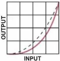 | 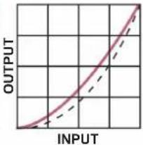 | |
| Display Gamma 2.2 | Display Gamma S | Display Gamma 2.4 | Display Gamma 2.0 | |
 |  |  |  | |
ADJUSTING THE LCD DISPLAY
| Item Function Operation Range | |||
| COLOUR RANGE | Adjusts black and white levels for video. Note: This menu option is only available if the input source is HDMI. | Touch the ◀ or ► button to select the setting. | FULL LIMIT |
Signal source from PC - PC signal at a full range (Grayscale 0-255) state:  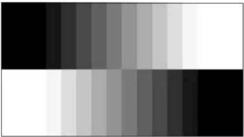 Monitor OSD colour range: Full *Please select Monitor OSD colour range: Limit Monitor OSD colour range: Full *Please select Monitor OSD colour range: Limit | |||
Signal source from Video - Video signal at a limited range (Grayscale 16-235) state:  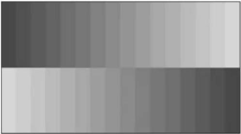 Monitor OSD colour range: Limit *Please select Monitor OSD colour range: Full Monitor OSD colour range: Limit *Please select Monitor OSD colour range: Full | |||
| NOISE REDUCTION | Adjusts the noise reduction to help remove noise from images. This helps produce clearer and crisper images. | Touch the ◀ or ► button to select the setting. | OFF LOW MID HIGH |
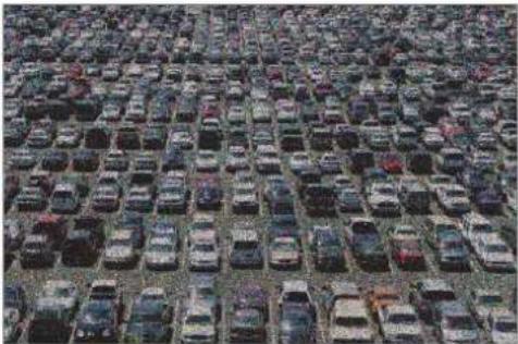  Noise Reduction Off Noise Reduction On Noise Reduction Off Noise Reduction On | |||
| PICTURE MODE | Selects a predefined picture mode setting. | Touch the ◀ or ► button to select the setting. | STANDARD VIVID CINEMA |
| H. POSITION(Horizontal Position) | Moves the screen image to the left or right. | ||
| V. POSITION(Vertical Position) | Moves the screen image up or down. | ||
| PHASE | Adjusts the phase timing to synchronise with the video signal. Note: This menu option is only available if the input source is VGA. | Touch the ◀ or ▶ button to adjust the value. | 0 to 100 |
| CLOCK | Adjusts the frequency timing to synchronise with the video signal. Note: This menu option is only available if the input source is VGA. | ||
ADJUSTING THE LCD DISPLAY
5.4 ASPECT RATIO
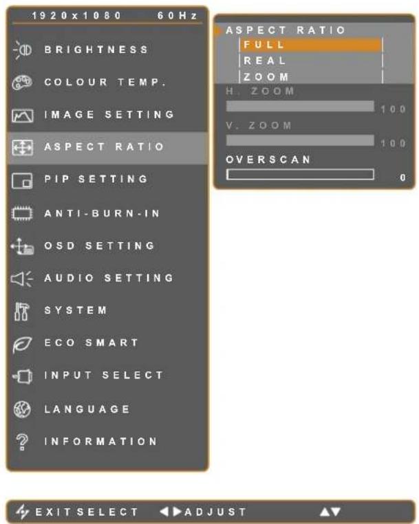
- Touch to call out the OSD window.
- Select ASPECT RATIO menu, then touch the ▶ button.
- Touch the ▲ or ▼ button to select an option.
| Item Function Operation Range | |||
| ASPECT RATIO | Adjusts the aspect ratio of the screen image. | Touch the ◀ or ► button to select the setting. | FULL REAL ZOOM |
| H. ZOOM (Horizontal Zoom) | Adjusts the horizontal zoom.Note: This menu option is only available if the ASPECT RATIO setting is to ZOOM. | Touch the ◀ or ► button to adjust the value. | 0 to 100 |
| V. ZOOM (Vertical Zoom) | Adjusts the vertical zoom.Note: This menu option is only available if the ASPECT RATIO setting is to ZOOM. | ||
| OVERSCAN | Adjusts the overscan setting to fix the cut-off screen edges. | 0 to 15 | |
ADJUSTING THE LCD DISPLAY
5.5 PIP SETTING


- Touch to call out the OSD window.
- Select PIP SETTING menu, then touch the ▶ button.
- Touch the ▲ or ▼ button to select an option.
| Item Function | Operation | Range | |
| PIP | Allows you to select the PIP setting or disable PIP. | Touch the ◀ or ► button to select the value. | OFFPIPPBP |
| PIP can be set to:OFF - Disables PIP.PIP - The sub source image is within the main source image.PBP - The main source and sub source images are displayed side by side. | |||
| MAIN SOURCE | Allows you to select the main source signal. | Touch the ◀ or ► button to select the setting. | VGADVIHDMIDP |
| SUB SOURCE | Allows you to select the sub source signal. | ||
ADJUSTING THE LCD DISPLAY
Note: Any input signal may be set as the main or the sub source signal. However, some input signals are not supported to be paired together as the main and the sub source signals.
Refer to the following table for compatibility options.
Table 5.1 PIP Compatibility Table
| Input Source | Main Source | ||||
| VGA DVI HDMI DP | |||||
| Sub Source | VGA X O O O | ||||
| DVI O X O O | |||||
| HDMI O O X O | |||||
| DP O O O X | |||||
| Item Function Operation Range | |||
| SUB PICTURE SIZE(Sub Picture Size) | Allows you to select the size of the sub source image.Note: This menu option is only available if thePIPsetting is toPIP. | Touch the◀ or ▶ button to select the setting. | 123 |
| The size of the sub source image can be set to:1 - Small image size.2 - Medium image size.3 - Large image size. | |||
| SUB PIC. POS.(Sub Picture Position) | Allows you to select the position of the sub source image.Note: This menu option is only available if thePIPsetting is toPIP | Touch the◀ or ▶ button to select the setting. | L+UR+UL+DR+D |
| The position of the sub source image can be set to:L+U - Sets the image on the upper left corner of the screen.R+U - Sets the image on the upper right corner of the screen.L+D - Sets the image on the lower left corner of the screen.R+D - Sets the image on the lower right corner of the screen. | |||
| SWAP | Swaps the main source and sub source signals. | Touch the▶ button to execute the function. | - |
ADJUSTING THE LCD DISPLAY
5.6 ANTI-BURN-IN

- Touch to call out the OSD window.
- Select ANTI-BURN-IN menu, then touch the ▶ button.
- Touch the ▲ or ▼ button to select an option.
| Item Function Operation Range | |||
| ENABLE | Enables or disables Anti-Burn-In function. | Touch the ◀ or ▶ button to select the setting. | ONOFF |
| INTERVAL (HOURS) | Sets the interval time (hour) between activating the Anti-Burn-In function. | Touch the ◀ or ▶ button to adjust the value. | 4568 |
| MODE | Selects the Anti-Burn-In mode. | Touch the ◀ or ▶ button to select the setting. | ABC |
| Anti-Burn-In mode can be set to:• A - Executes fast.• B - Slower but more precise than mode A.• C - Slowest but the most precise anti-burn-in mode. | |||
ADJUSTING THE LCD DISPLAY
5.7 OSD SETTING

- Touch to call out the OSD window.
- Select OSD SETTING menu, then touch the ▶ button.
- Touch the ▲ or ▼ button to select an option.
| Item Function Operation Range | |||
| TRANSPARENCY | Adjusts the transparency level of the OSD screen. | Touch the ◀ or ► button to adjust the value. | 0 to 100 |
| OSD H. POSITION (Horizontal Position) | Moves the OSD window to the left or right of the screen. | ||
| OSD V. POSITION (Vertical Position) | Moves the OSD window up or down the screen. | ||
| OSD TIMER | Sets the length of time (in seconds) the OSD screen is displayed. When the time elapses, the OSD screen is automatically inactivated. | 5 to 100 | |
ADJUSTING THE LCD DISPLAY
5.8 AUDIO SETTING
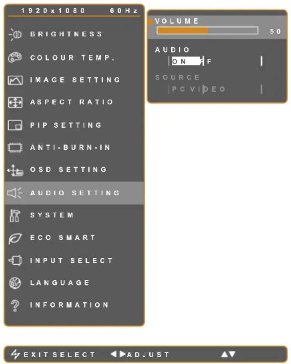
- Touch to call out the OSD window.
- Select AUDIO SETTING menu, then touch the ▶ button.
- Touch the ▲ or ▼ button to select an option.
| Item Function Operation Range | |||
| VOLUME | Adjusts the volume level of the built-in speaker.Note: If volume is adjusted but AUDIO is set to OFF, no sound comes out from the speaker. | Touch the ◀ or ► button to adjust the value. | 0 to 100 |
| AUDIO Turns the audio speaker ON or OFF. | Touch the ◀ or ► button to select the setting. | ONOFF | |
| SOURCE | Selects the audio source for the PC or Video input signal.Note: This menu option is only available if the input source is HDMI or DP. | PCVIDEO | |
ADJUSTING THE LCD DISPLAY
5.9 SYSTEM

- Touch to call out the OSD window.
- Select SYSTEM menu, then touch the button.
- Touch the ▲ or ▼ button to select an option.
| Item Function Operation Range | |||
| POWERSAVING | Enables or disables power saving mode.When the LCD display turns into power saving mode, the screen turns black and the LED indicator lights AMBER.Note:The amount of time for the display to enter power saving varies depending on the SOURCE DETECT setting. If the SOURCE DETECT is set to AUTO, the display checks all input source signals before entering power saving mode if no signal is detected; this takes up more time. If the SOURCE DETECT is set to MANUAL, the display enters power saving mode right away. | Touch the◄or►button to select the setting. | ONOFF |
| SOURCE DETECT | Sets the display to automatically or manually detect the input source signal. | AUTOMANUAL | |
ADJUSTING THE LCD DISPLAY
| Item Function Operation Range | |||
| MODE | Sets the current mode for better image display. | Touch the ◀ or ► button to select the setting. | TEXT GRAPHIC |
| Note: This menu option is only available if the input source is VGA with the resolution is either of the following: 640 x 350, 640 x 400, 720 x 350, or 720 x 400.For optimal performance, select:TEXT - This mode is suitable for viewing text documents when the resolution is 720 x 400 or 720 x 350.GRAPHIC - Graphics mode is suitable for viewing images when the resolution is 640 x 350 or 640 x 400. | |||
| DDC/CI | Activates the DDC/CI protocol to allow users to configure the monitor by a software using two wires on the VGA or DVI cables. | Touch the ◀ or ► button to select the setting. | ON OFF |
| DCR (Dynamic Contrast Ratio) | Activates DCR. This feature provides automatic adjustment of picture brightness and contrast at high speed and dynamic contrast range, such as when watching movies. DCR is suitable for indoor viewing. | ||
| BLUE SCREEN | Enables or disables the blue screen feature.If the setting is set to ON, it displays a blue screen when no signal is available. | ||
| SIGNAL INFO | Enables or disables the signal information to be displayed on the screen. | ||
| HDMI CEC | Enables or disables the HDMI CEC feature.If the setting is set to ON, you can control the connected HDMI CEC-compatible device on the same power on or power off status.Note: This menu option is only available if the input source is HDMI. | ||
| LOGO | Enables or disables the logo feature.If the setting is set to ON, the AG Neovo logo is briefly displayed after the display is powered on. | ||
| RECALL | Use to recall all to default settings, except Language, PIP, and the input source. | Touch the ► button to execute the function. | - |
ADJUSTING THE LCD DISPLAY
5.10 ECO SMART
With the built-in EcoSmart sensor, users can enable the Eco Smart feature to automatically adjust the LCD screen brightness according to the ambient light. This feature comforts the eyes and helps optimise energy efficiency.
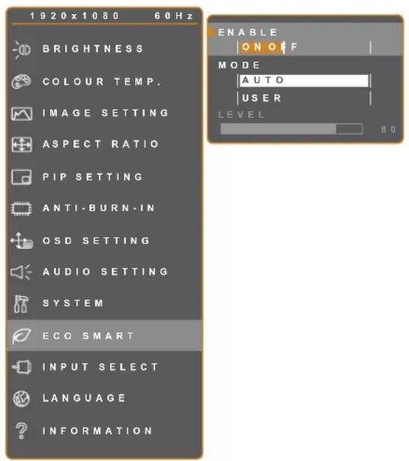
EXIT SELECT ADJUST
- Touch to call out the OSD window.
- Select ECO SMART menu, then touch the ▶ button.
- Touch the ▲ or ▼ button to select an option.
| Item Function Operation Value | |||
| ENABLE | Enables or disables the Eco Smart feature. | Touch the ◀ or ▶ button to select the setting. | ON OFF |
| MODE | Sets the auto brightness mode. | Touch the ◀ or ▶ button to select the setting. | AUTO USER |
| The mode can be set to:• AUTO - This mode is the default mode. The LCD brightness automatically adjusts to the ambient brightness.• USER - Allows you to manually adjust the LCD brightness. | |||
| LEVEL | Allows you to set the level of LCD brightness.Note: This menu option is only available if the MODE setting is to USER. | Touch the ◀ or ▶ button to adjust the value. | 0 to 100 |
ADJUSTING THE LCD DISPLAY
5.11 INPUT SELECT
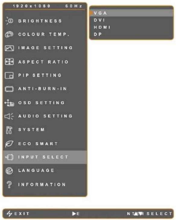
- Touch to call out the OSD window.
- Select INPUT SELECT menu, then touch the ▶ button.
- Touch the ▲ or ▼ button to select an option.
| Item Function Operation Value | |||
| VGA Sets VGA as the input source signal. | Touch the ▶ button to switch to the selected input source. | - | |
| DVI Sets DVI as the input source signal. | |||
| HDMI | Sets HDMI as the input source signal. | ||
| DP | Sets DP (DisplayPort) as the input source signal. | ||
CHAPTER 6: APPENDIX
6.1 Warning Messages
| Warning Messages Cause Solution | ||
| [CDCS] INPUT SIGNAL OUT OF RANGE | The resolution or the refresh rate of the graphics card of the computer is set too high. | · Change the resolution or the refresh rate of the graphics card. |
| [4TS8] NO SIGNAL | The LCD display cannot detect the input source signal. | · Check if the input source is turned ON.· Check if the signal cable is properly connected.· Check if any pin inside the cable connector is twisted or broken. |
| [22XT] OSD LOCK OUT | The OSD has been locked by the user. | · Unlock the OSD. Refer to page 18. |
 ANTI-BURN-IN ON ANTI-BURN-IN ON | The Anti-Burn-In function has been enabled by the user. | · Disable the Anti-Burn-In function. Refer to page 35. |
6.2 Troubleshooting
| Problem Possible Cause and Solution | |
| No picture.·LED indicator is OFF. | ·Check if the LCD display is turned ON.·Check if the power cord is properly connected to the LCD display.·Check if the power cord is plugged into the power outlet. |
| ·LED indicator is AMBER. | ·Check if the computer is turned ON.·Check if the computer is in standby mode, move the mouse or press any key to wake up the computer. |
| Image position is incorrect. | Adjust the H. POSITION and V. POSITION values. See IMAGE SETTING on page 29. |
| The displayed texts are blurry. | ·For VGA input, touch the ▼ button on the keypad to auto-adjust the display.·Adjust the IMAGE SETTING (see page 29). |
| The OSD menu can't be called out. | ·The OSD is locked. To unlock the OSD, see page 18. |
| Red, blue, green, white dots appear on screen. | ·There are millions of micro transistors inside the LCD display. It is normal for a few transistors to be damaged and to produce spots. This is acceptable and is not considered a failure. |
| No audio output. ·Check if the volume is set to 0 (see page 18 or 37).·Check if the AUDIO SETTING >AUDIO setting is set to OFF (see page 37).·For VGA or DVI input, check the audio setting of the computer.·For HDMI or DP input, select the correct audio input source (see page 37). | |
| PIP mode does not work. ·The main and sub input source signals are not compatible to be displayed together in PIP mode. Check the PIP Compatibility Table for details (see page 34). | |
| Cannot adjust the backlight setting. | ·The Eco Smart feature is enabled. Set the ECO SMART > ENABLE setting to OFF to disable the Eco Smart feature (see page 40). |
| The displayed picture looks distorted. | ·Adjust the aspect ratio (see page 32). |
| Dew formed on or inside the LCD display. | ·This normally happens when the LCD display is moved a cold room to a hot room temperature. Do not turn ON the LCD display, wait for the dew condensation to disappear. |
APPENDIX
| Problem Possible Cause and Solution | |
| Mist formed inside the glass surface. | This happens due to humid weather conditions. This is a normal occurrence. The mist will disappear after a few days or as soon as the weather stabilizes. |
| Faint shadows from a static image appear on the screen. | Turn off the LCD display for extended periods of time.Use a screen saver or a black and white image and run it for extended periods of time. |
APPENDIX
6.3 Transporting the LCD Display
To transport the LCD display for repair or shipment, place the display in its original packaging carton.
1 Put all the accessories in the box (if necessary). Place the two foam cushions on each side of the LCD display for protection.
2 Place the LCD display down in the box.
3 Place the accessories box on the designated area (if necessary).
4 Close and tape the box.

natural_image
Technical line drawing of a mechanical assembly with exploded view and component details (no text or symbols)CHAPTER 7: SPECIFICATIONS
7.1 Display Specifications
| X-22EX-24E | |||
| Panel Panel Size 2 | 1.5" 23.6" | ||
| Max. Resolution 1920 x | 1080 | ||
| Pixel Pitch 0.24825 mm | 0.2715 mm | ||
| Brightness 250 cd/m | 2 | 300 cd/ m2 | |
| Contrast Ratio 2,000,000 | 0:1 (DCR) | ||
| Viewing Angle (H/V) 170°/160° (Typical) | |||
| Display Colour 16.7M | |||
| Response Time 3 ms | |||
| Frequency (H/V) H: 24 kHz - 82 kHzV: 50 Hz - 75 Hz | |||
| Input | VGA | 15-Pin D-Sub | |
| DVI | 24-Pin DVI-D | ||
| HDMI | HDMI | ||
| DisplayPort | DisplayPort | ||
| Audio Audio In | Stereo audio | jack for PC (3.5mm) | |
| Speaker Out | 2W x 2 | ||
| Power In | Power Supply | External | |
| Power Requirements | DC 12V | ||
| Consumption | < 18W (On) | < 18W (On) | |
| < 0.3W (Stand-by) | < 0.3W (Stand-by) | ||
| < 0.3W (Off) | < 0.3W (Off) | ||
| Operating Conditions | Temperature | 0°C ~ 40°C (32°F ~ 104°F) | |
| Humidity | 10% ~ 90% | ||
| Storage Conditions | Temperature | -20°C ~ 60°C (-4°F ~ 140°F) | |
| Humidity | 5% ~ 95% | ||
| Weight | Without Base | 6.3 kg (13.9 lbs) | 7.2 kg (15.9 lbs) |
| With Base | 6.9 kg (15.2 lbs) | 7.8 kg (17.2 lbs) | |
Note: All specifications are subject to change without prior notice
7.2 Display Dimensions
7.2.1 X-22E Dimensions

7.2.2 X-24E Dimensions

Company Address: 5F-1, No. 3-1, Park Street, Nangang District, Taipei, 11503, Taiwan.

- Chapter 1: Product Description
- Chapter 2: Making Connections
- Chapter 3: Using the LCD Display
- Chapter 4: On Screen Display Menu
- TABLE OF CONTENTS
- Chapter 5: Adjusting the LCD Display
- Chapter 6: Appendix
- Chapter 7: Specifications
- SAFETY INFORMATION
- FCC Declaimers
- Dear users,
- Warning:
- WEEE
- PRECAUTIONS
- Notice
- Notice for the LCD Display
- Package Contents
- Note:
- PRODUCT DESCRIPTION
- Wall Mounting Installation Preparation
- Wall Mounting
- Remove the base stand.
- Wall mount the LCD display.
- Removing the Base Stand
- LCD Display Overview
- Front View and Keypad Buttons
- Display screen
- AUTO
- LEFT
- RIGHT
- UP
- DOWN
- MENU
- SOURCE
- POWER / LED indicator
- Rear View
- Connecting the Power
- Caution:
- MAKING CONNECTIONS
- Connecting Input Source Signals
- Connecting a Computer
- Using VGA Cables
- Using DVI Cables
- Using DisplayPort Cables
- Connecting an Audio Device
- Connecting a Video Device
- Using HDMI Cables
- Turning on the Power
- Selecting the Input Source Signal
- Notes:
- Adjusting the Volume
- Locking the OSD Menu
- Using Picture-in-Picture (PIP)
- PIP Options
- USING THE LCD DISPLAY
- PIP Swap
- Using Auto Adjustment Function
- Using the OSD Menu
- ON SCREEN DISPLAY MENU
- OSD Menu Tree
- BRIGHTNESS
- ADJUSTING THE LCD DISPLAY
- COLOUR TEMP.
- IMAGE SETTING
- ASPECT RATIO
- PIP SETTING
- ANTI-BURN-IN
- OSD SETTING
- AUDIO SETTING
- SYSTEM
- ECO SMART
- INPUT SELECT
- Warning Messages
- Troubleshooting
- APPENDIX
- Transporting the LCD Display
- Display Specifications
- Display Dimensions
- X-22E Dimensions
- X-24E Dimensions
Brand : AG Neovo
Model : X-24EW
Category : Screen