010-12831-00 - Hob Fusion - Free user manual and instructions
Find the device manual for free 010-12831-00 Fusion in PDF.

User questions about 010-12831-00 Fusion
0 question about this device. Answer the ones you know or ask your own.
Ask a new question about this device
Download the instructions for your Hob in PDF format for free! Find your manual 010-12831-00 - Fusion and take your electronic device back in hand. On this page are published all the documents necessary for the use of your device. 010-12831-00 by Fusion.
USER MANUAL 010-12831-00 Fusion
Universal Fixed Bracket for 8.8 in. Waketower Can Speakers Installation Instructions....2
Garmin ^® , the Garmin logo, FUSION ^® , and the Fusion logo, are trademarks of Garmin Ltd. or its subsidiaries, registered in the USA and other countries. These trademarks may not be used without the express permission of Garmin.
Universal Fixed Bracket for 8.8 in. Waketower Can Speakers Installation Instructions
Important Safety Information
WARNING
Failure to follow these warnings and cautions could result in personal injury, damage to the vehicle or vessel, or poor product performance.
This device must be installed according to these instructions.
Disconnect the vehicle's or vessel's power supply before beginning to install this product.
CAUTION
Continuous exposure to sound pressure levels over 100 dBA may cause permanent hearing loss. The volume is typically too loud if you cannot hear people speaking around you. Limit the amount of time you listen at high volume. If you experience ringing in your ears or muffled speech, stop listening and have your hearing checked.
Always wear safety goggles, ear protection, and a dust mask when drilling, cutting, or sanding.
NOTICE
When drilling or cutting, always check what is on the opposite side of the surface.
It is strongly recommended that you have your audio system installed by a professional installer to ensure optimum performance.
You must read all installation instructions before beginning the installation. If you experience difficulty during the installation, go to www.fusionentertainment.com for product support.
What's In the Box
- Two universal waketower brackets
- Two silicon grommets
- Plastic inserts to adjust for the waketower pole diameter These inserts allow the brackets to attach securely to a waketower with a pipe diameter from 33.4 mm (1.31 in.) to 63.5 mm (2.5 in.). See the specifications for a complete list of compatible pipe diameters.
- Eight hex screws and washers for securing the brackets to the speakers and the waketower
Tools Needed
- Drill and 12 mm ( ^1/_2 in.) drill bit
- 6 mm hex driver or hex key
- Scissors or knife
- Wire strippers
- Solder and heat-shrink tubing for wire connections
NOTE: For customized installations, additional tools and materials may be needed.
Mounting the Bracket
You can mount FUSION® Waketower Can speakers (sold separately) to a waketower using the included brackets.
1 If necessary, mark the locations on the waketower where you plan to mount the speakers.
2 If necessary, drill a 12 mm ( ^1/_2 in.) cable pass-through holes in the bottom of the waketower pipe.
3 If necessary, route the speaker and LED power wires (not included) through the waketower to the mounting locations.
4 If necessary, starting with one mounting location, place the included silicon grommet onto the hole in the bottom of the waketower pipe.
The grommet protects the speaker cable from sharp edges on the waketower pipe.
5 Select the appropriate plastic spacer to mount the bracket to the waketower pipe.
6 Push each half of the spacer into the base and top of the bracket.
The spacer halves should fit securely into each half of the bracket.
7 Feed the speaker cable from the FUSION Waketower Can speaker through the base of the bracket and attach the bracket to the speakers using the included screws with a 6 mm hex driver or hex key.
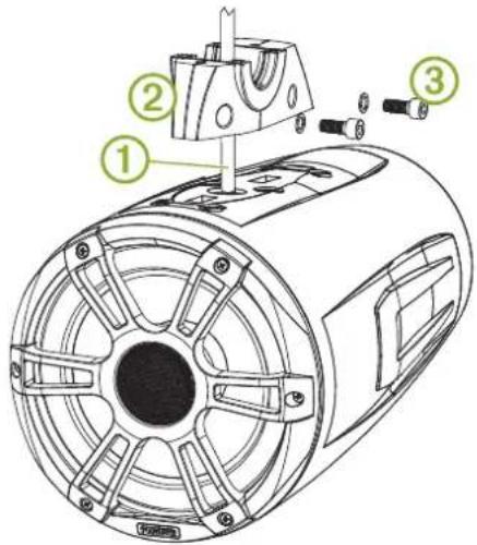
text_image
Technical diagram of an electric motor with labeled components and exploded view8 Using the installation instructions provided with the FUSION Waketower Can speakers, connect the speaker and LED wires.
9 Feed the connected wires through the pass-through hole and grommet into the waketower pipe.
10 Place the top of the bracket over the pipe, and hold it against the base of the bracket.
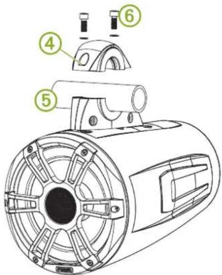
text_image
Technical diagram of a mechanical device with numbered parts labeled 4, 5, and 611 Attach the top of the bracket to the base of the bracket using the included screws with a 6 mm hex driver or hex key.
12 Repeat these steps for additional brackets.
Specifications
| Material Bracket: al | luminum alloyGrommet: siliconSpacer: plastic |
| Supportedwaketower pipe sizes | 33.4 mm (1.31 in.), 42.2 mm (1.66 in.), 48.3 mm (1.90 in.), 50.8 mm (2.00 in.), 57.2 mm (2.25 in.), 60.3 mm (2.37 in.), and 63.5 mm (2.50 in.) outer diameter using the included spacers |
Bracket Side Dimensions
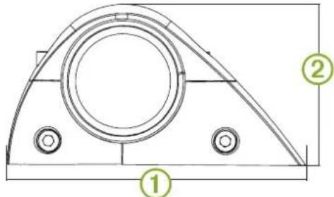
text_image
Technical drawing of a mechanical component with labeled parts 1, 2, and circular features| 1 | 174 mm ( 6^7/_8 in.) |
| 2 | 94 mm ( 3^3/_4 in.) |
Bracket Top Dimensions
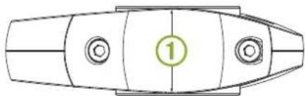
natural_image
Top-down schematic of a boat hull with marked parts and a numbered marker (1), no text or symbols present.| 1 | 52 mm ( 2^1/_16 in.) |