PLMRC500X1 - Receiver Pyle - Free user manual and instructions
Find the device manual for free PLMRC500X1 Pyle in PDF.

| Product Type | Marine Bluetooth Receiver |
| Brand | Pyle |
| Model | PLMRC500X1 |
| Dimensions (W x H x D) | 7.1 x 2.5 x 5.1 inches (standard DIN) |
| Weight | 2.1 lbs |
| Power Supply | 12V DC (marine/vehicle electrical system) |
| RMS Power Output | 50 watts x 4 channels |
| Peak Power Output | 200 watts x 4 channels |
| Bluetooth Version | 5.0 with A2DP, AVRCP |
| Supported Audio Formats | MP3, WMA, WAV, FLAC |
| Radio Tuner | AM/FM with 30 presets |
| USB Port | 1 x USB-A (charging and playback) |
| AUX Input | 1 x 3.5mm front auxiliary |
| Outputs | 4-channel RCA preamp outputs, 1 subwoofer output |
| Water Resistance Rating | IPX6 (weatherproof for marine use) |
| Display | LCD with variable color illumination |
| Remote Control | Wireless remote included |
| Mounting | Standard DIN single-DIN chassis |
| Additional Features | Hands-free calling, advanced sound controls, Silicone-sealed face |
Frequently Asked Questions - PLMRC500X1 Pyle
User questions about PLMRC500X1 Pyle
0 question about this device. Answer the ones you know or ask your own.
Ask a new question about this device
Download the instructions for your Receiver in PDF format for free! Find your manual PLMRC500X1 - Pyle and take your electronic device back in hand. On this page are published all the documents necessary for the use of your device. PLMRC500X1 by Pyle.
USER MANUAL PLMRC500X1 Pyle
text_image
Collection of symbolic and stylized icons including stars, asterisks, and symbols in a rowClass D Compact Designed Suit for Car, ATV, UTV, 4X4, Jeep, Motorcycle and Marine, and any other Weather Resistant Application
USER GUIDE
INTRODUCTION
This power amplifier has been designed to provide high quality performance with a minimum of maintenance. However, it's performance will only be as good as the care and quality of components with which is installed.
We therefore advise that you read these instructions very carefully to familiarize yourself with the product and it's features.
Before installing the power amplifier please read this instruction manual carefully. The instructions for mounting and connecting the set have to be followed precisely. If necessary, a service center should be consulted.
All connections for DC power, signal input and speaker outputs can be carried out easily and safely byway of RCA and screwed terminals.
INSTALLATION INSTRUCTIONS
Please choose a mounting place without any direct weather influences.
Note that the amplifier generates heat so that a well ventilated place is necessary. According to your car's construction the set can be made very carefully in order to ensure the amplifier's full performance and reliability.
Keep the wire connections as short as possible with sufficient dimensions in order to minimize power losses and provide a higher audio output of the system.
For safety reasons route all power and speaker wiring by using the exiting wire channels. To minimize damage to the cables, take care that they do not pass sharp edged metal. Lay all cables as far away as possible from the ignition cables, modules in the boot and under the key dashboard, as this create interference.
Add a fuse into the (+) power cable in a distance of not more than 30 cm from the positive battery pole.
Keep the length of the power wires as short as possible. It is better to use power cables which are short and then longer speaker cables.
In order to reduce interference, also pay attention to the instructions.
PRECAUTIONS
• This unit is designed for negative ground 12-14.50 Volts (DC) operation only
- Use speakers with an impedance of 1 to 4 Ohms (2 to 8 Ohm when used as bridged two amplifier)
- Avoid installing the unit where:
- It would be subject to high temperatures, such as from direct sunlight or hot air from the heater.
-
It would be exposed to rain or moisture.
• It would be subject to dust or dirt. -
If your car is parked in direct sunlight and there is a considerable rise in temperature inside the car, allow the unit to cool off before operation.
- When installing the unit horizontally, be sure not to cover the heatsink fins with the floor carpet.
- If this unit is placed too close to the car radio, an interference may occur in this case, separate the amplifier from the car radio.
- This power amplifier employs a protection circuit to protect the transistors and speakers if the amplifier malfunctions.
- Do not attempt to test the protection circuits by covering the heatsink or connecting improper loads.
- Do not use the unit with a weak auto battery as its optimum performance depends on a normal battery supply voltage.
- For safety reasons, keep the volume of your car audio system moderate so that you can still hear normal traffic sounds outside your car.
FUSE REPLACEMENT
If the fuse blows, check the power connection and replace the fuse. If the fuse blows again after replacement, there may be an internal malfunction. In this case, consult your dealer.
WARNING: Use the specified amperage fuse. Use of a higher amperage fuse may cause serious damage.
PROTECTION CIRCUIT
This amplifier is provided with a protection circuit which operates in the following cases when:
• the unit is overheated.
• the speaker terminals are short circuited.
WIRING INSTRUCTIONS
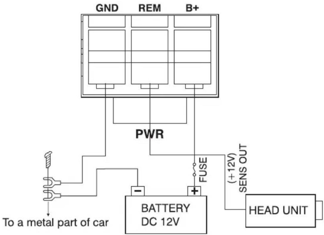
POWER CONNECTION
The battery terminal (BATT) must be connected directly to the positive terminal of the vehicle battery to provide an adequate voltage source and minimize noise. Connecting the battery terminal lead to any other point (such as the fuse block) will reduce the power output and may cause noise and distortion.
Use only #10 gauge or thicker (smaller gauge #) wire for this lead and connect it to the terminal of the battery after all other wiring is completed.
GROUND CONNECTION
The ground terminal (GND) connection is also critical to the correct operation of the amplifier. Use a wire of the same gauge as the power connection (#10 or thicker) and connect it between the ground terminal (GND) of the amplifier and a metal part of the vehicle close to the mounting location. This wire should be as short as possible and any paint or rust at the grounding point should be scraped away to provide a clean metal surface to which the end of the ground wire can be screwed or bolted.
REMOTE TURN-ON CONNECTION
The amplifier is turned on by applying + 12V to the remote turn-on terminal (REM). The wire lead to this terminal should be connected to the "Auto-Antenna" lead from the car stereo which will provide the + 12V only when the car stereo is turned on. If the car stereo does not provide an "Auto-Antenna" lead, the remote turn-on lead may be wired to an "Accessory" or "Radio" terminal in the car's fuse block. This will turn the amplifier on and off with the ignition key, regardless of whether the car stereo is on or off. The remote turn-on lead does not carry large currents. So # 20 gauge wire may be used for this application.
SPEAKER CONNECTIONS
Depending on the type and number of speakers used with the amplifier wire them to the speaker terminals as per the appropriate wiring diagram. For most applications # 18 gauge wire should be used for the speaker leads but in no case thinner than # 18 gauge. For leads is excess of 10 feet # 12 gauge is recommended. When wiring the speakers, pay careful attention to the polarity of the terminals on the speakers and make certain they correspond to the polarity of the corresponding terminals on the amplifier. Do not ground any speaker leads to the chassis of the vehicle.
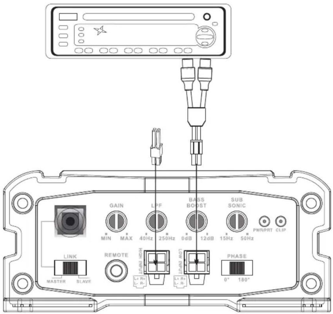
INPUT WIRING DIAGRAM
text_image
GAIN LPF BASS BOOST SUB SONIC MIN MAX 40Hz 250Hz 0dB 12dB 15Hz 50Hz PWR/PRT CLIP LINK REMOTE LHIN LHIN MCT LHIN MCT PHASE MASTER SLAVE 0° 180°SPEAKER CONNECTIONS
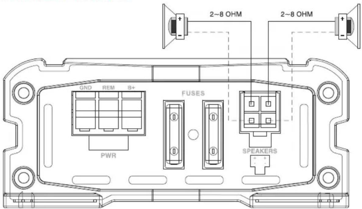
text_image
GND REM B+ PWR FUSES 2~8 OHM 2~8 OHM SPEAKERSPOWER CONNECTION LEADS
flowchart
graph TD
    A["GND"] --> B["PWR"]
    C["REM"] --> B
    D["B+"] --> B
    E["To a metal part of car"] --> F["-"]
    F --> G["BATTERY DC 12V"]
    G --> H["HEAD UNIT"]
    I["FUSE"] --> G
    J["(+12V) SENS OUT"] --> H
    style A fill:#f9f,stroke:#333
    style C fill:#f9f,stroke:#333
    style D fill:#f9f,stroke:#333
    style E fill:#ccf,stroke:#333
    style F fill:#ccf,stroke:#333
    style G fill:#ccf,stroke:#333
    style H fill:#ccf,stroke:#333
NOTES ON THE POWER SUPPLY
- Connect the + 12V power input lead only after all other leads have been connected.
- Be sure to connect the ground wire of the unit securely to a metal part of the car.
- A lose connection may cause amalfunction of the amplifier.
- REM: The unit is turned on by applying + 12 Volts to this terminal. This terminal does not draw heavy current like the tow Power Terminals so a thinner connecting wire is acceptable. Standard 20 GAUGE is fine and the standard color is blue. If the radio is equipped with a Power Antenna control wire, it can drive this terminal. If the Power Antenna wire is already in use, you can still splice into it. With this method, the unit will turn on automatically with the radio.
- Use the power supply lead with a fuse attached whose value is the same as original fuse.
- Place the fuse in the power supply lead as close as possible to the car battery.
- During a full power operation, maximum current will run through the system. Therefore, make sure that the leads to be connected to the +12V and GND terminals of the unit respectively must be larger than 10 - Gauge (AWG. 10).
OPERATION
After the amplifier has been installed and all connections have been made carefully and securely, turn the radio ON so that the amplifier is switched on automatically. After a short power-on period, the amplifier reaches its full performance. Now turn up the volume slowly using the volume control of the radio. If there is no sound or only a distorted replay, switch off the radio immediately - the amplifier will also switch off automatically - and check if all connections have been made correctly.
GAIN = INPUT LEVEL CONTROL
The input level control allows the system to work well within a wide range of output level. Choose the adjustment in the way that you achieve a sound most possibly without any distortion.
As a guideline the following procedure is recommended:
- If you use several amplifiers, the adjustment has to be made for each set separately. Tune in the volume of your car radio to 2/3 of the maximum volume. Now turn the gain control of the amplifier from "Min" to "Max" direction until you can hear distortions. Then turn the level control a little back to "Min". The gain control adjustment is finished now.
PHASE SHIFT
Allows you to change the phase of your subwoofer from 0 to 180 degrees to help compensate for timing differences between drivers.
LOW PASS FILTER
The lower frequency under setting point can be pass.
SUBSONIC FILTER
The higher frequency above setting point can be pass.
BASS BOOST CONTROLS
This amplifier has Bass controls for making good sound combination.
FUSE
The amplifier is equipped with a plug-in auto fuse protecting the set against fault conditions. Do not use a fuse with a higher value and never bridge the fuse over, as this may lead to irreparability damage so that any claim for warranty is denied.
GND (-) = GROUND CONNECTION
Connect the GND terminal to the chassis ground of your car and take care of best electric and mechanic contact.
In doing so, drill a hole in to the car chassis near the amplifier then remove color, dirt, or any other substance from the ground point.
Thereafter fasten the cable end with added ring terminal by using a screw. Ensure that the ground connection is as short as possible and that the cable diameter is sufficient (min 4mm").
Route the ground cables from the radio and all other equipment parts, like equalizer, active crossover network or other amplifiers, to the same ground point.
+ 12V = POWER SUPPLY
Connect the BATT terminal to the positive pole of the battery with a lead cable and add a fuse into the power cable in a distance of not more than 30 cm from the battery. The lead cable's diameter should be at least 4 mm' for a length of 3 m and 6mm" for a length of 6m.
REM (ON/OFF) REMOTE CONTROL
Connect the REM terminal to the automatic antenna connector of your car radio. Now when turning ON and OFF your car radio, the amplifier automatically switches ON and OFF. A cable diameter of 0.5 mm' is sufficient.
TROUBLESHOOTING
No Function
The connection cable is not connected correctly (=terminal + I2V/GND/REM).
Ensure that all connections and mechanic contact and that the jacket has been removed. The fuse is defective-pay attention to the correct value of a new fuse!
No Sound
Speaker cable or speaker plug are not connected correctly.
No Sound/Red LED Protection is lit
The plus and minus wires of the speaker cable have contact, thus eliminate the short circuit. If you use a 1 Ohm speaker and the set is overloaded, then turn the gain control to "min" until the operation is free of trouble.
Poor Sound Quality (Distortions)
The speakers are overloaded, therefore turn down the volume level and check the volume control positions.
No Stereo Sound and Weak Bass
Speaker cables (+) and (-) are mixed up, unit wired out of phase.
California Prop 65 Warning
! WARNING:
This product contains Di (2-ethylhexyl) phthalate (DEHP) which is known to the state of California to cause cancer birth defects and other reproductive harm. Do not ingest.
For more info go to: www.P65warnings.ca.gov
INTERFERENCE
All cables can source and create interference. The power cable and Cinch/RCA audio cable are very prone to interference; the remote cables are less prone. There is often interference caused by the generator (piping), ignition (cracking) or other car electronic parts. Most of these problems can be eliminated by correct and careful cabling. In doing so, here are the following guidelines:
- Use only a screened audio cable for the wiring between "low level in" of the amplifier and RCA or DIN output of the radio.
- Lay the signal, speaker and power cables separately with enough distance from one another and also from each others car cable. If not possible, you can lay the circuit and ground cable together with the serial cables. Audio and speaker cable should be as far away from these as possible.
The REM cable to the automatic antenna output of the radio can be laid together with the signal cables.
- Avoid ground loops by laying the ground wiring of all components to a center point in a star-like way. You can find the best central point in measuring the voltage directly at the battery. Now compare this voltage value with the chosen ground point and the (+) terminal of the amplifier. If measured voltage is only slightly different, you've found the correct central. Otherwise you have to look for another point. You should measure with the ignition point for earth being switched on and additionally switched on consumers (rear window heating and light).
- If there are pickups from external electrical sources into the speaker cables, divide the core leads and twist them together.
- If there are noises from the car electrics, add an interference suppression choke into the power wiring.
- If there are humming noises, use thicker ground cables or add further ground cables to the chassis.
- To reduce contact resistance and bad loose contact, please solder the cable ends or use multi core cable ends, spade terminals or others. Gold Plated spade terminal are free of corrosion and have the lowest contact resistance.
- Should all these measures be without any success, the use of a ground loop isolator may solve the problem.
Features:
• Mono Block Audio Amp System
• Weather Resistant Class D Compact Amplifier
- IPX4 Effect
- Integrated Power Wiring Harness
- Perfect for Custom Installations & Applications
- Ability to Connect & Stream Audio from External Devices
- Speaker Wiring Connectivity
- Soft Turn On/Off
• Overload & Power Protection Circuitry
What's in the Box:
• Mono-Block Audio Amp System
- Bag of Mounting Hardware
- Remote Control with Cable
- Speaker Output Wire
- Low-Level Input Wire
• Hi-Level Input Wire
- Remote In Wire (Blue)
• Power Connector
Technical Specs:
• RMS Power Output:
• 190W x 1 @ 4 ohm @ 1% THD @ 14.4V
• 310W x 1 @ 2 ohm @ 1% THD @ 14.4V
- 500W x 1 @ 1 ohm @ 1% THD @ 14.4V
• MAX Power Output:
- 400W @ 4 ohm
- 650W @ 2 ohm
- 1000W @ 1 ohm
• THD: 0.1%
- S / N Ratio: >90 dB
• Frequency Response: 10Hz-250Hz
- Fuse: 25 ~A × 2
- Power: DC 12V
- Amp Dimensions (L x W x H): 7.95" x 4.33" x 1.87"-inches
PYLE
PyleUSA.com

natural_image
Illustration of a laptop with a red checkmark on screen, next to partial text 'V H N W' (no readable document content)VISIT US ONLINE:
Have a question?
Need service or repair?
Want to leave a comment?
PyleUSA.com/ContactUs

Questions? Issues?
We are here to help!
Phone: (1) 718-535-1800
Email: support@pyleusa.com