RCI WPDT - Access Control System Dormakaba - Free user manual and instructions
Find the device manual for free RCI WPDT Dormakaba in PDF.


| Product Type | Wireless Panic Device with Door Position Monitor |
| Dimensions | Approx. 150 x 80 x 40 mm (trim plate) |
| Weight | Approx. 300 g (trim only) |
| Power Supply | 6VDC (4x AA alkaline batteries, included) |
| Wireless Protocol | Proprietary 900 MHz / 2.4 GHz (region dependent) |
| Battery Life | Up to 2 years under normal use |
| Main Functions | Panic egress release, door position monitoring, remote lockdown capability |
| Environmental Rating | Indoor use only; temperature -10°C to 50°C |
| Compliance | ANSI/BHMA Grade 1, UL listed, FCC/IC certified |
| Installation | Surface mount on door frame; no wiring required |
| Maintenance | Clean with damp cloth; avoid solvents; replace batteries annually |
| Safety Features | Tamper alarm, low battery warning, fail-secure or fail-safe mode configurable |
| Spare Parts / Repairability | Battery holder, latch assembly, cover plate available; field replaceable |
| General Information | Part of the Dormakaba RCI series; intended for egress doors in commercial facilities |
Frequently Asked Questions - RCI WPDT Dormakaba
User questions about RCI WPDT Dormakaba
0 question about this device. Answer the ones you know or ask your own.
Ask a new question about this device
Download the instructions for your Access Control System in PDF format for free! Find your manual RCI WPDT - Dormakaba and take your electronic device back in hand. On this page are published all the documents necessary for the use of your device. RCI WPDT by Dormakaba.
USER MANUAL RCI WPDT Dormakaba
WIRELESS POWER & DATA TRANSFER
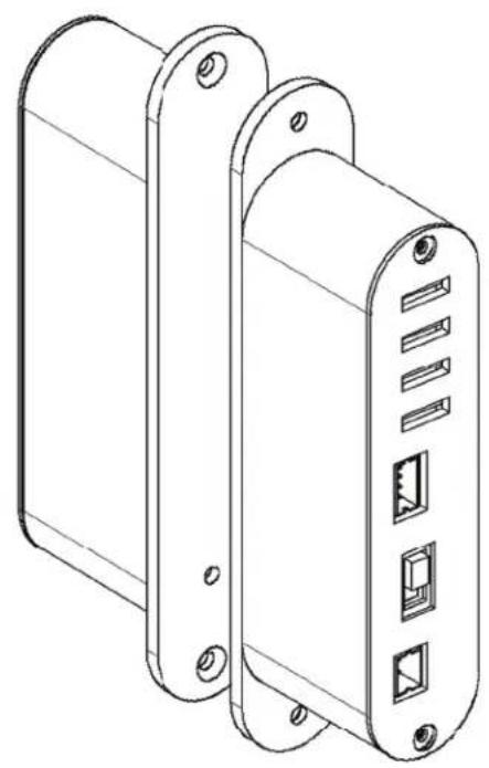

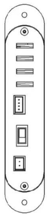
Specifications:
• Input Voltage = 24VDC
• Input Power = 600 mA minimum
• Maximum Sensor Gap = 7.0 mm 1/4"
• Fail Secure Locks only*
• Output Voltage 12VDC @ 600mA or 24VDC @ 300mA selectable*
• Door Position Sensor*, 60V AC/DC@200 mA
• 2 Input/Outputs for Monitoring (REX, LBM)*, 30VDC@1A & 125VAC@300mA
• 3 Second Fixed Unlock Time or 0-90 Second (by switch activation)
- Operating Temperature -20 \~ 60°C (-4 \~ 140°F)
- Error Indicator LED (frame side)**
* Response time can be affected by installation and door gap
** Indicates excessive load or improper input voltage
Package Content
1) Frame side unit
2) Door side unit
3) 4 mounting tabs
4) 6 washers
5) 4 M3 wood screws
6) 12 M3 steel mounting screws
7) templates for both wood and hollow metal
8) wire harnesses
FCC Warning Statement
This device complies with Part 15 of the FCC Rules. Operation is subject to the following two conditions:
(1) This device may not cause harmful interference and
(2) This device must accept any interference received, including interference that may cause undesired operation.
NOTE: THE GRANTEE IS NOT RESPONSIBLE FOR ANY CHANGES OR MODIFICATIONS NOT EXPRESSLY APPROVED BY THE PARTY RESPONSIBLE FOR COMPLIANCE. SUCH MODIFICATIONS COULD VOID THE USER'S AUTHORITY TO OPERATE THE EQUIPMENT.
IC Warning Statement
Canada, Industry Canada (IC) Notices
This Class B digital apparatus complies with Canadian ICES-003 and RSS-247. Operation is subject to the following two conditions: (1) this device may not cause interference, and (2) this device must accept any interference, including interference that may cause undesired operation of the device.
Radio Frequency (FR) Exposure Information
The radiated output power of the Wireless Device is below the Industry Canada (IC) radio frequency exposure limits. The Wireless Device should be used in such a manner such that the potential for human contact during normal operation is minimized.
This device has also been evaluated and shown compliant with the IC RF Exposure limits under mobile exposure conditions (antennas are greater than 20cm from a preson's body).
RED AND BLACK = 24 VDC INPUT @ 600 mA minimum
GREEN AND YELLOW MOMENTARY CLOSURE = 3 SECOND UNLOCK TIME BROWN AND YELLOW CLOSURE = 0 - 90 SECOND UNLOCK TIME
BLUE AND GRAY = DOOR POSITION OUTPUT YELLOW AND WHITE = ERROR STATUS INDICATION
SWITCH #1 = SPDT OUTPUT FROM DOOR SIDE SIGNAL
SWITCH #2 = SPDT OUTPUT FROM DOOR SIDE SIGNAL
* ERROR OUTPUT WHEN EXCESSIVE LOAD APPLIED OR IMPROPER INPUT VOLTAGE
![graph TD A["DOOR SIDE FRAME SIDE"] --> B["POWER SUPPLY 24VDC 600 mA minimum"] B --> C["RED + BLACK -"] C --> D["GRN"] C --> E["YEL"] C --> F["BRO"] D --> G["BLU"] D --> H["GRAY"] D --> I["YEL"] D --> J["WHT"] E --> K["} DOOR POSITION OUTPUT"] E --> L["} ERROR OUTPUT"] G --> M["WHT= N/C 1"] G --> N["…](/content/2026/05/1057257/images/1f1bda857d904056461bf2fb23064d1d239f551af959648f1a54c8a3bab3453e.jpg)
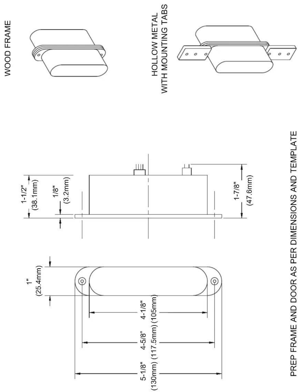
PREP FRAME AND DOOR AS PER DIMENSIONS AND TEMPLATE SUPPLIED.
WPDT - LED Status Indications
Transmitter (TX)
| Green LED Red LED Comments | |||
| Standby | On | Flashing 0.4 seconds | Door closed and locked |
| Unlock Off | On solid Door is unlocked | ||
| Error Off | flashing 0.2 seconds Incorrect voltage/current | ||
| Error Off | flashing 0.5 seconds Unit over temperature | ||
Receiver (RX)
| Red LED Comments | |||
| Standby | Flashing 0.4 seconds | Door closed and locked | |
| Unlock On Solid Door is unlocked | |||
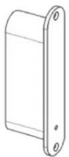

status LED

Brand : Dormakaba
Model : RCI WPDT
Category : Access Control System