
TGR100SMT - Air conditioner GORENJE - Free user manual and instructions
Find the device manual for free TGR100SMT GORENJE in PDF.


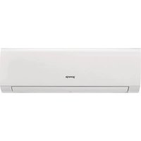
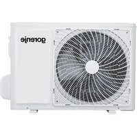
| Product Type | Split Air Conditioner (Wall-mounted) |
| Brand | Gorenje |
| Model | TGR100SMT |
| Cooling Capacity (BTU/h) | 12,000 |
| Heating Capacity (BTU/h) | 12,000 (Heat Pump) |
| Energy Efficiency Ratio (EER) | 3.5 |
| Power Supply | 220-240 V ~ 50 Hz |
| Indoor Unit Dimensions (WxHxD) | 800 x 300 x 200 mm |
| Outdoor Unit Dimensions (WxHxD) | 700 x 500 x 250 mm |
| Indoor Unit Weight | 10 kg |
| Outdoor Unit Weight | 25 kg |
| Refrigerant Type | R32 |
| Airflow Speed Levels | 3 (Low, Medium, High) |
| Noise Level (Indoor) | 25-40 dB(A) |
| Noise Level (Outdoor) | 50-55 dB(A) |
| Functions | Cooling, Heating, Dehumidification, Fan, Auto, Sleep, Timer, Turbo, Swing |
| Filter Type | Washable Mesh Filter |
| Maintenance | Clean filter every 2 weeks; professional service annually |
| Safety Features | Overload protection, Auto restart, Anti-freeze, Child lock (remote) |
| Spare Parts Availability | Filters, remotes, control boards, fan motors |
| Repairability Index | 7.5 / 10 |
Frequently Asked Questions - TGR100SMT GORENJE
User questions about TGR100SMT GORENJE
0 question about this device. Answer the ones you know or ask your own.
Ask a new question about this device
Download the instructions for your Air conditioner in PDF format for free! Find your manual TGR100SMT - GORENJE and take your electronic device back in hand. On this page are published all the documents necessary for the use of your device. TGR100SMT by GORENJE.
USER MANUAL TGR100SMT GORENJE
TGR 30-120 SM
EN
Instructions for Use 3
HR BIH
Upute za upotrebu 11
MK
The appliance may be used by children older than 8 years old, elderly persons and persons with physical, sensory or mental disabilities or lacking experience and knowledge, if they are under supervision or taught about safe use of the appliance and if they are aware of the potential dangers.
Children should not play with the appliance.
Children should not clean or perform maintenance on the appliance without supervision.
⚠️ Installation should be carried out in accordance with the valid regulations and according to the instructions of the manufacturer and by qualified staff.
In a closed, pressurised system of installation, it is obligatory to install a safety valve on the inlet pipe with a rated pressure of 0.6 MPa (6 bar), 0.9 MPa (9 bar) or 1.0 MPa (10 bar) (see the label), which prevents the elevation of pressure in the boiler by more than 0.1 MPa (1 bar) above the rated pressure.
Water may drip from the outlet opening of the safety valve, so the outlet opening should be set to atmospheric pressure.
The outlet of the safety valve should be installed facing downwards and in a non-freezing area.
To ensure proper functioning of the safety valve, the user should perform regular controls to remove limescale and make sure the safety valve is not blocked.
Do not install a stop valve between the water heater and the safety valve, because it will impair the pressure protection of the heater!
⚠️ Before connecting it to the power supply, the water heater must be filled with water!
The heater is equipped with an additional thermal cut-off for protection in case of failure of the operating thermostat. In this case, however, the temperature of the water in the heater can reach up to 130 °C according to the safety standards. During the water supply installation, the possibility of temperature overloads should be taken into account.
If the heater is to be disconnected from the power supply, please drain any water from the heater to prevent freezing.
⚠️ Please do not try to fix any defects of the water heater on your own. Call the nearest authorised service provider.

Our products incorporate components that are both environmentally safe and harmless to health, so they can be disassembled as easily as possible and recycled once they reach their final life stage. Recycling of materials reduces the quantity of waste and the need for production of raw materials (e.g. metals) which requires a substantial
amount of energy and causes release of harmful substances. Recycling procedures reduce the consumption of natural resources, as the waste parts made of plastic and metal can be returned to various production processes.
For more information on waste disposal, please visit your waste collection centre or the store where the product was purchased.
Dear buyer, thank you for purchasing our product. Prior to the installation and first use of the electric water heater, please read these instructions carefully.
In accordance with the latest guidelines, we have developed for our more demanding customers the electric water heater TGR equipped with an intelligent electronic regulator allowing the setting of the temperature of water in the heater as well as smart "ECO S " mode of operation. The heater records your habits and after a while, it calculates the optimal operating mode that enables minimal use of electric energy necessary to meet your warm water needs.
This water heater has been manufactured in compliance with the relevant standards and tested by the relevant authorities as indicated by the Safety Certificate and the Electromagnetic Compatibility Certificate. The technical characteristics of the product are listed on the label affixed between the inlet and outlet pipes. The installation must be carried out by qualified staff. All repairs and maintenance work within the water heater, e.g. lime removal or inspection/replacement of the protective anticorrosion anode, must be carried out by an authorised maintenance service provider.
INSTALLATION
The water heater shall be installed as close as possible to the outlets. When installing the water heater in a room with a bathtub or shower, take into account the requirements defined in IEC Standard 60364-7-701 (VDE 0100, Part 701). It has to be fitted to the wall using appropriate wall screws with a minimum diameter of 8 mm. A wall with a poor load-bearing capacity must be properly reinforced where the heater will be installed. The water heater may only be fixed upon the wall vertically. We recommend the distance between the water heater and the ceiling is large enough to allow simple replacement of the Mg anode (see dimension G in the Installation Drawing), in order to avoid unnecessary dismounting of the heater during the servicing intervention.

| A B C G | ||||
| TGR 30 SM | 476 | 275 | 173 | 80 |
| TGR 50 SM | 578 | 365 | 185 | 130 |
| TGR 80 SM | 783 | 565 | 190 | 180 |
| TGR 100 SM | 943 | 715 | 200 | 260 |
| TGR 120 SM | 1098 | 865 | 205 | 260 |
Connection and installation dimensions of the water heater [mm]
CONNECTION TO THE WATER SUPPLY
The water heater connections for the inlet and outlet of water are colour-coded. The inlet of cold water is marked with blue colour, while the hot water outlet is marked with red colour.
The water heater can be connected to the water supply in two ways. The closed-circuit pressure system enables several points of use, while the open-circuit gravity system enables a single point of use only. The mixer taps must also be installed in accordance with the selected installation mode.
The open-circuit gravity system requires the installation of a non-return valve in order to prevent the water from draining out of the tank in the event of the water supply running dry or being shut down. This installation mode requires the use of a cross-flow mixer tap. As the heating of water expands its volume, this causes the tap to drip. The dripping cannot be stopped by tightening it further; on the contrary, the tightening can only damage the tap.
The closed-circuit pressure system requires the use of pressure mixer taps. For safety reasons the supply pipe must be fitted with a safety valve or alternatively, a valve of the safety class that prevents the pressure in the tank from exceeding the nominal pressure by more than 0.1 MPa (1 bar). The outlet opening on the relief valve must be equipped with an outlet for atmospheric pressure.
The heating of water in the heater causes the pressure in the tank to increase to the level set by the safety valve. As the water cannot return to the water supply system, this can result in dripping from the outlet of the safety valve. The drip can be piped to the drain by installing a catching unit just below the safety valve. The drain installed below the safety valve outlet must be piped down vertically and placed in an environment that is free from the onset of freezing conditions.
In case the existing plumbing does not enable you to pipe the dripping water from the safety valve into the drain, you can avoid the dripping by installing a 3-litre expansion tank on the inlet water pipe of the boiler.
In order to ensure correct operation of the safety valve, the user must carry out periodic inspections of the relief valve to remove any limescale and check that the safety valve is not blocked. To check the valve, open the outlet of the safety valve by turning the handle or unscrewing the nut of the valve (depending on the type of valve). The valve is operating properly if water comes out of the nozzle when the outlet is open.
![graph LR A["Top Tank"] --> B["Turb"] B --> C["Reactor Unit 1"] C --> D["Flow Control Unit 2"] D --> E["Return Line 3"] E --> F["Flow Control Unit 4"] F --> G["Return Line 5"] G --> H["Harm Flow H"] style A fill:#f9f,stroke:#333 style H fill:#ccf,stroke:#333](/content/2026/05/1055862/images/bf32f6d6ba1676d32df471983be0cad9c6f84e107d2aaf12a6bb62b82c0a2cbd.jpg)
Closed (pressure) system
![graph TD A["Top Tank"] --> B["T"] B --> C["H"] C --> D["Valve 3"] C --> E["Valve 5"] D --> F["Return Line"] E --> F style A fill:#f9f,stroke:#333 style B fill:#ccf,stroke:#333 style C fill:#cfc,stroke:#333 style D fill:#fcc,stroke:#333 style E fill:#fcc,stroke:#333](/content/2026/05/1055862/images/82c8c90c822ce9a56dfd63cd7c9b71efb014bc5bd3c11335058c5b9ad6f41277.jpg)
Open (non-pressure) system
Legend:
1 - Safety valve 2 - Test valve 3 - Non-return valve 4 - Pressure reduction valve 5 - Closing valve
6 - Checking fitting 7 - Funnel with outlet connection 8 - Expansion tank H - Cold water T - Hot water
No closing valve may be installed between the water heater and the safety valve, as it could impede the function of the safety valve.
The heater can be connected to the domestic water supply network without a pressure-reducing valve if the pressure in the network is lower than the nominal pressure. If the pressure in the network exceeds the nominal pressure, a pressure-reducing valve must be installed.
Before connecting it to the power supply, the water heater must be filled with water. When filling the heater for the first time, the hot water tap on the mixing tap must be opened. When the heater is filled with water, the water starts to run through the outlet pipe of the mixing tap.
CONNECTING THE WATER HEATER TO THE POWER SUPPLY NETWORK
Before connecting to the power supply network, install a power supply cord in the water heater, with a minimum diameter of 1.5 mm2 (H05VV-F 3G 1.5 mm2 ). To do this, the protective plate must be removed from the water heater.

Connecting the heater to the power supply network must be carried out in accordance with the standards for electric appliances. To comply with national installation regulations, an all-pole disconnect switch must be installed between the water heater and the power supply network. When the heater is connected to the power supply, both lights on the front panel will light up for 2 seconds.

Legend:
1 - Connection terminal
2 - Electronic regulator and bipolar thermal cut-out
3 - Electric heating element
L - Live conductor
N - Neutral conductor
1/2 - Earthing conductor
Electric installation
CAUTION: Before any intervention into the interior of the water heater, disconnect it from the power supply network!
After connecting to the water and power supply, the heater is ready for use. The heater is equipped with an electronic regulator that enables the setting of the temperature of water, adjustment of the heater's operation to your habits ("ECO S" programme) and troubleshooting application.
OPERATION
The water heater is operated by turning the regulation knob to the desired level.

Switching on/off the heater
- To switch on the heater, turn the knob in the clockwise direction to reach the desired temperature level.
- To switch off the heater, turn the knob to the "0" position (if the heater is disconnected from the power supply, water must be drained from it in case of danger of freezing).
Temperature setting
- The desired temperature level is set by turning the knob in the clockwise direction. ECO S - Temperature depends on the recorded needs of the user.
- Protection against freezing, temperature around 10 °C.
- Water temperature around 35 °C.
ECO - Water temperature around 55 °C.
- Water temperature around 75 °C.
The operation of the heater in the "ECO S" mode
This mode of operation is suitable if your hot water consumption habits are relatively consistent (for example, taking a shower at approximately the same time of the day). Your habits are recorded and then taken into account when heating the water. The operation of the heater in the "ECO S" mode reduces the consumption of electric energy.
- The "ECO S" mode of operation can be switched on by twisting the control knob counterclockwise. The green and red lights start simultaneously. The red light symbolizes the functioning of the heater, and the green light symbolizes the "ECO S" mode.
- The "ECO S" function is based on a 7-day cycle. During the first week of operation, the water temperature in the heater is maintained at 75 °C, and the program records the consumption pattern for seven consecutive days. After that, the recorded pattern starts to be used automatically, and the heater prepares the hot water based on the measurements from the previous week. At the same time, the heater continues to record the consumption. If the pattern differs from the previous week in terms of time or volume, the newly recorded pattern is used the following week.
- The water temperature in the "ECO S" mode is kept between 40 °C and 75 °C. When no consumption is anticipated (standby temperature), the water is maintained at 40 °C.
- If, during recording, there was a power failure or the heater was switched off, the recording is not valid.
- The "ECO S" mode can be turned off by twisting the control knob to any other position.
Anti-legionella function
The function is factory set. After connecting to the power supply or after eliminating an error, the anti-legionella function is switched on after 3 days.
When the heater is switched on and the temperature of the water in the heater is above 62 °C continuously for 15 minutes, the countdown is finished. As soon as the temperature falls below 62 °C, a 30-day countdown begins again. If within 30 days the heater does not reach 62 °C, the anti-legionella function is switched on and the heater heats the water to the temperature of 62 °C for 15 minutes.
If the heater is not switched on or connected to the power supply and the 30-day period expires, the anti-legionella function does not switch on until the heater is turned on.
If the anti-legionella function is in operation and the user switches off the heater, the function is interrupted and a new 30-day countdown begins.
If the user lowers the set temperature during the operation of the anti-legionella functions, the function is interrupted and a new 30-day countdown begins.
Error indication
In case of an error or warning on the heater, red and green light start blinking to indicate an error according to the table below.
| STATUS RED light GREEN light | ||
| Normal operation | ||
| Heater switched off / / | ||
| Heater switched on, no error, heater not operating | / / | |
| Heater switched on, no error, heater operating | GLOWING | / |
| Operation in ECO S mode | ||
| Heater switched on, no error, heater not operating | / | GLOWING |
| Heater switched on, no error, heater operating | GLOWING GLOWING | |
| ERRORS (Call the service) | ||
| Heater switched on, temp. sensor error (sensor 1 or sensor 2 in short circuit or open circuit, temp. difference error) | BLINKING BLINKING | |
| Heater switched on, heater warning | BLINKING BLINKING | |
When the water heater is not in use for a longer period of time and is switched off or disconnected from the power supply, it must be emptied in case of danger of freezing. Water from the heater is drained through the inlet pipe of the heater. For this purpose, a special fitting (T-fitting) must be mounted between the relief valve and the heater inlet pipe, or a discharge tap. The heater can be discharged directly through the relief valve, by rotating the handle or the rotating valve cap to the same position as for checking the operation. Before discharge, make sure the heater is disconnected from the power supply, and open the hot water on the connected mixer tap. After discharging through the inlet pipe, there is still some water left in the water heater. The remaining water will be discharged after removing the heating flange, through the heating flange opening.
The external parts of the water heater can be cleaned with a mild detergent solution. Do not use solvents and abrasives.
Regular preventive maintenance inspections ensure faultless performance and long life of your heater. The first of these inspections should be carried out by the authorised maintenance service provider about two years from installation in order to inspect the wear of the protective anticorrosion anode and remove the lime coating
and sediment as required. The lime coating and sediment on the walls of the tank and on the heating element is a result of quality, quantity and temperature of water flowing through the water heater. The maintenance service provider shall also issue a condition report and recommend the approximate date of the next inspection.
Never try to repair any possible faults of the water heater by yourself, but inform about it the nearest authorised service workshop.
TECHNICAL PROPERTIES OF THE APPLIANCE
| Type | TGR 30 SM | TGR 50 SM | TGR 80 SM | TGR 100 SM | TGR 120 SM | |
| Declared load profile | S | M | M | L | L | |
| Energy efficiency class 1) | C | C | C | C | C | |
| Water heating energy efficiency (ηwh) 1) | [%] | 34,5 | 37,3 | 37,2 | 38,0 | 37,6 |
| Annual electricity consumption 1) | [kWh] | 531 | 1378 | 1381 | 2691 | 2725 |
| Daily electricity consumption 2) | [kWh] | 2,715 | 6,985 | 7,251 | 13,502 | 13,843 |
| Thermostat temperature settings | "eco" | "eco" | "eco" | "eco" | "eco" | |
| Value of "smart" 3) | 1 | 1 | 1 | 1 | 1 | |
| Weekly electricity consumption with smart control | [kWh] | 14,801 | 26,658 | 30,211 | 55,225 | 55,725 |
| Weekly electricity consumption without smart control | [kWh] | 15,998 | 29,071 | 34,121 | 59,985 | 61,057 |
| Volume | [l] | 30,4 | 47,5 | 76,1 | 96,1 | 116,4 |
| Quantity of mixed water at 40 °C V40 2) | [l] | - | 67 | 116 | 134 | 168 |
| Heating time from 10 °C to 65 °C | [h] | 0:59 | 1:38 | 2:37 | 3:16 | 3:55 |
| Rated pressure | [MPa (bar)] | 0,6 (6) | ||||
| Weight / Filled with water | [kg] | 20/50 | 24/74 | 30/110 | 34/134 | 38/158 |
| Anti-corrosion of tank | enamelled & Mg Anode | |||||
| Power of electrical heater | [W] | 2000 | ||||
| Connection voltage | [V~] | 230 | ||||
| Protection class | I | |||||
| Degree of protection | IP24 | |||||
1) EU Regulation 812/2013; EN 50440 2) EN 50440 3) Information on water heating energy efficiency and annual electricity consumption relate to enabled smart control settings only.
WE RESERVE THE RIGHT TO MAKE CHANGES THAT DO NOT IMPAIR THE FUNCTIONALITY OF THE DEVICE.
The user manual can also be found at our website http://www.gorenje.com.

- DEAR BUYER, THANK YOU FOR PURCHASING OUR PRODUCT. PRIOR TO THE INSTALLATION AND FIRST USE OF THE ELECTRIC WATER HEATER, PLEASE READ THESE INSTRUCTIONS CAREFULLY
- INSTALLATION
- CONNECTION TO THE WATER SUPPLY
- LEGEND
- NO CLOSING VALVE MAY BE INSTALLED BETWEEN THE WATER HEATER AND THE SAFETY VALVE, AS IT COULD IMPEDE THE FUNCTION OF THE SAFETY VALVE
- CONNECTING THE WATER HEATER TO THE POWER SUPPLY NETWORK
- OPERATION
- SWITCHING ON/OFF THE HEATER
- TEMPERATURE SETTING
- THE OPERATION OF THE HEATER IN THE "ECO S" MODE
- ANTI-LEGIONELLA FUNCTION
- ERROR INDICATION
Brand : GORENJE
Model : TGR100SMT
Category : Air conditioner