Sarix Professional IMP331-1IRS - Security Camera Pelco - Free user manual and instructions
Find the device manual for free Sarix Professional IMP331-1IRS Pelco in PDF.


| Product Type | IP security camera |
| Model | Sarix Professional IMP331-1IRS |
| Brand | Pelco |
| Image Sensor | 1/2.8" progressive CMOS |
| Resolution | 3 MP (2048 x 1536) |
| Lens Type | Varifocal, 2.8–12 mm |
| Field of View | Horizontal: 105°–31° |
| IR Distance | Up to 30 m (98 ft) |
| Day/Night | Mechanical IR cut filter |
| Minimum Illumination | Color: 0.05 lux; B/W: 0.01 lux; 0 lux with IR |
| Video Compression | H.265, H.264, MJPEG |
| Max Frame Rate | 30 fps at 2048 x 1536 |
| Network Interface | 10/100 Base-T Ethernet, RJ-45 |
| Power Supply | PoE (802.3af) or 12 VDC |
| Power Consumption | Max 12 W |
| Dimensions (W x H x D) | 75 x 75 x 210 mm (3.0 x 3.0 x 8.3 in) |
| Weight | Approx. 0.6 kg (1.3 lb) |
| Ingress Protection | IP66, IK10 |
| Operating Temperature | -40°C to 50°C (-40°F to 122°F) |
| Storage Temperature | -20°C to 60°C (-4°F to 140°F) |
| Security Features | Password protection, HTTPS, IP address filtering |
| Compatible Bracket | Pelco Sarix Professional mounting kit |
| Included Accessories | Mounting template, screws, waterproof connector, quick start guide |
| Warranty | 3 years |
Frequently Asked Questions - Sarix Professional IMP331-1IRS Pelco
User questions about Sarix Professional IMP331-1IRS Pelco
0 question about this device. Answer the ones you know or ask your own.
Ask a new question about this device
Download the instructions for your Security Camera in PDF format for free! Find your manual Sarix Professional IMP331-1IRS - Pelco and take your electronic device back in hand. On this page are published all the documents necessary for the use of your device. Sarix Professional IMP331-1IRS by Pelco.
USER MANUAL Sarix Professional IMP331-1IRS Pelco
| Sarix® Professional 3 Series | |||
| IMPIndoor Environmental Vandal Dome | IBPEnvironmental IR Bullet | IXPIndoor ABF Box | IWP Rugged Environmental Wedge Dome |
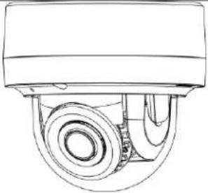 | 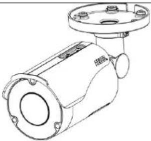 | 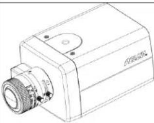 | 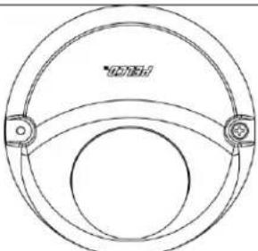 |
| IMP131-1ERSIMP231-1ERSIMP331-1ERSIMP231-1ISIMP331-1ISIMP531-1ESIMP531-1ISIMP231-1ESIMP331-1ESIMP131-1IRSIMP231-1IRSIMP331-1IRSIMP531-1ERSIMP531-1IRS | IBP131-1ERIBP231-1ERIBP331-1ERIBP531-1ERIBP232-1ERIBP532-1ERIBP235-1ERIBP335-1ER | IXP13IXP23IXP33IXP53 | IWP133-1ERSIWP233-1ERSIWP232-1ERSIWP234-1ERSIWP236-1ERSIWP333-1ERSIWP532-1ERSIWP533-1ERS |
Contents
Important Notices 4
Regulatory Notices [FCC CLASS A]....4
Radio and Television Interference ....4
Legal Notice [Audio Notice]......4
Video Quality Caution....4
Frame Rate Notice Regarding User Selected Options ....4
Open Source Software 5
Korean Class A EMC....5
ESD Warning 5
Warranty 5
Network Topology Statement....5
Preface....6
1. Installation and Connection ....7
1.1 Installation....7
1.1.1 Network Topology ....7
1.1.2 System Requirements 7
1.2 Connection....9
1.2.1 Default IP address....9
1.2.2 Connecting From a Computer & Viewing Preparation....9
2. Administration and Configuration....11
2.1 Live 11
2.1.1 Zoom and Focus Controls....12
2.1.2 Pixel Count....12
2.1.3 Video Analytics Control 13
2.2 Settings....13
2.2.1 System 14
2.2.2 Network & Security....18
2.2.3 Imaging....31
2.2.4 A/V Streams 42
2.2.5 Event Source....56
2.2.6 Event Handler....63
Pelco Troubleshooting Contact Information 72
Important Notices
REGULATORY NOTICES [FCC CLASS A]
This device complies with Part 15 of the FCC Rules. Operation is subject to the following two conditions: (1) this device may not cause harmful interference, and (2) this device must accept any interference received, including interference that may cause undesired operation.
RADIO AND TELEVISION INTERFERENCE
This equipment has been tested and found to comply with the limits of a Class A digital device, pursuant to Part 15 of the FCC rules. These limits are designed to provide reasonable protection against harmful interference when the equipment is operated in a commercial environment. This equipment generates, uses, and can radiate radio frequency energy and, if not installed and used in accordance with the instruction manual, may cause harmful interference to radio communications. Operation of this equipment in a residential area is likely to cause harmful interference in which case the user will be required to correct the interference at his own expense.
Changes and Modifications not expressly approved by the manufacturer or registrant of this equipment can void your authority to operate this equipment under Federal Communications Commission's rules.
This Class A digital apparatus complies with Canadian ICES-003.
NOTE: Improper use of audio/visual recording equipment may subject you to civil and criminal penalties. Applicable laws regarding the use of such capabilities vary between jurisdictions and may require, among other things, express written consent from the recorded subjects. You are solely responsible for insuring strict compliance with such laws and for strict adherence to any/all right of privacy and personality.
VIDEO QUALITY CAUTION
FRAME RATE NOTICE REGARDING USER SELECTED OPTIONS
Pelco systems are capable of providing high quality video for both live viewing and playback. However, the systems can be used in lower quality modes, which can degrade picture quality, to allow for a slower rate of data transfer and to reduce the amount of video data stored. The picture quality can be degraded by either lowering the resolution, reducing the picture rate, or both. A picture degraded by having a reduced resolution may result in an image that is less clear or even indiscernible. A picture degraded by reducing the picture rate has fewer frames per second, which can result in images that appear to jump or move more quickly than normal during playback. Lower frame rates may result in a key event not being recorded by the system.
Judgment as to the suitability of the products for users' purposes is solely the users' responsibility. Users shall determine the suitability of the products for their own intended application, picture rate and picture quality. In the event users intend to use the video for evidentiary purposes in a judicial proceeding or otherwise, users should consult with their attorney regarding any particular requirements for such use.
OPEN SOURCE SOFTWARE
This product includes certain open source or other software originated from third parties that is subject to the GNU General Public License (GPL), GNU Library/Lesser General Public License (LGPL) and different and/or additional copyright licenses, disclaimers, and notices.
The exact terms of GPL, LGPL, and some other licenses are provided to you with this product. Please refer to the exact terms of the GPL and LGPL at http://www.fsf.org (Free Software Foundation) or http://www.opensource.org (Open Source Initiative) regarding your rights under said license. You may obtain a complete corresponding machine-readable copy of the source code of such software under the GPL or LGPL by sending your request to digitalsupport@pelco.com; the subject line should read Source Code Request. You will then receive an email with a link for you to download the source code.
This offer is valid for a period of three (3) years from the date of the distribution of this product by Pelco.
KOREAN CLASS A EMC
WARNING: This product is sensitive to Electrostatic Discharge (ESD). To avoid ESD damage to this product, use ESD safe practices during installation. Before touching, adjusting or handling this product, correctly attach an ESD wrist strap to your wrist and appropriately discharge your body and tools. For more information about ESD control and safe handling practices of electronics, please refer to ANSI/ESD S20.20-1999 or contact the Electrostatic Discharge Association (www.esda.org).
WARRANTY
For information about Pelco's product warranty and thereto related information, refer to www.pelco.com/warranty.
NETWORK TOPOLOGY STATEMENT
IMPORTANT NOTE. PLEASE READ. The network implementation is shown as a general representation only and is not intended to show a detailed network topology. Your actual network will differ, requiring changes or perhaps additional network equipment to accommodate the system as illustrated. Please contact your local Pelco representative to discuss your specific requirements.
Preface
This operations manual is to be used as a reference for the manipulation of the camera unit including features, functions, and a detailed explanation of the menu tree.
This manual provides the following information:
- Administration and Configuration: The main menu navigation and controls explanations.
1. Installation and Connection
1.1 Installation
1.1.1 Network Topology
The unit, which is equipped with Ethernet RJ-45 network interface, can deliver video images in real time via either Internet or Intranet. Please refer to the skeleton drawings shown below to aid your understanding.
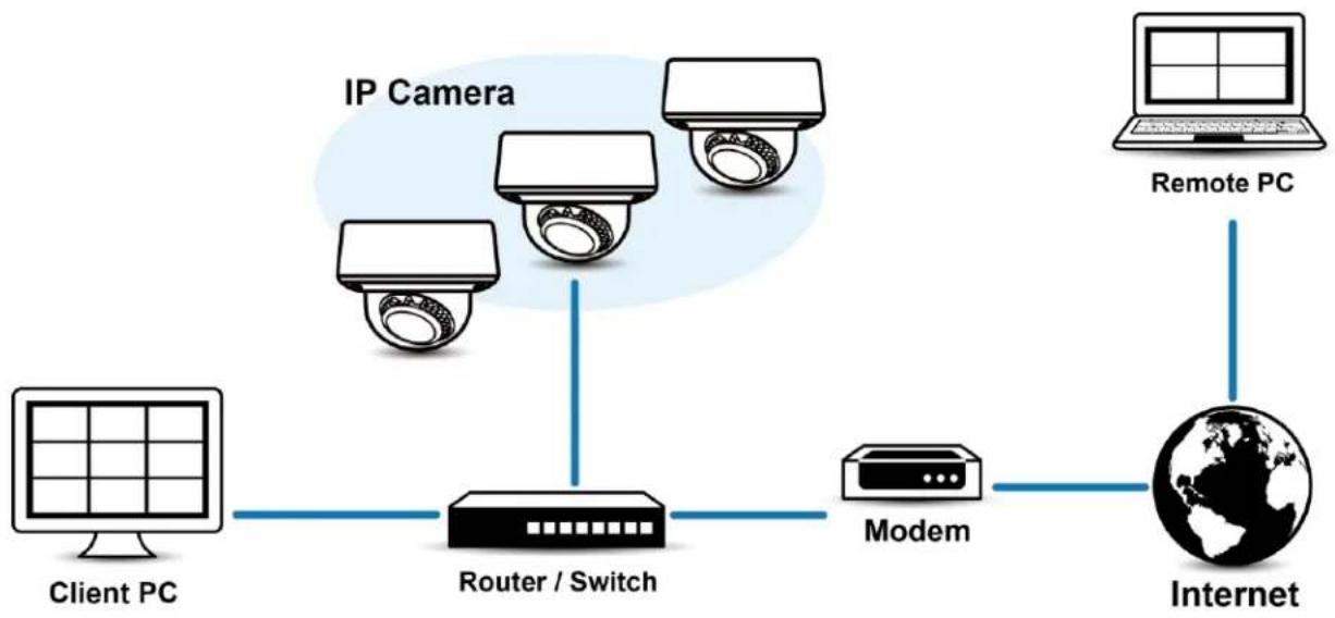
flowchart
graph LR
    A["Client PC"] --> B["Router / Switch"]
    C["IP Camera"] --> B
    D["Modem"] --> E["Internet"]
    F["Remote PC"] --> E
FIGURE 1-1: NETWORK TOPOLOGY
1.1.2 System Requirements
The table below lists the minimum requirements to implement and operate a unit. Network and processor bandwidth limitations might cause the video stream to pause or appear pixilated when additional Web-interface users connect to the camera. Decrease the images per second (ips), resolution, compression, or bit rate settings of the Web interface video streams to compensate for network/processor limitations.
TABLE 1-1: SYSTEM REQUIREMENTS
| System Hardware | |
| CPU | Intel® Pentium® 4 microprocessor, 2.4GHz or equivalent |
| RAM | 1 GB or above |
| Monitor | Minimum of 1024 x 768 resolution, 16- or 32-bit pixel color resolution |
| Network Interface | 100 megabits (or greater) |
| System Software | |
| Operating System | Microsoft Windows 8/7 |
| Browser | Google Chrome 61.0 (or later), Internet Explorer® 8.0 (or later) or Firefox 3.5 (or later) |
| Media Player | VLC: 1.1.11 or above, QuickTime: 7 or above |
| Unit | |
| Power Supply | PoE / AC 24V /DC 12V |
Note
- All the installation and operations should comply with your local electricity safety rules.
- This product is not compatible with QuickTime version 7.6.4 for Windows XP or Windows Vista. If you have this version installed on your PC, you will need to upgrade to QuickTime version 7.6.5.
- Network and processor bandwidth limitations might cause the video stream to pause or appear pixelated when additional Web-interface users connect to the camera. Decrease the images per second (ips), resolution, compression, or bit rate settings of the Web interface video streams to compensate for network or processor limitations.
1.2 Connection
1.2.1 Default IP address
The unit's default IP address is 192.168.0.20 and sub mask is 255.255.255.0. When setting default IP address of 192.168.0.20 the camera will check to see if that address is already in use and will bump the last octet of the address by 1 if it is. The bump last octet of IP Address by 1 will continue until an unused IP address is found.
However, if you have a DHCP server in your network, the unit would obtain an IP address automatically from the DHCP server so that you don't need to change the camera's IP address. The factory default is DHCP On and 192.168.0.20 assignment only occurs when camera is set for DHCP but a DHCP server does not respond to request for an IP address.
1.2.2 Connecting From a Computer & Viewing Preparation
1.2.2.1 Using Pelco Device Utility Software to Get Camera's IP Address
Pelco Device Utility software is a utility program that helps users to manage and configure the camera. Use the utility to find the IP address since the default option is to obtain an IP address via DHCP and therefore the IP address will NOT be known. Steps to get the utility program running are listed below.
- Finish installing the Device Utility to the computer according to the installation instructions.
- Log in to the Device Utility by entering the camera's User name and Password. In the window, enter the previously created user name and password, then click Enter button to log in.
- In the Manage Devices page, you can click Refresh Device List or Add New Device to search for the devices.
- From the Device List, you can get series information about camera, IP Address included.
For more information about using the Device Utility, click this green icon "?" on the upper-right corner of the Device Utility page.
1.2.2.2 Connecting from a computer
- Check if there is networking available between the unit and the computer by executing ping the default IP address. Start a command prompt (Windows: from the Start Menu, select Program. Select Accessories and choose Command Prompt.), and type "Ping 192.168.0.20". If the message "Reply from..." appears, it means the connection is available.
- Start Internet Explorer and enter IP address: 192.168.0.20. A login window should pop up. In the window, enter the created friendly user name and created password to log in.
NOTE: If you do not know the camera's IP address, you can locate it using the Pelco Device Utility software (refer to 2.4.2.1 Using Pelco Device Utility Software to Get Camera's IP Address).
Further administration on the unit can be found in "3. Administration and Configuration".
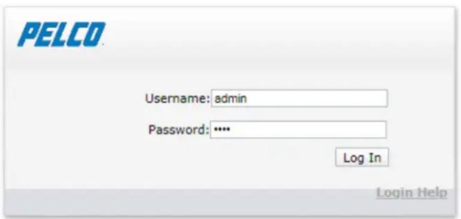
FIGURE 1-2: LOGIN WINDOW
NOTE: When connecting to the camera for the first time, or after restoring the camera's setting back to factory default, a user account must be created to enable access to video from the camera.
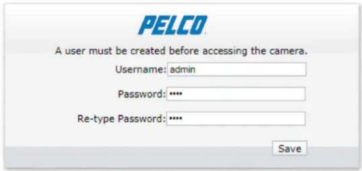
FIGURE 1-3: USER CREATION
1.2.2.3 Viewing Preparation
Images of the unit can be viewed through Microsoft Internet Explorer 9 or later. Before viewing, follow these steps to enable the display.
- Enable Cookies On the Privacy tab, move the settings slider to Low or Accept All Cookies.
- Change Security in Internet options and click Custom Level to open the Security Settings – Internet Zone screen.
NOTE: If the camera operates inside of the intranet, click the Intranet icon. If the camera operates outside of the intranet, click the Internet icon.
- Scroll down to the ActiveX controls and plug-ins radio buttons and set as follows:
• 【Download signed ActiveX controls】→ Prompt (recommended)
• 【Download unsigned ActiveX controls】→ Prompt
• 【Automatic prompting for ActiveX controls】→ Enable
• 【Run ActiveX controls and plug-ins】→ Enable
• 【Script ActiveX controls marked safe for scripting*】→ Enable
- Press OK to save the settings.
- Close all Microsoft Internet Explorer Windows and restart a new window. This will allow the new settings taking effect.
- Type your setting IP address into the browser.
- Then you should be able to see the camera image screen.
2. Administration and Configuration
2.1 Live
Simply click on Live on the top right side of the browser window while accessing the IP address of the unit, and a live video is displayed directly in the browser window. When clicked on Settings, a window will pop up for configuring "System", "Network & Security", "Imaging", "A/V Streams", "Event Source" and "Event Handler". Please refer to 2.2 Settings on page 13 for more information. The current logged in identity appears to the right of the Help. Click on Logout admin of the administration window and configuration will return to the camera image screen.
* Figures of 3. Administration and Configuration are taken from the 3MP model for web interface introduction purposes. Options within each item may differ slightly among series products and the differences will be marked in a NOTE.
Options on the Live window include:

Maximize Viewing Area: Scales the image to the full size of the browser. To resize the video pane to normal view, click the Show Toolbar button in the upper-right corner of the window.

Open Stream in New Window: Opens the video in a scalable, independent window. Opening the video in a separate window allows you to view the video while other applications are running. This window can be minimized, maximized, or closed using the title bar buttons of the active window. The window can also be resized to your specifications by dragging the lower-right corner of the window.

Snapshot: Capture a screenshot of what appears currently on the live view image. A prompt message appears, after clicking the icon, to allow user to either open the screenshot or save the screenshot to a designated path.
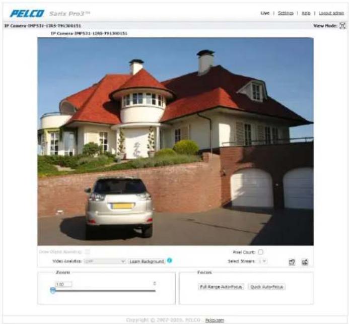
FIGURE 2-1: LIVE VIEW
2.1.1 Zoom and Focus Controls
Zoom
- Zoom In: Click and drag the slider right to zoom the lens in.
- Zoom Out: Click and drag the slider left to zoom the lens out.
Focus
Full Range Auto-Focus: Click the button for the camera to start a full-range search to find the optimal focal point for the scene.
- Quick Auto-Focus: Click the button for the camera to start a quick search to find the optimal focal point for the scene.
NOTE: The Zoom function is available in motorized models only.
2.1.2 Pixel Count
When setting up the camera, use pixel count technology to validate your operational requirements.
Your operational requirements could be identification of an object of known size while being able to see as much of the scene as possible.
Pixel count is the rectangular aid displayed in the camera's live view, with a counter showing the box's width and height. Pixel count can be adjusted and moved around the image with drag-and-drop.
For example; to ensure the identification of a 1 meter object in a scene, you can set pixel count to 500 pixels, and then adjust the camera so that the object fits inside the pixel counter.
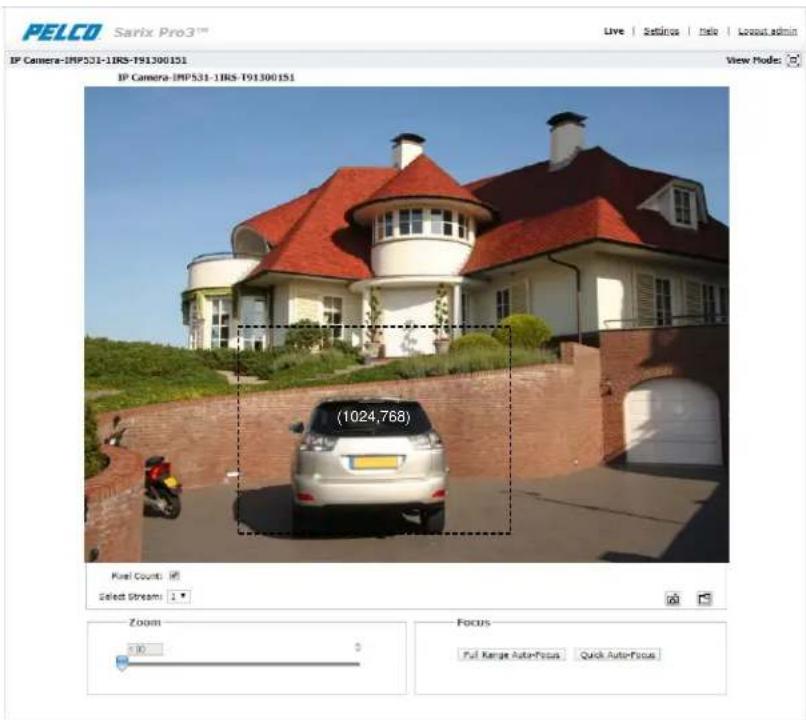
FIGURE 2-2: PIXEL COUNT SETTINGS
Pixel Count: Check Pixel Count button to enable pixel count feature for selected stream.
Select Stream: Selects the video stream that is displayed in live view (primary, secondary or tertiary) to be used with pixel count technology.
2.1.3 Video Analytics Control
Draw Object Bounding
- Draw Object Bounding: Check this box to allow camera to activate motion detection and draw an area around the detected object. This function can be use only when a VA function is activated.
Video Analytics
- Select a Video Analytics (VA) function from the dropdown menu. Make sure that the selected VA function is enabled in "Event Source" section. When "Off" is selected, it means that the camera is not performing any VA function.
Relearn Background
- Relearn Background: Click this button to save the current background that later will be used to compare future backgrounds for Video Analytics and Sabotage Detection purposes.
2.2 Settings
Click on Settings, a window will pop up for configuring "System", "Network & Security", "Imaging", "A/V Streams", and "Events".
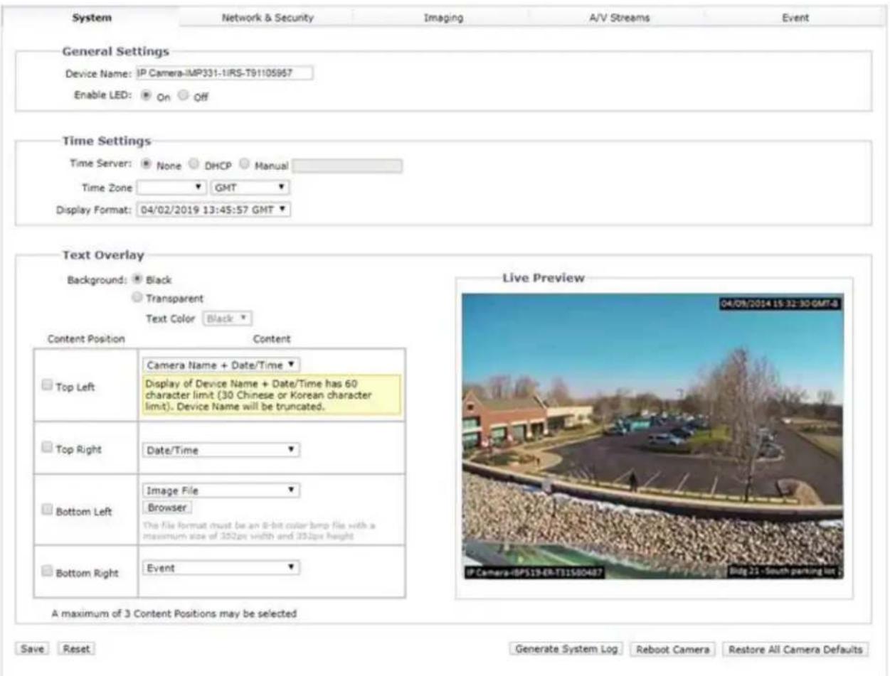
FIGURE 2-3: SYSTEM SETTINGS
2.2.1 System
Use the System tab to change the device name, configure the time settings, set up the text overlay for the live view, get backup, display system information, update firmware version, get information about inserted SD card and pixel count. You can also use the System tab to generate a system log, reboot the camera, or to restore the camera's factory default settings.
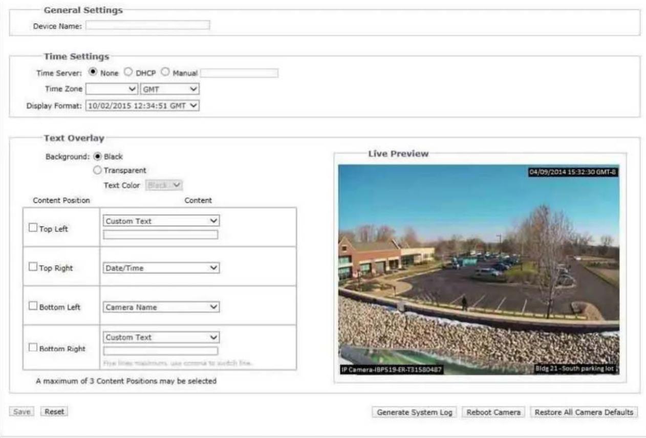
FIGURE 2-4: SYSTEM SETTINGS
Generate System Log
- Click the System tab.
- Click the Generate System Log button to create a system log that can be used by Pelco Product Support for troubleshooting.
Contact Pelco Product Support at 1-800-289-9100 (USA and Canada) or +1-559-292-1981 (international).
Reboot Camera
- Click the System tab.
- Click the Reboot Camera button to restart the camera. Rebooting the camera does not change the configured camera settings.
This process cannot be undone; all user and custom settings will be lost.
-
Click the System tab.
-
Click the Restore All Camera Defaults button to restore the camera's factory default settings.
NOTE: If the camera is not connected to a Dynamic Host Configuration Protocol (DHCP) network, the IP address settings for the camera will be lost and the server will not recognize the camera. DHCP On is the default setting for the camera IP address.
2.2.1.1 General Settings
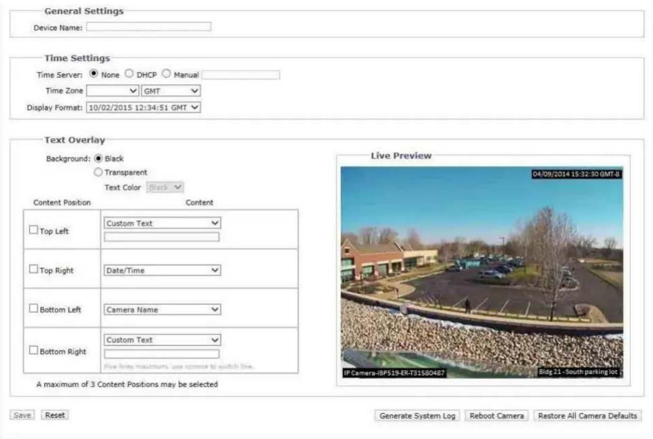
FIGURE 2-5: GENERAL SETTINGS
Device Name
To change the Device Name, follow these steps:
- Click the Device Name box and highlight the text.
- Type a user-friendly name into the Device Name box (2 to 64 characters). A user-friendly name makes it easier to recognize the device on the network. Examples of user-friendly names are Front Door, Lobby, or Parking Lot.
- Click Save to save the new device name, or click Reset to restore to the previously saved device name.
Time Settings
If the camera is connected to a Dynamic Host Configuration Protocol (DHCP) network that has time server properties configured, the camera will synchronize automatically with the time server. If the DHCP network's time server properties are not configured, or the network does not have a time server, you need to configure the time settings manually.
-
Type the IP address of the time server in the Time Server field. The time server is an external server that uses Network Time Protocol (NTP) to synchronize the camera date and time settings.
-
Select the Time Zone option. Select the continent and the region that are closest to the camera's location from the Time Zone drop-down menus.
NOTE: If your location observes a form of daylight saving time, the system will automatically change the time on the associated dates. - Select the format in which the date and time will appear from the Display Format drop-down field if you have opted to show the Date/Time Overlay.
- Click the Save button to save the settings, or click the Reset button to clear all of the information you entered without saving it.
Text Overlay
- Configure the text overlay settings:
- Background: Set the background color for the text overlay as black or transparent. Text color for the transparent background can be also customized from the drop-down menu when the transparent background option is selected. - Content: Six content options can be selected to display from the drop-down menu: Date/Time, Camera Name, Camera Name + Date/Time, Custom Text, Image and Event. The blank text field, which is for inputting desired text by users, shows only when Custom Text option is selected.
NOTE: Multiple content options can display simultaneously.
- Content Position: Four positions can be selected to display content overlays: Top Left, Top Right, Bottom Left, and Bottom Right. For Bottom Right position, a note that informs that a maximum of five lines with commas to switch between them would appear under the text field once Custom Text option is selected.
NOTE: A maximum of 3 content positions can be displayed simultaneously.
- Click the Save button to save the settings, or click the Reset button to clear all of the information you entered without saving it.

FIGURE 2-6: BACKUP AND RESTORE SETTINGS
Backup
Once the camera settings have been configured for optimal scene display, use the backup feature to save the camera settings.
Restore
If the camera settings are changed and inadvertently result in a less desirable image, use the restore setting to restore the camera to the previously saved settings.
NOTE: This feature is not intended for the configuration of multiple units or for firmware upgrades.
2.2.1.3 Firmware
System Information
The System Information page fields are read-only and include the firmware version, hardware version, model number, and serial number of the system are revealed here as below figure. This information is typically required by Pelco Product Support for troubleshooting purposes.
| System Information | |
| Firmware Version: 02.26.1.8.796 | |
| Hardware Version: 0000-A1.1-90327 | |
| Model Number: IMP531-1IRS | |
| Serial Number: T91300151 | |
FIGURE 2-7: SYSTEM INFORMATION
Firmware Update
Users can update system firmware if available. Ensure a user has been created before updating camera's firmware. All camera motions will shut down during firmware update. Please close any other screens before a firmware update. Never disconnect power or LAN cable during the firmware update process. Disconnecting power during a firmware update will cause the update to fail. It takes approximately 3 minutes for the unit to reboot after firmware update process.

FIGURE 2-8: FIRMWARE UPDATE
2.2.1.4 Storage Management
Device Information
The detailed information of an inserted SD card will be shown in this page where the device type, total capacity, free space and status are presented explicitly for users to preview.

FIGURE 2-9: STORAGE MANAGEMENT SETTINGS
Device Setting
The "Format Device" function is deployed here for further employment. Select either the "vFAT" or "ext4" option from the Format Device dropdown menu, depending on preferred preference, and click on "Format" button to format an SD card.
2.2.2 Network & Security
Use the Network tab to change the camera's general network settings, select the Transport Layer Security(TLS) settings, enable Secure Shell (SSH), configure 802.1x port security settings, choose SNMP Server, Firewall mode, enable FTP access to this camera, activate RTP stream settings and VMS Connectivity with the specific server.
NOTE: Other underlying protocols such as NTCIP 1205, ARP, RTCP, and WS-Discovery are supported by all models.
NOTE: Enabling SNMP protocol (refer to 2.2.2.6 SNMP) will automatically enable NTCIP 1205.
2.2.2.1 Network
Set the General Network Settings for network communication settings.


Save Reset
FIGURE 2-10: GENERAL NETWORK SETTINGS
System Settings
Settings under the System Settings are Hostname, HTTP Port, HTTPS Port, and RTSP Port. Contact your network administrator before changing port settings to ensure that your port settings do not conflict with your network infrastructure.
- Hostname
- Click in the Hostname box and highlight the text.
- Type a user-friendly name into the Hostname box (1 to 21 characters) using any combination of alphanumeric characters. A user-friendly name makes it easier to recognize the device on the network.
- Click the Save button to save the settings, or click the Reset button to clear all of the information you entered without saving it.
- HTTP Port
NOTE: The HTTP port number must remain at the default setting (80) when connecting to a Pelco video management system (VMS) platform. If connecting to a Pelco VMS, do not change the HTTP port setting.
- Click in the HTTP Port box and highlight the text.
- Type the new port number in the HTTP Port field. The default port for HTTP communications is 80.
- Click the Save button to save the settings, or click the Reset button to clear all of the information you entered without saving it.
- HTTPS Port
NOTE: The HTTPS port is not configurable unless you have set TLS Mode to Optional or Required and installed a security certificate.
- Click in the HTTPS Port box and highlight the text.
- Type the new port number in the HTTPS Port field. The default port for HTTPS communications is 443.
- Click Save. If you have changed the setting in error, you can click reset to revert to the previously saved setting.
- RTSP Port
- Click in the RTSP Port box and highlight the text.
- Type the new port number in the RTSP Port field. The default port for RTSP communications is 554.
- Click the Save button to save the settings, or click the Reset button to clear all of the information you entered without saving it.
IPv4 Settings
Enable or disable the Dynamic Host Configuration Protocol (DHCP) server. DHCP automatically assigns an IP address to the device if there is a DHCP server on the network.
- If DHCP is set to On, the IP address, subnet mask, gateway, and DNS server settings are read-only text.
- If DHCP is set to Off, these settings must be manually changed.
Change the following network settings as required:
- IP Address: The address of the camera connected to the network.
- Subnet Mask: The address that determines the IP network that the camera is connected to (relative to its address).
- Gateway: The router that accesses other networks.
- DNS Servers: The addresses of the dedicated servers that translate the names for Web sites and hostnames into numeric IP addresses.
- Click the Save button to save the settings, or click the Reset button to clear all of the information you entered without saving it.
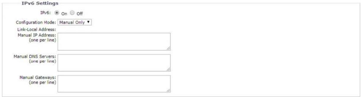
Configuring IPv6 Settings
Your Sarix device supports IPv6 in conjunction with IPv4 configurations; the device does not support IPv6-only network deployments. The device will accept up to sixteen IPv6 addresses, three IPv6 DNS servers, and three IPv6 gateways.
There are two configuration modes for IPv6 address assignments:
Auto: Enables automatic configuration using router advertisement. Additional configuration can be provided over DHCPv6 (if available on your network). Selecting Auto mode still allows you to manually configure additional IPv6 addresses, DNS servers, and gateways.
Manual Only: Provides a link-local IPv6 address for the device and allows you to assign up to 16 static IPv6 addresses to the device.
- Place your mouse pointer over the Network tab.
- Select General from the drop-down menu.
- Select On for IPv6.
- Select a Configuration Mode from the drop-down box. Selecting Auto allows the device to configure the remaining IPv6 settings automatically, rendering the remaining steps optional.
- (Optional) Provide static, unicast addresses in the Manual IP Addresses box. Each address requires a prefix, and it must be input using the format prefix/IPv6Address. Manual IP addresses without prefix information will be rejected.
- (Optional) Provide the addresses of DNS servers that are not configured automatically in the Manual DNS Servers box.
- (Optional) Provide the addresses of gateways that are not configured automatically in the Manual Gateways box.
NOTES:
- The device will not accept multicast, localhost, or undefined IPv6 addresses.
- Link-local addresses are not supported for DNS.
- Manually specified DNS servers supersede automatically discovered DNS servers.
- Manually specified DNS servers are not validated by the device; verify any manually specified DNS servers before saving IPv6 settings.
- Manually specified gateways must be on the same network as the devices' IPv6 addresses. Behavior for a gateway that is not on the same network as the device's IPv6 addresses is undefined.
- Some video management systems (VMS), including Pelco VMS systems, do not support connections to cameras and encoders over IPv6.
2.2.2.2 Users & Security
Use the Users & Security tab to create and manage user accounts and to change the way the camera manages the user settings.
User Management
User accounts are created to limit the permissions of individuals who are logged onto the camera. The User Management page also includes four predefined access level settings that include Administrators, Managers, Operators, and Viewers permissions.
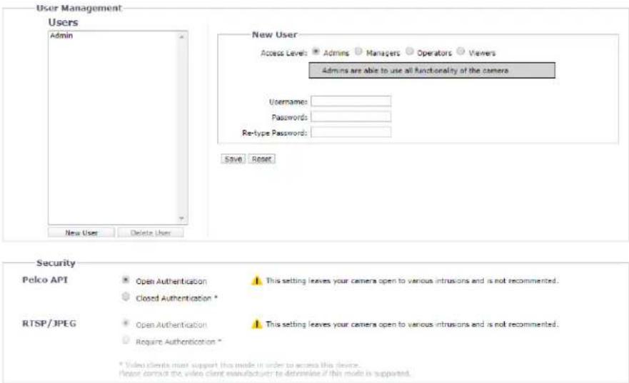
FIGURE 2-11: USERS & SECURITY
Creating a New User
Click New User button below the left box and Select the Access Level for the new user.
- Access Level
-
Select the Access Level for the user.
-
Admins: This is the only defined group that cannot be deleted. This group has access to all permissions.
- Managers: This defined group can be modified or deleted. This group has access to all permissions except the permissions of access to the Users page and the restore factory defaults.
- Operators: This defined group can be modified or deleted. The default permissions for this group are video stream view, PTZ manipulation as well as the use of API.
NOTE: PTZ manipulation permission varies by applicable models.
- Viewers: This defined group can be modified or deleted. The default permissions for this group are limited within the video stream view and the use of API.
- Click the Save button to save the settings and create a new user. The new user profile appears in the box on the left side of the page. Click the Reset button to clear all of the information you entered without saving it.
- Username
Click in the Username box and type a user name (2 to 23 alphanumeric characters). User names are case-sensitive.
- Password
Click in the Password box and type a password (4 to 16 alphanumeric characters). Passwords are case-sensitive.
- Re-type Password
Click in the Retype Password box and retype your password.
Click the Save button to save the settings and create a new user (the new user profile appears in the box on the left side of the page), or click the Reset button to clear all of the information you entered without saving it.
Deleting a User
-
Click the user profile that you want to delete from the defined users section located in the box on the left side of the page.
-
Click the Delete User button. A dialog box appears with the message "Are you sure you want to delete this user?"
- Click OK. The user profile is deleted from the defined user profiles section.
NOTE: The default "admin" user cannot be deleted.
Security
- Pelco API
Selecting "Closed Authentication" will request video clients to conform to Pelco API (Application Programming Interface) protocol in order to access to the camera, while selecting "Open Authentication" will make API protocol of the camera fully open to various intrusions, which is not suggested due to security concerns.
- RTSP/JPEG
Selecting “Require Authentication” will request video clients to conform to RTSP (Real Time Streaming Protocol) or JPEG protocol in order to access to the camera, while selecting “Open Authentication” will make RTSP/JPEG protocol of the camera fully open to various intrusions, which is not suggested due to security concerns.
2.2.2.3 TLS
To ensure security on the Internet, all Web browsers provide several security levels that can be adjusted for sites that use TLS technology to transmit data. TLS encrypts communications, making it difficult for unauthorized users to intercept and view user names and passwords.
TLS requires signed certificates to determine if the Web browser accessing the camera has the required authentication. The camera can generate a certificate signing request (CSR) that can be sent to a certificate authority for a signature (for example, VeriSign®), or it can generate a self-signed certificate using the Generate Self-Signed Certificate option.

FIGURE 2-12: TLS CONFIGURATION
TLS Configuration
Select one of the following modes:
- Required: A signed Transport Layer Security (TLS) certificate must be installed, and a secure URL that begins with the protocol name "https:" must be used to access the camera. Sensitive data is always encrypted during transmission. A URL that begins with the "http:" protocol rather than the "https:" protocol will be redirected to the secure URL automatically.
- Optional: A signed TLS certificate must be installed, but a secure URL that begins with the protocol name "https:" is optional when accessing the camera. You can also access the camera using a standard URL with the "http:" protocol, but sensitive data is not encrypted during transmission. To ensure that sensitive data is encrypted, you must use a secure URL with the "https:" protocol.
- Disabled (default): Turns off access to the Web client through TLS. Sensitive data will not be encrypted during transmission.
NOTE: If the TLS mode is set to disabled, you cannot access the camera using a URL that begins with an "https:" protocol. Your Web browser displays an error message if you do not type the camera URL correctly.
Refer to the following sections for more information:
- Generating Self-Signed Certificate
- Generating Certificate Request
Certificate
- Generating Self-Signed Certificate
- Click the Install New Certificate button located at the bottom of the TLS Configuration page. The Select Certificate Install Method option buttons appear on the page.

FIGURE 2-13: SELECT CERTIFICATE INSTALL METHOD OPTION
- Select the "Generate Self-signed Certificate" option, and then click Next. The "Self-signed Certificate Information Form" opens.
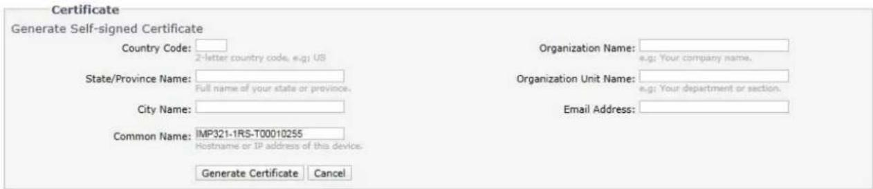
FIGURE 2-14: GENERATING SELF-SIGNED CERTIFICATE CONFIGURATION
- Fill in all of the fields, and then click Generate Certificate. The following progress message appears on the page: "Loading data..." After a while, the certificate is uploaded to the device.
- After the certificate is uploaded, select the desired mode.
- Click Save.
NOTE: Self-signed certificates are valid for one year. The certificate's expiration date is listed in the Installed Certificate information section. If the certificate has expired and you attempt to access the camera using a secure URL, the Web browser displays a message. Repeat this procedure to generate and upload a new certificate.
- Generating Certificate Request
- Click the Install New Certificate button located at the bottom of the TLS Configuration page. The Select Certificate Install Method option buttons appear on the page.
- Select Generate Certificate Request, and then click Next. The "Certificate Request Form" opens.
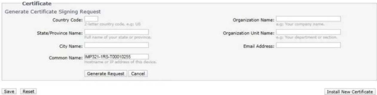
FIGURE 2-15: GENERATING CERTIFICATE REQUEST
- Fill in all of the fields, and then click Generate Request. The following progress message appears on the page: "Generating certificate signing request, please wait..."
- Send the CSR, which looks like an encrypted block of undecipherable text, to a third-party certificate authority of your choice for a signature.
- After you receive the signed certificate, click the Install Certificate button to upload the signed certificate to the device.
- After the certificate is uploaded, select the desired mode.
- Click Save.
NOTE: Depending on the third-party certificate authority that signed your certificate, you might need to renew your certificate after a specified amount of time. Consult the certificate authority for more details.
- Upload Certificate
- Click the Install New Certificate button located at the bottom of the TLS Configuration page. The Select Certificate Install Method option buttons appear on the page.
- Select Upload Certificate, and then click Next. The "Certificate" opens.

FIGURE 2-16: UPLOAD CERTIFICATE
- Choose the Certificate you want to upload and then click Upload button. The following progress message appears on the page: "Loading data..."
- After the certificate is uploaded, select the desired mode.
- Click Save.
- Delete Certificate
- Once you successfully upload a certificate, Delete Certificate button will appear at the bottom of the TLS Configuration page.
- If you want to delete the certificate, click the Delete Certificate and the following progress message appears on the page: "Deleting certificate file..."
- Click Save.
2.2.2.4 SSH
SSH is a user-enabled protocol that allows Pelco Product Support to log on to and service the camera for advanced troubleshooting purposes.
From this page, users with the appropriate permissions can enable or disable SSH access to the camera.

FIGURE 2-17: ENABLING SECURE SHELL
SSH Settings
- Select the Enabled check box.
NOTE: It is not possible to enable SSH and SFTP at the same time.
- Click in the Password box and type a password (4 to 16 alphanumeric characters). Passwords are case-sensitive.
NOTE: The default username is "root" and cannot be changed. The username and password are required when accessing the camera through a third-party SSH client.
- Click in the "Re-type Password" box and retype your password.
- Click the Save button to save the password and enable SSH, or click the Reset button to clear all of the information you entered without saving it.
2.2.2.5 802.1x
802.1x is a port security that authenticates devices that want to establish a point-to-point access through a wired or wireless port using Extensible Authentication Protocol (EAP). This port-based authentication method prevents unauthorized access to a Local Area Network (LAN) through a physical port. For example, when a device is connected to a network port, the network switch will ask the device for authentication.
If the credential is accepted when the device sends a credential to the network switch, the network switch will open the port for normal use.
If authentication fails, the device is prevented from accessing information on the port.

FIGURE 2-18: CONFIGURING THE 802.1X PORT SECURITY SETTINGS
802.1x Port Security
WARNING: To prevent network conflicts, contact your network administrator before configuring the 802.1x port security settings.
- Select the On option for the 802.1x Port Security. The default setting for 802.1x is Off.
- Select the Extensible Authentication Protocol (EAP) method from the Protocol drop-down menu. Supported EAP
methods include EAP-MD5, EAP-TLS, EAP-TTLS, and EAP-PEAP.
- Type the information required for the selected 802.1x authentication method.
- Connect the PC to an 802.1x secured switch that has the same EAP method.
- Click the Save button to save the settings, or click the Reset button to clear all of the information you entered without saving it.
2.2.2.6 SNMP
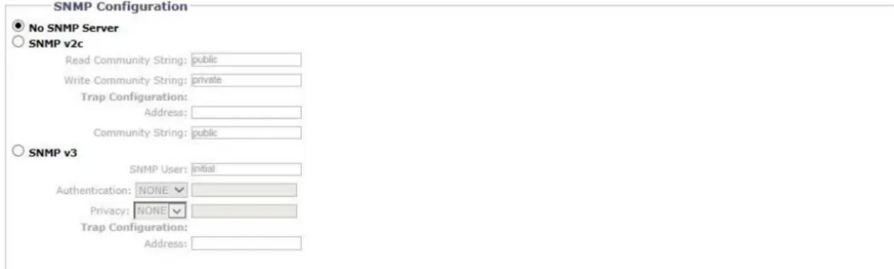
SNMP is an application layer protocol used to manage TCP/IP-based networks from a single workstation or several workstations. The camera supports SNMP versions 2c and 3 and can be configured to send data using a trap.
Save Reset
FIGURE 2-19: SNMP CONFIGURATION
SNMP Configuration
WARNING: The Simple Network Management Protocol (SNMP) settings are advanced controls. Consult your network administrator to obtain the required information to configure SNMP settings.
- No SNMP Server
None disables the SNMP configuration and is the default setting.
- CONFIGURING SNMP V2C
- Select V2c as the SNMP Version.
- Type the community name in both the Read and Write Community String box. The default name for each is "public" and "private" respectively.
-
Configure the Trap Configuration settings.
-
Address: Type the host name or IP address of the recipient of the trap message.
• Community String: Type the name of the community that should receive the trap message. -
Click the Save button to save the settings, or click the Reset button to clear all of the information you entered without saving it.
- CONFIGURING SNMP V3
- Select V3 as the SNMP Version.
- Enter the SNMP user name in the SNMP User field.
-
Select the encryption algorithm for authentication from the Authentication drop-down menu: None, MD5, or SHA. If you use authentication method MD5 or SHA, type a password in the text box to the right of the selected Authentication encryption.
-
Select the privacy encryption algorithm setting from the Privacy drop-down menu: None, DES, or AES. If you use privacy method DES or AES, type a password in the text box to the right of the selected Privacy encryption.
- Configure the address for the Trap Configuration. The Address is the host name or IP address of the recipient of the trap message.
- Click the Save button to save the settings, or click the Reset button to clear all of the information you entered without saving it.
NOTE: SNMP V2c and SNMP V3 configuration settings are independent of each other, but only one SNMP version can be active at a time.
2.2.2.7 Firewall
Set the Firewall function. A firewall is a system or group of systems that manages access between two networks.
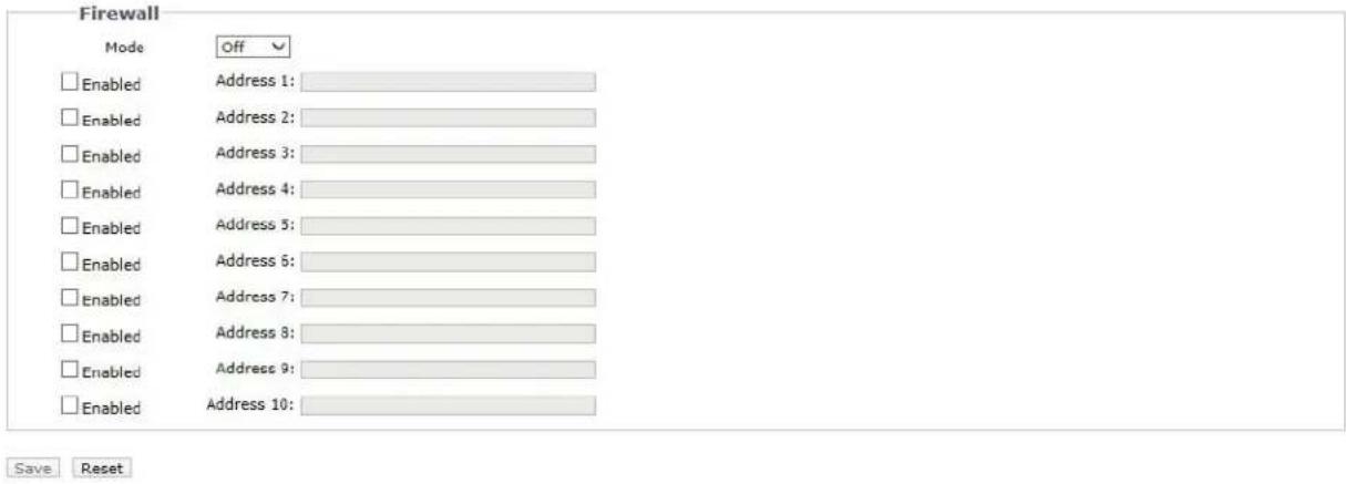
FIGURE 2-20: FIREWALL CONFIGURATION
Firewall
- Select Allow or Deny mode to enable this function. The default setting is Off.
- Check Enabled to enter IP address in the Address field. Up to ten addresses can be enabled for entry.
- Click the Save button to save the settings, or click the Reset button to clear all of the information you entered without saving it.
2.2.2.8 FTP
This page will enable or disable FTP and SFTP access to this camera. In this page, users can activate both FTP Server and SFTP Server to access the SD card for recordings. Enabled the FTP and SFTP, and use this function.
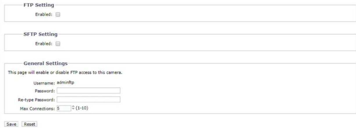
FIGURE 2-21: FTP SETTINGS
FTP Setting / SFTP Setting / General Settings
- Select the Enabled check box to activate the FTP function and/or SFTP function, and follow the following procedures to set up related settings.
NOTE: It is not possible to enable SFTP and SSH at the same time. - Enter a Username if you activated the FTP function.
-
Enter a Password associated with the Username.
-
Re-type Password to confirm it.
-
Set the number of maximum connections by entering a number in the Max Connections field.
NOTE: This is the maximum of FTP Client connections, not the maximum of IE Window's connections.
- Click the Save button to save the settings, or click the Reset button to clear all of the information you entered without saving it.
2.2.2.9 VMS Connectivity
This page relates to the standard protocol that conforms to the regulations of IP security surveillance data transmitting, transferring and monitoring within the PRC (People Republic of China) areas.

FIGURE 2-22: VMS CONNECTIVITY SETTINGS
Endura Connectivity
In order to connect with the Pelco NVR Endura, please choose a communication method to be adopted for connectivity from the following two options:
- Listen for Endura SM system availability broadcast: In general, Endura broadcasts its SM IP Address to the camera so that a stable connection can be maintained between Endura system and the camera.
- Associate with specific Endura SM system: Under certain cases, the camera is unable to receive broadcast from Endura system and therefore is in need of a SM IP Address assigned specifically by user for connectivity.
2.2.2.10 DDNS
Dynamic Domain Name Server (DDNS) is the system that can automatically upgrade DSN records without further manual editing in a real time manner, resulting in directing to the web address faster and smoother.

Save Reset
FIGURE 2-23: VMS CONNECTIVITY SETTINGS
General Settings
Enable: On/ Off
● Provider: DynDNS/ No-IP/ Two-DNS/ FreeDNS
There are 4 types of DDNS for selection as the following items.
DynDNS: One of the DDNS providers offering service with fee collection.
No-IP: A DDNS provider offering free service. Please register yourself before enabling this type.
Two-DNS: A DDNS provider offering free service. Please register yourself before enabling this type.
FreeDNS: A DDNS provider offering free service. Please register yourself before enabling this type.
- Hostname: Define a specific hostname for DDNS.
- Username: Configure a privileged username for accessing to DDNS.
- Password: Input the password associated with the privileged username.
2.2.2.11 SIP
Session Initiation Protocol (SIP) is a text-based protocol, similar to HTTP and SMTP, for interactive communication sessions between users; allowing sessions with voice and video elements. SIP allows our cameras to make calls.
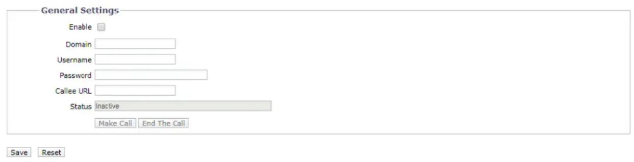
FIGURE 2-24: SIP SETTINGS
General Settings
● Enable: Check the box to enable SIP, allowing the camera to make a call.
- Domain: Enter the domain used for SIP sessions.
- Username: Configure a privileged username for accessing to SIP server.
- Password: Input the password associated with the privileged username for authenticating against the SIP server.
- Callee URL: Enter the URL of the recipient the call from the camera.
● Status: Display the status of SIP session.
● Make Call / End The Call: Click Make Call or End The Call button to start or end call with the associated SIP recipient.
2.2.3 Imaging
Use the Imaging tab to change the camera's general image settings, adjust the camera exposure and white balance, program the focus mechanism, or define window blanking privacy areas.
FIGURE 3-26: IMAGING SETTINGS
2.2.3.1 General
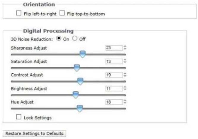
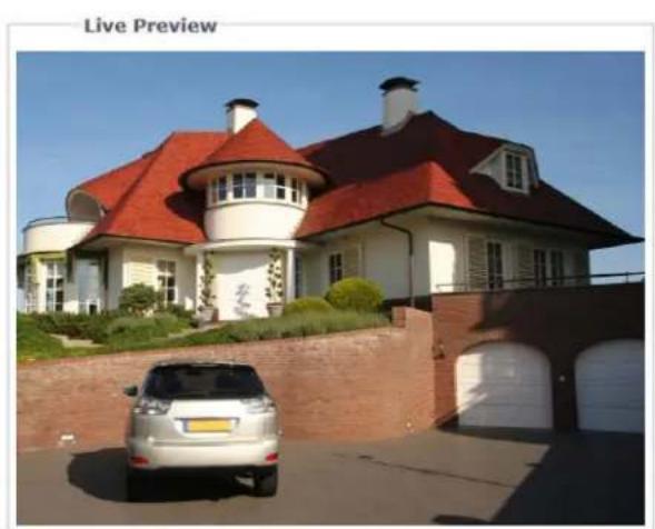
General imaging settings include adjustments for camera orientation and digital processing.
natural_image
Exterior view of a modern house with red-tiled roof and white walls, featuring a silver SUV parked in front (no signage)FIGURE 2-25: GENERAL IMAGING SETTINGS
Orientation
Use this setting when installing the camera in an inverted position. If the orientation is not adjusted, the image will display upside down and mirrored.
Select one of the following options:
- Click the "Flip left-to-right" box to rotate the camera image 180 degrees horizontally.
- Click the "Flip top-to-bottom" box to rotate the camera image 180 degrees vertically.
Digital processing
Digital processing settings can adjust the camera's noise reduction, sharpness, saturation, contrast, brightness and hue.
Move the slider to the left or right to change the following settings:
- 3D Noise Reduction: Enable 3D Noise Reduction to improve video noise in low light scenes. Turn off 3D noise reduction if details are blurred in moving objects.
- Sharpness: Controls the clarity of detail in a scene. Move the slider to the right to increase the sharpness; move the slider to the left to decrease the sharpness. Increasing the sharpness also increases the image noise. The range of adjustment is -100 to 100; the default setting is 0 (zero).
- Saturation: Controls how intense or vivid the colors are in a scene. Move the slider to the right to increase the saturation level; move the slider to the left to decrease the saturation level. The range of adjustment is -100 to 100; the default setting is 0 (zero).
- Contrast: Controls gradations between the darkest and lightest portions of the scene. Move the slider to the right to
increase the contrast; move the slider to the left to decrease the contrast. The range of adjustment is -100 to 100; the default setting is 0 (zero).
- Brightness: Controls the lighting detail in a scene. Move the slider to the right to lighten the image; move the slider to the left to darken the image. The range of adjustment is -100 to 100; the default setting is 0 (zero).
- Hue: Controls the color in a scene. Move the slider to the right to achieve a cool color image; move the slider to the left to achieve a warm color image. The range of adjustment is -100 to 100; the default setting is 0 (zero).
Check Lock Settings box to lock the above Digital processing settings.
2.2.3.2 Exposure
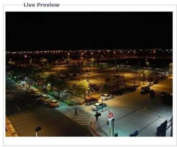
Exposure is the amount of light detected by the camera sensor. A scene with correct exposure settings has adequate detail and contrast between white and dark values. An image with too little or too much exposure eliminates detail in the scene. The camera features Exposure and Day/ Night settings.
natural_image
Nighttime aerial view of a city street intersection with illuminated buildings and vehicles (no visible text or symbols)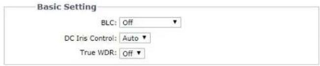
Restore Settings to Defaults
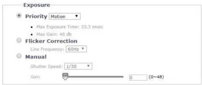
FIGURE 2-26: EXPOSURE SETTINGS
Exposure
- Priority Preset
Select Motion or Low Noise as the exposure priority. The Motion setting increases exposure time to reduce motion blurring in low light. The Low Noise setting decreases exposure time and adjusts frame rate for improved noise reduction in low light scenes.
- Flicker Correction
Flickering by fluorescent light can be reduced by selecting "50Hz" if the power frequency is 50Hz, "60Hz", if 60Hz.
- Manual
Manual is a mode that allows the user to manually control both gain value and shutter speed. Selecting a smaller value like 1/10000 provides the fastest shutter speed and vice versa. The larger the value, the more intensity of lights come into the camera and vice versa. It is recommended for an experienced administrator to adopt this mode.
Basic Setting
BLC
Select an area ranging from Upper, Lower, Central 1/3rd, Central 1/6th, Left, and Right for Backlight Compensation. Backlight Compensation is a function that sets the brightness of a selected area to an optimal level. This function is necessary when an auto iris lens tends to close quickly due to an intense light coming from the back of object in the area
wished to view, resulting in the area being too dark and difficult to see. In this case, users may set the area corresponding to the portion they wish to see.
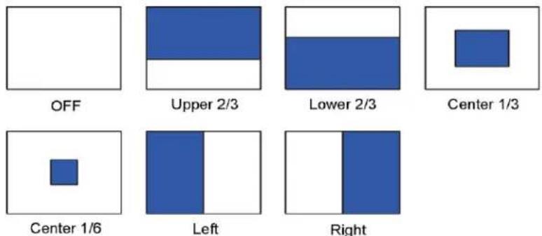
FIGURE 2-27: BLC SETTINGS ILLUSTRATIONS
- DC Iris Control
DC Iris Control, driven by electric currents, is one of the auto iris modes that helps the surveillance camera to automatically adjust its iris opening, for better adaptation to environments with constant changes in light levels. There are 2 options below for selection:
- Auto: Iris opening will alter itself in accordance with the changing light levels within the applied environment to present a better image quality.
- Full: Iris opening will be kept within the maximum value regardless of light levels in environment.
NOTE: The DC Iris Control function is available in DC Iris equipped models only.
- True WDR
Select On to enable True WDR. This technology is intended to provide a clear image even under the backlight circumstance where intensity of illumination can vary excessively; namely both extreme bright and dark areas exist simultaneously in the field of view. True WDR is a sensor-based technology that achieves proper exposure levels by capturing short and long exposures individually and combining them into a single frame to render a superior detail of image quality. Note that when True WDR is enabled, the maximum frame rate will be forcibly decreased to 30fps if it was selected above 30fps originally. NOTE: True WDR is only possible when the Exposure Priority setting is set to Motion.
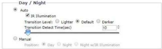
Day/Night
The Day Night Auto mode setting automatically controls the IR cut filter depending on the Transition Level and Transition Detect Time settings.
- Auto
- Transition Level: Determines when the camera changes from day mode (color) to night mode (black-white). Select the "Lighter" transition level setting if you want the camera to change modes at a high lux setting. Use the "Default" setting for normal day/night operation. Use the "Darker" transition level to change modes at a low lux setting.
TABLE 2-1. LUX TRANSITION POINTS FOR INCANDESCENT LIGHTING
| Transition Level Setting | Day to Night Transition Point |
| Lighter | 10 lux |
| Default | 2 lux |
| Darker | 1 lux |
Check the IR Illumination box to enable IR Illumination.
NOTE: The IR Illumination function is available in IR equipped models only.
- Transition Detect Time (sec): Controls the length of time the camera is exposed to a light level before it changes to color or black-white mode.
This setting is useful for dark scenes where a bright light is momentarily introduced in the scene (for example, when a car with its headlights turned on passes the camera scene).
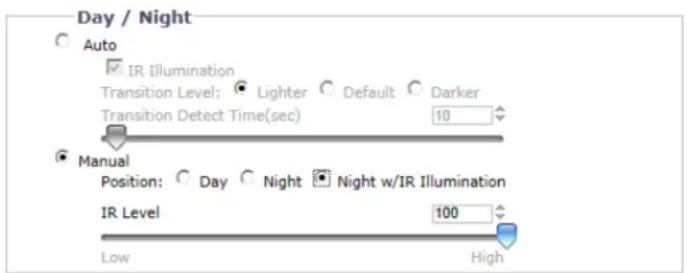
FIGURE 2-28: DAY/NIGHT SETTINGS - MANUAL
- Manual
- Day: If the Day mode is selected, the camera is forced to stay in Day mode all day.
- Night: If the Night mode is selected, the camera is forced to stay in Night mode all day.
- Night w/IR Illumination: If the Night w/IR Illumination mode is selected, the camera is forced to stay in Night w/IR Illumination mode all day with IR illumination on. A Slider for adjustment to IR Level ranging from 10 (The Lowest) to 100 (The Highest) appears beneath when Night w/IR Illumination mode is selected. In addition, when Night w/IR Illumination mode is selected, On-top LED function will appear allowing user to turn the top LED On or Off for better image quality.
NOTE: The IR Illumination function is available in IR equipped models only.
NOTE: On-top LED selection is only supported by Wedge models. It is recommended to disable the On-top LED if the tilt angle is lower than 30^ , to avoid light reflection when IR is On.
Lens Type
Select a lens type corresponding to mounted lens to perform the advantages from different iris controls. It is noticeable that the previous iris control mode will vary in accordance with the option selected here.
NOTE: Lens Type selection is only supported by Box models.
- None Iris
When the mounted lens does not support either DC Iris or P Iris functionalities. This option is the entry selection for common lens type without advanced iris control mode.
- DC Iris
Once DC Iris is selected, the DC Iris Control above will appear for iris adjustment.
• P Iris
It is required to choose a compatible lens model from the dropdown menu once P Iris is selected. The P Iris Control above will appear for adjustment correspondingly. Note that full P Iris functionalities can take effect only when supported lens I mounted.
• ICS
Another kind of Iris mounts. It is required to choose a compatible lens model from the dropdown menu once ICS Iris is selected. The ICS Iris Control above will appear for adjustment correspondingly. Note that full ICS Iris functionalities can take effect only when supported lens I mounted.
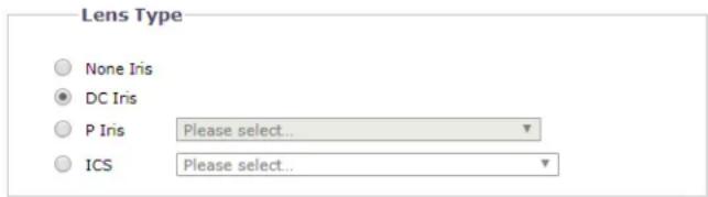
FIGURE 2-29: LENS TYPE
2.2.3.3 Focus
Focus sets the back focus to the center focal point of the scene. The camera can be configured to back focus automatically or manually. Auto focus automatically back focuses the camera on the subject in the center of the scene. Manual focus turns off the auto focus mechanism and locks the camera at a user-specified position. The manual focus setting is recommended only for indoor applications that have a single, unchanging primary light source. The Focus page also includes Full Range
Auto-Focus, Quick Auto-Focus, and a Restore Settings to Defaults.
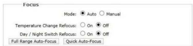

Restore Settings to Defaults
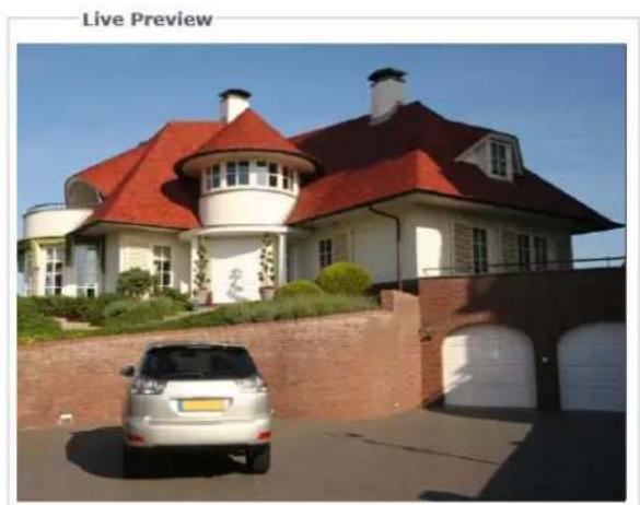
natural_image
Exterior view of a modern residential house with red-tiled roof and white walls, featuring a silver car parked in front (no signage)FIGURE 2-30: FOCUS SETTINGS
Focus
- Auto Focus
-
Temperature Change Refocus: The camera is programmed to run a quick automatic focus sequence when the internal temperature sensor of the camera detects an environmental temperature change of 41^ F ( 5^ C). This focus sequence adjusts the center focal point of the scene to maintain optimal focus. The default setting is Off; select On to turn on this setting.
-
Day/Night Switch Refocus: The default setting for the Day/Night Switch Refocus is Off. Select On if the camera's focal length is greater than 25 mm or the night scene uses mostly IR lighting. The best method to determine if the day/night refocus should be enabled is to test the camera with the daytime light conditions, and then test it again with the nighttime light conditions.
When enabled On this setting refocuses the camera when the camera changes from day mode (color) to night mode (black-white) or vice versa. For example, if the camera changes from day mode to night mode, the imager automatically adjusts the back focus for the change in light.
- If required, use one of the following buttons to adjust the focus:
• Full Range Auto-Focus: The camera starts a full-range search to find the optimal focal point for the scene.
- Quick Auto-Focus: The camera searches for the optimal focal point in a limited range.
- Restore Settings to Defaults: The camera resets the auto focus to the factory default setting.
NOTE: Auto Focus function is available in motorized models only.
- Manual Focus
Select Manual Mode. Two sliders will appear, one for Day Manual Focus Position, the other for Night Manual Focus Position. Each slider will show a value that is the best focus position for the camera during the day and night.
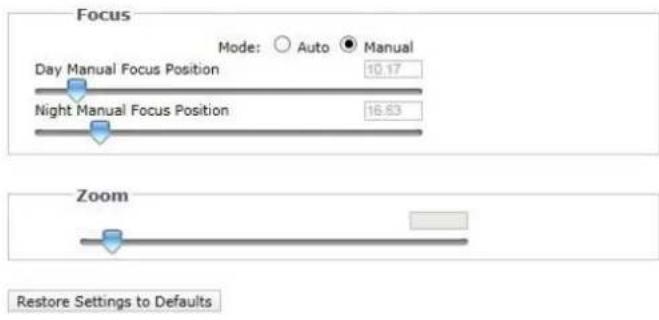
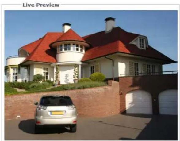
natural_image
Exterior view of a modern house with red-tiled roof and white walls, featuring a silver SUV parked in front (no signage)FIGURE 2-31: MANUAL FOCUS SETTINGS
- Day Manual Focus Position: If you need to fine-tune the daytime focus, slightly move the Day Manual Focus Position slider to the left or right.
- Night Manual Focus Position: If you need to fine-tune the nighttime focus, slightly move the Night Manual Focus Position slider to the left or right.
- If required, click the Restore Settings to Defaults button to reset the focus to the factory default setting.
NOTE: Manual Focus function is available in motorized models only.
Zoom
Manually move the Zoom slider to the left or right to zoom in or zoom out the image, adjust the zoom value from 1.00\~3.00 to get the desired field of view.
NOTE: Zoom function is available in motorized models only.
2.2.3.4 White Balance
Under White Balance, choose from ATW (auto tracing white balance), Auto, and Manual modes of adjustment on white balance for the video. ATW enables automatic controls on color temperature ranging from 2500°K to 10000°K. Auto offers continuous adjustments on camera color balance in accordance with any change in color temperature.

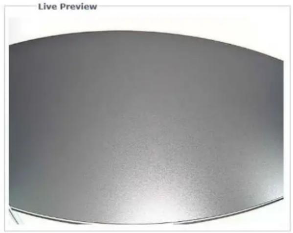
natural_image
Circular metallic object with smooth surface and curved edges, labeled 'Live Preview' at top (no other text or symbols)FIGURE 2-32: WHITE BALANCE SETTINGS
Under Manual mode, the Red and Blue Gain adjustment bars with their scale boxes on their right will appear once the mode is selected. Base color of the video will change as the bars are adjusted left or right. Adjust to the ideal balance as appear fit. Click on One Push to have the camera adjust to the proper gain values rapidly depending on the ambient environment of area viewed, where its light source is constant, without adjusting for any change in light source or color temperature.
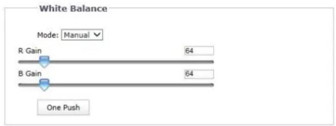
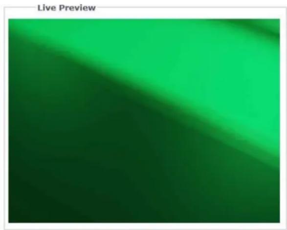
natural_image
Green gradient background with diagonal light streak, no text or symbols visibleFIGURE 2-33: WHITE BALANCE SETTINGS – MANUAL
2.2.3.5 Window Blanking
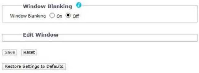
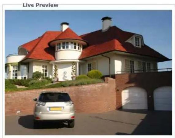
Window blanking is used to conceal user-defined privacy areas. A blanked area appears on the screen as a solid gray window. The camera can handle up to 8 blanked windows as long as the total blanked area does not exceed 50 percent of the field of view.
natural_image
Exterior view of a modern residential house with red-tiled roof and white walls, featuring a silver SUV parked in front (no signage)FIGURE 2-34: WINDOW BLANKING SETTINGS
Window Blanking
- Window Blanking On
- Draw a window in the Live Preview area of the page:
a Hold down the left mouse button.
b Drag the mouse diagonally across the area you want to blank.
c A color-coded box appears in the Edit Window section of the page that is the same color as the window drawn in the Live Preview area.

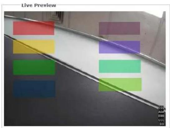
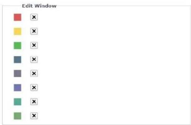
FIGURE 2-35: WINDOW BLANKING ON
NOTE: Up to 8 blanked windows can be defined, but the blanked area cannot exceed 50 percent of the field of view.
- To resize the window, click and drag one or more of the points until the window is the desired shape and size.
- Click the Save button to save the settings, or click the Reset button to clear all of the information you entered without saving it.
- Deleting a window blanking area
- In the Edit Window area of the page, click the Delete button next to the window blanking area you want to delete.
- Click the Save button to save the settings, or click the Reset button to clear all of the information you entered without saving it.
- Window Blanking Off
- Select the Off option for Window Blanking.
- Click the Save button to save the settings, or click the Reset button to clear all of the information you entered without saving it.
2.2.4 A/V Streams
Use the A/V Streams tab to configure the video and audio streams for the camera. The A/V Streams tab includes the Video Configuration page, the Audio Configuration page, the Local Recording page, the RTP Settings page, and the Smart Compression page.
2.2.4.1 Video Configuration
The Video Configuration page allows you to customize the compression, resolution, rate control, image rate, GOP length, Qos codepoint, Endura Signing, and profile of the video streams. The default names for the streams are Primary Stream, Secondary Stream and Tertiary Stream. Although each stream can be configured independently, the settings of one stream can limit the options available to the other stream, depending on the processing power used.
NOTE: Always configure the primary stream before the secondary stream. The primary stream should always be the most resource-intensive of the streams.
Custom Video Stream Configuration
Select Preset
Presets are fully-configured video configurations that offer a good balance of video performance to bandwidth. These presets may also be used as a starting point for a custom configuration.
Corridor mode: Off ▼
High Primary Stream H264, 30 IPS, 2592x1944[4:3], CVBR 7000 kbit/s | Secondary Stream H264, 30 IPS, 800x600[4:3], CVBR 3000 kbit/s | Tertiary Stream H264, 30 IPS, 640x480[4:3], CVBR 3000 kbit/s
Medium Primary Stream H264, 30 IPS, 2048x1536[4:3], CVBR 7000 kbit/s | Secondary Stream H264, 30 IPS, 800x600[4:3], CVBR 3000 kbit/s | Tertiary Stream H264, 30 IPS, 640x480[4:3], CVBR 3000 kbit/s
Low Primary Stream H264, 30 IPS, 1920x1080[16:9], CVBR 7000 kbit/s | Secondary Stream H264, 30 IPS, 640x360[16:9], CVBR 2350 kbit/s | Tertiary Stream H264, 30 IPS, 320x180[16:9], CVBR 2350 kbit/s
Custom
User specified settings for Primary, Secondary and Tertiary Streams
Aspect Ratio: 4:3 ▼ Maximum Frame Rate: 60 fps (No WDR) ▼
Primary Stream
H264, 30, 2592x1944[4:3], cvbr 7000 kbbl/s, High
Clear
Compression Standard: H264
Resolution: 2592x1944[4:3]
Rate Control: CVBR ▼
Image Rate: 30

Maximum Bit Rate (kbit/sec) 7000
QoS (DSCP) Codepoint:
34
Endure Signing:
[Lower framerate possible when Endure Signing ON]
Profile:
High ▼
Secondary Stream
H264, 30, 800x600[4:3], cvbr 3000 kbit/s, High
Clear
Compression Standard: H264
Resolution: 800x600[4:3]
Rate Control: CVBR ▼
Image Rate: 30
GOP Length: (1\~60) 30

Maximum Bit Rate (kbit/sec) 3000

QoS (DSCP) Codepoint:
34
Endure Signing:
(Lower framesite possible when Endure Signing ON)
Profile:
High ▼
Tertiary Stream
H264, 30, 640x480[4:3], cvbr 3000 kbit/s, High
Clear
Compression Standard: H264
Resolution: 640x480[4:3]
Rate Control: CVBR
Image Rate: 30
GOP Length: (1\~60) 30

Maximum Bit Rate (kbit/sec) 3000

QoS (DSCP) Codepoint:
34
Endure Signing:
[Lower framerate possible when Endure Signing ON]
Profile:
High ▼
Save Reset
FIGURE 2-36: CUSTOM VIDEO STREAM CONFIGURATION
Select Preset
Presets are fully-configured video configurations that offer a good balance of video performance to bandwidth. These presets may also be used as a starting point for a custom configuration. Choose to switch the Corridor Mode On or Off. Corridor Mode offers a vertically widened field of view in narrow spaces like hallways and tunnels.
NOTE: Corridor mode is not available when codec is MJPEG.
● High: Typical high bandwidth settings creating high quality images.
● Medium: Typical decent bandwidth settings creating decent quality images.
● Low: Typical low bandwidth settings creating low quality images.
- Custom: User specified settings for Primary, Secondary and Tertiary Streams allowing selection of Aspect Ratio of 3:4 or 16:9, and selection of Maximum Frame Rate of 30 ftp (WDR) or 60 ftp (No WDR).
Primary Stream
Select Custom in Select Preset and configure Primary Stream.
- Compression Standard
- H264: A new version of MPEG-4 compression used in high-definition video players such as Blu-ray ^™ and HD-DVD. H.264 is the most processor-intensive, but it requires the least amount of bandwidth.
- H.265: An improvement of H.264 that provides better compression efficiency while improving image quality and lowering processor workload.
- MJPEG: A commonly used video compression scheme. MJPEG has the least impact on the camera's processor, but it requires the most bandwidth.
- Resolution
Refer to the following table for the resolution capabilities of your camera model.
TABLE 2-2. CORRELATIONS OF RESOLUTIONS/ COMPRESSIONS/ STREAMS
| Resolution | Aspect ratio | FPS | Single stream | Dual stream | Triple stream |
| 5M**** | 4:3 | 30 | 2592x1944 | 2592x1944 + 1600x1200 | 2592x1944 + 1600x1200 + 640x480 |
| 2592x1944 + 1600x1200 + 320x240 | |||||
| 2592x1944 + 1440x1080 | 2592x1944 + 1440x1080 + 640x480 | ||||
| 2592x1944 + 1440x1080 + 320x240 | |||||
| 2592x1944 + 1280x960 | 2592x1944 + 1280x960 + 1280x960 | ||||
| 2592x1944 + 1280x960 + 640x480 | |||||
| 2592x1944 + 1280x960 + 320x240 | |||||
| 2592x1944 + 800x600 | 2592x1944 + 800x600 + 800x600 | ||||
| 2592x1944 + 800x600 + 640x480 | |||||
| 2592x1944 + 800x600 + 320x240 | |||||
| 2592x1944 + 640x480 | 2592x1944 + 640x480 + 640x480 | ||||
| 2592x1944 + 640x480 + 320x240 | |||||
| 2592x1944 + 320x240 | 2592x1944 + 320x240 + 320x240 | ||||
| 3.7M**** | 16:9 | 60/30/30 | 2560x1440 | 2560x1440 + 640x360 | 2560x1440 + 640x360 + 640x360 |
| 2560x1440 + 640x360 + 320x180 | |||||
| 2560x1440 + 320x180 | 2560x1440 + 320x180 + 320x180 | ||||
| 3.7M**** | 16:9 | 30 | 2560x1440 | 2560x1440 + 1920x1080 | 2560x1440 + 1920x1080 + 640x360 |
| 2560x1440 + 1920x1080 + 320x180 | |||||
| 2560x1440 + 1280x720 | 2560x1440 + 1280x720 + 1280x720 | ||||
| 2560x1440 + 1280x720 + 640x360 | |||||
| 2560x1440 + 640x360 | 2560x1440 + 640x360 + 640x360 | ||||
| 2560x1440 + 640x360 + 320x180 | |||||
| 2560x1440 +320x180 | 2560x1440 + 320x180 + 320x180 | ||||
| 3M**** | 4:3 | 60/30/30 | 2048x1536 | 2048x1536 + 1600x1200 | 2048x1536 + 1600x1200 + 640x480 |
| 2048x1536 + 1600x1200 + 320x240 | |||||
| 3M**** | 4:3 | 30 | 2048x1536 | 2048x1536 + 2048x1536 | 2048x1536 + 2048x1536 + 1280x960 |
| 2048x1536 + 2048x1536 + 800x600 | |||||
| 2048x1536 + 2048x1536 + 640x480 | |||||
| 2048x1536 + 2048x1536 + 320x240 | |||||
| 2048x1536 + 1600x1200 | 2048x1536 + 1600x1200 + 1600x1200 | ||||
| 2048x1536 + 1600x1200 + 640x480 | |||||
| 2048x1536 + 1600x1200 + 320x240 | |||||
| 2048x1536 + 1440x1080 | 2048x1536 + 1440x1080 + 640x480 | ||||
| 2048x1536 + 1440x1080 + 320x240 | |||||
| 2048x1536 + 1280x960 | 2048x1536 + 1280x960 + 1280x960 | ||||
| 2048x1536 + 1280x960 + 640x480 | |||||
| 2048x1536 + 1280x960 + 320x240 | |||||
| 2048x1536 + 800x600 | 2048x1536 + 800x600 + 800x600 | ||||
| 2048x1536 + 800x600 + 640x480 | |||||
| 2048x1536 + 800x600 + 320x240 | |||||
| 2048x1536 + 640x480 | 2048x1536 + 640x480 + 640x480 | ||||
| 2048x1536 + 640x480 + 320x240 | |||||
| 2048x1536 + 320x240 | 2048x1536 + 320x240 + 320x240 | ||||
| 3M**** | 16:9 | 60/30/30 | 2304x1296 | 2304x1296 + 1920x1080 | 2304x1296 + 1920x1080 + 640x360 |
| 2304x1296 + 1920x1080 + 320x180 | |||||
| 3M**** | 16:9 | 30 | 2304x1296 | 2304x1296 + 2304x1296 | 2304x1296 + 2304x1296 + 1920x1080 |
| 2304x1296 + 2304x1296 + 1280x720 | |||||
| 2304x1296 + 2304x1296 + 640x360 | |||||
| 2304x1296 + 2304x1296 + 320x180 | |||||
| 2304x1296 + 1920x1080 | 2304x1296 + 1920x1080 + 1920x1080 | ||||
| 2304x1296 + 1920x1080 + 640x360 | |||||
| 2304x1296 + 1920x1080 + 320x180 | |||||
| 2304x1296 + 1280x720 | 2304x1296 + 1280x720 + 1280x720 | ||||
| 2304x1296 + 1280x720 + 640x360 | |||||
| 2304x1296 + 1280x720 + 320x180 | |||||
| 2304x1296 + 640x360 | 2304x1296 + 640x360 + 640x360 | ||||
| 2304x1296 + 640x360 + 320x180 | |||||
| 2304x1296 + 320x180 | 2304x1296 + 320x180 +320x180 | ||||
| 2M**** | 16:9 | 60/60/30 | 1920x1080 | 1920x1080 + 1920x1080 + 640x360 | |
| 2M**** | 16:9 | 60/30/30 | 1920x1080 | 1920x1080 + 1920x1080 | 1920x1080 + 1920x1080 + 1920x1080 |
| 1920x1080 + 1920x1080 + 1280x720 | |||||
| 1920x1080 + 1920x1080 + 640x360 | |||||
| 1920x1080 + 1920x1080 + 320x180 | |||||
| 1920x1080 + 1280x720 | 1920x1080 + 1280x720 + 1280x720 | ||||
| 1920x1080 + 1280x720 + 640x360 | |||||
| 1920x1080 + 1280x720 + 320x180 | |||||
| 1920x1080 + 640x360 | 1920x1080 + 640x360 + 640x360 | ||||
| 1920x1080 + 640x360 + 320x180 | |||||
| 1920x1080 + 320x180 | 1920x1080 + 320x180 + 320x180 | ||||
| 2M**** | 4:3 | 60/30/30 | 1600x1200 | 1600x1200 + 1600x1200 | 1600x1200 + 1600x1200 + 1600x1200 |
| 1600x1200 + 1600x1200 + 1280x960 | |||||
| 1600x1200 + 1600x1200 + 800x600 | |||||
| 1600x1200 + 1600x1200 + 640x480 | |||||
| 1600x1200 + 1440x1080 | 1600x1200 + 1600x1200 + 320x240 | ||||
| 1600x1200 + 1440x1080 + 320x240 | |||||
| 1600x1200 + 1280x960 | 1600x1200 + 1280x960 + 1280x960 | ||||
| 1600x1200 + 1280x960 + 640x480 | |||||
| 1600x1200 + 1280x960 + 320x240 | |||||
| 1600x1200 + 800x600 | 1600x1200 + 800x600 + 800x600 | ||||
| 1600x1200 + 800x600 + 640x480 | |||||
| 1600x1200 + 800x600 + 320x240 | |||||
| 1600x1200 + 640x480 | 1600x1200 + 640x480 + 640x480 | ||||
| 1600x1200 + 640x480 + 320x240 | |||||
| 1600x1200 + 320x240 | 1600x1200 + 320x240 + 320x240 | ||||
| 1.2M**** | 4:3 | 60/30/30 | 1280x960 | 1280x960 + 1280x960 | 1280x960 + 1280x960 + 1280x960 |
| 1280x960 + 1280x960 + 800x600 | |||||
| 1280x960 + 1280x960 + 640x480 | |||||
| 1280x960 + 1280x960 + 320x240 | |||||
| 1280x960 + 800x600 | 1280x960 + 800x600 + 800x600 | ||||
| 1280x960 + 800x600 + 640x480 | |||||
| 1280x960 + 800x600 + 320x240 | |||||
| 1280x960 + 640x480 | 1280x960 + 640x480 + 640x480 | ||||
| 1280x960 + 640x480 + 320x240 | |||||
| 1280x960 + 320x240 | 1280x960 + 320x240 + 320x240 | ||||
| 1M**** | 16:9 | 60/30/30 | 1280x720 | 1280x720 + 1280x720 | 1280x720 + 1280x720 + 1280x720 |
| 1280x720 + 1280x720 + 640x360 | |||||
| 1280x720 + 1280x720 + 320x180 | |||||
| 1280x720 + 640x360 | 1280x720 + 640x360 + 640x360 | ||||
| 1280x720 + 640x360 + 320x180 | |||||
| 1280x720 + 320x180 | 1280x720 + 320x180 + 320x180 | ||||
| 3M*** | 4:3 | 30/15/30 | 2048x1536 | 2048x1536 + 1600x1200 | 2048x1536 + 1600x1200 + 640x480 |
| 2048x1536 + 1600x1200 + 320x240 | |||||
| 3M*** | 4:3 | 30 | 2048x1536 | 2048x1536 + 1280x960 | 2048x1536 + 1280x960 + 640x480 |
| 2048x1536 + 1280x960 + 320x240 | |||||
| 2048x1536 + 800x600 | 2048x1536 + 800x600 + 800x600 | ||||
| 2048x1536 + 800x600 + 640x480 | |||||
| 2048x1536 + 800x600 + 320x240 | |||||
| 2048x1536 + 640x480 | 2048x1536 + 640x480 + 640x480 | ||||
| 2048x1536 + 640x480 + 320x240 | |||||
| 2048x1536 + 320x240 | 2048x1536 + 320x240 + 320x240 | ||||
| 2M*** | 16:9 | 30 | 1920x1080 | 1920x1080 + 1920x1080 | 1920x1080 + 1920x1080 + 640x360 |
| 1920x1080 + 1920x1080 + 320x180 | |||||
| 1920x1080 + 1280x720 | 1920x1080 + 1280x720 + 1280x720 | ||||
| 1920x1080 + 1280x720 + 640x360 | |||||
| 1920x1080 + 1280x720 + 320x180 | |||||
| 1920x1080 + 640x360 | 1920x1080 + 640x360 + 640x360 | ||||
| 1920x1080 + 640x360 + 320x180 | |||||
| 1920x1080 + 320x180 | 1920x1080 + 320x180 + 320x180 | ||||
| 2M*** | 4:3 | 30 | 1600x1200 | 1600x1200 + 1600x1200 | 1600x1200 + 1600x1200 + 640x480 |
| 1600x1200 + 1600x1200 + 320x240 | |||||
| 1600x1200 + 1280x960 + 1280x960 | |||||
| 1600x1200 + 1280x960 + 800x600 | |||||
| 1600x1200 + 1280x960 + 640x480 | |||||
| 1600x1200 + 1280x960 + 320x240 | |||||
| 1600x1200 + 800x600 | 1600x1200 + 800x600 + 800x600 | ||||
| 1600x1200 + 800x600 + 640x480 | |||||
| 1600x1200 + 800x600 + 320x240 | |||||
| 1600x1200 + 640x480 | 1600x1200 + 640x480 + 640x480 | ||||
| 1600x1200 + 640x480 + 320x240 | |||||
| 1600x1200 + 320x240 | 1600x1200 + 320x240 + 320x240 | ||||
| 1.2M*** | 4:3 | 30 | 1280x960 | 1280x960 + 1280x960 | 1280x960 + 1280x960 + 1280x960 |
| 1280x960 + 1280x960 + 800x600 | |||||
| 1280x960 + 1280x960 + 640x480 | |||||
| 1280x960 + 1280x960 + 320x240 | |||||
| 1280x960 + 800x600 | 1280x960 + 800x600 + 800x600 | ||||
| 1280x960 + 800x600 + 640x480 | |||||
| 1280x960 + 800x600 + 320x240 | |||||
| 1280x960 + 640x480 | 1280x960 + 640x480 + 640x480 | ||||
| 1280x960 + 640x480 + 320x240 | |||||
| 1280x960 + 320x240 | 1280x960 + 320x240 + 320x240 | ||||
| 1M*** | 16:9 | 30 | 1280x720 | 1280x720 + 1280x720 | 1280x720 + 1280x720 + 1280x720 |
| 1280x720 + 1280x720 + 640x360 | |||||
| 1280x720 + 1280x720 + 320x180 | |||||
| 1280x720 + 640x360 | 1280x720 + 640x360 + 640x360 | ||||
| 1280x720 + 640x360 + 320x180 | |||||
| 1280x720 + 320x180 | 1280x720 + 320x180 + 320x180 | ||||
| 1M*** | 4:3 | 30 | 800x600 | 800x600 + 800x600 | 800x600 + 800x600 + 800x600 |
| 800x600 + 800x600 + 640x480 | |||||
| 800x600 + 800x600 + 320x240 | |||||
| 800x600 + 640x480 | 800x600 + 640x480 + 640x480 | ||||
| 800x600 + 640x480 + 320x240 | |||||
| 800x600 + 320x240 | 800x600 + 320x240 + 320x240 | ||||
| 1M*** | 4:3 | 30 | 640x480 | 640x480 + 640x480 | 640x480 + 640x480 + 640x480 |
| 640x480 + 640x480 + 320x240 | |||||
| 640x480 + 320x240 | 640x480 + 320x240 + 320x240 | ||||
| 1M*** | 16:9 | 30 | 640x360 | 640x360 + 640x360 | 640x360 + 640x360 + 640x360 |
| 640x360 + 640x360 + 320x180 | |||||
| 640x360 + 320x180 | 640x360 + 320x180 + 320x180 | ||||
| 2M** | 16:9 | 30/15/30 | 1920x1080 | 1920x1080 + 1920x1080 | 1920x1080 + 1920x1080 + 640x360 |
| 1920x1080 + 1920x1080 + 320x180 | |||||
| 2M** | 16:9 | 30 | 1920x1080 | 1920x1080 + 1280x720 | 1920x1080 + 1280x720 + 640x360 |
| 1920x1080 + 1280x720 + 320x180 | |||||
| 1920x1080 + 640x360 | 1920x1080 + 640x360 + 640x360 | ||||
| 1920x1080 + 640x360 + 320x180 | |||||
| 1920x1080 + 320x180 | 1920x1080 + 320x180 + 320x180 | ||||
| 1.2M** | 4:3 | 30 | 1280x960 | 1280x960 + 1280x960 | 1280x960 + 1280x960 + 800x600 |
| 1280x960 + 1280x960 + 640x480 | |||||
| 1280x960 + 1280x960 + 320x240 | |||||
| 1280x960 + 800x600 | 1280x960 + 800x600 + 800x600 | ||||
| 1280x960 + 800x600 + 640x480 | |||||
| 1280x960 + 800x600 + 320x240 | |||||
| 1280x960 + 640x480 | 1280x960 + 640x480 + 640x480 | ||||
| 1280x960 + 640x480 + 320x240 | |||||
| 1280x960 + 320x240 | 1280x960 + 320x240 + 320x240 | ||||
| 1M** | 16:9 | 30 | 1280x720 | 1280x720 + 1280x720 | 1280x720 + 1280x720 + 1280x720 |
| 1280x720 + 1280x720 + 640x360 | |||||
| 1280x720 + 1280x720 + 320x180 | |||||
| 1280x720 + 640x360 | 1280x720 + 640x360 + 640x360 | ||||
| 1280x720 + 640x360 + 320x180 | |||||
| 1280x720 + 320x180 | 1280x720 + 320x180 + 320x180 | ||||
| 1M** | 4:3 | 30 | 800x600 | 800x600 + 800x600 | 800x600 + 800x600 + 800x600 |
| 800x600 + 800x600 + 640x480 | |||||
| 800x600 + 800x600 + 320x240 | |||||
| 800x600 + 640x480 | 800x600 + 640x480 + 640x480 | ||||
| 800x600 + 640x480 + 320x240 | |||||
| 800x600 + 320x240 | 800x600 + 320x240 + 320x240 | ||||
| 1M** | 4:3 | 30 | 640x480 | 640x480 + 640x480 | 640x480 + 640x480 + 640x480 |
| 640x480 + 640x480 + 320x240 | |||||
| 640x480 + 320x240 | 640x480 + 320x240 + 320x240 | ||||
| 1M** | 16:9 | 30 | 640x360 | 640x360 + 640x360 | 640x360 + 640x360 + 640x360 |
| 640x360 + 640x360 + 320x180 | |||||
| 640x360 + 320x180 | 640x360 + 320x180 + 320x180 | ||||
| 1M** | 4:3 | 30 | 320x240 | 320x240 + 320x240 | 320x240 + 320x240 + 320x240 |
| 1M** | 16 : 9 | 30 | 320x180 | 320x180 + 320x180 | 320x180 + 320x180 + 320x180 |
| 1.2M* | 4:3 | 30 | 1280x960 | 1280x960 + 1280x960 | 1280x960 + 1280x960 + 800x600 |
| 1280x960 + 1280x960 + 640x480 | |||||
| 1280x960 + 1280x960 + 320x240 | |||||
| 1280x960 + 800x600 | 1280x960 + 800x600 + 800x600 | ||||
| 1280x960 + 800x600 + 640x480 | |||||
| 1280x960 + 800x600 + 320x240 | |||||
| 1280x960 + 640x480 | 1280x960 + 640x480 + 640x480 | ||||
| 1280x960 + 640x480 + 320x240 | |||||
| 1280x960 + 320x240 | 1280x960 + 320x240 + 320x240 | ||||
| 1M* | 16:9 | 30 | 1280x720 | 1280x720 + 1280x720 | 1280x720 + 1280x720 + 1280x720 |
| 1280x720 + 1280x720 + 640x360 | |||||
| 1280x720 + 1280x720 + 320x180 | |||||
| 1280x720 + 640x360 | 1280x720 + 640x360 + 640x360 | ||||
| 1280x720 + 640x360 + 320x180 | |||||
| 1280x720 + 320x180 | 1280x720 + 320x180 + 320x180 | ||||
| 1M* | 4:3 | 30 | 800x600 | 800x600 + 800x600 | 800x600 + 800x600 + 800x600 |
| 800x600 + 800x600 + 640x480 | |||||
| 800x600 + 800x600 + 320x240 | |||||
| 800x600 + 640x480 | 800x600 + 640x480 + 640x480 | ||||
| 800x600 + 640x480 + 320x240 | |||||
| 800x600 + 320x240 | 800x600 + 320x240 + 320x240 | ||||
| 1M* | 4:3 | 30 | 640x480 | 640x480 + 640x480 | 640x480 + 640x480 + 640x480 |
| 640x480 + 640x480 + 320x240 | |||||
| 640x480 + 320x240 | 640x480 + 320x240 + 320x240 | ||||
| 1M* | 16:9 | 30 | 640x360 | 640x360 + 640x360 | 640x360 + 640x360 + 640x360 |
| 640x360 + 640x360 + 320x180 | |||||
| 640x360 + 320x180 | 640x360 + 320x180 + 320x180 | ||||
| 1M* | 4:3 | 30 | 320x240 | 320x240 + 320x240 | 320x240 + 320x240 + 320x240 |
| 1M* | 16 : 9 | 30 | 320x180 | 320x180 + 320x180 | 320x180 + 320x180 + 320x180 |
* NOTE: Supports 1MP Model only.
** NOTE: Supports 2MP Model only.
*** NOTE: Supports 3MP Model only.
**** NOTE: Supports 5MP Model only.
- Rate Control
The rate control setting determines the bit rate and quality of each frame in the video stream.
- CBR: The constant bit rate (CBR) streams video at a fixed number of bits per second. CBR uses the full capacity of the bit rate setting for scenes with or without motion. Video is always streamed at the user bit rate setting. Adjust the CBR Bit Rate slider that appears when CBR is selected to the optimal fixed number of bits per second.
- CVBR: The constrained variable bit rate (CVBR) provides high-quality video and long recording time of variable bit rate while limiting variations in recording capacity consumption. Adjust the Maximum Bit Rate slider that appears when CVBR is selected to the optimal bit rate for your configuration.
- Image Rate
The image rate is the number of images per second (ips) available for the video stream configuration. Available image rates are 30, 25, 20, 16.67, 15, 12.5, 12, 10, 7.5, 5, 3, 2, and 1.
NOTE: The maximum image rate setting might not be obtainable due to the programmed compression standard and the resolution of the stream.
- GOP Length
Select the GOP Length from 1 to 60. The upper limit depends on the selected image rate. Recovery of the lost frames will be more difficult as the value gets bigger. Smaller values will increase the bit rate and network bandwidth demands. This setting is only available with H264 and H265.
- QoS (DSCP) Codepoint
Quality of Service (QoS) for Differentiated Services Code Point (DSCP) is a code that allows the network to prioritize the transmission of different types of data. This setting is only available with H264 and H265.
NOTES:
- If you are not familiar with DSCP, contact your network administrator before changing this setting.
- Your network must be configured to use QoS. If you are unsure if your network is QoS-aware, contact your network administrator.
- Endura Signing
Enabling the Endura Signing feature allows an Endura® system to authenticate video from an Endura recorded stream. This setting is only available with H264 and H265.
- Profile
The profile defines the subset of bit stream features in an H.264 and H265 streams, including color reproduction and additional video compression. It is important that the selected profile is compatible with the recording device so that a stream can be decoded and viewed.
- High: A complex profile with a high compression ratio. This is the primary profile for high-definition television applications; for example this is the profile adopted for Blu-ray and HD-DVD. The high profile supports I-frames, P-frames, and B-frames.
- Main: An intermediate profile with a medium compression ratio. Main is the default profile setting. This profile is compatible with most recorders and uses fewer bits to compress video than the baseline profile; however, it uses more bits than the high profile. The main profile supports I-frames, P-frames, and B-frames.
- Baseline: A fairly basic profile that is almost compatible with an array of applications.
Secondary Stream
Select Custom in Select Preset and configure Secondary Stream. Repeat Primary Stream setting steps for the Secondary Stream settings.
Tertiary Stream
Select Custom in Select Preset and configure Tertiary Stream. Repeat Primary Stream setting steps for the Tertiary Stream settings.
2.2.4.2 Audio Configuration
The Audio Configuration page allows you to setup the audio device. The default setting for Audio is disabled, which means that no audio is transmitted from the camera. When enabled, audio is transmitted from the camera to the PC. Based on your system configuration, images and audio may not be synchronized.
NOTE: Improper use of audio/visual recording equipment may subject you to civil and criminal penalties. Applicable laws regarding the use of such capabilities vary between jurisdictions and may require, among other things, express written consent from the recorded subjects. You are solely responsible for insuring strict compliance with such laws and for strict adherence to any/all rights of privacy and personality.
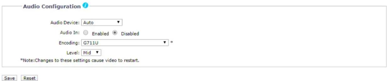
FIGURE 2-37: AUDIO CONFIGURATION
Audio Device
Select which audio source will be in use from the following three options.
● Auto: Selecting Auto allows the device to automatically detect available audio source, prioritizing Line In.
- Microphone In: Sound is received via audio built-in microphone in source capable of processing both analog and digital data.
● Line In: Sound is received via audio line in source.
NOTE: Audio Device feature for selecting audio source is only supported by indoor dome models. All other models only audio source is Line In.
Audio In
- Enabled
Set to Enabled when receiving audio from a microphone plugged into the unit.
- Disabled
Set to Disabled to close Audio In.
Encoding
Two audio codecs G711-Alaw/G711-Ulaw can be chosen from.
Level
The selectable sound levels are High, Mid, and Low.
NOTE: Changes to these settings cause video to restart.
2.2.4.3 Local Recording
Local Recording enables users to record and save video files locally on the SD card inserted, instead of recording and saving them over the network that will occupy a huge portion of memory and bandwidth. Check to enable this type of recording. Note that once the card is full, the oldest and previously-recorded video files on the card will be overwritten when the option "Enable Continuous Recording" is checked.

Here a user can configure multicast RTP streams. RTP is a common way of transmitting and synchronizing surveillance system video and audio streams over RTSP session. Multicast provides the most efficient usage of bandwidth when there are large numbers of clients viewing simultaneously.
![Multicast Primary Video Stream Address: 239.168.11.105 Port: 4554 [0, 1024..65534; even values] Time to Live (TTL): 10 [1..255] □ Always Multicast this stream Audio Stream Address: 239.168.11.105 Port: 2986 [0, 1024..65534; even values] Time to Live (TTL): 10 [1..255] □ Always Multicast this stream Secondary Video Stream Address: 239.168.11.105 Port: 2946 [0, 1024..65534; even values] Time to Live (TTL): 10 [1..255] □ Always Multicast this stream Tertiary Video Stream Address: 239.168.11.105 Port: 5758 [0, 1024..65534; even values] Time to Live (TTL): 10 [1..255] □ Always Multicast this stream Restore Default Multicast Settings Revert to previous Multicast Settings Save TCP/IP Max. Transfer Unit (MTU): 1450 [576..1500] Restore Default TCP/IP Settings Revert to previous TCP/IP Settings Save](/content/2026/05/1055483/images/19bb4e8d8641beba15c47fe71f8a803c8d8fc1b199cda4702ff1ab1395a2b303.jpg)
FIGURE 2-39: RTP SETTINGS
Primary Video Stream
- Address: Set the multicast address for RTP video streaming.
-
Port: Set the multicast port number for RTP video streaming to an even number in the range 1024 to 65534. To disable the port set value to 0.
-
Time to Live (TTL): Set the effective scope of multicast distribution for RTP video streaming between 1 and 255. TTL is a mechanism that limits the lifespan of data in a computer or network. It is implemented by having a counter or timestamp attached or embedded in the data in order to ensure that data is discarded once the correct time is reached. TTL counter decrements each time the signal pass through a router, so when the value reaches 0, the signal can no longer be distributed. For example, if TTL is set to [1], multicast distribution is confined to the local segment only and cannot be distributed by the router.
- Always Multicast this stream: Check this box to start on-demand multicast RTP video stream without opening a new RTSP session.
Secondary Video Stream
Repeat Primary Video Stream setting steps for the Secondary Stream settings.
Tertiary Video Stream
Repeat Primary Video Stream setting steps for the Tertiary Stream settings.
Audio Stream
Repeat Primary/Secondary Video Stream setting steps for the Audio Stream settings. However, notice that settings here are related to Audio, not video. NOTE: Audio stream configuration is synchronized to each video stream.
Restore Default Multicast Settings: Click this button to restore to the camera's default multicast settings.
Revert to previous Multicast Settings: Click this button to revert to the camera's previous multicast settings.
TCP/IP
Max. Transfer Unit (MTU): Set the value in the range 576 to 1500 for the largest packet size that can be sent through RTP streaming.
Restore Default TCP/IP Settings: Click this button to restore to the camera's default TCP/IP settings.
Revert to previous TCP/IP Settings: Click this button to revert to the camera's previous TCP/IP settings.
2.2.4.5 Pelco Smart Compression
The Pelco Smart Compression features the brilliantly efficient stream compression technology to not only economically exert leverage between different regions and compression levels, but also effectively reduce the average bit rate to level down the overall bandwidth exploitation. Refer to the following section for elaborate descriptions.
Pelco Smart Compression
Smart Compression Level
Off
No bitrate reduction.
Low
No visible effect in most scenes.
Medium
Effects visible in some scenes.
High
Effects visible in many scenes.
Advanced Settings

Enable Dynamic GOP Length
Save Reset
FIGURE 2-40: H.264 PELCO SMART COMPRESSION
Smart Compression Level
Smart Compression swiftly identifies dynamic motions occurred within a scene and retains its details with clear quality, whereas the rest areas, e.g. static background, will be imposed on higher compression level, thus economically decreasing bandwidth wielding on less important things and still keeping the dynamic motions details for future forensic purpose. The intensity for Smart Compression can be defined by the different levels options. Select Off will simply disable this function.
Advanced Settings
Enable Dynamic GOP Length: Smart Compression allows user to enable Dynamic GOP Length, which results in a significant bit rate reduction while keeping essentially the same video quality. Dynamic GOP achieves this feat by dynamically adjusting the interval between I-frames according to amount of motion in the scene. Hence, when in a scene there is limited or no motion; fewer I-frames will be used.
2.2.5 Event Source
Use the Events tab to configure camera events detections and the following handlers. Events detections are activated by user-defined event sources that tell the device how to react when a specific event occurs. Event handlers are the actions that the device takes when an event occurs. For example, an event source can be configured to alarm an operator via sending email notification if a motion occurs within the predefined camera's coverage.
2.2.5.1 Alarm Source
This page allows user to configure the settings of the connected alarm input source, which is the external alarm signaling device, such as a door contact or motion detector. Both normally open and normally closed devices are supported.

FIGURE 2-41: ALARM SOURCE
Alarm Input Settings
- Check Enabled button to enable Alarm Input.
- Select either Normally Open or Normally Closed from the Polarity drop-down menu.
• Normally Open: An alarm will be triggered when the external contact closes.
• Normally Closed: An alarm will be triggered when the external contact opens.
Click the Save button to save the settings, or click the Reset button to clear all of the information you entered without saving it.
NOTE: The Alarm Source function is available in Alarm equipped models only.
2.2.5.2 Motion Detection
This page is designed to define multiple groups of motion detection zones with specific own thresholds for triggering.
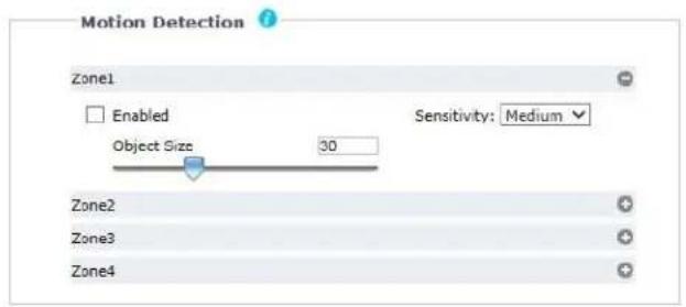
Save Reset
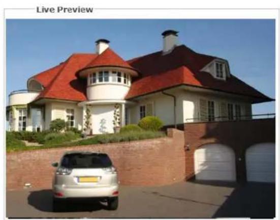
natural_image
Exterior view of a modern house with red-tiled roof and white walls, featuring a silver car parked in front (no signage)FIGURE 2-42: MOTION ZONE AREA SETTING
Motion Zone Area Setting
- Check Enabled button to enable Motion for any or all of Zones 1 to 4.
NOTE: Click on the button "→" to expand section of each zone setting, and click the button "→" to collapse each section.
- Sensitivity: Choose different levels of sensitivity from High, Medium, and Low.
• High: Motion is activated with slight changes in brightness or motion.
- Low: Motion is activated with big changes in brightness or motion.
• Medium: The threshold of sensitivity is in the middle between High and Low.
-
Object Size can be defined from the range 1 to 100 for detection on wanted objects.
-
Set the desired area to trigger motion detection. The red frame of motion setup will appear for defining the detection area by dragging the mouse. The zone can be resized and repositioned by selecting it in the Live Preview window
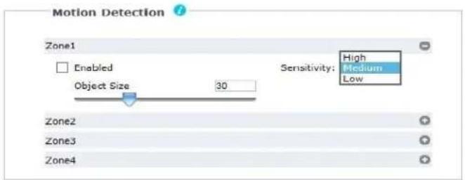
Save Reset
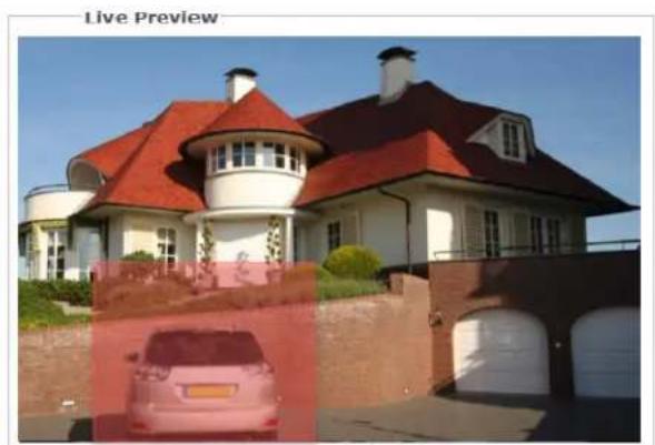
natural_image
Exterior view of a modern house with red-tiled roof and adjacent storage tanks (no signage)FIGURE 2-43: MOTION ZONE AREA ENABLING
- Click the Save button to save the settings, or click the Reset button to clear all of the information you entered without saving it.
2.2.5.3 Sabotage Detection
The Camera Sabotage behavior detects scene changes or contrast changes in the field of view. An event or alarm is triggered if the lens is obstructed by spray paint, a cloth, or if it is covered with a lens cap. Any unauthorized repositioning of the camera also triggers an event or alarm.
Scene Setup for Camera Sabotage
Install the camera in a high position, looking down on the scene. The field of view should be as large as possible. A small field of view could result in the view being blocked by an adjacent object.
Avoid scenes with a dark, uniform background, low lighting, and large moving objects.
Sabotage Detection
- Check Enabled button to enable Sabotage Detection.
-
Configure the settings:
-
Sensitivity: Determines the triggering sensitivity for alarm. High sensitivity is triggered most easily but is prone to more false alarms. Low sensitivity will only trigger an alarm for major issues like blackout.
- Event logging (Profile) name: Type a user-defined string name that will display within an alarm event to help users to easily distinguish among cameras.
• Alarm Severity: Defines the severity of an alarm to allow the prioritization of alarms.

FIGURE 2-44: SABOTAGE DETECTION
- Click the Save button to save the settings, or click the Reset button to clear all of the information you entered without saving it.
2.2.5.4 Audio Detection
This function is designed to define the audio intensity threshold for triggering an alarm from surrounding audio. Check to enable this function. With an external mic connected, a waveform representing the level of audio intensity will be displayed in the box.
Under Sound Intensity Threshold, adjust the threshold bar or input a number (from 0 to 100) in the box right above it for the desired threshold level. A horizontal line, which indicates the exact threshold, in the box underneath will move up or down accordingly.
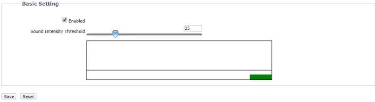
FIGURE 2-45: AUDIO DETECTION
2.2.5.5 Object Counting
The Object Counting behavior counts the number of objects that enter a user-defined zone. This behavior can be used to count people at a store entrance/exit or inside a store where the traffic is light. It might also be used to monitor vehicle traffic on highways, local streets and roads, parking lots, and garages.
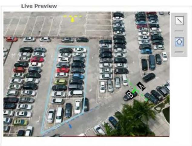
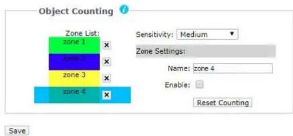
FIGURE 2-46: OBJECT COUNTING SETTING
Object Counting
- Select "☑", then click and hold on the left-side preview image to draw a line on the wanted area (up to three lines can be drawn).
- Select "☐", then click on the left-side preview image to draw a desired shape (three to eight sides) covering the desired area.
- Click " " to delete a specific Zone
-
Select a specific Zone from the Zone list to perform the following actions..;
-
Type a desired name for each Zone.
- The options from Direction dropdown menu (A to B, B to A) helps user to define the exact direction to be counted.
- Check Enable button to enable Object Counting for any or all of the Zones.
-
Pressing the Reset Counting button will erase the accumulated counting records.
-
Sensitivity: Choose different levels of sensitivity from High, Medium High, Medium, Medium Low and Low.
When High is selected Object Counting is activated with slight changes in brightness or motion. On the contrary, when Low is selected Object Counting is activated with big changes in brightness or motion.
-
Click the Save button to save the settings.
-
Switch to the Live View page and select Object Counting from the Video Analytics dropdown menu. When there is a moving object traveling through the designated line, the number coming along with the arrow and line will increase ("1" shown in the image). Also, when there is a moving object entering into or moving off the designated area, the OSD counter will show the digit that represents the accumulated number of objects entering and leaving the designated area. Furthermore, any moving object within the live view will be framed by a blue rectangle for clear identification.
2.2.5.6 Adaptive Motion
The Adaptive Motion behavior detects and tracks objects that enter a scene and then triggers an alarm when the objects enter a user-defined zone. The Adaptive Motion behavior is designed to work indoors and outdoors to track a few moving objects in uncrowded fields of view. The behavior learns the background scene over time and adjusts to changing conditions like snow, fog, wind, and rain.
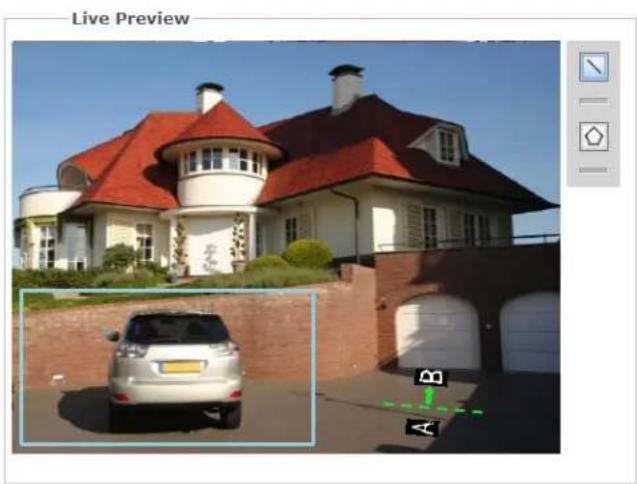
natural_image
Exterior view of a modern house with red-tiled roof and white walls, showing a parked car in front (no signage or text)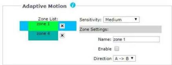
Save
FIGURE 2-47: ADAPTIVE MOTION SETTING
Adaptive Motion
- Select “☑”, then click and hold on the left-side preview image to draw a line on the wanted area (up to three lines can be drawn).
- Select "☐", then click on the left-side preview image to draw a desired shape (three to eight sides) covering the desired area.
- Click " " to delete a specific Zone
-
Select a specific Zone from the Zone list to perform the following actions;
-
Type a desired name for each Zone.
- The options from Direction dropdown menu (A to B, B to A) helps user to define the exact direction to be counted.
-
Check Enable button to enable Adaptive Motion for any or all of the Zones.
-
Sensitivity: Choose different levels of sensitivity from High, Medium High, Medium, Medium Low and Low. When High is selected Adaptive Motion is activated with slight changes in brightness or motion. On the contrary,
when Low is selected Adaptive Motion is activated with big changes in brightness or motion.
-
Click the Save button to save the settings.
-
Switch to the Live View page and select Adaptive Motion from the Video Analytics dropdown menu. When there is a moving object crossing the designated line as the above image, both the crossed borderline and the rectangular frame enclosing the moving object are highlighted with red color for distinctive identification. Also, when there is a moving object trespassing into the designated critical zone defined by administrator, both the rectangular frame enclosing the suspect object and the defined zone are highlighted with red color for distinctive identification. Furthermore, any moving object within the live view will be framed by a blue rectangle for clear identification.
2.2.5.7 Object Removal
The Object Removal analytic behavior triggers an alarm if an object is removed from a user-defined zone. It is ideal for detecting the removal of high-value objects, such as a painting from a wall or a statue from a pedestal.
natural_image
Interior view of an art gallery with visitors viewing framed artworks on walls (no visible text or signage)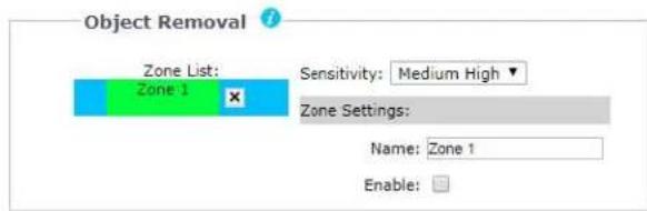
Save
FIGURE 2-48: OBJECT REMOVAL SETTING
Object Removal
- Select "☐", then click and hold on the left-side preview image to draw a box (up to two can be drawn) covering the desired area. The zone(s) can be resized and repositioned by selecting it in the Live Preview window.
- Click " " to delete a specific Zone.
-
Select a specific Zone from the Zone list to perform the following actions;
-
Type a desired name for each Zone.
-
Check Enable button to enable Object Removal for any or all of the Zones.
-
Sensitivity: Choose different levels of sensitivity from High, Medium High, Medium, Medium Low and Low. When High is selected Object Removal is activated with slight changes in brightness or motion. On the contrary, when Low is selected Object Removal is activated with big changes in brightness or motion.
-
Click the Save button to save the settings
- Switch to the Live View page and select Object Removal from the from the Video Analytics dropdown menu. When any of the items marked by colorful zones is taken away, the zone will be highlighted with red color to indicate the original item was taken away. Besides, any moving object within the live view will be framed by a blue rectangle for clear identification.
2.2.6.8 Directional Motion
The Directional Motion behavior generates an alarm in a high traffic area when a person or object moves in a specified direction. Examples of typical installations for this behavior include airports, entrances and exits, and vehicle traffic through tunnels. In an airport installation, cameras observe passengers boarding a plane in a terminal. If a person moves in the opposite direction of the normal flow of traffic, an alarm triggers. In a tunnel installation, an operator wants to observe traffic flow. If a car enters a tunnel through an exit, an alarm alerts the operator to activate the traffic signals to stop all traffic in the tunnel. In an entrance or exit installation, a camera is pointed at an exit door. If a person tries to enter through the exit door, an alarm triggers.

natural_image
Highway traffic scene with multiple vehicles and a green bounding box overlay (no visible text or symbols)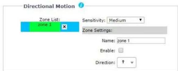
Save
FIGURE 2-49: DIRECTIONAL MOTION SETTING
Directional Motion
- Select "☐", then click and hold on the left-side preview image to draw a box (up to two zones can be drawn) covering the desired area. The zone(s) can be resized and repositioned by selecting it in the Live Preview window.
- Click " " to delete a specific Zone.
-
Select a specific Zone from the Zone list to perform the following actions;
-
Type a desired name for each Zone.
- The options from Direction dropdown menu (arrows) helps user to define the exact direction allowed for movement.
-
Check Enable button to enable Directional Motion for any or all of the Zones.
-
Sensitivity: Choose different levels of sensitivity from High, Medium High, Medium, Medium Low and Low. When High is selected Directional Motion is activated with slight changes in brightness or motion. On the contrary, when Low is selected Directional Motion is activated with big changes in brightness or motion.
-
Click the Save button to save the settings
- Switch to the Live View page and select Directional Motion from the Video Analytics dropdown menu. When there's a moving vehicle crossing the polygon area but toward a direction away from the permitted range, i.e., arrow in Direction dropdown menu, the rectangular frame enclosing the detected vehicle is highlighted by red color for distinctive identification. Besides, any moving object within the live view will be framed by a blue rectangle for clear identification.
2.2.6 Event Handler
2.2.6.1 FTP Upload Handler
Under this page, the camera can record and send snapshot files via properly predefined FTP settings for different events composed of Alarm, Zone, Sabotage, Schedule, Audio Detection, Object Counting, Adaptive Motion, Object Removal, as well as Directional Motion.
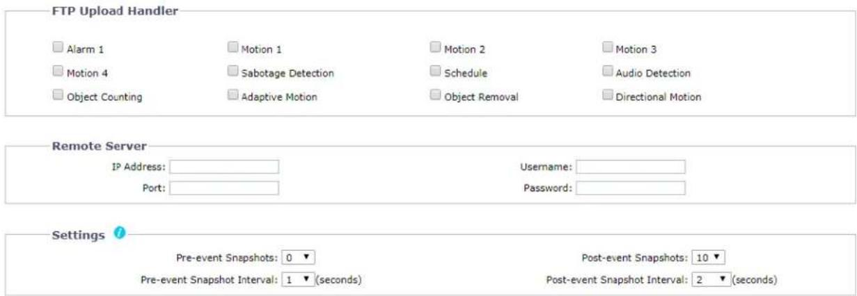
FIGURE 2-50: FTP UPLOAD HANDLER
FTP Upload Handler
You can record and send event image files based on the condition you have set previously.
- Check to enable FTP Upload Handler for Alarm, Motions 1 through 4, Sabotage Detection, Schedule, Audio Detection, Object Counting, Adaptive Motion, Object Removal, as well as Directional Motion.
- Click the Save button to save the settings, or click the Reset button to clear all of the information you entered without saving it.
Remote Server
Remote Server is used as a service component to transfer files by simply entering the IP address or hostname with the Login ID and password.
- IP Address: Input a server name or address.
- Port: Set "21" as default or change to dedicated number.
- Username: Input a user name with privilege to access the server.
- Password: Input the password associated with Username.
NOTE: The default Username and Password are "guest" and "1234".
Settings
- Set Pre-event Snapshots, Post-event Snapshots, Pre-event Snapshot Interval, and Post-event Snapshot Interval for Alarm, Motions 1 through 4, Sabotage Detection, Schedule, and Audio Detection selected.
- Click the Save button to save the settings, or click the Reset button to clear all of the information you entered without saving it.
Snapshot Naming
By setting File Name Prefix and Server Path for Alarm, Motions 1 through 4, Sabotage Detection, Schedule, Audio Detection, Object Counting, Adaptive Motion, Object Removal, as well as Directional Motion selected, you will be able to save an image to a defined FTP server when any of your selected events is activated. Set the Server Path where the data is to be stored on the server.
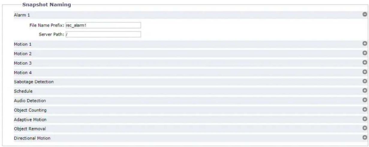
Save Reset
FIGURE 2-51: SNAPSHOT NAMING
You can also set Trigger Interval time and determine the recording condition: OFF, All Day, Schedule 1, or Schedule 2 from scheduled table during 24/7 for Schedule. The trigger interval can be adjusted on a scale bar with its corresponding seconds shown in the box underneath.
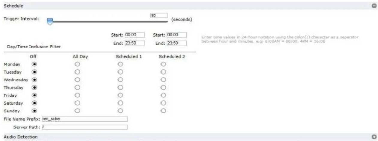
FIGURE 2-52: FTP UPLOAD HANDLER SCHEDULED SETTINGS
2.2.6.2 Relay Open/Close Handler
Define the relay related settings for alarm output device when a selected event is triggered under this page. The connected relay external device can be activated by the method of Normally Open or Normally Closed.
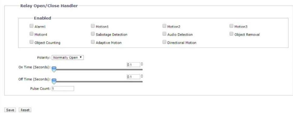
FIGURE 2-53: RELAY OPEN/CLOSE HANDLER SETTINGS
Relay Open/Close Handler
- Check any or all of the Alarm, Motion 1 through 4, Sabotage Detection, Audio Detection, Object Counting, Adaptive Motion, Object Removal, as well as Directional Motion options from the Enabled section to activate relay handler when any of the selected events occur.
- Select Normally Open or Normally Close from the drop-down menu of Polarity for the relay handler.
- Move the On Time slider to set the amount of time that the relay will remain open. The time range is 0.1 to 200 seconds; the default setting is 0.1.
- Move the Off Time slider to set the amount of time that the relay will remain closed. The time range is 0.1 to 200 seconds; the default setting is 0.1.
- Click the Save button to save the settings, or click the Reset button to clear all of the information you entered without saving it.
NOTE: The Relay Open/Close Handler is available in Alarm equipped models only.
2.2.6.3 SD Record Handler
Save video clip backups from a variety of activated events to an SD card. Before using this function, a SD card must be installed in the camera beforehand.
NOTE: The SD card must be formatted as FAT32. Other formats are not compatible with the camera.
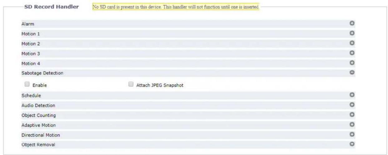


Save Reset
FIGURE 2-54: SD RECORD HANDLER SETTINGS
- Check to enable SD Record Handler for Alarm, Motions 1 through 4, Sabotage Detection, Schedule, Audio Detection, Object Detection, Adaptive Motion, Directional Motion, and Object Removal.
- Select the Attach JPEG Snapshot box if you want to send a JPEG as an attachment.
- Choose either Video only or Audio and Video for Record Type, and choose One Shot or Continuous for Record Status. Then, set a Clip Duration (5\~10 seconds) and Clip Size (10\~20 MB).
NOTE: It is required to define duration and size parameters for "One Shot" method, whilst only size value needs to be defined for "Continuous" method. - Set overwrite ON or Off to enable or disable the SD card to be overwritten automatically when the SD card is full of recordings.
- Usage: Information of SD card usage.
- SD Format: Click to erase information off from the SD card.
- Click the Save button to save the settings, or click the Reset button to clear all of the information you entered without
saving it.
Viewing SD Card Files from a Remote Server
- Configure the SD Record Handler for Alarm, Motions 1 through 4, Sabotage Detection, Schedule, Audio Detection, Object Detection, Adaptive Motion, Directional Motion, and Object Removal.
- Type "ftp://" followed by the IP address of the camera in a Web browser or Windows Explorer.
- Right-click on a snapshot or recording from the SD card and save the file locally or open the file to view its content.
Format SD card as FAT32
- Double click guiformat.exe, the FAT32 Format window will pop up as the figure shows below.
- Select the hard disk/SD card you want to format as FAT32 from the Drive drop-down menus, and then click Start button to begin format the hard disk/SD card.
NOTE: Format will erase all information off of the hard disk/SD card. Make sure you have any important files backed up before you format it.
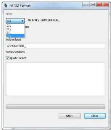
FIGURE 2-55: FAT32 FORMAT
- When the progress bar is full, click Close to complete format and exit the format window.
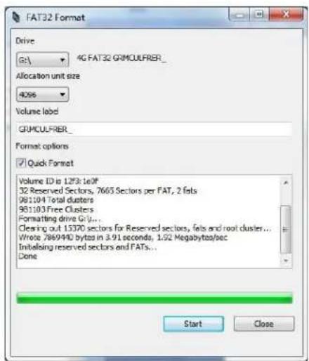
FIGURE 2-56: FAT32 FORMAT COMPLETE
2.2.6.3 SMTP Notification Handler
Set detailed SMTP Notification Handler function that will send an email to predefined email addresses when any or all the selected events are activated.
NOTE: To use email notification, the camera must be connected to a local area network (LAN) that maintains an SMTP mail server. Consult your network administrator for information on configuring email notification on your local network.
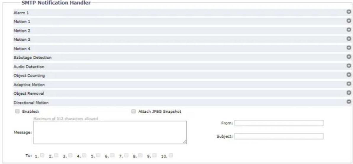

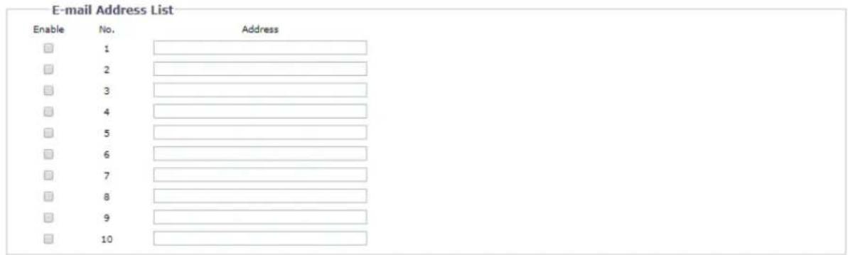
Save Reset
FIGURE 2-57: SMTP NOTIFICATION HANDLER SETTINGS
SMTP Notification Handler
- Check the Enabled button to enable SMTP Notification Handler for Alarm, Motions 1 through 4, Sabotage Detection, Audio Detection, Object Detection, Adaptive Motion, Directional Motion, and Object Removal.
- Click in the text boxes (Message, From, and Subject), and then type the necessary information in each text box.
- Select the Attach JPEG Snapshot box if you want to send a JPEG as an attachment.
- Continue to set the SMTP Server and Address List.
SMTP Server
Set up Simple Mail Transfer Protocol (SMTP), the Internet standard for electronic mail (e-mail) service across Internet Networking, related settings under this section.
- Host Address: Input a server name or address.
- Port: set "25" as default or change to dedicated number.
- Username: Input a user name with privilege to access the server.
- Password: Input the password associated with Login ID.
-
Authentication: Select an authentication type.
-
NO_AUTH: Namely No Authentication, means no restriction.
- SMTP_PLAIN: PLAIN is the name of a registered SASL authentication mechanism which serves as a parameter to the AUTH command. The PLAIN authentication mechanism is described in RFC 2595. PLAIN is the least secure of all the SASL authentication mechanisms since the password is sent unencrypted across the network.
- LOGIN: The LOGIN mechanism is supported by Microsoft's Outlook Express as well as by some other clients.
-
TLS_TTLS: TLS is usually implemented on top of any of the Transport Layer protocols encapsulating the application-specific protocols such as HTTP, FTP, SMTP, NNTP and XMPP. The TLS protocol allows client-server applications to communicate across a network in a way designed to prevent eavesdropping and tampering. TLS can also be used to tunnel an entire network stack to create a VPN as is the case with OpenVPN.
-
Continue set the E-mail Address List.
E-mail Address List
This section is designed to notify multiple users via email when the handler condition is set.
- Check Enable and input the E-mail Address accordingly.
- Click the Save button to save the settings, or click the Reset button to clear all of the information you entered without saving it.
2.2.6.4 Sound Notification Handler
This page is designed for configuring detailed settings for sound notifications when an event occurs.
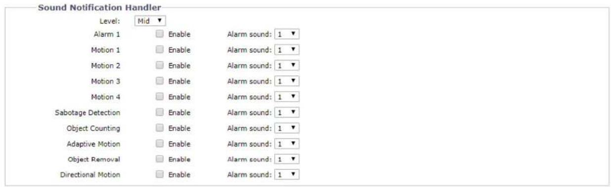
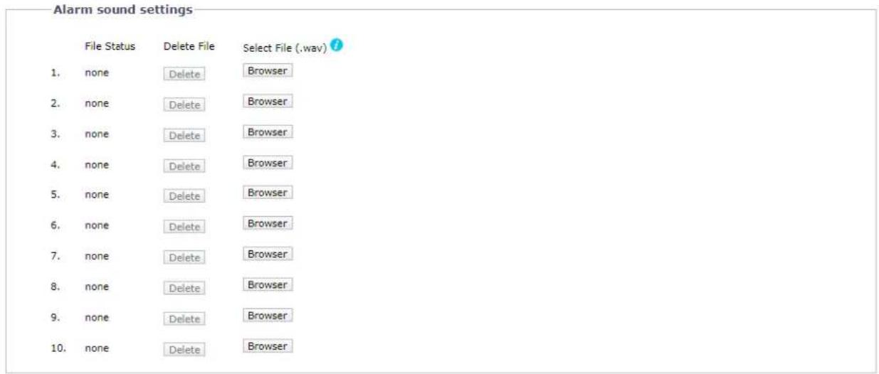
Save Reset
FIGURE 2-58: SOUND NOTIFICATION HANDLER SETTINGS
Sound Notification Handler
- Select the level ranging from High, Mid to Low for sound notification handlers of different events.
- Check to enable any or all of Alarm, Motions 1 through 4, Sabotage Detection, Object Detection, Adaptive Motion, Directional Motion, and Object Removal; and select one of the ten alarm sounds from the dropdown menu that is designated for the different events enabled.
- Continue to set the Alarm Sound Settings.
Alarm Sound Settings
- Customize up to 10 sound files for each event alarm. Click on Browser and locate a desired sound file, which should be specific 8kHz 16bit .wav format, from your computer to upload to the camera. The number will correspond to that under Alarm sound to be selected for the Alarm, Motion 1 through 4, Sabotage Detection, Object Detection, Adaptive Motion, Directional Motion, or Object Removal you enabled.
- In the vicinity of each number from the list, the status of the uploaded sound will be displayed under File Status
(with "none" displayed when no file is uploaded) and the Delete button will be enabled. Click on Delete to delete the file if necessary.
- Click the Save button to save the settings, or click the Reset button to clear all of the information you entered without saving it.
2.2.6.5 OSD Handler
OSD Handler allows user to enable "On Screen Display" settings, which triggers text to be displayed in live view when any or all the selected events are selected.
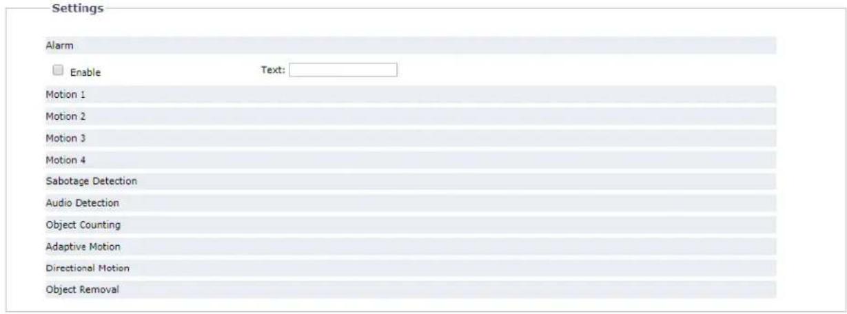
Save
Reset
FIGURE 2-59: SOUND NOTIFICATION HANDLER SETTINGS
Settings
- Check to enable OSD Handler for Alarm, Motions 1 through 4, Sabotage Detection, Audio Detection, Object Detection, Adaptive Motion, Directional Motion, and Object Removal.
- Type a text message to be displayed.
Pelco Troubleshooting Contact Information
If the instructions provided fail to solve your problem, contact Pelco Product Support at 1-800-289-9100 (USA and Canada) or +1-559-292-1981 (international) for assistance. Be sure to have the serial number available when calling.
Do not try to repair the unit yourself. Leave maintenance and repairs to qualified technical personnel only.

This equipment contains electrical or electronic components that must be recycled properly to comply with Directive 2002/96/EC of the European Union -regarding the disposal of waste electrical and electronic equipment (WEEE). Contact your local dealer for procedures for recycling this equipment.
REVISION HISTORY
Manual # Date Comments
| C6628M | 08/19 | Rev.01. |
| C6628M | 09/20 | Rev.02. |
PELCO®
a Motorola Solutions Company
Pelco
625 W. Alluvial Fresno, California 93711 United States
(800) 289-9100 USA & Canada Phone
(800) 289-9150 USA & Canada Fax
+1 (559) 292-1981 International Phone
+1 (559) 348-1120 International Fax
www.pelco.com
Pelco, the Pelco logo, and other trademarks associated with Pelco products referred to in this publication are trademarks of Pelco, Inc. or its affiliates. ONVIF and the ONVIF logos are trademarks of ONVIF Inc. All other product names and services are the property of their respective companies. Product specifications and availability are subject to change without notice.
© Copyright 2020, Pelco, Inc. All rights reserved.
- Contents
- Important Notices 4
- Preface....6
- Installation and Connection ....7
- Administration and Configuration....11
- Important Notices
- REGULATORY NOTICES [FCC CLASS A]
- RADIO AND TELEVISION INTERFERENCE
- VIDEO QUALITY CAUTION
- FRAME RATE NOTICE REGARDING USER SELECTED OPTIONS
- OPEN SOURCE SOFTWARE
- KOREAN CLASS A EMC
- WARRANTY
- NETWORK TOPOLOGY STATEMENT
- Preface
- Installation and Connection
- Installation
- Network Topology
- System Requirements
- Note
- Connection
- Default IP address
- Connecting From a Computer & Viewing Preparation
- Using Pelco Device Utility Software to Get Camera's IP Address
- Connecting from a computer
- Viewing Preparation
- Administration and Configuration
- Live
- Zoom and Focus Controls
- Zoom
- Focus
- Pixel Count
- Video Analytics Control
- Draw Object Bounding
- Video Analytics
- Relearn Background
- Settings
- System
- Generate System Log
- Reboot Camera
- General Settings
- Device Name
- Time Settings
- Text Overlay
- Backup
- Restore
- Firmware
- System Information
- Firmware Update
- Storage Management
- Device Information
- Device Setting
- Network & Security
- Network
- System Settings
- - Hostname
- - HTTP Port
- - HTTPS Port
- - RTSP Port
- IPv4 Settings
- Configuring IPv6 Settings
- NOTES:
- Users & Security
- User Management
- Creating a New User
- - Access Level
- - Username
- - Password
- - Re-type Password
- Deleting a User
- Security
- - Pelco API
- - RTSP/JPEG
- TLS
- TLS Configuration
- Certificate
- - Generating Self-Signed Certificate
- - Generating Certificate Request
- - Upload Certificate
- - Delete Certificate
- SSH
- SSH Settings
- 802.1x
- 802.1x Port Security
- SNMP
- SNMP Configuration
- - No SNMP Server
- - CONFIGURING SNMP V2C
- - CONFIGURING SNMP V3
- Firewall
- Firewall
- FTP
- FTP Setting / SFTP Setting / General Settings
- VMS Connectivity
- Endura Connectivity
- DDNS
- General Settings
- SIP
- Imaging
- General
- Orientation
- Digital processing
- Exposure
- Exposure
- - Priority Preset
- - Flicker Correction
- - Manual
- Basic Setting
- BLC
- - DC Iris Control
- - True WDR
- Day/Night
- - Auto
- Lens Type
- - None Iris
- - DC Iris
- • P Iris
- • ICS
- Focus
- - Auto Focus
- - Manual Focus
- White Balance
- Window Blanking
- Window Blanking
- - Window Blanking On
- - Deleting a window blanking area
- - Window Blanking Off
- A/V Streams
- Video Configuration
- Custom Video Stream Configuration
- Select Preset
- Primary Stream
- Secondary Stream
- Tertiary Stream
- - Compression Standard
- - Resolution
- - Rate Control
- - Image Rate
- - GOP Length
- - QoS (DSCP) Codepoint
- - Endura Signing
- - Profile
- Audio Configuration
- Audio Device
- Audio In
- - Enabled
- - Disabled
- Encoding
- Level
- Local Recording
- Primary Video Stream
- Secondary Video Stream
- Tertiary Video Stream
- Audio Stream
- TCP/IP
- Pelco Smart Compression
- Smart Compression Level
- Advanced Settings
- Event Source
- Alarm Source
- Alarm Input Settings
- Motion Detection
- Motion Zone Area Setting
- Sabotage Detection
- Scene Setup for Camera Sabotage
- Sabotage Detection
- Audio Detection
- Object Counting
- Object Counting
- Adaptive Motion
- Adaptive Motion
- Object Removal
- Object Removal
- Directional Motion
- Directional Motion
- Event Handler
- FTP Upload Handler
- FTP Upload Handler
- Remote Server
- Settings
- Snapshot Naming
- Relay Open/Close Handler
- Relay Open/Close Handler
- SD Record Handler
- FIGURE 2-54: SD RECORD HANDLER SETTINGS
- Viewing SD Card Files from a Remote Server
- Format SD card as FAT32
- SMTP Notification Handler
- SMTP Notification Handler
- SMTP Server
- E-mail Address List
- Sound Notification Handler
- Sound Notification Handler
- Alarm Sound Settings
- OSD Handler
- Pelco Troubleshooting Contact Information
- REVISION HISTORY
- PELCO®
- Pelco
Brand : Pelco
Model : Sarix Professional IMP331-1IRS
Category : Security Camera