GFC IMP831-1ERS - Security Camera Pelco - Free user manual and instructions
Find the device manual for free GFC IMP831-1ERS Pelco in PDF.


| Product Type | Outdoor Security Camera (IP) |
| Model | GFC IMP831-1ERS |
| Brand | Pelco |
| Image Sensor | 1/3-inch CMOS (Progressive Scan) |
| Resolution | 1920 x 1080 (Full HD) at 30 fps |
| Lens | Motorized Varifocal 2.8-12mm, F1.4 |
| Field of View | Horizontal: 105° to 30° |
| Infrared Range | Up to 30 meters (Smart IR) |
| Minimum Illumination | Color: 0.05 lux, B/W: 0.01 lux, 0 lux with IR |
| Day/Night | Auto (ICR filter) |
| Video Compression | H.265, H.264, MJPEG |
| Network Interface | 10/100 Base-T Ethernet, RJ-45 |
| Supported Protocols | TCP/IP, HTTP, RTSP, ONVIF Profile S/G/T |
| Power Supply | Power over Ethernet (PoE 802.3af) or 12V DC |
| Power Consumption | Max 12W (PoE) |
| Dimensions (Ø x H) | 149 mm x 114 mm (5.9 in x 4.5 in) |
| Weight | 1.2 kg (2.65 lbs) |
| Ingress Protection | IP66 (Weatherproof) |
| Operating Temperature | -30°C to 60°C (-22°F to 140°F) |
| Storage Temperature | -40°C to 70°C (-40°F to 158°F) |
| Mounting | Wall or Ceiling mount (bracket included) |
| Maintenance | Clean lens with soft dry cloth; avoid solvents |
| Safety | Use only specified power source; ensure proper grounding |
| Spare Parts & Repairability | Contact Pelco support; user-replaceable: lens cover, bracket |
Frequently Asked Questions - GFC IMP831-1ERS Pelco
User questions about GFC IMP831-1ERS Pelco
0 question about this device. Answer the ones you know or ask your own.
Ask a new question about this device
Download the instructions for your Security Camera in PDF format for free! Find your manual GFC IMP831-1ERS - Pelco and take your electronic device back in hand. On this page are published all the documents necessary for the use of your device. GFC IMP831-1ERS by Pelco.
USER MANUAL GFC IMP831-1ERS Pelco
GFC IMP Series Dome Cameras
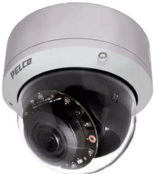
natural_image
Close-up of a PELCO security camera with visible lens and control buttons (no text or symbols on main subject)Dome (IMP831-1x) Models
C1369M (11/18)
Contents
Contents....3
Important Notices 5
Legal Notice 5
Regulatory Notices 5
Warranty Statement 5
Video Quality Caution 5
Open Source Software Notice 5
Description....6
System Model Numbers 6
Recommended mounts 6
Optional Accessories 6
Getting Started....6
Dome Camera Models 7
Supplied Parts List 7
User-Supplied Parts List 7
Product Label 7
Product Overview....8
Installation....9
Installing the Camera 9
In-Ceiling: Environmental with IMEICM-E 9
Pendant: Indoor and Environmental with IMEPM-E and WMVE-SR 12
Surface Mount: Indoor without a mount 13
Surface and Type 4X Mount: Environmental with IMEEBAP-E 13
Positioning the Camera 14
Alarm/Relay/Audio Port. 15
Cable Terminations 16
Ethernet Wiring Requirement for PoE 16
Accessing the Camera 17
Pelco Troubleshooting contact information 17
LEGAL NOTICE
SOME PELCO EQUIPMENT CONTAINS, AND THE SOFTWARE ENABLES, AUDIO/VISUAL AND RECORDING CAPABILITIES, THE IMPROPER USE OF WHICH MAY SUBJECT YOU TO CIVIL AND CRIMINAL PENALTIES. APPLICABLE LAWS REGARDING THE USE OF SUCH CAPABILITIES VARY BETWEEN JURISDICTIONS AND MAY REQUIRE, AMONG OTHER THINGS, EXPRESS WRITTEN CONSENT FROM RECORDED SUBJECTS. YOU ARE SOLELY RESPONSIBLE FOR INSURING STRICT COMPLIANCE WITH SUCH LAWS AND FOR STRICT ADHERENCE TO ANY/ALL RIGHTS OF PRIVACY AND PERSONALTY. USE OF THIS EQUIPMENT AND/OR SOFTWARE FOR ILLEGAL SURVEILLANCE OR MONITORING SHALL BE DEEMED UNAUTHORIZED USE IN VIOLATION OF THE END USER SOFTWARE AGREEMENT AND RESULT IN THE IMMEDIATE TERMINATION OF YOUR LICENSE RIGHTS THEREUNDER.
REGULATORY NOTICES
This device complies with Part 15 of the FCC Rules. Operation is subject to the following two conditions: (1) this device may not cause harmful interference, and (2) this device must accept any interference received, including interference that may cause undesired operation.
RADIO AND TELEVISION INTERFERENCE
This equipment has been tested and found to comply with the limits of a Class A digital device, pursuant to Part 15 of the FCC rules. These limits are designed to provide reasonable protection against harmful interference when the equipment is operated in a commercial environment. This equipment generates, uses, and can radiate radio frequency energy and, if not installed and used in accordance with the instruction manual, may cause harmful interference to radio communications. Operation of this equipment in a residential area is likely to cause harmful interference in which case the user will be required to correct the interference at his own expense.
Changes and Modifications not expressly approved by the manufacturer or registrant of this equipment can void your authority to operate this equipment under Federal Communications Commission's rules.
CAN ICES-3 (A)/NMB-3(A)
WARRANTY STATEMENT
For information about Pelco's product warranty and thereto related information, refer to www.pelco.com/warranty.
VIDEO QUALITY CAUTION
Frame Rate Notice Regarding User-Selected Options
Pelco systems are capable of providing high quality video for both live viewing and playback. However, the systems can be used in lower quality modes, which can degrade picture quality, to allow for a slower rate of data transfer and to reduce the amount of video data stored. The picture quality can be degraded by either lowering the resolution, reducing the picture rate, or both. A picture degraded by having a reduced resolution may result in an image that is less clear or even indiscernible. A picture degraded by reducing the picture rate has fewer frames per second, which can result in images that appear to jump or move more quickly than normal during playback. Lower frame rates may result in a key event not being recorded by the system.
Judgment as to the suitability of the products for users' purposes is solely the users' responsibility. Users shall determine the suitability of the products for their own intended application, picture rate and picture quality. In the event users intend to use the video for evidentiary purposes in a judicial proceeding or otherwise, users should consult with their attorney regarding any particular requirements for such use.
OPEN SOURCE SOFTWARE NOTICE
This product includes certain open source or other software originated from third parties that is subject to the GNU General Public License (GPL), GNU Library/Lesser General Public License (LGPL) and different and/or additional copyright licenses, disclaimers, and notices.
The exact terms of GPL, LGPL, and some other licenses are provided to you with this product. Please refer to the exact terms of the GPL and LGPL at http://www.fsf.org (Free Software Foundation) or http://www.opensource.org (Open Source Initiative) regarding your rights under said license. You may obtain a complete corresponding machine-readable copy of the source code of such software under the GPL or LGPL by sending your request to digitalsupport@pelco.com; the subject line should read Source Code Request. You will then receive an email with a link for you to download the source code.
This offer is valid for a period of three (3) years from the date of the distribution of this product by Pelco.
NOTE: This product is intended to be supplied by a Listed Power Adapter or DC power source marked "L.P.S." (or "Limited Power Source"), rated 12Vdc, 2A, 24Vac (50/60 Hz), 1.5A or POE 48Vdc, 0.6A, Tma = 60 degree C, and the altitude of operation = 2000m. If you need further assistance with purchasing the power source, please contact to PELCO, INC for further information.
Description
The GFC IMP Series dome cameras feature a P-Iris remote zoom lens for wide angle or long range surveillance needs. Autofocus capability ensures the camera can be automatically refocused when needed. Additionally, the GFC IMP Series features advanced color science and a mechanical IR cut filter for increased sensitivity in low-light installations.
The GFC IMP Series dome camera is easy to install, offers flexible mounting options, and uses a standard Web browser for easy remote setup and administration.
The GFC IMP Series dome camera easily connects to Pelco IP and hybrid systems such as VideoXpert and Digital Sentry version 7.3 (or later). The camera also conforms with ONVIF Profile S, Profile G, and Profile Q for connection with third-party software. Pelco offers an Application Programming Interface (API) and Software Developer's Kit (SDK) for interfacing with Pelco's IP cameras.
This document describes the installation and initial setup procedures to begin operating the camera. For more information about operating your camera, refer to the operation manual specific to the product.
NOTE: For additional information about product documentation in English and other languages, go to www.pelco.com and navigate to the GFC IMP Series website.
SYSTEM MODEL NUMBERS
| Back Box Resolution Lens Model Number Description | ||||
| Standard 8 MPx 3.5 to 10 mm IMP831-1ERS GFC 4K Environmental Dome IR Mic, with NEMA Type 4X Mounting Plate | ||||
| Standard 8 MPx 3.5 to 10 mm IMP831-1RS GFC 4K Dome IR Mic | ||||
RECOMMENDED MOUNTS
| Mounts Description |
| WMVE-SR Pendant mount arm, 1.5 inch, NPT, environmental, light gray |
| IMEICM-E Environmental in-ceiling mount, light gray |
| IMEEBAP-E Environmental 4S electrical box and Type 4X adapter |
| IMEPM-E Environmental pendant mount |
OPTIONAL ACCESSORIES
| Accessory Description | |
| PA101 Pole adapter for use with WMVE-SR wall mount | |
| MCS Series | Indoor, 24 VAC power supply |
| WCS Series Outdoor, 24 VAC power supply | |
| POE1AT-US | Single-port PoE+ midspan with US power cord |
| POE1AT-EU | Single-port PoE+ midspan with EU power cord |
| POE8ATN-US | 8-port PoE+ midspan with US power cord |
| POE8ATN-EU | 8-port PoE+ midspan with EU power cord |
| POE16ATN-US | 16-port PoE+ midspan with US power cord |
| POE16ATN-EU | 16-port PoE+ midspan with EU power cord |
GETTING STARTED
• Before installing your device, thoroughly familiarize yourself with the information in the installation section of this manual.
- Pelco recommends connecting the device to a network that uses a Dynamic Host Configuration Protocol (DHCP) server to address devices.
- Do not use a network hub when configuring the network settings for the device.
- To ensure secure access, place the device behind a firewall wen it is connected to a network.
SUPPLIED PARTS LIST
Qty Description
1 Camera
1 Installation manual
1 RoHS 10 (China only)
1 Power terminal block
2 Plastic expansion anchors
2 M4 x 25 mm self-tapping screws
1 Torx T20 security bit
1 Mounting plate (Type 4x) (Environmental model only)
6 8-32x.5 C-sink (Environmental model only)
4 M4x.7 x 6 mm screws (Environmental model only)
1 Important Safety Instructions document
USER-SUPPLIED PARTS LIST
In addition to the standard tools and cables required for a video security installation, you will need to provide the following items:
Qty Description
1 Conduit (if applicable)
1 Conduit adapters (if applicable)
1 RJ-45 connector to terminate wires
1 Cat5 (or higher) cable
1 #2 Philips screwdrivers
1 Tool for drilling
2 Driver 1/4" hex for security bit
1 Audio cable (optional)
1 Alarm cable (optional)
1 SD card, up to a 256 GB SanDisk Extreme ^® PLUS SDHC™ UHS-I MicroSD card, or with adapter to standard SD card size
PRODUCT LABEL
The product label lists the model number, date code, serial number, and Media Access Control (MAC) address. This information might be required for setup. A product label is located on the bottom of the camera and on the side of the product box.
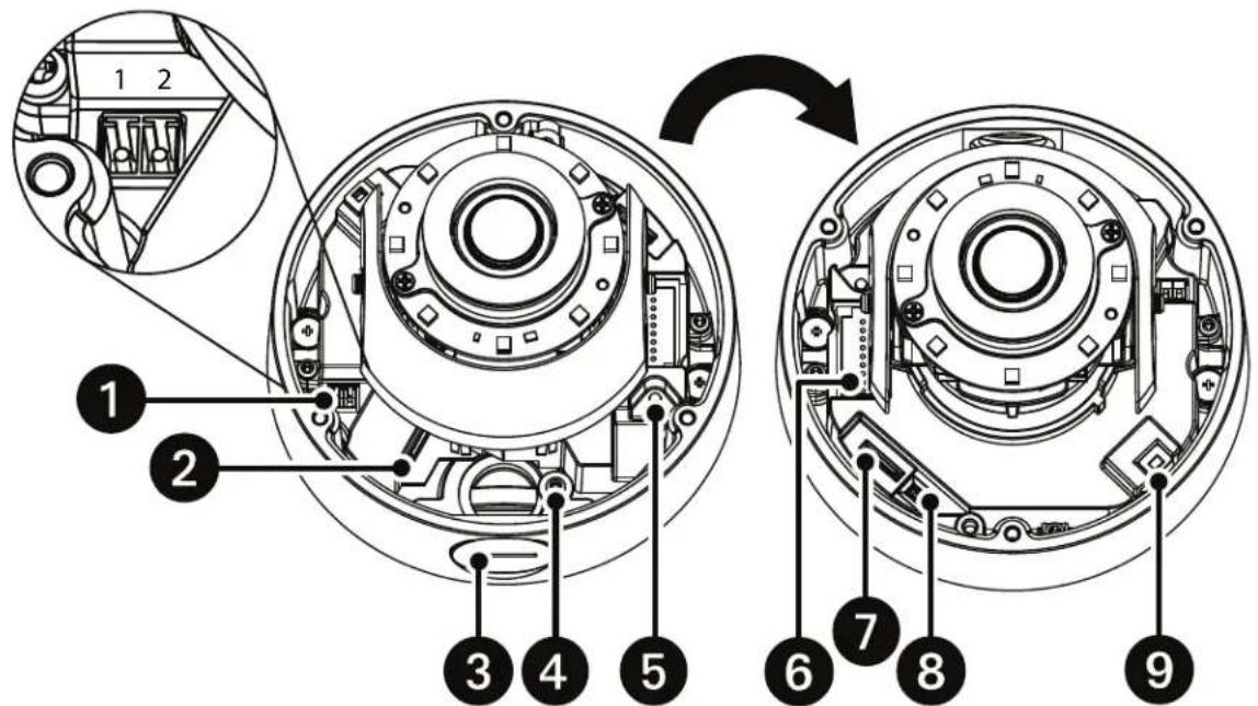
Figure 1. GFC IMP Series Dome Camera
- Power Connector: A two-pin connector for 12 VDC or 24 VAC. To wire the power connector, remove the green power male adapter that comes already inserted into the camera. Attach the wires per Figure 1 above (e.g. Pin 1 is 12 VDC or 24 VAC 1; Pin 2 is GND or 24 VAC 2.) with a small slotted screwdriver and then plug the adapter plug back into the camera.
- RJ-45 Network Port: Connects the camera to the IP network. also supplies power to the camera (POE), through the same connector. (Note: To purchase a power adapter, please contact Pelco for further information.)
- NPT 3/4"-14: Gland connection for the GFC IMP Series.
- Grounding Screw: If desired, used to ground the chassis.
- Reset Button: Reboots the camera or restores the camera's factory default settings. Press and release the reset button once to reboot the camera. Press and hold the reset button for 10 seconds to restore the camera to the factory default settings.
- Alarm/Relay/Audio Port: Connects to alarms, relays, and audio in/out.
- SD Card: Install the SD card into the card slot to store videos and snapshots. Do not remove the SD card when the camera is powered on a. To install the SD card, the dome cover must be taken off from the camera.
- Connector: Not being used.
- Microphone: Microphone for capturing sound.
INSTALLING THE CAMERA
You can install the GFC IMP Series dome cameras using one of the following methods:
• Installation in a suspended ceiling or a fixed ceiling. Refer to In-Ceiling: with IMEICM-E.
- Installation using a pendant mount. Refer to Pendant: Environmental with WMVE and IMEPM-E.
• Installation on a wall or a fixed ceiling. Refer to Surface Mount: Indoor without a mount or Environmental with IMEEBAP-E.
IN-CEILING: ENVIRONMENTAL WITH IMEICM-E
PARTS LIST SUPPLIED WITH THE MOUNT
Qty Description
1 In-Ceiling mount
1 Ceiling template
1 M4 mechanical screws
1 Trim ring
INSTALLATION GUIDE
- Optional: Remove the camera dome from camera housing by removing the anti-drop chain. Or, leave the protective film on the dome and use care.
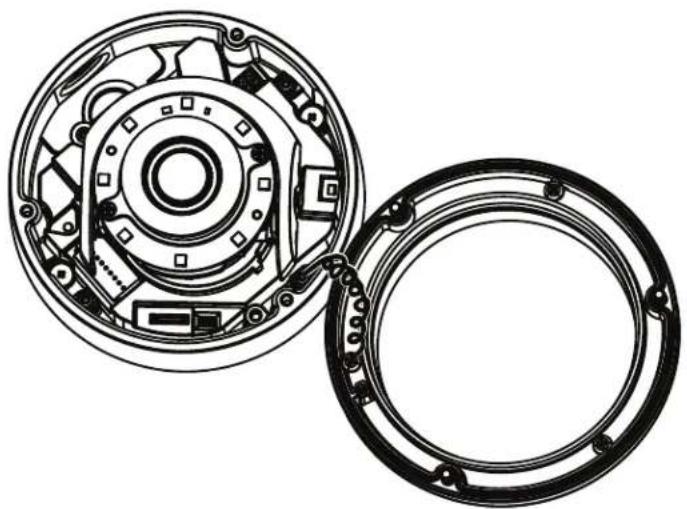
natural_image
Technical line drawing of a mechanical clutch assembly with internal components (no text or symbols)Figure 2. Anti-Drop Chain
- Secure the back box on the mounting bracket.
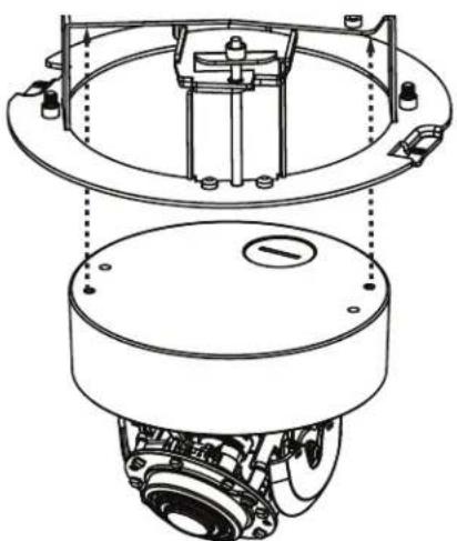
natural_image
Technical line drawing of a mechanical assembly with no visible text or symbolsFigure 3. Attaching the Back Box to the Mounting Bracket
- Determine the mounting location in the ceiling.
- Use the template to mark the hole on the ceiling or ceiling tile.
- Cut the hole for the camera.
- Pull the wiring through the hole.
- Move the conduit plug to the side or the top where needed to use the other hole for wire entry. Tighten the plug.
- Install the back box as follows:
a. Attach and seal the conduit as needed.
b. If using a conduit (not supplied): Feed the wires into the back box and plug the camera in.
c. Fold the rubber holders inside to clear the hole.
d. Push the back box through the hole.
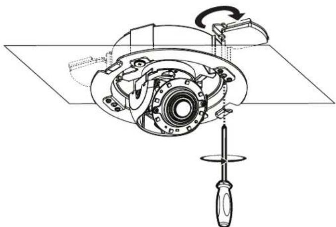
e. Rotate the screws clockwise to secure the bracket on the ceiling.
natural_image
Technical line drawing of a mechanical assembly with a screwdriver and rotating component (no text or symbols)Figure 4. Ceiling Bracket Rotation
- Adjust the angle of the lens by pan and tilt. Grasp the base of the lens assembly to adjust. When mounting the base, be mindful of the location of the microphone (See Figure 1) so that it is pointed toward areas of interest.
- Tighten the locking screw to secure the camera module position.
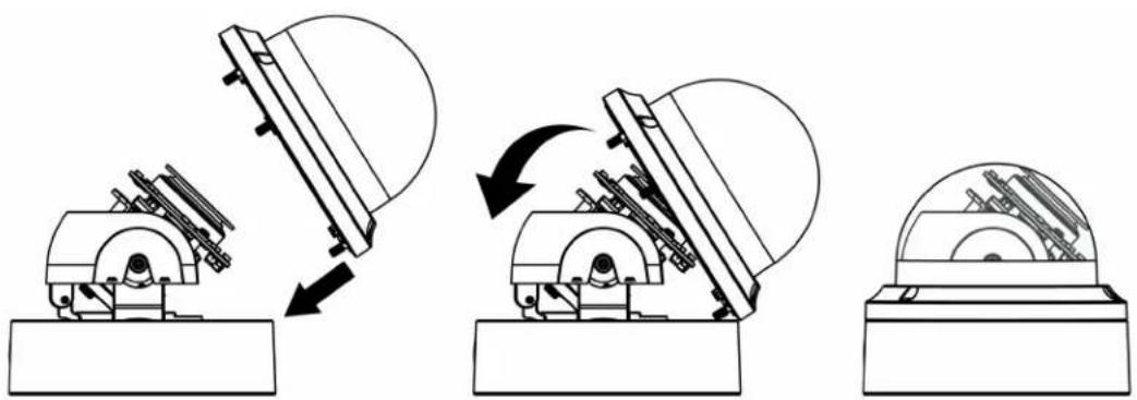
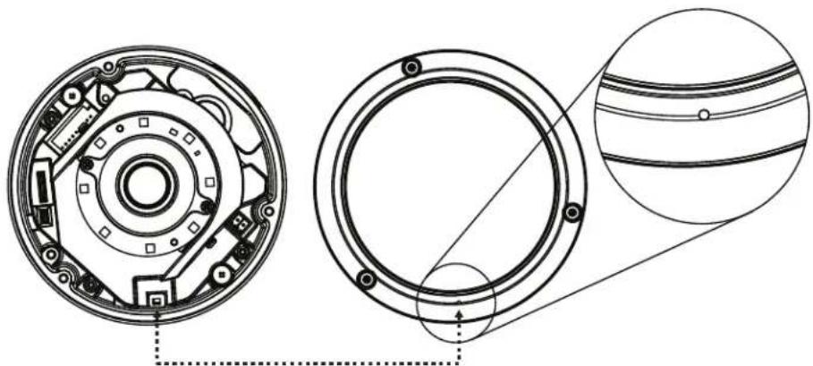
- Secure the anti-drop chain, put on the dome cover, and tighten the dome cover. When installing the lower dome or when putting it back, make sure the little hole in the lower dome matches the location and position of the microphone.
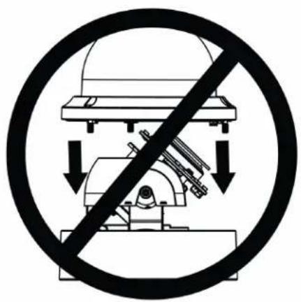
Figure 5. Incorrect Dome Cover Attachment Method
natural_image
Three-step diagram showing mechanical assembly with rotating components and directional arrows (no text or symbols)Figure 6. Correct Dome Cover Attachment Method
natural_image
Technical line drawing of a mechanical component showing front and side views with no visible text or symbolsFigure 7. Align Small Hole for Microphone
- Put on the trim ring and rotate it clockwise to secure the trim ring on the bracket.
PENDANT: INDOOR AND ENVIRONMENTAL WITH IMEPM-E AND WMVE-SR
PARTS LIST SUPPLIED WITH THE MOUNT
Qty Description
1 Pendant cap
2 M4x8 mechanical screws
INSTALLATION GUIDE
- Optional: Remove the camera dome from camera housing by removing the anti-drop chain.
- Put the conduit plug on the side of the camera box.
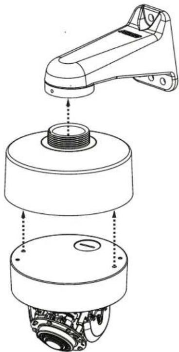
- Apply grease or Teflon tape to the pendant threads.
- Put the wiring through the hole on the top of the pendant cap into the camera.
- Screw on the pendant to the pipe or support arm.
- Add the support arm if purchased. Refer to the WMVE-SR installation manual on pelco.com for installing the wall mount arm.
- Place the camera back box or full camera into the pendant cap and adjust the camera back box by using the self-positioning pillars in the pendant cap. Twist until it snaps fully in. Secure the two M4 screws.
natural_image
Technical line drawing of a mechanical assembly showing a component being inserted into a housing (no text or symbols present)Figure 8. Dome Arm and Pendant
- Replace the camera on the back box (if removed for installation ease).
- Adjust the angle of the lens by pan and tilt by grasping the base. When mounting the base, be mindful of the location of the microphone (See Figure 1) so that it is pointed toward areas of interest.
- Tighten the locking screw to secure the camera module position.
- Secure the anti-drop chain, put on the dome cover, and tighten the dome cover (See Figure 5 and Figure 6). When installing the lower dome or when putting it back, make sure the little hole in the lower dome matches the location and position of the microphone (See Figure 7).
SURFACE MOUNT: INDOOR WITHOUT A MOUNT
- Prepare the wire entry holes through the plate and camera box. a. Remove the conduit plug if required and move to the hole not used.
- Remove the dome cover from the camera (optional).
- Pull the wire through the conduit hole into the camera.
- Mount the camera to the surface
- Adjust the angle of the lens by pan and tilt by the base. When mounting the base, be mindful of the location of the microphone (See Figure 1) so that it is pointed toward areas of interest.
- Tighten the locking screw to secure the camera module position.
- Install the dome lanyard if removed and then the dome cover and tighten the dome cover screws (See Figure 5 and Figure 6). When installing the lower dome or when putting it back, make sure the little hole in the lower dome matches the location and position of the microphone (See Figure 7).
SURFACE AND TYPE 4X MOUNT: ENVIRONMENTAL WITH IMEEBAP-E
INSTALLATION GUIDE
NOTE: The environmental camera is weather tight, rated IP66 if installed directly to a surface. So, this mounting plate is optional. However, to comply with a Type 4X outdoor rating, you must install the Type 4X mounting plate. (The Type 4X plate has a dual function to mount to junction boxes, so you can ignore the additional holes if not installing to a junction box.
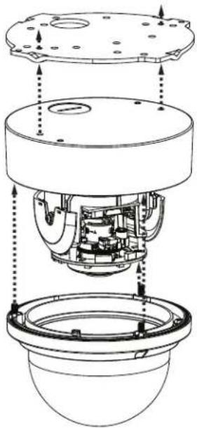
- Install the Type 4X Electrical Adapter Plate on the surface or Type 4X electrical box and secure the screws.
natural_image
Technical diagram of a mechanical assembly with internal components and alignment arrows (no text or labels)Figure 9. Adapter Plate
- Prepare the wire entry holes through the plate and camera box as follows: a. Remove the conduit plug if required and move to the hole not used.
- Remove the dome cover from the camera (optional).
- Install the camera to the plate.
- Pull the wire through the conduit hole into the camera.
Positioning the Camera
- Pan Adjustment: Rotate the lens base until you are satisfied with the field of view.
• Horizontal Rotation: Rotate 3D assembly in the lens base. - Tilt Adjustment: Lift to open the inner liner, and tilt the camera lens to your designed angle. Restore the inner liner back to its default position after adjustment.
• NOTE: Limitation for three axes position: - Pan range: 355^
- Rotate range: ± 100^
- Tilt range: -10^ to -90^
The 9-pin Alarm/Relay/Audio port has the following pins and pin assignments.
Pin Descriptions for Alarm/Relay/Audio Port
| No. | Connector Pin Definition | Remarks | |
| 1 Alarm and Audio I/O | 1 Line In+ (L/I+) | Audio In | |
| 2 Line In- (L/I-) | |||
| 3 Line Out+ {L/O+} | Audio Out | ||
| 4 Line Out- (L/O-) | |||
| 5 GND Ground | |||
| 6 Alarm Out NO (A/O N) | Alarm Connection7 Alarm Out COM (A/O C) | ||
| 8 Alarm In (A/I) | |||
| 9 GND Ground |
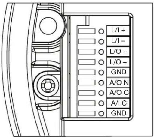
Alarm I/O
ETHERNET WIRING REQUIREMENT FOR POE
Connect a Cast5 cable or higher (Cat5e, Cat6) cable (not supplied) to the RJ-45 network connector. the 8-pin port includes video over Ethernet, and PoE for the camera. PoE injects power over the same cabling that carries the network data, eliminating the need for a separate power supply. This simplifies the installation and operation of the camera without affecting network performance.
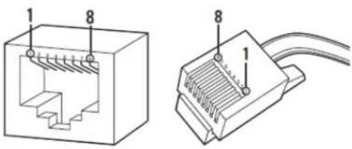
| PoE Mode A PoE Mode B | |||
| Pin | Function | Pin Function | |
| 1 TX+, PoE 1-2 1 TX+ | |||
| 2 TX-, PoE 1-2 2 TX- | |||
| 3 RX+, PoE 3-4 3 RX+ | |||
| 4 Not used 4 PoE 1-2 | |||
| 5 Not used 5 PoE 1-2 | |||
| 6 RX-, PoE 3-4 6 RX- | |||
| 7 Not used 7 PoE 3-4 | |||
| 8 Not used 8 PoE 3-4 | |||
Anyone who access the camera can view live video. If you want to prevent users from viewing video without logging in, you must change the permissions for public users.
The recommended browsers for your camera are the latest version of Internet Explorer®, Microsoft™ Edge™, Google Chrome™ browser, or Mozilla® Firefox®. for supported browser versions, refer to the specification sheet.
- Open a web browser.
- Type the camera's IP address (192.168.0.20) or host name in your browser's address bar, and the press Enter.
NOTE: You can obtain your camera's IP address or access the camera using the Pelco Device Utility or VxToolbox software. If DHCP is enabled but a DHCP server is not on the network, the camera automatically assigns itself both an IPv4 link local address (169.254.x.x, where the lower two octets are random) and a 192.168.0.20 address. Additional cameras will assign themselves different IPv4 link local addresses and the next available 192.168.0xIP addresses in sequential order. For example, if three cameras are connected to a network without a DHCP server, the first camera to connect assigns itself the IP address 192.168.0.20, the second camera assigns itself 192.168.0.21, and the third camera assigns itself 192.168.0.22.
-
Click Login.
-
If needed, type your user name and password.
NOTE: For security purposes, it is recommended that you create a user account when you login to the camera for the first time.
- In its out-of-the-box configuration, the camera has no user name and password assigned. For security purposes, it is recommended that you set an administrative user name and password after initial configuration of the camera. Creation of an administrative user name changes the state of the camera to its "operational mode," where credentials must be provided in order to change its configuration.
- There is no provision for recovering a forgotten administrator user name or password. The camera can be restored to its out-of-the-box, no-password configuration by powering down, depressing the reset button with an object such as a paper clip, and holding the button down for at least five seconds while power the camera back up.
NOTE: The Reset button for the camera is located near the relay/alarm block.
- If a user name and password exist, a Login link appears in the upper right area of your web browser.
- Click Log In.
PELCO TROUBLESHOOTING CONTACT INFORMATION
If the instructions provided fail to solve your problem, contact Pelco Product Support at 1-800-289-9100 (USA and Canada) or +1-559-292-1981 (international) for assistance. Be sure to have the serial number available when calling.
Do not try to repair the unit yourself. Leave maintenance and repairs to qualified technical personnel only.
REVISION HISTORY
Manual # Date Comments
C1369M 11/18 Original version.
Pelco, the Pelco logo, and other trademarks associated with Pelco products referred to in this publication are trademarks of Pelco, Inc. or its affiliates.
ONVIF and the ONVIF logo are trademarks of ONVIF Inc. All other product names and services are the property of their respective companies.
Product specifications and availability are subject to change without notice.
© Copyright 2018, Pelco, Inc.
All rights reserved.

by Schneider Electric
- GFC IMP Series Dome Cameras
- Contents
- LEGAL NOTICE
- REGULATORY NOTICES
- RADIO AND TELEVISION INTERFERENCE
- WARRANTY STATEMENT
- VIDEO QUALITY CAUTION
- Frame Rate Notice Regarding User-Selected Options
- OPEN SOURCE SOFTWARE NOTICE
- Description
- SYSTEM MODEL NUMBERS
- RECOMMENDED MOUNTS
- OPTIONAL ACCESSORIES
- GETTING STARTED
- SUPPLIED PARTS LIST
- Qty Description
- USER-SUPPLIED PARTS LIST
- PRODUCT LABEL
- INSTALLING THE CAMERA
- IN-CEILING: ENVIRONMENTAL WITH IMEICM-E
- PARTS LIST SUPPLIED WITH THE MOUNT
- INSTALLATION GUIDE
- PENDANT: INDOOR AND ENVIRONMENTAL WITH IMEPM-E AND WMVE-SR
- SURFACE MOUNT: INDOOR WITHOUT A MOUNT
- SURFACE AND TYPE 4X MOUNT: ENVIRONMENTAL WITH IMEEBAP-E
- Positioning the Camera
- ETHERNET WIRING REQUIREMENT FOR POE
- PELCO TROUBLESHOOTING CONTACT INFORMATION
- REVISION HISTORY
- Manual # Date Comments
Brand : Pelco
Model : GFC IMP831-1ERS
Category : Security Camera