Sarix Enhanced IBE322-1I - Security Camera Pelco - Free user manual and instructions
Find the device manual for free Sarix Enhanced IBE322-1I Pelco in PDF.


| Product Type | Indoor Bullet IP Security Camera |
| Model | Pelco Sarix Enhanced IBE322-1I |
| Resolution | 3 Megapixel (2048 x 1536) |
| Lens | Varifocal, 9-22 mm, manual zoom and focus |
| IR Illumination | Adaptive IR up to 30 meters (98 ft) |
| Video Compression | H.264, H.265, MJPEG |
| Day/Night | True Day/Night with mechanical IR cut filter |
| Wide Dynamic Range | SureVision 3.0 technology with WDR and anti-bloom |
| Power Supply | PoE (IEEE 802.3af), 12 VDC, or 24 VAC (auto-sensing) |
| Power Consumption | 12.9 W max (PoE) |
| Network Interface | 10/100 Base-T, RJ-45 |
| Onboard Storage | microSD slot, up to 128 GB (SanDisk Extreme PLUS recommended) |
| Mounting Options | Surface mount (ceiling/wall), optional wall mount (IBEWLMT-I) or pole mount (IBEPLMT-E) |
| Operating Temperature | 0°C to 50°C (32°F to 122°F) for indoor model |
| Dimensions (Camera Only) | Approx. 200 mm x 80 mm (7.9 in x 3.1 in) without bracket |
| Weight (Camera Only) | Approx. 1.0 kg (2.2 lb) |
| Protocols | IPv4, IPv6, TCP, UDP, HTTP, HTTPS, DHCP, DNS, ONVIF Profile S/G/Q |
| Warranty | Refer to www.pelco.com/warranty for details |
Frequently Asked Questions - Sarix Enhanced IBE322-1I Pelco
User questions about Sarix Enhanced IBE322-1I Pelco
0 question about this device. Answer the ones you know or ask your own.
Ask a new question about this device
Download the instructions for your Security Camera in PDF format for free! Find your manual Sarix Enhanced IBE322-1I - Pelco and take your electronic device back in hand. On this page are published all the documents necessary for the use of your device. Sarix Enhanced IBE322-1I by Pelco.
USER MANUAL Sarix Enhanced IBE322-1I Pelco
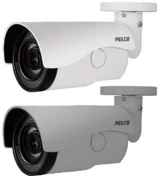
Next Gen Sarix® Enhanced IBE Series Bullet Cameras
natural_image
Exterior view of two PELCO security cameras (no text or symbols visible on the camera body)Installation Manual C1334M 7/17
Contents
Important Notices .... 3
Regulatory Notices....3
Radio and Television Interference ....3
Korean Class A EMC 3
Warranty Statement .... 3
UL Safety Notices....4
Introduction....5
Models....6
Recommended Mounts 6
Getting Started....7
Bullet Camera Models 8
Supplied Parts List 8
User-Supplied Parts List 8
Product Label 8
Product Overview....9
Installation 10
MicroSD Card Slot / Default Button....10
All-In-One Cable....12
Camera Cabling....13
Mounting the Camera....14
Surface Mount: Ceiling or Wall....15
Installation Guide....15
Wall Mount: Installation with Indoor (IBEWLMT-I) and Environmental (IBEWLMT-E)
Wall Mount....17
Supplied Parts List....17
User-Supplied Parts List 17
Installation Guide....18
Pole Mount: Installation with Environmental (IBEPLMT-E) Pole Mount....21
Supplied Parts List 21
User-Supplied Parts List 21
Installation Guide....21
Cable Terminations 26
Ethernet Wiring Requirement for PoE....26
IP Address Settings....27
Logging On to the Camera 27
Pelco Troubleshooting Contact Information 27
Important Notices
For more information about Pelco's product-specific important notices and thereto related information, refer to www.pelco.com/legal.
Regulatory Notices
This device complies with Part 15 of the FCC Rules. Operation is subject to the following two conditions: (1) this device may not cause harmful interference, and (2) this device must accept any interference received, including interference that may cause undesired operation.
Radio and Television Interference
This equipment has been tested and found to comply with the limits of a Class A digital device, pursuant to Part 15 of the FCC rules. These limits are designed to provide reasonable protection against harmful interference when the equipment is operated in a commercial environment. This equipment generates, uses, and can radiate radio frequency energy and, if not installed and used in accordance with the instruction manual, may cause harmful interference to radio communications. Operation of this equipment in a residential area is likely to cause harmful interference in which case the user will be required to correct the interference at his own expense.
Changes and modifications not expressly approved by the manufacturer or registrant of this equipment can void your authority to operate this equipment under Federal Communications Commission's rules.
CAN ICES-3(A)/NMB-3(A).
Korean Class A EMC
For information about Pelco's product warranty and thereto related information, refer to www.pelco.com/warranty.
Installation in Environmental Air Space, 4.7.3.1
The following statement or equivalent shall be marked on the product or provided in the Installation Instructions: "Suitable for use in environmental air space in accordance with Section 300-22(C) of the National Electrical Code, and Sections 2-128, 12-010(3) and 12-100 of the Canadian Electrical Code, Part 1, CSA C22.1."
UL Safety Notices
This product is intended to be supplied by a Listed Power Unit marked "L.P.S." (or "Limited Power Source") and rate output 24Vac, 50/60Hz, 1.28 minimum or 48 Vdc, 0.35A minimum.
The product shall be installed by a qualified service person and the installation shall conform to local codes.
Replaceable Batteries
CAUTION: Risk of Explosion if Battery is replaced by an Incorrect Type. Dispose of Used Batteries According to the Instructions.
Introduction
The Next Gen Sarix® IBE Series IP cameras feature SureVision 3.0 technology that seamlessly deliver advanced low-light performance with Pelco's Wide Dynamic Range (WDR) and anti-bloom technologies that operate simultaneously. They are part of Pelco's Enhanced (E) range of cameras, providing industry-leading image quality and performance.
The Next Gen IBE Series Bullet Camera is easy to install, offers flexible mounting options, and uses a standard Web browser for easy remote setup and administration.
The Next Gen IBE Series Bullet Camera easily connects to Pelco IP and hybrid systems such as VideoXpert™, Endura® version 2.0 (or later), and Digital Sentry® version 7.3 (or later). The camera is also conformant with ONVIF Profile S, Profile G, and Profile Q for connection with third-party software. Pelco offers an Application Programming Interface (API) and Software Developer's Kit (SDK) for interfacing with Pelco's IP cameras.
This document describes the installation and initial setup procedures to begin operating the camera. For more information about operating your camera, refer to the operation manual specific to the product.
NOTE: For additional information about product documentation in English and other languages, go to www.pelco.com/sarix and navigate to the Next Gen IBE Series Bullet Camera website.
Models
IBE129-11 Indoor, 3 \~ 9 mm focal range, with IR illumination, 1MPx, white
IBE129-1R Environmental, 3 \~ 9 mm focal range, with IR illumination, 1MPx, light gray
IBE229-11 Indoor, 3 \~ 9 mm focal range, with IR illumination, 2MPx, white
IBE229-1R Environmental, 3 \~ 9 mm focal range, with IR illumination, 2MPx, light gray
IBE222-11 Indoor, 9 \~ 22 mm focal range, with IR illumination, 2MPx, white
IBE222-1R Environmental, 9 \~ 22 mm focal range, with IR illumination, 2MPx, light gray
IBE329-11 Indoor, 3 \~ 9 mm focal range, with IR illumination, 3MPx, light gray, white
IBE329-1R Environmental, 3 \~ 9 mm focal range, with IR illumination, 3MPx, light gray
IBE322-11 Indoor, 9 \~ 22 mm focal range, with IR illumination, 3MPx, white
IBE322-1R Environmental, 9 \~ 22 mm focal range, with IR illumination, 3MPx, light gray
Recommended Mounts
IBEPLMT-E Pole mount, environmental, light gray
IBEWLMT-E Wall mount, environmental, light gray
IBEWLMT-I Wall mount, indoor, white
Getting Started
Before installing your device, thoroughly familiarize yourself with the information in the installation section of this manual.
NOTES:
- Pelco recommends connecting the device to a network that uses a Dynamic Host Configuration Protocol (DHCP) server to address devices.
- Do not use a network hub when configuring the network settings for the device.
• To ensure secure access, place the device behind a firewall when it is connected to a network.
Bullet Camera Models
Supplied Parts List
Qty Description
1 Bullet camera
1 Wall mount junction box (optional)
1 Power adapter plug (optional)
1 I/O adapter plug (optional)
3 M4 x 25 mm self-tapping screws
3 Plastic screw anchors
1 Torx T20 security bit
1 Next Gen IBE Series Bullet Camera Installation Manual
1 Important Safety Instructions sheet
1 Resources sheet
User-Supplied Parts List
In addition to the standard tools and cables required for a video security installation, you will need to provide the following items:
Qty Description
1 Cat 5 (or higher) cable with RJ-45 connector; ensure that the cable is terminated for your application (PoE or non-PoE)
1 #2 Philips and flathead screwdriver
1 Power cable (This is necessary if PoE is not available.)
1 microSD card, up to 128 GB SanDisk Extreme® PLUS SDHC™ UHS-I microSD card
1 Driver for included security bit (1/4" hex drive)
1 Alarm cable (optional)
1 Audio cable (optional)
1 Tool for drilling
Product Label
The product label lists the model number, date code, serial number, and Media Access Control (MAC) address. This information might be required for setup. A product label is located on the bottom of the camera and on the side the product box.
Product Overview
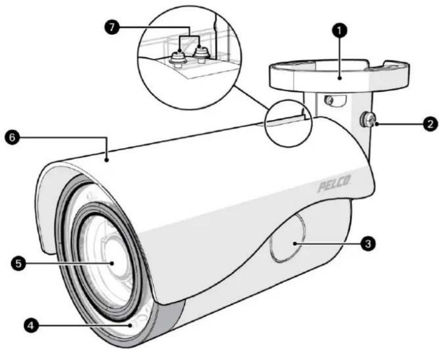
Next Gen IBE Series Bullet Camera
(1) Mounting Base: Use the mounting base to surface mount the camera or mount with one of the optional mounting accessories (pole mount or wall mount).
(2) Set Screws: One of two set screws to secure after aiming the camera.
(3) SD Card Access: Onboard micro SD card storage up to 128 GB.
(4) Infrared and Camera Status LEDs: The Next Gen IBE Series Bullet Camera includes adaptive IR illumination up to 30 meters. There are LED lights in a circle along the outer edge of the camera.
The Next Gen IBE Series Bullet Camera also includes a Camera Status LED which appears red at power on, changes to flashing green through boot up, and then it turns off when the camera is in normal operation.
(5) Camera Lens: Built-in, varifocal, 3-9 mm or 9-22 mm lens.
(6) Sun Shield: Plastic sun shield shades light while helping with heat control.
(7) Screws: Two screws to fix the sun shield after adjustment.
Installation
MicroSD Card Slot and Default Button
Insert the microSD card into the card slot to store videos and snapshots. Do not remove the microSD card when the camera is powered on.
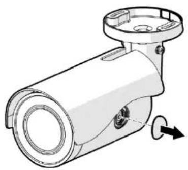
- Use a flathead screwdriver to remove the round cap covering the access hole on the side of the camera.
natural_image
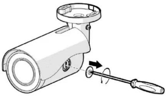
Technical line drawing of a cylindrical mechanical component with mounting flanges and a rotation arrow (no text or symbols)- Using a Torx screwdriver, unscrew the internal cover.
natural_image
Technical illustration of a mechanical device with a wrench and rotating knob (no text or symbols)NOTE: To record 24/7 continuously with the microSD card, contact the manufacturer of the microSD card for information regarding its reliability and life expectancy.
The Default Button is located under the internal cover along with the microSD card slot. Use this button to reset the camera to factory defaults.
- With the camera powered on, press and hold the Default Button with a proper tool for at least 20 seconds to restore the camera to factory default settings. Re-attach the internal metal cap and exterior round cap.
All-In-One Cable
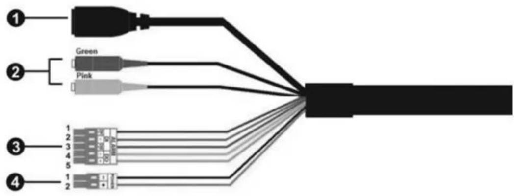
| No | Cable | Pin | Definition | Remarks | |
| 1 | Ethernet | - | |||
| 2 | Audio I/O | Green | Audio Out | Two-way audio transmission | |
| Pink | Audio In | ||||
| 3 | Alarm I/O(5-position Terminal Block) | 1 | Alarm In 2 + | Alarm connection | |
| 2 | Alarm In – (common) | ||||
| 3 | Alarm In 1 + | ||||
| 4 | Alarm Out – | ||||
| 5 | Alarm Out + | ||||
| 4 | Power (DC 12V / AC 24V)(2-position Terminal Block) | 1 | DC 12V – | AC 24V | Power connection |
| 2 | DC 12V + | AC 24V | |||
Camera Cabling
Before connecting cables, make sure that all cables and the power adaptor are placed in dry and well-waterproofed environments (e.g. waterproof boxes).
Power Connection:
Connect a DC 12V / AC 24V adapter to the 2-pin terminal block of the All-In-One cable and the power outlet. Or, connect the Ethernet cable to the Ethernet connector of the All-In-One cable, and plug the other end of the cable into a PoE supply. It is not recommended to use dual power.
Ethernet Cable Connection:
Connect one end of the Ethernet cable to the Ethernet connector of the All-In-One cable, and plug the other end of the cable to the network switch or PC.
NOTE: When connecting the camera directly to a PC, you may need to use an Ethernet crossover cable.
NOTE: Check the status of the link indicator and the activity indicator LEDs. If the LEDs are unlit, please check the LAN connection. A green link light indicates a good network connection. An orange activity light flashes to indicate network activity.
Mounting the Camera
You can install the Next Gen IBE Series Bullet Cameras using one of the following mounting methods:
- Camera can mount directly to the wall.
• Refer to the section Surface Mount: Ceiling or Wall.
- Installation using a wall mount junction box (optional accessory).
- Refer to the section Wall Mount Accessory: Installation with Indoor (IBEWLMT-I) and Environmental (IBEWLMT-E) Wall Mount.
- Installation using a pole mount junction box (optional accessory).
- Refer to the section Pole Mount Accessory: Installation with Environmental (IBEPLMT-E) Pole Mount.
Surface Mount: Ceiling or Wall
Installation Guide
The Next Gen IBE Series Bullet Camera can be installed directly on a wall or ceiling with the integrated 2-axis adjustable bracket mount.
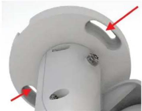
- Place the camera at the installation location. On the ceiling or wall, mark the position of the two screw holes of the camera.
natural_image
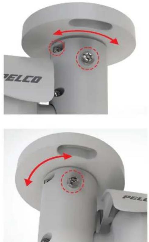
Close-up of a white mechanical component with two red arrows pointing to features, no visible text or symbols.If the screw holes are blocked by the camera body, loosen the three screws shown in the pictures below, but do not detach the screws. Then rotate the camera body to reach the screw holes.
natural_image
Close-up of a mechanical component with red arrows indicating motion or force, showing two views (top and side) with no visible text or symbols.-
At the center of the two marked holes, draw a cable entry hole with 30 mm diameter and drill the cable entry hole. Then drill a hole for the screw (or supplied plastic screw anchor if necessary).
-
Thread the All-In-One cable through the cable entry hole. Refer to Camera Cabling section for cable connections.
-
Match the camera with the holes (or plastic screw anchors). Fasten the camera with the supplied M4x31 self-tapping screws.
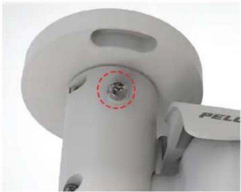
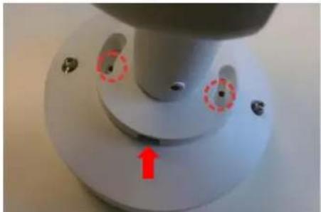
- Use a Torx screwdriver to loosen the two screws indicated in the picture below. Do not detach the screws. Rotate the camera and point the camera to a desired direction. Lastly, tighten the two screws to secure the camera.
natural_image
Close-up of a white plastic mechanical component with a red dashed circle highlighting a small circular feature, labeled 'PELL' on the side (no other text or symbols visible)Wall Mount: Installation with Indoor (IBEWLMT-I) and Environmental (IBEWLMT-E) Wall Mount
Supplied Parts List
Qty Description
1 Wall mount junction box
3 Plastic screw anchors
3 M4 x 25mm self-tapping screws
5 M4 x 12mm machine screws
3 Waterproof washers
User-Supplied Parts List
Qty Description
1 Bullet camera
1 Ethernet cable
1 Power cable (necessary if PoE is not available)
2 Alarm cable (optional)
3 Audio cable (optional)
1 Torx T20 security bit (supplied with camera)
1 Tool for drilling
1 Phillips and flathead screwdriver
1 Driver 14 " hex for security bit
Installation Guide
- Loosen the two screws in the picture below with a screwdriver and detach the wall mount junction box (IBEWLMT-I or IBEWLMT-E) cover.
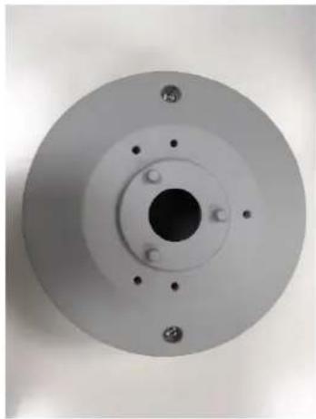
natural_image
Circular mechanical component with central hole and four mounting holes (no text or symbols visible)- Place the wall mount junction box at the preferred installation location. On the wall, mark the position of the two screw holes indicated in the picture below. Drill a hole on each marked screw hole and insert the plastic screw anchors (if necessary) into the drilled holes.

natural_image
Top-down view of a mechanical component with red annotations highlighting features (no text or symbols visible)- Place the supplied waterproof washers on the two screw holes. Match the two screw holes on the wall mount junction box with the plastic screw anchors (if used) at the installation location. Then, fasten the wall mount junction box to the wall with the supplied M4 self-tapping screws.
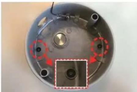
natural_image
Top-down view of a mechanical component with red circular highlights and a magnified inset showing a circular feature (no text or symbols visible)- Loosen the cable clamp slightly. Remove the internal portion of the rubber plug from the cable entry hole of the wall mount junction box cover.
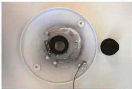
natural_image
Top-down view of a circular mechanical component with internal components and a separate black circular component (no text or symbols visible)- Thread the connectors of the All-In-One cable of the camera one-by-one through the cable entry hole.
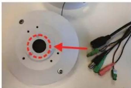
natural_image
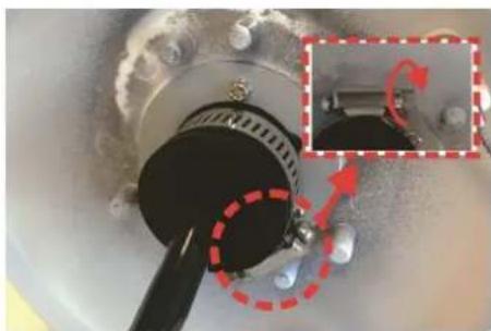
Close-up of a white circular electronic component with a red dashed ring and multiple colored wires attached (no visible text or symbols)- Open the rubber back plug. Place over the cable and insert the rubber plug back to the cable entry hole and use a flathead screwdriver to tighten the stainless steel clamp by turning the knob clockwise. Make sure there is no gap between the All-In-One cable and the cable entry hole.
natural_image
Close-up of a mechanical component with red dashed arrows indicating rotation or adjustment, no visible text or symbols- Route the exterior cables into the box from the side or back conduit hole. If necessary, unscrew the coin plug to access a conduit hole. Move the plug to the unused conduit hole. Connect the cables.
- Seal the conduit to the wall mount junction box cover.
-
Arrange the All-In-One cable neatly.
-
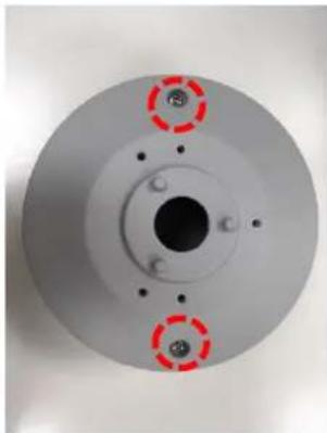
Adjust the position of the wall mount junction cover properly and fasten the two screws to tighten the cover.
natural_image
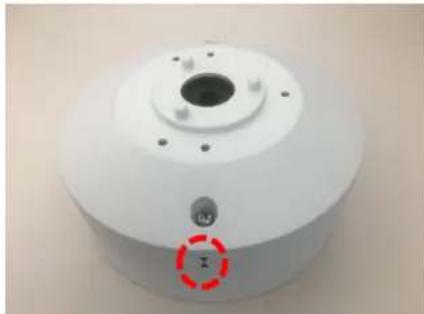
Circular mechanical component with three red circular features and central bore (no text or symbols visible)NOTE: When securing the wall mount junction box cover, you must align the two arrow marks with each other to ensure the cover is properly aligned.
natural_image
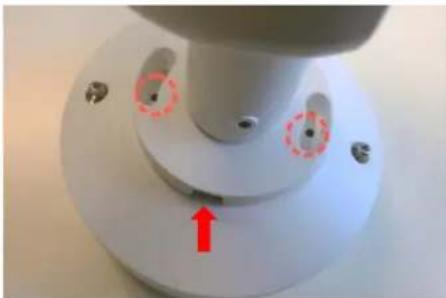
Close-up of a white cylindrical mechanical component with a central hole and mounting holes, marked with a red circle containing the letter 'I' (no text or symbols on the object itself)- Align the two screw holes on the camera with the screw holes on the wall mount junction box cover and fasten the camera with the M4 machine screws. The drainage hole should point down when installing horizontally.
natural_image
Close-up of a white mechanical component with circular features and a red arrow pointing to a feature (no text or symbols visible)- Rotate and point the camera to a desired direction and tighten the two set screws as shown below. The wall mount junction box installation is complete.
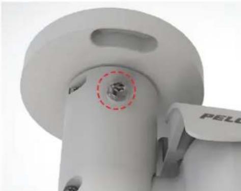
natural_image
Close-up of a white mechanical component with a red dashed circle highlighting a small circular feature, labeled 'PELL' on the side (no other text or symbols visible)Pole Mount: Installation with Environmental (IBEPLMT-E) Pole Mount
Supplied Parts List
Qty Description
1 Pole mount junction box
5 M4 x 12mm machine screws
2 Stainless steel rings
NOTE: The supplied stainless steel rings apply to poles with the diameter from 70 to 180mm.
User-Supplied Parts List
Qty Description
1 Bullet camera
1 Ethernet cable
1 Power cable (necessary if PoE is not available)
1 Alarm cable (optional)
1 Audio cable (optional)
1 Phillips and flathead screwdriver
Installation Guide
- Loosen the two screws in the photo below and detach the pole mount junction box cover.
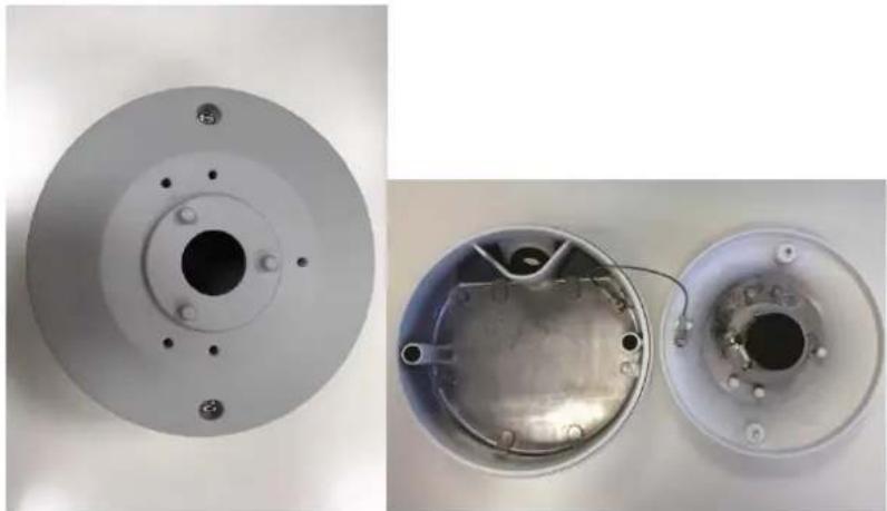
natural_image
Two views of a mechanical component: top shows a circular flange with bolt holes, bottom shows an open metallic housing with internal components and wiring (no text or symbols visible)- Remove the internal rubber plug from the cable entry hole of the pole mount junction box cover.
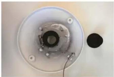
natural_image
Top-down view of a circular mechanical component with a central black ring and attached wires, no visible text or symbols.- Thread the connectors of the All-In-One cable of the camera one by one through the cable entry hole.
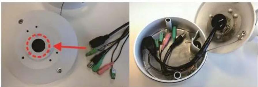
natural_image
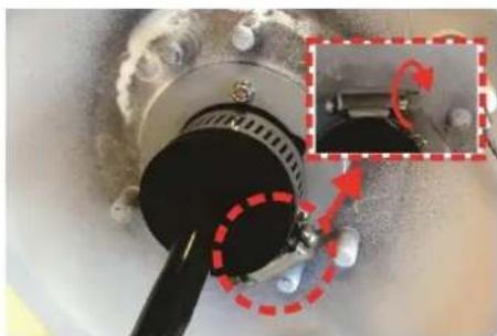
Two views of a mechanical or electronic device: one showing a circular component with red dashed line and arrow, the other showing internal wiring and connectors (no text or symbols visible)- Insert the rubber plug back to the cable entry hole and use a flathead screwdriver to tighten the stainless steel ring by turning the knob clockwise. Make sure there's no gap between the All-In-One cable and cable entry hole.
natural_image
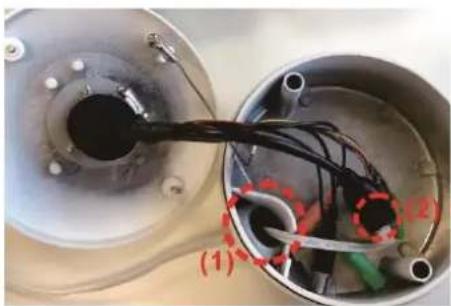
Close-up of a mechanical component with red dashed circles highlighting a highlighted section (no text or symbols visible)- Connect the required cables (e.g. Ethernet cable) (#1 and #2 in the picture below) to the connectors of the All-In-One cable.
natural_image
Close-up of a metallic mechanical component with internal wiring and a black connector, labeled (1) and (2), no readable text or symbols beyond labels.-
Arrange the All-In-One cable neatly.
-
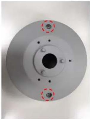
Adjust the position of pole mount junction box cover properly and fasten the two screws to tighten the cover.
natural_image
Circular mechanical component with central bore and four mounting holes, no visible text or symbolsNOTE: When securing the pole mount junction box cover, you must align the two arrow marks with each other to ensure the cover is properly fixed.
natural_image
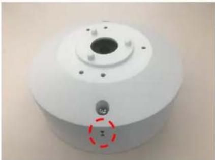
Close-up of a white cylindrical mechanical component with a central hole and a red dashed circle highlighting a small feature (no text or symbols visible)- Align the two screw holes of the camera with the screw holes on the pole mount junction box cover and fasten the camera with the M4 machine screws. The drainage hole should point down when installing horizontally.
natural_image
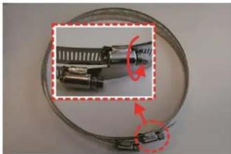
Close-up of a mechanical component with red arrows and circular features, no visible text or symbols- Loosen the knobs on the stainless steel rings by turning them counterclockwise with a flathead screwdriver.
natural_image
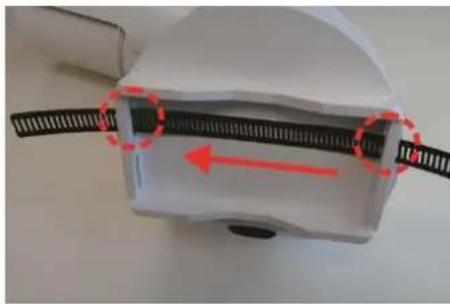
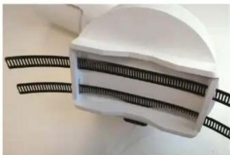
Close-up of a metallic hose with attached connectors, showing internal components and red directional arrows (no text or symbols)- Insert the stainless steel rings into the holes on the back of the pole mount junction box.
natural_image
Close-up of a white plastic device with black screw leads and a red arrow indicating direction (no text or symbols visible)NOTE: When installing the pole mount junction box on the pole, the cable entry hole must be at the bottom side to ensure it is waterproof.
natural_image
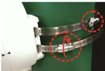
White hard hat with black textured bands, placed on a surface (no text or symbols visible)- Place the pole mount junction box at the preferred installation location. Circle around the pole with the stainless steel rings and turn the knobs clockwise with a flathead screwdriver until the stainless steel rings are firmly tightened.
natural_image
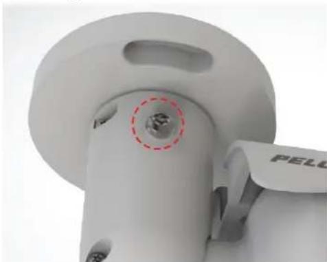
Close-up of a mechanical clamp or connector with red dashed circles highlighting a specific part (no text or symbols visible)- Rotate and point the camera to a desired direction and tighten the screws as shown below. The pole mount junction box installation is completed.
natural_image
Close-up of a white mechanical component with a red dashed circle highlighting a small circular feature, labeled 'PELL' on the side (no other text or symbols visible)Cable Terminations
Ethernet Wiring Requirement for PoE
Connect a Cat5 cable or higher (Cat5e, Cat6) cable (not supplied) to the RJ-45 network connector. The 8-pin port includes video over Ethernet, and PoE for the camera. PoE injects power over the same cabling that carries the network data, eliminating the need for a separate power supply. This simplifies the installation and operation of the camera without affecting network performance.
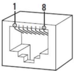
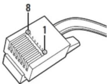
Table 1 Pin Definition
| PoE Mode A | PoE Mode B | ||||
| Pin | Function | Pin | Function | ||
| 1 | TxRx A + | DC + | 1 | TxRx A + | |
| 2 | TxRx A - | DC + | 2 | TxRX A - | |
| 3 | TxRx B + | DC - | 3 | TxRx B + | |
| 4 | TxRx C + | 4 | TxRx C + | DC + | |
| 5 | TxRx C - | 5 | TxRx C - | DC + | |
| 6 | TxRx B - | DC - | 6 | TxRx B - | |
| 7 | TxRx D + | 7 | TxRx D + | DC - | |
| 8 | TxRx D - | 8 | TxRx D - | DC - | |
IP Address Settings
If the camera is connected to a Dynamic Host Configuration Protocol (DHCP) network and DHCP is set to On, the server automatically assigns an IP address to the camera. The default setting for the camera is DHCP On. To set the camera's IP address manually, set DHCP to Off.
NOTE: When DHCP is on, but a DHCP server cannot be found:
- Next Gen Sarix Enhanced cameras will simultaneously support two IP addressing schemes: 169.254.x.x and 192.168.0.x (starting from 192.168.0.20).
The default IP address on subnet mask 255.255.0.0 is automatically assigned as 169.254.x.y where x and y will take a value from 0 to 255 randomly. Please note cameras on the same subnet will not be assigned the same IP address to avoid IP conflicts.
The device defaults to an address of 192.168.0.20 on a 255.255.255.0 subnet. If 192.168.0.20 is already in use on the network, the Sarix device will increment the address by one until it finds an unused address (for example, 192.168.0.21 if 192.168.0.20 is in use).
Logging On to the Camera
After logging on to the camera, you can view video from the Web user interface.
- Open the Web browser.
- Type the camera's IP address in the browser address bar. If you do not know the camera's IP address, you can locate it using the Pelco Device Utility software.
- When accessing the device in its initial out-of-the-box state, you will be prompted to set the initial administrator account credentials.
NOTE: The initial out-of-the-box state is also called "Factory Default State."
Factory Default State:
The ONVIF Profile Q specification requires that the camera accept any commands without authentication when in a Factory Default State. In this initial state there are no users defined and accessing the camera through the web interface will result in a prompt to set the initial administrator account.
Once the initial administrator account is created, the camera should immediately request login credentials and should begin requiring credentials for ONVIF API requests.
Clicking the Cancel button when setting the initial administrator account prompt will cause the initial login process to be temporarily bypassed, allowing you to continue to configure the camera without credentials. When the session becomes inactive (e.g. times out) or another session is started, the camera will once again prompt you to set up the initial administrator account.
- Click Log In.
Pelco Troubleshooting Contact Information
If the instructions provided fail to solve your problem, contact Pelco Product Support at 1-800-289-9100 (USA and Canada) or +1-559-292-1981 (International) for assistance. Be sure to have the serial number and model number available when calling.
Do not try to repair the unit yourself. Leave maintenance and repairs to qualified technical personnel only.

by Schneider Electric
Pelco by Schneider Electric
3500 Pelco Way Clovis, California 93612 USA
(800) 289-9100 Tel (800) 289-9150 Fax
+1 (559) 292-1981 International Tel
+1 (559) 348-1120 International Fax
www.pelco.com
Pelco, the Pelco logo, and other trademarks associated with Pelco products referred to in this publication are trademarks of Pelco, Inc. or its affiliates. ONVIF and the ONVIF logo are trademarks of ONVIF Inc. All other product names and services are the property of their respective companies. Product specifications and availability are subject to change without notice.
© Copyright 2015, Pelco, Inc. All rights reserved.
- Next Gen Sarix® Enhanced IBE Series Bullet Cameras
- Contents
- Important Notices .... 3
- Introduction....5
- Getting Started....7
- Product Overview....9
- Installation 10
- Cable Terminations 26
- IP Address Settings....27
- Logging On to the Camera 27
- Pelco Troubleshooting Contact Information 27
- Important Notices
- Regulatory Notices
- Radio and Television Interference
- Korean Class A EMC
- Installation in Environmental Air Space, 4.7.3.1
- UL Safety Notices
- Replaceable Batteries
- Introduction
- Models
- Recommended Mounts
- Getting Started
- NOTES:
- Bullet Camera Models
- Supplied Parts List
- Qty Description
- User-Supplied Parts List
- Product Label
- Product Overview
- Installation
- MicroSD Card Slot and Default Button
- All-In-One Cable
- Camera Cabling
- Power Connection:
- Ethernet Cable Connection:
- Mounting the Camera
- Surface Mount: Ceiling or Wall
- Installation Guide
- Wall Mount: Installation with Indoor (IBEWLMT-I) and Environmental (IBEWLMT-E) Wall Mount
- Pole Mount: Installation with Environmental (IBEPLMT-E) Pole Mount
- Cable Terminations
- Ethernet Wiring Requirement for PoE
- IP Address Settings
- Logging On to the Camera
- Factory Default State:
- Pelco Troubleshooting Contact Information
- Pelco by Schneider Electric
Brand : Pelco
Model : Sarix Enhanced IBE322-1I
Category : Security Camera