
D6010 - Video projector VIVITEK - Free user manual and instructions
Find the device manual for free D6010 VIVITEK in PDF.


| Product Type | DLP Video Projector |
| Brand | Vivitek |
| Model | D6010 |
| Native Resolution | WXGA (1280 x 800) |
| Brightness (Nominal) | 6000 ANSI Lumens |
| Contrast Ratio | 2000:1 (typical) |
| Lamp Type | Dual Lamp (user replaceable) |
| Lamp Life (Normal Mode) | 2000 - 2100 hours |
| Lamp Life (Eco Mode) | 2500 - 2600 hours |
| Color Wheel | 4-segment (standard), optional 6-segment |
| Lens Options | Interchangeable: GC805G, GB942G, GB940G, GB949G, GB957G |
| Lens Shift | Vertical +0.5V, Horizontal ±0.1H |
| Keystone Correction | Horizontal ±35°, Vertical ±40° (approx.) |
| Inputs | 1x VGA, 1x DVI-D, 1x BNC (5), 1x Component (RCA), 1x S-Video, 1x Composite, 3x Stereo Audio, 2x RCA Audio, 1x LAN (RJ-45), 1x RS-232 |
| Outputs | 1x VGA (Monitor Out), 1x Stereo Audio, 1x Screen Trigger |
| Built-in Speakers | 5W x 2 (stereo) |
| Power Consumption | 730W (Dual Normal), 570W (Dual Eco), 380W (Single Normal), 310W (Single Eco), <30W (Standby Normal), <5W (Standby Power Saving) |
| Dimensions (W x H x D) | 508 mm x 195 mm x 389 mm (20" x 7.7" x 15.3") |
| Weight | 17 kg (37.5 lb) |
| Supported Video Standards | NTSC, PAL, SECAM, HDTV (1080p/1080i/720p), SDTV (576p/576i/480p/480i) |
| Network Control | HTTP server, PJLink, RS-232 |
| Security | Kensington lock, security chain, PIN code lock |
| Maintenance | User-replaceable lamps, cleanable air filters (every 500 hours) |
Frequently Asked Questions - D6010 VIVITEK
User questions about D6010 VIVITEK
0 question about this device. Answer the ones you know or ask your own.
Ask a new question about this device
Download the instructions for your Video projector in PDF format for free! Find your manual D6010 - VIVITEK and take your electronic device back in hand. On this page are published all the documents necessary for the use of your device. D6010 by VIVITEK.
USER MANUAL D6010 VIVITEK
This publication, including all photographs, illustrations and software, is protected under international copyright laws, with all rights reserved. Neither this manual, nor any of the material contained herein, may be reproduced without written consent of the author.
© Copyright 2010
Disclaimer
The information in this document is subject to change without notice. The manufacturer makes no representations or warranties with respect to the contents hereof and specifically disclaims any implied warranties of merchantability or fitness for any particular purpose. The manufacturer reserves the right to revise this publication and to make changes from time to time in the content hereof without obligation of the manufacturer to notify any person of such revision or changes.
Trademark Recognition
Kensington is a U.S. registered trademark of ACCO Brand Corporation with issued registrations and pending applications in other countries throughout the world.
All other product names used in this manual are the properties of their respective owners and are acknowledged.
Important Safety Information
Congratulations on purchasing the Vivitek DLP ^® projector!
Important:
It is strongly recommended that you read this section carefully before using the projector. These safety and usage instructions will ensure that you enjoy many years of safe use of the projector. Keep this manual for future reference.
Symbols Used
Warning symbols are used on the unit and in this manual to alert you of hazardous situations.
The following styles are used in this manual to alert you to important information.
Note:
Provides additional information on the topic at hand.
Important:
Provides additional information that should not be overlooked.
Caution:
Alerts you to situations that may damage the unit.
Warning:
Alerts you to situations that may damage the unit, create a hazardous environment, or cause personal injury.
Throughout this manual, component parts and items in the OSD menus are denoted in bold font as in this example:
"Push the Menu button on the remote control to open the Main menu."
Remote Control
Some remote controls have a laser for pointing out items on a screen.
DANGER: Do not point the laser in the eyes. Doing so can damage the eyes permanently.
General Safety Information
Do not open the unit case. Aside from the projection lamp, there are no user-serviceable parts in the unit. For servicing, contact qualified service personnel.
➢ Follow all warnings and cautions in this manual and on the unit case.
The projection lamp is extremely bright by design. To avoid damage to eyes, do not look into the lens when the lamp is on.
Do not place the unit on an unstable surface, cart, or stand.
- Avoid using the system near water, in direct sunlight, or near a heating device.
Do not place heavy objects such as books or bags on the unit.
Power Safety
▶ Only use the supplied power cord.
Do not place anything on the power cord. Place the power cord where it will not be in the way of foot traffic.
Remove the batteries from the remote control when storing or not in use for a prolonged period.
Replacing the Lamp
Replacing the lamp can be hazardous if done incorrectly. See Replacing the Lamps on page 80 for clear and safe instructions for this procedure. Before replacing the lamp:
➢ Unplug the power cord.
➢ Allow the lamp to cool for about one hour.
Important Recycle Instructions:

Lamp(s) inside this product contain mercury. This product may contain other electronic waste that can be hazardous if not disposed of properly. Recycle or dispose in accordance with local, state, or federal Laws. For more information, contact the Electronic Industries Alliance at WWW.EIAE.ORG. For lamp specific disposal information check WWW.LAMPRECYCLE.ORG.
Cleaning the Projector
➢ Unplug the power cord before cleaning. See Cleaning the projector on page 77.
- Allow the lamp to cool for about one hour.
Regulatory Warnings
Before installing and using the projector, read the regulatory notices in the Regulatory Compliance section on page 104.
Symbol Explanations

DISPOSAL: Do not use household or municipal waste collection services for disposal of electrical and electronic equipment. EU countries require the use of separate recycling collection services.
Projector Installation Notice
➢ Place the projector in a horizontal position
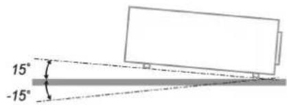
The tilt angle of the projector should not exceed 15 degrees, nor should the projector be installed in any way other than the desktop and ceiling mount, otherwise lamp life could decrease dramatically.


natural_image
Pure electrical circuit lines without any symbols- Allow at least 50 cm clearance around the exhaust vent.


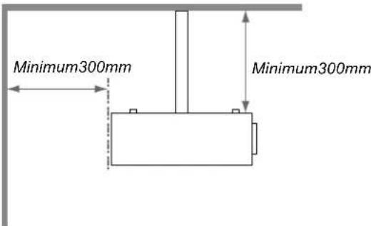
➢ Ensure that the intake vents do not recycle hot air from the exhaust vent.
When operating the projector in an enclosed space, ensure that the surrounding air temperature within the enclosure does not exceed 5 – 35°C while the projector is running, and the air intake and exhaust vents are unobstructed.
All enclosures should pass a certified thermal evaluation to ensure that the projector does not recycle exhaust air, as this may cause the device to shutdown even if the enclosure temperature is with the acceptable 5 – 35°C range.
Main Features
• Lightweight unit, easy to pack away and transport.
- Compatible with all major video standards including NTSC, PAL, and SECAM.
- A high brightness rating allows for presentations in daylight or in lit rooms.
• Supports resolutions up to UXGA at 16.7 million colors to deliver crisp, clear images.
- Flexible setup allows for front, rear projections.
• Line-of-vision projections remain square, with advanced keystone correction for angled projections.
- Input source automatically detected.
About this manual
This manual is intended for end users and describes how to install and operate the DLP projector. Wherever possible, relevant information—such as an illustration and its description—has been kept on one page. This printer-friendly format is both for your convenience and to help save paper, thereby protecting the environment. It is suggested that you only print sections that are relevant to your needs.
Table of Contents
INTRODUCTION....1
PACKING CHECKLIST .... 1
VIEWS OF PROJECTOR PARTS....2
Front-right View 2
Bottom view....3
TOP FEATURES....4
OSD Controls and Status LEDs 4
TERMINAL PANEL FEATURES....5
REMOTE CONTROL PARTS 7
REMOTE CONTROL OPERATING RANGE....9
PROJECTOR AND REMOTE CONTROL BUTTONS....9
Remote Control 9
SETUP AND OPERATION....10
INSERTING THE REMOTE CONTROL BATTERIES 10
INSTALLING OR REMOVING THE OPTIONAL LENS 11
Removing the Existing Lens From the Projector .... 11
Installing the New Lens....12
THROW DISTANCE AND SCREEN SIZE 13
INSTALLING THE OPTIONAL COLOR WHEEL 15
MAKING CONNECTIONS....17
Connecting Your PC or Macintosh Computer 17
Connecting an External Monitor 18
Connecting Your DVD Player with Component Output 19
Connecting Your VCR or Laser Disc Player 20
PROJECTING AN IMAGE (BASIC OPERATION)....21
TURNING ON THE PROJECTOR 21
Note on Startup Screen (Menu Language Select screen).... 22
SELECTING AN INPUT SOURCE 23
ADJUSTING THE PICTURE POSITION AND PICTURE SIZE 24
Adjusting Picture Position Manually 24
Lens Shift Adjustable Range 25
From the Remote Control Unit 26
Adjusting the Projector Level 28
OPTIMIZING AN RGB IMAGE AUTOMATICALLY....29
Adjusting the Image Using AUTO 29
ADJUSTING VOLUME UP AND DOWN 30
TURNING OFF THE PROJECTOR....31
About Direct Power Off 32
After Use 32
CONVENIENT FEATURES....33
TURNING OFF THE IMAGE AND SOUND 33
FREEZING A PICTURE 33
ADJUSTING THE FOCUS/ZOOM MANUALLY 34
Adjusting by Using the OSD Control Panel.... 34
CHANGING LAMP MODE....35
Changing Lamp Mode by Using the Projector's OSD Control Panel.... 35
GETTING INFORMATION.... 36
ADJUSTING POSITION/TOTAL DOTS/FINE SYNC 37
Adjusting Position/Total Dots/Fine Sync by using the OSD Control Panel 37
Correcting Keystone by Using the Remote Control 38
PREVENTING THE UNAUTHORIZED USE OF THE PROJECTOR 40
Locking the Projector 40
Unlocking the Projector....41
Navigating the OSD 43
MENU TREE 45
MENU ELEMENTS 47
INPUT MENU DESCRIPTIONS AND FUNCTIONS 48
ADJUST MENU DESCRIPTIONS AND FUNCTIONS....49
Image menu....49
Image options menu 50
Video menu 52
DETAIL SETTING MENU DESCRIPTIONS AND FUNCTIONS .... 55
Basic 55
White balance....57
Color correction....58
SETTING MENU DESCRIPTIONS AND FUNCTIONS 59
Basic 59
Installation....62
Network setting 67
Option 68
INFORMATION MENU DESCRIPTIONS AND FUNCTIONS 72
Usage time 72
Input 73
Network....74
Version 75
RESET MENU DESCRIPTIONS AND FUNCTIONS....76
MAINTENANCE....77
CLEANING THE PROJECTOR....77
Cleaning the Cabinet 77
Cleaning the Lens 77
Cleaning the Filters 78
Replacing the Lamps....80
Resetting the Lamp Time Counter 83
APPENDIX....84
TROUBLESHOOTING 84
Indicator Messages 84
Common Problems and Solutions 85
Tips for Troubleshooting....85
IMAGE PROBLEMS....86
Lamp Problems 86
Remote Control Problems 87
Audio Problems 87
HAVING THE PROJECTOR SERVICED 87
SPECIFICATIONS....88
PROJECTOR SPECIFICATIONS....88
Optical Specifications 88
Electrical Specifications 89
Mechanical Specifications 90
Environmental Considerations 90
Optional Parts....90
CABINET DIMENSIONS 91
PIN ASSIGNMENTS OF MINI D-SUB 15 PIN INPUT CONNECTOR....92
COMPATIBLE INPUT SIGNAL LIST 93
PC CONTROL CODES AND CABLE CONNECTIONS 95
PC Control Connector (DIN-9P) 95
Control Command Diagram 96
Control Sequence 96
Operation Commands 96
Remote Commands....96
Set Value Command....97
Data Range 97
Query Command....97
Response message....97
SCREEN TRIGGER....98
OPERATION USING HTTP BROWSER 99
Overview 99
Preparation Before Use 99
Handling of the Address for Operation by Using a Browser.... 99
Configuring Network Settings....100
Structure of the HTTP Server....102
REGULATORY COMPLIANCE....104
FCC WARNING....104
CANADA 104
SAFETY CERTIFICATIONS....104
EN 55022 WARNING .... 104
INTRODUCTION
Packing Checklist
Carefully unpack the projector and check that the following items are included:

natural_image
Line drawing of a vivitek projector device (no text or symbols on body)DLP PROJECTOR

natural_image
Line drawing of a remote control with two batteries (no text or symbols)REMOTE CONTROL (WITH TWO AAA BATTERIES)

POWER CORD
(FOR US MODEL)

POWER CORD
(FOR CHINA MODEL)

POWER CORD
(FOR EU MODEL)

6 SEGMENT
COLOR WHEEL

VGA CABLE

CD-ROM
(THIS USER'S MANUAL)

LENS HOLE CAP
(INSTALLED)
Contact your dealer immediately if any items are missing, appear damaged, or if the unit does not work.
Caution:
Avoid using the projector in dusty environments.
Views of Projector Parts
Front-right View

| ITEM | LABEL | DESCRIPTION |
| 1. | Lamp cover | Remove cover to replace lamp or color wheel |
| 2. | Lens | Remove lens cap before use |
| 3. | OSD control panel | See OSD Controls and Status LEDs |
| 4. | Speakers | Built-in stereo speakers |
| 5. | IR receiver | Receiver for IR signal from remote control |
| 6. | Lens release button | Press the release button before removing the lens |
| 7. | Intake vent | Lamp cooling vent – do not obstruct |
| 8. | Lens cap | Covers lens to protect when not in use |
| 9. | Height adjuster | Adjusts level of projector |
| 10. | IR receiver | Receiver for IR signal from remote control |
| 11. | I/O connector panel | Connect various input devices |
| 12. | IR receiver | Receiver for IR signal from remote control |
| 13. | Rear intake vent | Rear cooling intake – do not obstruct |
| 14. | Exhaust vent | Exhaust vent – do not obstruct |
| 15. | Kensington lock | Attach the projector to a permanent object with the Kensington slot and a security cable. |
| 16. | Security chain lock | Attach the projector to a permanent object using a security cable. |
| 17. | Carrying handle | Pull up the handle when carrying the projector. |
Important:
Grill openings on the projector allow for good air circulation, which keeps the projector lamp cool.
Do not obstruct any of the grill openings.
Bottom view
| ITEM LABEL DESCRIPTION | ||
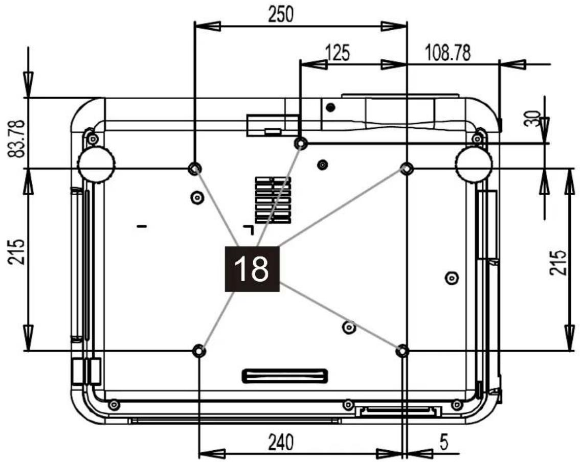
| 18. | Ceiling support holes | Contact your dealer for information on mounting the projector on a ceiling |
Note:
When installing, ensure that you use only UL Listed ceiling mounts.
Caution:
With ceiling installation, use approved mounting hardware & M4 screws; maximum depth of screw: 12 mm; distance from ceiling/ wall: 20 cm (0.7 feet) for proper ventilation; distance from fluorescent lamps: at least 1 m (3 feet) front and back of the projector. For permanent installations, follow local codes.
Top Features
OSD Controls and Status LEDs
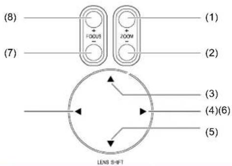

| ITEM LABEL | DESCRIPTION | |
| 1. | ZOOM+ | Increase/decrease projected image size |
| 2. | ZOOM- | |
| 3. | UP CURSOR | Move image left, right, up, or down |
| 4. | RIGHT CURSOR | |
| 5. | DOWN CURSOR | |
| 6. | LEFT CURSOR | |
| 7. | FOCUS- | Focus the projected image |
| 8. | FOCUS+ | |
| 9. | MENU Open / Close the OSD | |
| 10. | UP/ DOWN/ LEFT/ RIGHT BUTTONS | Navigate and change settings in the OSD |
| 11. | CANCEL Exit the On-Screen Display (OSD) | |
| 12. | AUTO Optimize image size, position, and resolution | |
| 13. | LAMP 2 (LED) | Green / Flashing, See Indicator Messages |
| 14. | LAMP 1 (LED) | |
| 15. | ENTER Select or change settings in the OSD | |
| 16. | POWER | Turn the projector on or off (main power switch must be turned on first).Press to place the projector in standby mode. |
| 17. | SOURCE Detects the input device | |
| 18. | POWER (LED) | Green / Orange / FlashingSee Indicator Messages |
| 19. | WARNING (LED) | Green / Red / Orange / FlashingSee Indicator Messages |
Terminal Panel Features
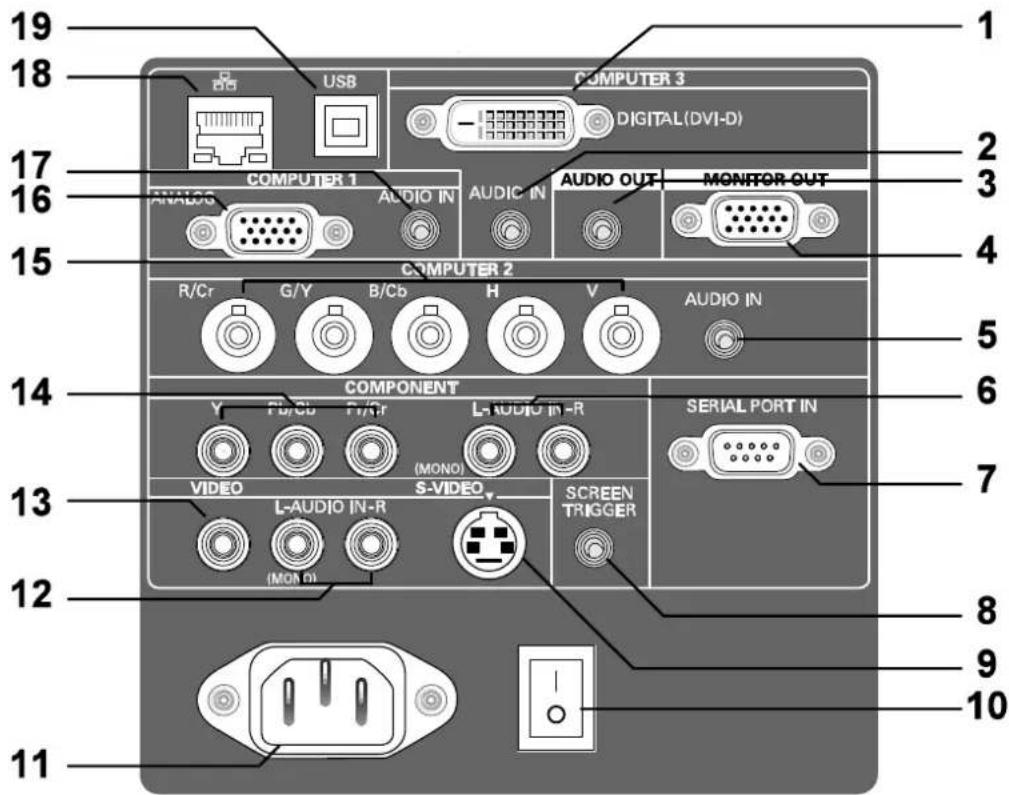
| ITEM LABEL DESCRIPTION | ||
| 1. | COMPUTER 3 IN Connect the DVI-D cable (not supplied) from a computer | |
| 2. | AUDIO IN (COMPUTER 3) | Connect the audio cable (not supplied) from the input device |
| 3. | AUDIO OUT Audio loop-thru | |
| 4. | MONITOR OUT Connect to a monitor | |
| 5. | AUDIO IN (COMPUTER 2) | Connect the audio cable (not supplied) from the input device |
| 6. | AUDIO IN [L (MONO)/R] (COMPONENT) | Connect an RCA audio cables (not supplied) from the input device right and left channels |
| 7. | SERIAL PORT IN Installation control | |
| 8. | SCREEN TRIGGER | When connected to the screen through a commercially available cable, the screen deploys automatically on start up of the projector. The screen retracts when the projector is powered off (see notes below) |
| 9. | S-VIDEO Connect a commercially available S-video cable from a video device | |
| 10. | POWER SWITCH Turn on/off the projector | |
| 11. | AC IN Connect the supplied power cable | |
| 12. | AUDIO IN [L (MONO)/R] (VIDEO) | Connect RCA audio cables (not supplied) from the input device right and left channels. This audio jack is shared with S-Video input. |
| 13. | VIDEO IN | Connect a composite video cable (not supplied) from a video device to the yellow RCA jack |
| 14. | COMPONENT IN (Y, Pb/Cb, Pr/Cr) | Connect a component video enabled device |
| 15. | COMPUTER 2 IN (R/Cr, G/Y, B/Cb, H, V) | Connect RGBHV or Component signal from computer or component video enabled device |
| 16. | COMPUTER 1 IN Connect a VGA cable (supplied) from a computer | |
| 17. | AUDIO IN (COMPUTER 1) | Connect the audio cable (not supplied) from the input device |
| 18. | LAN Connect a LAN cable (not supplied) from a computer | |
| 19. | SERVICE | Connect the USB cable (not supplied) from a computer. For service personnel only. |
Note:
- To use this feature, you must turn on the Screen Trigger function on the OSD.
- Screen controllers are supplied and supported by screen manufacturers.
- Do not use this jack for anything other than intended use.
Remote Control Parts

Important:
- Avoid using the projector with bright fluorescent lighting turned on. Certain high-frequency fluorescent lights can disrupt remote control operation.
- Be sure nothing obstructs the path between the remote control and the projector. If the path between the remote control and the projector is obstructed, you can bounce the signal off certain reflective surfaces such as projector screens.
- The buttons and keys on the projector have the same functions as the corresponding buttons on the remote control. This user's manual describes the functions based on the remote control.
| ITEM LABEL DESCRIPTION | ||
| 1. | Status LED Lights when the remote control is used | |
| 2. | Laser Use as on screen pointer. DO NOT POINT IN EYES. | |
| 3. | Up Up arrow when connected through USB to a PC | |
| 4. | Right Right arrow when connected through USB to a PC | |
| 5. | Down Down arrow when connected through USB to a PC | |
| 6. | Page Down Page down when connected through USB to a PC | |
| 7. | Up cursor Navigates and changes settings in the OSD | |
| 8. | Right cursor | Navigates and changes settings in the OSD |
| 9. | Down cursor | |
| 10. | Volume +/- Adjusts volume | |
| 11. | Mute Mutes the built-in speaker | |
| 12. | Zoom+ Zoom in | |
| 13. | Zoom- | Zoom out |
| 14. | Freeze Freeze/unfreezes the on-screen picture | |
| 15. | Blank Makes the screen blank | |
| 16. | Source Detects the input device | |
| 17. | Auto Auto adjustment for phase, tracking, size, position | |
| 18. | Menu Opens the OSD | |
| 19. | Status | Opens the OSD Status menu (the menu only opens when an input device is detected) |
| 20. | Keystone top/bottom Corrects image-trapezoid (wider top/bottom) effect | |
| 21. | Left cursor Navigates and changes settings in the OSD | |
| 22. | Enter Changes settings in the OSD | |
| 23. | Page Up Page up when connected through USB to a PC | |
| 24. | Left | Left arrow when connected through USB to a PC |
| 25. | Enter Enter key when connected through USB to a PC | |
| 26. | Power | Turns the projector on or off |
Note:
The remote control can only interface with a computer when connected to the computer through a USB cable connection. The computer cable connects a computer to the projector for display purposes only.
Remote Control Operating Range
The remote control uses infrared transmission to control the projector. It is not necessary to point the remote directly at the projector. Provided you are not holding the remote perpendicular to the sides or the rear of the projector, the remote will function well within a radius of about 7 meters (23 feet) and 15 degrees above or below the projector level. If the projector does not respond to the remote control, move a little closer.
Projector and Remote Control Buttons
The projector can be operated using the remote control or the buttons on the top of the projector. All operations can be carried out with the remote control; however, the buttons on the projector are limited in use. The following illustration shows the corresponding buttons on the remote control and on the projector.
Remote Control


Some buttons on the projector have two functions. For example, item 6/11 on the projector functions as both the volume down button and as the left cursor key in OSD menus.
Inserting the Remote Control Batteries
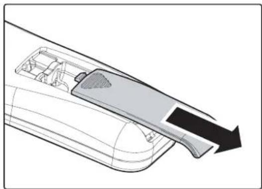
- Remove the battery compartment cover by sliding the cover in the direction of the arrow.
natural_image
Diagram of a device interior with a handle and arrow indicating direction (no text or symbols)- Insert the supplied batteries taking note of the polarity (+/-) as shown here.

natural_image
Diagram of a remote control casing with two batteries and arrows indicating rotation (no text or symbols)- Replace the cover.

natural_image
Technical line drawing of a mechanical component or assembly (no text or symbols visible)Caution:
- Only use AAA batteries. (Alkaline is better).
- Dispose of used batteries according to local ordinance regulations.
- Remove the battery when not using the projector for prolonged periods.
Installing or Removing the Optional Lens
Caution:
- Do not shake or place excessive pressure on the projector or the lens components as the projector and lens components contain precision parts.
- When shipping the projector with the optional lens, remove the optional lens before shipping the projector. The lens and the lens shift mechanism may encounter damage caused by improper handling during transportation.
- Before removing or installing the lens, be sure to turn off the projector, wait until the cooling fans stop, and turn off the main power switch.
- Do not touch the lens surface when removing or installing the lens.
- Keep fingerprints, dust or oil off the lens surface. Do not scratch the lens surface.
• Work on a level surface with a soft cloth under it to avoid scratching. - If you remove and store the lens, attach the lens cap to the projector to keep off dust and dirt.
Removing the Existing Lens From the Projector
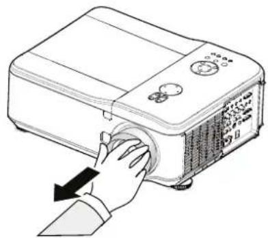
- Pull out the lens cap.
natural_image
Illustration of a projector with a hand pressing down on its side panel (no text or symbols visible)- Push the LENS RELEASE button all the way in and rotate the lens counterclockwise.
The existing lens will be disengaged.

natural_image
Illustration of a projector with hand operating its internal panel, showing motion arrows (no text or symbols)- Pull out the existing lens slowly.

natural_image
Illustration of a projector with a hand pressing down on it, showing no text or symbols.Caution:
When installing the lens into the projector, be sure to remove the lens cap from the back of the optional lens before installing the optional lens into the projector. Failure to do so will cause damage to the projector.
Installing the New Lens
- Pull out the existing lens slowly.

- Rotate the lens clockwise until it clicks into place.

natural_image
Illustration of a hand pressing down on a projector with a circular button, showing no text or symbols.Throw Distance and Screen Size
Example of GB940G:
The further your projector is from the screen or wall, the larger the image. The minimum size the image can be is approximately 40 inches (1 m) measured diagonally when the projector is roughly 71 inches (1.8 m) from the wall or screen. The largest the image can be is 500 inches (12.7 m) when the projector is about 915 inches (23.2 m) from the wall or screen.

| Screen Size GC805G GB942G GB940G | |||||||||||||||
| Diagonal W | dth Height | 0.77 1.33 - 1.79 1.78 - 2.35 | |||||||||||||
| Distance | |||||||||||||||
| [inches] | [m] | [inches] | [m] | [inches] | [m] | [inches] | [m] | [inches] | [m] | [inches] | [m] | ||||
| 40 | 1.02 | 34.3 | 0.87 | 20.5 | 0.52 | 45.4 - 61.8 | 1.15 - 1.57 | 60.9 - 81.0 | 1.55 | 2.06 | |||||
| 50 | 1.27 | 42.9 | 1.09 | 25.6 | 0.65 | 33.5 | 0.85 | 57.2 - 77.7 | 1.45 - 1.97 | 76.7 - 101.9 | 1.95 | 2.59 | |||
| 60 | 1.52 | 51.6 | 1.31 | 30.7 | 0.78 | 40.5 | 1.03 | 69.0 - 93.6 | 1.75 - 2.38 | 92.5 - 122.8 | 2.35 | 3.12 | |||
| 67 | 1.70 | 57.6 | 1.47 | 34.3 | 0.87 | 45.4 | 1.15 | 77.3 - 104.7 | 1.96 - 2.66 | 103.6 - 137.4 | 2.63 | 3.49 | |||
| 72 | 1.83 | 61.9 | 1.58 | 36.8 | 0.94 | 48.9 | 1.24 | 83.2 - 112.7 | 2.11 - 2.86 | 111.5 - 147.9 | 2.83 | 3.76 | |||
| 80 | 2.03 | 68.5 | 1.74 | 41.3 | 1.05 | 54.5 | 1.38 | 92.7 - 125.4 | 2.35 - 3.19 | 124.2 - 164.6 | 3.15 | 4.18 | |||
| 84 | 2.13 | 71.9 | 1.83 | 43.4 | 1.10 | 57.3 | 1.46 | 97.4 - 131.8 | 2.47 - 3.35 | 130.5 - 172.9 | 3.31 | 4.39 | |||
| 90 | 2.29 | 77.1 | 1.96 | 46.5 | 1.18 | 61.5 | 1.56 | 104.5 - 141.3 | 2.65 - 3.59 | 140.0 - 185.4 | 3.56 | 4.71 | |||
| 100 | 2.54 | 85.8 | 2.18 | 51.6 | 1.31 | 68.5 | 1.74 | 116.3 - 157.2 | 2.95 - 3.99 | 155.8 - 206.3 | 3.96 | 5.24 | |||
| 120 | 3.05 | 102.8 | 2.61 | 61.8 | 1.57 | 82.5 | 2.10 | 140.0 - 189.0 | 3.56 - 4.80 | 187.4 - 248.1 | 4.76 | 6.30 | |||
| 150 | 3.81 | 128.7 | 3.27 | 77.2 | 1.96 | 103.5 | 2.63 | 175.5 - 236.7 | 4.46 - 6.01 | 234.9 - 310.7 | 5.97 | 7.89 | |||
| 180 | 4.57 | 154.3 | 3.92 | 92.5 | 2.35 | 124.5 | 3.16 | 211.0 - 284.4 | 5.36 - 7.22 | 282.3 - 373.3 | 7.17 | 9.48 | |||
| 200 | 5.08 | 171.7 | 4.36 | 102.8 | 2.61 | 138.5 | 3.52 | 234.6 - 316.2 | 5.96 - 8.03 | 313.9 - 415.1 | 7.97 | 10.54 | |||
| 210 | 5.33 | 180.3 | 4.57 | 107.9 | 2.74 | 246.4 - 332.1 | 6.26 - 8.44 | 329.7 - 436.0 | 8.38 | 11.07 | |||||
| 240 | 6.10 | 206.0 | 5.24 | 123.4 | 3.13 | 281.9 - 379.8 | 7.16 - 9.65 | 377.2 - 498.6 | 9.58 | 12.66 | |||||
| 261 | 6.63 | 224.1 | 5.69 | 134.2 | 3.41 | 306.8 - 413.2 | 7.79 - 10.50 | 410.4 - 542.4 | 10.42 | 13.78 | |||||
| 270 | 6.86 | 231.8 | 5.89 | 138.8 | 3.52 | 317.4 - 427.5 | 8.06 - 10.86 | 424.6 - 561.2 | 10.79 | 14.25 | |||||
| 300 | 7.62 | 257.1 | 6.53 | 154.3 | 3.92 | 352.9 - 475.2 | 8.96 - 12.07 | 472.1 - 623.8 | 11.99 | 15.85 | |||||
| 350 | 8.89 | 300.0 | 7.62 | 180.0 | 4.57 | 412.0 - 554.8 | 10.47 - 14.09 | 551.2 - 728.2 | 14.00 | 18.50 | |||||
| 400 | 10.16 | 342.9 | 8.71 | 205.9 | 5.23 | 471.2 - 634.3 | 11.97 - 16.11 | 630.2 - 832.6 | 16.01 | 21.15 | |||||
| 450 | 11.43 | 385.8 | 9.80 | 231.6 | 5.88 | 530.3 - 713.8 | 13.47 - 18.13 | 709.3 - 937.0 | 18.02 | 23.80 | |||||
| 500 | 12.70 | 428.7 | 10.89 | 257.1 | 6.53 | 589.5 - 793.3 | 14.97 - 20.15 | 788.4 - 1041.4 | 20.02 | 26.45 | |||||
| Screen Size GB949G GB957/G | ||||||||||
| Diagonal Width Height | 2.22 - 4.43 4.43 - 8.8 | |||||||||
| Distance | ||||||||||
| [inches] | [m] | [inches] | [m] | [inches] | [m] | [inches] | [m] | [inches] | [m] | |
| 40 | 1.02 | 34.3 | 0.87 | 20.5 | 0.52 | 75.7 - | 155.0 | 1.92 - 3.94 | 151.7 - 289.8 | 3.85 - 7.36 |
| 50 | 1.27 | 42.9 | 1.09 | 25.6 | 0.65 | 95.7 - | 194.7 | 2.43 - 4.95 | 190.9 - 363.5 | 4.85 - 9.23 |
| 60 | 1.52 | 51.6 | 1.31 | 30.7 | 0.78 | 115.6 - | 234.5 | 2.94 - 5.96 | 230.2 - 437.3 | 5.85 - 11.11 |
| 67 | 1.70 | 57.6 | 1.47 | 34.3 | 0.87 | 129.6 - | 262.4 | 3.29 - 6.66 | 257.7 - 488.9 | 6.55 - 12.42 |
| 72 | 1.83 | 61.9 | 1.58 | 36.8 | 0.94 | 139.6 - | 282.3 | 3.55 - 7.17 | 277.3 - 525.8 | 7.04 - 13.36 |
| 80 | 2.03 | 68.5 | 1.74 | 41.3 | 1.05 | 155.6 - | 314.1 | 3.95 - 7.98 | 308.8 - 584.9 | 7.84 - 14.86 |
| 84 | 2.13 | 71.9 | 1.83 | 43.4 | 1.10 | 163.6 - | 330.0 | 4.15 - 8.38 | 324.5 - 614.4 | 8.24 - 15.60 |
| 90 | 2.29 | 77.1 | 1.96 | 46.5 | 1.18 | 175.5 - | 353.9 | 4.46 - 8.99 | 348.0 - 658.6 | 8.84 - 16.73 |
| 100 | 2.54 | 85.8 | 2.18 | 51.6 | 1.31 | 195.5 - | 393.6 | 4.97 - 10.00 | 387.3 - 732.4 | 9.84 - 18.60 |
| 120 | 3.05 | 102.8 | 2.61 | 61.8 | 1.57 | 235.4 - | 473.2 | 5.98 - 12.02 | 465.9 - 880.0 | 11.83 - 22.35 |
| 150 | 3.81 | 128.7 | 3.27 | 77.2 | 1.96 | 295.3 - | 592.6 | 7.50 - 15.05 | 583.7 - 1101.3 | 14.83 - 27.97 |
| 180 | 4.57 | 154.3 | 3.92 | 92.5 | 2.35 | 355.2 - | 711.9 | 9.02 - 18.08 | 701.5 - 1322.6 | 17.82 - 33.59 |
| 200 | 5.08 | 171.7 | 4.36 | 102.8 | 2.61 | 395.2 - | 791.5 | 10.04 - 20.10 | 780.0 - 1470.2 | 19.81 - 37.34 |
| 210 | 5.33 | 180.3 | 4.57 | 107.9 | 2.74 | 415.1 - | 831.3 | 10.54 - 21.11 | 819.3 - 1543.9 | 20.81 - 39.22 |
| 240 | 6.10 | 206.0 | 5.24 | 123.4 | 3.13 | 475.0 - | 950.6 | 12.07 - 24.15 | 937.1 - 1765.3 | 23.80 - 44.84 |
| 261 | 6.63 | 224.1 | 5.69 | 134.2 | 3.41 | 517.0 - | 1034.1 | 13.13 - 26.27 | 1019.6 - 1920.2 | 25.90 - 48.77 |
| 270 | 6.86 | 231.8 | 5.89 | 138.8 | 3.52 | 534.9 - | 1069.9 | 13.59 - 27.18 | 1054.9 - 1986.6 | 26.80 - 50.46 |
| 300 | 7.62 | 257.1 | 6.53 | 154.3 | 3.92 | 594.8 - 1189.3 | 15.11 - 30.21 | 1172.6 - 2207.9 | 29.79 - 56.08 | |
| 350 | 8.89 | 300.0 | 7.62 | 180.0 | 4.57 | 694.7 - 1388.2 | 17.64 - 35.26 | 1369.1 - 2576.8 | 34.78 - 65.45 | |
| 400 | 10.16 | 342.9 | 8.71 | 205.9 | 5.23 | 794.5 - | 1587.1 | 20.18 - 40.31 | 1565.5 - 2945.7 | 39.76 - 74.82 |
| 450 | 11.43 | 385.8 | 9.80 | 231.6 | 5.88 | 894.3 - | 1786.0 | 22.72 - 45.37 | 1761.9 - 3314.6 | 44.75 - 84.19 |
| 500 | 12.70 | 428.7 | 10.89 | 257.1 | 6.53 | 994.1 - | 1984.9 | 25.25 - 50.42 | 1958.2 - 3683.4 | 49.74 - 93.56 |
Caution:
- Ceiling installation must be done by a qualified professional. Contact your dealer for more information. It is not recommended you install the projector yourself.
- Only use the projector on a solid, level surface. Serious injury and damage can occur if the projector is dropped.
- Do not use the projector in an environment where extreme temperature occurs. The projector must be used at temperatures between 41 degrees Fahrenheit (5 degrees Celsius) and 104 degrees Fahrenheit (40 degrees Celsius).
- Screen damage will occur if the projector is exposed to moisture, dust or smoke.
- Do not cover the vents on the projector. Proper ventilation is required to dissipate heat. Damage to the projector will occur if the vents are covered.
Installing the Optional Color Wheel
The projector comes with a four-segment color wheel installed. An additional six-segment color wheel is optional. To replace the color wheel (located under the lamp cover adjacent to lamp 1) refer to the following guide.
Note:
Wait until the lamp house and the color wheel cool off.
-
Remove the four screws (A) on the lamp cover.
-
Lift the lamp cover in the direction of the arrow (B).
-
Unscrew the retaining screws (x 4) on the four-segment color wheel.
-
Lift the color wheel in the direction shown.

-
Insert the six-segment color wheel
-
Close the lamp cover and secure the retaining screws as shown.
-
Align the lamp cover in the direction of the arrow (B) and slide it into place.
Secure the captive screw (A).

Storing Unused Color Wheel:
Keep the unused color wheel in the zipper bag in which the 6-segment color wheel (not supplied) was packaged. This bag prevents dust from falling or collecting on the color wheel.
Making Connections
Connecting Your PC or Macintosh Computer
Enabling the computer's external display:
Displaying an image on the notebook PC's screen does not necessarily mean it outputs a signal to the projector. When using a PC compatible laptop, a combination of function keys will enable/disable the external display. Usually, the combination of the Fn-key along with one of the 12 function keys activates the external display.
To connect a PC or Macintosh computer to the projector, refer to the following guide.
- Connect a computer to the projector through one of the three available input data connections before turning on the PC or the projector. The best signal order (from best to least suitable) is as follows:
- Computer 3 in (see Terminal Panel Features on page 5) is a digital signal and offers the best connection to your computer.
Note:
The DVI (DIGITAL) connector (COMPUTER 3) accepts VGA (640 x 480), 1152 x 864, XGA (1024 x 768), SXGA (1280 x 1024@up to 60Hz) and UXGA(1600 x 1200 @ 60Hz).
- Computer 2 in (see Terminal Panel Features on page 5) is an analog signal; use a DSUB-15 cable-to-5BNC connection.
- Computer 1 in as shown below (see Terminal Panel Features on page 5) is an analog signal that uses a standard RGB computer cable.

- Turn on the projector and select the chosen method of connection from the source menu before turning on the PC (see Selecting an Input Source on page 23).
- Turn on the PC.
Note:
Failure to follow the above steps may not activate the digital output of the graphics card resulting in no picture being displayed. Should this happen, restart your PC.
Connecting an External Monitor
Connect an external monitor to the projector through RGB out connections as shown below (see Terminal Panel Features on page 5).

Connecting Your DVD Player with Component Output
To connect a DVD Player to the projector, refer to the following guide.
- Connect the DVD Player to the projector as shown below before turning on the Player or the projector.

flowchart
graph TD
    A["Monitor"] --> B["Audio Out"]
    A --> C["Component"]
    A --> D["L"]
    A --> E["R"]
    A --> F["Audio In L R"]
    B --> G["Component Y"]
    B --> H["Cb Cr"]
    B --> I["L R"]
-
Turn on the projector and select Component from the source menu before turning on the DVD Player (see Selecting an Input Source on page 23).
-
Turn on the DVD Player.
Note:
Refer to your DVD player's user's manual for more information about your DVD player's video output requirements.
Connecting Your VCR or Laser Disc Player
To connect your VCR or Laser Disc Player, refer to the following diagram.
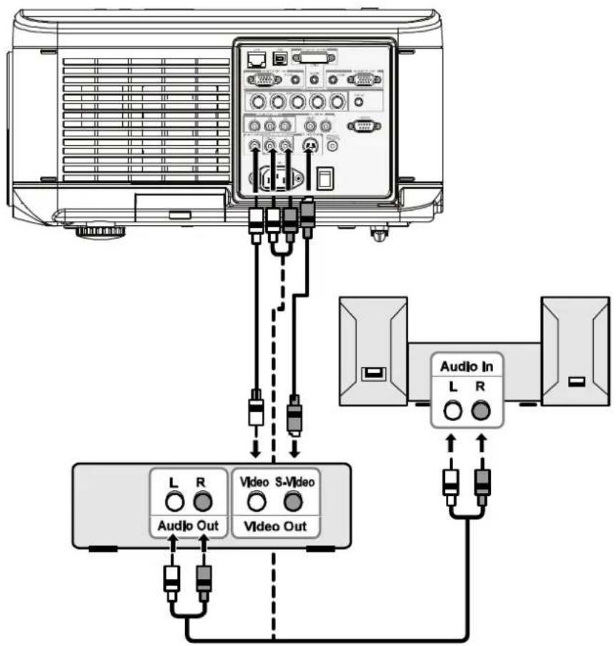
Note:
- Refer to your VCR or laser disc player user's manual for more information about your device's requirements.
- Images may not be displayed correctly when using an S-Video or Video connection to fast-forward or fast-rewind scanning.
The AUDIO IN RCA jack is shared between VIDEO IN and S-VIDEO IN.
PROJECTING AN IMAGE (BASIC OPERATION)
Turning on the Projector
Once the projector is correctly located and the power cable and other connections are in place, it is important that the projector is powered on correctly in order to avoid damage to components and unnecessary wear and tear. Refer to the following guide to power on the projector.
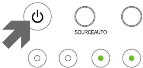
- Connect the power cable (A). Press the main power switch to the on (I) position as shown (B). All four LEDs light orange, then the Lamp1 and 2 LEDs turn off and the Warning LED lights green.
- Press the POWER button once (see OSD Controls and Status LEDs on page 4). The Power LED flashes green and the internal cooling fan starts.
- After approximately 10 seconds, the Lamp1 and Lamp2 LEDs light green and the Power LED flashes more rapidly.


POWERWARNINGLAMP1LAMP2
- Once the power LED is lit a solid green, the projector is ready for use.
Note: If any of the LEDs remain flashing or blink there may be a problem with the startup. Please refer to the Troubleshooting section on page 84.
Note on Startup Screen (Menu Language Select screen)
In the first instance of powering on the projector, the language menu is displayed to select the default language.
Please select a menu language.
| Please select a menu language. | English |
| Wählen Sie bitte die Menü Sprache aus. | Deutsch |
| S'il vous plaît choisir la langue de menu. | Français |
| Per favore scegliere la lingua del menu. | Italiano |
| Escoja por favor el idioma de menú. | Español |
| Välj menyn språken. | Svenska |
| メニュー言語を選択してください。 | 日本語 |
| 请选择菜单语言。 | 簡体中文 |
| 請選擇選單語言。 | 繁體中文 |
Select "UP", "DOWN" & "SELECT"
Select the required default language using the ▲ or ▼ buttons on the OSD menu panel or the remote control unit and press ←.
Note:
The language select screen only appears on the first instance of power on. All subsequent operations assume the selected default language. To change the default see page 61.
Selecting an Input Source
The Input Source can be selected from the projector's control panel or from the remote control unit. Refer to the following guide to select the Input Source.
- Press Menu on the OSD control panel or on the remote control unit to display the Main Menu. Scroll to the Input menu using ▲or▼ and press ←.
Note: Return to the projected image by pressing Cancel twice.

- Select the required source using ▲ or ▼ and press ←.
Computer1
○ Computer2
○ Computer3
○ Component
○ Video
○ S-Video
Adjusting the Picture Position and Picture Size
The Picture Position and Picture Size can be adjusted manually from the lens control panel or from the remote control unit. Refer to the following guides to adjust Picture Position manually.
Adjusting Picture Position Manually
- Press the Lens Shift keypad on the projector in any direction to bring up the Lens Shift window.
- Press the directional key as required to shift the image. Releasing the directional arrow will re-center the cursor.
- To alter the picture size, press Menu and select the Adjust menu using ▲ or ▼. Press ← to open the Adjust menu. Press ◀ or ▶ to select Image Options followed by ▲ or ▼ to select Screen. Press ←.


natural_image
Diagram showing a device with an arrow pointing to a screen, no text or symbols present
- The Screen window is displayed. Select the desired picture size using ▲ or ▼ and press ←.

- When finished, press Cancel to return to the projected image.
Lens Shift Adjustable Range
The adjustable range for lens shift is tabulated below and subject to the conditions listed.
Note:
The drawings below apply to the standard lens (GB940G) only.

From the Remote Control Unit
- Press Menu and select the Setting menu using ▲or▼. Press ← to open the Setting menu. Press ◀or▶ to select Basic followed by ▲or▼ to select Lens Shift. Press ←.

- The Lens Shift window displays.
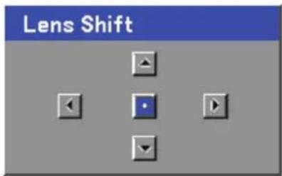
- Press the directional buttons as required to shift the image. Re-leasing the directional arrow will re-center the cursor.

natural_image
Diagram showing a device with an arrow pointing to a screen, no text or symbols present- To alter the picture size, press Menu and select the Adjust menu using ▲ or ▼. Press ← to open the Adjust menu. Press ← or▶ to select Image Options followed by ▲ or ▼ to select Screen. Press ←.
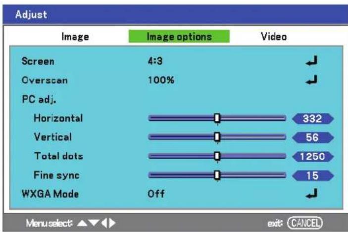
- Select the desired picture size using ▲ or ▼ and press ←.
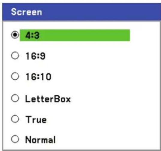
- When finished, press Menu to return to the projected image.
Adjusting the Projector Level
-
To raise the level of the projector, twist the adjusters clockwise.
-
To lower the level of the projector, lift the projector and twist the adjusters counter clockwise.

natural_image
Line drawing of a projector with circular buttons and a slide, showing rotational control arrows (no text or symbols)
natural_image
Line drawing of a projector with control knobs and wheels, showing internal components and rotation arrows (no text or symbols)Optimizing an RGB Image Automatically
Adjusting the Image Using AUTO
To optimize an RGB image automatically refer to the following guide.
Press the Auto button on the remote control (see Remote Control Parts on page 7) or the AUTO button on the OSD control panel to optimize an RGB image automatically.
This adjustment may be necessary when you connect your computer for the first time.

flowchart
graph TD
    A["Object"] --> B["Target Box"]
    B --> C["ABC"]
    style A fill:#f9f,stroke:#333
    style C fill:#bbf,stroke:#333
Adjusting Volume Up and Down
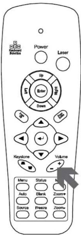
The volume can be adjusted from the OSD Control Panel or with the Remote Control unit. Refer to the following as a guide.
- Press the Volume +/- buttons on the remote control or the ◀▶ buttons on the OSD control panel. The volume level is displayed on screen.
- Use the Volume +/- buttons or the ◀▶ buttons on the OSD control panel to adjust the level.


Turning off the Projector
Once the projector is no longer required, it is important to shut it down correctly to avoid damage or unnecessary wear and tear to the projector.
Note:
- Do not unplug the power cable from the wall outlet or projector when the projector is powered on. Doing so can cause damage to the AC IN connector of the projector and (or) the prong plug of the power cable. To turn off the AC power supply when the projector is powered on, use a power strip equipped with a switch and a breaker.
- Do not turn off the AC power supply within 10 seconds of making adjustment or setting changes and closing the menu. Doing so can cause loss of adjustments and settings and return to default.
Refer to the following guide to shut down the projector.
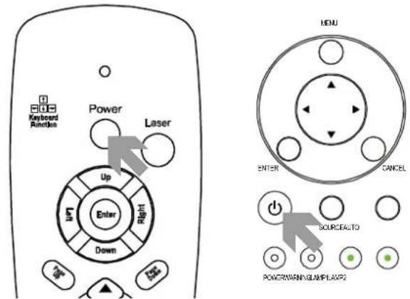
- Press the POWER button once. The Power Off window displays.
- Press the POWER button or again on the OSD control panel or remote control to verify power off. The cooling fans continue to operate (cooling-off time) and the power LED flashes orange. The cooling fans stop operating when the projector turns off.
- The projector enters Standby mode when the power LED lights orange and the warning LED lights green.
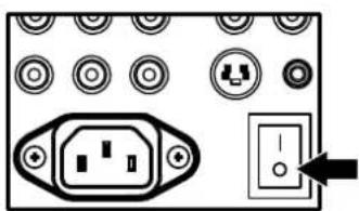
- Press the Main Power switch to the off position (O) to turn off the projector.

Please wait a moment.
natural_image
Electrical connector panel with socket, power outlet, and switch (no text or symbols)About Direct Power Off
The projector has a feature called "Direct Power Off". This feature allows the projector to be turned off (even when projecting an image) using a power strip equipped with a switch and a breaker.
Note:
Before using Direct Power Off, be sure to allow at least 20 minutes immediately after turning on the projector and starting to display an image.
After Use
Preparation: Make sure that the projector is turned off.
- Unplug the power cable.
- Disconnect any other cables.
- Return the height adjusters to their original, minimum position.
- Cover the lens with the lens cap.
Turning Off the Image and Sound
The projected image and sound can be turned off for short periods of time with the remote control. This feature is useful for breaking up presentations or for other brief interruptions in projections. To turn off the picture and image, refer to the following guide.
- Press the Blank button on the remote control once (see Remote Control Parts on page 7).
- The image does not display.
- To resume projection, press the Blank button once more.
Note:
For extended periods of time it is recommended that the projector be powered off.
Freezing a Picture
The projected image can be frozen for short periods of time by using the remote control. This feature is useful for capturing still images from movies or freezing an animation at a particular point. To freeze the projected image, refer to the following guide.
- Press the Freeze button on the remote control once (see Remote Control Parts on page 7).
- The screen freezes.
- To resume, press the Freeze button once more.
Note:
For extended periods of time it is recommended that the projector be powered off.
Adjusting the Focus/Zoom Manually
The focus and zoom can be adjusted manually from the projector focus/zoom panel. Refer to the following guides to adjust the focus and zoom manually.
Adjusting by Using the OSD Control Panel
- Press the Focus or Zoom button on the projector panel to display the appropriate window.

- Adjust the Focus/Zoom using the increase and decrease buttons as required.


- Press Cancel to return to the projected image.

Changing Lamp Mode
The projector has two lamp modes available, Normal and Eco. The Normal mode is used for everyday standard projection, whereas the Eco mode is used for saving power and lamp life. To change the Lamp Mode, refer to the following guides.
Changing Lamp Mode by Using the Projector's OSD Control Panel
- Press Menu on the projector's OSD control panel to display the Main menu. Scroll to the Setting menu using ▲ or ▼ and press ←.

- Select the Basic tab using ◀or▶ and select Lamp control using ▲or▼. Press ←.

- From the Lamp control window, select Normal or Eco using ▲or▼. Select OK and press ←.

Note:
When the projector is in Eco mode, brightness may be affected.
Normal Mode: 100% Brightness
Eco Mode: approx. 85% Brightness
Getting Information
The Information screen provides details on the life of consumable items within the projector as well as other information such as software version. To access the Information screen, refer to the following guide.
- Press Menu on the projector's OSD control panel or remote control to display the Main Menu. Scroll to the Information menu using ▲or▼ and press ←.

- The Usage time menu is displayed as the default view. The menu items in this screen are for display and cannot be modified.
![Information Usage time Input Network Version Lamp1 life remaining 50% Lamp2 life remaining 50% Lamp1 time 1000[H] Lamp2 time 1000[H] PJ time 1000[H] Filter time 1000[H] Menu select: exit: CANCEL](/content/2026/05/1054913/images/60817fc709ea51bd9e3995ae57556a0e1dea96babab6cff9585860f6624c2890.jpg)
- Press Cancel or Menu to return to the projected image.
Adjusting Position/Total Dots/Fine Sync
The Position/Total dots/Fine sync and Keystone Correction can be adjusted manually from the projector's control panel or from the remote control unit. Refer to the following guides to adjust the Keystone Distortion manually.
Adjusting Position/Total Dots/Fine Sync by using the OSD Control Panel
1.
Press the Menu button to display the Main menu. Select the Adjust menu using ▲ or ▼ and press ← to display the Adjust menu.

2.
From the Adjust menu, press ◀or▶ to select Image Options and scroll using ▲or▼ to Horizontal, Vertical, Total dots, or Fine sync.

3.
Adjust the Horizontal, Vertical, Total dots, or Fine sync sliding bars using the select ▲▼◀▶ buttons.
4.
Press Cancel or Menu to return to the projected image.
Correcting Keystone by Using the Remote Control
Important:
When adjusting the keystone, place the projector in the following position.
• Horizontal: set to the lens center
• Vertical: set to the maximum top
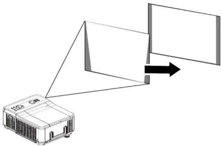
- Press the Keystone button to display the Keystone window.
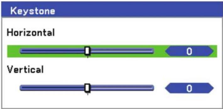
- Adjust the Horizontal and Vertical sliding bars using the select ▲▼◀▶ buttons.
- Adjust the slide bars until the screen trapezoid is a regular shape (see diagram).
natural_image
Diagram showing a device emitting light rays from a screen to a rectangular panel, with no visible text or symbols.- Press Cancel or Menu to return to the projected image.
Note:
Holding down the Keystone button for 2 seconds resets the default keystone values.
| ADJUSTMENT HORIZONTAL VERTICAL | ||
| Keystone Max. +/- 35° approx. | Max. +/- 40° approx. | |
The following are conditions under which the maximum angle is achieved:
- When the standard lens (GB940G) is used
- When the lens shift is set to H for center and V for 0.5 shift.
- When the lens shift is used and yet you do not get the above-mentioned condition (H for center and V for 0.5 shift), you cannot adjust the lens shift correctly.
■ Image is projected in Wide mode
■ Resolution is WXGA
Note: Higher resolution than WXGA narrows the adjustable range.
Menu items should be set as follows:
■ Aspect Ratio ..... 16:10
Horizontal and Vertical are adjusted separately.
A combination of both adjustments narrows the adjustable range.
Preventing the Unauthorized Use of the Projector
The projector has a built-in security feature to lock the OSD control panels and deny remote control operation. The security feature has no default keyword; in the first instance of enabling the security feature, the user must define a keyword.
Locking the Projector
To setup the security keyword, refer to the following guide.
1.
Press Menu on the OSD control panel on the projector or remote control to display the Main menu. Scroll to the Setting menu using ▲ or ▼ and press ←.

2.
The Setting menu is displayed. Select the Installation tab using ◀or►.

3.
Select PIN code lock using ▲or▼. Press ←. You are prompted to enable the PIN code lock function. Select On using ▲or▼. Select OK and press ←.

- The PIN code window is displayed. Enter a PIN code between 4 and 10 characters using ▲▼◀▶. The PIN code characters change to “*”. Press ←.
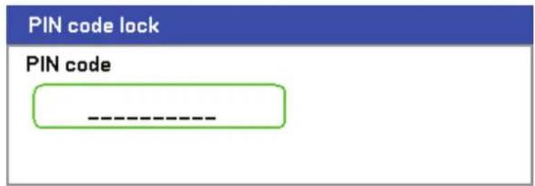
- Once a successful PIN code is entered, a confirmation screen is displayed. Enter the same password as the previous step and write it down for later reference. Press ←. A security activation message is displayed. Select Cancel or Menu to return to the Setting menu or select OK to enable security.

Caution: When you have set or changed the PIN code, take a memo and keep it securely. If you forget your PIN code, the projector can no longer be started. Contact your dealer or the service center.
Unlocking the Projector
To unlock the projector, refer to the following guide.
- When the projector is locked, either by request during operation or at start up, the locked message is displayed.
Projector is locked! Enter your PIN code.
- To unlock the projector, press Menu on the control panel or remote control. The PIN code window is displayed. Enter the previously defined PIN code to activate the projector.

Using the Physical Lock
Using the Kensington Lock
If you are concerned about security, attach the projector to a permanent object with the Kensington slot and a security cable.

natural_image
Technical line drawing of a vehicle air conditioner unit with a speech bubble containing a lock icon (no text or symbols on the diagram itself)Using the Menus
The projector has an On-Screen Display (OSD) that lets you make image adjustments and change various settings.
Navigating the OSD
You can use the remote control or the buttons on the top of the projector to navigate and make changes to the OSD. The following illustration shows the corresponding buttons on the remote control and on the projector.


- To open the OSD, press the Menu button on the OSD control panel or remote control. There are six initial menus. Press the cursor ▲ or ▼ buttons to move through the initial menus and ← to enter the desired menu.

- Press the cursor ◀ or ▶ button to move through secondary menus.

- Press ▲ or ▼ to select menu items and ◀ or ▶ to change values for settings. Press ← to confirm the new setting.

- Press Cancel or Menu to close the OSD or leave a submenu.
Menu Tree
Use the following illustrations to quickly find a setting or determine the range for a setting.

flowchart
graph TD
    A["Main/Input"] --> B["Computer 1"]
    A --> C["Computer2"]
    A --> D["Computer3"]
    A --> E["Component"]
    A --> F["Video"]
    A --> G["S-Video"]

    H["Main/Adjust"] --> I["Image"]
    I --> J["Image select"]
    J --> K["High-Bright"]
    J --> L["Presentation"]
    J --> M["Video"]
    J --> N["Movie"]
    J --> O["Graphic"]
    J --> P["iRGB"]

    H --> Q["Detail settings"]
    Q --> R["Contrast"]
    R --> S["0~100"]
    Q --> T["Brightness"]
    T --> U["0~100"]
    Q --> V["Sharpness"]
    V --> W["0~100"]
    Q --> X["Color"]
    X --> Y["0~31"]
    Q --> Z["Tint"]
    Z --> AA["Reset"]

    H --> AB["Image options"]
    AB --> AC["Screen"]
    AC --> AD["4:3"]
    AC --> AE["16:9"]
    AC --> AF["Side cut"]
    AC --> AG["True"]
    AC --> AH["Normal"]
    AC --> AI["Overscan"]
    AI --> AJ["0%/5%/10%/15%"]
    AI --> AK["PC adj"]
    AK --> AL["±50"]
    AK --> AM["Horizontal"]
    AM --> AN["±25"]
    AK --> AO["Vertical"]
    AO --> AP["±50"]
    AK --> AQ["Total dot"]
    AQ --> AR["±50"]
    AK --> AS["Fine sync"]
    AS --> AT["0~63"]

    H --> AU["Basic"]
    AU --> AV["Gamma"]
    AV --> AW["Dynamic/Natural/Black Detail"]
    AV --> AX["Color temp."]
    AX --> AY["5000K/6500K/7800K/8500K/9300K/10500K"]
    AV --> AZ["BrilliantColor"]
    AZ --> BA["1~3"]

    H --> BB["White balance"]
    BB --> BC["Red"]
    BC --> BD["0~100"]
    BC --> BE["Green"]
    BE --> BF["0~100"]
    BC --> BG["Blue"]
    BG --> BH["0~100"]
    BC --> BI["Contrast R"]
    BI --> BJ["0~100"]
    BC --> BK["Contrast G"]
    BK --> BL["0~100"]
    BC --> BM["Contrast B"]
    BM --> BN["0~100"]

    H --> BO["Color correction"]
    BO --> BP["Red"]
    BP --> BQ["-60~60"]
    BO --> BR["Green"]
    BR --> BS["-60~60"]
    BO --> BT["Blue"]
    BT --> BU["-60~60"]
    BO --> BV["Yellow"]
    BV --> BW["-60~60"]
    BO --> BX["Magenta"]
    BX --> BY["-60~60"]
    BO --> BZ["Cyan"]
        BZ --> CA["-60~60"]

    H --> CB["Video"]
    CB --> CC["Noise reduction"]
    CC --> DD["Off/Low/Mid/High"]
    CC --> DE["3D Y/C separation"]
    DE --> DF["ON/OFF"]

    H --> DG["Progressive"]
    DG --> DH["Off/Still/Normal/Movie"]

    H --> DI["Color matrix"]
    DI --> DJ["Auto/RGB/SDTV/HDTV"]

    H --> DK["Film"]
    DK --> DL["Off/2-2/2-3 Auto/2-2 On/2-3 On"]

flowchart
graph TD
    A["Main/Volumes"] --> B["0-61"]
    A --> C["Main/Setting"]
    C --> D["Basic"]
    C --> E["Installation"]
    D --> F["Ceiling & Rear"]
    D --> G["Display time"]
    D --> H["Background"]
    D --> I["P/N code lock"]
    D --> J["Key lock"]
    D --> K["DynamicBlack"]
    D --> L["RC sensor"]
    E --> M["Desktop front/Ceiling rear/Desktop rear/Ceiling front"]
    E --> N["Communication speed"]
    E --> O["Manual/Auto 5 sec/Auto 15 sec/Auto 45 sec"]
    E --> P["Blue/Black/Logo"]
    E --> Q["Off/On"]
    E --> R["Off/On"]
    E --> S["Both/Front/Back"]
    F --> T["Network setting"]
    G --> U["Network setting"]
    H --> V["Network setting"]
    I --> W["Network setting"]
    J --> X["Network setting"]
    K --> Y["Network setting"]
    L --> Z["Network setting"]
    M --> AA["Network setting"]
    N --> AB["Network setting"]
    O --> AC["Network setting"]
    P --> AD["Network setting"]
    Q --> AE["Network setting"]
    R --> AF["Network setting"]
    S --> AG["Network setting"]
    T --> AH["DHCP"]
    T --> AI["Enable/Disable"]
    U --> AJ["IP address"]
    U --> AK["Sabnet"]
    U --> AL["Gateway"]
    U --> AM["DNS"]
    U --> AN["Apply settings"]
    V --> AO["Enable/Disable"]
    W --> AP["Enable/Disable"]
    X --> AQ["Enable/Disable"]
    Y --> AR["Enable/Disable"]
    Z --> AS["Normal/Power saving"]
    AA --> AT["PC control"]
    AB --> AU["PC control/Network"]
    AC --> AV["PC control/Network"]
    AD --> AW["PC control/Network"]
    AE --> AX["PC control/Network"]
    AF --> AY["PC control/Network"]
    AG --> AZ["PC control/Network"]
    AH --> BA["Fower management"]
    AH --> BB["Screen trigger"]
    AH --> BC["Fan control"]
    AH --> BD["Default input select"]
    AH --> BE["Color system"]
    AH --> BF["Video"]
    AH --> BG["Video"]
    AH --> BH["S-Video"]
    AH --> BI["Message"]
    AH --> BJ["Filter warning"]
    AH --> BK["Search mode"]
    AI --> BL["Lamp control"]
    AI --> BM["Lamp mode"]
    AI --> BN["Lamp interval"]
    AI --> BO["Language"]
    AJ --> BP["Lens shift"]
    AJ --> BQ["Zoam"]
    AJ --> BR["Pocus"]

    C --> BS["Keystone"]
    BS --> BT["Horizontal"]
    BS --> BU["Vertical"]

    C --> BV["Man/Reset"]

    A --> BW["Usage time"]
    A --> BX["Input name"]

    A --> BY["Input signal"]

    A --> CA["Network"]

    A --> CB["Version"]

    B --> CC["Lamp1 life remaining"]
    B --> DD["Lamp2 life remaining"]
    B --> DE["Lamp3 time"]
    B --> DF["Lamp4 time"]
    B --> DG["PJ time"]
    B --> DH["Filter time"]

    CA --> DI["Input name: Signal"]

    CA --> DJ["H-Sync freq."]

    CA --> DK["V-Sync freq."]

    CA --> DL["Video type: Sync type"]

    CA --> DJ

    CA --> DK

    CA --> DL

    CA --> DM["Scan type: Sync polarity"]

    CA --> DN["Network: IP address, Subnet, Gateway, MAC address"]

    CA --> DO["Version: Model name, Firmware"]

    B <--> BE
Menu Elements
Some menus and windows contain large amounts of information in a small area. Refer to the following guide to navigate through options more easily.

Menu windows or dialog windows typically contain the following elements:
| ITEM LABEL DESCRIPTION | ||
| 1. | Title Indicates the menu title. | |
| 2. | Highlight | Indicates the selected menu or item. |
| 3. | Radio button Click this round button to select an option in a dialog box. | |
| 4. | Slide bar Indicates a representation of adjustable values. | |
| 5. | Exit Return to the previous menu. | |
Input Menu Descriptions and Functions
The Input menu displays all supported image sources.
Computer1
○ Computer2
○ Computer3
○ Component
○ Video
○ S-Video
Select the required source from the menu using ▲ or ▼ and press ← to confirm.
| LABEL DESCRIPTION | |
| Computer 1 | Select the source connected to the Computer 1 input(see Connecting Your PC or Macintosh Computer on page 17). |
| Computer 2 | Select the source connected to the Computer 2 input(see Connecting Your PC or Macintosh Computer on page 17). |
| Computer 3 | Select the source connected to the Computer 3 input(see Connecting Your PC or Macintosh Computer on page 17). |
| Component | Select the source connected to the Component input(see Connecting Your DVD Player with Component Output on page 19). |
| Video | Select the source connected to the Video input(see Connecting Your VCR or Laser Disc Player on page 20). |
| S-Video | Select the source connected to the S-Video input(see Connecting Your VCR or Laser Disc Player on page 20). |
Adjust Menu Descriptions and Functions
The Adjust menu contains overall projector settings for image output such as sharpness, overscan and color matrix.
Three tabs are accessible through the Adjust menu, Image, Image Options and Video.
Image menu
The Image tab is used to alter picture settings and can be accessed from the Adjust menu.
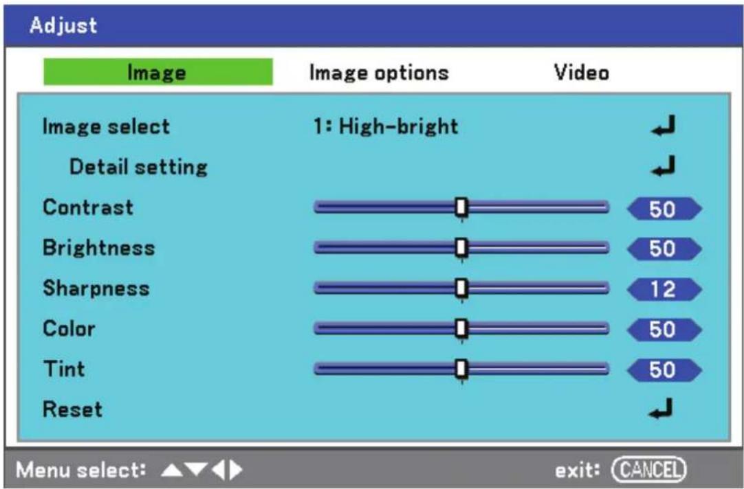
The following table lists all functions with a description and the default setting.
| LABEL DESCRIPTION | |
| Image select | Select a set of preset values using ◀ or ▶ from the list. Notice that the below values will change depending on the preset selection. |
| Detail setting | See Detail Setting Menu Descriptions and Functions on page 55. |
| Contrast | Adjust the Contrast value using ◀or▶ to highlight the differences between light and dark areas of the picture. |
| Brightness | Adjust the Brightness value using ◀or▶ to lighten or darken the picture. |
| Sharpness | Adjust the Sharpness value using ◀or▶ to sharpen or blur the borders between colors and objects. |
| Color | Adjust the Color value using ◀or▶ to increase or decrease color input to the picture. |
| Tint | Adjust the Tint value using ◀or▶ to increase or decrease the color hue of the picture. |
| Reset The settings and adjustments are set to initial factory settings. | |
Image options menu
The Image Options tab is used to configure image options such as screen positioning and aspect ratio. Access the Image Options tab in the Adjust menu.

The following table lists all functions with a description and the default setting.
| LABEL DESCRIPTION | |
| Screen | Select Screen using ◀or▶ from the list (see page 51). |
| Overscan | Set the Overscan value using ◀or▶ (see page 51). |
| PC adj. | Adjust the position values using the slides HVorizontal: Adjusts the image location horizontally using ◀or▶.Vertical: Adjusts the image location vertically using ◀or▶.Total dots: Fine tune a computer image or remove any vertical banding that might appear.Fine sync: Adjust the clock phase or reduce video noise, dot or cross talk.Note:Only useFine syncafter the total dots settings have been modified. |
Screen
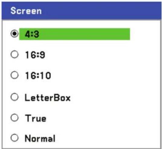
The Screen option allows for the adjustment of the aspect ratio to alter the appearance or ratio of the projected image.
bar
Screen | Category | Value | |---|---| | 4:3 | 4:3 | | 16:9 | 16:9 | | 16:10 | 16:10 | | LetterBox | | True | | Normal |4:3 – Standard TV screen (4:3), proportionally four units wide for every three units high, no matter the size of the screen.
16:9 - A wide-screen aspect ratio for video.
16:10 - A wide-screen aspect ratio for video.
LetterBo – Reduce image to display the true aspect with black borders on top and bottom.
True - Displays the current image in its true resolution.
Normal – Displays the current image in its aspect ratio.
Overscan
Video images normally exceed the size of the display screen. The edge of the picture may or may not be displayed correctly. The border area that is cropped can be adjusted by using the Overscan option.

bar
Overscan | Category | Value (%) | |---|---| | OK | 0 | | Cancel | 0 |Set the overscan percentage between 0 – 15% to compensate for different screen sizes.
Video menu
The Video tab is used to configure image options such as film. Access the Video tab in the Adjust menu.

The following table lists all functions with a description and the default setting. A detailed description follows the table.
| LABEL DESCRIPTION | |
| Noise reduction | Select Noise reduction mode (see page 53). |
| 3D Y/C separation | Select 3D Y/C separation mode (see page 53). |
| Progressive Select Progressive mode (see page 53). | |
| Color matrix Select Color matrix mode (see page 54). | |
| Film Select Film mode (see on page 54). | |
Noise reduction
Select the level of noise reduction required.

Range: Off, Low, Mid, High.
3D Y/C separation
3D Y/C Separation separates composite signal to Y (brightness) signal and C (color) signal, and can help to produce clearer and sharper images without overlapping colors (rainbow effect).

Set 3D Y/C Separation On or Off.
Progressive
Progressive converts an interlaced image to a progressive scan image.

Select the form of Deinterlacing required from:
Still – Select for stills such as slide projections or screen shots.
Normal – Select Normal for non-specialized projection.
Movie – Select for movie projection.
Color matrix
Color Matrices define the amount of the three-color components R (red), G (green), and B (blue) in a single point in color space.

Select from the following:
Auto – Auto selects the color matrix.
RGB – Sets the color matrix to RGB, use for PC monitor or camera imaging.
SDTV – Sets the color matrix to SDTV, use for Standard Definition imaging.
HDTV – Sets the color matrix to HDTV, use for High Definition imaging.
Film
Film aids in converting motion picture film images into video. The process adds additional frames to the picture in order to increase the frame rate.
Note:
This feature is only available when Progressive is turned on and SDTV signal is selected.

Select from the following:
Off – Film mode is turned off.
2-2/2-3 Auto – Detects pull-down correction method.
2-2 On – Uses 2-2 pull-down correction method.
2-3 On - Uses 2-3 pull-down correction method.
Detail Setting Menu Descriptions and Functions
The Detail setting menu contains basic and advanced color adjustment options such as gamma correction, color contrast and color correction.
Basic
The Basic tab contains general setting such as gamma correction and color temperature. Access to the Basic tab is through the Detail setting menu.
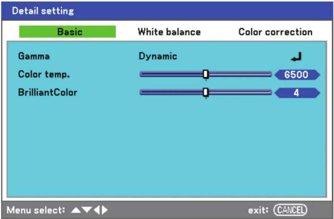
The following table lists all functions with a brief description.
| LABEL DESCRIPTION | |
| Gamma Select Gamma | Correction mode (see page 56). |
| Color temp. | Move the slider bar left or right to set the color temperature value in Kelvin (K).Compensate for the amount of light available. Daylight is approximately 5500K. |
| BrilliantColor | Move the slider bar left or right to set the BrilliantColorTMvalue. BrilliantColor extends the exposure range and sharpens detail for grain free images. |
Gamma
Gamma enables adjustment to the light intensity (brightness) of an image in order to match the source more closely.

Select from the following:
Dynamic - Allows the projector to alter the gamma correction automatically.
Natural – Attempts to emulate the original source as closely as possible.
Black detail – Black detail highlights boundaries between light and dark areas of the image more clearly.
White balance
White Balance allows the projector to compensate for different colors of light being emitted by different light sources.

The following table lists all functions with a brief description.
| LABEL DESCRIPTION |
| Red Set the value to compensate for red light sources. |
| Green Set the value to compensate for green light sources. |
| Blue Set the value to compensate for blue light sources. |
| Contrast R Set the Contrast R value to compensate for red light sources. |
| Contrast G Set the Contrast G value to compensate for green light sources. |
| Contrast B Set the Contrast B value to compensate for blue light sources. |
Color correction
The Color correction tab enables the adjustment of color values in an image to remove unwanted effects, improve color, characteristics or add more of a particular color.

The following table lists all functions with a brief description.
| LABEL DESCRIPTION | |
| Red | Increase or decrease the amount of red in the projected output using ◀ and ▶. |
| Green | Increase or decrease the amount of green in the projected output using ◀ and ▶. |
| Blue | Increase or decrease the amount of blue in the projected output using ◀ and ▶. |
| Yellow | Increase or decrease the amount of yellow in the projected output using ◀ and ▶. |
| Magenta | Increase or decrease the amount of magenta in the projected output using ◀ and ▶. |
| Cyan | Increase or decrease the amount of cyan in the projected output using ◀ and ▶. |
Setting Menu Descriptions and Functions
The Setting menu contains the most often used settings during installation and options to customize the general output of the projector. Three tabs are accessible through the Setting menu, Basic, Installation and Option.
Basic
The Basic tab contains general setup options such as lamp mode and OSD language settings and can be accessed with the projector control panel or with the remote control unit.

The following table lists all functions with a brief description.
| LABEL DESCRIPTION | |
| Keystone | Adjust the Keystone trapezoid (see Keystone page 60). |
| Lamp control Select | Lamp control. Range: Normal or Eco. |
| Lamp mode Select | Lamp configuration. Range: Dual, Lamp1 or Lamp2. |
| Lamp interval Select | Lamp interval. Range: Off, 1 week, 4 weeks or 2000 hours. |
| Language | Select the OSD language (see Language on page 61). |
| Lens Shift | Displays the Lens Shift window (see Adjusting Picture Position Manually on page 24). |
| Zoom | Displays the Zoom window (see Adjusting the Focus/Zoom Manually on page 34). |
| Focus | Displays the Focus window (see Adjusting the Focus/Zoom Manually on page 34). |
Keystone
The keystone trapezoid can be adjusted by selecting this option.

Select Horizontal or Vertical using ▲or▼ then, use ◀or▶ to adjust the projected image appearance as required.
Note:
When adjusting the keystone, place the projector in the following position.
• Horizontal: set to the lens center
• Vertical: set to the maximum top
Lamp control
Select Normal or Eco from the lamp mode window. The lamp life can be extended by using the Eco mode and the fan noise can be reduced.
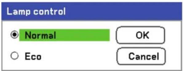
Lamp mode
Select the lamps to be used for projection.

Select from the following:
Dual – Uses both lamps simultaneously.
Lamp1 – Uses Lamp1 only.
Lamp2 – Uses Lamp2 only.
Lamp interval
The period of time for regulating lamp usage when not in dual lamp mode.

Select from the following:
Off, 1 week, 4 weeks and 2000H
Language
Select the OSD language to be used.
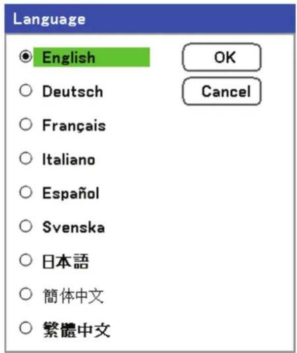
Select from the following:
- English
German
French
Italian - Spanish
- Swedish
- Japanese
- Simplified Chinese
■ Traditional Chinese
Installation
The Installation tab contains menu options for various setup conditions such as orientation and remote sensor mode and is accessed through the Setting menu.
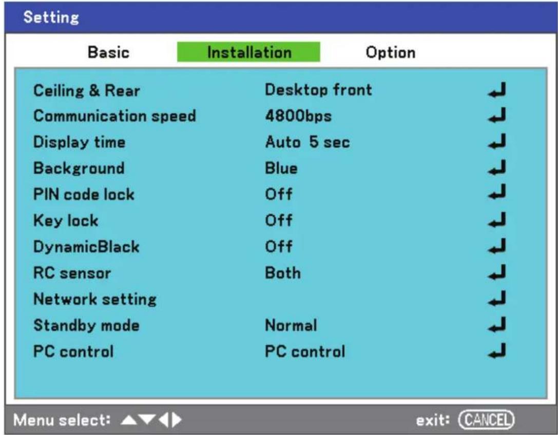
The following table lists all functions with a brief description.
| LABEL DESCRIPTION | |
| Ceiling & Rear | Select from four projection methods depending on projection site (see Ceiling & Rear page 63). |
| Communication speed | Select Communication speed.Range: 4800bps, 9600bps, 19200bps, 38400bps |
| Display time | Select Display time.Range: Manual, Auto 5s, Auto 15s, Auto 45s |
| Background | Select Background appearance when there is no signal.Range: blue, black or logo |
| PIN code lock | Set PIN code lock On/Off (see PIN Code Lock on page 64). |
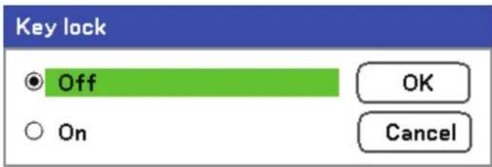
| Key lock | Set Control panel lock On/Off.Note:This Control Panel Lock does not affect the remote control functions.When the control panel is locked, pressing and holding the Cancel button on the projector cabinet for about 10 seconds. The setting will change to Off. |
| DynamicBlack | DynamicBlackTM improves the black level of the projector. Black level is the darkest part of a picture and varies between viewing devices and environments. Set DynamicBlack on/off. |
| RC sensor | Set RC sensor fields.Range: Both, Front, Back |
| Network setting | Opens Network preferences tab (see Network setting on page 65). |
| Standby mode | Select Standby mode.Range: Normal and Power-saving |
| PC control | Enables the path selection for PC control.Range: PC control or Network. |
Ceiling & Rear
Ceiling & Rear enables you to set how the projected image is displayed.
Select from the following:
Desktop Front – Standard forward facing projection (Default setting).
Desktop Rear – Standard rear projection. Enables the projector to produce the image from behind the screen by reversing the image.
Ceiling Front – Forward facing ceiling mounted projection. Enables ceiling mounted projection by inverting the image.
Ceiling Rear – Rear ceiling mounted projection. Enables ceiling mounted projection from behind the screen by inverting and reversing the image.
Communication speed
Select communication speed to set the baud rate of the connection.
Note:
Longer cable connections may require lower settings.
Communication speed

4800bps

9600bps

19200bps

38400bps
OK
Cancel
Select from the following options:
4800bps
9600bps
19200bps
■ 38400bps
Note:
In the Network mode, Communication Speed function is not available.
Display time
Sets the amount of time a menu is displayed.

Select from the following:
Manual – Menus stay on screen until the Menu button is pressed again.
Auto 5 secs—Menu is displayed for 5 seconds.
Auto 15 secs – Menu is displayed for 15 seconds.
Auto 45 secs – Menu is displayed for 45 seconds.
Background
Background enables you to display a blue/black screen when there is no signal. The default background is blue.

Select from the following:
Blue
Black
- Logo
PIN Code Lock
See Preventing the Unauthorized Use of the Projector on page 40.

PIN code lock function will be enabled.
Are you sure?


Key lock
Turn On/Off the Key Lock function for cabinet buttons.
Note:
- This Control Panel Lock does not affect the remote control functions.
- When the control panel is locked, press and holding the Cancel button on the projector cabinet for about 10 seconds. The setting will change to Off.
DynamicBlack
DynamicBlack ^TM enables you to improve the black level of the projector.

RC sensor
Set the operating range for the wireless remote control.

Select from the following:
Both
Front
■ Back
Network Setting
See Network setting on page 67.
Standby mode
There are two standby modes available: Normal and Power-saving. Power-saving mode allows you to put the projector in the standby condition to consume less power than Normal.

Note:
Be sure to connect the projector and computer while the projector is in standby mode and before turning on the computer.
Select from the following:
Normal
Power-saving
Note:
The HTTP server functions are not available during Power-saving mode.
The MONITOR OUT function is not available during Power-saving mode.
Control through the PC Control connector and Network mode is not available during Power-saving mode. For PC control and Network mode of the projector it is recommended to leave the projector in the Normal mode.
Normal mode: POWER indicator: Orange light WARNING indicator: Green light Power-saving mode: POWER indicator: Orange light WARNING indicator: Off
PC control
This function enables you to select the path for PC control (see PC Control Codes and Cable Connections on page 95).

Note:
In the Network mode, Communication Speed function is not available.
Select from the following:
PC control
Network
Network setting
The Network setting menu is accessed by using the Setup/Installation menu and contains the general LAN settings.

The following table lists all functions with a description and the default setting.
| LABEL DESCRIPTION | |
| DHCP | Select either a static IP (Disable) or DHCP IP (Enable) setting by selecting the appropriate radio button. |
| IP address Displays the subnet mask. | P address. |
| Gateway | Enable or disable the network gateway setting. Click on the radio button to change the setting. |
| DNS | Enable or disable the DNS server settings. Click on the radio button to change the setting. |
| Apply settings Apply and save settings. | |
Option
The Option tab contains miscellaneous setup menu settings such as Power management and Default input select and can be accessed by using the Setting menu.
| Setting | ||
| Basic | Installation | Option |
| Power management | Off | |
| Screen trigger | Off | |
| Fan control | Max | |
| Default input select | Last | |
| Color system | ||
| Video | Auto | |
| S-Video | Auto | |
| Message | Off | |
| Filter warning | Off | |
| Search mode | Fine | |
The following table lists all functions with a description and the default setting.
| LABEL DESCRIPTION | |
| Power management | Select the amount of time the projector remains idle before powering down. Range: Off, 0:05, 0:10, 0:20, 0:30 |
| Screen trigger | Set this item to On to enable the projector to automatically lower the projection screen when powering on. Range: On or Off |
| Fan control | Select Fan control. Range: Normal or Max (see Fan control page 69) |
| Default input select | Select the default input for projection. Range: Last, Auto, Computer1, Computer2, Computer3, Component, Video, S-Video |
| Color System | Video—select the Video Color System from Auto, NTSC, PAL, and SECAM. |
| S-Video— select the S-Video Color System from Auto, NTSC, PAL, and SECAM. | |
| Message | This option turns on or off messages. Range: Off or On |
| Filter warning | Set this item to on to have the projector display a message when the air filter needs servicing. Range: Off, 100[H], 200[H], 500[H], 1000[H] |
| Search mode | This feature sets the Auto Adjust mode. Range: Normal, Fine |
Power management
Power management enables the projector to automatically turn off if there is no signal received by any input.

Select from the following:
Off
5 minutes
■ 10 minutes
■ 20 minutes
■ 30 minutes
Screen trigger
Set Screen trigger to On to enable the projector to automatically lower the projection screen when powering on. When powering off, Screen trigger stops sending a low voltage trigger to the screen controller and the screen goes up.
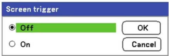
Fan control
Fan control is used to set the speed of the internal cooling fan. Set Fan Speed to Max in altitudes over 1500 meters (5000 feet).
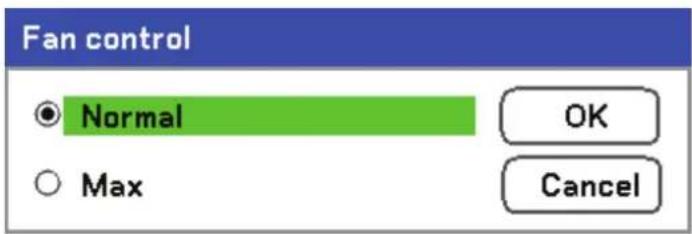
The Fan control option default is Normal, which enables the projector to automatically detect fan requirements. For higher temperature locations or prolonged use, the Max option is available to provide greater cooling capacity.
Default input select
The Default input is the image source that the projector will search for automatically on startup.

Last – Uses the most recently used image source.
Auto – Auto detects the default image source.
Computer1/2/3 – Uses Computer1, 2 or 3 as the default image source.
Component – Uses last component as the default image source.
Video – Uses last video input as default image source.
S-Video – Uses last S-video input as default image source.
Message
This option turns on or off messages. Even though selecting [Off], the following message will appear. "Projector is locked" when the projector security is unlocked, the message will disappear.

Filter warning
Set Filter warning to have the projector display a message when the air filter needs servicing.
![Filter warning Off 100[H] 200[H] 500[H] 1000[H] OK Cancel](/content/2026/05/1054913/images/7afa1fe2325b75e18e4e31e7b418daad3ba038a66375d45626d36193d5f08a13.jpg)
The message below shows when this function is activated.
Please clean filter.
Search mode
This feature sets the Auto Adjust mode so that the RGB image can be automatically or manually adjusted for noise and stability. You can automatically make adjustments in two ways: [Normal] and [Fine].

Normal: The RGB image will be automatically adjusted. Normally select this option (Default).
Fine: Select this option if fine adjustment is needed. It takes more time to switch to the source than the Normal settings.
Information Menu Descriptions and Functions
The Information menu provides only screens for the quick access of menus. The Information menu contains four distinct tabs.
Usage time
The Usage time tab displays information about lamp usage and remaining lamp life.
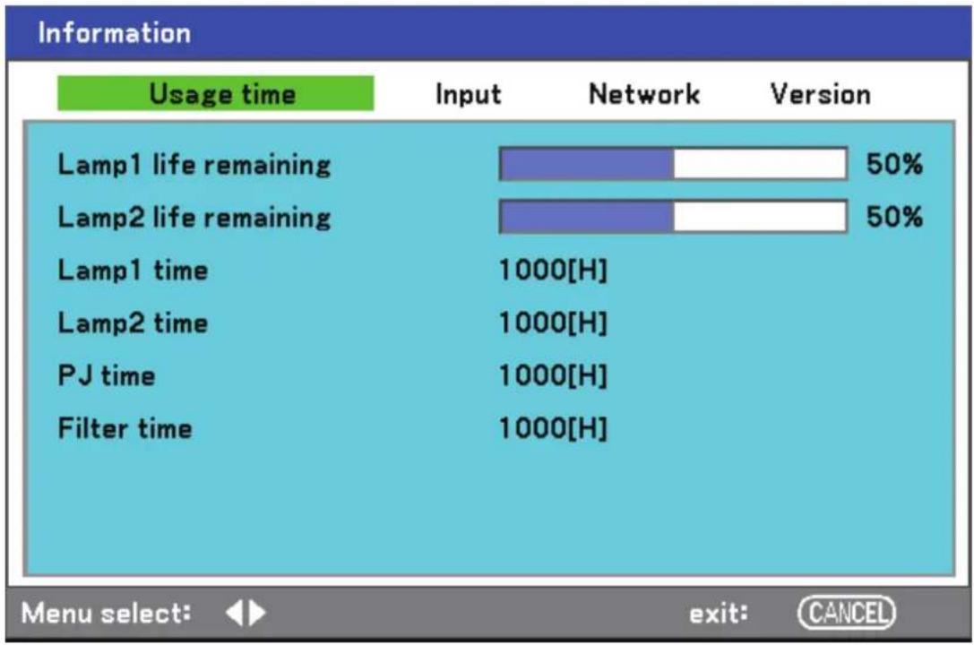
bar
Information | Usage time | Input | Network | Version | |---|---|---|---| | Lamp1 life remaining | 50% | 50% | 50% | | Lamp2 life remaining | 50% | 50% | 50% | | Lamp1 time | 1000[H] | | | | Lamp2 time | 1000[H] | | | | PJ time | 1000[H] | | | | Filter time | 1000[H] | | | Menu select: ▶ exit: CANCELThe following table lists all items with a description.
| LABEL DESCRIPTION | |
| Lamp1 life remaining Displays the Lamp1 life remaining as a percentage. | |
| Lamp2 life remaining Displays the Lamp2 life remaining as a percentage. | |
| Lamp1 time Displays the Lamp1 total usage in hours. | |
| Lamp2 time Displays the Lamp2 total usage in hours. | |
| PJ time Displays the projector total usage in hours. | |
| Filter time Displays how many hours the filter has been used. |
Input
The Input tab displays various source and frequency values at a glance.
| Usage time | Input | Network | Version |
| Input name | Computer2 | ||
| Signal | 1024x768 | ||
| H-sync. freq. | 48.36[kHz] | ||
| V-sync. freq. | 60.00[Hz] | ||
| Video type | --- | ||
| Sync type | Separate sync | ||
| Sync polarity | H:(-)V:(-) | ||
| Scan type | Non-Interlace | ||
The following table lists all items with a description.
| LABEL DESCRIPTION | |
| Input name | Displays the Input Terminal that is presently being used (see Default input select on page 70). |
| Signal Displays the Source name of the signal presently being used. | |
| H-sync. freq. Displays Horizontal frequency in KHz. | |
| V-sync. freq. Displays Vertical frequency in Hz. | |
| Video type Displays Video type. | |
| Sync type Displays Sync type. | |
| Sync polarity Displays Sync polarity. | |
| Scan type Displays Scan type. | |
Network
The Network tab displays LAN settings as previously defined (see Network setting on page 67).

Version
The Version tab displays all the version and product details of the projector and associated software (for display only).
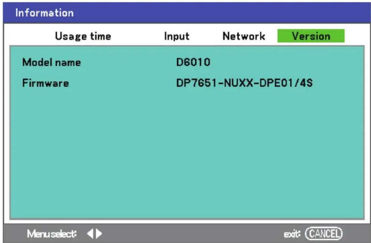
The following table lists all items with a description.
| LABEL DESCRIPTION | |
| Model name Displays Product ID. | |
| Firmware Displays Firmware version and Color Wheel currently installed (4-seg or 6-seg). |
Reset Menu Descriptions and Functions
Occasionally, circumstances may require that factory defaults be reset, for demonstration purposes for example, or when components are replaced.
The Reset menu contains options for returning settings to the factory default and is accessed by using the Main menu.

The following table lists all items with a description.
| LABEL DESCRIPTION | ||
| Current signal | Reset the adjustments for current signal to factory-preset levels. All items in Ad-just can be reset. | |
| All data | Resets all options to factory default regardless of when they were changed. Reset all the adjustments and settings for all the signals to the factory preset ex-cept Language, Background, Key lock, Security, Network Mode, Communication Speed, Lamp life remaining, Lamp time, and Filter time. | |
| Clear lamp1 time Reset | amp1 time | These options should only be used when compo-nents are cleaned or replaced (see Maintenance on page 77) |
| Clear lamp2 time Reset | amp2 time | |
| Clear filter time Reset filter hours | ||
Cleaning the projector
Cleaning the Cabinet
Refer to the following guide to clean the projector cabinet.
- Wipe off dust with a clean dampened cloth.
- Moisten the cloth with warm water and mild detergent and wipe the cabinet.
- Rinse all detergent from the cloth and wipe the projector again.
Caution:
To prevent discoloration or fading of the case, do not use abrasive alcohol-based cleaners.
Cleaning the Lens
Refer to the following guide to clean the projector lens.
- Apply a little optic lens cleaner to a clean, lint free cloth (do not apply the cleaner directly to the lens).
- Lightly wipe the lens in a circular motion.

natural_image
Illustration of a hand cleaning a projector with a cloth (no text or symbols)Caution:
- Do not use abrasive cleaners or solvents.
- To prevent discoloration or fading, avoid getting cleaner on the projector case.
Cleaning the Filters
The projector uses three filters to keep the fans free of dust and other particles, and should be cleaned every 500 hours of operation. In dusty environments, it is recommended to clean the filters more frequently. If the filter is dirty or clogged, your projector may overheat. When the message below is displayed, the filters must be cleaned.
Please clean filter.
Note:
When the Please clean filter message is displayed, please clean all three filters at the same time to synchronize the Filter time display.
The Filter Message item should be enabled in the Options menu. Refer to Option on page 68.
Refer to the following guide to clean the filters.
- The left-side and rear filters can be cleaned as demonstrated in the following images.
Note: Only clean the outside of the exhaust vents with a vacuum cleaner.

natural_image
Line drawing of a projector with control panel and drive mechanism (no text or symbols)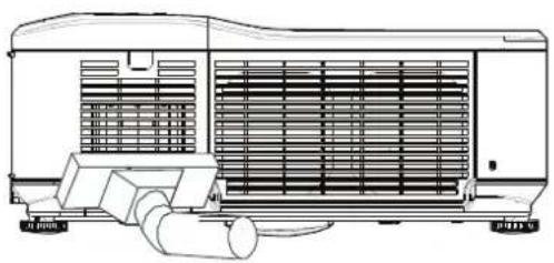
natural_image
Technical line drawing of an air conditioning unit with cooling fan and pump (no text or symbols)- The rear exhaust vent can be accessed as shown.

natural_image
Pure technical diagram of a mechanical component without any text, numbers, or symbols- Gently slide the filter holders in the direction shown.

- Lift the filter foams from all three filteholders in the direction shown. Remove them completely from each filterholder and discard.
- Place a replacement foam and press down firmly
- Replace the filter holders by pushing gently in the direction shown.

natural_image
Technical line drawing of a mechanical component with an arrow indicating rotation (no text or symbols)
natural_image
Isometric line drawing of a modular device with a black arrow indicating a component or feature (no text or symbols)
Once the filters are cleaned, please reset the filter hours by using the Clear filter time option in the Reset Menu Descriptions and Functions on page 76.
Replacing the Lamps
When a lamp reaches the end of it's usable life, the following message is displayed. Replace the lamp.
The lamp has reached the end of its usable life. Please replace the lamp.
The projection lamps should be replaced when they burn out. They should only be replaced with a certified replacement part, contact your local dealer if unsure.
Note:
- Lamps are positioned differently. Take care not to force the lamps when replacing.
- Installation of both lamp modules (Lamp 1 and Lamp 2) is required to operate the projector in dual or single lamp mode. If only a single lamp module is installed, the projector's lamp will not turn on and will appear as a lamp failure.
- Lamps last approximately 2000-2100 hours (2500-2600 hours in Eco mode) and the End of lamp life message is displayed during the lamps' final 100 hours of operational life. Please replace during 2000-2100 hour.
Important:
- The lamp contains a certain amount of mercury and should be disposed of according to local ordinance regulations.
- Avoid touching the glass surface of the new lamp: doing so may shorten its operation life.
Caution:
Lamp Handling Precautions
- This projector uses a high-pressure lamp which must be handled carefully and properly. Improper handling may result in accidents, injury, or create a fire hazard.
- Lamp life may differ from lamp to lamp and according to the environment of use. There is no guarantee of the same life for each lamp. Some lamps may fail or terminate their life in a shorter period of time than other similar lamps.
- If the projector indicates that the lamp should be replaced, i.e., if LAMP 1 and/or LAMP 2 light up, replace the lamp with a new one IMMEDIATELY after the projector has cooled down. (Follow carefully the instructions in the Lamp Replacement section of this manual.) Continuous use of the lamp with LAMP 1 and/or LAMP 2 lighted may increase the risk of lamp explosion.
- A Lamp may explode as a result of vibration, shock or degradation as a result of hours of use as its lifetime draws to an end. Risk of explosion may differ according to the environment or conditions in which the projector and lamp are being used.
If a lamp explodes, the following safety precautions should be taken:
Disconnect the projector's AC plug from the AC outlet immediately. Contact an authorized service station for a checkup of the unit and replacement of the lamp. Additionally, check carefully to ensure that there are no broken shards or pieces of glass around the projector or coming out from the cooling air circulation holes. Any broken shards found should be cleaned up carefully. No one should check the inside of the projector except those who are authorized trained technicians and who are familiar with projector service. Inappropriate attempts to service the unit by anyone, especially those who are not appropriately trained to do so, may result in an accident or injury caused by pieces of broken glass.
The projection lamp should be replaced when it burns out. It should only be replaced with a certified replacement part, which you can order from your local dealer.
Important:
a. The lamp contains a certain amount of mercury and should be disposed of according to local ordinance regulations.
b. Avoid touching the glass surface of the new lamp: Doing so may shorten its operation life.
Warning:
Be sure to turn off and unplug the projector at least 30 minutes before replacing the lamp. Failure to do so could result in a severe burn.
Note:
Safety glasses should be worn when replacing the lamp while the projector is ceiling mounted.
- Remove the four screws on the lamp cover (A), and lift the lamp cover as shown (B).

- Loosen the two captive screws on the lamp module (A). Lift the module handle up as shown (B).

-
Pull firmly on the module handle in the direction shown to remove the lamp.
-
Reverse steps 1 to 3 to install the new lamp module(s) and replace the lamp cover.
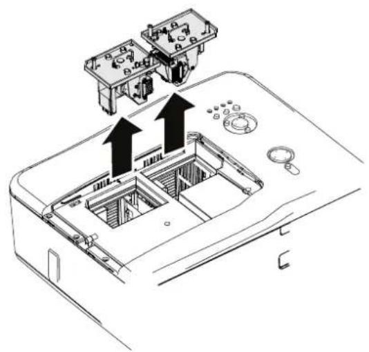
natural_image
Technical line drawing of a device interior with two labeled components and upward arrows indicating motion (no text or symbols present)
natural_image
Technical line drawing of a device interior with two labeled components and arrows indicating assembly or movement (no text or symbols present)Resetting the Lamp Time Counter
After replacing the lamp(s), the lamp hour counter(s) should be reset to zero. Refer to the following guide:
- Press the Menu button on the OSD control panel or Remote Control to open the Main menu.

-
Press the ▲ or ▼ button to move to the Reset menu and press ←.
-
The Reset menu is displayed. Select Clear lamp1 time or Clear lamp2 time as required using ▲or▼ and press ←.
-
A confirmation box is displayed. Select OK using ◀ or ▶ and press ← to reset the selected Lamp hours to zero.


Troubleshooting
Indicator Messages
Several indicator messages are used by the projector to alert users of problems with setup or internal parts. The LEDs on the top surface of the projector show the status of the WARNING and lamp 1/2 as well as the general working order of the projector through the WARNING LED (see OSD Controls and Status LEDs on page 4 for location). The following tables describe the various states of the 4 LEDs.
The POWER LED
| PROJECTOR STATUS | LED CONDITION | LED SEQUENCE | PROJECTOR CONDITION |
| AC off Off Off Off | |||
| Cooling | Orange | 0.5 secs on 0.5 secs off | After power off |
| Power up sequence Green blink | 0.5 secs on 0.5 secs off | Start up | |
| Standby | Orange | on | On |
| Power on Green on On | On | ||
The WARNING LED
| PROJECTOR STATUS | LED CONDITION | LED SEQUENCE | PROJECTOR CONDITION |
| Normal condition Off Off | Power on | ||
| Cover ERROR | Red 1 time blink (repeatedly) | 0.5 secs on2.5 secs off | ERROR |
| Temperature ERROR | Red 2 times blink (repeatedly) | (0.5 secs ON > 0.5 secs OFF) * 2 > 2.0 secs OFF | ERROR |
| Power ERROR | Red 3 times blink | (0.5 secs ON > 0.5 secs OFF) *3 > 2.0 secs OFF | ERROR |
| Fan ERROR | Red 4 times blink (repeatedly) | (0.5 secs ON > 0.5 secs OFF) * 4 > 2.0 secs OFF | ERROR |
| Keylocked (when push key) | Orange light up | On | Keylocked function enabled |
| Standby (Power-saving) | Off | Off | Standby (Power-saving) |
| Standby (Normal) | Green light | On | Standby (Normal) |
The LAMP LEDs
| PROJECTOR STATUS | LED CONDITION | LED SEQUENCE | PROJECTOR CONDITION |
| Lamp off Off Off Lamp off | |||
| End of the lamp life Red blink | 0.5 secs on0.5 secs off | Replace lamp | |
| No lamp | Red 1 time blink(repeatedly) | 0.5 secs on2.5 secs off | ERROR |
| Lamp ERROR | Red 6 times blink(repeatedly) | (0.5 secs ON > 0.5 secs OFF) * 6 > 2.0 secs OFF | ERROR |
| Cooling lamp Orange blink | 0.5 secs ON > 0.5 secs OFF | Switching lamp1 and 2 | |
| Re-light up sequence Green blink | 0.5 secs ON > 0.5 secs OFF | Start up | |
| Lamp life over Red on On Replace lamp | |||
| Eco mode Orange on On Power on | |||
| Normal mode Green on On | Power on |
Common Problems and Solutions
These guidelines provide tips to deal with problems you may encounter while using the projector. If the problem remains unsolved, contact your dealer for assistance.
Often the problem is something as simple as a loose connection. Check the following before proceeding to the problem-specific solutions.
• Use some other electrical device to confirm that the electrical outlet is working.
- Ensure the projector is turned on.
- Ensure all connections are securely attached.
• Ensure the attached device is turned on.
- Ensure a connected PC is not in suspend mode.
- Ensure a connected notebook computer is configured for an external display. (This is usually done by pressing an Fn-key combination on the notebook.)
Tips for Troubleshooting
In each problem-specific section, try the steps in the order suggested. This may help you to solve the problem more quickly.
Try to pinpoint the problem to avoid replacing non-defective parts.
For example, if you replace batteries and the problem remains, put the original batteries back and go to the next step.
Keep a record of the steps you take when troubleshooting: The information may be useful when calling for technical support or for passing on to service personnel.
Image Problems
Problem: No image appears on the screen
- Verify the settings on your notebook or desktop PC.
- Turn off all equipment and power up again in the correct order.
Problem: The image is blurred
- Adjust the Focus on the projector.
- Press the AUTO button on the remote control or projector.
- Ensure the projector-to-screen distance is within the specified range.
- Check that the projector lens is clean.
- Remove the lens cover.
Problem: The image is wider at the top or bottom (trapezoid effect)
- Position the projector so it is as perpendicular to the screen as possible.
- Use the Keystone button on the remote control to correct the problem.
Problem: The image is reversed or upside down
- Check the Ceiling & Rear setting on the Setting menu of the OSD.
Problem: The image is streaked
- Set the Total dots and Fine sync. settings on the Adjust menu of the OSD to the default settings.
- To ensure the problem is not caused by a connected PC's video card, connect to another computer.
Problem: The image is flat with no contrast
- Adjust the Contrast setting on the Adjust menu of the OSD.
- Adjust the Brightness setting on the Adjust menu of the OSD.
Problem: The color of the projected image does not match the source image.
- Adjust the Color temp. and Gamma settings on the Detail setting menu of the OSD.
Lamp Problems
Problem: There is no light from the projector
- Check that the power cable is securely connected.
- Ensure the power source is good by testing with another electrical device.
- Restart the projector in the correct order and check that the Power LED is green.
- If you have replaced the lamp recently, try resetting the lamp connections.
- Replace the lamp module.
- Remove the lens cap.
- Put the old lamp back in the projector and have the projector serviced.
Problem: The lamp goes off
- Power surges can cause the lamp to turn off. Press the power button twice to turn off the projector. When the Power LED is orange, press the power button.
- Replace the lamp module.
- Put the old lamp back in the projector and have the projector serviced.
Remote Control Problems
Problem: The projector does not respond to the remote control
-
Direct the remote control towards remote sensor on the projector.
-
Ensure the path between remote and sensor is not obstructed.
-
Turn off any fluorescent lights in the room.
-
Check the battery polarity.
-
Replace the batteries.
-
Turn off other Infrared-enabled devices in the vicinity.
-
Have the remote control serviced.
-
Ensure that the remote control code conforms to the projector's code.
-
Ensure that the reset switch in the compartment lid on back of the remote control is set to use position.
Audio Problems
Problem: There is no sound
-
Adjust the volume on the remote control.
-
Adjust the volume of the audio source.
-
Check the audio cable connection.
-
Test the source audio output with other speakers.
-
Have the projector serviced.
Problem: The sound is distorted
-
Check the audio cable connection.
-
Test the source audio output with other speakers.
-
Have the projector serviced.
Having the Projector Serviced
If you are unable to solve the problem, you should have the projector serviced. Pack the projector in the original carton. Include a description of the problem and a checklist of the steps you took when trying to fix the problem. The information may be useful to the service personnel. Return the projector to the place you purchased it.
Projector Specifications
This section provides technical information about the projector's performance.
Optical Specifications
| ITEM DESCRIPTION | |
| Projection system Single DLP® chip, 4 segment color wheel | |
| Resolution | 1280 x 800 pixels* (up to UXGA @ 60 Hz) |
| Lamp 280 W AC (230 W in Eco mode), Dual lamp system | |
| Image size (diagonal) | 50" - 200" / 1.27m - 5.08m (GC805G)40" - 500" / 1.02m – 12.7m (GB942G, GB940G, GB949G, GB957G) |
| Lens options | GC805G: Power focus, throw ratio 0.77:1, F2.0, f=11.4 mmGB942G: Power zoom and focus, throw ratio 1.33-1.79:1, F1.8-2.3, f=19.3-25.8 mmGB940G: Power zoom and focus, throw ratio 1.78-2.35:1, F1.7-1.9, f=26-34 mmGB949G: Power zoom and focus, throw ratio 2.22-4.43:1, F2.1-2.9, f=32-63 mmGB957G: Power zoom and focus, throw ratio 4.43-8.3:1, F2.2-3.1, f=63.5-117.4 mm |
| Lens shift Vertical + 0.5V, Horizontal +/- 0.1H (GB942G, GB940G, GB949G, GB957G) | |
*Effective pixels are more than 99.99%
Electrical Specifications
| ITEM DESCRIPTION | |
| Inputs | 1 Analog RGB (Mini D-Sub 15P), 1 Analog RGB R/Cr, G/Y, B/Cb, H, V (BNC x 5), 1 Digital RGB (DVI-D 24P), 1 Component Y, Cb/Pb, Cr/Pr (RCA x 3), 1 Component (Mini D-Sub 15P) shared with COMPUTER 1 IN, 1 S-Video (Mini DIN 4P), 1 Video, 3 Stereo Mini Audio, 2 (L/R) RCA Audio |
| Outputs | 1 RGB (Mini D-Sub 15P), 1 Stereo Mini Audio, 1 Screen Trigger |
| Control 1 PC Control Port (D-Sub 9P) | |
| USB Port 1 B Type (for Service) | |
| LAN Port RJ-45 | |
| Video Compatibility | NTSC, NTSC4.43, PAL, PAL-60/N/M/B/G/H/I), SECAM, HDTV: 1080p,1080i, 720p, SDTV: 576p, 576i, 480p, 480i |
| Scan Rate | Horizontal: 15 kHz, 31 to 90 kHz (RGB: 31 kHz or over) Vertical: 50 Hz to 85 Hz |
| Video Bandwidth RGB: 100 MHz (-3dB) | |
| Color Reproduction 16.7 million colors simultaneously, Full color | |
| Horizontal Resolution NTSC | / NTSC4.43 / PAL / PAL-M / PAL-N / PAL60: 540 TV linesSECAM: 300 TV linesRGB: 1280 dots (H) x 800 dots (V) |
| External Control RS232, IR, | LAN |
| Sync Compatibility | Separate Sync / Composite Sync / Sync on G |
| Built-in Speakers | 5W x 2 |
| Power Requirement 100 - 240V AC, 50/60Hz | |
| Input Current 7.4A | |
| Power Consumption | 730W in Dual Lamp Normal mode / 570W in Dual Lamp Eco mode380W in Single Lamp Normal mode / 310W in Single Lamp Eco mode< 30W in Standby mode Normal< 5W in Standby mode Power saving |
Mechanical Specifications
| ITEM DESCRIPTION | |
| Dimensions | 20" (W) x 7.7" (H) x 15.3" (D)508 mm (W) x 195 mm (H) x 389 mm (D)(not including protrusions) |
| Weight 37.5 lb/17 kg | |
Environmental Considerations
| ITEM DESCRIPTION | |
| Operational Temperatures | 41° to 104°F / 5° to 40°C, 10% to 90% humidity (non-condensing) |
| Storage Temperatures | 14° to 140°F (-10° to 60°C), 5% to 90% humidity (non-condensing) |
Optional Parts
The parts listed below are optionally available. When ordering those parts, specify the item name and Model No. to the sales dealer.
Standard Zoom Lens : GB940G
Long Zoom Lens : GB949G
Ultra Long Zoom Lens : GB957G
Short Zoom Lens : GB942G
Fixed Short Zoom Lens : GC805G
Cabinet Dimensions
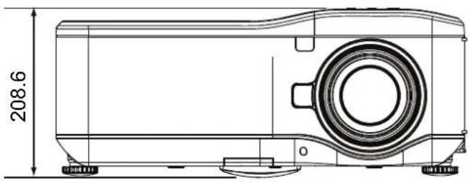
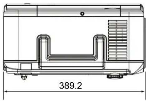
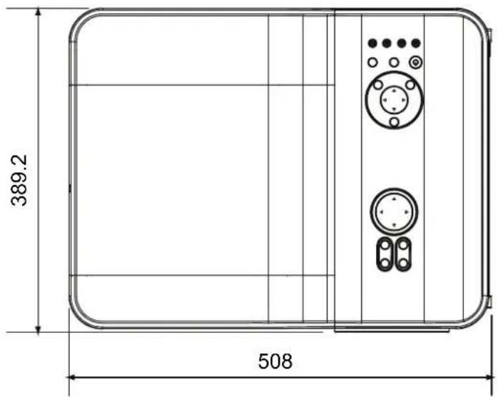
Pin Assignments of Mini D-Sub 15 Pin Input Connector

Signal Levels
Video signal: 0.7Vp-p (Analog)
Sync signal: TTL level
| PIN NUMBER | RGB SIGNAL (ANALOG) | YCBCR SIGNAL |
| 1 | Red Cr | |
| 2 Green or Sync on Green Y | ||
| 3 Blue Cb | ||
| 4 | Ground | |
| 5 | Ground | |
| 6 Red Ground Cr Ground | ||
| 7 Green Ground Y Ground | ||
| 8 Blue Ground Cb Ground | ||
| 9 No Connection | ||
| 10 Sync Signal Ground | ||
| 11 No Connection | ||
| 12 Bi-directional DATA (SDA) | ||
| 13 Horizontal Sync or Composite Sync | ||
| 14 Vertical Sync | ||
| 15 Data Clock | ||
Compatible Input Signal List
The following table shows compatible signal types, their resolution and frequency refresh rates.
Horizontal: 15kHz, 31kHz to 90 kHz
Vertical: 50 Hz to 85 Hz
| SIGNAL | RESOLUTION | H-SYNC (KHz) | V-SYNC (Hz) | RGB | DVI |
| VGA | 640X350 | 31.5 | 70.1 | ||
| VESA(DMT) | 640X350 | 37.9 | 85.1 | O | O |
| 720X350 | 31.5 | 70.0 | |||
| CGA84 | 640X400 | 31.5 | 70.1 | O | O |
| VESA(DMT) | 640X400 | 37.9 | 85.1 | O | O |
| 720X400 | 31.5 | 70.0 | |||
| VESA(DMT) | 720X400 | 37.9 | 85.0 | O | O |
| SMT | 720X400 | 31.5 | 60.0 | ||
| SMT | 640X480 | 31.5 | 60.0 | ||
| VESA | 640X480 | 37.9 | 72.8 | O | O |
| VESA(DMT) | 640X480 | 37.5 | 75.0 | O | O |
| VESA(DMT) | 640X480 | 43.3 | 85.0 | O | O |
| VESA | 800X600 | 35.2 | 56.3 | O | O |
| VESA | 800X600 | 37.9 | 60.3 | O | O |
| VESA | 800X600 | 46.9 | 75.0 | O | O |
| VESA(DMT) | 800X600 | 48.1 | 72.2 | O | O |
| VESA(DMT) | 800X600 | 53.7 | 85.1 | O | O |
| 1024X768i(*1) | 35.5 | 43.0 | O | O | |
| VESA | 1024X768 | 48.4 | 60.0 | O | O |
| VESA | 1024X768 | 56.5 | 70.1 | O | O |
| VESA(DMT) | 1024X768 | 60.0 | 75.0 | O | O |
| VESA(DMT) | 1024X768 | 68.7 | 85.0 | O | O |
| VESA(DMT) | 1152X864 | 67.5 | 75.0 | O | O |
| 1280X720 | 37.5 | 50.0 | |||
| 1280X720 | 45 | 60.0 | O | O | |
| DMT | 1280X768 | 47.4 | 60.0 | O | O |
| DMT | 1280X768 | 47.8 | 60.0 | O | O |
| DMT | 1280X768 | 60.3 | 75.0 | O | O |
| DMT | 1280X768 | 68.6 | 85.0 | O | O |
| 1280X800 | 41.2 | 50.0 | |||
| DMT | 1280X800 | 49.7 | 60.0 | O | O |
| 1280X800 | 49.6 | 60.05 | |||
| DMT | 1280X800 | 62.8 | 75.0 | O | O |
| DMT | 1280X800 | 71.6 | 85.0 | O | O |
| VESA(DMT) | 1280X960 | 60.0 | 60.0 | O | O |
| VESA(DMT) | 1280X960 | 85.9 | 85.0 | O | O |
| VESA(DMT) | 1280X1024 | 64.0 | 60.0 | O | O |
| VESA(DMT) | 1280X1024 | 80.0 | 75.0 | O | O |
| VESA(DMT) | 1280X1024 | 91.1 | 85.0 | O | O |
| 1360X768 | 47.7 | 60.0 | |||
| 1360X768 | 48.36 | 60.0 | |||
| 1360X768 | 48.36 | 60.0 | |||
| DMT | 1400X1050 | 64.7 | 60.0 | O | O |
| DMT | 1400X1050 | 65.3 | 60.0 | O | O |
| DMT | 1400X1050 | 82.3 | 75.0 | |
| CVT | 1440X900 | 55.9 | 60.0 | |
| CVT | 1440X900 | 70.6 | 75.0 | |
| CVT | 1440X900 | 80.4 | 85.0 | |
| VESA(DMT) | 1600X1200 | 75.0 | 60.0 | O |
| CVT | 1680X1050 | 65.3 | 60.0 | |
| 1035i | 1920X1035i | 33.75 | 60.0 | O |
| 1080i/50 | 1920X1080 | 28.125 | 50.0 | O |
| 1080i/60 | 1920X1080 | 33.75 | 60.0 | O |
| D-1080p/30 | 1920X1080 | 33.75 | 30.0 | O |
| D-1080p/25 | 1920X1080 | 28.125 | 25.0 | O |
| D-1080p/24 | 1920X1080 | 27.0 | 24.0 | O |
| 1080p/50 | 1920X1080 | 56.25 | 50.0 | -- |
| 1080p/60 | 1920X1080 | 67.5 | 60.0 | O |
| Apple Macintosh | 640X480 | 35.0 | 66.7 | O |
| 832X624 | 49.7 | 74.5 | O | |
| 1024X768 | 60.2 | 74.9 | O | |
| 1152X870 | 68.7 | 75.1 | O | |
| NTSC/NTSC4.43 | Chroma Sub-carrier Frequency, 3.58 MHz & 4.43 MHz | |||
| PAL | CCIR, Chroma Sub-carrier Frequency, 4.43 MHz | |||
| SECAM | CCIR Sub-carrier frequency, 4.25/4.4 MHz | |||
| SDTV | 480i | 15.8 | 60.0 | -- |
| 576i | 15.6 | 50.0 | -- | |
| EDTV | 480p | 31.5 | 60.0 | -- |
| 576p | 31.3 | 50.0 | -- | |
| HDTV | 720p | 45.0 | 60.0 | -- |
| 720p | 37.5 | 50.0 | -- | |
| 1080i | 33.8 | 60.0 | O | |
| 1080i | 28.1 | 50.0 | O | |
| 1080p | 33.8 | 60.0 | O | |
| 1080p | 56.25 | 50.0 | O | |
Note:
- An image with higher or lower resolution than the projector's native resolution (1280 x 800) will be compressed.
- Some Composite and Sync on Green signals may not be displayed correctly.
- Signals other than those specified in the table above may not be displayed correctly. If this should happen, change the refresh rate or resolution on your PC. Refer to Display Properties help section of your PC for procedures.
(*1) Not support de-interlance for interlance input source.
PC Control Codes and Cable Connections
This projector provides a function to control and monitor the projector's operations by using the RS-232C serial port.
-
Connect a RS-232C serial cross cable to SERIAL PORT IN on the projector and serial port on the PC.
-
Launch a communication software provided with PC and setup the communication condition as follows:
Baud rate : 38400 bps Parity check : none Stop bit : 1 Flow control : none Data bit : 8
Minimum delay for next command: 1ms
- Type the command for controlling the projector and then enter the "Enter" key.
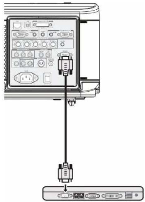
natural_image
Diagram showing connection between a device panel with an attached VGA cable (no text or labels visible)Example:
When you want to change the input to Computer 2, Type "C" "0" "6" "Enter."
The below table shows the typical command lists for controlling the projector. Please consult your local dealer for further information of another commands.
PC Control Connector (DIN-9P)
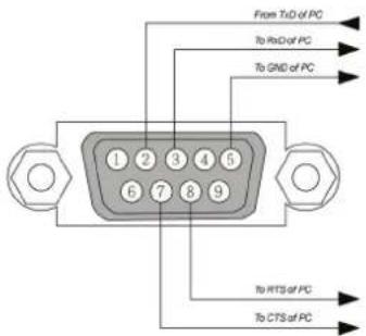
Note:
- Pin 1, 4, 6 and 9 are not used.
- Jumper "Request to Send" and "Clear to Send" together on both ends of the cable to simplify the cable connection.
- For long cables, it is recommended to set communication speed within projector menus to 9600 bps.
Control Command Diagram
The command is structured by the Header code, command code, data code and end code. Most of the commands are structured except some for the compatibility issue with other projectors.
| Header code | Command code | Data code | End code | |
| HEX | 7Eh | Command | Data | 0Dh |
| ASCII | '~' | Command | Data | CR |
Control Sequence
The projector may send a return code after it received a command. If the command isn't received correctly, the projector will not send the return code
Operation Commands
The operation commands execute the basic operation setting of this projector.
| Operation ASCII HEX | ||||||
| Power On ~ P N CR | ※ 7Eh 50h | 4Eh 0Dh | ||||
| Power Off | ~ | P | F | CR | 7Eh 50h 46h 0Dh | |
| Auto Image | ~ | A | I | CR | 7Eh 41h 49h 0Dh | |
| Input Select 1 (COMPUTER1) | ~ | S | 1 | CR | 7Eh 53h 31h 0Dh | |
| Input Select 2 (COMPUTER2) | ~ | S | 2 | CR | 7Eh 53h 32h 0Dh | |
| Input Select 3 (COMPUTER3) | ~ | S | 3 | CR | 7Eh 53h 33h 0Dh | |
| Input Select 4 (COMPONENT) | ~ | S | 4 | CR | 7Eh 53h 34h 0Dh | |
| Input Select 5 (Video) | ~ | S | 5 | CR | 7Eh 53h 35h 0Dh | |
| Input Select 6 (S-Video) | ~ | S | 6 | CR | 7Eh 53h 36h 0Dh | |
※ Power On command will not work for 1 minute after the power off command triggered.
※ CR: Carriage Return.
Remote Commands
The remote commands simulate the code send from IR remote handset.
| Button's name | ASCII | HEX | ||||
| UP arrow | ~ | r | U | CR | 7Eh 72h 55h 0Dh | |
| DOWN arrow | ~ | r | D | CR | 7Eh 72h 44h 0Dh | |
| LEFT arrow | ~ | r | L | CR | 7Eh 72h 4Ch 0Dh | |
| RIGHT arrow | ~ | r | R | CR | 7Eh 72h 52h 0Dh | |
| POWER | ~ | r | P | CR | 7Eh 72h 50h 0Dh | |
| EXIT | ~ | r | E | CR | 7Eh 72h 45h 0Dh | |
| INPUT | ~ | r | I | CR | 7Eh 72h 49h 0Dh | |
| AUTO | ~ | r | A | CR | 7Eh 72h 41h 0Dh | |
| KEYSTONE+ | ~ | r | K | CR | 7Eh 72h 4Bh 0Dh | |
| KEYSTONE- | ~ | r | J | CR | 7Eh 72h 4Ah 0Dh | |
| MENU | ~ | r | M | CR | 7Eh 72h 4Dh 0Dh | |
| STATUS | ~ | r | S | CR | 7Eh 72h 53h 0Dh | |
| MUTE | ~ | r | T | CR | 7Eh 72h 54h 0Dh | |
| ZOOM+ (Digital) | ~ | r | Z | CR | 7Eh 72h 5Ah 0Dh | |
| ZOOM- (Digital) | ~ | r | Y | CR | 7Eh 72h 59h 0Dh | |
| BLANK | ~ | r | B | CR | 7Eh 72h 42h 0Dh | |
| FREEZE | ~ | r | F | CR | 7Eh 72h 46h 0Dh | |
| VOLUME+ | ~ | r | V | CR | 7Eh 72h 56h 0Dh | |
| VOLUME- | ~ | r | W | CR | 7Eh 72h 57h 0Dh | |
| ENTER (SELECT) | ~ | r | N | CR | 7Eh 72h 4Eh 0Dh | |
| FOCUS+ | ~ | r | 0 | 0 CR | 7Eh 72h 30h 30h 0Dh | |
| FOCUS- | ~ | r | 0 | 1 CR | 7Eh 72h 30h 31h 0Dh | |
| ZOOM+ | ~ | r | 0 | 2 CR | 7Eh 72h 30h 32h 0Dh | |
| ZOOM- | ~ | r | 0 | 3 CR | 7Eh 72h 30h 33h 0Dh | |
| KEYSTONE | ~ | r | C | CR | 7Eh 72h 43h 0Dh | |
| LENS SHIFT | ~ | r | G | CR | 7Eh 72h 47h 0Dh | |
| ASPECT RATIO | ~ | r | Q | CR | 7Eh 72h 51h 0Dh | |
Set Value Command
| ITEM ASCII HEX | |||||||
| Brightness ~ s B ? CR | ※ 7Eh 73h 42h | ?h 0Dh | |||||
| Contrast | ~ | s | C | ? | CR | ||
| Color(Saturation) | ~ | s | R | ? | CR | ||
| Tint | ~ | s | N | ? | CR | ||
| Scaling ~ s A ? CR 7Eh 73h 41h | ?h 0Dh | ||||||
| Color Temperature | ~ | s | T | ? | CR | ||
| Projection Mode | ~ | s | J | ? | CR | ||
※ ? : ASCII Data
Data Range
| ITEM | Set Data Range | Source |
| Brightness 0 ~ 100(default 50) | All Source | |
| Contrast | 0 ~ 100(default 50) | All Source |
| Saturation | 0 ~ 100(default 50)※ | All Source |
| Tint | 0 ~ 100 (default 50)※ | All Source |
| Scaling | 0:4:3 1:16:9 2:15:9 3:Crop4:Letterbox5:Native6:Normal | All Source |
| Color Temperature | 0:5000K1:6500K2:7800K3:8500K4:9300K5:10500K6:High-Bright | All Source |
| Projection Mode | 0:Front 1:Rear+Ceiling 2:Rear3:Ceiling | All Source |
※ Saturation and Tint is not available when Video Type(color space) change to "RGB"
Example 1. Adjust Brightness value to 100 Send Command : \~sB100CR
Example 2. Adjust Color Temperature to Warm Send Command: \~sT2CR
Query Command
| ITEM | ASCII | HEX | ||||
| Software Version | ~ | q | V | CR | 7Eh 71h 56h 0Dh | |
| Power State | ~ | q | P | CR | 7Eh 71h 50h 0Dh | |
| Input Select | ~ | q | S | CR | 7Eh 71h 53h 0Dh | |
| Lamp Hours | ~ | q | L | CR | 7Eh 71h 4Ch 0Dh | |
| Lamp1 Hours | ~ | q | L | 1 CR | 7Eh 71h 4Ch 31h 0Dh | |
| Lamp2 Hours | ~ | q | L | 2 CR | 7Eh 71h 4Ch 32h 0Dh | |
| Brightness | ~ | q | B | CR | 7Eh 71h 42h 0Dh | |
| Contrast | ~ | q | C | CR | 7Eh 71h 43h 0Dh | |
| Saturation | ~ | q | R | CR | 7Eh 71h 52h 0Dh | |
| Tint | ~ | q | N | CR | 7Eh 71h 4Eh 0Dh | |
| Aspect Ratio | ~ | q | A | CR | 7Eh 71h 41h 0Dh | |
| Color Temperature | ~ | q | T | CR | 7Eh 71h 54h 0Dh | |
| Projection Mode | ~ | q | J | CR | 7Eh 71h 4Ah 0Dh | |
Response message
| ITEM | Response Message examples | ||||||||
| Software Version DP3650-XXXX-DPXXX | |||||||||
| Power State | On Off | ||||||||
| Input Select | Computer1 | Computer2 | Computer3 | Component | Video | S-Video | |||
| Lamp Hours | 2000,2000 | ||||||||
| Lamp1 Hours | 2000 | ||||||||
| Lamp2 Hours | 2000 | ||||||||
| Brightness | 0 ~ 100 | ||||||||
| Contrast | 0 ~ 100 | ||||||||
| Saturation | 0 ~ 100 | ||||||||
| Tint (Video) 0 ~ 100 | |||||||||
| Aspect Ratio | 4:3 | 16:9 | 15:9 | Crop | Letterbox | Native | Normal | ||
| Color Temperature | 5000K | 6500K | 7800K | 8500K | 9300K | 10500K | High-Bright | ||
| Projection Mode | Front | Rear+Ceiling | Rear | Ceiling | |||||
Example 1. Get Brightness value Send Command: \~qBCR Response: 100
Example 2. Get Color Temperature Send Command: \~qTCR Response: Warm
Screen Trigger
When the projector is powered ON the screen trigger output sends a low voltage trigger to the screen controller and the screen will go down. When the projector is powered OFF the screen trigger stops sending a low voltage trigger to the screen controller and the screen will go up.
Note:
To use this feature, you must turn on the Screen Trigger function. See Screen Trigger on page 69 for more information.
Stereo mini cable (not supplied)

Note:
Screen controllers are supplied and supported by screen manufacturers.
Note:
Do not use this jack for anything other than intended use.
Operation Using HTTP Browser
Overview
The use of HTTP server functions will allow control of the projector from a web browser without the installation of special software. Please be sure to use "Microsoft Internet Explorer 4.x" or a higher version for the web browser. (This device uses "JavaScript" and "Cookies" and the browser should be set to accept these functions. The setting method will vary depending on the version of browser. Please refer to the help files and the other information provided in your software).
Access is gained to the HTTP server functions by specifying the following address in the entry column of the URL:
http://
http://
Note:
The display or button responses can be slowed down or operation may not be accepted depending on the settings of your network. Should this happen, consult your network administrator. The projector may not respond if its buttons are repeatedly pressed in rapid intervals. Should this happen, wait a moment and repeat. If you still can't get any response, turn off and back on the projector.
Preparation Before Use
Make network connections, set up the projector and confirm that it is complete before engaging in browser operations (see Network setting on page 65 for more information).
Operation with a browser that uses a proxy server may not be possible depending on the type of proxy server and the setting method. Although the type of proxy server will be a factor, it is possible that items that have actually been set will not be displayed depending on the effectiveness of the cache, and the contents set from the browser may not be reflected in operation. It is recommended that a proxy server not be used unless it is unavoidable.
Handling of the Address for Operation by Using a Browser
Regarding the actual address that is entered for the address or entered to the URL column when operation of the projector is via a browser, the host name can be used as it is when the host name corresponding to the IP address of the projector has been registered to the domain name server by a network administrator, or the host name corresponding to the IP address of the projector has been set in the "HOSTS" file of the computer being used.
Example 1:
When the IP address of the projector is 192.168.73.1, access is gained to the HTTP server functions by specifying http://192.168.73.1/index.html for the address or the entry column of the URL.
Configuring Network Settings
The Network Settings screen is displayed as follows:
http://
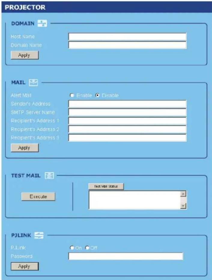
DOMAIN
Host Name: Type in a hostname. Up to 60 alphanumeric characters can be used.
Domain Name: Type in domain name of the network connected to the projector. Up to 60 alphanumeric characters can be used.
Apply: Click to reflect the entries.
Alert Mail: Click "Enable" to enable Alert Mail feature. This option notifies your computer of an error message via e-mail when using wired LAN. The error message will be notified when the projector lamp has reached the end of its usable life or an error occurs in the projector.
Sender's Address: Specify the sender's address. Up to 60 alphanumeric and symbols, characters can be used.
SMTP Server Name: Type in the SMTP server name to be connected to the projector. Up to 60 alphanumeric characters can be used.
Recipient's Address 1 to 3: Type in your recipient's address. Up to 60 alphanumeric and symbols characters can be used.
Apply: Click to apply the settings.
TEST MAIL
Send a test mail to check if your settings are correct. Click to "Execute" to enable this feature.
Test Mail Status Button: Click to display the test result.
Sample of a message sent from the projector:
Projector Name: X X X X
Lamp 1 or 2 Hours Used: xxxx [H]
The lamp is at the end of its usable life. Please replace the lamp.
Note:
If you entered an incorrect address in a test, you may not receive an Alert mail. Should this happen, check if the Recipient's Address is correctly set.
Unless any one of the [Sender's Address], [SMTP Server's Name] or [Recipient's Address 1-3] is selected, [Test Mail] is not available.
PJLINK
This option allows you to set a password when you use the PJLink feature.
On/Off: Enable or disable the password.
Password: Enter a password (up to 32 characters)
Note:
PJLink is a standardization of protocol used for controlling projectors of different manufacturers. This standard protocol is established by Japan Business Machine and Information System Industries Association (JBMIA) in 2005.
The projector supports all the commands of PJLink Class 1.
| PROJECTOR INPUT | PJLINK INPUT | PARAMETER |
| Computer 1 RGB 1 11 | ||
| Computer 2 RGB 2 12 | ||
| Video | VIDEO | 1 |
| S-Video | VIDEO | 2 |
| Component | VIDEO | 3 23 |
| Computer 3 DIGITAL 1 31 |

21 22
Structure of the HTTP Server
Once the projector is connected to a network and configured correctly, the following screen is displayed through the web browser.
http://
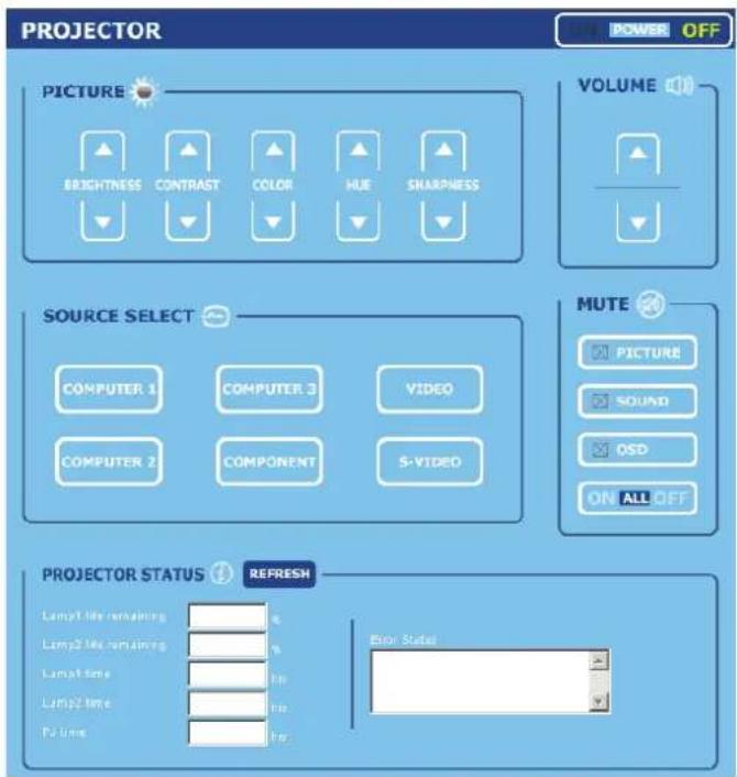
| FUNCTION SETTING DESCRIPTION | ||
| POWER Panel ON | OFF | This controls the power to the projector |
| VOLUME Panel ▲ - | Increases the volume adjustment value▼ – Decreases the volume adjustment value | This controls the volume of the projector |
| MUTE Panel PICTURE | ON – Mutes the videoPICTURE OFF – Cancels the video mutingSOUND ON – Mutes the audioSOUND OFF – Cancels the audio mutingOSD ON – Mutes the on-screen displayOSD OFF – Cancels the muting of the on-screen displayALL ON – Mutes each of the video, audio, and on-screen display functionsALL OFF – Cancels the muting of each of the video, audio, and on-screen display functions | This controls the mute functions of the projector |
| PICTURE Panel | BRIGHTNESS ▲▼ – Increases or decreases the brightness adjustment valueCONTRAST ▲▼ – Increases or decreases the contrast adjustment valueCOLOR ▲▼ – Increases or decreases the color adjustment valueTINT ▲▼ – Increases or decreases the hue adjustment valueSHARPNESS ▲▼ – Increases or decreases the sharpness adjustment value | Controls the video adjustments of the projector |
| SOURCE SELECT Panel | COMPUTER1 – Switches to the COMPUTER 1 IN connectorCOMPUTER2 – Switches to the COMPUTER 2 IN connectorCOMPUTER3 – Switches to the COMPUTER 3 IN connectorCOMPONENT – Switches to the COMPONENT IN connectorsVIDEO – Switches to the VIDEO IN connectorS-VIDEO – Switches to the S-VIDEO IN connector | This switches the input connector of the projector |
| PROJECTOR STATUS Panel | Refresh – Updates the panel with the latest information availableLamp1 life remaining – Displays the remaining life of Lamp 1 as a percentageLamp2 life remaining – Displays the remaining life of Lamp 2 as a percentageLamp1 time – Displays the number of hours Lamp 1 has been usedLamp2 time – Displays the number of hours Lamp 2 has been usedPJ time – Displays the number of hours the project has been usedError Status – Displays the status of errors occurring within the projector | This displays the status of selected projector functions |
Note:
The functions that can be controlled will vary depending on the signal being input to the projector (see Selecting an Input Source on page 23 for more information).
FCC Warning
This equipment has been tested and found to comply with the limits for a Class B digital device pursuant to Part 15 of the FCC Rules. These limits are designed to provide reasonable protection against harmful interference when the equipment is operated in a commercial environment.
This equipment generates, uses, and can radiate radio frequency energy and, if not installed and used in accordance with the instruction manual, may cause harmful interference to radio communications.
Operation of this equipment in a residential area is likely to cause harmful interference in which case the user will be required to correct the interference at his/her own expense.
Changes or modifications not expressly approved by the parties responsible for compliance could void the user's authority to operate the equipment.
Canada
This class B digital apparatus complies with Canadian IECS-003.
Safety Certifications
UL (file no: E134786) (UL60950-1/CSA60950-1), EMC, CE, and CCC.
EN 55022 Warning
This is a Class B product. In a domestic environment, it may cause radio interference, in which case the user may be required to take adequate measures. The typical use is in a conference room, meeting room, or auditorium.

- Disclaimer
- Trademark Recognition
- Important Safety Information
- Important:
- Symbols Used
- Note:
- Caution:
- Warning:
- Remote Control
- General Safety Information
- Power Safety
- Replacing the Lamp
- Important Recycle Instructions:
- Cleaning the Projector
- Regulatory Warnings
- Symbol Explanations
- Projector Installation Notice
- Main Features
- About this manual
- Table of Contents
- INTRODUCTION....1
- SETUP AND OPERATION....10
- PROJECTING AN IMAGE (BASIC OPERATION)....21
- CONVENIENT FEATURES....33
- MAINTENANCE....77
- APPENDIX....84
- SPECIFICATIONS....88
- REGULATORY COMPLIANCE....104
- INTRODUCTION
- Packing Checklist
- Views of Projector Parts
- Top Features
- Remote Control Parts
- Remote Control Operating Range
- Projector and Remote Control Buttons
- Inserting the Remote Control Batteries
- Installing or Removing the Optional Lens
- Removing the Existing Lens From the Projector
- Installing the New Lens
- Throw Distance and Screen Size
- Installing the Optional Color Wheel
- Making Connections
- Connecting Your PC or Macintosh Computer
- Connecting an External Monitor
- Connecting Your DVD Player with Component Output
- Connecting Your VCR or Laser Disc Player
- PROJECTING AN IMAGE (BASIC OPERATION)
- Turning on the Projector
- Note on Startup Screen (Menu Language Select screen)
- Selecting an Input Source
- Adjusting the Picture Position and Picture Size
- Adjusting Picture Position Manually
- Lens Shift Adjustable Range
- From the Remote Control Unit
- Adjusting the Projector Level
- Optimizing an RGB Image Automatically
- Adjusting Volume Up and Down
- Turning off the Projector
- About Direct Power Off
- After Use
- Turning Off the Image and Sound
- Freezing a Picture
- Adjusting the Focus/Zoom Manually
- Changing Lamp Mode
- Getting Information
- Adjusting Position/Total Dots/Fine Sync
- 1.
- 2.
- 3.
- 4.
- Correcting Keystone by Using the Remote Control
- Preventing the Unauthorized Use of the Projector
- Locking the Projector
- Unlocking the Projector
- Using the Physical Lock
- Using the Kensington Lock
- Using the Menus
- Navigating the OSD
- Menu Tree
- Menu Elements
- Input Menu Descriptions and Functions
- Adjust Menu Descriptions and Functions
- Image menu
- Image options menu
- Screen
- Overscan
- Video menu
- 3D Y/C separation
- Progressive
- Color matrix
- Film
- Detail Setting Menu Descriptions and Functions
- Basic
- Gamma
- White balance
- Color correction
- Setting Menu Descriptions and Functions
- Language
- Installation
- Communication speed
- Background
- Network setting
- Option
- Power management
- Screen trigger
- Fan control
- Message
- Filter warning
- Search mode
- Information Menu Descriptions and Functions
- Usage time
- Input
- Network
- Version
- Reset Menu Descriptions and Functions
- Cleaning the Cabinet
- Cleaning the Lens
- Cleaning the Filters
- Please clean filter.
- Replacing the Lamps
- The lamp has reached the end of its usable life. Please replace the lamp.
- If a lamp explodes, the following safety precautions should be taken:
- Resetting the Lamp Time Counter
- Troubleshooting
- Indicator Messages
- Common Problems and Solutions
- Tips for Troubleshooting
- Image Problems
- Problem: No image appears on the screen
- Problem: The image is blurred
- Problem: The image is wider at the top or bottom (trapezoid effect)
- Problem: The image is reversed or upside down
- Problem: The image is streaked
- Problem: The image is flat with no contrast
- Problem: The color of the projected image does not match the source image.
- Lamp Problems
- Problem: There is no light from the projector
- Problem: The lamp goes off
- Remote Control Problems
- Problem: The projector does not respond to the remote control
- Audio Problems
- Problem: There is no sound
- Problem: The sound is distorted
- Having the Projector Serviced
- Projector Specifications
- Optional Parts
- Pin Assignments of Mini D-Sub 15 Pin Input Connector
- Compatible Input Signal List
- PC Control Codes and Cable Connections
- Example:
- PC Control Connector (DIN-9P)
- Control Command Diagram
- Control Sequence
- Operation Commands
- Remote Commands
- Operation Using HTTP Browser
- Overview
- Preparation Before Use
- Handling of the Address for Operation by Using a Browser
- Example 1:
- Configuring Network Settings
- DOMAIN
- TEST MAIL
- PJLINK
- Structure of the HTTP Server
- FCC Warning
- Canada
- Safety Certifications
- EN 55022 Warning
Brand : VIVITEK
Model : D6010
Category : Video projector