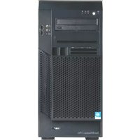
IntelliStation Z Pro - Desktop computer IBM - Free user manual and instructions
Find the device manual for free IntelliStation Z Pro IBM in PDF.


| Product type | Workstation / Desktop computer |
| Brand | IBM |
| Model | IntelliStation Z Pro |
| Processor | Intel Xeon (single or dual) |
| RAM (Memory) | Up to 4 GB (DDR SDRAM) |
| Internal storage | SCSI hard drive (up to 72 GB) |
| Graphics card | NVIDIA Quadro or ATI FireGL |
| Dimensions (H x W x D) | 200 x 450 x 500 mm |
| Weight | Approximately 15 kg |
| Power supply | 400 Watts |
| Connectivity | 2x USB 1.1, 1x VGA, 1x Ethernet 10/100, serial and parallel ports |
| Operating system | Windows 2000 / Windows XP Professional (pre-installed) |
| Main functions | Workstation for 3D design, CAD/CAM, graphic rendering |
| Maintenance and cleaning | Regular dusting with a soft cloth; avoid moisture |
| Security | Kensington lock, BIOS password, anti-theft support |
| Spare parts and repairability | Hard drive, memory, graphics card, power supply replaceable; access via side panel |
Frequently Asked Questions - IntelliStation Z Pro IBM
User questions about IntelliStation Z Pro IBM
0 question about this device. Answer the ones you know or ask your own.
Ask a new question about this device
Download the instructions for your Desktop computer in PDF format for free! Find your manual IntelliStation Z Pro - IBM and take your electronic device back in hand. On this page are published all the documents necessary for the use of your device. IntelliStation Z Pro by IBM.
USER MANUAL IntelliStation Z Pro IBM
Hardware Maintenance Manual and TroubleshootingGuide
Hardware Maintenance Manual and TroubleshootingGuide
Notes
- Before using this information and the product it supports, read the general information in Appendix B, "Safety Information, on page 127, and Appendix C, "Notices," on page 161.
- The most recent version of this document is available at http://www.ibm.com/pc/support.
Aboutthisdocument
This document contains basic configuration information, diagnostic information, error codes, error messages, service information, and a symptom-to-FRU index for the IBM ® IntelliStation ® Z Pro Types 6223 and 6227 computers.
Important: The field replaceable unit (FRU) procedures in this document are intended for trained servicers who are familiar with IBM products. Customer replacement units (CRUs) can be replaced by the customer. See Chapter 7, "Parts listing Types 6223 and 6227," on page 115, to determine if the component being replaced is a FRU or a CRU. Before servicing an IBM product, be sure to read Appendix B, "Safety information," on page 127.
Important safety information
Be sure to read all caution and danger statements in this book before performing any of the instructions.
WARNING: Handling the cord on this product or cords associated with accessories sold with this product, will expose you to lead, a chemical known to the State of California to cause cancer, and birth defects or other reproductive harm. Wash handsafterhandling.
You can download the most current diagnostic, BIOS flash, and device-driver files from http://www.ibm.com/support.
Contents
Aboutthisdocument.
Important safety information. . . . . . . . . . . . . . . . . . . . . . . . i i i
Online support. i v
Chapter1.Introduction. 1
Related documentation. 1
Notices and statements used in this document. 2
Features and specifications. 3
What your computer offers. 4
Reliability, availability, and serviceability features. 4
Controls, LEDs, and connectors. 6
Turning on the computer 8
Turning off the computer 9
Chapter 2. Configuring the computer ..... 11
Starting the Configuration/Setup Utility program ..... 1 2
Chapter3.Diagnostics 1 3
General checkout 1 3
Diagnostic tools overview 1 4
Power-on self-test (POST). 1 5
POST beep codes 1 5
POST error messages 16
Diagnostic programs and error messages . . . . . . . . . . . . . . . 1 6
Text messages. 1 6
Starting the diagnostic programs and viewing the test log . . . . . . . . 1 7
Small computer system interface (SCSI) messages 17
PC-Doctor for Windows. 1 8
Updating (flash-updating) the BIOS code on the computer . . . . . . . . 1 8
Recovering from a POST/BIOS update failure . . . . . . . . . . . . . 1 9
Erasing a lost or forgotten password (clearing CMOS) 20
Replacing the battery 2 1
Power checkout 2 2
Chapter4.Installingoptions 2 3
Installation guidelines 2 3
System reliability considerations 2 3
Handling static-sensitive devices . . . . . . . . . . . . . . . . . . 2 3
Installing options in your computer. 2 4
Major components of your computer . . . . . . . . . . . . . . . . 2 4
Removing the side cover 2 5
Removing the bezel 2 6
Installing an adapter. 2 6
Cabling an optional SCSI adapter . . . . . . . . . . . . . . . . . . 3 0
Installing a drive 3 1
Installing memory modules 4 1
Installing a second microprocessor 4 4
Installing an external SCSI cable 48
Installing a security rope clip . . . . . . . . . . . . . . . . . . . . 4 9
Replacing the bezel 50
Replacing the side cover 5 1
Connecting external options. 5 2
Input/output connectors. 5 3
Audio connectors. 5 4
Auxiliary-device (pointing-device) connector. 5 4
Ethernet (RJ-45) connector. 5 4
IEEE 1394A (FireWire) connector . . . . . . . . . . . . . . . . . . . . . 5 5
Keyboard connector. 5 5
Parallel connector 5 5
Serial connectors. 5 6
Ultra320 SCSI connector. 5 6
Universal Serial Bus connectors . . . . . . . . . . . . . . . . . . 5 7
Video connector 57
Chapter5.Fieldreplaceableunits. 5 9
Microprocessor and heat sink. 60
CD-ROM drive 6 1
Non-hot swap power supply. 6 2
Rear-adapter retention bracket 6 3
I/O card retainer. 6 4
Front (microprocessor) fan 6 5
Hard drive fan. 6 6
Power/LED switch assembly 6 8
Card/bracket assembly 6 9
Speaker. 70
System board. 7 1
System board option connectors . . . . . . . . . . . . . . . . . . 7 1
System board internal connectors 7 2
System board external connectors. 7 3
System board error LEDs 7 4
System board jumpers and switches 7 5
Removing the system board. 7 6
Top/side cover. 7 8
Bezel-release latch. 7 9
Handle assembly. 8 1
Chapter6.Symptom-to-FRUindex. 83
Beep symptoms 8 3
No-beep symptoms 8 5
POST error codes. 8 5
Diagnostic error codes 90
Diagnostic error LEDs 9 5
Error symptoms 9 5
Hot-swap power-supply LED errors . . . . . . . . . . . . . . . . . 1 0 3
Service processor error codes 104
SCSI error codes. 104
ServeRAID error codes 105
POST(ISPR) error procedures 107
Temperature error messages 109
Fan error messages. 109
Power error messages. 11 0
System shutdown 11 0
Voltage-related system shutdown. 110
Temperature-related system shutdown . . . . . . . . . . . . . . . . . 111
Hard disk drive checkout . . . . . . . . . . . . . . . . . . . . . . . . 111
Host built-in self test (BIST) 11 2
Bus fault messages. 112
Undetermined problems 113
Problem determination tips 114
Chapter7.PartslistingTypes6223and6227. 1 1 5
System. 1 1 6
System replaceable units. 1 1 7
Recovery CD (Windows XP) 1 2 1
Keyboards (CRUs) 1 2 1
Power cords (CRUs) 1 2 2
AppendixA.Gettinghelpandtechnicalassistance. 1 2 5
Before you call . . . . . . . . . . . . . . . . . . . . . . . . . . 1 2 5
Using the documentation. 1 2 5
Getting help and information from the World Wide Web . . . . . . . . 1 2 6
Software service and support 1 2 6
Hardware service and support . . . . . . . . . . . . . . . . . . . . 1 2 6
AppendixB.Safetyinformation 1 2 7
General safety 1 2 7
Electrical safety 1 2 8
Safety inspection guide . . . . . . . . . . . . . . . . . . . . . . . 1 2 9
Handling electrostatic discharge-sensitive devices 1 3 0
Grounding requirements. 1 3 0
Safety notices (multilingual translations) 1 3 1
AppendixC.Notices. 1 6 1
Edition notice . . . . . . . . . . . . . . . . . . . . . . . . . . . . . 1 6 1
Trademarks. 1 6 2
Important notes 1 6 3
Product recycling and disposal 1 6 3
Battery return program 1 6 4
Electronic emission notices . . . . . . . . . . . . . . . . . . . . . . 1 6 4
Federal Communications Commission (FCC) statement 1 6 4
Industry Canada Class B emission compliance statement. ..... 1 6 5
European Union EMC Directive conformance statement ..... 1 6 5
Japanese Voluntary Control Council for Interference (VCCI) statement 165
Index. 1 6 7
Chapter1.Introduction
The IBM IntelliStation Z Pro Types 6223 and 6227 incorporates many of the latest advances in computing technology and can be expanded and upgraded as your needs change.
You can obtain up-to-date information about your computer and other IBM computer products at http://www.ibm.com/pc/intellistation.
Note: The illustrations in this document might differ slightly from your hardware.
Relateddocumentation
This Hardware Maintenance Manual and Troubleshooting Guide is provided in Portable Document Format (PDF). It contains information to help a user solve problems or to provide helpful information to a service technician. The following documents also come with the computer:
•InstallationGuide
This printed document contains setup and installation instructions.
-User'sGuide
This document is in Portable Document Format (PDF) on the IBM IntelliStation DocumentationCD. It contains detailed information about your computer and how to use and configure the functions of the computer.
•SafetyInformation
This document is in Portable Document Format (PDF) on the IBM IntelliStation DocumentationCD. It contains translated caution and danger statements. Each caution and danger statement that appears in the documentation has a number that you can use to locate the corresponding statement in your language in the SafetyInformationdocument.
•AdaptecSCSIdocumentation
This document is in PDF on the DeviceDriversCD. It contains information and instructions for installing and configuring small computer system interface (SCSI) device drivers and devices.
- Readme files on the DeviceDriversCD
Several readme files on this CD contain information about the preinstalled device drivers. Other readme files on this CD contain information about the various adapters and devices that might be installed in or attached to your computer.
•IBM IntelliStationDocumentationCD
This CD contains all of the IBM IntelliStation Z Pro Type 6223 documents in Portable Document Format (PDF).
Depending on your computer model, additional documentation might be included on the IBM IntelliStationDocumentationCD.
Your computer might have features that are not described in the documentation that you received with the computer. The documentation might be updated occasionally to include information about those features, or technical updates might be available to provide additional information that is not included in your computer documentation. These updates are available from the IBM Web site. Complete the following steps to check for updated documentation and technical updates:
- Go to http://www.ibm.com/pc/support/.
- In the Learnsection, click Publications.
- On the "Publications" page, in the Brand field, select IntelliStation.
- In the Familyfield, select IntelliStationZPro.
- Click Continue.
Noticesandstatementsusedinthisdocument
The caution and danger statements that appear in this document are also in the multilingual Safety Information document, which is on the IBM IntelliStation DocumentationCD. Each statement is numbered for reference to the corresponding statement in the SafetyInformationdocument.
The following notices and statements are used in this document:
- Notes: These notices provide important tips, guidance, or advice.
- Important: These notices provide information or advice that might help you avoid inconvenient or problem situations.
- Attention: These notices indicate potential damage to programs, devices, or data. An attention notice is placed just before the instruction or situation in which damage could occur.
- Caution: These statements indicate situations that can be potentially hazardous to you. A caution statement is placed just before the description of a potentially hazardous procedure step or situation.
- Danger: These statements indicate situations that can be potentially lethal or extremely hazardous to you. A danger statement is placed just before the description of a potentially lethal or extremely hazardous procedure step or situation.
Featuresandspecifications
The following table provides a summary of the features and specifications of your computer. Depending on your model, some features might not be available, or some specifications might not apply.
Table1.Featuresandspecifications
| Microprocessor:•Supports up to two Intel® Xeon microprocessors•1 MB Level-2 cache•800 MHz front-side bus (FSB)Memory:•Minimum: 512 MB•Maximum: 8 GB (depending on your configuration)•Type: PC2-3200 double-data-rate 2 (DDR2) registered•Connectors: six dual inline memory module (DIMM) connectorsInternalDrives:•Hard disk drive: SCSI or Serial ATA (SATA)•One of the following optical drives:– CD-ROM: IDE– DVD/CD-RW combo: IDE– CD-RW: IDEExpansionbays:•Three slim-high 3.5-inch drive bays (one hard disk drive installed in some models)•Two half-high 5.25-inch bays (optical drive installed in one bay)•One slim-high 3.5-inch removable-media or hard disk drive bayPCIexpansionslots:•Two 33 MHz/32-bit PCI, 5.0 V signaling•Two 100 MHz/64-bit PCI-X slots, 3.3 V signaling•One 133 MHz/64-bit PCI-X slot, 3.3 V signaling•One PCI Express x16 slotPowersupply:One 530 watts (115-230 V ac)Cooling:Four speed-controlled fans | Integratedfunctions:•Broadcom 5721 10/100/1000 Ethernet controller with RJ-45 Ethernet connector•Integrated RAID capability•Integrated SCSI controller with two Ultra320 SCSI ports (one internal, one optional external)•Two serial ports•One parallel port•Dual port Serial ATA controller•Two IEEE 1394A (FireWire) ports (four-pin on front, six-pin on rear)•Six Universal Serial Bus (USB) ports (two on front and four on rear)•Keyboard port•Mouse port•Audio ports– Line out (front and rear)– Mic (front and rear)– Line in (rear only)•ATA-100 single-channel IDE controllerVideoadapter:(depending on your model)•NVIDIA Quadro NVS 280 (DMS-59), PCI Express x16, with 64 MB DDR synchronous dynamic random access memory (SDRAM) video memory and dual analog connectors (or dual digital monitor capability with the purchase of an additional pigtail cable)•NVIDIA Quadro FX 1300 (DVI-I), PCI Express x16, with 128 MB DDR SDRAM video memory with dual DVI-I connectors•NVIDIA Quadro FX 3400 (DVI-I), PCI Express x16, with 256 MB GDDR3 SDRAM video memory with dual DVI-I connectorsElectricalinput:•Sine-wave input (50 or 60 Hz) required•Input voltage and frequency ranges automatically selected•Input voltage low range:– Minimum: 90 V ac– Maximum: 137 V ac•Input voltage high range:– Minimum: 180 V ac– Maximum: 265 V ac•Input kilovolt-amperes (kVA) approximately:– Minimum: 0.24 kVA– Maximum: 0.86 kVA | Heatoutput:Approximate heat output in British thermal units (Btu) per hour:•Minimum configuration: 787 Btu (230 watts)•Maximum configuration: 2780 Btu (815 watts)Environment:•Air temperature:– Computer on: 10irc to 35ircC ( 50irc to 95ircF ).Altitude: 0 to 2134 m (7000 ft)– Computer off: -40irc to +60ircC ( -40irc to 140ircF ). Maximum altitude: 2133 m (7000 ft)•Humidity (operating and storage): 8% to 80%Acousticalnoiseemissions:•Sound power, idle: 5.0 bel•Sound power, operating: 5.3 belSize:•Height: 469.9 mm (18.5 in.)•Depth: 495.3 mm (19.5 in.)•Width: 215.9 mm (8.5 in.)•Weight: 16.2 kg (36 lb) to 22.6 kg (50 lb) depending upon configurationNotes:1. Power consumption and heat output vary depending on the number and type of optional features installed and the power-management optional features in use.2. These levels were measured in controlled acoustical environments according to the procedures specified by the American National Standards Institute (ANSI) S12.10 and ISO 7779 and are reported in accordance with ISO 9296. Actual sound-pressure levels in a given location might exceed the average values stated because of room reflections and other nearby noise sources. The declared sound-power levels indicate an upper limit, below which a large number of computers will operate. |
Whatyourcomputeroffers
Your computer uses the following features and technologies:
•Multiplemicroprocessorcapability
Your computer can be upgraded to a symmetric multiprocessing (SMP) computer through a microprocessor upgrade.
•PCIExpress,x16,graphics
Your computer comes with a graphics adapter installed in the PCI Express x16 slot (slot 1). This high-performance adapter supports high resolutions and includes many performance-enhancing features for your operating-system environment.
•Largesystem-memorycapacity
Your computer supports up to 8 GB (when using 2 GB double-rank DIMMs) of system memory. The memory controller provides error correcting code (ECC) support for up to four industry-standard PC2-3200, 1.8 V, 240-pin, 400 megahertz (MHz) (bus speed) registered, double-data-rate (DDR), synchronous dynamic random access memory (SDRAM) dual inline memory modules (DIMMs).
Note: The Microsoft Windows XP operating systems recognize and support a maximum of 4 GB of system memory.
•Systems-managementcapabilities
Your computer comes with features that a network administrator or server can use to remotely manage and control the computer. These features include Wake on LAN, Remote Administration, and IBM Director Agent.
The memory controller in your computer provides Chipkill memory protection if the DIMMs are 1 GB or larger. Chipkill memory protection is a technology that protects the computer from a single chip failure on a DIMM.
•Integratednetworksupport
Your computer comes with an integrated Ethernet controller, which supports connection to a 10-Mbps, 100-Mbps, or 1-Gbps network. The controller supports Wake on LAN technology.
Reliability, availability, and serviceability features
Three important computer design features are reliability, availability, and serviceability (RAS). The RAS features help to ensure the integrity of the data that is stored in your computer, the availability of the computer when you need it, and the ease with which you can diagnose and repair problems.
Your computer has the following RAS features:
•24 hours a day, 7 days a week 1 customer support
•3-year limited warranty
- Advanced Configuration and Power Interface (ACPI)
•Auto-restart initial program load (IPL) power supply
•Automatic computer restart after a power failure
•Automatic error retry or recovery
- Boot-block recovery
•Built-in, menu-driven configuration and setup programs
•Built-in, menu-driven SCSI configuration programs (some models)
•Diagnostic programs
•Cooling fans with speed-sensing capability
- Error codes and messages
- Error correcting code (ECC) double-data-rate (DDR) synchronous dynamic random access memory (SDRAM) with serial presence detect (SPD)
- Hard disk drive partition-based diagnostic programs
•Integrated Ethernet controller
•Monitoring support for temperatures, voltages, and fan speed
•Power-on self-test (POST)
- Self-Monitoring Analysis and Reporting Technology (SMART) on hard disk drives for early prediction of failures
- Read-only memory (ROM) checksums
- Upgradeable basic input/output system (BIOS) and POST code
- Wake on LAN capability
Controls, LEDs, and connectors
The following illustration shows the controls, LEDs, and front connectors on the IntelliStation Z Pro Types 6223 and 6227 computers. See "input/output connectors" on page 53 for an illustration and description of the connectors on the rear of the computer.
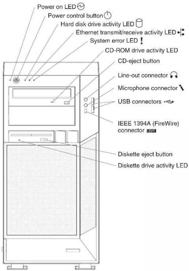
Power-onLED
When this LED is lit and not flashing, it indicates that the computer is turned on. When this LED is flashing, it indicates that the computer is off and still connected to an ac power source (standby mode).
Power-controlbutton
Press this button to turn the computer on or off.
HarddiskdriveactivityLED
When this LED is lit, it indicates that the hard disk drive is in use.
Ethernettransmit/receiveactivityLED
When this LED is flickering, it indicates that there is activity between the computer and the network. There are two of these LEDs, one on the front and one on the rear of the computer.
EthernetlinkstatusLED
When this LED is lit, it indicates that there is an active connection on the Ethernet port. This LED is located on the rear of the computer.
System-errorLED
When this amber LED is lit, it indicates that a system error has occurred. An LED on the system board is also lit to help isolate the error.
CD-ROMdriveactivityLED
When this LED is lit, it indicates that the CD-ROM drive is in use.
CD-ejectbutton
Press this button to insert a CD into or remove a CD from the CD-ROM drive.
Lineoutconnector(green)
Use this connector to send audio signals from the computer to external devices, such as speakers with built-in amplifiers, headphones, multimedia keyboards, or the audio line-in jack on a stereo system.
Micconnector(pink)
Use this connector to connect a microphone to your computer when you want to record voices or other sounds on the hard disk. You can also use this connector (and a microphone) with speech recognition software.
USBconnectors
Use these connectors to connect USB devices to your computer, using redundant Plug and Play technology.
IEEE1394A(FireWire)connectors
Use these connectors (four-pin on the front and six-pin on the rear) to connect FireWire devices, such as digital video cameras and external hard disk drives.
Diskette-ejectbutton
Press this button to release a diskette from the diskette drive.
DiskettedriveactivityLED
When this LED is lit, it indicates that the diskette drive is in use.
Turningonthecomputer
Note: When you connect the power cord to the computer and an ac power source, the power-supply fan will run and continue to run when the computer is in standby mode to provide cooling to the power supply.
When the computer is connected to an ac power source but is not turned on, the operating system does not run, and all core logic is shut down; however, the computer can respond to remote requests to turn on the computer. The power-on LED flashes to indicate that the computer is connected to an ac power source but is not turned on.
Notes:
- Turn on all external devices, such as the monitor, before turning on the computer.
- The power-on LED on the front of the computer is lit when the computer is on and while it is being turned on.
Approximately 20 seconds after the computer is connected to ac power, the power-control button becomes active, and you can turn on the computer and start the operating system by pressing the power-control button. The computer can also be turned on in any of the following ways:
- If a power failure occurs while the computer is turned on, the computer will restart automatically when power is restored.
- When you connect the computer to power for the first time, the Wake on LAN feature can turn on the computer. If the computer was previously turned on, it must be turned off correctly for the Wake on LAN feature to turn on the computer.
What you see and hear when you start the computer depends on the features that are installed and the settings in the Configuration/Setup Utility program.
If the power-on self-test (POST) detects a problem, there might be a series of beeps or no beep, and a numeric error message might appear on the screen. Write down any beep series and error code numbers with descriptions, and then see Chapter 6, "Symptom-to-FRU index," on page 83 for an explanation of the error codes.
Turningoffthecomputer
Note: When you connect the power cord to the computer and an ac power source, the power-supply fan will run and continue to run when the computer is in standby mode to provide cooling to the power supply.
When you turn off the computer and leave it connected to ac power, the computer can respond to requests, such as a remote request to turn on the computer. To remove all power from the computer, you must disconnect it from the power source.
Some operating systems require an orderly shutdown before you turn off the computer. See your operating-system documentation for information about shutting down the operating system.
Statement5:


CAUTION:
The power control button on the device and the powers switch on the power supply don't turn off the electrical currents supplied to the device. The device also might have more than one power cord. Toremove electrical current from the device, ensure that all power cords are disconnected from the power source.


2
1
The computer can be turned off in any of the following ways:
- You can turn off the computer through the operating system. If this feature is supported by your operating system, it will turn off the computer after performing an orderly shutdown of the operating system.
If you are using the preinstalled Microsoft Windows XP operating system, complete the following steps to shut down the operating system and computer:
- Save and close all files that you are working with.
- Close all open applications.
- Click Start.
- Click Turn Off Computer; then, click Turn Off to confirm.
If you are using the preinstalled Red Hat Linux operating system, complete the following steps to shut down the operating system and computer:
- Save and close all files with which you are working.
- Close all open applications.
- Click Red Hat Linux Main Menu Button → Logout → Shutdown.
- Click OK to confirm.
- You can press the power-control button on the front of the computer. It will turn off the computer after performing an orderly shutdown of the operating system, if this feature is supported by your operating system.
Note: After turning off the computer, wait at least 5 seconds before you press the power-control button to turn on the computer again.
- You can press and hold the power-control button for more than 4 seconds to cause an immediate shutdown of the computer. You can use this feature to turn off the computer if the operating system stops functioning.
Chapter2.Configuringthecomputer
Detailed information about configuring the computer is in the IBM IntelliStation Z Pro User'sGuideon the IBM DocumentationCD.
The latest information about these programs and the most recent device-driver files are available at http://www.ibm.com/support.
The following configuration programs are available to configure your computer:
- Configuration/SetupUtilityprogram
The Configuration/Setup Utility program is part of the basic input/output system (BIOS) code in your computer. You can use this program to configure serial- and parallel-connector assignments, change interrupt request (IRQ) settings, change the drive startup sequence, set the date and time, and set passwords, and set the chassis-intrusion detector. For more information on how to start this utility, see "Starting the Configuration/Setup Utility program" on page 12. For detailed information, see the User'sGuide.
- BootMenuprogram
The Boot Menu program is part of the BIOS code in your computer. Use it to temporarily assign a device to be first in the startup sequence, overriding the startup sequence that is set in the Configuration/Setup Utility program.
•BroadcomNetXtremeGigabitEthernetBootAgent
The Broadcom NetXtreme Gigabit Ethernet Boot Agent is part of the BIOS code in your computer. You can use it to configure the network as a startable device, and you can customize where the network startup option appears in your startup sequence. You enable and disable the Broadcom NetXtreme Gigabit Ethernet Boot Agent from the Configuration/Setup Utility program.
-Adaptec HostRAID TM configurationprograms
- AdaptecRAIDConfigurationUtilityprograms(forSerialATARAID)
Use the Array Configuration Utility within the Adaptec RAID Configuration Utility programs to configure the integrated Serial ATA (SATA) controller with integrated RAID and the devices that are attached to it.
- SCSISelectUtilityprogram(forSCSIRAID)
Use the SCSI HostRAID feature of the SCSISelect Utility program to configure the integrated SCSI controller with integrated RAID and the devices that are attached to it.
- ServeRAIDManager
ServeRAID Manager is available as a stand-alone program and as an IBM Director extension. If a ServeRAID controller is installed in your computer, use ServeRAID Manager to define and configure your disk-array subsystem before you install your operating system.
•Ethernetcontrollerconfiguration
Use this selection to configure the integrated Gigabit Ethernet controller, see
•SCSISelectUtilityprogram(somemodels)
If your computer has a SCSI adapter installed, you can configure the devices that are connected to the optional SCSI adapter. Use this program to change default values, resolve configuration conflicts, and perform a low-level format on a SCSI hard disk drive.
StartingtheConfiguration/SetupUtilityprogram
Complete the following steps to start the Configuration/Setup Utility program:
Note: When you use your computer for the first time, you might want to use the Configuration/Setup Utility menu choice LoadDefaultSetting to reset the Configuration/Setup Utility menu choices to the factory default settings, in case they were changed before you received the computer. Otherwise, some choices might not appear in the list of menu choices.
- Turn on the computer and watch the monitor screen. If the computer is already on when you start this procedure, you must shut down the operating system, turn off the computer, wait a few seconds until all in-use LEDs are turned off, and restart the computer.
- When the message Press F1 for Configuration/Setup appears on the screen during startup, press F1. (This prompt appears on the screen for only a few seconds. You must press F1 quickly.) If you have set both a user password and an administrator password, you must type the administrator password to access the full Configuration/Setup Utility menu.
- Follow the instructions on the screen.
Chapter3.Diagnostics
This chapter provides basic troubleshooting information to help solve some common problems that might occur with the computer.
If you cannot locate and correct the problem using the information in this section, see Appendix A, "Getting help and technical assistance," on page 125 for more information.
Generalcheckout
Follow the checkout procedure for diagnosing hardware problems. Review the following information before performing the checkout procedure:
- Read Appendix B, "Safety information," on page 127.
- The computer diagnostic programs are stored on the IBM Enhanced Diagnostics CD. These programs provide the primary methods of testing the major components of the computer. If you are not sure whether a problem is caused by the hardware or by the software, you can run the diagnostic programs to confirm that the hardware is working correctly.
- When you run the diagnostic programs, a single problem might cause several error messages. If you receive several error messages, correct the cause of the first error message. The other error messages might not occur the next time you run the diagnostic programs.
- Before running the diagnostic programs, you must determine whether the failing computer is part of a shared hard disk drive cluster (two or more servers sharing external storage devices). If you suspect that it is part of a cluster, you can run all diagnostic programs except the ones that test the storage unit (that is, a hard disk drive in the storage unit) or the storage adapter that is attached to the storage unit. The failing server might be part of a cluster if any of the following conditions is true:
– The customer identifies the failing server as part of a cluster.
- One or more external storage units are attached to the failing server and at least one of the attached storage units is also attached to another server or unidentifiable device.
– One or more servers are located near the failing server.
- Important:
-
For servers that are part of a shared hard disk drive cluster, run one test at a time. Do not run any suite of tests, such as "quick" or "normal" tests, because this could enable the hard disk drive diagnostic tests.
-
If more than one error code is displayed, correct the first error. The other error codes might not occur the next time you run the diagnostic programs.
-
If the server is suspended and a POST error code is displayed, see "POST error codes" on page 85.
-
If the server is suspended and no error message is displayed, see "Error symptoms" on page 95 and "Undetermined problems" on page 113.
-
For information about power-supply problems, see "Power checkout" on page 22
-
For intermittent problems, check the error log; see "Diagnostic programs and error messages" on page 16.
Complete the following steps to perform the checkout procedure:
001 ISTHESERVERPARTOFACLUSTER?
YES.Schedule maintenance for the system. Shut down all systems related to the cluster. Run the storage test.
NO.Go to step 002.
002 IFTHESERVERISNOTPARTOFACLUSTER:
- Turn off the server and all external devices.
- Check all cables and power cords.
- Set all display controls to the middle position.
- Turn on all external devices.
- Turn on the server.
- Record any POST error messages that are displayed on the screen. If an error is displayed, look up the first error in the "POST error codes" on page 85.
- Check the system-error log.
Note: The system-error log is available only with the Remote Supervisor Adapter II.
If an error was recorded by the computer, see Chapter 6, "Symptom-to-FRU index," on page 83.
-
Start the diagnostic programs.
-
Check for the following responses:
•One beep
- Readable instructions or the main menu
003 DIDYOURECEIVEBOTHOFTHECORRECTRESPONSES?
NO. Find the failure symptom in Chapter 6, "Symptom-to-FRU index," on page 83.
YES.Run the diagnostic programs (see "Starting the diagnostic programs and viewing the test log" on page 17).
If you receive an error, see Chapter 6, "Symptom-to-FRU index," on page 83
If the diagnostic programs were completed successfully and you still suspect a problem, see "Undetermined problems" on page 113.
Diagnostictoolsoverview
The following tools are available to help you diagnose and solve hardware-related problems:
•ComputerSupportflowchart
The Computer Support flowchart on the following page will help you determine how to get help from IBM and register your computer.
•POSTbeepcodesanderrormessages
The power-on self-test generates beep codes and messages to indicate successful test completion or the detection of a problem. See “Power-on self-test (POST)” on page 15 for more information. Additional information is recorded in the post error logs.
•Diagnosticprograms
The system diagnostic programs are on a hidden partition on the hard disk. These programs are the primary methods of testing the major components of your computer. See "Diagnostic programs and error messages" on page 16 for more information.
•Symptom-to-FRUindex
This index problem symptoms and steps to correct each problem. See the Chapter 6, "Symptom-to-FRU index," on page 83 for more information.
•System-boarderrorLEDs
An LED on the system board might also be lit to help isolate an error indicated by the system error LED on the front of the computer. See “System board error LEDs” on page 74 for more information.
Power-onself-test(POST)
When you turn on the computer, the power-on self-test (POST) performs a series of tests to check the operation of system components and some of the installed options.
If POST finishes without detecting any problems, the first window of your operating system or application program opens.
If POST detects a problem, more than one beep sounds and an error message appears on the screen.
Notes:
- If you have set a user password, you must type the password and press Enter, when prompted, before the operating system will start.
- A single problem might cause several error messages. When this occurs, work to correct the cause of the first error message. After you correct the cause of the first error message, the other error messages usually will be resolved the next time you run the test.
POSTbeepcodes
Use the following beep code descriptions to help diagnose and solve problems that are detected during startup:
Nobeeps
If no beep occurs after the computer completes POST, see Chapter 6, "Symptom-to-FRU index," on page 83.
Continuousbeep
The startup (boot) microprocessor has failed, or the system board or speaker subsystem might contain a failing component. If the computer continues through POST with no errors, got to "General checkout" on page 13 and run the diagnostic programs. If no video appears, the startup processor has failed.
Beepcodesforspecificfailures
Beep codes indicating specific system problems. For a list of beep codes, see "Beep symptoms" on page 83.
POSTerrormessages
POST error messages can appear when a problem is detected during startup. For a complete list of POST messages, see 'POST error codes' on page 85.
Diagnosticprogramsanderrormessages
Note: When using diagnostics with a USB keyboard and mouse attached, you must first enable USB emulation. Complete the following steps to enable USB emulation:
- Restart the computer and press F1 to start the Configuration/Setup Utility.
- Select DevicesandI/OPorts.
- Select USBSetup.
- Make sure that the USB keyboard and mouse are enabled.
Diagnostic error messages indicate that there is a problem; they are not intended to be used to identify a failing part. Troubleshooting and servicing complex problems that are indicated by error messages must be performed by trained service personnel.
Sometimes the first error to occur causes additional errors. In this case, the computer displays more than one error message. Always follow the suggested action instructions for the firsterror message that appears.
Textmessages
The diagnostic text message format is as follows:
resulttest_specific_string
where:
resultis one of the following results:
Passed
This test was completed without any errors.
FailedThis test discovered an error.
UserAborted
You stopped the test before it was completed.
NotApplicable
You attempted to test a device that is not present in the computer.
Aborted
The test could not proceed because of the computer configuration.
Warning
A possible problem was reported during the test (for example, a device that was to be tested is not installed).
test\_specific\_string
is an error code or other information about the error.
Startingthediagnosticprogramsandviewingthetestlog
The IBM Enhanced Diagnostics programs isolate problems from the computer hardware and software. The programs run independently of the operating system. This method of testing is generally used when other methods are not accessible or have not been successful in isolating a problem suspected to be hardware related.
Complete the following steps to view the test log.
Note: If you are already running the Enhanced Diagnostics program, begin with step 4.
- Start the Enhanced Diagnostics programs.
- To start the Enhanced Diagnostics programs in a Windows operating system, complete the following steps:
a. Restart the computer and when the message To start the Product Recovery program is displayed, quickly press F11.
b. Select Systemutilities.
c. Select Rundiagnosticsto start the diagnostics programs.
•To start the Enhanced Diagnostics programs in Red Hat Linux operating system, complete the following steps:
a. Restart the computer.
b. When the operating system selection menu is displayed, select IBM PreloadRecovery&Diagnostics.
c. Select Rundiagnosticsto start the diagnostics programs.
(Optionally, insert the IBM Enhanced Diagnostics diskette and restart the computer.)
-
Run the applicable diagnostics program and when the Diagnostic Programs screen appears, select Utility.
-
Select View Test Log from the list; then, follow the instructions on the screen.
The test log records data about system failures and other pertinent information. The test log will not contain any information until after the diagnostic program has run.
- Save the test log to a file on a diskette or to your hard disk.
Notes:
a. To save the test log to a diskette, you must use a diskette that you have formatted yourself; this function does not work with preformatted diskettes. If the diskette has sufficient space for the test log, the diskette can contain other data.
b. The system maintains the test-log data only while the Enhanced Diagnostics program is running. When you end the Enhanced Diagnostics program, the test log is cleared.
For a complete list of diagnostic error messages, see "Diagnostic error codes" on page 90.
Smallcomputersysteminterface(SCSI)messages
If you receive a SCSI error message when running the SCSISelect Utility program, it might be the result of any of the following problems:
• A failing SCSI device (adapter or drive)
•An incorrect SCSI configuration
•Duplicate SCSI IDs in the same SCSI chain
•An incorrectly installed SCSI terminator
•A defective SCSI terminator
•An incorrectly installed cable
•A defective cable
To solve the problem, make sure that:
- The external SCSI devices are turned on. External SCSI devices must be turned on before the computer.
- The cables for all external SCSI devices are connected correctly.
•The last device in each SCSI chain is terminated correctly.
•The SCSI devices are configured correctly.
If the problem remains, run the diagnostic programs to obtain additional information about the failing device.
Note: If the computer does not have a SCSI hard disk drive, ignore any message that indicates that the BIOS code is not installed.
PC-DoctorforWindows
Your computer contains PC-Doctor for Windows, which is designed specifically for the Windows operating environment. Because these diagnostics work with the operating system, they test hardware and analyze certain software components. These diagnostic programs are especially useful for isolating operating-system and device-driver problems.
Complete the following steps to use PC-Doctor for Windows:
- On the Windows desktop, click Start → All Programs → PC-Doctor.
- Follow the instructions on the screen. Help is available online.
Updating(flash-updating)theBIOScodeonthecomputer
Periodically, IBM might post new levels of BIOS code on the Web. Always check the IBM Support Web site at http://www.ibm.com/support for the latest level of BIOS code, device drivers, documentation, and hints and tips. You can use one of the following methods to update (flash) the BIOS code on the computer:
- Download the BIOS code update file directly to the hard disk.
- Download the BIOS code update file to a diskette (attach an external Universal Serial Bus [USB] portable diskette drive if you have not installed an integrated diskette drive); then, update the BIOS code on the computer.
You can order an optional IBM USB Portable Diskette Drive such as part number 05K9276. For a list of supported options for your computer, go to http://www.ibm.com/pc/compat/.
- Download the BIOS code update file to a CD using a writable optional device (CD-RW drive); then, start the computer with the CD in the CD-ROM drive to update the BIOS code on the computer.
One file is available for each method. The description next to each file indicates the type of medium to which you can download the file. A readme file is available with instructions for installing the BIOS code update.
Complete the following steps to download the BIOS (flash) update files:
- http://www.ibm.com/support.
- In the Downloadscategory, click Downloads&drivers.
- In the Brandfield, select IntelliStation.
- In the Familyfield, select IntelliStationZPro.
- In the Type field, select 6223 and click Continue.
- In the Filterbycategoryfield, select BIOS(system).
- Scroll down and select the applicable file for your operating system.
- Select the file for the type of medium you want to use; then, download the file and install it.
- Restart the computer.
See the readme file for additional information about how to install the image files.
Note: Always reset the Configuration/Setup Utility program to the default values after updating the BIOS code.
RecoveringfromaPOST/BIOSupdatefailure
Notes:
-
You can download a file to create the POST/BIOS recovery diskette or CD from http://www.ibm.com/support on the World Wide Web. For more information, see Appendix A, "Getting help and technical assistance," on page 125.
-
To create and use a diskette, you must add a diskette drive to your computer. To enable a USB diskette drive, follow these steps:
a. Enable the LegacyUSBSupportoption under the StartupOptionmenu choice in the Configuration/Setup Utility program.
b. Set your removable media device as the first startup device.
c. Select the removable media device you want to boot from and move it to the top of the Removable Devices list.
If power to your computer is interrupted while POST/BIOS code is being updated (flash update), the computer might not restart (reboot) correctly or might not display video (no video). If this happens, complete the following steps:
- Review the safety information beginning on page 127 and "Handling static-sensitive devices" on page 23.
- Turn off the computer and all attached devices.
- Disconnect the power cord.
- Remove the cover and support bracket.
- Locate the boot block recovery jumper (JCON1) on the system board. The following illustration shows the location of the boot block jumper on the system board.

- Remove the boot block recovery jumper from pins 1 and 2.
- Replace any adapters that were removed; then, replace the support bracket and replace the cover.
- Connect the computer to a power source, keyboard, monitor, and mouse.
- Insert the POST/BIOS update (flash) recovery diskette or CD into the diskette drive or CD-ROM drive.
- Turn on the computer and the monitor.
- After the update session is completed, turn off the computer and monitor.
- Remove the diskette or CD from the diskette drive or CD-ROM drive.
- Disconnect all power cords; then, remove the computer cover.
- Return the boot block recovery jumper to pins 1 and 2.
- Replace the computer cover; then, reconnect all external cables and power cords and turn on the peripheral devices.
- Turn on the computer to restart the operating system.
Erasingalostorforgottenpassword(clearingCMOS)
This section applies to lost or forgotten passwords. More information about lost or forgotten passwords is available in Access IBM.
Complete the following steps to set the CMOS recovery jumper and erase a forgotten password:
-
Review the safety information beginning on page 127 and "Handling static-sensitive devices" on page 23.
-
Turn off the computer and all attached devices.
-
Disconnect the power cord.
-
Remove the side cover and support bracket.
-
Locate the CMOS recovery jumper (JCMOS1) on the system board, removing any adapters that impede access to the jumper. An illustration showing the location of the jumper on the system board is in "recovering from a POST/BIOS update failure" on page 19.
-
Move the CMOS recovery jumper from pins 1 and 2 to pins 2 and 3.
-
Wait 60 seconds; then, return the CMOS recovery jumper to pins 1 and 2.
-
Replace any adapters that were removed; then, replace the support bracket and replace the side cover.
You can now start the computer one time, and start the Configuration/Setup Utility program, without having to use the power-on password. At this time, you can either delete the old password or set a new user password. If you do not change or delete the password, the next time you start the computer the original user password will be reinstated.
-
Connect the computer to a power source, keyboard, monitor, and mouse.
-
Turn on the computer. The Configuration/Setup Utility program starts.
-
Follow the instructions to erase the existing password or create a new password.
-
Select SaveSettings and press Enter.
Replacingthebattery
When replacing the battery, you must replace it with a lithium battery of the same type from the same manufacturer. To avoid possible danger, read and follow the information in Appendix B, "Safety information," on page 127.
To order replacement batteries, call 1-800-426-7378 within the United States, and 1-800-465-7999 or 1-800-465-6666 within Canada. Outside the U.S. and Canada, call your IBM marketing representative or authorized reseller.
Note: After you replace the battery, you must reconfigure the computer and reset the system date and time.
Complete the following steps to replace the battery:
-
Review the safety information beginning on page 127 "Installation guidelines" on page 23, and "Handling static-sensitive devices" on page 23..
-
Follow any special handling and installation instructions that come with the replacement battery.
-
Turn off the computer and all attached devices. Disconnect all external cables and power cords; then, remove the computer cover and the support bracket. (See "Removing the side cover" on page 25)
-
Remove the battery:
a. Use a fingernail to press the top of the battery clip away from the battery. The battery pops up when released.
b. Use your thumb and index finger to lift the battery from the socket.

natural_image
Two technical diagrams showing a mechanical component with a highlighted section, no text or symbols present.- Insert the new battery:
a. Tilt the battery so that you can insert it into the socket on the side opposite the battery clip.
b. Press the battery down into the socket until it clicks into place. Make sure that the battery clip holds the battery securely.

natural_image
Two technical diagrams showing a mechanical assembly with arrows indicating direction (no text or symbols present)- Replace the cover and connect the cables.
- Turn on the computer.
-
Start the Configuration/Setup Utility program and set configuration parameters.
-
Set the system date and time.
- Set passwords if necessary.
- Save the configuration.
Powercheckout
Power problems can be difficult to solve. For example, a short circuit can exist anywhere on any of the power-distribution buses. Usually, a short circuit will cause the power subsystem to shut down because of an overcurrent condition.
A general procedure for troubleshooting power problems is as follows:
- Turn off the server, and disconnect all ac power cords.
- Check for loose cables in the power subsystem. Also check for short circuits, for example, if there is a loose screw causing a short circuit on a circuit board.
- Remove adapters and disconnect the cables and power connectors to all internal and external devices until the server is at the minimum configuration required to start the server (see, "Minimum operating requirements" on page [113]).
- Reconnect all ac power cords and turn on the server. If the server starts successfully, replace adapters and devices one at a time until the problem is isolated. If the server does not start from the minimal configuration, replace FRUs of the minimal configuration one at a time until the problem is isolated.
To use this method, you must know the minimum configuration that is required for the server to start (see page [03]).
Chapter4.Installingoptions
This chapter provides instructions for installing or replacing hardware options in your computer. For a list of supported options for your computer, go to http://www.ibm.com/pc; then, select your country and navigate to the list of options for your computer.
Installationguidelines
Before you begin installing options in your computer, read the following information:
- Read the safety information beginning on page 127 and the guidelines in "Handling electrostatic discharge-sensitive devices" on page 130. This information will help you work safely with your computer and options.
•Make sure that you have an adequate number of properly grounded electrical outlets for your computer, monitor, and other devices that you will connect to the computer.
- Back up all important data before you make changes to disk drives.
- Have a small flat-blade screwdriver available.
- When you need to access the inside of the computer to install options, you might find it easier to lay the computer on its side.
- Blue on a component indicates touch points, where you can grip the component to remove it from or install it in the computer, open or close a latch, and so on.
Systemreliabilityconsiderations
To help ensure proper cooling and system reliability, make sure that:
• Each of the drive bays has a drive or a filler panel and electromagnetic compatibility (EMC) shield installed in it.
- There is adequate space around the computer to allow the computer cooling system to work properly. Leave approximately 50 mm (2 in.) of open space around the front and rear of the computer. Do not place objects in front of the fans. For proper cooling and airflow, replace the computer cover before turning on the computer. Operating the computer for extended periods of time (more than 30 minutes) with the computer cover removed might damage computer components.
- You have followed the cabling instructions that come with optional adapters.
- You have replaced a failed fan as soon as possible.
Handlingstatic-sensitivedevices
Attention: Static electricity can damage electronic devices and your computer. To avoid damage, keep static-sensitive devices in their static-protective packages until you are ready to install them.
To reduce the possibility of damage from electrostatic discharge, observe the following precautions:
- Limit your movement. Movement can cause static electricity to build up around you.
- Handle the device carefully, holding it by its edges or its frame.
- Do not touch solder joints, pins, or exposed circuitry.
- Do not leave the device where others can handle and damage it.
- While the device is still in its static-protective package, touch it to an unpainted metal part of the computer for at least 2 seconds. This drains static electricity from the package and from your body.
- Remove the device from its package and install it directly into the computer without setting down the device. If it is necessary to set down the device, put it back into its static-protective package. Do not place the device on your computer cover or on a metal surface.
•Take additional care when handling devices during cold weather. Heating reduces indoor humidity and increases static electricity.
Installingoptionsinyourcomputer
This section provides instructions for installing hardware options in your computer.
Note: To remove the side cover and install options, you might find it easier to lay the computer on its side.
Majorcomponentsofyourcomputer
The following illustration shows the major components in the Z Pro Type 6223 computer.

Removingthesidecover
To remove the cover, you might find it easier to lay the computer on its side.
Complete the following steps to remove the side cover of the computer:
- Review the "installation guidelines" on page 23.
- Turn off the computer and all attached devices (see "Turning off the computer" on page 9); then, disconnect all power cords and external cables.
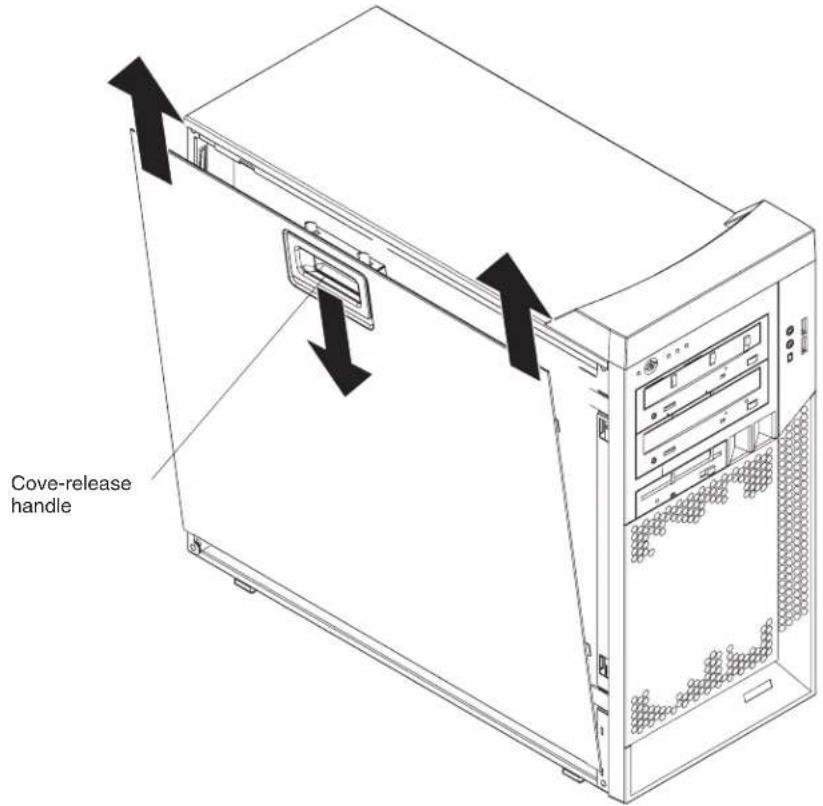
- Pull down on the cover-release handle; then, pull the cover straight up and lift the side cover off the computer and set it aside.
To replace the side cover, see "Replacing the side cover" on page 51.
Attention: For proper cooling and airflow, replace the side cover before turning on the computer. Operating the computer with the cover removed might damage computer components.
Removingthebezel
When working with some devices, such as additional optical drives, you must first remove the bezel to access the device. To install or remove options, you might find it easier to lay the computer on its side.
Complete the following steps to remove the bezel:
- Unlock the side-cover lock.
-
Remove the side cover (see "Removing the side cover" on page 25).
-
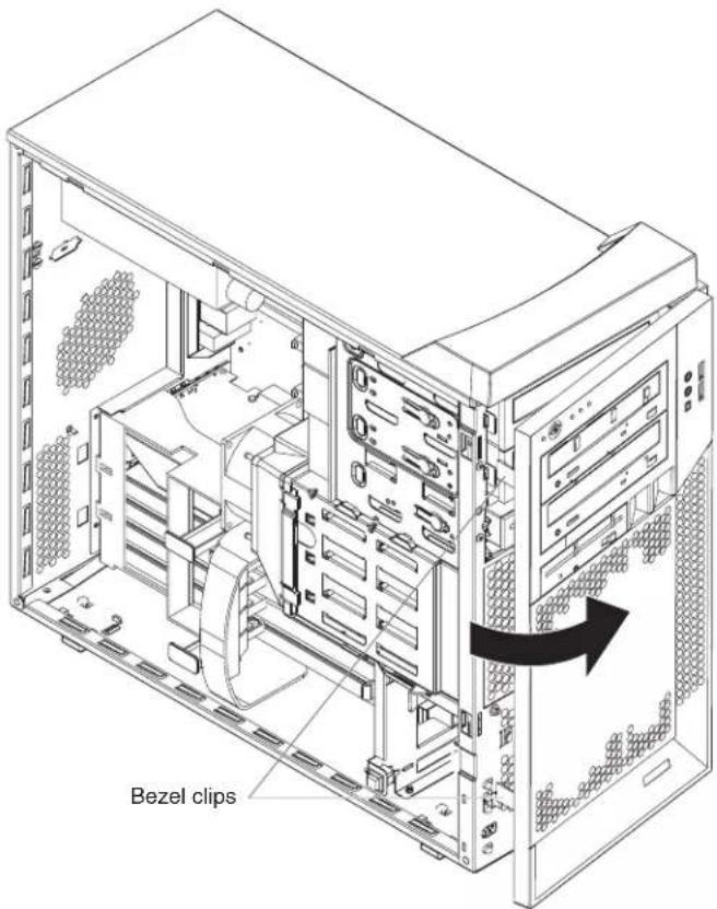
Locate the two bezel clips that are securing the bezel to the computer chassis. Gently lift and hold the bezel clips up and at the same time, rotate the bezel outward to disengage it from the side tabs; then, set the bezel aside.
For instructions for replacing the bezel, see "Replacing the bezel" on page 50.
Installinganadapter
The following notes describe the types of adapters that your computer supports and other information that you must consider when installing an adapter. See "System board option connectors" on page 71 for an illustration of the adapter slot locations.
- Read the documentation that comes with your operating system.
- Locate the documentation that comes with the adapter and follow those instructions in addition to the instructions in this chapter. If you need to change the switch or jumper settings on your adapter, follow the instructions that come with the adapter.
26 IntelliStation Z Pro Types 6223 and 6227: Hardware Maintenance Manual and Troubleshooting Guide
26 IntelliStation Z Pro Types 6223 and 6227: Hardware Maintenance Manual and Troubleshooting Guide
26 IntelliStation Z Pro Types 6223 and 6227: Hardware Maintenance Manual and Troubleshooting Guide
26 IntelliStation Z Pro Types 6223 and 6227: Hardware Maintenance Manual and Troubleshooting Guide
26 IntelliStation Z Pro Types 6223 and 6227: Hardware Maintenance Manual and Troubleshooting Guide
26 IntelliStation Z Pro Types 6223 and 6227: Hardware Maintenance Manual and Troubleshooting Guide
26 IntelliStation Z Pro Types 6223 and 6227: Hardware Maintenance Manual and Troubleshooting Guide
26 IntelliStation Z Pro Types 6223 and 6227: Hardware Maintenance Manual and Troubleshooting Guide
26 IntelliStation Z Pro Types 6223 and 6227: Hardware Maintenance Manual and Troubleshooting Guide
26 IntelliStation Z Pro Types 6223 and 6227: Hardware Maintenance Manual and Troubleshooting Guide
26 IntelliStation Z Pro Types 6223 and 6227: Hardware Maintenance Manual and Troubleshooting Guide
26 IntelliStation Z Pro Types 6223 and 6227: Hardware Maintenance Manual and Troubleshooting Guide
26 IntelliStation Z Pro Types 6223 and 6227: Hardware Maintenance Manual and Troubleshooting Guide
26 IntelliStation Z Pro Types 6223 and 6227: Hardware Maintenance Manual and Troubleshooting Guide
26 IntelliStation Z Pro Types 6223 and 6227: Hardware Maintenance Manual and Troubleshooting Guide
26 IntelliStation Z Pro Types 6223 and 6227: Hardware Maintenance Manual and Troubleshooting Guide
26 IntelliStation Z Pro Types 6223 and 6227: Hardware Maintenance Manual and Troubleshooting Guide
26 IntelliStation Z Pro Types 6223 and 6227: Hardware Maintenance Manual and Troubleshooting Guide
26 IntelliStation Z Pro Types 6223 and 6227: Hardware Maintenance Manual and Troubleshooting Guide
26 IntelliStation Z Pro Types 6223 and 6227: Hardware Maintenance Manual and Troubleshooting Guide
26 IntelliStation Z Pro Types 6223 and 6227: Hardware Maintenance Manual and Troubleshooting Guide
26 IntelliStation Z Pro Types 6223 and 6227: Hardware Maintenance Manual and Troubleshooting Guide
26 IntelliStation Z Pro Types 6223 and 6227: Hardware Maintenance Manual and Troubleshooting Guide
26 IntelliStation Z Pro Types 6223 and 6227: Hardware Maintenance Manual and Troubleshooting Guide
26 IntelliStation Z Pro Types 6223 and 6227: Hardware Maintenance Manual and Troubleshooting Guide
26 IntelliStation Z Pro Types 6223 and 6227: Hardware Maintenance Manual and Troubleshooting Guide
26 IntelliStation Z Pro Types 6223 and 6227: Hardware Maintenance Manual and Troubleshooting Guide
26 IntelliStation Z Pro Types 6223 and 6227: Hardware Maintenance Manual and Troubleshooting Guide
26 IntelliStation Z Pro Types 6223 and 6227: Hardware Maintenance Manual and Troubleshooting Guide
26 IntelliStation Z Pro Types 6223 and 6227: Hardware Maintenance Manual and Troubleshooting Guide
26 IntelliStation Z Pro Types 6223 and 6227: Hardware Maintenance Manual and Troubleshooting Guide
26 IntelliStation Z Pro Types 6223 and 6227: Hardware Maintenance Manual and Troubleshooting Guide
26 IntelliStation Z Pro Types 6223 and 6227: Hardware Maintenance Manual and Troubleshooting Guide
26 IntelliStation Z Pro Types 6223 and 6227: Hardware Maintenance Manual and Troubleshooting Guide
26 IntelliStation Z Pro Types 6223 and 6227: Hardware Maintenance Manual and Troubleshooting Guide
26 IntelliStation Z Pro Types 6223 and 6227: Hardware Maintenance Manual and Troubleshooting Guide
- Your computer comes with adapter connectors or slots. The video adapter is installed in the PCI Express x16 slot (slot 1). You can install up to five additional adapters in your computer in PCI slots 2 and 3, and PCI-X slots 4, 5, and 6.
- You can install full-length adapters in PCI slot 3, and PCI-X slots 4, 5, and 6. However, a full-length adapter will not fit in PCI slot 2 and is not supported. None of the expansion slots are hot-plug slots.
- Your computer supports 5.0 V signaling and universal PCI 32-bit/33 MHz adapters in PCI slots 2 and 3.
- Your computer supports 3.3 V signaling and universal PCI-X 64-bit/133 MHz adapters in PCI-X slot 4.
- Your computer supports 3.3 V signaling and universal PCI-X 64-bit/100 MHz adapters in PCI-X slot 5 and 6.
- Your computer uses a rotational interrupt technique to configure PCI adapters, which means that you can install a variety of PCI adapters that currently do not support sharing of PCI interrupts.
- If you install a ServeRAID 6i+ adapter, it must be installed in PCI-X slot 5.
- If you install an optional RAID adapter in your computer, you must reinstall the operating system and applications that came preinstalled on your computer.
•The system scans the PCI Express x16 slot (slot 1), PCI expansion slots 2 and 3, and PCI-X expansion slots 4 through 6 to assign system resources. Then, it starts the PCI devices in the following order, if you have not changed the default startup sequence: PCI Express x16 slot (slot 1), system-board integrated drive electronics (IDE), Serial ATA (SATA), or small computer system interface (SCSI) devices (including optional ServeRAID-6i+ controller), and then PCI-X slots 4 through 6. - For a list of supported options for your computer, go to http://www.ibm.com/pc/; then, select your country and navigate to the list of options for your computer.
Complete the following steps to install an adapter in your computer:
- Read the safety information beginning on page 127 and the guidelines in "Handling static-sensitive devices" on page 23
- Turn off the computer and all attached devices (see "Turning off the computer" on page 9); then, disconnect all external cables and power cords.
- Remove the side cover (see "Removing the side cover" on page 25).
- Determine the slot in which you want to install the adapter. Review the instructions that come with the adapter for any requirements, restrictions, or cabling instructions. It might be easier to route any cables before you install the adapter.
-
For full-length adapters, rotate the rear adapter-retention bracket to the open (unlocked) position (you might have to first remove any adapters that might be in the way). Press down on the bottom tab of the front adapter-retention bracket to release it (the tab is inside the fan compartment that is next to the front adapter-retention bracket). If you are installing a smaller adapter, rotate only the rear adapter-retention bracket.
-
Remove the expansion-slot cover. From the rear of the computer, press on the slot cover. Grasp it and pull it out of the expansion slot. Store it in a safe place for future use.
Attention: Expansion-slot covers must be installed on all empty slots. This maintains the electronic emissions standards of the computer and ensures proper ventilation of computer components.
- Follow the instructions that come with the adapter to set jumpers or switches, if any.
Attention: Avoid touching the components and gold-edge connectors on the adapter.
- If you are installing a full-length adapter, remove the blue adapter guide (if any) from the end of the adapter.

Attention: Be certain that the adapter is correctly seated in the expansion slot before you turn on the computer. Incomplete installation of an adapter might damage the system board or the adapter.
- Carefully grasp the adapter by the top edge or upper corners and move the adapter directly from the static-protective package to adapter slot (avoid touching the components and gold-edge connectors on the adapter). Align the adapter with the expansion slot guides; then, press the adapter firmly into the expansion slot.
Attention: Make sure that the adapter is correctly seated in the expansion slot before you turn on the computer. Incomplete installation of an adapter might damage the system board or the adapter.

-
Connect required cables to the adapter. Route cables so that they do not block the flow of air from the fans. If you are installing an optional SCSI adapter, see "Cabling an optional SCSI adapter" on page 30 for additional information.
-
If you have another adapter to install, repeat steps 4 through 10.
-
If you have installed a full-length adapter, press down on the top tab of the front adapter-retention bracket to lock it in place (the tab is inside the fan compartment that is next to the front adapter-retention bracket).
Note: If any adapter in your computer is large or has heavy cables attached to it, you can secure the adapter with a screw. Insert one backup expansion-slot screw (the screws are stored directly above the front adapter-retention bracket) through the top of each adapter bracket into the screw hole and secure the adapter before proceeding to the next step.
- If you have other options to install, do so now; otherwise, replace the side cover (see "Replacing the side cover" on page 51), reconnect the external cables and power cords, and turn on the computer.
CablinganoptionalSCSladapter
You can install an optional SCSI adapter in your computer to control the internal hard disk drives and provide additional RAID capabilities. With a SCSI adapter installed, you can configure the internal hard disk drives into disk arrays. You can also cable a SCSI adapter to external hard disk drives. See your SCSI adapter option documentation for complete instructions for installing a SCSI adapter in your computer and for additional information about SCSI adapters.
Notes:
- The SCSI cables that are used by the integrated SCSI controller cannot be used with an optional SCSI adapter.
- If you install a ServeRAID 6i+ adapter, it must be installed in slot 5; no cabling is required for this adapter.
Complete the following steps to cable an optional SCSI adapter:
- Install the SCSI adapter (see "Installing an adapter" on page 26).
- Connect the SCSI-signal cable to the adapter and one or more of the signal cable connectors to the rear of the SCSI devices.
- Connect the SCSI-activity-indicator cable to the adapter and to the SCSI-LED connector on the system board. See "System board internal connectors" on page 72 for the location of the SCSI-LED connector.

- Complete the installation of the optional SCSI adapter.
Installingadrive
Depending on your computer model, one or more of the following drives might be installed in your computer:
•Diskette drive (optional)
- Hard disk drive
- CD-ROM, CD-RW, or DVD/CD-RW combo drive
Your Z Pro Type 6223 computer comes with an IDE CD-ROM drive in bay 1 and a hard disk drive in bay 4.

The following notes describe the types of drives that your computer supports and other information that you must consider when installing drives:
•Make sure that you have all the cables and other equipment specified in the documentation that comes with the drive.
- Select the bay in which you want to install the drive.
- Check the instructions that come with the drive to see whether you need to set any switches or jumpers on the drive. If you are installing a SCSI device, be sure to set the SCSI ID for that device.
- You can install removable-media drives in bays 1, 2, and 3 only. Tape drives, diskette drives, CD-ROM, DVD/CD-RW, and DVD-ROM drives are examples of removable-media drives.
- You can install a 3.5-in. slim-high or 5.25-in. half-high removable-media drive, such as a tape backup drive, in bay 2.
- You can install a diskette drive or a 3.5-in slim-high hard disk drive in bay 3.
•To install a 3.5-in. drive in a 5.25-in. bay, you must use the 5.25-in. conversion kit.
- Your computer supports only one diskette drive: either a diskette drive in bay 3 or a USB drive connected to the USB connector on the front of the computer.
- Two Serial ATA hard disk drive connectors are on the system board.
- If you install SCSI hard disk drives and SATA hard disk drives in the same computer, note the following HostRAID considerations for hard disk drives:
- You can enable HostRAID on only one subsystem (SCSI or SATA).
- If HostRAID is enabled on a subsystem, you can install boot hard disk drives on that subsystem only.
If you fail to observe these restrictions, the computer will usually disable the BIOS for the last subsystem loaded, which typically is SCSI.
For more information about HostRAID, see in the User's Guide.
•The electromagnetic interference (EMI) integrity and cooling of the computer are protected by having all bays, PCI, and PCI-X slots covered or occupied. When you install a drive, PCI adapter, or PCI-X adapter, save the EMC shield and filler panel from the bay or the adapter slot cover in the event you later remove the drive or adapter.
- For a complete list of supported options for your computer, go to http://www.ibm.com/pc; then, select your country and navigate to the list of options for your computer.
Installingadriveinbay2or3
Complete the following steps to install a drive in bay 2 or 3:
-
Read the safety information beginning on page 127 and "Installation guidelines" on page 23.
-
Turn off the computer and peripheral devices, and disconnect the power cords and all external cables.
-
Remove the side cover (see "Removing the side cover" on page 25).
-
Remove the bezel (see "Removing the bezel" on page 26).
-
Use a screwdriver to pry the filler panel and EMC shield away from the computer.

Note: If you are installing a drive that contains a laser, observe the following safety precaution.
Statement3

CAUTION:
When laser products(suchasCD-ROMs, DVD drives, fiberoptic devices, or transmitters) are installed, not the following:
- Donotremovethecovers.Removingthecoversofthelaserproductcouldresultin exposuretohazardouslaserradiation.Therearenoserviceablepartsinsidethe device.
- Useofcontrolsoradjustmentsorperformanceofproceduresotherthanthose specifiedhereinmightresultinhazardousradiationexposure.

Danger
Some laser products contain an embedded Class 3A or Class 3B laser diode. Note the following. Laser radiation when open. Do not stare into the beam, do not view directly with optical instruments, and avoid direct exposure to the beam.
Class 1 Laser Product
Laser Klasse 1
Laser Klass 1
Luokan 1 Laserlaite
-
Touch the static-protective package containing the drive to any unpainted metal surface on the computer; then, remove the drive from the package and place it on a static-protective surface.
-
Set any jumpers or switches on the drive according to the documentation that comes with the drive.
Note: You might find it easier to install the new drive from the front and then attach the cables.
- To install a drive in bay 2, complete the following steps:
a. Remove the large drive clip attached to the side of bay 2 of the drive cage for bays 1, 2, and 3 (see the figure below). Slide the drive clip to the left to disengage it from the drive cage; then, snap the drive clip into the screw holes on the side of the drive.

b. If you are installing a 5.25-in. drive in bay 2, slide the drive into the drive bay until it snaps in place. If you are installing a 3.5-in. drive in bay 2, you must attach the 5.25-in. conversion kit, which you can order from IBM, to the 3.5-in. drive.
c. Continue with step 10.
- To install a drive in bay 3, use one of the following procedures:
Note: Only a 3.5-in. device can be installed in bay 3.
- If you are installing an external media device in bay 3, complete the following steps:
a. Remove the small drive clip that is attached to the side of bay 3 of the drive cage for bays 1, 2, and 3 (see the figure above). Slide the drive clip to the left to disengage it from the drive cage; then, snap the drive clip into the screw holes on the side of the drive.
b. Slide the drive into the drive bay until it snaps in place.
c. Continue with step 10.
- If you are installing a hard disk drive in bay 3, complete the following steps:
a. Push the drive into the bay from the rear of the drive cage; then, use the two screws to attach the drive to the drive cage.
b. Continue with step 10.
- Determine whether the drive is an IDE or SCSI device; then, connect one end of the applicable signal cable into the back of the drive and make sure that the other end of this cable is connected into the applicable IDE or SCSI connector on the system board.
- Route the signal cable so that it does not block the airflow to the rear of the drives or over the microprocessor and memory.
- If you have another drive to install or remove, do so now.
- Connect the power cable to the back of the drive. The connectors are keyed and can be inserted only one way.
- If you have other options to install or remove, do so now; otherwise, replace the bezel (see "Replacing the bezel" on page 50) and replace the side cover (see "Replacing the side cover" on page 51.
InstallingaSCSlorSATAdriveinbay4,5,or6
Some models come with non-hot-swap SCSI hard disk drives or Serial ATA (SATA) hard disk drives. Before you install a hard disk drive in bays 4, 5, and 6, read the following information:
- Read the documentation that comes with the drive for cabling instructions.
- Route the cable before you install the drive. Do not block the airflow from the fans.
- You can install up to four SCSI hard disk drives in your computer (SCSI models only).
- Your computer supports up to two Serial ATA hard disk drives.
Note: Your computer can support a third and fourth SATA drive if you install an optional ServeRAID-7t S-ATA controller. In addition, if you install the optional ServeRAID-7t S-ATA controller to add a third and fourth drive, all four SATA drives must then be connected to the ServeRAID-7t S-ATA controller instead of the system board. See the optional ServeRAID-7t S-ATA controller documentation for cabling instructions.
If you purchase a new SATA hard drive, you will also need to purchase a signal cable for it. IBM SATA hard drive option comes with a signal cable.
- Install hard disk drives in this sequence: bay 4, bay 5, bay 6, and then bay 3. See "Installing a drive in bay 2 or 3" on page 32 for information about how to install a hard disk drive in bay 3.
Complete the following steps to install a SCSI or Serial ATA (SATA) hard disk drive:
-
Read the safety information beginning on page 127 and the "Installation guidelines" on page 23.
-
Turn off the computer and peripheral devices and disconnect all external cables and power cords.
-
Unlock the side cover.
-
Remove the side cover (see "Removing the side cover" on page 25).
-
Disconnect the fan connector for the fan that is attached to the back of the drive cage from the system board.
-
Press in on the drive-cage release lever and rotate the drive cage all the way out of the computer until it locks into place over the drive-cage retention tab. The open ends of the drive slots and installed drives will face you.

- Grasp the fan latch on the fan assembly that is over the drive cage and pull it outward to disengage it from the drive cage and rotate it to the side.

-
If your computer has preinstalled hard disk drives in the drive cage, disconnect the power and signal cables from the rear of the drives.
-
Remove the empty drive tray from the drive bay in which you want to install the drive.
-
Touch the static-protective package containing the drive to any unpainted metal surface on the computer; then, remove the drive from the package and place it on a static-protective surface.
-
Set any jumpers or switches on the drive according to the documentation that comes with the drive.
-
Attach the new drive to the drive tray. Place the drive on the drive tray and align the holes on the drive with the mounting pins on the drive tray. Gently pull both sides of the drive tray outward and insert the mounting pins into the holes on the drive.

natural_image
Technical line drawing of a computer chassis with two ports and directional arrows indicating movement (no text or symbols)-
Align the drive assembly with the guide rails in the bay (make sure that the connector end of the drive is facing you).
-
Gently slide the drive assembly into the drive bay until the drive snaps into place.
-
Determine whether the new drive is a Serial ATA or SCSI device; then, connect one end of the applicable signal cable into the back of the drive and the other end of this cable into the applicable Serial ATA or SCSI connector on the system board. See "Power and signal cables for internal drives" on page 40 for additional information about cabling drives and "System board internal connectors" on page 72 for the location of the Serial ATA and SCSI connectors on the system board. If there are open connectors on the cables connecting existing Serial ATA or SCSI drives, you can use these cables to connect the new drive.
-
Route the signal cable so that it does not block the airflow to the rear of the drives or over any microprocessor.
-
Connect the power cables to the back of the drives. The connectors are keyed and can be inserted only one way.
-
Push the drive cage outward, and press in on the drive-cage release tab; then, rotate the drive cage back into the computer.
-
Reconnect the connector for the fan that is attached to the back of the drive cage to the system board.
-
If you have other options to install or remove, do so now. Otherwise, replace the side cover (see "Replacing the side cover" on page 51.
-
Reconnect the external cables and power cords; then, turn on the attached devices and the computer.
Powerandsignalcablesforinternaldrives
Your computer uses cables to connect IDE, Serial ATA, and SCSI devices to the power supply and to the system board. (See "System board internal connectors" on page 72 for the location of system-board connectors.) Review the following information before connecting power and signal cables to internal drives:
•The drives that are preinstalled in your computer come with power and signal cables attached. If you replace any drives, remember which cable is attached to which drive, or label the cables.
- When you install a drive, make sure that one of the signal-cable connectors is connected to the drive and that the connector at the other end of the signal cable is connected to the system board.
•The computer has one IDE bus, which is primary.
- If you have only one IDE device on a cable, it must be set as a master device.
The following cables are provided:
- Power cables: Four-wire power cables connect the drives to the power supply. At the end of these cables are plastic connectors that attach to different drives; these connectors vary in size. With Serial ATA drives, you can use either a four-wire power cable or a five-wire Serial ATA power cable, but do not use both at the same time (use one or the other).
- Signal cables: Signal cables typically are flat cables, also called ribbon cables, that connect IDE, Serial ATA, SCSI, and diskette drives to the system board. Two or three types of signal cables come with your computer:
- IDE: The wider IDE signal cable has three connectors. One of these connectors is attached to the drive, one is a spare, and the third is attached to the primary or secondary IDE connector on the system board. The spare connector can be used to connect additional IDE drives to your computer.
Note: The optical drive is attached to an ATA 100 signal cable. ATA 100 signal cables are color-coded. The blue connector is connected to the system board. The black connector is connected to the master IDE device. The gray middle connector is connected to the subordinate IDE device.
- Serial ATA: The narrower, black signal cable has two connectors. One is connected to the SATA drive, and the other is connected to the connector on the system board. Each SATA drive comes with a cable. If you install an additional SATA drive, you will need an additional cable.
- SCSI: The following cables can be used to attach SCSI devices to the integrated SCSI controller on the system board:
- An Ultra320 twisted ribbon cable connects the internal Ultra320 SCSI hard disk drive to the SCSI connector on the system board. This cable has four additional connectors for attaching more internal SCSI devices.
- A round SCSI cable connects external SCSI devices to the integrated SCSI controller on the system board. For more information about connecting SCSI devices, see the SCSI documentation.
Installingmemorymodules
The following notes describe the types of dual inline memory modules (DIMMs) that the computer supports and other information that you must consider when installing DIMMs:
•The computer comes with either two 256 MB or two 512 MB memory DIMMs installed in DIMM 1 and DIMM 2 memory connectors. The second pair of DIMMs must be installed in DIMM 3 and DIMM 4 memory connectors and the third pair in DIMM 5 and DIMM 6 memory connectors.
- DIMMs must be installed in matched pairs. The DIMMs in each pair must be the same size, speed, type, and technology as each other but do not have to match the other pairs. You can mix compatible DIMMs from various manufacturers.
• Install only 1.8 V, 240-pin, double-data-rate 2 (DDR2), PC2-3200, registered, synchronous dynamic random-access memory (SDRAM) with error correcting code (ECC), dual inline memory modules (DIMMs). These DIMMs must be compatible with the latest PC2-3200 SDRAM buffered DIMM specification. For a list of supported options for your computer, go to http://www.ibm.com/pc/; then, select your country and navigate to the list of options for your computer.
- The DIMM-installation sequence is based on single-rank, double-rank, and mixing single-rank and double-rank memory DIMMs. Single-rankDIMMs are 256 MB, 512 MB, and 1 GB memory modules. Double-rankDIMMs are 2 GB memory modules. The following table lists the DIMM-installation sequence for the computer maximum memory capacity using mixed single-rank and double-rank DIMMs.
Notes:
- Do not install four, 2 GB double-rank DIMMs for the computer maximum capacity (8 GB) configuration, the computer does not support it.
- You can install pairs of 256 MB, 512 MB, 1 GB, and 2 GB DIMMs in the computer, but for the computer maximum capacity, you must use the DIMM-sequence in the table below.
- You can install any combination of DIMM pairs in the computer, however, you can install only two, 2 GB double-rank DIMMs in the computer and they must go in DIMM connectors 1 and 2. Do not install 2 GB double-rank DIMMs in any connectors other than DIMM connectors 1 and 2.
- If you order memory DIMMs from IBM, the variable 2Rin the description indicates that the DIMM is a double-rank 2 GB DIMM.
Table2.Maximummemorycapacity(8GB)andinstallationsequencemixingsingle-rank anddouble-rankDIMMs
| DIMMpairDIMMconnectorsDIMMsizeRank | ||
| First pair 1, 2 2 GB Double-rank | ||
| Second pair 3, 4 1 GB Single-rank | ||
| Third pair 5, 6 1 GB Single-rank |
•The system board contains six DIMM connectors and supports two-way memory interleaving when the DIMMs are installed in pairs and functioning properly. If one DIMM in the pair fails, the computer runs in single-channel mode (non-interleaving). A failed DIMM must be replaced as soon as possible; otherwise, the computer will not start (boot).
•The DIMM options that are available for the computer are 256 MB, 512 MB, 1 GB, and 2 GB memory modules. The computer supports a minimum of 512 MB and a maximum of 8 MB (when using 2 GB double-rank DIMMs) of system memory.
Important: Although the computer supports a maximum of 8 GB of system memory, the Microsoft Windows operating systems recognize and support a maximum of 4 GB of system memory.
•The memory controller in the computer provides Chipkill memory protection if the DIMMs are 1 GB or larger, or if the computer is populated with 512 MB x4 DIMMs. Chipkill memory protection is a technology that protects the computer from a single chip failure on a DIMM.
•The amount of usable memory is reduced depending on the system configuration. A certain amount of memory must be reserved for system resources. The BIOS displays the total amount of installed memory and the amount of configured memory.
Complete the following steps to install DIMMs:
- Read the safety information beginning on page 127 and "Handling static-sensitive devices" on page 23
- Turn off the computer and all attached devices (see "Turning off the computer" on page 9); then, disconnect all power cords and external cables.
- Remove the side cover (see "Removing the side cover" on page 25).
- Locate the DIMM connectors on the system board. Determine the connectors into which you will install the DIMMs. See Table 2 on page 41 for additional information on DIMM-installation sequences.
Table3.DIMMinstallationsequence
| DIMMpairDIMMconnectors | |
| First pair 1, 2 | |
| Second pair 3, 4 | |
| Third pair 5, 6 |
- Gently open the retaining clip, if necessary, remove any existing DIMM.
- Touch the static-protective package containing the DIMM to any unpainted metal surface on the computer. Then, remove the new DIMM from the package.
-
Gently open the retaining clip on each end of the DIMM slot. Turn the DIMM so that the pins align correctly with the connector.
-
Insert the DIMM into the connector. Firmly press the DIMM straight down into the connector by applying pressure on both ends of the DIMM simultaneously. The retaining clips snap into the locked position when the DIMM is firmly seated in the connector. If there is a gap between the DIMM and the retaining clips, the DIMM has not been correctly installed. Open the retaining clips, remove the DIMM, and then reinsert it.

-
If you have other options to install or remove, do so now. Otherwise, replace the side cover (see "Replacing the side cover" on page 51.
-
Reconnect the external cables and power cords. Turn on the attached devices, and turn on the computer.
Installingasecondmicroprocessor
Your computer comes with one microprocessor installed on the system board. Your computer supports up to two microprocessors. With two microprocessors, your computer can operate as a symmetric multiprocessing (SMP) computer. With SMP, certain operating systems and application programs can distribute the processing load among the microprocessors.
Note: When installing microprocessor options, lay the computer on its side.
The following notes describe information that you must consider when installing an additional microprocessor in your computer:
- Read the documentation that comes with the microprocessor to determine whether you need to update the computer basic input/output system (BIOS) code. The most current level of BIOS code for the computer is available from http://www.ibm.com/support.
•(Optional) Obtain an SMP-capable operating system. For a list of supported operating systems, go to http://www.ibm.com/pc/us/compat/.
• To ensure proper computer operation, use microprocessors that have the same cache size and type, and the same clock speed. Microprocessor internal and external clock frequencies must be identical. You can use the Configuration/Setup Utility program in your computer to determine the specific type of microprocessor on your system board.
Important: The first microprocessor must always be installed in the Microprocessor 1 socket.
- The microprocessor speeds are automatically set for this computer; therefore, you do not need to set any microprocessor frequency-selection jumpers or switches.
- Terminator cards are not required for empty microprocessor sockets. However, for airflow, an empty microprocessor socket must contain a microprocessor baffle.
- If you need to replace a microprocessor, see "Microprocessor and heat sink" on page 60.
- For additional illustrations of the system-board components, see "System board option connectors" on page 71.
• To order additional microprocessor options, contact your IBM marketing representative or authorized reseller. - For a list of supported microprocessor options for your computer, go to http://www.ibm.com/pc; then, select your country and navigate to the list of options for your computer
The Microsoft Windows XP operating system that comes preinstalled on your computer automatically configures itself when an additional microprocessor is installed. Other operating systems might have to be manually configured to support an additional microprocessor. See the User's Guide on the IBM IntelliStation DocumentationCD for instructions.
Complete the following steps to install an additional microprocessor:
- Read the safety information beginning on page 127 and the guidelines in "Handling static-sensitive devices" on page 23.
-
Turn off the computer and all attached devices. (See "Turning off the computer" on page 9.)
-
Disconnect all external cables and power cords.
-
Remove the side cover (see "Removing the side cover" on page 25).
-
Disconnect the fan connector for the fan that is attached to the back of the drive cage from the system board.
-
Press in on the drive-cage release lever and rotate the drive cage all the way out of the computer until it locks into place over the drive-cage retention tab. The open ends of the drive slots and installed drives will face you.

-
Move or disconnect any cables that might be in the way so you can remove the microprocessors' air baffle.
-
Remove the air baffle for the microprocessors by pulling it outward and lifting it out of the computer.
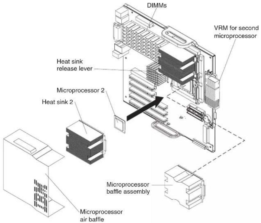
-
Locate the second microprocessor socket (Microprocessor 2) on the system board.
-
Remove the microprocessor baffle assembly from the second microprocessor socket.
a. Press down on the blue touch point of the heat-sink release lever and rotate the lever all the way out until it stops.
b. Grasp the front of the microprocessor baffle assembly and tilt it up while pulling the rear flange out of the heat-sink retention module; then, lift it out of the computer and store it in a safe place.
-
If the second microprocessor socket is covered with protective film or a label, peel and remove the film or label.
-
Install the microprocessor:
a. Touch the static-protective package containing the new microprocessor to any unpainted metal surface on the computer; then, remove the microprocessor from the package.
b. Rotate the locking lever on the microprocessor socket from its closed and locked position until it stops or clicks in the fully open position (approximately 135°).
Attention: You must ensure that the locking lever on the microprocessor socket is in the fully open position before you insert the microprocessor in the socket. Failure to do so might result in permanent damage to the microprocessor, microprocessor socket, and system board.
c. Position the microprocessor over the microprocessor socket. Align the triangle on the corner of the microprocessor with the triangle on the corner of the socket and carefully press the microprocessor into the socket.
Attention:
1) Do not use excessive force when pressing the microprocessor into the socket.
2) Make sure that the microprocessor is oriented and aligned correctly with pin number 1 in the socket before you try to close the lever. The following illustration shows the alignment marks for both microprocessors and sockets.

d. Carefully close the lever to secure the microprocessor in the socket.
- Install the heat sink on the microprocessor.

a. Remove the plastic cover from the bottom of the heat sink.
Attention: Do not set the heat sink down after you remove the plastic cover and do not touch the thermal grease on the bottom of the heat sink. Touching the thermal grease will contaminate it. If the thermal grease on the heat sink becomes contaminated, replace the heat sink.
b. Align the heat sink (grease side down) over the microprocessor and retention bracket.
c. Slide the rear flange of the heat sink rearward into the opening beneath the retention-bracket spring.
d. Press down firmly on the front of the heat sink until it is seated correctly.
e. Secure the heat sink to the microprocessor by rotating the heat-sink release lever to the closed position and hooking it underneath the tab on the microprocessor socket.
f. Insert the voltage regulator module (VRM) into the VRM connector.
- Replace the air baffle for the microprocessors. Slant the front of the air baffle for the microprocessors downward at an angle while moving it forward; then, rotate the rear of the air baffle down until it snaps into place (it will become stationary).
- Rotate the drive cage back into the computer and reconnect the fan connector on the fan assembly on the drive cage to the system board.
- If you have other options to install or remove, do so now. Otherwise, replace the side cover (see "Replacing the side cover" on page 51.
- Reconnect the external cables and power cords. Turn on the attached devices, and turn on the computer.
InstallinganexternalSCSlcable
To install an external SCSI connector on the rear of the computer, install an external SCSI interface option. For a list of supported external SCSI interface options for your computer, go to http://www.ibm.com/pc/.
The external SCSI interface option contains a SCSI cable with a connector at one end and on the other end another connector or an expansion-slot cover with an embedded connector. Complete the following steps to install and route the SCSI cable in the computer:
- Turn off the computer and all peripheral devices. Disconnect all power cords; then, disconnect all external signal cables from the computer.
- Remove the side cover (see "Removing the side cover" on page 25).
- Open the front adapter-retention bracket and remove the rear adapter-retention bracket from the PCI-X slots (see "Installing an adapter" on page 26 for instructions). You might also have to remove longer adapters for access to the SCSI connectors on the system board.
- Connect the SCSI signal cable to the connector for SCSI channel A on the system board. See "System board internal connectors" on page 72 for the location of the SCSI channel A connector.
- Route the SCSI cable between the chassis and PCI-X slot 5 to the back of the computer. Make sure that the cable does not block the flow of air to the microprocessors or hard disk drives.
- Attach the external connector to the rear of the computer.
- If the external end of the SCSI cable has a standard SCSI connector, complete the following steps:
a. Remove the SCSI-connector knockout from the rear of the computer.
b. Insert the external SCSI connector on the SCSI cable into the knockout opening and secure it with the attached screws.
- If the external end of the SCSI cable has an expansion-slot cover with an embedded connector, complete the following steps:
a. Remove an expansion-slot cover from an available PCI-X slot.
b. Insert the expansion-slot cover with embedded connector into the slot opening.
-
Replace any adapters that you removed in step 3. Close the front adapter-retention bracket and replace the rear adapter-retention bracket.
-
Replace the cover (see "Replacing the side cover" on page 51).
-
Reconnect the external cables and power cords. Turn on the attached devices, and turn on the computer.
-
Use the SCSISelect program to configure SCSI channel A.
Installingasecurityropeclip
To help prevent hardware theft, you can add a security rope clip and cable to your computer. After you add the security cable, make sure that it does not interfere with other cables that are connected to the computer.
Before you begin, obtain the following items:
•A flat-blade screwdriver
•An adjustable wrench
- A 19-mm (0.75-in.) rope clip or wire rope (similar to National Manufacturing number 3230, stock number 176-735)
- Threaded nuts that fit the rope clip
•A security cable
•A lock, such as a combination lock or padlock
Complete the following steps to install a rope clip:
-
Turn off the computer and all attached devices.
-
Disconnect all external cables and power cords; then, remove the side cover. See "Removing the side cover" on page 25
-
Use a screwdriver to remove the two metal knockouts.
-
Insert the rope clip through the rear panel; then, attach and tighten the nuts.
-
Thread the cable through the rope clip and around an object that is not part of or permanently secured to the building structure or foundation and from which the cable cannot be removed. Fasten the cable ends together with a lock. After you add the security cable, make sure that it does not interfere with other cables that are connected to the computer.

-
If you have other options to install or remove, do so now; otherwise, replace the side cover (see "Replacing the side cover" on page 51)
-
Reconnect the external cables and power cords. Turn on the attached devices, and turn on the computer.
Replacingthebezel
Complete the following steps to replace the bezel:
-
Insert the tabs on the side of the bezel into the matching holes on the computer chassis.
-
Push the bezel toward the computer until the tabs and bezel clips snap into place.
Replacingthesidecover
Complete the following steps to replace the side cover.
-
Before installing the cover, check that all cables, adapters, and other components are installed and seated correctly and that you have cleared all work tools from inside the computer.
-
Install the side cover by placing it into position on the computer. Make sure that the lip on the bottom of the cover rests inside the ledge on the bottom of the chassis before rotating the cover toward the computer. Press down and forward on the cover until it locks.

natural_image
Line drawing of a server rack unit with black arrows indicating directional movement (no text or symbols)-
Reconnect the external cables and power cords to the computer.
-
Turn on the attached devices; then, turn on the computer.
Connectingexternaloptions
You can connect a number of optional external devices to the connectors on the rear and front of the computer.
Complete the following steps to connect an external device:
- Read the safety information beginning on page 127, the guidelines in "Handling static-sensitive devices" on page 23, and the documentation that comes with your options.
- Turn off the computer and all attached devices (see "Turning off the computer" on page 9).
- Follow the instructions that come with the option to prepare it for installation and to connect it to the computer.
If you are attaching a SCSI device, see "Ultra320 SCSI connector" on page 56 for SCSI ID and cabling information.
Input/outputconnectors
Connect optional external devices to the connectors on the front and rear of the computer.
Your computer has the following input/output (I/O) connectors:
•One audio line in
- Two audio line out
• Two audio microphone
•One Ethernet
•Two IEEE 1394A (FireWire)
•One keyboard
•One mouse
•One parallel
- Two serial
•Six Universal Serial Bus (USB) 2.0
•One video
The following illustration shows the locations of the connectors on the rear of the computer. See "Controls, LEDs, and connectors" on page 6 for the locations of the connectors on the front of the computer.

The following sections describe these connectors.
Audioconnectors
Use the audio connectors to connect external audio equipment to the computer. The following illustration shows the audio connectors.
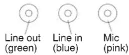
Linein
There is one line-in connector on the rear of the computer. The computer receives audio signals through this connector from an external audio device.
Lineout
There are two line-out connectors, one on the front and one on the rear of the computer. The computer sends audio signals through this connector to powered speakers with built-in amplifiers, headphones, a multimedia keyboard, or the audio line-in connector on a stereo system. The internal speaker in the computer is disabled when a device is attached to this connector.
Mic
There are two microphone connectors, one on the front and one on the rear of the computer. Connect a microphone to this connector to record sounds onto the hard disk or to use speech-recognition software.
Auxiliary-device(pointing-device)connector
There is one auxiliary-device connector on the rear of the computer. Use this connector to connect a mouse or other pointing device. The following illustration shows an auxiliary-device connector.

Ethernet(RJ-45)connector
There is one Ethernet connector on the rear of the computer. Use this connector to connect the computer to a 10-Mbps, 100-Mbps, or 1000-Mbps network. The following illustration shows an Ethernet connector.

Connect a Category 3, 4, or 5 unshielded twisted-pair (UTP) cable to this connector. The 100BASE-TX and 1000BASE-T Fast Ethernet standards require Category 5 or higher cabling.
The Ethernet connector has one LED that indicates Ethernet-link status. When this LED is lit, it indicates that there is an active connection on the Ethernet port. Activity between the computer and the network is indicated by the Ethernet transmit/receive activity LEDs on the front and rear of the computer (see “Controls, LEDs, and connectors” on page 6).
IEEE1394A(FireWire)connector
There is one 4-pin IEEE 1394A (FireWire) connector on the front of the computer and one 6-pin IEEE 1394A (FireWire) connector on the rear of the computer. Use these connectors to connect IEEE 1394 (FireWire) devices. The following illustrations show the IEEE 1394A (FireWire) connectors.
4-pinIEEE1394A(FireWire)connector(front)
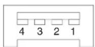
6-pinIEEE1394A(FireWire)connector(rear)
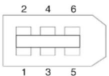
Keyboardconnector
There is one keyboard connector on the rear of the computer. Use this connector to connect a PS/2 (non-USB) keyboard. The following illustration shows a keyboard connector.

If you attach a keyboard to this connector, USB ports and devices are disabled during the power-on self-test (POST).
Parallelconnector
There is one parallel connector on the rear of the computer. Use this connector to connect a parallel device. The following illustration shows a parallel connector.

The parallel connector supports three standard Institute of Electrical and Electronics Engineers (IEEE) 1284 modes of operation: standard parallel port (SPP), enhanced parallel port (EPP), and extended capability port (ECP). If you configure the parallel port to operate in bidirectional mode, it supports the ECP and EPP modes. When the parallel connector is configured as bidirectional, use an IEEE 1284-compliant
cable that does not exceed 3 meters (9.8 ft). Use the Devicesandl/OPorts options in the IBM Configuration/Setup Utility program to configure the parallel connector as bidirectional.
Serialconnectors
There are two serial connectors on the rear of the computer. Use these connectors to connect serial devices. The following illustration shows a serial connector.
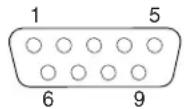
Ultra320SCSIconnector
Your computer has an integrated SCSI controller. This dual-channel controller supports two independent, Ultra320 SCSI channels that support up to 15 SCSI devices each. The SCSI connectors for the channels are on the system board. The controller has the following features:
- Double-transition clocking to achieve up to 320 MBps (megabytes per second) data-transfer rates
- Domain name validation to negotiate compatible data-transfer speeds with each device
•Cyclic-redundancy checking (CRC) to improve data reliability
•An active terminator for SCSI bus termination
The following illustration shows a SCSI connector.

SCSlcablingrequirements
You can install four internal SCSI devices using the SCSI signal cable that comes with some computer models. If you plan to attach external SCSI devices, you can order an additional SCSI cable, remove the SCSI knockout from the rear of the computer, and connect the new cable from the SCSI channel A connector on the system board to this opening. To select and order the correct cables for use with external devices, contact your IBM marketing representative or authorized reseller.
See "System board internal connectors" on page 72 for the locations of the SCSI connectors.
If you want to attach external SCSI devices to the computer without using the internal SCSI channel B, you must install an optional SCSI adapter.
SettingSCSIIDs
Each SCSI device that is connected to a SCSI controller must have a unique SCSI ID. This ID enables the SCSI controller to identify the device and ensure that different devices on the same SCSI channel do not attempt to transfer data simultaneously. SCSI devices that are connected to different SCSI channels can have duplicate SCSI IDs. See the information that comes with the device for instructions for setting its SCSI ID.
UniversalSerialBusconnectors
There are six Universal Serial Bus (USB) 2.0 connectors, two on the front and four on the rear of the computer. Use the USB connectors to connect optional telephony and multimedia devices. USB 2.0 technology transfers data at up to 480 Mbps (Mb per second) with a maximum of 127 external devices and a maximum signal distance of 5 meters (16 ft) per segment (if the device that is attached to the computer is a USB 2.0 device). If multiple USB devices are attached to the computer, the USB hub must be USB 2.0; otherwise, all USB 2.0 devices will transfer data at 12 Mbps. Using Plug and Play technology, USB devices are configured automatically. The following illustration shows a USB connector.

Use a 4-pin USB cable to connect an external devices to a USB connector.
If you connect a PS/2 (non-USB) keyboard to the keyboard connector, USB ports and devices are disabled during power-on self-test (POST).
If you connect a USB keyboard that has a mouse port, the keyboard emulates a mouse, and you cannot disable the mouse settings in the Configuration/Setup Utility program.
Videoconnector
The PCI Express x16 adapter, which is in PCI slot 1 on the system board, provides the video connector. This connector is on the rear of the computer. Use the video connector to connect a monitor or other display device. The following illustrations show examples of different video connectors.
Analogvideoconnector

Digital(DVI-I)videoconnector

Dualmonitorsystem-59(DMS-59)videoconnector

Some models come with a digital video interface (DVI) connector for connecting a digital monitor. If you have problems viewing information with a second monitor, refer to the User's Guide.
Models with the NVIDIA Quadro FX 1300 or NVIDIA Quadro FX 3400 video adapter come with a DVI-I to VGA style analog converter for each DVI-I connector.
Attention: To get the best performance from the NVIDIA Quadro FX 3400 video adapter, you must connect the video adapter to the computer power supply. Otherwise, the video adapter will be operating with very limited power, resulting in a decrease in performance for some applications. Use the PCI Express x16 external power drop to connect the video adapter to the computer power supply. The following illustration shows the location of the video adapter power connector.

Models with the NVIDIA Quadro NVS 280 video adapter come with a dual monitor system-59 (DMS-59) to dual-analog monitor pigtail cable. If you want to set up two digital monitors, you will have to purchase a separate dual-digital monitor cable.
Chapter5.Fieldreplaceableunits
Microprocessor and heat sink 60
CD-ROM drive. 6 1
Non-hot swap power supply. 6 2
Rear-adapter retention bracket 6 3
I/O card retainer. 6 4
Front (microprocessor) fan . . . . . . . . . . . . . . . . . . . . . . 6 5
Hard drive fan . . . . . . . . . . . . . . . . . . . . . . . . . . . . . . 6 6
Power/LED switch assembly 6 8
Card/bracket assembly 6 9
Speaker. 7 0
System board 7 1
System board option connectors . . . . . . . . . . . . . . . . . . . 7 1
System board internal connectors. 7 2
System board external connectors. 7 3
System board error LEDs. 7 4
System board jumpers and switches. 7 5
Removing the system board. 7 6
Top/side cover. 7 8
Bezel-release latch. 7 9
Handle assembly. 8 1
The following information describes procedures for removing and installing certain components inside the system. Only a qualified service technician is authorized to replace the components described in this section.
Important: The field replaceable unit (FRU) procedures are intended for trained servicers who are familiar with IBM IntelliStation Z Pro products. See the parts listing in "System replaceable units" on page 117 to determine if the component being replaced is a customer replaceable unit (CRU) or a FRU.
Note: Before servicing this system, read "Installation guidelines" on page 23 and Appendix B, "Safety information," on page 127.
Microprocessorandheatsink
Beforeyoubegin:
- Read the "Installation guidelines" on page 23.
- Read Appendix B, "Safety Information," on page 127
- Review the information in "System reliability considerations" on page 23.
To remove the microprocessor and heat sink, complete the following steps.

- Turn off the computer and remove external cables.
- Remove the side cover (see "Removing the side cover" on page 25).
- Disconnect any cables that impede access to the microprocessor.
- Remove the heat sink from the microprocessor:
a. Press the microprocessor-baffle release lever down, move it toward the other microprocessor, and lift it up to the open position.
b. Slide the heat-sink assembly toward the front of the computer and tip the rear flange out of the heat-sink socket.
c. Lift the heat sink up and out of the computer.
Note: It might be necessary to gently twist the heat sink to loosen it from the microprocessor.
Important: Be careful when handling the microprocessor and heat sink. If the thermal grease between the microprocessor and heat sink will be reused, do not contaminate it. If replacement thermal grease is provided with the replacement part, be sure to remove all traces of existing thermal grease from the remaining part before applying the new thermal grease.

-
Rotate the microprocessor socket lever arm upward to its maximum vertical position (135°), and lift the microprocessor up and out of the computer.
-
To install a microprocessor, see "Installing a second microprocessor" on page 44, beginning with step 8 on page 45.
CD-ROMdrive
Beforeyoubegin:
- Read Appendix B, "Safety information," on page 127.
- Review the information in "System reliability considerations" on page 23.
To remove the CD-ROM drive, complete the following steps:
- Turn off the computer, if it is on.
- Disconnect the power cord from the power source and from the computer; then, disconnect all external cables.
- Remove the side cover (see "Removing the side cover" on page 25).
- Remove the front bezel (see "Removing the bezel" on page 26).
- Disconnect the CD-ROM drive connector and power cables from the rear of the drive.
- Press the touch point on the raised area of the drive cage for the CD-ROM drive and gently slide the drive out of the front of the computer.
For instructions for replacing the CD-ROM drive, see "Installing a drive in bay 2 or 3" on page 32.
Non-hotswappowersupply
Beforeyoubegin:
- Read Appendix B, "Safety information," on page 127
- Review the information in "System reliability considerations" on page 23.
To remove the non-hot-swap power supply, complete the following steps:
- Turn off the computer, if it is on.
- Disconnect the power cord from the power source and from the computer; then, disconnect all external cables.
- Remove the cover (see "Removing the side cover" on page 25).
- Disconnect internal cables from the power supply to the system board and any other components to which it is attached, making a note of where they connect.
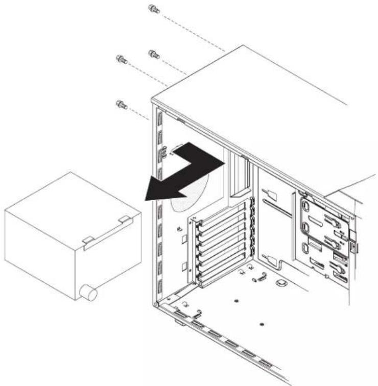
natural_image
Technical line drawing of a server rack with internal components and an open case (no text or symbols)- Remove the screws from the rear of the computer.
- Gently move the power supply away from the chassis and lift it out of the computer.
To replace the non-hot-swap power supply, complete the following steps:
-
Align the tabs on the top of the power supply with the tab slots on the underside of the top rear of the chassis, and slide the power supply toward the rear of the chassis.
-
Secure the power supply to the rear of the chassis with the four screws.
-
Reconnect the power cables.
Rear-adapterretentionbracket
Beforeyoubegin:
- Read Appendix B, "Safety information," on page 127.
- Review the information in "System reliability considerations" on page 23.
To remove the rear-adapter retainer, complete the following steps:
- Turn off the computer, if it is on.
- Disconnect the power cord from the power source and from the computer; then, disconnect all external cables.
- Remove the side cover (see "Removing the side cover" on page 25).
- Remove all adapters (see "Installing an adapter" on page 26).
- Grasp the rear adapter retainer, and gently slide the top and bottom tabs out of the notches.

To replace the rear adapter retainer, reverse the steps.
I/Ocardretainer
Beforeyoubegin:
- Read Appendix B, "Safety information," on page 127
- Review the information in "System reliability considerations" on page 23.
To remove the I/O card retainer, complete the following steps:
- Turn off the computer, if it is on.
- Disconnect the power cord from the power source and from the computer; then, disconnect all external cables.
- Remove the side cover (see "Removing the side cover" on page 25).
- Remove all adapters (see "Installing an adapter" on page 26).

- Squeeze the two release tabs on the card retainer.
- Pull out on the two pivot points of the retainer and remove it from the computer.
To replace the I/O card retainer, reverse the steps.
Front(microprocessor)fan
Beforeyoubegin:
- Read Appendix B, "Safety information," on page 127.
- Review the information in "System reliability considerations" on page 23.
To remove a front fan, complete the following steps:
- Turn off the computer, if it is on.
- Disconnect the power cord from the power source and from the computer; then, disconnect all external cables.
- Remove the cover (see "Removing the side cover" on page 25).
- Remove the front bezel (see "Removing the bezel" on page 26).
- Pivot the drive cage out until it locks in position.

- Squeeze the fan baffle release tabs so that they release from the notches in the chassis.
Note: It might be easier to perform this procedure if you remove adapters and remove the front I/O card retainer.
-
From inside the computer, grasp the fan baffle, slide it out, and remove it from the computer.
-
Note where the fan cable connects to the system board, and disconnect the cable from the system board.
Note: See the system service label or "System board internal connectors" on page 72 for system board connector locations.
-
Use side cutters to cut the four rubber extensions that secure the fan to the chassis.
-
Remove the fan from the computer, making sure that no rubber extensions are left loose in the computer.
To install the new front fan assembly, complete the following steps:
- Place the fan in position against the chassis.
- Guide the rubber extensions through the apertures.
- Use needle-nosed pliers to pull the extensions through the apertures.
- Connect the fan cable.
- Slide the fan baffle into place and guide the tabs into the slots in the chassis until they lock in place.
- If you removed the adapters and front I/O card retainer, replace the retainer and then the adapters.
- Press the touch point on the side of the drive cage and lower it back into place in the computer.
- Replace the bezel.
- Replace the side cover.
Harddrivefan
Beforeyoubegin:
- Read Appendix B, "Safety information," on page 127.
- Review the information in "System reliability considerations" on page 23.
To remove a rear fan, complete the following steps:
- Turn off the computer, if it is on.
- Disconnect the power cord from the power source and from the computer; then, disconnect all external cables.
- Remove the side cover (see "Removing the side cover" on page 25).
- Rotate the drive cage up until it locks in position.
- Note where the fan cable connects to the system board, and disconnect the cable from the system board.
Note: See the system service label or "System board internal connectors" on page 72 for system board connector locations.

- On the side of the drive cage facing the front of the computer, grasp the fan latch and pull it away from the drive cage, rotating it up.
- Grasp the duct at the pivot points and pull them outward until they detach from the drive cage.
- Set the assembly on a level work surface with the fan facing up.
- Use side cutters to sever the four rubber extensions securing the fan to the duct and remove the fan.
To install the new rear fan assembly, reverse the previous steps, guiding the rubber extensions through the apertures and using needle-nosed pliers to pull them through.
Power/LEDswitchassembly
Beforeyoubegin:
- Read the "Installation guidelines" on page 23.
- Read Appendix B, "Safety Information," on page 127
- Review the information in "System reliability considerations" on page 23.
To remove the power/LED switch assembly, complete the following steps:
- Turn off the computer, if it is on.
- Disconnect the power cord from the power source and from the computer; then, disconnect all external cables.
- Remove the side cover (see "Removing the side cover" on page 25).
- Remove the front bezel (see "Removing the bezel" on page 26).
- Note where the power-switch and LED panel cable connects to the system board; then, carefully disconnect the cable from the system board.
Note: See the system service label or "System board internal connectors" on page 72 for system board connector locations.
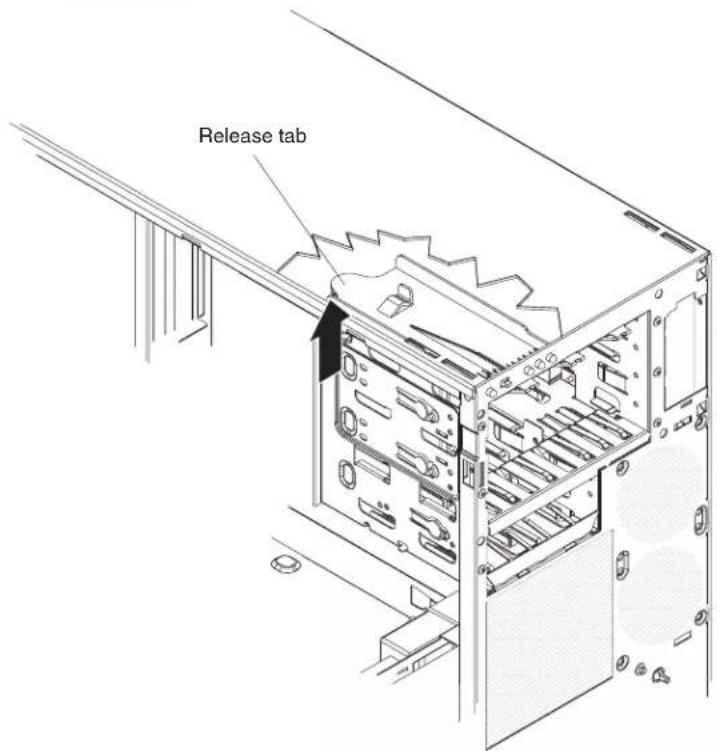
- From inside the computer, press the release tab.
- Pull the assembly toward the rear of the computer and remove it.
To replace the power/LED switch assembly, reverse the previous steps, making sure that the assembly clicks into place in the chassis.
Card/bracketassembly
Note:
- Read "Installation guidelines" on page 23.
- Read the safety notices at Appendix B, "Safety information," on page 127.
- Read "Handling static-sensitive devices" on page 23.
Complete the following steps to remove the card/bracket connector assembly:
- Turn off the computer and attached devices.
- Disconnect the power cord from the power source and from the computer; then, disconnect all external cables.
- Remove the side cover (see "Removing the side cover" on page 25.
- Remove the front bezel (see "Removing the bezel" on page 26).
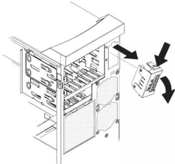
natural_image
Technical line drawing of a server rack with internal components and directional arrows indicating movement (no text or symbols)- Press the latch on the top of the assembly; this side of the assembly will detach from the chassis.
- Remove the tab on the bottom part of the assembly from the slot in the chassis.
- Pull the assembly out slightly and detach the two cables from the back of the assembly.
To install the card/bracket connector assembly, reverse the previous steps, placing the bottom tab into the slot in the chassis and then pressing the top of the assembly into place.
Speaker
Note:
- Read "Installation guidelines" on page 23.
- Read the safety notices at Appendix B, "Safety information," on page 127.
- Read "Handling static-sensitive devices" on page 23.
Complete the following steps to remove the speaker:
- Turn off the computer and attached devices.
- Disconnect the power cord from the power source and from the computer; then, disconnect all external cables.
- Remove the side cover (see "Removing the side cover" on page 25.
- Note where the speaker cable connects to the system board; then, carefully disconnect the cable from the system board.
Note: See the system service label or "System board internal connectors" on page 72 for system board connector locations.
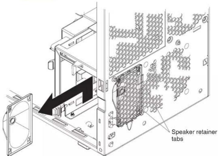
- Press the speaker retainer tabs to detach them from the chassis.
- Grasp the speaker and slide it up to clear the notches, and remove it.
To install the speaker, reverse the previous steps.
Systemboard
This section contains service information for the system board.
Systemboardoptionconnectors
The following illustration shows the system board connectors for user-installable options.
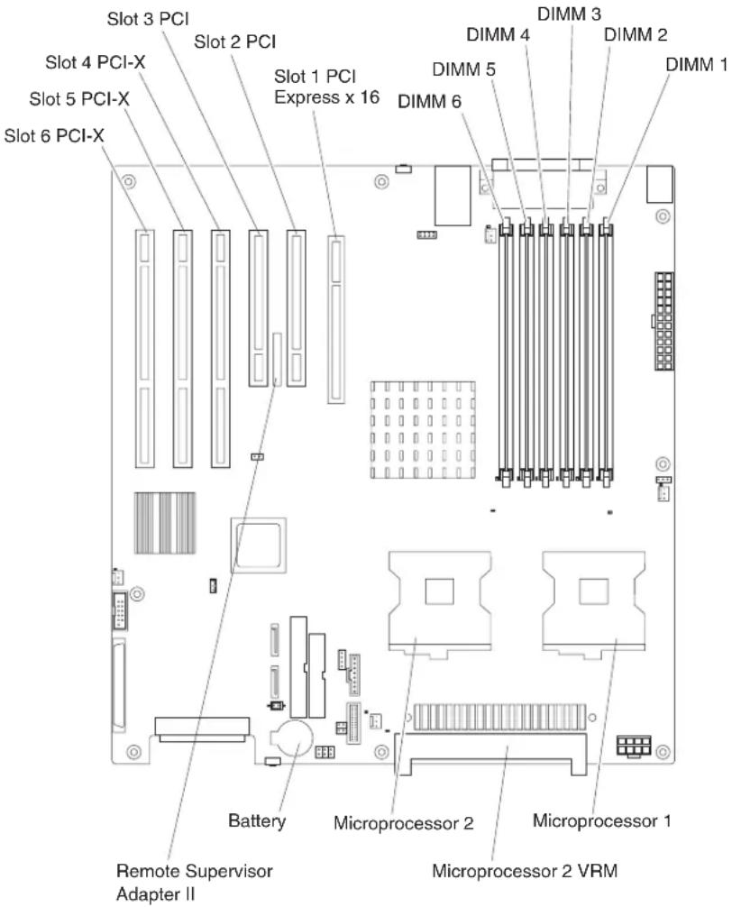
Systemboardinternalconnectors
The following illustration shows the internal connectors on the system board.

Systemboardexternalconnectors
The following illustration shows the external input/output port connectors on the system board.

SystemboarderrorLEDs
The following illustration shows the LEDs on the system board.

Systemboardjumpersandswitches
This section describes the jumpers and switches on the system board.

| JumperSettings | |
| Auto system restart (JP3) (device driver required for ASR functionality) | •Auto restart enabled (default) (no jumper)•Auto restart disabled (with jumper) |
| Configuration (JCON1) | •Normal (default) (jumper on pins 1 and 2)•Configuration (jumper on pins 2 and 3)•BIOS crisis recovery (no jumper) |
| CMOS (JCMOS1) | •Keep CMOS data (default) (jumper on pins 1 and 2)•Clear CMOS data (jumper on pins 2 and 3 with power cords removed from server) |
| Reserved (JP1, JP2) | •No jumper (default) |
| System reset (JRST1) | •Normal (default) (no jumper)•Force system reset (debug only) (with jumper) |
Removingthesystemboard
Beforeyoubegin:
- Read Appendix B, "Safety Information," on page 127.
- Review the information in “System reliability considerations” on page 23.
Notes:
- When replacing the system board, you must either update the server with the latest firmware or restore the pre-existing firmware that the customer provides on a diskette or CD image.
- Removing the system board will be easier if the server is turned on its side.
To remove the system board, complete the following steps:
- Turn off the server, if it is on.
- Disconnect the power cord from the power source and from the server; then, disconnect all external cables.
- Remove the side cover (see "Removing the side cover" on page 25).
- Rotate the drive cage to its upright position.
- Remove the microprocessor air baffle.
- Remove the adapters (see "Installing an adapter" on page 26).
- Remove the heat sinks (see "Microprocessor and heat sink" on page 60).
- Disconnect the cables on the system board, noting their locations.
Note: See the system service label or "System board internal connectors" on page 72 for system board connector locations.

- Remove the six I/O port standoff screws and set them in a safe place.
- Remove the eight heat sink retention module screws and set them in a safe place; then, remove the heat sink retention module.
- Move the retention latch toward the rear of the computer.
- Grasp the sides of the system board assembly and slide it toward the front of the computer until it detaches from the chassis; then, lift it out.
To replace the system board, reverse the previous steps.
Top/sidecover
Beforeyoubegin:
- Read Appendix B, "Safety information," on page 127
- Review the information in "System reliability considerations" on page 23.
To remove the top/side cover, complete the following steps:
- Turn off the computer, if it is on.
- Disconnect the power cord from the power source and from the computer; then, disconnect all external cables.
- Remove the side cover (see "Removing the side cover" on page 25).
- Remove the front bezel (see "Removing the bezel" on page 26).
- Remove the handle assembly (see "Handle assembly" on page 81).
- Remove the four screws from the back of the computer and put them in a safe place.
- Using a screwdriver, gently pry the cover away from the computer in the rear and slide the unit away from the computer.

natural_image
Technical line drawing of a server rack cabinet with visible internal components and mounting points (no text or labels)To replace the top/side cover, reverse the steps.
Bezel-releaselatch
Beforeyoubegin:
- Read Appendix B, "Safety information," on page 127.
- Review the information in "System reliability considerations" on page 23.
To remove the bezel-release latch, complete the following steps:
-
Turn off the computer, if it is on.
-
Disconnect the power cord from the power source and from the computer; then, disconnect all external cables.
-
Remove the side cover (see "Removing the side cover" on page 25).
-
Remove the front bezel (see "Removing the bezel" on page 26).
-
Remove the CD-ROM drive (see "CD-ROM drive" on page 61).
-
Pull down from inside the computer to release the latch tab.
-
From the underside, grasp the bezel-release latch in the center, and gently pull it back and away from the computer.
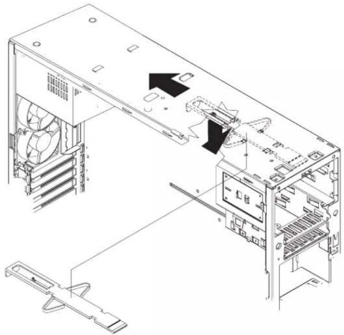
natural_image
Technical line drawing of a computer tower case with visible internal components and ventilation slots (no text or labels)To replace the bezel-release latch, complete the following steps:
- Align the bezel-release latch with the slots on the underside of the top of the chassis, and slide it into place.

natural_image
Technical line drawing of a computer tower case with visible internal components and mounting bracket (no text or labels)-
Replace the CD-ROM drive (see "Installing a drive in bay 2 or 3" on page 32).
-
Replace the front bezel (see "Replacing the bezel" on page 50).
-
Replace the side cover (see "Replacing the side cover" on page 51).
-
Connect all external cables; then, connect the power cord, and reconnect the computer to power.
-
Turn on the computer.
Handleassembly
Beforeyoubegin:
- Read Appendix B, "Safety information," on page 127.
- Review the information in "System reliability considerations" on page 23.
To remove the handle cap, complete the following steps:
- Turn off the computer, if it is on.
- Disconnect the power cord from the power source and from the computer; then, disconnect all external cables.
- Use a flathead screwdriver to gently press in and down on the tabs on the interior side wall of the handle.
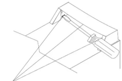
natural_image
Pure technical line drawing of a mechanical component without any text, numbers, or symbolsTab locations
- Lift up on the handle cap to separate it from the handle support.
- Turn the system back to the tower orientation; then, remove the top handle.
a. Carefully use a flat-blade screwdriver to push in the tabs inside the plastic cover on the top of the system; then, remove the plastic cover. Store the cover for possible future use.
b. Grasp the metal handle and slide it toward the rear of the computer to remove it from the computer. Store the metal handle for possible future use.
To remove the handle support, complete the following steps:
- Turn off the computer, if it is on.
- Disconnect the power cord from the power source and from the computer; then, disconnect all external cables.
- Firmly grasp the handle support, and slide it away from the front bezel.
- Lift up on the handle support to remove it from the slots in the top of the chassis.

natural_image
Pure mechanical assembly diagram showing a bracket with an upward arrow (no text or symbols)To install the handle assembly, reverse the steps.
Chapter6.Symptom-to-FRUindex
This index supports IntelliStation Z Pro Types 6223 and 6227 computers.
Notes:
- Check the configuration before you replace a CRU or FRU. Configuration problems can cause false errors and symptoms.
- For IBM devices that are not supported by this index, see the documentation for that device.
- Always start with "General checkout" on page 13.
The symptom-to-FRU index lists symptoms, errors, and the possible causes. The most likely cause is listed first. Use this symptom-to-FRU index to help you decide which FRUs to have available when servicing the computer.
The first column of the two-column tables in this index lists error codes or messages, and the last column lists one or more suggested actions or FRUs to replace. Take the action (or replace the FRU) that is suggested first in the list, and then try the computer again to see whether the problem has been corrected.
Note: Try reseating a suspected component or reconnecting a cable before replacing the component.
The POST BIOS code displays POST error codes and messages on the screen.
Beepsymptoms
Beep symptoms are short tones or a series of short tones separated by pauses (intervals without sound). See the examples in the following table.
| BeepsDescription | |
| 1-2-3•One beep | •A pause (or break)•Two beeps•A pause (or break)•Three beeps |
| 4Four continuous beeps |
One beep after successfully completing POST indicates the computer is functioning properly.
| Note: See “System replaceable units” on page 117 to determine which components should be replaced by a field service technician. | |
| Beep/symptomFRU/action | |
| 1-1-2(Microprocessor register test failed.) | •Microprocessor |
| 1-1-3(CMOS write/read test failed.) | 1. Battery2. System board |
| 1-1-4(BIOS EEPROM checksum failed.) | 1. RecoverBIOS2. System board |
| Note: See "System replaceable units" on page 117 to determine which components should be replaced by a field service technician. | |
| Beep/symptomFRU/action | |
| 1-2-1(Programmable Interval Timer failed.) | •Systemboard |
| 1-2-2(DMA page register test failed.) | •Systemboard |
| 1-2-3(DMA page register write/read failed.) | •Systemboard |
| 1-3-1(First 64K RAM test failed.) | 1. DIMM2. Memory adapter |
| 2-1-1(Secondary DMA register failed.) | •Systemboard |
| 2-1-2(Primary DMA register failed.) | •Systemboard |
| 2-1-3(Primary interrupt mask register failed.) | •Systemboard |
| 2-1-4(Secondary interrupt mask register failed) | •Systemboard |
| 2-2-2(Keyboard controller failed.) | 1. Keyboard2. System board |
| 2-2-3(CMOS power failure and checksum check failed.) | 1. Battery2. System board |
| 2-4-1(Video failed; system believed operable.) | •Systemboard |
| 3-1-1(Timer tick interrupt failed.) | •Systemboard |
| 3-1-2(Interval timer channel 2 failed.) | •Systemboard |
| 3-1-3(RAM test failed above address OFFFFH.) | 1. DIMM2. System board |
| 3-1-4(Time-Of-Day clock failed.) | 1. Battery2. System board |
| 3-2-1(Serial port failed.) | •Systemboard |
| 3-2-2(Parallel port failed.) | •Systemboard |
| 3-2-3(Math coprocessor test failed.) | 1. Optionalmicroprocessor2. Microprocessor3. System board |
| Note: See “System replaceable units” on page 117 to determine which components should be replaced by a field service technician. | |
| Beep/symptomFRU/action | |
| 3-2-4(Failure comparing CMOS memory size against actual.) | 1. DIMM2. Battery3. System board |
| 3-3-1(Memory size mismatch occurred.) | 1. DIMM2. Battery3. System board |
| 3-3-2(Critical SMBus error occurred, I2C error) | 1. Disconnectthecomputerpowercordfromoutlet,wait30seconds,andretry.2. Microprocessor3. DIMMs4. SCSI backplane5. SCSI power cable6. System board |
No-beepsymptoms
| Note: See “System replaceable units” on page 117 to determine which components should be replaced by a field service technician. | |
| No-beepsymptomFRU/action | |
| NobeepoccursduringPOST. | •Systemboard |
| Nobeep,novideo,andthe systemattentionLEDisoff. | •Systemboard |
| Nobeep,novideo,anda systemboarderrorLEDison. | •See“SystemboarderrorLEDs”onpage74. |
| BISTfailed. | •Microprocessor |
POSTerrorcodes
In the following error codes, Xcan be any number or letter.
| Note: See “System replaceable units” on page 117 to determine which components should be replaced by a field service technician. | |
| ErrorCode/symptomFRU/action | |
| 062(Three consecutive boot failures using the default configuration.) | 1. RuntheConfiguration/SetupUtilityprogram.2. Battery.3. System board.4. Microprocessor. |
| 101,102,106(Timer tick interrupt failure) | •Systemboard |
| 102(Timer 2 test failure) | •Systemboard |
| 106(Diskette controller error) | •Systemboard |
| Errorcode/symptomFRU/action | |
| 129 (Internal cache (L1) error) | 1. Optionalmicroprocessor2. Microprocessor |
| 151 (Real time clock error) | 1. Battery2. System board |
| 161 (Real time clock battery error) | 1. RuntheConfiguration/SetupUtilityprogram.2. Battery.3. System board. |
| 162 (Device configuration error)Note:Be sure to load the default settings and any additional desired settings; then, savetheconfiguration. | 1. RuntheConfiguration/SetupUtilityprogram.2. Battery.3. Failing device.4. System board. |
| 163 (Real-time clock error) | 1. RuntheConfiguration/SetupUtilityprogram.2. Battery.3. System board. |
| 164 (Memory configuration changed.) | 1. RuntheConfiguration/SetupUtilityprogram.2. DIMM.3. System board. |
| 175 (EEPROM CRC #1 damaged.) | 1. IfRemoteSupervisorAdapterllisinstalled,makesurethatthe latestfirmwareisinstalled.2. System board |
| 184 (Power-on password damaged) | 1. RuntheConfiguration/SetupUtilityprogram.2. System board. |
| 185 (Drive startup sequence information corrupted) | 1. RuntheConfiguration/SetupUtilityprogram.2. System board. |
| 187 (VPD serial number not set.) | 1. SetserialnumberintheConfiguration/SetupUtilityprogram.2. System board. |
| 188 (EEPROM CRC #2 damaged.) | 1. RuntheConfiguration/SetupUtilityprogram.2. System board. |
| 189 (An attempt made to enter the system with invalid passwords) | 1. RuntheConfiguration/SetupUtilityprogram.2. System board. |
| 196 (Microprocessor cache mismatch) | 1. Makesurethatmicroprocessorsareofsametypeandspeed.2. Microprocessor. |
| 198 (Microprocessor speed mismatch) | 1. Makesurethatmicroprocessorsareofsametypeandspeed.2. Microprocessor. |
| 199 (Microprocessors not in recommended configurations) | 1. Makesurethatmicroprocessorsareofsametypeandspeed.2. Microprocessor. |
| 201 (Memory test error.) | 1. DIMM2. System board |
| Note: See "System replaceable units" on page 117 to determine which components should be replaced by a field service technician. | |
| Errorcode/symptomFRU/action | |
| 229(Internal cache (L2) error) | 1. Microprocessor2. Optional microprocessor |
| 289(DIMM disabled by the user or system.) | 1. RuntheConfiguration/SetupUtilityprogram.2. DIMM.3. System board. |
| 301(Keyboard or keyboard controller error) | 1. Keyboard2. System board |
| 303(Keyboard controller error) | 1. ReplacethePS/2keyboardwithaUSBkeyboard.2. System board. |
| 602(Invalid diskette boot record) | 1. Diskette2. Diskette drive3. Drive cable4. System board |
| 604(Diskette drive error) | 1. RuntheConfiguration/SetupUtilityprogramanddiagnostics.2. Diskette drive.3. Drive cable.4. System board. |
| 662(Diskette drive configuration error) | 1. RuntheConfiguration/SetupUtilityprogramanddiagnostics.2. Diskette drive.3. Drive cable.4. System board. |
| 962(Parallel port configuration error) | 1. RuntheConfiguration/SetupUtilityprogram.2. System board. |
| 1162(Serial port configuration error) | •Systemboard |
| 11XX(System board serial port 1 or 2 error) | 1. RuntheConfiguration/SetupUtilityprogram.2. System board. |
| 1601(BIOS code update needed) | 1. DownloadandinstalllatestlevelofBIOScode.2. System board. |
| 1602(Cable for optional Remote Supervisor Adapter II not installed) | •Disconnectallcomputerandoptionpowercordsfromcomputer, wait30seconds,reconnect,andretry. |
| 1762(Hard drive configuration error, IDE only.) | 1. Harddiskdrive.2. Hard disk cables.3. Run the Configuration/Setup Utility program.4. System board. |
| 178X(Hard drive error, IDE only.) | 1. Harddiskcables2. Hard disk adapter3. Hard disk drive4. System board |
| Note: See “System replaceable units” on page 117 to determine which components should be replaced by a field service technician. | |
| ErrorCode/symptomFRU/action | |
| 1800(No more hardware interrupt available for PCI adapter.) | 1.RuntheConfiguration/SetupUtilityprogram.2.Remove adapter. |
| 1801(No more ROM space available for PCI adapter.) | 1.RuntheConfiguration/SetupUtilityprogram.2.Remove adapter.3.Disable the adapter BIOS and run the Configuration/Setup Utility program. |
| 1802(Unavailable I/O address for PCI adapter) | 1.StarttheConfiguration/SetupUtilityprogramandmakesurethat I/Oaddressesforalladaptersaresetcorrectly.2.Adapter.3.System board. |
| 1803(Unavailable memory address for PCI adapter) | 1.StarttheConfiguration/SetupUtilityprogramandmakesurethat memoryaddressesforallotheradaptersaresetcorrectly.2.Adapter.3.System board. |
| 1804(Unavailable memory address for PCI adapter) | 1.Removeanadaptertomakememoryaddressspaceavailable.2.Disable adapter BIOS on adapter.3.Adapter.4.System board. |
| 1805(PCI ROM error occurred) | 1.Removealladaptersandreinstalloneatatime,restartingthe computereachtime,untilthefailingadapterisdetermined; then,replacethatadapter.2.System board. |
| 1806(PCI-to-PCI bridge error occurred) | 1.Removealladaptersandreinstalloneatatime,restartingthe computereachtime,untilthefailingadapterisdetermined; then,replacethatadapter.2.System board. |
| 1807(xxxxxyyyy PCI device unresponsive or disabled by user, where xxxx=PCI vendor ID and yyyy=PCI device ID) | 1.RuntheConfiguration/SetupUtilityprogramandmakesurethe deviceisenabled.2.Adapter.3.System board. |
| 1808(Unsupported PCI device is installed) | 1.Removealladaptersandreinstalloneatatime,restartingthe computereachtime,untilthefailingadapterisdetermined; then,replacethatadapter.2.System board. |
| 1962(Drive does not contain a valid boot sector) | 1.Verifythatastartableoperatingsystemisinstalled.2.Run diagnostics.3.Hard disk drive.4.SCSI backplane.5.Cable.6.System board. |
| 2400(Video controller test failure) | 1.Videoadapter(ifinstalled)2.System board. |
| Note: See "System replaceable units" on page 117 to determine which components should be replaced by a field service technician. | |
| Errorcode/symptomFRU/action | |
| 2462(Video configuration error) | 1. Videoadapter(ifinstalled)2. System board. |
| 5962(IDE CD-ROM drive configuration error) | 1. RuntheConfiguration/SetupUtilityprogram.2. CD-ROM drive.3. CD-ROM power cable.4. IDE cable.5. System board.6. Battery. |
| 8603(Pointing-device error) | 1. Pointingdevice2. System board |
| 00012000(Machine check architecture error.) | 1. Microprocessor2. System board. |
| 00019502(Microprocessor 1 failed) | 1. Microprocessor2. System board |
| 00019xxx(Microprocessor x not functioning) | 1. Verifymicroprocessorxisinstalledcorrectly.2. Microprocessor x.3. VRM, if installed.4. System board. |
| 00151200(Unrecoverable error, microprocessor x reported IERR) | 1. Microprocessorx2. VRM3. System board |
| 00180100(No room for PCI option ROM) | 1. RuntheConfiguration/SetupUtilityprogram.2. Failing adapter.3. System board. |
| 00180200(No more I/O space available for PCI adapter.) | 1. RuntheConfiguration/SetupUtilityprogram.2. Adapter.3. System board. |
| 00180300(No more memory above 1MB for PCI adapter.) | 1. RuntheConfiguration/SetupUtilityprogram.2. Adapter.3. System board. |
| 00180400(No memory below 1 MB for PCI adapter.) | 1. RuntheConfiguration/SetupUtilityprogram.2. Adapter.3. System board. |
| 00180500(PCI option ROM checksum error.) | 1. PCladapter.2. System board. |
| 00180600(PCI device BIST failure. PCI bridge error.) | 1. RuntheConfiguration/SetupUtilityprogram.2. Adapter.3. System board. |
| 00180700(PCI device not responding.) | 1. PCladapter.2. System board. |
| Note: See “System replaceable units” on page 117 to determine which components should be replaced by a field service technician. | |
| Errorcode/symptomFRU/action | |
| 00180xxx(PCI adapter has requested resources that are not available) | 1. ReorderadaptersinPCIslots.2. Verify that boot device is positioned early in the scan order so that it is executed by POST.3. Verify that all adapters are set correctly in Configuration/Setup Utility program, changing memory settings if necessary.4. Remove an adapter to make more memory available to the adapters.5. Disable adapter BIOS on adapter (see documentation provided with adapter).6. System board. |
| 00181000(General PCI error) | 1. Adapter2. System board |
| 012980xx(Microprocessor 1 error) | 1. Verifybothmicroprocessorshavesamecachesizeandtype andthesameclockspeed.2. Download and update the BIOS code.3. Microprocessor 1.4. System board. |
| 012981xx(Microprocessor 2 error) | 1. Verifybothmicroprocessorshavesamecachesizeandtype andthesameclockspeed.2. Download and update the BIOS code.3. Microprocessor 2.4. System board. |
| I9990301(Invalid boot record on hard disk) | 1. Partitionandformatharddiskdrive.2. Cable.3. Hard disk drive.4. Adapter/system board. |
| I9990650(AC power has been restored) | 1. Checkcable.2. Check for interruption of power.3. Power cable. |
Diagnosticerrorcodes
Note: In the following error codes, if XXX is 000, 195, or 197 do not replace a FRU. The description for these error codes are:
000The test passed.
195The Esc key was pressed to abort the test.
197Warning; a hardware failure might not have occurred.
For all error codes, replace or follow the indicated FRU or action.
| Errorcode/symptomFRU/action | |
| 001-XXX-000(Failed core tests) | •Systemboard |
| 001-XXX-001(Failed core tests) | •Systemboard |
| 001-250-000(Failed system board ECC) | •Systemboard |
| 001-250-001(Failed Processor Board ECC) | •Systemboard |
| 001-292-000(Core system: failed/CMOS checksum failed) | •LoadBIOScodedefaultsandreruntest. |
| 005-XXX-000(Failed Video test) | 1. Videoadapter2. System board |
| 011-XXX-000(Failed COM1 Serial Port test) | 1. Checkloopbackplugconnectedtoexternalizedserialport.2. System board. |
| 011-XXX-001(Failed COM2 Serial Port test) | 1. Checkloopbackplugconnectedtoexternalizedserialport.2. Check cable from externalized port to system board. Should connect to serial port B on the system board (JCOM1).3. System board. |
| 014-XXX-000(Failed Parallel Port test) | •Systemboard |
| 015-XXX-001(USB interface not found, board damaged) | •Systemboard |
| 015-XXX-198(Remote Supervisor Adapter II installed) or (USB device connected during USB test) | 1. IfRemoteSupervisorAdapterllisinstalledasanoption, removeitandreruntest.Note:If Remote Supervisor Adapter II is present as a standard installation, do not remove it; the test cannot be run.2. Remove USB devices and rerun test.3. System board. |
| 020-XXX-000(Failed PCI Interface test) | •Systemboard |
| 030-XXX-000(Failed Internal SCSI interface test) | •Systemboard |
| 035-XXX-099(No adapters were found) | •Ifanadapterisinstalledre-checktheconnection. |
| 035-XXX-S99(Failed RAID test on PCI slot S, check System Error Log before replacing a FRU) | 1. RAIDadapter2. SCSI backplane3. Cable |
| 035-XXX-SNN(Check System Error Log before replacing a FRU, NN = SCSI ID of failing fixed disk) | •HarddiskwithSCSIIDNNonRAIDadapterinPCIslotS. |
| 035-253-S99(RAID adapter initialization failure) | 1. ServeRAIDAdapterinslotSisnotconfiguredproperly.Obtain thebasicandextendedconfigurationstatusandseethe ServeRAIDHardwareMaintenanceManualformore information.2. Cable.3. SCSI backplane.4. Adapter. |
| 089-XXX-001(Failed Microprocessor test) | 1. Microprocessor12. System board |
| 089-XXX-002(Failed Optional Microprocessor test) | 1. Microprocessor22. System board |
| ErrorCode/symptomFRU/action | |
| 165-060-000(Service Processor: RSA may be busy) | 1. Rerunthediagnostictest.2. Fix other error conditions that might be keeping the Remote Supervisor Adapter II busy. Refer to the error log and diagnostic panel.3. Disconnect all computer and option power cords from the computer, wait 30 seconds, reconnect, and retry.4. System board. |
| 165-198-000(Service Processor: Aborted) | 1. Rerunthediagnostictest.2. Fix other error conditions that might be keeping the Remote Supervisor Adapter II busy. Refer to the error log and diagnostic panel.3. Disconnect all computer and option power cords from the computer, wait 30 seconds, reconnect, and retry.4. System board. |
| 165-201-000(Service Processor: Failed) | 1. Disconnectallcomputerandoptionpowercordsfrom computer,wait30seconds,reconnect,andretry.2. System board. |
| 165-330-000(Service Processor: Failed) | •UpdatetothelatestROMdiagnosticlevel,andretry. |
| 165-342-000(Service Processor: Failed) | 1. MakesurethatthelatestfirmwarelevelsforRemote SupervisorAdapterllandBIOSareinstalled.2. Disconnect all computer and option power cords from computer, wait 30 seconds, reconnect, and retry.3. System board. |
| 166-198-000System Management: Aborted (Unable to communicate with RSA. It may be busy. Run the test again.) | 1. Runthediagnostictestagain.2. Correct other error conditions and retry. These include other failed system-management tests and items that are logged in the system-error log of the optional Remote Supervisor Adapter II.3. Disconnect all computer and option power cords from the computer, wait 30 seconds, reconnect, and retry.4. Remote Supervisor Adapter II.5. System board. |
| 166-201-001System Management: Failed (I2C bus error(s). See SERVPROC and DIAGS entries in event log.) | 1. Reseatthel2CcablebetweentheRemoteSupervisorAdapterll andthesystemboard.2. Reseat DIMMs.3. DIMMs.4. System board. |
| 166-250-000System Management: Failed (I2C cable is disconnected. Reconnect I2C cable between Remote Supervisor Adapter and system board.) | 1. Reseatthel2CcablebetweentheRemoteSupervisorAdapterll andthesystemboard.2. Remote Supervisor Adapter II.3. System board. |
| 166-260-000System Management: Failed (Restart RSAError. After restarting, RSA communication was lost.) | 1. Disconnectallcomputerandoptionpowercordsfromthe computer,wait30seconds,reconnect,andretry.2. Reseat the Remote Supervisor Adapter II.3. Remote Supervisor Adapter II. |
| Errorcode/symptomFRU/action | |
| 166-342-000System Management: Failed (RSA BIST indicate failed tests.) | 1. MakesurethatthelatestfirmwarelevelsforRemote SupervisorAdapterIlandBIOSareinstalled.2. Disconnect all computer and option power cords from the computer, wait 30 seconds, reconnect, and retry.3. Remote Supervisor Adapter II. |
| 180-XXX-000(Diagnostics LED failure) | •RundiagnosticLEDtestforthefailingLED. |
| 180-XXX-001(Failed Front LED panel test) | •InformationLEDpanel |
| 180-XXX-002(Failed Diagnostics LED panel test) | •Systemboard |
| 180-XXX-003(Failed system board LED test) | •Systemboard |
| 180-XXX-005(Failed SCSI Backplane LED test) | 1. SCSIbackplane2. SCSI backplane cable3. System board |
| 201-XXX-0NN(Failed Memory test, see "Installing memory modules" on page 41) | 1. DIMMLocationslots1-6whereNN=DIMMlocation.Note:NN 1=DIMM 1 NN 2=DIMM 2 NN 3=DIMM 3 NN 4=DIMM 4 NN 5=DIMM 5 NN 6=DIMM 62. System board |
| 202-XXX-001(Failed System Cache test) | 1. Microprocessor12. System board |
| 202-XXX-002(Failed System Cache test) | 1. Microprocessor22. System board |
| 206-XXX-000(Failed Diskette Drive test) | 1. Rerunthetestwithanotherdiskette.2. Diskette drive cables.3. Diskette drive.4. System board. |
| 214-XXX-000(Failed Diskette Drive test) | 1. Rerunthetestwithanotherdiskette.2. Cable.3. Diskette drive.4. System board. |
| 215-XXX-000(Failed IDE CD-ROM test) | 1. RerunthetestwithadifferentCD.2. CD-ROM drive cables.3. CD-ROM drive.4. System board. |
| 217-198-XXX(Could not establish drive parameters) | 1. Checkthecableandtermination.2. SCSI backplane.3. Hard disk drive. |
| 217-XXX-000(Failed Fixed Disk test)Note:If RAID is configured, the fixed disk number refers to the RAID logical array. | 1. FixedDisk12. System board |
| 217-XXX-001(Failed BIOS Fixed Disk test)Note:If RAID is configured, the fixed disk number refers to the RAID logical array. | 1. FixedDisk22. System board |
| 217-XXX-002(Failed Fixed Disk test)Note:If RAID is configured, the fixed disk number refers to the RAID logical array. | 1.FixedDisk32.System board |
| 217-XXX-003(Failed Fixed Disk test)Note:If RAID is configured, the fixed disk number refers to the RAID logical array. | 1.FixedDisk42.System board |
| 217-XXX-004(Failed Fixed Disk test)Note:If RAID is configured, the fixed disk number refers to the RAID logical array. | 1.FixedDisk52.System board |
| 217-XXX-005(Failed Fixed Disk test)Note:If RAID is configured, the fixed disk number refers to the RAID logical array. | 1.FixedDisk62.System board |
| 264-XXX-0NN(Failed Tape Drive test) | 1.Tapecartridge,iftheuserrantheRead/WriteTapeDrivetest (failurecodeofXXX=256).2.SCSI or power cable connected to the tape drive with SCSI ID NN.3.Tape drive with SCSI ID NN. (See the help and service information appendix of the tape drive user guide.)4.System board or SCSI controller. (Run SCSI controller diagnostic to determine if the SCSI bus is functioning properly.) |
| 264-XXX-999(Errors on multiple tape drives, see error text for more info) | •SeerrormessagesandtextinthePCDoctorerrorlogfor detailedinformationabouteachindividualtapedriveerror. |
| 301-XXX-000(Failed Keyboard test) | 1 spacecraftKeyboard2.System board |
| 405-XXX-000(Failed Ethernet test on controller on the system board) | 1.MakesurethatEthernetisnotdisabledinBIOS.2.System board. |
| 405-XXX-A0N(Failed Ethernet test on adapter in slot A) | 1.ForA=0,systemboard2.For A >0, adapter in PCI slot A |
| 415-XXX-000(Failed Modem test) | 1.CableNote:Make sure that the modem is present and attached to the computer.2.Modem3.System board |
DiagnosticerrorLEDs
| LitLEDFRU/action | |
| DIMM x (where x = DIMM 1-6; see “System board error LEDs” on page 74) | 1. DIMMx2. System board |
| Microprocessor x (where x = 1-2; see “System board error LEDs” on page 74) | 1. Microprocessorx2. System board |
| Fan x (where x = 1, 2, or 4; see “System board error LEDs” on page 74)Note:This feature is supported with optional Remote Supervisor Adapter II only. | 1. Fanx2. System board |
| Hard disk drive x (where x = 0-5)Note:LEDs are located on the front of the hot-swap hard disk drives. | 1. Harddiskdrivex2. System board |
Errorsymptoms
You can use the error symptom table to find solutions to problems that have definite symptoms.
If you cannot find the problem in the error symptom charts, run the diagnostic programs to test the computer.
If you have just added new software or a new option and the computer is not working, complete the following steps before using the error symptom charts:
- Remove the software or device that you just added.
- Run the diagnostic tests to determine whether the computer is running correctly.
- Reinstall the new software or new device.
In the following table, if the entry in the FRU/action column is a suggested action, perform that action; if it is the name of a component, reseat the component and replace it if necessary. The most likely cause of the symptom is listed first.
| Note: See Chapter 7, “Parts listing Types 6223 and 6227,” on page 115 to determine which components are replaceable by the customer (CRU), and which components must be replaced by a field service technician (FRU). | |
| CD-ROMdrive | |
| SymptomFRU/action | |
| CD-ROM drive is not recognized. | 1. Verifythat:•The IDE channel to which the CD-ROM drive is attached (primary or secondary) is enabled in the Configuration/Setup Utility program.•All cables and jumpers are installed correctly.•The correct device driver is installed for the CD-ROM drive.2. Run CD-ROM drive diagnostics.3. CD-ROM drive. |
| CD is not working properly. | 1. CleantheCD.2. Run CD-ROM diagnostics.3. CD-ROM drive. |
| CD-ROM drive tray is not working. (The computer must be powered on.) | 1. Inserttheendofapaperclipintothemanualtray-releaseopening.2. Run CD-ROM diagnostics.3. CD-ROM drive. |
| Note: See Chapter 7, "Parts listing Types 6223 and 6227," on page 115 to determine which components are replaceable by the customer (CRU), and which components must be replaced by a field service technician (FRU). | |
| Diskettedrive | |
| SymptomFRU/action | |
| The diskette drive activity LED stays lit, or the computer bypasses the diskette drive, or the diskette drive does not work. | 1. Ifthereisadisketteinthedrive,verifythat:•The diskette drive is enabled in the Configuration/Setup utility program.•The diskette is good and not damaged. (Try another diskette if you have one.)•The diskette is inserted correctly in the drive.•The diskette contains the necessary files to start the computer.•The software program is working properly.•The cable is installed correctly (in the proper orientation).2. To prevent diskette drive read/write errors, make sure that the distance between monitors and diskette drives is at least 76 mm (3 in.).3. Run diskette drive diagnostics.4. Cable.5. Diskette drive.6. System board. |
| Note: See Chapter 7, “Parts listing Types 6223 and 6227,” on page 115 to determine which components are replaceable by the customer (CRU), and which components must be replaced by a field service technician (FRU). | |
| General | |
| SymptomFRU/action | |
| Problems such as broken cover locks or indicator LEDs not working | •BrokenCRU/FRU |
| Note: See Chapter 7, “Parts listing Types 6223 and 6227,” on page 115 to determine which components are replaceable by the customer (CRU), and which components must be replaced by a field service technician (FRU). | |
| Harddiskdrive | |
| SymptomFRU/action | |
| Not all drives are recognized by the hard disk drive diagnostic test (Fixed Disk test). | 1. Removethefirstdrivenotrecognizedandtrytheharddiskdrivediagnostictestagain.2. If the remaining drives are recognized, replace the drive you removed with a new one. |
| System stops responding during hard disk drive diagnostic test. | Removetheharddiskdrivebeingtestedwhenthecomputerstopped respondingandtrythediagnostictestagain.If the hard disk drive diagnostic test runs successfully, replace the drive you removed with a new one. |
| Note: See Chapter 7, "Parts listing Types 6223 and 6227," on page 115 to determine which components are replaceable by the customer (CRU), and which components must be replaced by a field service technician (FRU). | |
| Intermittent | |
| SymptomFRU/action | |
| A problem occurs only occasionally and is difficult to detect. | 1. Verifythat:All cables and cords are connected securely to the rear of the computer and attached options.When the computer is turned on, air is flowing from the rear of the computer at the fan grill. If there is no airflow, the fan is not working. This causes the computer to overheat and shut down.Ensure that the SCSI bus and devices are configured correctly and that the last external device in each SCSI chain is terminated correctly.2. Check the system error log. |
| Note: See Chapter 7, “Parts listing Types 6223 and 6227,” on page 115 to determine which components are replaceable by the customer (CRU), and which components must be replaced by a field service technician (FRU). | |
| Keyboard,mouse,orpointing-device | |
| SymptomFRU/action | |
| All or some keys on the keyboard do not work. | 1. Verifythat:•The keyboard cable is securely connected to the system, and the keyboard and mouse cables are not reversed.•The computer and the monitor are turned on.2. Keyboard.3. System board. |
| The mouse or pointing device does not work. | 1. Verifythat:•The mouse or pointing-device cable is securely connected, and that the keyboard and mouse cables are not reversed.•The mouse device drivers are installed correctly.2. Mouse or pointing device.3. System board. |
| Memory | |
| SymptomFRU/action | |
| The amount of system memory displayed is less than the amount of physical memory installed. | 1. Verifythat:•The memory modules are seated properly.•You have installed the correct type of memory.•If you changed the memory, you updated the memory configuration with the Configuration/Setup Utility program.•All banks of memory on the DIMMs are enabled. The computer might have automatically disabled a DIMM bank when it detected a problem or a DIMM bank could have been manually disabled.2. Check POST error log for error message 289:•If the DIMM was disabled by a system-management interrupt (SMI), replace the DIMM.•If the DIMM was disabled by the user or by POST:a. Start the Configuration/Setup Utility program.b. Enable the DIMM.c. Save the configuration and restart the computer.3. DIMM.4. System board. |
| Note: See Chapter 7, “Parts listing Types 6223 and 6227,” on page 115 to determine which components are replaceable by the customer (CRU), and which components must be replaced by a field service technician (FRU). | |
| Microprocessor | |
| SymptomFRU/action | |
| The computer emits a continuous tone during POST. (The startup (boot) microprocessor is not working properly.) | 1. Verifythatthestartupmicroprocessorisseatedproperly.2. Startup microprocessor. |
| Note: See Chapter 7, “Parts listing Types 6223 and 6227,” on page 115 to determine which components are replaceable by the customer (CRU), and which components must be replaced by a field service technician (FRU). | |
| Monitor | |
| SymptomFRU/action | |
| Monitor problems (general). | Some IBM monitors have their own self-tests. If you suspect a problem with the monitor, refer to the information that comes with the monitor for adjusting and testing instructions.1. Monitor.2. Run video diagnostics. If diagnostics pass, the problem may be a video driver.3. Display adapter / system board. |
| The screen is blank. | 1. Verifythat:• The computer power cord is connected to the computer and a working electrical outlet.• The monitor cables are connected properly.• The monitor is turned on and the brightness and contrast controls are adjusted correctly.• If the computers are C2T chained together, verify that:– The C2T chain cables are securely connected to the computers.– The C2T breakout cable is connected properly.– A computer that is turned on is selected.Important:In some memory configurations, the 3-3-3 beep code might sound during POST followed by a blank display screen. If this occurs and the Boot FailCountfeature in the Start Options of the Configuration/Setup Utility program is set to Enabled(its default setting), you must restart the computer three times to force the system BIOS to reset the CMOS values to the default configuration (memory connector or bank of connectors enabled).If you have installed a Remote Supervisor Adapter II in the computer, make sure that the video cable is connected to the Remote Supervisor Adapter II.2. Make sure that damaged BIOS code is not affecting the video; see “Recovering from a POST/BIOS update failure” on page 19.3. If you have verified these items and the screen remains blank, replace:a. Monitorb. Video adapter, if installedc. System board |
| Only the cursor appears. | •See“Undeterminedproblems”onpage113. |
| The monitor works when you turn on the computer but goes blank when you start some application programs. | 1. Verifythat:• The application program is not setting a display mode higher than the capability of the monitor.• The primary monitor cable is connected to the C2T device breakout cable.• You installed the necessary device drivers for the applications.2. If you have verified these items and the screen remains blank, replace the monitor. |
| The screen is wavy, unreadable, rolling, distorted, or has screen jitter. | 1. Ifthemonitorself-testsshowthemonitorisworkingproperly,consider thelocationofthemonitor.Magnetic fields around other devices (such as transformers, appliances, fluorescent lights, and other monitors) can cause screen jitter or wavy, unreadable, rolling, or distorted screen images. If this happens, turn off the monitor. (Moving a color monitor while it is turned on might cause screen discoloration.) Then move the device and the monitor at least 305 mm (12 in.) apart. Turn on the monitor.Notes:a. To prevent diskette drive read/write errors, make sure that the distance between monitors and diskette drives is at least 76 mm (3 in.).b. Non-IBM monitor cables might cause unpredictable problems.c. An enhanced monitor cable with additional shielding is available for the 9521 and 9527 monitors. For information about the enhanced monitor cable, contact your IBM reseller or IBM marketing representative.2. Video adapter, if installed.3. System board. |
| Wrong characters appear on the screen. | 1. Ifthewronglanguageisdisplayed,updatetheBIOScodewiththecorrect language.2. Video adapter, if installed.3. System board. |
| No video. | Make sure that all cables are connected correctly and securely. If you have installed a Remote Supervisor Adapter II in the computer, make sure that the video cable is connected to the Remote Supervisor Adapter II. |
| Note: See Chapter 7, “Parts listing Types 6223 and 6227,” on page 115 to determine which components are replaceable by the customer (CRU), and which components must be replaced by a field service technician (FRU). | |
| Option | |
| SymptomFRU/action | |
| An IBM option that was just installed does not work. | 1. Verifythat:The option is designed for the computer (see the ServerProven®list at http://www.ibm.com/pc/compat).You followed the installation instructions that came with the option.The option is installed correctly.You have not loosened any other installed options or cables.You updated the configuration information in the Configuration/Setup Utility program. Whenever memory or an option is changed, you must update the configuration.2. Option you just installed. |
| An IBM option that used to work does not work now. | 1. Verifythatalloftheoptionhardwareandcableconnectionsaresecure.2. If the option comes with its own test instructions, use those instructions to test the option.3. If the failing option is a SCSI option, verify that:•The cables for all external SCSI options are connected correctly.•The last option in each SCSI chain, or the end of the SCSI cable, is terminated correctly.•Any external SCSI option is turned on. You must turn on an external SCSI option before turning on the computer.4. Failing option. |
| Note: See Chapter 7, "Parts listing Types 6223 and 6227," on page 115 to determine which components are replaceable by the customer (CRU), and which components must be replaced by a field service technician (FRU). | |
| Power | |
| SymptomFRU/action | |
| The power switch does not work and the reset button, if supported, does work. | 1. Reseattheconnector.2. Power switch card.3. System board. |
| The computer does not turn on. | 1. Verifythat:•The power cables are properly connected to the computer.•The electrical outlet functions properly.•The type of memory installed is supported by the computer, and that functional DIMMs are installed in slots 1 and 2.•If you just installed an option, remove it, and restart the computer. If the computer now turns on, you might have installed more options than the power supply supports.2. If LEDs for microprocessors or VRMs are on, verify that:a. A VRM is installed if a second microprocessor is present.b. All microprocessors have the same speed.3. Check the power supply, see “Hot-swap power-supply LED errors” on page 103. If the power supply is operating correctly:a. Service processor (baseboard management controller) error.b. Operator information card.c. System board |
| The computer does not turn off. | 1. Verify whether you are using an ACPI or non-ACPI operating system. If you are using a non-ACPI operating system:a. Press Ctrl+Alt+Delete.b. Turn off the system by holding the power-control button for 4 seconds.c. If computer fails during BIOS POST and power-control button does not work, remove the AC power cord.2. If the problem remains or if you are using an ACPI-aware operating system, suspect the system board. |
| Note: See Chapter 7, “Parts listing Types 6223 and 6227,” on page 115 to determine which components are replaceable by the customer (CRU), and which components must be replaced by a field service technician (FRU). | |
| Serialport | |
| SymptomFRU/action | |
| The number of serial ports identified by the operating system is less than the number of serial ports installed. | 1. Verifythat:•Each port is assigned a unique address by the Configuration/Setup Utility program and none of the serial ports is disabled.•The serial-port adapter, if you installed one, is seated properly.2. Failing serial port adapter. |
| A serial device does not work. | 1. Verifythat:•The device is compatible with the computer.•The serial port is enabled and is assigned a unique address.•The device is connected to the correct port (see “Input/output connectors” on page 53).2. Failing serial device.3. Serial adapter, if installed.4. System board. |
| Note: See Chapter 7, "Parts listing Types 6223 and 6227," on page 115 to determine which components are replaceable by the customer (CRU), and which components must be replaced by a field service technician (FRU). | |
| ServerGuideSetupandInstallationCD | |
| SymptomFRU/action | |
| The ServerGuideSetupand InstallationCD will not start. | ·Verifythattheserverissupportedandhasastartable(bootable)CD-ROM drive.·If the startup (boot) sequence settings have been altered, ensure that the CD-ROM drive is first in the startup sequence.·If more than one CD-ROM drive is installed, ensure that only one drive is set as the primary drive. Start the CD from the primary drive. |
| The SCSI RAID program cannot view all installed drives, or the NOS cannot be installed. | ·VerifythattherearenoduplicateSCSIIDsorIRQassignments.·Verify that the hard disk drive is connected properly. |
| The operating system installation program continuously loops. | ·Makemorespaceavailableontheharddisk. |
| The ServerGuide program will not start the operating-system CD. | ·Verifythattheoperating-systemCDyouhaveissupportedbythe ServerGuide program. See the ServerGuide Setup and Installation CD label for a list of supported operating system versions. |
| The operating system cannot be installed; the option is not available. | ·Verify that the operating system is supported on the computer. If the operating system is supported, either there is no logical drive defined (SCSI RAID systems) or the ServerGuide System Partition is not present. Run the ServerGuide program, and ensure that setup is complete. |
| Note: See Chapter 7, “Parts listing Types 6223 and 6227,” on page 115 to determine which components are replaceable by the customer (CRU), and which components must be replaced by a field service technician (FRU). | |
| Software | |
| SymptomFRU/action | |
| Suspected software problem. | 1. Todetermineifproblemsarecausedbythesoftware,verifythat:•The computer has the minimum memory needed to use the software. For memory requirements, see the information that comes with the software.Note:If you have just installed an adapter or memory, you might have a memory address conflict.•The software is designed to operate on the computer.•Other software works on the computer.•The software that you are using works on another system.If you received any error messages when using the software program, see the information that comes with the software for a description of the messages and suggested solutions to the problem.2. If you have verified these items and the problem remains, contact the place of purchase. |
Hot-swappower-supplyLEDerrors
Use the information in this section to solve power-supply problems.
Note: The minimum configuration required for the dc good light to be lit is:
•Power supply
•Power cage assembly, if installed.
- System board.
| Note: See "System replaceable units" on page 117 to determine which components should be replaced by a field service technician. | |||
| ACgood LED | DCgood LEDDescription | FRU/action | |
| Off Off No power to system or ac problem. | 1.Checkacpowertothesystem.2.Power supply. | ||
| On Off Standby mode or dc problem. | 1.ChecksystemboardcableconnectorsJPWR1andJPWR2.Power-on the server. If the dc good LED is lit, press Ctrl+Alt+Delete. Watch the screen for any POST errors. Check the system error log for any listed problems. If the system starts with no errors:a. Power switch assemblyb. System board2.Remove the adapters and disconnect the cables and power connectors to all internal and external devices. Turn on the system. If the dc good LED is lit, replace the adapters and devices one at a time until you isolate the problem.3.Power supply.4.Power cage assembly, if installed.5.System board. | ||
| On On Power is working | properly. | N/A | |
Serviceprocessorerrorcodes
When viewed in the system-error log, the Remote Supervisor Adapter II messages will appear as text descriptions. To determine a possible error condition for the Remote Supervisor Adapter II, see the system-error log (see "Starting the diagnostic programs and viewing the test log" on page 17).
SCSlerrorcodes
| ErrorcodeFRU/action | |
| AllSCSIErrorsOne or more of the following might be causing the problem:A failing SCSI device (adapter, drive, controller)An improper SCSI configuration or SCSI termination jumper settingDuplicate SCSI IDs in the same SCSI chainA missing or improperly installed SCSI terminatorA defective SCSI terminatorAn improperly installed cableA defective cable | 1. ExternalSCSIdevicesmustbeturnedonbeforeyou turnonthecomputer.2. Make sure that the cables for all external SCSI devices are connected correctly.3. If you have attached an external SCSI device to the computer, make sure the external SCSI termination is set to automatic.4. Make sure that the last device in each SCSI chain is terminated correctly.5. Make sure that the SCSI devices are configured correctly. |
ServeRAIDerrorcodes
In the following error codes, x can be any number or letter.
| Note: See “System replaceable units” on page 117 to determine which components should be replaced by a field service technician. | |
| Errorcode/symptomFRU/action | |
| 1xxx (Microcode checksum error) | 1. ServeRAID controller |
| 2xxx (Code DRAM error) | 1. Install download jumpers, flash latest level BIOS and firmware for controller. Remove jumpers.2. ServeRAID controller. |
| 3000-31xx(Code DRAM error) | 1. Install download jumpers, flash latest level BIOS and firmware for controller. Remove jumpers.2. ServeRAID controller. |
| 3200 (Code DRAM error) | 1. Install download jumpers, flash latest level BIOS code and firmware for controller. Remove jumpers.2. ServeRAID controller. |
| 3300 (ServeRAID-5i only) | 1. Install ServeRAID-5i controller in an extended PCI expansion slot. See the documentation that came with the server for more information. |
| 3E20 (ServeRAID-5i only) | 1. Remove the ServeRAID-5i controller from its slot and install it in the proper PCI option slot.2. Verify that the ServeRAID-5i controller is supported in this server.3. ServeRAID-5i controller.4. System board. |
| 3E2x | 1. Reseat the ServeRAID controller.2. Flash latest level of BIOS code and firmware for controller.3. ServeRAID-5i controller.4. Integrated RAID controller on serve). |
| 4xxx thru 5xxx (Code DRAM error) | 1. Install download jumpers, flash latest level BIOS code and firmware for controller; then, remove jumpers.2. ServeRAID controller. |
| 6xxx (Cache DRAM error)(ServeRAID-4H only) | 1. Reseat daughter card.2. Install download jumpers, flash latest level BIOS code and firmware for controller; then, remove jumpers.3. ServeRAID controller. |
| 7xxx thru 8xxx (Host/local PCI bus interface error) | 1. Flash latest level of BIOS code and firmware for controller.2. If ServeRAID-4x controller, replace controller.3. If ServeRAID-5i controller, integrated RAID controller on the computer. |
| 9003 | 1. Flash latest level of BIOS code and firmware for controller.2. Confirm that this controller is a supported option for this system.3. ServeRAID controller.4. Integrated RAID controller on the computer). |
| 9xxx thru BZxx (SCSI bus error caused by cables, termination, defective drives, etc.). Z refers to the specific channel or channels that cause the error. | 1. Follow indications at “POST (ISPR) error procedures” on page 107. Follow those instructions before continuing with the next steps listed in this index.2. SCSI cable.3. SCSI backplane.4. Hard disk drive.5. ServeRAID controller. |
| EFFE (Firmware code corrupt or download jumpers are in place) | 1. Flash latest level BIOS and firmware for controller; then, remove jumpers.2. ServeRAID controller. |
| FFFF or other code not listed | 1. Follow indications at “POST (ISPR) error procedures” on page 107.2. SCSI cable.3. SCSI backplane.4. Hard disk drive.5. ServeRAID controller. |
POST(ISPR)errorprocedures
Use the ISPR error procedures to help you solve ServeRAID problems. A complete list of error codes is listed at "ServeRAID error codes" on page 105.
Note: Where the ISPR error procedures refer to a SCSI backplane, see the chapter of this publication that concerns service replaceable units.
EF10(Default ISPR)
- No ISPR error present.
9ZxxthroughBZxx(SCSI bus error caused by cables, termination, defective drives, or similar problem)
- Isolate between SCSI subsystem and controller by disconnecting all SCSI cables from suspect card, and restart.
Attention: Do not press F5. Doing so changes the computer configuration.
If an ISPR error is still present, perform the following actions until the error is no longer present:
a. Reseat the controller
b. Replace the controller
Notes:
a. SCSI channel cable details, if any, appear elsewhere in this publication.
b. The adapter/controller detects a configuration change. Do not select Save Changes. Instead, press F10 to bypass any options to this effect.
- If ISPR error is EF10 after disconnecting cables:
a. Identify which channel is causing the error by the second digit (Z) of the original ISPR code as indicated in the following table.
Note: ServeRAID-4H controllers have 4 channels; ServeRAID-4L and -4Lx controllers have only one channel; and ServeRAID-4M and -4Mx controllers have 2 channels. ServeRAID-5i and ServeRAID-6i controllers have no channels. The ServeRAID-5i and ServeRAID-6i use the channel connectors of the onboard integrated SCSI controller.
Table4.SCSIdentifier
| SCSIChannelCode(z)Descriptions | |
| 1 Channel 1 | |
| 2 Channel 2 | |
| 3 Channel 1 and 2 | |
| 4 Channel 3 | |
| 5 Channel 1 and 3 | |
| 6 Channel 2 and 3 | |
| 7 Channel 1, 2, and 3 | |
| 8 Channel 4 | |
| 9 Channel 1 and 4 | |
| A Channel 2 and 4 | |
| B Channel 1, 2, and 4 | |
| C Channel 3 and 4 | |
| D Channel 1, 3, and 4 | |
| E Channel 2, 3, and 4 | |
| F Channel 1, 2, 3, and 4 | |
b. Confirm that the channels identified from the error in step 2a on page 107 are the cause of the error by verifying that the error presents itself only when the offending channel is reconnected.
c. Check termination of identified channel.
Note: SCSI channel termination details, if any, appear elsewhere in this publication.
d. Check for proper backplane jumper configuration.
Note: SCSI channel jumper details, if any, appear elsewhere in this publication.
e. Check for proper cabling configuration in systems that use hard disk drive status cables. Reconnect all cables removed in step 1 on page 107.
f. Disconnect one drive at a time attached to the channel identified in step 2a on page 107, then, restart to determine which drive is causing the error.
g. Replace SCSI cable.
h. Replace SCSI backplane.
FFFForothercodenotlisted
-
Place download jumpers on the controller and try to flash the firmware code to the card.
-
Isolate between SCSI subsystem and controller by disconnecting all SCSI cables attached to the suspect card, and restart.
Attention: Do not press F5. Doing so changes the computer configuration.
If ISPR code is EF10 after disconnecting cables, follow these steps until the error is eliminated:
a. Identify which channel is causing the error by reconnecting cables one at a time and restarting until the error returns.
b. Check termination of identified channel in step 2a.
Note: SCSI channel termination details, if any, appear elsewhere in this publication.
c. Disconnect one drive at a time attached to channel identified in step 2a and restart each time to determine which drive is causing the problem.
d. Replace SCSI cable attached to channel identified in step 2a.
e. Replace backplane attached to channel identified in step 2a.
- If original ISPR code is still present after disconnecting all SCSI cables and restarting, perform the following actions until the error is no longer present:
- Reseat the controller
-Replace the controller
Temperatureerrormessages
| Note: See “System replaceable units” on page 117 to determine which components should be replaced by a field service technician. | |
| MessageAction | |
| DASDOverTemperature (level-critical; direct access storage device bay xwas over temperature) | ·Ensurethatthesystemisbeingproperlycooled;see “Systemreliability considerations” on page 23. |
| DASDOverrecommendedTemperature (sensorx) (level-warning; DASD bay xhad over temperature condition) | ·Ensurethatthesystemisbeingproperlycooled;see “Systemreliability considerations” on page 23. |
| DASDunderrecommendedtemperature (sensorx)(level-warning; direct access storage device bay xhad under temperature condition) | ·Ambienttemperaturemustbewithinnormaloperatingspecifications;see “Features and specifications” on page 3. |
| DASDOverTemperature (level-critical; sensor for DASD1 reported temperature over recommended range) | ·Ensurethatthesystemisbeingproperlycooled;see “Systemreliability considerations” on page 23. |
| PowersupplyxTemperatureFault (level-critical; power supply xhad over temperature condition) | 1. Ensuresystemisbeingproperlycooled;see “System reliability considerations” on page 23.2. Power supply x. |
| Systemboardisoverrecommended temperature (level-warning; system board is over recommended temperature) | 1. Ensuresystemisbeingproperlycooled; see “System reliability considerations” on page 23.2. System board. |
| Systemboardisunderrecommended temperature (level-warning; system board is under recommended temperature) | ·Ambienttemperaturemustbewithinnormaloperatingspecifications;see “Features and specifications” on page 3. |
| SystemovertemperatureforCPUx (level-warning; CPU x reporting over temperature condition) | ·Ensuresystemisbeingproperlycooled;see “System reliability considerations” on page 23. |
| SystemunderrecommendedCPUx temperature(level-warning; system reporting under temperature condition for CPU x) | ·Ambienttemperaturemustbewithinnormaloperatingspecifications; see “Features and specifications” on page 3. |
Fanerrormessages
| Note: See “System replaceable units” on page 117 to determine which components should be replaced by a field service technician. | |
| MessageAction | |
| Fanxfailure(level-critical; fan xhad a failure) | 1. Checkconnectionstofanx.2. Replace fan x. |
| Fanxfault(level-critical; fan xbeyond recommended RPM range) | 1. Checkconnectionstofanx.2. Replace fan x. |
| Fanxoutsiderecommendedspeed action | •Replacefanx. |
Powererrormessages
| Note: See “System replaceable units” on page 117 to determine which components should be replaced by a field service technician. | |
| MessageAction | |
| Powersupplyxcurrentsharefault (level-critical; excessive current demand on power supply x) | •Replacepowersupplyx. |
| PowersupplyxDCgoodfault (level-critical; power good signal not detected for power supply x) | •Replacepowersupplyx. |
| Powersupplyxtemperaturefault | •Replacepowersupplyx. |
| Powersupplyxremoved | •Noactionrequired-informationonly. |
| Powersupplyxfanfault(level-critical; fan fault in power supply x) | •Replacepowersupplyx. |
| Powersupplyx12Vfault(level-critical; overcurrent condition detected) | •See“Powercheckout”onpage22. |
| Powersupplyx3.3Vfault(level-critical; 3.3 V power supply xhad an error) | •See“Powercheckout”onpage22. |
| Powersupplyx5Vfault(level-critical; 5 V power supply xhad an error) | •See“Powercheckout”onpage22. |
| Systemrunningnon-redundantpower (level-noncritical; system does not have redundant power) | 1. Addanotherpowersupply.2. Remove options from system.3. System can continue to operate without redundancy protection if steps1 and 2 are not followed. |
| Systemunderrecommendedvoltageforx (level-warning; indicated voltage supply under nominal value; value for xcan be +12, -12, or +5) | 1. Checkconnectionstothepowersubsystem.2. Power supply.3. Power cage assembly, if installed. |
Systemshutdown
See the following tables when experiencing system shutdown related to voltage or temperature problems.
Voltage-relatedsystemshutdown
| Note: See “System replaceable units” on page 117 to determine which components should be replaced by a field service technician. | |
| MessageAction | |
| Systemshutoffduetoxcurrentover maxvalue(level-critical; system drawing too much current on voltage xbus) | •See“Powercheckout”onpage22. |
| SystemshutoffduetoxVovervoltage (level-critical; system shutoff due to x supply over voltage) | 1. Checkthepower-supplyconnectors.2. Power supply.3. Power cage assembly, if installed. |
| SystemshutoffduetoxVundervoltage (level-critical; system shutoff due to x supply under voltage) | 1. Checkthepower-supplyconnectors.2. Power supply.3. Power cage assembly, if installed. |
| SystemshutoffduetoVRMxover voltage | •ReplaceVRMx. |
| Systemshutoffduetoexcessive(<240 VA)loading | 1. See“Powercheckout”onpage22.2. Cycle ac on/off. |
Temperature-relatedsystemshutdown
| Note: See “System replaceable units” on page 117 to determine which components should be replaced by a field service technician. | |
| MessageAction | |
| Systemshutoffduetoboardover temperature(level-critical; board is over temperature) | 1.Ensurethatthesystemisbeingproperlycooled;see “Systemreliability considerations” on page 23.2.Replace board. |
| SystemshutoffduetoCPUxover temperature(level-critical; CPU xis over temperature) | 1.Ensurethatthesystemisbeingproperlycooled;see “Systemreliability considerations” on page 23.2.Replace microprocessor x. |
| SystemshutoffduetoCPUxunder temperature(level-critical; CPU xis under temperature) | •Ambienttemperaturemustbewithinnormaloperatingspecifications;see “Features and specifications” on page 3. |
| SystemshutoffduetoDASDtemperature (sensorx)(level-critical; DASD area reported temperature outside recommended operating range) | •Ensurethatthesystemisbeingproperlycooled;see “Systemreliability considerations” on page 23. |
| Systemshutoffduetohighambient temperature(level-critical; high ambient temperature) | •Ambienttemperaturemustbewithinnormaloperatingspecifications;see “Features and specifications” on page 3. |
| Systemshutoffduetosystemboard undertemperature(level-critical; system board is under temperature) | •Ambienttemperaturemustbewithinnormaloperatingspecifications;see “Features and specifications” on page 3. |
Harddiskdrivecheckout
| Note: See “System replaceable units” on page 117 to determine which components should be replaced by a field service technician. | |
| MessageAction | |
| Harddrivexremovaldetected (level-critical; hard drive xhas been removed) | •Informationonly;takeactionasappropriate. |
Hostbuilt-inselftest(BIST)
| Note: See “System replaceable units” on page 117 to determine which components should be replaced by a field service technician. | |
| MessageAction | |
| Hostfail(level-informational; built-in self-test for the host failed) | 1. Reseatthemicroprocessor.2. Replace the microprocessor. |
Busfaultmessages
| Note: See “System replaceable units” on page 117 to determine which components should be replaced by a field service technician. | |
| BusfaultmessagesMessageAction | |
| Failurereading12Cdevice.Check devices on bus 0. | 1. Ifinstalled,reseatthel2CcablebetweenRSA2andtheRSA2connectoronthesystemboard.2. DIMMs.3. System board. |
| Failurereading12Cdevice.Check devices on bus 1. | 1. Reseatthel2Ccablebetweenheoperatorinformationpanelandsystemboard.2. Operator information panel.3. System board. |
| Failurereading12Cdevice.Check devices on bus 2. | 1. Reseatthecablebetweensystemboardandthepowersupply(powercageassembly,ifinstalled)(JPWR1,JPWR2).2. Power cage assembly, if installed.3. Power supply.4. System board. |
| Failurereading12Cdevice.Check devices on bus 3. | 1. ReseatthecablebetweenheSCSIbackplaneandconnectoronsystemboard.2. SCSI backplane.3. System board. |
| Failurereadingl2Cdevice.Check device on bus 4. | •Systemboard |
Undeterminedproblems
Use the information in this section if the diagnostic tests did not identify the failure, the devices list is incorrect, or the system is inoperative.
Damaged data in CMOS memory or damaged BIOS code can cause undetermined problems. To reset the CMOS data, use the CMOS recovery jumper to override the power-on password and clear the CMOS memory; see "Erasing a lost or forgotten password (clearing CMOS)" on page 20. If you suspect that the BIOS code is damaged, see "Recovering from a POST/BIOS update failure" on page 19.
Check the LEDs on all the power supplies. If the LEDs indicate the power supplies are working correctly, complete the following steps:
- Turn off the computer.
- Be sure the computer is cabled correctly.
- Remove or disconnect the following devices (one at a time) until you find the failure (turn on the computer and reconfigure each time):
•Any external devices - Surge suppressor device (on the computer)
•Modem, printer, mouse, or non-IBM devices
•Each adapter
•Drives
• Memory modules (minimum requirement = 512 MB (2 banks of 256 MB DIMMs))
Note: Minimum operating requirements are:
a. One power supply
b. Power cage assembly, if installed
c. System board
d. One microprocessor
e. Memory module (with a minimum of two 256 MB DIMMs)
- Turn on the computer. If the problem remains, suspect the following FRUs in the order listed:
•Power supply
•Power cage assembly, if installed
- System board
Notes:
-
If the problem goes away when you remove an adapter from the system and replacing that adapter does not correct the problem, suspect the system board.
-
If you suspect a networking problem and all the system tests pass, suspect a network cabling problem external to the system.
Problem determination tips
Because of the variety of hardware and software combinations that can be encountered, use the following information to assist you in problem determination. If possible, have this information available when requesting assistance from Service Support and Engineering functions.
•Machine type and model
- Microprocessor or hard disk upgrades
- Failure symptom
- Do diagnostics fail?
– What message appears in the diagnostics log?
– What, when, where, single, or multiple systems?
– Is the failure repeatable? - Has this configuration ever worked?
- If it has been working, what changes were made prior to it failing?
– Is this the original reported failure?
• Diagnostics version
- Type and version level
•Hardware configuration
- Print (print screen) configuration currently in use
- BIOS level
- Operating system software
- Type and version level
Note: To eliminate confusion, identical systems are considered identical only if they:
- Are the exact machine type and models
•Have the same BIOS level - Have the same adapters/attachments in the same locations
- Have the same address jumpers/terminators/cabling
- Have the same software versions and levels
- Have the same diagnostics code (version)
- Have the same configuration options set in the system
- Have the same setup for the operation system control files
Comparing the configuration and software set-up between “working” and “non-working” systems will often lead to problem resolution.
Chapter7.PartslistingTypes6223and6227
This parts listing supports the IntelliStation Z Pro Types 6223 and 6227. To check for an updated parts listing on the Web, complete the following steps:
- Go to http://www.ibm.com/support/
- Under Search technical support, type 6223 or 6227 and click Search.
- Under Document type, select Partsinformation and click Go.
System
The major components of the IntelliStation Z Pro Types 6223 and 6227 are shown in the following illustration.
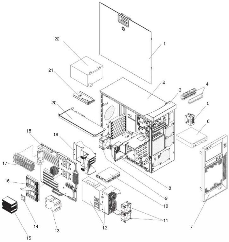
Systemreplaceableunits
Note:
- Field replaceable units (FRUs) must be serviced only by qualified field service technicians.
- Customer replaceable units (CRUs) can be replaced by the customer. Tier 1 CRUs and Tier 2 CRUs are described in the IBM “Statement of Limited Warranty” (at “Part 3 – Warranty Information”), which is in the Installation Guide.
| Index | SystemIntelliStationZPro(Types6223and6227) | CRUNo.(Tier1) | CRUNo.(Tier2) | FRUNo. |
| 1 Cover | , side/top (all models) 13N2447 | |||
| 2 Chassis, staked (all models) 13N2443 | ||||
| 3 Handle cap assembly 13N2996 | ||||
| 4 Shield kit, 3.5" and 5.25" (all models) 13N2997 | ||||
| 5 Card | IEEE 1394 (FireWire) (all models) 39Y9700 | |||
| 6 | CD-ROM, 48x read/write (primary) (models 11x, 21x, 22x, 28x, 29x, B1x, B2x) | 26K5376 | ||
| 6 CD-ROM, 48X read/write (optional) 71P7347 | ||||
| 6 CD-ROM, 48X read/write (optional) 71P7349 | ||||
| 6 | CD-ROM, half-high combo (primary) (models 12x, 14x, 23x, 24x, 26x, 27x, 2T6, 31x, 3Bx, 41x, 42x, 43x, 4Bx, 5Bx, 51x, 52x, 53x, 5Gx, 64x, 68x, 6Bx, 6Cx, 6Dx, 72x, 73x, 75x, 76x, 78x, 7Bx, 7Cx, 7Dx, 7Gx, 98x, B3x, B4x | 39M0135 | ||
| 6 | CD-ROM, half-high (alternate for 39M0135) (models 12x, 14x, 23x, 24x, 26x, 27x, 2T6, 31x, 3Bx, 41x, 42x, 43x, 4Bx, 5Bx, 51x, 52x, 53x, 5Gx, 64x, 58x, 6Bx, 6Cx, 6Dx, 72x, 73x, 75x, 76x, 78x, 7Bx, 7Cx, 7Dx, 7Gx, 98x, B3x, B4x | 26K5429 | ||
| 6 | DVD, 48X combo (alternate for 39M0135) (models 12x, 14x, 23x, 24x, 26x, 27x, 2T6, 31x, 3Bx, 41x, 42x, 43x, 4Bx, 5Bx, 51x, 52x, 53x,5Gx, 64x, 68x, 6Bx, 6Cx, 6Dx, 72x, 73x, 75x, 76x, 78x, 7Bx, 7Cx, 7Dx, 7Gx, 98x, B3x, B4x) | 26K5379 | ||
| 6 DVD | 48X combo (optional) 26K5381 | |||
| 6 CD-ROM, 48X (optional) 71P7375 | ||||
| 6 CD-ROM, 48X (optional) 71P7385 | ||||
| 6 CD-ROM, 16/48X (optional) 26K5435 | ||||
| 6 | CD-ROM, 48X half high, read/write (models 11x, 21x, 22x, 28x, 29x, B1x, B2x, 11x) | 26K5449 | ||
| 6 DVD | half high () 39M3515 | |||
| 6 | CD-ROM, 48X half high, read/write (models 10x, 3Gx, 6Gx, 98x, 99x, A0x) | 39M3511 | ||
| 6 | CD-ROM, 48X half high (primary) (models 10x, 3Gx, 6Gx, 98x, 99x, A0x) | 42C0953 | ||
| 6 | CD-ROM, 48X half high (alternate for 42C0953) (models 10x, 3Gx, 6Gx, 98x, 99x, A0x) | 39M3509 | ||
| 7 Beze | front (all models) 13N2445 | |||
| 8 Pivot | ng duct/fan assembly, DASD cage (all models) 13N2995 | |||
| 9 | Fan assembly, 92X38 (all models except 3Bx, 4Bx, 5Bx, 5Cx, 6Bx, 6Cx, 6Dx, 7Bx, 7Cx, 7Dx) | 13N2967 | ||
| 9 | Fan assembly, 92X38 (models 3Bx, 4Bx, 5Bx, 5Cx, 6Bx, 6Cx, 6Dx, 7Bx, 7Cx, 7Dx) | 39Y9788 | ||
| 10 | Hard disk drive, 80GB (models 10x, 11x, 12x, 21x, 23x, 31x, 41x, 43x, 51x, 53x, 72x, 73x, 75x, 98x, A0x, B1x, B3x) | 71P7293 | ||
| 10 | Hard disk drive, 73.4GB SCSI 10K RPM model 14x, 22x, 24x, 26x, 27x, 28x, 29x, 42x, 52x, 64x, 68x, 76x, 78x, B2x, B4x) | 24P3706 | ||
| 10 Hard | disk drive, 36.4GB SCSI 10K RPM (model 99x) 24P3704 | |||
| 10 Hard | disk drive, 36.4GB 15K NHS (model CTO) 39R7326 | |||
| 10 | Hard disk drive, 160GB SCSI 10K RPM (models 3Bx, 4Bx, 5Bx, 5Gx, 6Bx, 7Bx, 7Gx) | 39M4507 | ||
| 10 Hard | disk drive, 160GB SATA (models AC1, MC1, CTO) 40K6871 | |||
| 10 Hard | disk drive, 146.8 SCSI 10K RPM (optional) 24P3708 | |||
| 10 Hard | disk drive, 36.4GB SCSI 15K RPM (optional) 24P3725 | |||
| 10 Hard | disk drive, 73GB (model 7Dx) 39R7328 | |||
| 10 Hard | disk drive, 73GB 15K NHS (models 5Cx, 6Cx, 6Dx, 7Cx) 39R7320 | |||
| 10 Hard | disk drive, 73.4GB SCSI 15K RPM (optional) 24P3727 | |||
| 10 Hard | disk drive, 146GB 15K NHS (model CTO) 39R7322 | |||
| 10 Hard | disk drive, 146GB 15K NHS (models AC1, MC1, CTO) 39R7330 | |||
| 10 Hard | disk drive, 146GB 10K NHS (model CTO) 39R7324 | |||
| 11 | Fan assembly, 80X38, S/R (models 12x, 26x, 27x, 31x, 41x, 42x, 43x, 51x, 52x, 53x, 64x, 68x, 72x, 76x, 78x) | 25R8830 | ||
| 11 | Fan assembly, 80X38, S/R (models 3Bx, 4Bx, 5Bx, 5Cx, 6Bx, 6Cx, 6Dx, 7Bx, 7Cx, 7Dx) | 39Y9786 | ||
| 11 | Fan assembly, 80X38, S/R (models 3Bx, 4Bx, 5Bx, 5Cx, 6Bx, 6Cx, 6Dx, 7Bx, 7Cx, 7Dx) | 39Y9787 | ||
| 11 | Fan assembly, 80X38, S/R (all models except 12x, 26x, 27x, 31x, 41x, 42x, 43x, 51x, 52x, 53x, 64x, 68x, 72x, 76x, 78x) | 13N2966 | ||
| 12 Air duct, microprocessor (all models) 13N2448 | ||||
| 13 | Dummy heat sink assembly (models 01x, 10x, 11x, 12x, 21x, 22x, 23x, 24x, 28x, 26x, 27x, 29x, 31x, 41x, 42x, 43x, 51x, 52x, 53x, 64x, 68x, 72x, 75x, 76x, 78x, 75x, 98x, 99x, B1x, B2x, B3x, A0x) | 26K6065 | ||
| 13 | Dummy heat sink assembly (models 3Bx, 4Bx, 5Bx, 6Bx, 6Cx, 6Dx, 7Bx, 7Cx, 7Dx) | 40K6482 | ||
| 14 | Microprocessor, 800/3.4MHz 1MB (models 10x, 11x, 12x, 14x, 98x, 99x, A0x) | 90P1227 | ||
| 14 | Microprocessor, 800/3.6MHz-1M (models 21x, 22x, 23x, 24x, 26x, 27x, 28x, 29x, 2T6, B1x, B2x, B3x, B4x) | 90P1229 | ||
| 14 Microprocessor, 800/3.0MHz-2M (models 31x, 3Bx) 13M8293 | ||||
| 14 Microprocessor, 800/3.2MHz-2M (models 41x, 42x, 43x, 4Bx) 13M8294 | ||||
| 14 | Microprocessor, 800/3.4MHz-2M (models 51x, 52x, 53x, 5Bx, 5Cx) | 13M8295 | ||
| 14 Microprocessor, 800/3.6MHz-2M (models 64x, 68x, 6Bx, 6Cx) 13M8296 | ||||
| 14 | Microprocessor, 800/3.8MHz-2M (models 72x, 73x, 75x, 76x, 78x) | 39R7571 | ||
| 15 | Heat sink (models 01x, 11x, 12x, 21x, 31x, 41x, 43x, 51x, 53x, 72x, 75x, 98x, 99x, A0x, B1x, B2x, B3x) | 13N1625 | ||
| 15 | Heat sink (models 12x, 26x, 27x, 31x, 41x, 42x, 43x, 51x, 52x, 53x, 64x, 68x, 72x, 76x, 78x) | 25R8832 | ||
| 16 Tool-less retention module assembly, left (all models) 26K6146 | ||||
| 16 Tool-less retention module assembly, right (all models) 26K6147 | ||||
| 17 Memory, 256MB ECC DDR II 400 (models 10x, 98x, 99x, A0x) 90P1123 | ||||
| 17 | Memory, 1GB ECC DDR II 400 (models 27x, 43x, 51x, 53x, 64x, 68x, 72x, 73x, 75x, 76x, 78x) | 73P2870 | ||
| 17 | Memory DIMM, 512MB PC2-3200 DIMM (models 21x, 22x, 23x, 24x, 28x, 29x, 11x, 14x, 12x, 26x, 31x, 41x, 42x, 52x, 3Gx, 6Gx, B1x, B2x, B3x ,B4x) | 13N1424 | ||
| 17 Memory DIMM, 512MB PC2-3200 (model 3Bx) 39M5817 | ||||
| 17 | Memory DIMM, 1GB PC2-3200 (models 27x, 43x, 4Bx, 51x, 53x, 5Bx, 5Cx, 5Gx, 64x, 68x, 6Bx, 6Cx, 6Dx, 72x, 73x, 72x, 73x, 75x, 76x, 78x, 7Bx, 7Cx, 7Dx, 7Gx) | 39M5808 | ||
| 17 Memory DIMM, 1GB PC2-3200 (models AC1, MC1, CTO) 39M5811 | ||||
| 17 Memory 4GB PC2-3200 (optional) 41Y2815 | ||||
| 18 System board and tray assembly (all models) 26K8598 | ||||
| 18 | System board and tray assembly (models 3Bx, 4Bx, 5Bx, 5Cx, 6Bx, 6Cx, 6Dx, 7Bx, 7Cx, 7Dx) | 39Y8575 | ||
| 19 Card guide assembly (all models) 13N2993 | ||||
| 20 Card, 3DLabs Realizm 800 (models 27x, 52x, 68x, 78x) 73P9640 | ||||
| 20 | Card, NVIDIA PCI (models 10x, 11x, 31x, 41x, 75x, 98x, 99x, A0x) | 90P1057 | ||
| 20 Card, NVIDIA Q FX1300 (models 21x, 22x, 28x, B1x, B2x) 90P1058 | ||||
| 20 Card, NVIDIA Q FX1400 (models 12x, 42x, 43x, 51x, 53x, 72x) 73P9636 | ||||
| 20 Card, NVIDIA Q FX3400 (models 14x, 23x, 24x, 29x, B3x, B4x) 90P1175 | ||||
| 20 Card, NVIDIA Q FX 4400 (model 2T6) | 13M8405 | |||
| 20 Card, FX 1400 Nvidia (models 3Bx, 5Bx, 6Cx, 6Dx) | 13M8415 | |||
| 20 Card, FX 4500 Nvidia (model 7Dx) | 13M8429 | |||
| 20 Card, NVS, 285 (models 4Bx, 6Bx) | 13M8433 | |||
| 20 Card, FX 3500 Video (models 5Bx, 7Bx, 7Cx) | 13M8457 | |||
| 21 Control panel, power/LED (all models) | 39Y9792 | |||
| 21 Control panel, power/LED (all models) | 39Y9792 | |||
| 22 | Power supply, 530 watt (models 12x, 26x, 27x, 31x, 41x, 42x, 43x, 51x, 52x, 53x, 64x, 68x, 72x, 76x, 78x) | 24R2670 | ||
| 22 | Power supply, 530 watt (all models except 12x, 26x, 27x, 31x, 41x, 42x, 43x, 51x, 52x, 53x, 64x, 68x, 72x, 76x, 78x) | 24R2660 | ||
| 22 | Power supply, 530 watt (all models except 01x, 10x, 11x, 12x, 21x, 22x, 23x, 24x, 28x, 26x, 27x, 29x, 31x, 41x, 42x, 43x, 51x, 52x, 53x, 64x, 68x, 72x, 75x, 76x, 78x, 98x, 99x, A0x, B1x, B2x, B3x) | 39Y7279 | ||
| 22 | Power supply, 530 watt (models 3Bx, 4Bx, 5Bx, 5Cx, 6Bx, 6Cx, 6Dx, 7Bx, 7Cx, 7Dx)Access panel assembly, pivoting with latch and lock (raven black) (all models) | 13N2444 | 39Y7277 | |
| Baffle, air (models 12x, 26xm 27x, 31x, 41x, 42x, 43x, 51x, 52x, 53x, 64x, 68x, 72x, 76x, 78x) | 25R8833 | |||
| Battery, 3 volt (all models) 33F8354 | ||||
| C2 switch with cable (all models) 09K9827 | ||||
| C2 switch with cable (models 3Bx, 4Bx, 5Bx, 5Cx, 6Bx, 6Cx, 6Dx, 7Bx, 7Cx, 7Dx) | 39Y9783 | |||
| Cable, diskette drive (all models) 39Y9728 | ||||
| Cable, DVI pigtail (optional) 73P9600 | ||||
| Cable, IDE (all models) 13N2466 | ||||
| Cable, audio (all models) 13N2999 | ||||
| Cable, audio (models 3Bx, 4Bx, 5Bx, 5Cx, 6Bx, 6Cx, 6Dx, 7Bx, 7Cx, 7Dx) | 39Y9789 | |||
| Cable, dual VGA (models 10x, 11x, 31x, 41x, 75x, 4Bx, 6Bx, 5Gx, 7Gx, 98x, 99x, A0x) | 25R9045 | |||
| Cable, DVI (models AC1, MC1, CTO) 25R9048 | ||||
| Cable, USB 2.0 (all models) 26K6096 | ||||
| Cable, USB 2.0 (models 3Bx, 4Bx, 5Bx, 5Cx, 6Bx, 6Cx, 6Dx, 7Bx, 7Cx, 7Dx) | 39Y9790 | |||
| Cable, FireWire (all models) 26K7302 | ||||
| Cable, FireWire (models 3Bx, 4Bx, 5Bx, 5Cx, 6Bx, 6Cx, 6Dx, 7Bx, 7Cx, 7Dx) | 39Y9791 | |||
| Cable, SCSI, U320, 4 drop (models 14x, 22x, 24x, 28x, 29x, 26x, 27x, 2T6, 42x, 52x, 5Cx, 64x, 68x, 6Cx, 76x, 78x, 7Cx, 7Dx, 99x, B2x, B4x) | 39Y9785 | |||
| Cable, SCSI, U320, 4 drop (models 14x, 22x, 24x, 26x, ,27x, 28x, 29x, 2T6, 42x, 52x, 5Cx, 64x, 68x, 6Cx, 7Cx, 7Dx, 76x, 78x, 99x, B2x, B4x) | 39Y9785 | |||
| Cable, SATA (models 11x, 12x, 21x, 23x, 10x, 31x, 41x, 43x, 51x, 53x, 5Gx, 3Bx, 4Bx, 5Bx, 6Bx, 72x, 73x, 75x, 7Bx, 7Gx, 98x, B1x, B3x, CBx, DBx, FBx, JBx, KBx) | 39Y9810 | |||
| Card, ATI FireGL V7100 (models 26x, 64x, 73x, 76x) 13M8400 | ||||
| Dongle (all models except 10x, 11x, 98x, 99x, A0x) 25R9043 | ||||
| Diskette drive (all models) 39M0101 | ||||
| FRU kit, bezel blanks (all models) 13N2450 | ||||
| FRU kit, feet (all models) 13N2985 | ||||
| Hardware kit, miscellaneous items (all models) 39Y9773 | ||||
| Hardware kit, miscellaneous items (all models) 09N5764 | ||||
| I/O card retainer (all models) | 13N2994 | |||
| Keylock, alike (models AC1, MC1, CTO) | 26K7363 | |||
| Keylock, random (all models) | 26K7364 | |||
| Line cord (all models except 01x, 10x, 11x, 12x, 21x, 22x, 23x, 24x, 28x, 26x, 27x, 29x, 31x, 41x, 42x, 43x, 51x, 52x, 53x, 64x, 68x, 72x, 75x, 76x, 78x, 98x, 99x, A0x, B1x, B2x, B3x) | 39M5095 | |||
| Mouse (all models) 39Y9876 | ||||
| Pivoting DASD cage assembly (all models) 26K7303 | ||||
| Power button shield (all models) 71P8467 | ||||
| Power supply VRM, 2U/105A (models 27x, 29x, 43x, 52x, 53x, 64x, 68x, 76x, 78x) | 24R2702 | |||
| Power supply VRM, 2U/105A (models 5Cx, 6Dx, 7Dx) 39Y7260 | ||||
| Power cord, see "Power cords (CRUs)" on page 122. 93F2364 | ||||
| Retainer (all models) 13N2449 | ||||
| Speaker assembly (all models) 19K4929 | ||||
| Speaker assembly (models 3Bx, 4Bx, 5Bx, 5Cx, 6Bx, 6Cx, 6Dx, 7Bx, 7Cx, 7Dx) | 39Y9720 | |||
| Service label (all models) 26K7304 | ||||
| Tool-less DASD tray assembly with dampening pads (all models) | 26K7320 | |||
RecoveryCD(WindowsXP)
RecoveryCDCRUNo.
English, Windows XPP 32 bit (EN) 42D2388
French, Windows XPP 32 bit (EN) 42D2389
German, Windows XPP 32 bit (GE) 42D2390
Italian, Windows XPP 32 bit (IT) 42D2391
Spanish, Windows XPP 32 bit (SP) 42D2392
Norwegian, Windows XPP 32 bit (NO) 42D2395
Dutch, Windows XPP 32 bit (NL) 42D2394
Danish, Windows XPP 32 bit (DK) 42D2393
Swedish, Windows XPP 32 bit (SV) 42D2396
Finnish, Windows XPP 32 bit (FI) 42D2397
Korean, Windows XPP 32 bit (KR) 42D2399
Japanese, Windows XPP 32 bit (JP) 42D2398
Chinese, Windows XPP 32 bit (CS) 42D2400
Chinese, Hong Kong, Windows XPP 32 bit (HK) 42D2401
Chinese, Traditional, Windows XPP 32 bit (CT) 42D2402
Keyboards(CRUs)
| Keyboard | CRUNo. |
| US English | 39M6989 |
| Arabic (523) | 39M6990 |
| Arabic/French (462) | 39M6991 |
| Belgium/French (120) | 39M6992 |
| Belgium/UK (120) | 39M6993 |
| Brazil/Portuguese (275) | 39M6994 |
| Bulgarian (442) | 39M6995 |
| Chinese/US (467) | 39M6996 |
| Czech ABB | 39M6997 |
| Danish (159) | 39M6998 |
KeyboardCRUNo.
Dutch (143) 39M6999
French (189) 39M7000
French Canadian (445) 39M7001
French Canadian (058) 39M7002
German (129) 39M7003
Greek (319) 39M7004
Hebrew (212) 39M7005
Hungarian (208) 39M7006
Iceland (197) 39M7007
Italy (141) 39M7008
Italy (142) 39M7009
Japanese (194) 39M7010
Korean (413) 39M7011
LA Spanish (171) 39M7012
Norwegian (155) 39M7013
Polish (214) 39M7014
Portuguese (163 39M7015
Romanian (96)
Russian (443) 39M7017
Russian/Cyrillic (441)
Serbian/Cyrillic (118)
Slavic (245)
Slovenian (234)
Spanish (172) 39M7021
Swedish/Finn (153)
Swiss, French/German (150)
Thailand (191)
Turkish (440) 39M7025
Turkish (179) 39M7026
UK English (166)
US English-EMEA (103p)
39M7016
39M7018
39M7019
39M7020
39M7029
39M7022
39M7023
39M7024
39M7027
39M7028
Power cords (CRUs)
For your safety, IBM provides a power cord with a grounded attachment plug to use with this IBM product. To avoid electrical shock, always use the power cord and plug with a properly grounded outlet.
IBM power cords used in the United States and Canada are listed by Underwriter's Laboratories (UL) and certified by the Canadian Standards Association (CSA).
For units intended to be operated at 115 volts: Use a UL-listed and CSA-certified cord set consisting of a minimum 18 AWG, Type SVT or SJT, three-conductor cord, a maximum of 15 feet in length and a parallel blade, grounding-type attachment plug rated 15 amperes, 125 volts.
For units intended to be operated at 230 volts (U.S. use): Use a UL-listed and CSA-certified cord set consisting of a minimum 18 AWG, Type SVT or SJT, three-conductor cord, a maximum of 15 feet in length and a tandem blade, grounding-type attachment plug rated 15 amperes, 250 volts.
For units intended to be operated at 230 volts (outside the U.S.): Use a cord set with a grounding-type attachment plug. The cord set should have the appropriate safety approvals for the country in which the equipment will be installed.
IBM power cords for a specific country or region are usually available only in that country or region.
| IBMpowercordpartnumberUsedinthesecountriesandregions | |
| 02K0546 China | |
| 13F9940 Australia, Fiji, Kiribati, Nauru, New Zealand, Papua New Guinea | |
| 13F9979 | Afghanistan, Albania, Algeria, Andorra, Angola, Armenia, Austria, Azerbaijan, Belarus, Belgium, Benin, Bosnia and Herzegovina, Bulgaria, Burkina Faso, Burundi, Cambodia, Cameroon, Cape Verde, Central African Republic, Chad, Comoros, Congo (Democratic Republic of), Congo (Republic of), Cote D'lvoire (Ivory Coast), Croatia (Republic of), Czech Republic, Dahomey, Djibouti, Egypt, Equatorial Guinea, Eritrea, Estonia, Ethiopia, Finland, France, French Guyana, French Polynesia, Germany, Greece, Guadeloupe, Guinea, Guinea Bissau, Hungary, Iceland, Indonesia, Iran, Kazakhstan, Kyrgyzstan, Laos (People's Democratic Republic of), Latvia, Lebanon, Lithuania, Luxembourg, Macedonia (former Yugoslav Republic of), Madagascar, Mali, Martinique, Mauritania, Mauritius, Mayotte, Moldova (Republic of), Monaco, Mongolia, Morocco, Mozambique, Netherlands, New Caledonia, Niger, Norway, Poland, Portugal, Reunion, Romania, Russian Federation, Rwanda, Sao Tome and Principe, Saudi Arabia, Senegal, Serbia, Slovakia, Slovenia (Republic of), Somalia, Spain, Suriname, Sweden, Syrian Arab Republic, Tajikistan, Tahiti, Togo, Tunisia, Turkey, Turkmenistan, Ukraine, Upper Volta, Uzbekistan, Vanuatu, Vietnam, Wallis and Futuna, Yugoslavia (Federal Republic of), Zaire |
| 13F9997 Denmark | |
| 14F0015 Bangladesh, Lesotho, Maceo, Maldives, Namibia, Nepal, Pakistan, Samoa, South Africa, Sri Lanka, Swaziland, Uganda | |
| 14F0033 Abu Dhabi, Bahrain, Botswana, Brunei Darussalam, Channel Islands, China (Hong Kong S.A.R.), Cyprus, Dominica, Gambia, Ghana, Grenada, Iraq, Ireland, Jordan, Kenya, Kuwait, Liberia, Malawi, Malaysia, Malta, Myanmar (Burma), Nigeria, Oman, Polynesia, Qatar, Saint Kitts and Nevis, Saint Lucia, Saint Vincent and the Grenadines, Seychelles, Sierra Leone, Singapore, Sudan, Tanzania (United Republic of), Trinidad and Tobago, United Arab Emirates (Dubai), United Kingdom, Yemen, Zambia, Zimbabwe | |
| 14F0051 Liechtenstein, Switzerland | |
| 14F0069 Chile, Italy, Libyan Arab Jamahiriya | |
| 14F0087 Israel | |
| 1838574 Antigua and Barbuda, Aruba, Bahamas, Barbados, Belize, Bermuda, Bolivia, Brazil, Caicos Islands, Canada, Cayman Islands, Costa Rica, Colombia, Cuba, Dominican Republic, Ecuador, El Salvador, Guam, Guatemala, Haiti, Honduras, Jamaica, Japan, Mexico, Micronesia (Federal States of), Netherlands Antilles, Nicaragua, Panama, Peru, Philippines, Taiwan, United States of America, Venezuela | |
| 24P6858 Korea (Democratic People's Republic of), Korea (Republic of) | |
| 34G0232 Japan | |
| 36L8880 Argentina, Paraguay, Uruguay | |
| 49P2078 India | |
| 49P2110 Brazil | |
| 93F2364 Antigua and Barbuda, Aruba, Bahamas, Barbados, Belize, Bermuda, Bolivia, Caicos Islands, Canada, Cayman Islands, Colombia, Costa Rica, Cuba, Dominican Republic, Ecuador, El Salvador, Guam, Guatemala, Haiti, Honduras, Jamaica, Mexico, Micronesia (Federal States of), Netherlands Antilles, Nicaragua, Panama, Peru, Philippines, Saudi Arabia, Thailand, Taiwan, United States of America, Venezuela | |
AppendixA.Gettinghelpandtechnicalassistance
If you need help, service, or technical assistance or just want more information about IBM products, you will find a wide variety of sources available from IBM to assist you. This appendix contains information about where to go for additional information about IBM and IBM products, what to do if you experience a problem with your xSeries or IntelliStation system, and whom to call for service, if it is necessary.
Beforeyoucall
Before you call, make sure that you have taken these steps to try to solve the problem yourself:
- Check all cables to make sure that they are connected.
- Check the power switches to make sure that the system is turned on.
- Use the troubleshooting information in your system documentation, and use the diagnostic tools that come with your system. Information about diagnostic tools is in the Hardware Maintenance Manual and Troubleshooting Guide on the IBM xSeriesDocumentationCD or in the IntelliStation HardwareMaintenanceManual at the IBM Support Web site.
- Go to the IBM Support Web site at http://www.ibm.com/support to check for technical information, hints, tips, and new device drivers or to submit a request for information.
You can solve many problems without outside assistance by following the troubleshooting procedures that IBM provides in the online help or in the publications that are provided with your system and software. The information that comes with your system also describes the diagnostic tests that you can perform. Most xSeries and IntelliStation systems, operating systems, and programs come with information that contains troubleshooting procedures and explanations of error messages and error codes. If you suspect a software problem, see the information for the operating system or program.
Usingthedocumentation
Information about your IBM xSeries or IntelliStation system and preinstalled software, if any, is available in the documentation that comes with your system. That documentation includes printed books, online books, README files, and help files. See the troubleshooting information in your system documentation for instructions for using the diagnostic programs. The troubleshooting information or the diagnostic programs might tell you that you need additional or updated device drivers or other software. IBM maintains pages on the World Wide Web where you can get the latest technical information and download device drivers and updates. To access these pages, go to http://www.ibm.com/support and follow the instructions. Also, you can order publications through the IBM Publications Ordering System at http://www.elink.ibmlink.ibm.com/public/applications/publications/cgibin/pbi.cgi.
GettinghelpandinformationfromtheWorldWideWeb
On the World Wide Web, the IBM Web site has up-to-date information about IBM xSeries and IntelliStation products, services, and support. The address for IBM xSeries information is http://www.ibm.com/eserver/xseries/. The address for IBM IntelliStation information is http://www.ibm.com/pc/intellistation/.
You can find service information for your IBM products, including supported options, at http://www.ibm.com/support.
Softwareserviceandsupport
Through IBM Support Line, you can get telephone assistance, for a fee, with usage, configuration, and software problems with xSeries servers, IntelliStation workstations, and appliances. For information about which products are supported by Support Line in your country or region, go to http://www.ibm.com/services/sl/products/.
For more information about Support Line and other IBM services, go to http://www.ibm.com/services/, or go to http://www.ibm.com/planetwide/ for support telephone numbers. In the U.S. and Canada, call 1-800-IBM-SERV (1-800-426-7378).
Hardwareserviceandsupport
You can receive hardware service through IBM Integrated Technology Services or through your IBM reseller, if your reseller is authorized by IBM to provide warranty service. Go to http://www.ibm.com/planetwide/ for support telephone numbers, or in the U.S. and Canada, call 1-800-IBM-SERV (1-800-426-7378).
In the U.S. and Canada, hardware service and support is available 24 hours a day, 7 days a week. In the U.K., these services are available Monday through Friday, from 9 a.m. to 6 p.m.
AppendixB.Safetyinformation
Note: The service procedures are designed to help you isolate problems. They are written with the assumption that you have model-specific training on all computers, or that are familiar with the computers, functions, terminology, and service information provided in this manual.
The following section contains the safety information that you need to be familiar with before servicing an IBM computer.
Generalsafety
Follow these rules to ensure general safety:
- Observe good housekeeping in the area of the machines during and after maintenance.
-
When lifting any heavy object:
-
Ensure you can stand safely without slipping.
- Distribute the weight of the object equally between your feet.
- Use a slow lifting force. Never move suddenly or twist when you attempt to lift.
- Lift by standing or by pushing up with your leg muscles; this action removes the strain from the muscles in your back. Donotattempttoliftanyobjects thatweighmorethan16kg(35lb)orobjectsthatyouthinkaretooheavyfor you.
- Do not perform any action that causes hazards to the customer, or that makes the equipment unsafe.
- Before you start the machine, ensure that other service representatives and the customer's personnel are not in a hazardous position.
- Place removed covers and other parts in a safe place, away from all personnel, while you are servicing the machine.
- Keep your tool case away from walk areas so that other people will not trip over it.
- Do not wear loose clothing that can be trapped in the moving parts of a machine. Ensure that your sleeves are fastened or rolled up above your elbows. If your hair is long, fasten it.
- Insert the ends of your necktie or scarf inside clothing or fasten it with a nonconductive clip, approximately 8 centimeters (3 inches) from the end.
- Do not wear jewelry, chains, metal-frame eyeglasses, or metal fasteners for your clothing.
Remember: Metal objects are good electrical conductors.
- Wear safety glasses when you are: hammering, drilling soldering, cutting wire, attaching springs, using solvents, or working in any other conditions that might be hazardous to your eyes.
•After service, reinstall all safety shields, guards, labels, and ground wires. Replace any safety device that is worn or defective.
- Reinstall all covers correctly before returning the machine to the customer.
Electricalsafety

CAUTION:
Electricalcurrentfrompower,telephone,andcommunicationcablescanbe hazardous.Toavoidpersonalinjuryorequipmentdamage,disconnectthe attachedpowercords,telecommunicationsystems,networks,andmodems beforeyouopentheservercovers,unlessinstructedotherwiseinthe installationandconfigurationprocedures.
Observe the following rules when working on electrical equipment.
Important: Use only approved tools and test equipment. Some hand tools have handles covered with a soft material that does not insulate you when working with live electrical currents.
Many customers have, near their equipment, rubber floor mats that contain small conductive fibers to decrease electrostatic discharges. Do not use this type of mat to protect yourself from electrical shock.
- Find the room emergency power-off (EPO) switch, disconnecting switch, or electrical outlet. If an electrical accident occurs, you can then operate the switch or unplug the power cord quickly.
- Do not work alone under hazardous conditions or near equipment that has hazardous voltages.
-
Disconnect all power before:
-
Performing a mechanical inspection
– Working near power supplies - Removing or installing main units
- Before you start to work on the machine, unplug the power cord. If you cannot unplug it, ask the customer to power-off the wall box that supplies power to the machine and to lock the wall box in the off position.
- If you need to work on a machine that has exposed electrical circuits, observe the following precautions:
- Ensure that another person, familiar with the power-off controls, is near you.
Remember: Another person must be there to switch off the power, if necessary.
- Use only one hand when working with powered-on electrical equipment; keep the other hand in your pocket or behind your back.
Remember: There must be a complete circuit to cause electrical shock. By observing the above rule, you may prevent a current from passing through your body.
- When using testers, set the controls correctly and use the approved probe leads and accessories for that tester.
- Stand on suitable rubber mats (obtained locally, if necessary) to insulate you from grounds such as metal floor strips and machine frames.
Observe the special safety precautions when you work with very high voltages; these instructions are in the safety sections of maintenance information. Use extreme care when measuring high voltages.
- Regularly inspect and maintain your electrical hand tools for safe operational condition.
- Do not use worn or broken tools and testers.
- Never assume that power has been disconnected from a circuit. First, check that it has been powered-off.
•Always look carefully for possible hazards in your work area. Examples of these hazards are moist floors, nongrounded power extension cables, power surges, and missing safety grounds. - Do not touch live electrical circuits with the reflective surface of a plastic dental mirror. The surface is conductive; such touching can cause personal injury and machine damage.
- Do not service the following parts with the power on when they are removed from their normal operating places in a machine:
– Power supply units
- Pumps
- Blowers and fans
- Motor generators
and similar units. (This practice ensures correct grounding of the units.)
- If an electrical accident occurs:
– Use caution; do not become a victim yourself.
- Switch off power.
– Send another person to get medical aid.
Safetyinspectionguide
The intent of this inspection guide is to assist you in identifying potentially unsafe conditions on these products. Each machine, as it was designed and built, had required safety items installed to protect users and service personnel from injury.
This guide addresses only those items. However, good judgment should be used to identify potential safety hazards due to attachment of non-IBM features or options not covered by this inspection guide.
If any unsafe conditions are present, you must determine how serious the apparent hazard could be and whether you can continue without first correcting the problem.
Consider these conditions and the safety hazards they present:
- Electrical hazards, especially primary power (primary voltage on the frame can cause serious or fatal electrical shock).
- Explosive hazards, such as a damaged CRT face or bulging capacitor
- Mechanical hazards, such as loose or missing hardware
The guide consists of a series of steps presented in a checklist. Begin the checks with the power off, and the power cord disconnected.
Checklist:
- Check exterior covers for damage (loose, broken, or sharp edges).
- Turn off the computer. Disconnect the power cord.
- Check the power cord for:
a. A third-wire ground connector in good condition. Use a meter to measure third-wire ground continuity for 0.1 ohm or less between the external ground pin and frame ground.
b. The power cord should be the appropriate type as specified in the parts listings.
c. Insulation must not be frayed or worn.
-
Remove the cover.
-
Check for any obvious non-IBM alterations. Use good judgment as to the safety of any non-IBM alterations.
- Check inside the unit for any obvious unsafe conditions, such as metal filings, contamination, water or other liquids, or signs of fire or smoke damage.
- Check for worn, frayed, or pinched cables.
- Check that the power-supply cover fasteners (screws or rivets) have not been removed or tampered with.
Handlingelectrostaticdischarge-sensitivedevices
Any computer part containing transistors or integrated circuits (ICs) should be considered sensitive to electrostatic discharge (ESD). ESD damage can occur when there is a difference in charge between objects. Protect against ESD damage by equalizing the charge so that the server, the part, the work mat, and the person handling the part are all at the same charge.
Notes:
- Use product-specific ESD procedures when they exceed the requirements noted here.
- Make sure that the ESD-protective devices you use have been certified (ISO 9000) as fully effective.
When handling ESD-sensitive parts:
- Keep the parts in protective packages until they are inserted into the product.
- Avoid contact with other people.
- Wear a grounded wrist strap against your skin to eliminate static on your body.
- Prevent the part from touching your clothing. Most clothing is insulative and retains a charge even when you are wearing a wrist strap.
- Use the black side of a grounded work mat to provide a static-free work surface. The mat is especially useful when handling ESD-sensitive devices.
- Select a grounding system, such as those in the following list, to provide protection that meets the specific service requirement.
Note: The use of a grounding system is desirable but not required to protect against ESD damage.
- Attach the ESD ground clip to any frame ground, ground braid, or green-wire ground.
- Use an ESD common ground or reference point when working on a double-insulated or battery-operated system. You can use coax or connector-outside shells on these systems.
- Use the round ground-prong of the ac plug on ac-operated computers.
Groundingrequirements
Electrical grounding of the computer is required for operator safety and correct system function. Proper grounding of the electrical outlet can be verified by a certified electrician.
Safetynotices(multilingualtranslations)
The caution and danger safety notices in this section are provided in the following languages:
•English
•Brazilian/Portuguese
•Chinese
•French
•German
•Italian
•Japanese
•Korean
•Spanish
Important: All caution and danger statements in this IBM documentation begin with a number. This number is used to cross reference an English caution or danger statement with translated versions of the caution or danger statement in this section.
For example, if a caution statement begins with a number 1, translations for that caution statement appear in this section under statement 1.
Be sure to read all caution and danger statements before performing any of the instructions.
Statement1

DANGER
Electrical current from power, telephone and communication cables is hazardous.
Toavoidashockhazard:
- Donotconnectordisconnectanycablesorperforminstallation,maintenance,or reconfigurationofthisproductduringanelectricalstorm.
- Connectallpowercordstoaproperlywiredandgroundedelectricaloutlet.
- Connecttoproperlywiredoutletsanyequipmentthatwillbeattachedtothis product.
- When possible, use one hand only to connect or disconnect signals.
- Neverturnonanyequipmentwhenthereisevidenceoffire,water,orstructural damage.
- Disconnecttheattachedpowercords,telecommunicationssystems,networks,and modemsbeforeyouopenthedevicecovers,unlessinstructedotherwiseinthe installationandconfigurationprocedures.
- Connectanddisconnectcablesasdescribedinthefollowingtablewheninstalling, moving,oropeningcoversonthisproductorattacheddevices.
| ToConnectToDisconnect | |
| 1. Turn everything OFF.2. First, attach all cables to devices.3. Attach signal cables to connectors.4. Attach power cords to outlet.5. Turn device ON. | 1. Turn everything OFF.2. First, remove power cords from outlet.3. Remove signal cables from connectors.4. Remove all cables from devices. |
Statement2

CAUTION:
Whenreplacingthelithiumbattery,useonlyIBMPartNumber33F8354oran equivalenttypebatteryrecommendedbythemanufacturer.Ifyoursystemhasa modulecontainingalithiumbattery,replaceitonlywiththesamemoduletypemade bythesamemanufacturer.Thebatterycontainslithiumandcanexplodeifnot properlyused,handled,ordisposedof.
Donot:
- Throworimmerseintowater
•Heattomorethan100°C(212°F)
•Repairordisassemble
Disposeofthebatteryasrequiredbylocalordinancesorregulations.
Statement3

CAUTION:
When laser products(suchasCD-ROMs, DVD-ROM drives, fiberoptic devices, or transmitters) are installed, not the following:
- Donotremovethecovers.Removingthecoversofthelaserproductcouldresultin exposuretohazardouslaserradiation.Therearenoserviceablepartsinsidethe device.
- Useofcontrolsoradjustmentsorperformanceofproceduresotherthanthose specifiedhereinmightresultinhazardousradiationexposure.

DANGER
SomelaserproductscontainanembeddedClass3AorClass3Blaserdiode. Note the following:
Laserradiationwhenopen.Donotstareintothebeam,donotviewdirectlywith opticalinstruments,andavoiddirectexposuretothebeam.
Statement4

CAUTION:
Usesafepracticeswhenlifting.
Statement5

CAUTION:
The power control button on the device and the powers switch on the powers supply do not turn off the electrical currents supplied to the device. The device also might have more than one power cord. Toremove all electrical current from the device, ensure that all power cords are disconnected from the powers source.



Statement10
CAUTION:
Donotplaceanyobjectweighingmorethan82kg(180lbs.)ontopofrack-mounted devices.

Importante:
This publication was developed for products and services offered in the U.S.A.
IBM may not offer the products, services, or features discussed in this document in other countries. Consult your local IBM representative for information on the products and services currently available in your area. Any reference to an IBM product, program, or service is not intended to state or imply that only that IBM product, program, or service may be used. Any functionally equivalent product, program, or service that does not infringe any IBM intellectual property right may be used instead. However, it is the user's responsibility to evaluate and verify the operation of any non-IBM product, program, or service.
IBM may have patents or pending patent applications covering subject matter described in this document. The furnishing of this document does not give you any license to these patents. You can send license inquiries, in writing, to:
IBMDirectorofLicensing
IBMCorporation
NorthCastleDrive
Armonk,NY10504-1785
U.S.A.
INTERNATIONAL BUSINESS MACHINES CORPORATION PROVIDES THIS PUBLICATION "AS IS" WITHOUT WARRANTY OF ANY KIND, EITHER EXPRESS OR IMPLIED, INCLUDING, BUT NOT LIMITED TO, THE IMPLIED WARRANTIES OF NON-INFRINGEMENT, MERCHANTABILITY OR FITNESS FOR A PARTICULAR PURPOSE. Some jurisdictions do not allow disclaimer of express or implied warranties in certain transactions, therefore, this statement may not apply to you.
This information could include technical inaccuracies or typographical errors. Changes are periodically made to the information herein; these changes will be incorporated in new editions of the publication. IBM may make improvements and/or changes in the product(s) and/or the program(s) described in this publication at any time without notice.
Any references in this publication to non-IBM Web sites are provided for convenience only and do not in any manner serve as an endorsement of those Web sites. The materials at those Web sites are not part of the materials for this IBM product, and use of those Web sites is at your own risk.
IBM may use or distribute any of the information you supply in any way it believes appropriate without incurring any obligation to you.
Editionnotice
©CopyrightInternationalBusinessMachinesCorporation2004.Allrights reserved.
U.S. Government Users Restricted Rights — Use, duplication, or disclosure restricted by GSA ADP Schedule Contract with IBM Corp.
Trademarks
The following terms are trademarks of International Business Machines Corporation in the United States, other countries, or both:
Active Memory Predictive Failure Analysis
Active PCI ServeRAID
Active PCI-X ServerGuide
Alert on LAN ServerProven
BladeCenter TechConnect
C2T Interconnect ThinkPad
Chipkill Tivoli
EtherJet Tivoli Enterprise
FlashCopy Update Connector
IBM Wake on LAN
IBM (logo) XA-32
IntelliStation XA-64
NetBAY
X-Architecture
Netfinity
XceL4
NetView XpandOnDemand
OS/2 WARP xSeries
Intel, MMX, and Pentium are trademarks of Intel Corporation in the United States, other countries, or both.
Microsoft, Windows, and Windows NT are trademarks of Microsoft Corporation in the United States, other countries, or both.
UNIX is a registered trademark of The Open Group in the United States and other countries.
Java and all Java-based trademarks and logos are trademarks or registered trademarks of Sun Microsystems, Inc. in the United States, other countries, or both.
Adaptec and HostRAID are trademarks of Adaptec, Inc., in the United States, other countries, or both.
Linux is a trademark of Linus Torvalds in the United States, other countries, or both.
Red Hat, the Red Hat “Shadow Man” logo, and all Red Hat-based trademarks and logos are trademarks or registered trademarks of Red Hat, Inc., in the United States and other countries.
Other company, product, or service names may be trademarks or service marks of others.
Importantnotes
Processor speeds indicate the internal clock speed of the microprocessor; other factors also affect application performance.
CD-ROM drive speeds list the variable read rate. Actual speeds vary and are often less than the maximum possible.
When referring to processor storage, real and virtual storage, or channel volume, KB stands for approximately 1000 bytes, MB stands for approximately 1 000 000 bytes, and GB stands for approximately 1 000 000 000 bytes.
When referring to hard disk drive capacity or communications volume, MB stands for 1 000 000 bytes, and GB stands for 1 000 000 000 bytes. Total user-accessible capacity may vary depending on operating environments.
Maximum internal hard disk drive capacities assume the replacement of any standard hard disk drives and population of all hard disk drive bays with the largest currently supported drives available from IBM.
Maximum memory may require replacement of the standard memory with an optional memory module.
IBM makes no representation or warranties regarding non-IBM products and services that are ServerProven ® , including but not limited to the implied warranties of merchantability and fitness for a particular purpose. These products are offered and warranted solely by third parties.
IBM makes no representations or warranties with respect to non-IBM products. Support (if any) for the non-IBM products is provided by the third party, not IBM.
Some software may differ from its retail version (if available), and may not include user manuals or all program functionality.
Productrecyclinganddisposal
This unit contains materials such as circuit boards, cables, electromagnetic compatibility gaskets, and connectors which may contain lead and copper/beryllium alloys that require special handling and disposal at end of life. Before this unit is disposed of, these materials must be removed and recycled or discarded according to applicable regulations. IBM offers product-return programs in several countries. Information on product recycling offerings can be found on IBM's Internet site at http://www.ibm.com/ibm/environment/products/prp.shtml.
Batteryreturnprogram
This product may contain a sealed lead acid, nickel cadmium, nickel metal hydride, lithium, or lithium ion battery. Consult your user manual or service manual for specific battery information. The battery must be recycled or disposed of properly. Recycling facilities may not be available in your area. For information on disposal of batteries outside the United States, go to http://www.ibm.com/ibm/environment/products/batteryrecycle.shtml or contact your local waste disposal facility.
In the United States, IBM has established a collection process for reuse, recycling, or proper disposal of used IBM sealed lead acid, nickel cadmium, nickel metal hydride, and battery packs from IBM equipment. For information on proper disposal of these batteries, contact IBM at 1-800-426-4333. Have the IBM part number listed on the battery available prior to your call.
In the Netherlands, the following applies.

Electronicemissionnotices
IBM IntelliStation Z Pro Types 6223 and 6227
FederalCommunicationsCommission(FCC)statement
Note: This equipment has been tested and found to comply with the limits for a Class B digital device, pursuant to Part 15 of the FCC Rules. These limits are designed to provide reasonable protection against harmful interference in a residential installation. This equipment generates, uses, and can radiate radio frequency energy and, if not installed and used in accordance with the instructions, may cause harmful interference to radio communications. However, there is no guarantee that interference will not occur in a particular installation. If this equipment does cause harmful interference to radio or television reception, which can be determined by turning the equipment off and on, the user is encouraged to try to correct the interference by one or more of the following measures:
•Reorient or relocate the receiving antenna.
- Increase the separation between the equipment and receiver.
- Connect the equipment into an outlet on a circuit different from that to which the receiver is connected.
- Consult an IBM authorized dealer or service representative for help.
Properly shielded and grounded cables and connectors must be used in order to meet FCC emission limits. Proper cables and connectors are available from IBM authorized dealers. IBM is not responsible for any radio or television interference caused by using other than recommended cables and connectors or by unauthorized changes or modifications to this equipment. Unauthorized changes or modifications could void the user's authority to operate the equipment.
This device complies with Part 15 of the FCC Rules. Operation is subject to the following two conditions: (1) this device may not cause harmful interference, and (2) this device must accept any interference received, including interference that may cause undesired operation.
Responsible party:
International Business Machines Corporation
New Orchard Road
Armonk, NY 10504
Telephone: 1-919-543-2193

Tested To Comply
With FCC Standards
FOR HOME OR OFFICE USE
IndustryCanadaClassBemissioncompliancestatement
This Class B digital apparatus complies with Canadian ICES-003.
Avisdeconformitéàlaréglementationd'IndustrieCanada
This product is in conformity with the protection requirements of EU Council Directive 89/336/EEC on the approximation of the laws of the Member States relating to electromagnetic compatibility. IBM cannot accept responsibility for any failure to satisfy the protection requirements resulting from a nonrecommended modification of the product, including the fitting of non-IBM option cards. This product has been tested and found to comply with the limits for Class B Information Technology Equipment according to CISPR 22/European Standard EN 55022. The limits for Class B equipment were derived for typical residential environments to provide reasonable protection against interference with licensed communication devices.
JapaneseVoluntaryControlCouncilforInterference(VCCI)statement
acoustical noise emissions 3
adapter
considerations for 26
PCI bus 27
PCI or PCI-X 27
SCSI 30
adapter-retainer, rear, removing 63, 64
audio
connectors 54
B
battery
connector 71
replacement 21
bays, filler panel 33
beep
symptoms 83
beep codes 15
bezel
removing 26
replacing 50
bezel release latch, removing 79
bi-directional parallel port configuration 56
BIOS code, updating 18
Boot Menu 11
Broadcom NetXtreme Gigabit Ethernet Boot Agent general 11
C
cable connectors 72, 73
cables
internal drives 40
power 40
signal 40
USB 57
cabling
Ethernet 54
external SCSI connector 48
SCSI adapter 30
SCSI drives 40
SCSI requirements 56
Serial ATA drives 40
system-board external connectors 73
system-board internal connectors 72
CD-ROM drive
eject button 7
installing 31
problems 95
removing 61
channels, SCSI 56
checkout
general 13
procedure 14
components
location of 24
system 24
system board 71
computer
configuring 11
controls on 6
indicators on 6
turning off 9
turning on 8
configuration
ServeRAID programs 11
configuration programs
Adaptec RAID Configuration Utility programs 11
Broadcom NetXtreme Gigabit Ethernet Boot
Agent 11
Configuration/Setup Utility program 12
general 11
SCSISelect Utility program 11
Configuration/Setup Utility program 12
configuring
the computer 11
connecting external options 52
connector
mouse 54
parallel port 55
video 57
connectors
adapter 71
audio 54
battery 71
cable 72
Ethernet 54
external port 73
external SCSI 48
fan 72
front 6
IEEE 1394 (FireWire) 55
input/output 53
internal cable 72
memory 71
microprocessor 71
port 73
rear 53
serial 56
Serial ATA 32
system board 71
Ultra 320 SCSI 56
universal serial bus (USB) 57
VRM 71
controller
Ethernet 4
SCSI 30
controls and indicators 6
cooling 3, 23
cover
removing 25
replacing 51
CRU tier levels 117
CRUs, defined iii, 117
D
diagnostic
CD 13
error codes 90
programs 17
test log 17
text messages 16
DIMM connector
installing memory 42
DIMM retaining clips 42
diskette drive
activity LED 7
installing 31, 32
problems 96
diskette eject button 7
display problems 98
drive
bay filler panel 33
installation 32, 36
drives, installing 31
E
eject button
diskette 7
electrical input 3
Enhanced Diagnostics CD 13
environment 3
error
LED 74
messages, BIST 112
messages, bus fault 112
messages, fan 109
messages, hard disk drive checkout 111
messages, power 110
messages, temperature 109
symptoms 95
errors
hot-swap power supply 103
POST (ISPR) 107
SCSI 104
ServeRAID 105
service processor 104
Ethernet
cabling 54
connector 54
port 54
Ethernet controller 4
Ethernet controller configuration 11
external options, connecting 52
F
fan
connectors 72
front, removing 65
hard drive, removing 66
features and specifications 3
filler panel 33
FRUs, defined iii, 117
G
guidelines for options installation 23
H
handle assembly, removing 81
handling static-sensitive devices 23
hard disk drive
installing 31
hardware problems, determining 13
hardware, major components 24, 116
heat output 3
heat sink
removing 60
HostRAID considerations 32
|
IDs, setting SCSI 56
IEEE 1394 (FireWire) connectors 55
input/output
connectors 53
input/output connectors 53
installation sequence, memory modules 41
installing
battery 21
bezel 50
drives in bays 4, 5, or 6 36
internal drives 31
memory modules 41
microprocessor 44
options 23
SCSI cable 48
security rope clip 49
intermittent problems 97
internal
connectors 72
drive bays 31
drives, installing 31
J
jumpers and switches 75
K
keyboard problems 97
L
LEDs
activity 6, 7
system board 74
lever, microprocessor socket 61
local area network (LAN) 4
M
memory
installing 41
modules 42
memory module
sequence of installation 41
specifications 3
memory problems 98
messages
diagnostic text 16
small computer system interface (SCSI) 17
microprocessor
heat sink 47
installing 44
problems 98
removing 60
specifications 3
minimum operating requirements 113
monitor problems 98
mouse
connector 54
problems 97
N
no-beep symptoms 85
notes, important 163
notices
book 2
0
online
support iv
operating requirements, minimum 113
optical drive 40
option problems 100
options installation 23
guidelines 23
P
parallel port
connector 55
parts listing 115
PC-Doctor for Windows
program 18
using 18
PCI adapters 27
PCI expansion slots 3
ports
Seeconnectors
POST (ISPR) error procedures 107
POST (power-on self-test) 15
POST error codes 85
POST error messages 16
power
cords 122
problems 101
power cords
disconnecting 48
power supply
non-hot-swap, removing 62
power supply specifications 3
power-control button 6
power-on LED 6
power/LED switch assembly, removing 68
problem determination tips 114
problems
CD-ROM drive 95
diskette drive 96
hard disk drives 96
hardware, determining 13
intermittent 97
keyboard 97
memory 98
microprocessor 98
monitor 98
mouse 97
option 100
power 101
serial port 102
software 103
solving 13
undetermined 113
R
RAS features 4
recovering
POST/BIOS update failure 19
reliability, system 23
removable media drives, installing 31
removing
bezel 26
cover 25
removing/replacing
adapter retainer, rear 63, 64
bezel release latch 79
CD-ROM drive 61
fan, front 65
fan, hard drive 66
front USB connector assembly 69
handle assembly 81
microprocessor 60
power supply, non-hot-swap 62
power/LED switch assembly 68
system board 76
top/side cover 78
USB connector assembly 69
replacing
battery 21
bezel 50
cover 51
retaining clips, DIMM 42
rope clip, installing for security 49
S
safety information
laser 34
SCSI
cabling 56
connector, location 72
external cable 48
SCSI (Ultra320)
connector 56
SCSI connector
description 56
location 48
SCSI controller
cabling 30
SCSI IDs
setting 56
security
rope clip 49
sequence of installation, memory modules 41
serial
connectors 56
serial port problems 102
ServeRAID error codes 105
ServeRAID programs 11
ServerGuide error symptoms 102
setting
SCSI IDs 56
size 3
small computer system interface (SCSI)
cabling requirements 56
messages 17
setting IDs 56
software, problems 103
starting
diagnostic programs 17
starting the computer 8
static-sensitive devices, handling 23
system board
connectors
SCSI 56
external connectors 73
internal connectors 72
jumpers and switches 75
LEDs 74
option connectors 71
removing 76
SCSI connectors 72
system management
capabilities 4
system offerings 4
system reliability 23
system shutdown
temperature-related 111
voltage-related 110
system specifications 3
T
tape drive, installing 31
test log
viewing diagnostic 17
thermal material, heat sink 47
tier levels, CRU 117
top/side cover, removing 78
trademarks 162
turn on computer 8
turning off the computer 9
U
Ultra160 SCSI connector 56
undetermined problems 113
universal serial bus (USB)
cables 57
connectors 57
front connector assembly, removing 69
USB connector assembly, removing 69
V
video
connector 57
DVI connector 57
video controller 3
W
weight 3
IBM
Part Number: 49Y0147
(1P) P/N: 49Y0147

- Hardware Maintenance Manual and TroubleshootingGuide
- Notes
- Aboutthisdocument
- Important safety information
- Contents
- Aboutthisdocument.
- Chapter1.Introduction. 1
- Chapter 2. Configuring the computer ..... 11
- Chapter3.Diagnostics 1 3
- Chapter4.Installingoptions 2 3
- Chapter5.Fieldreplaceableunits. 5 9
- Chapter6.Symptom-to-FRUindex. 83
- Chapter7.PartslistingTypes6223and6227. 1 1 5
- AppendixA.Gettinghelpandtechnicalassistance. 1 2 5
- AppendixB.Safetyinformation 1 2 7
- AppendixC.Notices. 1 6 1
- Chapter1.Introduction
- Relateddocumentation
- Noticesandstatementsusedinthisdocument
- Featuresandspecifications
- Whatyourcomputeroffers
- •Multiplemicroprocessorcapability
- •PCIExpress,x16,graphics
- •Largesystem-memorycapacity
- •Systems-managementcapabilities
- •Integratednetworksupport
- Reliability, availability, and serviceability features
- Controls, LEDs, and connectors
- Power-onLED
- Power-controlbutton
- HarddiskdriveactivityLED
- Ethernettransmit/receiveactivityLED
- EthernetlinkstatusLED
- System-errorLED
- CD-ROMdriveactivityLED
- CD-ejectbutton
- Lineoutconnector(green)
- Micconnector(pink)
- USBconnectors
- IEEE1394A(FireWire)connectors
- Diskette-ejectbutton
- DiskettedriveactivityLED
- Turningonthecomputer
- Notes:
- Turningoffthecomputer
- Statement5:
- CAUTION:
- Chapter2.Configuringthecomputer
- - Configuration/SetupUtilityprogram
- - BootMenuprogram
- •BroadcomNetXtremeGigabitEthernetBootAgent
- -Adaptec HostRAID TM configurationprograms
- - AdaptecRAIDConfigurationUtilityprograms(forSerialATARAID)
- - SCSISelectUtilityprogram(forSCSIRAID)
- - ServeRAIDManager
- •Ethernetcontrollerconfiguration
- •SCSISelectUtilityprogram(somemodels)
- StartingtheConfiguration/SetupUtilityprogram
- Chapter3.Diagnostics
- Generalcheckout
- - Important:
- ISTHESERVERPARTOFACLUSTER?
- IFTHESERVERISNOTPARTOFACLUSTER:
- DIDYOURECEIVEBOTHOFTHECORRECTRESPONSES?
- Diagnostictoolsoverview
- •ComputerSupportflowchart
- •POSTbeepcodesanderrormessages
- •Diagnosticprograms
- •Symptom-to-FRUindex
- •System-boarderrorLEDs
- Power-onself-test(POST)
- POSTbeepcodes
- Nobeeps
- Continuousbeep
- Beepcodesforspecificfailures
- POSTerrormessages
- Diagnosticprogramsanderrormessages
- Textmessages
- Passed
- UserAborted
- NotApplicable
- Aborted
- Warning
- test\_specific\_string
- Startingthediagnosticprogramsandviewingthetestlog
- Smallcomputersysteminterface(SCSI)messages
- PC-DoctorforWindows
- Updating(flash-updating)theBIOScodeonthecomputer
- RecoveringfromaPOST/BIOSupdatefailure
- Erasingalostorforgottenpassword(clearingCMOS)
- Replacingthebattery
- Powercheckout
- Chapter4.Installingoptions
- Installationguidelines
- Systemreliabilityconsiderations
- Handlingstatic-sensitivedevices
- Installingoptionsinyourcomputer
- Majorcomponentsofyourcomputer
- Removingthesidecover
- Removingthebezel
- Installinganadapter
- CablinganoptionalSCSladapter
- Installingadrive
- Installingadriveinbay2or3
- Statement3
- Danger
- InstallingaSCSlorSATAdriveinbay4,5,or6
- Powerandsignalcablesforinternaldrives
- Installingmemorymodules
- Installingasecondmicroprocessor
- Attention:
- InstallinganexternalSCSlcable
- Installingasecurityropeclip
- Replacingthebezel
- Replacingthesidecover
- Connectingexternaloptions
- Input/outputconnectors
- Audioconnectors
- Linein
- Lineout
- Mic
- Auxiliary-device(pointing-device)connector
- Ethernet(RJ-45)connector
- IEEE1394A(FireWire)connector
- 4-pinIEEE1394A(FireWire)connector(front)
- 6-pinIEEE1394A(FireWire)connector(rear)
- Keyboardconnector
- Parallelconnector
- Serialconnectors
- Ultra320SCSIconnector
- SCSlcablingrequirements
- SettingSCSIIDs
- UniversalSerialBusconnectors
- Videoconnector
- Analogvideoconnector
- Digital(DVI-I)videoconnector
- Dualmonitorsystem-59(DMS-59)videoconnector
- Chapter5.Fieldreplaceableunits
- Microprocessorandheatsink
- Beforeyoubegin:
- CD-ROMdrive
- Non-hotswappowersupply
- Rear-adapterretentionbracket
- I/Ocardretainer
- Front(microprocessor)fan
- Harddrivefan
- Power/LEDswitchassembly
- Card/bracketassembly
- Note:
- Speaker
- Systemboard
- Systemboardoptionconnectors
- Systemboardinternalconnectors
- Systemboardexternalconnectors
- SystemboarderrorLEDs
- Systemboardjumpersandswitches
- Removingthesystemboard
- Top/sidecover
- Bezel-releaselatch
- Handleassembly
- Chapter6.Symptom-to-FRUindex
- Beepsymptoms
- No-beepsymptoms
- POSTerrorcodes
- Diagnosticerrorcodes
- Errorsymptoms
- Hot-swappower-supplyLEDerrors
- Serviceprocessorerrorcodes
- SCSlerrorcodes
- ServeRAIDerrorcodes
- POST(ISPR)errorprocedures
- EF10(Default ISPR)
- FFFForothercodenotlisted
- Systemshutdown
- Temperature-relatedsystemshutdown
- Harddiskdrivecheckout
- Undeterminedproblems
- Problem determination tips
- Chapter7.PartslistingTypes6223and6227
- System
- Systemreplaceableunits
- RecoveryCD(WindowsXP)
- RecoveryCDCRUNo.
- Keyboards(CRUs)
- KeyboardCRUNo.
- Power cords (CRUs)
- AppendixA.Gettinghelpandtechnicalassistance
- Beforeyoucall
- Usingthedocumentation
- GettinghelpandinformationfromtheWorldWideWeb
- Softwareserviceandsupport
- Hardwareserviceandsupport
- AppendixB.Safetyinformation
- Generalsafety
- Electricalsafety
- Safetyinspectionguide
- Checklist:
- Handlingelectrostaticdischarge-sensitivedevices
- Groundingrequirements
- Safetynotices(multilingualtranslations)
- Statement1
- Toavoidashockhazard:
- Statement2
- Donot:
- Importante:
- Editionnotice
- Trademarks
- Importantnotes
- Productrecyclinganddisposal
- Batteryreturnprogram
- Electronicemissionnotices
- FederalCommunicationsCommission(FCC)statement
- IndustryCanadaClassBemissioncompliancestatement
- Avisdeconformitéàlaréglementationd'IndustrieCanada
- JapaneseVoluntaryControlCouncilforInterference(VCCI)statement
- B
- C
- D
- E
- F
- G
- H
- |
- J
- K
- L
- M
- N
- 0
- P
- R
- S
- T
- U
- V
- W
Brand : IBM
Model : IntelliStation Z Pro
Category : Desktop computer