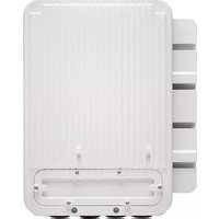
ACX500 - Router Juniper - Free user manual and instructions
Find the device manual for free ACX500 Juniper in PDF.


| Product Type | Router |
| Brand | Juniper |
| Model | ACX500 |
| Form Factor | 1U Rackmount |
| Dimensions (W x D x H) | 440 x 254 x 44 mm (17.3 x 10.0 x 1.7 in) |
| Weight | 6.0 kg (13.2 lb) |
| Power Input | AC: 100-240V, 50-60 Hz; DC: -48V |
| Power Consumption | 150W typical |
| Operating Temperature | 0 to 45°C (32 to 113°F) |
| Storage Temperature | -40 to 70°C (-40 to 158°F) |
| Relative Humidity | 5% to 90% non-condensing |
| Cooling | Internal fans, airflow front-to-back |
| Ports | 8 x GE (RJ-45), 4 x SFP+ (1/10 GbE) |
| Software | Junos OS |
| Routing Protocols | BGP, OSPF, IS-IS, MPLS, VPLS, L3VPN |
| Security | Firewall, ACL, MACsec (optional) |
| Maintenance | No user-serviceable parts; replaceable power supply and fans |
| Safety | Grounding required; comply with local electrical codes |
| Spare Parts | Spare power supply, fan tray optional |
| Accessories | Power cord, rack mount kit, console cable |
Frequently Asked Questions - ACX500 Juniper
User questions about ACX500 Juniper
0 question about this device. Answer the ones you know or ask your own.
Ask a new question about this device
Download the instructions for your Router in PDF format for free! Find your manual ACX500 - Juniper and take your electronic device back in hand. On this page are published all the documents necessary for the use of your device. ACX500 by Juniper.
USER MANUAL ACX500 Juniper
ACX500 Universal Access Router Hardware Guide
Modified: 2016-06-23
Juniper Networks, Inc.
1133 Innovation Way
Sunnyvale, California 94089
USA
408-745-2000
www.juniper.net
Copyright © 2016, Juniper Networks, Inc. All rights reserved.
Juniper Networks, Junos, Steel-Belted Radius, NetScreen, and ScreenOS are registered trademarks of Juniper Networks, Inc. in the United States and other countries. The Juniper Networks Logo, the Junos logo, and JunosE are trademarks of Juniper Networks, Inc. All other trademarks, service marks, registered trademarks, or registered service marks are the property of their respective owners.
Juniper Networks assumes no responsibility for any inaccuracies in this document. Juniper Networks reserves the right to change, modify, transfer, or otherwise revise this publication without notice.
ACX500 Universal Access Router Hardware Guide
Copyright © 2016, Juniper Networks, Inc.
All rights reserved.
The information in this document is current as of the date on the title page.
YEAR 2000 NOTICE
Juniper Networks hardware and software products are Year 2000 compliant. Junos OS has no known time-related limitations through the year 2038. However, the NTP application is known to have some difficulty in the year 2036.
END USER LICENSE AGREEMENT
The Juniper Networks product that is the subject of this technical documentation consists of (or is intended for use with) Juniper Networks software. Use of such software is subject to the terms and conditions of the End User License Agreement ("EULA") posted at http://www.juniper.net/support/eula.html. By downloading, installing or using such software, you agree to the terms and conditions of that EULA.
Table of Contents
About the Documentation ...... Documentation and Release Notes ...... Documentation Conventions ...... Documentation Feedback ...... Requesting Technical Support ...... Self-Help Online Tools and Resources ...... Opening a Case with JTAC ....
Part 1 Overview
Chapter1 System Overview .... 3 ACX500 Universal Access Router Overview .... ACX500 Router Models .... ACX500 Chassis Overview .... ACX500 Indoor Router Description .... ACX500 Outdoor Router Description .... ACX500 Outdoor Router with PoE Description .... ACX500 Routers Hardware and CLI Terminology Mapping .... ACX500 Indoor Routers Hardware and CLI Terminology Mapping .... 9 ACX500 Outdoor Routers Hardware and CLI Terminology Mapping .... 10 ACX500 Outdoor Routers with PoE Hardware and CLI Terminology Mapping .... Packet Flow on ACX Series Routers .... Protocols and Applications Supported by ACX Series Routers ....
Chapter 2 Chassis Components and Descriptions ..... Front Panel of an ACX500 Indoor Router ..... Front Panel of an ACX500 Outdoor Router ..... Front Panel of an ACX500 Outdoor Router with PoE ..... Alarm Contact Port on ACX500 Routers ..... LEDs on ACX500 Routers ..... System LED on the Front Panel ..... Gigabit Ethernet SFP and RJ-45 Port LEDs ..... Management Port LEDs on the Front Panel ..... GPS 1 PPS LED on the Front Panel ..... Uplink Ports on ACX500 Routers ..... Gigabit Ethernet RJ-45 Ports ..... Gigabit Ethernet SFP Ports ..... PoE Ports ..... Clocking Ports on ACX500 Routers ....
Chapter 3 Cooling System Components .....
Cooling System and Airflow in ACX500 Routers .....
Chapter 4 Power System Overview
ACX500 Power Overview
Part 2 Site Planning, Preparation, and Specifications
Chapter 5 Preparation Overview....53
Site Preparation Checklist for ACX500 Routers . . . . . . . . . . . . . . . . . . . . . . . . . .
Chassis Physical Specifications for ACX500 Routers .....
ACX500 Router Environmental Specifications ....
Rack Requirements for ACX500 Indoor Routers . . . . . . . . . . . . . . . . . . . . . . . .
Cabinet Requirements for ACX500 Indoor Routers
Wall Requirements for ACX500 Outdoor Routers . . . . . . . . . . . . . . . . . . . . . . . . .
Pole Requirements for ACX500 Outdoor Routers . . . . . . . . . . . . . . . . . . . . . .
Clearance Requirements for Airflow and Hardware Maintenance on ACX500 Routers....61
ACX500 Indoor Router Chassis Dimensions and Clearance Requirements
ACX500 Outdoor Router Chassis Dimensions and Clearance Requirements
ACX500 Outdoor Router with PoE Chassis Dimensions and Clearance Requirements
ACX500 Router Grounding Specifications ....
Grounding Points Specifications ..... Grounding Cable Lug Specifications ..... Grounding Cable Specifications ....
General Site Guidelines for ACX Series Routers . . . . . . . . . . . . . . . . . . . . . .
Chapter 6 Network Cable and Transceiver Planning . . . . . . . . . . . . . . . . . . . . . . . . . .
Understanding Fiber-Optic Cable Signal Loss, Attenuation, and Dispersion . . . . . 71
Signal Loss in Multimode and Single-Mode Fiber-Optic Cable . . . . . . . . . . . . . 71
Attenuation and Dispersion in Fiber-Optic Cable . . . . . . . . . . . . . . . . . . . . . . . . . .
Calculating Power Budget and Power Margin for Fiber-Optic Cables ..... 72
Calculating Power Budget for Fiber-Optic Cable . . . . . . . . . . . . . . . . . . . . .
Calculating Power Margin for Fiber-Optic Cable . . . . . . . . . . . . . . . . . . . . . . .
Chapter 7 Port Cable and Pinout Specifications ....
Alarm Contact Port Pinouts for ACX500 Routers . . . . . . . . . . . . . . . . . . . . . .
External Clocking Ports Specifications on ACX500 Routers . . . . . . . . . . . . . . . .
Management Port Connector Pinout Information for ACX500 Routers . . . . . . . . 77
Console Port Connector Pinout on ACX500 Routers
ToD RS-422 and 1 PPS RS-422 Port Connector Pinout on ACX500 Routers . . . . 78
USB Port Specifications for ACX500 Routers . . . . . . . . . . . . . . . . . . . . . . . . .
Chapter 8 Power Specifications 81
ACX500 AC Power Specifications
ACX500 Router AC Power Cord Specifications
ACX500 DC Power Specifications
Chapter 9 ACX500 Timing Server Specifications ....
Requirements and Specifications for Installing a GNSS Antenna . . . . . . . . . . . . . . 87
Requirements for Installing a GNSS Antenna . . . . . . . . . . . . . . . . . . . . . . .
ACX500 Router GNSS Antenna Signal Gain Requirements 88
General ACX500 GNSS Antenna Mounting and Installation Recommendations
Tools and Parts Required to Install the GNSS Antenna . . . . . . . . . . . . . . . .
Installing the ACX500 GNSS Antenna . . . . . . . . . . . . . . . . . . . . . . . . . . .
ACX500 GNSS Antenna Power Specification . . . . . . . . . . . . . . . . . . . . .
ACX500 GNSS Antenna Surge Protection . . . . . . . . . . . . . . . . . . . . . . . .
Antenna Installation Verification . . . . . . . . . . . . . . . . . . . . . . . . . . . . .
Requirements and Specifications for the Recommended GNSS Antenna ..... 95
Antenna Selection Guidelines
Recommended GNSS Antenna Specifications . . . . . . . . . . . . . . . . . . . . . . . . . .
Trimble Bullet 38dB GPS L1 Antenna Specifications . . . . . . . . . . . . . . . . . . . . . 95
Part 3 Initial Installation and Configuration
Chapter10 Installation Overview 101
Installing and Connecting an ACX500 Indoor Router Overview . . . . . . . . . . . . . . . 101
Installing and Connecting an ACX500 Outdoor Router Overview ..... 102
Chapter 11 Unpacking the ACX500 Router ....
Parts Inventory (Packing List) for ACX500 Routers . . . . . . . . . . . . . . . . . . . .
Unpacking the ACX500 Router
Chapter 12 Installing the ACX500 Router . . . . . . . . . . . . . . . . . . . . . . . . . . . . . . . . .
Installing the ACX500 Indoor Router in a Rack . . . . . . . . . . . . . . . . . . . . . . .
Mounting the ACX500 Outdoor Router on a Wall . . . . . . . . . . . . . . . . . . . . .
Mounting the ACX500 Outdoor Router on a Pole . . . . . . . . . . . . . . . . . . . . . .
Weatherproofing the ACX500 Outdoor Router . . . . . . . . . . . . . . . . . . . . . . . . .
Weatherproofing Overview . . . . . . . . . . . . . . . . . . . . . . . . . . . . . . . . . . . . . . . .
Accessing and Weatherproofing the Interface Ports ..... 12
Weatherproofing the Interface Ports—Gigabit Ethernet SFP ..... 123
Weatherproofing the Interface Ports—Gigabit Ethernet RJ-45 ..... 128
Accessing and Weatherproofing the Management Ports 133
Chapter 13 Connecting the ACX500 to Ground . . . . . . . . . . . . . . . . . . . . . . . . . . . . . .
Connecting the ACX500 Router to Earth Ground . . . . . . . . . . . . . . . . . . . . . . . .
Chapter 14 Providing Power to the ACX500 . . . . . . . . . . . . . . . . . . . . . . . . . . . . . . .
Connecting an AC Power Cord to the ACX500 Indoor Router . . . . . . . . . . . . . . . . . 1:
Connecting DC Power Cables to the ACX500 Indoor Router . . . . . . . . . . . . . . . . . 1
Connecting an AC Power Cord to the ACX500 Outdoor Router . . . . . . . . . . . . . . . . 1
Connecting a DC Power Cord to the ACX500 Outdoor Router . . . . . . . . . . . . . . .
Chapter 15 Connecting the ACX500 to External Devices . . . . . . . . . . . . . . . . . . . . . . .
Connecting ACX500 Routers to Management Devices . . . . . . . . . . . . . . . . . . . .
Connecting the Router to a Network for Out-of-Band Management ..... 152
Connecting the Router to a Management Console
Connecting the ACX500 Router to an External Alarm-Reporting Device . . . . . . 153
Connecting the ACX500 Router to External Clocking Devices . . . . . . . . . . . . . . . 15.
Connecting 1 PPS Timing Devices to the Router
Chapter 16 Configuring Junos OS on ACX500 Routers .....
Performing Initial Software Configuration for the ACX500 Router ..... 155
Part 4 Installing and Replacing Components
Chapter 17 Replacing Chassis Components .....
Replacing a Console Cable . . . . . . . . . . . . . . . . . . . . . . . . . . . . . . .
Removing a Console Cable . . . . . . . . . . . . . . . . . . . . . . . . . . . . . . .
Installing a Console Cable
Replacing a Management Ethernet Cable . . . . . . . . . . . . . . . . . . . . . . . . . . .
Removing a Management Ethernet Cable . . . . . . . . . . . . . . . . . . . . . . . . . . .
Installing a Management Ethernet Cable
Replacing a Fiber-Optic Cable . . . . . . . . . . . . . . . . . . . . . . . . . . . . .
Disconnecting a Fiber-Optic Cable . . . . . . . . . . . . . . . . . . . . . . . . . . .
Connecting a Fiber-Optic Cable . . . . . . . . . . . . . . . . . . . . . . . . . . . . . . .
Replacing an SFP Transceiver . . . . . . . . . . . . . . . . . . . . . . . . . . . . . . .
Removing an SFP Transceiver . . . . . . . . . . . . . . . . . . . . . . . . . . . . . .
Installing an SFP Transceiver . . . . . . . . . . . . . . . . . . . . . . . . . . . . . .
Part 5 Maintaining the Chassis and Components
Chapter 18 Maintaining Components ....
Routine Maintenance Procedures for the ACX500 Router . . . . . . . . . . . . . . . . . . . . . 16
Maintaining Cables That Connect to ACX500 Network Ports ..... 169
Maintaining the ACX500 Uplink Ports . . . . . . . . . . . . . . . . . . . . . . . . . . . .
Part 6 Troubleshooting Hardware
Chapter 19 Troubleshooting Components .....
Troubleshooting Resources for ACX500 Routers . . . . . . . . . . . . . . . . . . . . . . .
Command-Line Interface
Front Panel LEDs . . . . . . . . . . . . . . . . . . . . . . . . . . .
Understanding Alarm Types and Severity Classes on ACX Series Routers . . . . . . 176
Alarm Types
Alarm Severity Classes ....
Verifying Active Alarms
Monitoring System Log Messages . . . . . . . . . . . . . . . . . . . . . . . . . . . . . . . . .
Part 7 Contacting Customer Support and Returning the Chassis or Components
Chapter 20 Contacting Customer Support . . . . . . . . . . . . . . . . . . . . . . . . . . . . . . . . . . . . . . .
Contacting Customer Support . . . . . . . . . . . . . . . . . . . . . . . . . . . . . . . . . .
Chapter 21 Locating Component Serial Numbers . . . . . . . . . . . . . . . . . . . . . . . . . . . . . .
Displaying ACX500 Components and Serial Numbers . . . . . . . . . . . . . . . . . . .
ACX500 Chassis Serial Number Label
Chapter 22 Packing and Returning Components .....
Returning a Hardware Component to Juniper Networks, Inc. 18
Packing the ACX Series Router for Shipment . . . . . . . . . . . . . . . . . . . . . . . . . .
Guidelines for Packing Hardware Components for Shipment 187
Part 8 Safety and Compliance Information
Chapter 23 General Safety Guidelines and Warnings . . . . . . . . . . . . . . . . . . . . . . . . . .
Definition of Safety Warning Levels . . . . . . . . . . . . . . . . . . . . . . . . . . . . . . .
General Safety Guidelines for Juniper Networks Devices . . . . . . . . . . . . . . . . . . . . . . . . 1
General Safety Warnings for Juniper Networks Devices . . . . . . . . . . . . . . . . . .
Qualified Personnel Warning . . . . . . . . . . . . . . . . . . . . . . . . . . . . . . . . .
Restricted-Access Area Warning . . . . . . . . . . . . . . . . . . . . . . . . . . . . . .
Preventing Electrostatic Discharge Damage to an ACX500 Router . . . . . . . . . . 196
In Case of an Electrical Accident . . . . . . . . . . . . . . . . . . . . . . . . . . . . .
Chapter 24 Fire Safety Requirements....199
Fire Safety Requirements for Juniper Networks Devices . . . . . . . . . . . . . . . . . .
General Fire Safety Requirements . . . . . . . . . . . . . . . . . . . . . . . . . . . . .
Fire Suppression
Fire Suppression Equipment
Chapter 25 Installation Safety Guidelines and Warnings . . . . . . . . . . . . . . . . . . . . . . . . .
Installation Safety Warnings for Juniper Networks Devices 20
Intrabuilding Ports Warning
Installation Instructions Warning . . . . . . . . . . . . . . . . . . . . . . . . . . . . . . .
Rack-Mounting Requirements and Warnings ..... 2
Ramp Warning
ACX500 Chassis Lifting Guidelines
Chapter 26 Laser and LED Safety Guidelines and Warnings ..... 2
General Laser Safety Guidelines for Juniper Networks Devices 209
Laser Safety Warnings for Juniper Networks Devices . . . . . . . . . . . . . . . . . . . . .
Class 1 Laser Product Warning . . . . . . . . . . . . . . . . . . . . . . . . . . . . . . . .
Class 1 LED Product Warning . . . . . . . . . . . . . . . . . . . . . . . . . . . . . .
Laser Beam Warning
Radiation from Open Port Apertures Warning . . . . . . . . . . . . . . . . . . . . . . .
Chapter 27 Maintenance and Operational Safety Warnings 213
Maintenance and Operational Safety Warnings for Juniper Networks Devices . . 213
Battery Handling Warning
Jewelry Removal Warning
Lightning Activity Warning
Operating Temperature Warning
Product Disposal Warning
Chapter 28 Electrical Safety Guidelines and Warnings .....
ACX500 General Electrical Safety Guidelines .....
In Case of Electrical Accident
General Electrical Safety Guidelines . . . . . . . . . . . . . . . . . . . . . . . . . . . .
General Electrical Safety Warnings for Juniper Networks Devices ..... 220
Grounded Equipment Warning
Grounding Requirements and Warning . . . . . . . . . . . . . . . . . . . . . . . . . . . . .
Midplane Energy Hazard Warning
Multiple Power Supplies Disconnection Warning 22
Power Disconnection Warning
General Electrical Safety Guidelines and Electrical Codes for Juniper Networks
Devices
ACX500 AC Power Electrical Safety Guidelines and Warnings 224
ACX500 DC Power Electrical Safety Guidelines
DC Power Electrical Safety Warnings for Juniper Networks Devices . . . . . . . . . 226
DC Power Copper Conductors Warning
DC Power Disconnection Warning
DC Power Wiring Terminations Warning . . . . . . . . . . . . . . . . . . . . . . . . . .
Site Electrical Wiring Guidelines for Juniper Networks Devices 229
Distance Limitations for Signaling ....
Radio Frequency Interference ....
Electromagnetic Compatibility
Chapter 29 Agency Approvals and Compliance Statements 23
Agency Approvals for ACX500 Routers . . . . . . . . . . . . . . . . . . . . . . . . . . . .
Compliance Statements for NEBS for ACX500 Routers ..... 2
Compliance Statements for EMC Requirements for ACX500 Routers . . . . . . . 236
ACX500 Indoor Routers
Canada
European Community
Israel
Japan
United States
ACX500 Outdoor Routers
Canada
European Community
Japan
United States
Compliance Statements for Environmental Requirements for Juniper Networks
Devices 238
Compliance Statements for Acoustic Noise for ACX500 Routers ..... 238
List of Figures
Part 1 Overview
Chapter 1 System Overview....3
Figure 1: Front View of the ACX500 Indoor Routers—AC Powered . . . . . . . . . . . . .
Figure 2: Front View of the ACX500 Indoor Routers—DC Powered . . . . . . . . . . .
Figure 3: Rear View of the ACX500 Indoor Router . . . . . . . . . . . . . . . . . . .
Figure 4: Bottom View of the ACX500 Outdoor Router . . . . . . . . . . . . . . . . . .
Figure 5: Top View of the ACX500 Outdoor Router . . . . . . . . . . . . . . . . . . . . .
Figure 6: Bottom View of the ACX500 Outdoor Router with PoE . . . . . . . . . . . .
Figure 7: Top View of the ACX500 Outdoor Router with PoE . . . . . . . . . . . . . .
Figure 8: ACX500 Indoor Router Interface Port Mapping—DC and AC Chassis . . . 10
Figure 9: ACX500 Outdoor Router Interface Port Mapping . . . . . . . . . . . . . . . .
Figure 10: ACX500 Outdoor Router Interface Port Mapping . . . . . . . . . . . . . . . .
Figure 11: ACX Series Router Packet Forwarding and Data Flow . . . . . . . . . . . .
Figure 12: ACX Series Router Packet Handling . . . . . . . . . . . . . . . . . . . . . . . .
Chapter 2 Chassis Components and Descriptions .....
Figure 13: Front Panel of the ACX500 Indoor Router—AC Chassis .....
Figure 14: Front Panel of the ACX500 Indoor Router-DC Chassis . . . . . . . . . . . . . . 35
Figure 15: Front Panel of the ACX500 Outdoor Router . . . . . . . . . . . . . . . . . .
Figure 16: Front Panel of the ACX500 Outdoor Router—Management Ports . . . . 36
Figure 17: Front Panel of the ACX500 Outdoor Router—Interface Ports ..... 37
Figure 18: Front Panel of the ACX500 Outdoor Router with PoE . . . . . . . . . . . .
Figure 19: Front Panel of the ACX500 Outdoor Router with PoE—Management Ports 38
Figure 20: Front Panel of the ACX500 Outdoor Router with PoE—Interface Ports ....39
Figure 21: Sample Output Alarm-Reporting Device .....
Figure 22: Sample Input Alarm-Reporting Device . . . . . . . . . . . . . . . . . . . . . .
Chapter 3 Cooling System Components .....
Figure 23: Cooling System and Airflow in the ACX500 Indoor Router . . . . . . . . . . . 47
Figure 24: Cooling System in the ACX500 Outdoor Routers .....
Part 2 Site Planning, Preparation, and Specifications
Chapter 5 Preparation Overview....53
Figure 25: ACX500 Indoor Router Chassis Dimensions and Clearance Requirements
Figure 26: ACX500 Outdoor Router Chassis Dimensions and Clearance Requirements—Front View ....
Figure 27: ACX500 Outdoor Router Chassis Dimensions and Clearance Requirements—Top View
Figure 28: ACX500 Outdoor Router with PoE Chassis Dimensions and Clearance Requirements—Front View.
Figure 29: ACX500 Outdoor Router with PoE Chassis Dimensions and Clearance Requirements—Top View
Figure 30: Grounding Points on the ACX500 Indoor Routers .....
Figure 31: Grounding Points on the ACX500 Outdoor Router . . . . . . . . . . . . . . .
Figure 32: Grounding Cable Lug
Chapter 9 ACX500 Timing Server Specifications . . . . . . . . . . . . . . . . . . . . . . . . . . .
Figure 33: Antenna Clearance Requirement—Peripheral ..... 9
Figure 34: Antenna Clearance Requirement—Field of View
Figure 35: Standard GNSS Antenna Parts
Part 3 Initial Installation and Configuration
Chapter 12 Installing the ACX500 Router . . . . . . . . . . . . . . . . . . . . . . . . . . . . . . . .
Figure 36: Installing the Mounting Brackets to the Front of the ACX500 Router....110
Figure 37: Installing the Mounting Brackets to the Rear of the ACX500 Router....110
Figure 38: Installing the ACX500 Indoor Router in the Rack . . . . . . . . . . . . . . .
Figure 39: Wall-Mounting Kit
Figure 40: Installing the Wall-Mounting Kit . . . . . . . . . . . . . . . . . . . . . . . . . . .
Figure 41: Installing the ACX500 Outdoor Router onto the Wall-Mounting Kit . . . 116
Figure 42: Pole-Mounting Kit
Figure 43: Installing the ACX500 Outdoor Router onto the Pole-Mounting Kit . . 119
Figure 44: Securing the ACX500 Outdoor Router on the Pole . . . . . . . . . . . . . . . . . . . . . . . .
Figure 45: Interface Port and Cable Inlet Cover . . . . . . . . . . . . . . . . . . . . . . . . . . .
Figure 46: Removing the Weather Seal Cap . . . . . . . . . . . . . . . . . . . . . . . . .
Figure 47: Removing the ACX500 Outdoor Router Cable Connector Unit ..... 124
Figure 48: Installing a Transceiver on the ACX500 Outdoor Router ..... 125
Figure 49: Installing the ACX500 Outdoor Router Cable Seal on the Interface Cable 126
Figure 50: ACX500 Outdoor Router Cable Connector Unit . . . . . . . . . . . . . . . .
Figure 51: Installing the ACX500 Outdoor Router Connector Screw ..... 128
Figure 52: Removing the ACX500 Outdoor Router Weather Seal Cap ..... 129
Figure 53: Removing the Cable Connector Unit . . . . . . . . . . . . . . . . . . . . . . .
Figure 54: Cable Connector Unit
Figure 55: Installing the ACX500 Outdoor Router Cable Seal on the Interface Cable 132
Figure 56: Installing the ACX500 Outdoor Router Connector Screw ..... 132
Chapter 13 Connecting the ACX500 to Ground . . . . . . . . . . . . . . . . . . . . . . . . . . . . .
Figure 57: Grounding Point Location on the ACX500 Indoor Router ..... 136
Figure 58: Grounding Point Location on the ACX500 Outdoor Router ..... 136
Figure 59: Grounding Points on the ACX500 Indoor Router . . . . . . . . . . . . . . .
Chapter 14 Providing Power to the ACX500 . . . . . . . . . . . . . . . . . . . . . . . . . . . . . . . . .
Figure 60: Connecting AC Power to the Router . . . . . . . . . . . . . . . . . . . . . . . .
Figure 61: Connecting DC Power to the Router . . . . . . . . . . . . . . . . . . . . . . . . .
Figure 62: Power Terminal Location on the ACX500 Outdoor Router ..... 144
Figure 63: AC Power Cord Wires That Connect to the Power Source ..... 14
Figure 64: Connecting AC Power Plug to the Router . . . . . . . . . . . . . . . . . . . .
Figure 65: Power Terminal Location on the ACX500 Outdoor Router ..... 148
Figure 66: Connecting DC Power to the Router . . . . . . . . . . . . . . . . . . . . . . . .
Chapter 15 Connecting the ACX500 to External Devices . . . . . . . . . . . . . . . . . . . . . . .
Figure 67: Ethernet Cable Connector
Figure 68: Ethernet Port
Figure 69: Routing Engine Console Cable Connector .....
Figure 70: Console Connections
Part 4 Installing and Replacing Components
Chapter 17 Replacing Chassis Components .....
Figure 71: Ethernet Cable Connectors .....
Figure 72: Ethernet Cable Connectors
Figure 73: Connecting a Fiber-Optic Cable to an Optical Transceiver Installed in an ACX Series Router.
Figure 74: Removing Transceivers ....
Part 7 Contacting Customer Support and Returning the Chassis or Components
Chapter 21 Locating Component Serial Numbers .....
Figure 75: Serial Number ID Label . . . . . . . . . . . . . . . . . . . . . . . . . . . . . .
Figure 76: ACX500 Indoor Chassis Serial Number Label . . . . . . . . . . . . . . . . . . .
Figure 77: ACX500 Outdoor Chassis Serial Number Label ..... 1
Part 8 Safety and Compliance Information
Chapter 23 General Safety Guidelines and Warnings ....
Figure 78: ESD Point on ACX500 Indoor Router . . . . . . . . . . . . . . . . . . . . .
Figure 79: Placing a Component into an Electrostatic Bag . . . . . . . . . . . . . . . .
List of Tables
About the Documentation ....
Table 1: Notice Icons....xvi
Table 2: Text and Syntax Conventions
Part 1 Overview
Chapter 1 System Overview....3
Table 3: ACX500 Router Models .....
Table 4: ACX500 Router Differences
Table 5: CLI Equivalents of Terms Used in Documentation for ACX500 Indoor Routers 9
Table 6: CLI Equivalents of Terms Used in Documentation for ACX500 Outdoor Routers .....11
Table 7: CLI Equivalents of Terms Used in Documentation for ACX500 Outdoor Routers with PoE
Table 8: Protocols and Applications Supported by ACX Series Routers ..... 15
Chapter 2 Chassis Components and Descriptions ....
Table 9: Alarm Relay Contact Functions
Table 10: System LED on the Front Panel
Table 11: Ethernet Port LEDs
Table 12: Management LEDs
Table 13: GPS 1 PPS LED on the Front Panel
Table 14: RJ-45 Port Features
Table 15: Gigabit Ethernet SFP Port Features
Table 16: RJ-45 PoE Port Features
Chapter 4 Power System Overview
Table 17: Power Consumed by ACX500 Indoor Routers
Table 18: Power Consumed by ACX500 Outdoor Routers
Part 2 Site Planning, Preparation, and Specifications
Chapter 5 Preparation Overview....53
Table 19: Site Preparation Checklist .....
Table 20: Physical Specifications of the ACX500 Indoor Router Chassis ..... 55
Table 21: Physical Specifications of the ACX500 Outdoor Router Chassis ..... 55
Table 22: Physical Specifications of the ACX500 Outdoor Router with PoE Chassis .... 55
Table 23: Weight of the Mounting Kits
Table 24: Environmental Specifications
Table 25: Rack Requirements and Specifications for the ACX500 Indoor Router 58
Table 26: Cabinet Requirements and Specifications for the ACX500 Indoor Router 59
Chapter 6 Network Cable and Transceiver Planning . . . . . . . . . . . . . . . . . . . . . . . . . . . .
Table 27: Estimated Values for Factors Causing Link Loss . . . . . . . . . . . . . . . .
Chapter 7 Port Cable and Pinout Specifications ....
Table 28: Alarm Contact Connector Pinouts . . . . . . . . . . . . . . . . . . . . . . . . . .
Table 29: Management Port Connector Pinout Information . . . . . . . . . . . . . . . . .
Table 30: Connector Pinout for the Console Port . . . . . . . . . . . . . . . . . . . . . . . . . . . . . . . . . . . . . . . . . . . . . . . . . . . . . . . . . . . . . . . . . . . . . . . . . . . . . . . . . . . . . . . . . . . . . . . . . . . . Table 31: Connector Pinout for the TOD RS-422 and 1 PPS RS-422 Ports. . . . . . . 79
Chapter 8 Power Specifications 81
Table 32: AC Power Electrical Specifications .....
Table 33: AC Power Cord Specifications for the ACX500 Indoor Router ..... 82
Table 34: DC Power Electrical Specifications . . . . . . . . . . . . . . . . . . . . . .
Chapter 9 ACX500 Timing Server Specifications . . . . . . . . . . . . . . . . . . . . . . . . . . . .
Table 35: Antenna Mounting Requirements . . . . . . . . . . . . . . . . . . . . . . . . . . . .
Table 36: Standard Antenna Parts, Tools, and Other Required Items ..... 92
Table 37: Electrical Power Specifications of ACX500 GNSS Output Connector for Antenna Power
Table 38: Trimble Bullet 38dB GPS L1 Antenna Specifications . . . . . . . . . . . . . . . . .
Table 39: Antenna Cable Specification for Trimble Bullet 38dB GPS L1 Antenna
Part 3 Initial Installation and Configuration
Chapter 11 Unpacking the ACX500 Router . . . . . . . . . . . . . . . . . . . . . . . . . . . . . . .
Table 40: Parts List for an ACX500 Indoor Router . . . . . . . . . . . . . . . . . . .
Table 41: Parts List for an ACX500 Outdoor Router . . . . . . . . . . . . . . . . . .
Table 42: Parts List for the Wall-Mounting Kit . . . . . . . . . . . . . . . . . . . . . . . .
Table 43: Parts List for the Pole-Mounting Kit . . . . . . . . . . . . . . . . . . . . . . . .
Part 6 Troubleshooting Hardware
Chapter 19 Troubleshooting Components .....
Table 44: Alarm Terms
Table 45: Alarm Output Fields
About the Documentation
• Documentation and Release Notes on page xv
• Documentation Conventions on page xv
• Documentation Feedback on page xvii
- Requesting Technical Support on page xviii
Documentation and Release Notes
To obtain the most current version of all Juniper Networksal documentation, see the product documentation page on the Juniper Networks website at http://www.juniper.net/techpubs/.
If the information in the latest release notes differs from the information in the documentation, follow the product Release Notes.
Juniper Networks Books publishes books by Juniper Networks engineers and subject matter experts. These books go beyond the technical documentation to explore the nuances of network architecture, deployment, and administration. The current list can be viewed at http://www.juniper.net/books.
Documentation Conventions
Table 1 on page xvi defines notice icons used in this guide.
Table 1: Notice Icons
| DescriptionMeaningIcon | ||
| Indicates important features or instructions.Informational note | ||
| Indicates a situation that might result in loss of data or hardware damage.Caution | ||
| Alerts you to the risk of personal injury or death.Warning | ||
| Alerts you to the risk of personal injury from a laser.Laser warning | ||
| Indicates helpful information.Tip | ||
| Alerts you to a recommended use or implementation.Best practice |
Table 2 on page xvi defines the text and syntax conventions used in this guide.
Table 2: Text and Syntax Conventions
| ExamplesDescriptionConvention | ||
| Bold text like this | Represents text that you type. | To enter configuration mode, type theconfigure command:user@host>configure |
| Fixed-width text like this | Represents output that appears on theuser@host>show chassis alarms terminal screen.No alarms currently active | |
| Italic text like this | Introduces or emphasizes important new terms.Identifies guide names.Identifies RFC and Internet draft titles. | A policy term is a named structure that defines match conditions and actions.Junos OS CLI User GuideRFC 1997, BGP Communities Attribute |
| Italic text like this | Represents variables (options for whichConfigure the machine's domain name: you substitute a value) in commands or configuration statements.[edit]root@# set system domain-name domain-name | |
Table 2: Text and Syntax Conventions (continued)
| ExamplesDescriptionConvention | ||
| Text like this | Represents names of configuration statements, commands, files, and directories; configuration hierarchy levels; or labels on routing platform components. | To configure a stub area, include the stub statement at the [edit protocols ospf area area-id] hierarchy level.The console port is labeled CONSOLE. |
| < > (angle brackets) | Encloses optional keywords or variables. | stub; |
| | (pipe symbol) | Indicates a choice between the mutual exclusive keywords or variables on either side of the symbol. The set of choices (string1 | string2 | string3) often enclosed in parentheses for clarity. | |
| # (pound sign) | same line as the configuration statement to which it applies. | rsvp { # Required for dynamic MPLS only indicates a c |
| [ ] (square brackets) | Encloses a variable for which you can substitute one or more values. | community name members [ community-ids ] |
| Indention and braces ( { } ) | Identifies a level in the configuration hierarchy. | [edit]routing-options {static {route default {nexthop address;retain;}}} |
| ; (semicolon) | Identifies a leaf statement at a configuration hierarchy level. | |
| GUI Conventions | ||
| Bold text like this | Represents graphical user interface (GUI) In the Logical Interfaces box, select items you click or select. | All Interfaces.To cancel the configuration, click Cancel. |
| > (bold right angle bracket) | Separates levels in a hierarchy of men to the configuration editor hierarchy, selections. | select Protocols>Ospf. |
Documentation Feedback
We encourage you to provide feedback, comments, and suggestions so that we can improve the documentation. You can provide feedback by using either of the following methods:
- Online feedback rating system—On any page of the Juniper Networks TechLibrary site at http://www.juniper.net/techpubs/index.html, simply click the stars to rate the content, and use the pop-up form to provide us with information about your experience. Alternately, you can use the online feedback form at http://www.juniper.net/techpubs/feedback/.
- E-mail—Send your comments to techpubs-comments@juniper.net. Include the document or topic name, URL or page number, and software version (if applicable).
Requesting Technical Support
Technical product support is available through the Juniper Networks Technical Assistance Center (JTAC). If you are a customer with an active J-Care or Partner Support Service support contract, or are covered under warranty, and need post-sales technical support, you can access our tools and resources online or open a case with JTAC.
- JTAC policies—For a complete understanding of our JTAC procedures and policies, review the JTAC User Guide located at http://www.juniper.net/us/en/local/pdf/resource-guides/7100059-en.pdf.
- Product warranties—For product warranty information, visit http://www.juniper.net/support/warranty/.
- JTAC hours of operation—The JTAC centers have resources available 24 hours a day, 7 days a week, 365 days a year.
Self-Help Online Tools and Resources
For quick and easy problem resolution, Juniper Networks has designed an online self-service portal called the Customer Support Center (CSC) that provides you with the following features:
• Find CSC offerings: http://www.juniper.net/customers/support/
• Search for known bugs: http://www2.juniper.net/kb/
• Find product documentation: http://www.juniper.net/techpubs/
• Find solutions and answer questions using our Knowledge Base: http://kb.juniper.net/
- Download the latest versions of software and review release notes: http://www.juniper.net/customers/csc/software/
- Search technical bulletins for relevant hardware and software notifications: http://kb.juniper.net/InfoCenter/
- Join and participate in the Juniper Networks Community Forum: http://www.juniper.net/company/communities/
- Open a case online in the CSC Case Management tool: http://www.juniper.net/cm/
To verify service entitlement by product serial number, use our Serial Number Entitlement (SNE) Tool: https://tools.juniper.net/SerialNumberEntitlementSearch/
Opening a Case with JTAC
You can open a case with JTAC on the Web or by telephone.
- Use the Case Management tool in the CSC at http://www.juniper.net/cm/.
- Call 1-888-314-JTAC (1-888-314-5822 toll-free in the USA, Canada, and Mexico).
For international or direct-dial options in countries without toll-free numbers, see http://www.juniper.net/support/requesting-support.html.
PART 1
Overview
• System Overview on page 3
- Chassis Components and Descriptions on page 33
• Cooling System Components on page 47
• Power System Overview on page 49
CHAPTER 1
System Overview
• ACX500 Universal Access Router Overview on page 3
• ACX500 Router Models on page 4
• ACX500 Chassis Overview on page 5
• ACX500 Routers Hardware and CLI Terminology Mapping on page 9
- Packet Flow on ACX Series Routers on page 13
- Protocols and Applications Supported by ACX Series Routers on page 15
ACX500 Universal Access Router Overview
Juniper Networks ACX500 Universal Access Routers are principally designed to provide superior management for rapid provisioning to the access network. The ACX500 routers support rich Gigabit Ethernet capabilities for uplink, along with support Gigabit Ethernet interfaces in a compact form factor that is environmentally hardened and passively cooled. Seamless, end-to-end MPLS can be used to address legacy and emerging requirements to provide the foundation for a converged network that utilizes the same mobile backhaul infrastructure for business or residential services.
The routers have a built-in Routing Engine and one Packet Forwarding Engine. The Packet Forwarding Engine has one "pseudo" Flexible PIC Concentrator (FPC 0). Because there is no switching fabric, the single Packet Forwarding Engine takes care of packet forwarding.
- Routing Engine—Provides Layer 3 routing services and network management.
- Packet Forwarding Engine—Performs Layer 2 and Layer 3 packet switching, route lookups, and packet forwarding.
The Juniper Networks ACX Series Routers are powered by the Junos operating system (Junos OS), which supports extensive Layer 2 and Layer 3 features, IP and MPLS with traffic engineering, rich network management, fault management, service monitoring and Operation, Administration, and Maintenance (OAM) capabilities, and an open software development kit (SDK) system that enables providers to customize and integrate operations with their own management systems. For a list of related Junos OS documentation, see http://www.juniper.net/techpubs/software/junos/.
As part of the mobile backhaul, an ACX Series router at the cell site and an MX Series router at the aggregation layer provide comprehensive end-to-end Ethernet, MPLS, and OAM features with the one Junos OS running on both platforms.
The ACX500 routers can be installed indoors as well as outdoors:
- ACX500 Indoor—The compact ACX500 indoor routers are one rack unit (U; that is, 1.75 in. or 4.45 cm) tall. Several routers can be stacked in a single floor-to-ceiling rack for increased port density per unit of floor space. The chassis is a rigid sheet metal structure that houses all the other router components. The chassis of the ACX500 indoor router measures 1.75 in. (4.45 cm) high, 9.4 in. (24 cm) deep, and 17.5 in. (44.5 cm) wide. The outer edges of the mounting brackets extend the width to 19 in. (48 cm) (from the front-mounting brackets to the rear of the chassis). The chassis installs in standard 300-mm deep (or larger) enclosed cabinets, 19-in. equipment racks, or telco open-frame racks.
- ACX500 outdoor—The compact ACX500 outdoor routers are environmental hardened, and can be deployed in an outdoor environment, such as on walls and poles. The chassis of the ACX500 indoor router measures 1.75 in. (4.45 cm) high, 9.4 in. (24 cm) deep, and 17.5 in. (44.5 cm) wide. The chassis of the ACX500 outdoor router with the Power over Ethernet (PoE) unit measures 16 in. (40.64 cm) high, 4.7 in. (11.93 cm) deep, and 10 in. (25.4 cm) wide. You need to purchase the pole-mounting kit or the wall-mounting kit from Juniper Networks to mount the router in an outdoor environment.
Related
Documentation
ACX500 Chassis Overview on page 5.
- ACX500 Router Models on page 4
- ACX500 Routers Hardware and CLI Terminology Mapping on page 9
ACX500 Router Models
The ACX500 routers are available in different models. Table 3 on page 4 lists the various ACX500 router models available and provide a brief description of each base unit.
Table 3: ACX500 Router Models
| DescriptionModel NumberRouter | ||
| ACX500 indoor small-cell router with AC chassisACX500-ACACX500 indoor | ||
| ACX500 indoor small-cell router with DC chassisACX500-DC | ||
| ACX500 outdoor small-cell router with AC chassisACX500-O-AC | ||
| ACX500-O-DC | ACX500 outdoor small-cell router with DC chassis | |
| ACX500 outdoor with PoE | ACX500-O-POE-AC | ACX500 outdoor small-cell router with AC chassis and PoE |
| ACX500-O-POE-DC | ACX500 outdoor small-cell router with DC chassis and PoE |
Table 4 on page 5 lists the differences between the three ACX500 routers.
Table 4: ACX500 Router Differences
| Specifications Outdoor with | ACX500 Router Models | ||
| PoEOutdoorIndoor | |||
| OutdoorOutdoorIndoorDeployment | |||
| Number of ports | 6610 (total number of ports) | ||
| 6 (usable at any point) | |||
| PoE support | NoYes | Yes | |
| 3 ports | 3 ports | ||
| Maximum power consumption | 55 W65 W without PoE | 55 W without PoE | |
| 145 W with maximum PoE load(80 W of PoE) | 135 W with maximum PoE load(80 W of PoE) | ||
| Chassis dimension (height x depth x width; chassis in installed position) | 1.75 x 9.4 x 17.5 in. | 12.3 x 4.3 x 10 in. | 16 x 4.7 x 10 in. |
| Weight | 8.6 lb | 18.2 lb (AC chassis) | 18.7 lb (AC chassis) |
| 17.5 lb (DC chassis) | 18.6 lb (DC chassis) | ||
Related Documentation
ACX500 Chassis Overview on page 5
- Chassis Physical Specifications for ACX500 Routers on page 54
• ACX500 Universal Access Router Overview on page 3
ACX500 Chassis Overview
• ACX500 Indoor Router Description on page 5
• ACX500 Outdoor Router Description on page 6
- ACX500 Outdoor Router with PoE Description on page 8
ACX500 Indoor Router Description
The ACX500 indoor routers contain a total of 10 ports that support 1-Gbps speed, eight of which are labeled COMBO. At any point of time, you can use a maximum of six ports.
The ports labeled COMBO (combination ports) consist of four Gigabit Ethernet ports that support RJ-45 connectors and four Gigabit Ethernet ports that support small form-factor pluggable (SFP) transceivers. Out of the four RJ-45 ports, three ports support Power over Ethernet (PoE+ and PoE++).
The two ports that are not part of the COMBO ports are Gigabit Ethernet SFP ports.
On the ACX500, the six ports that you can use at any point of time can be two Gigabit Ethernet SFP ports (non-combination) and four ports from the COMBO ports.

NOTE: You can mix and match the four RJ-45 and SFP COMBO ports as long as the port numbers are unique.
For example, from the COMBO ports, you can use the 0/1/0 SFP port along with the 0/1/1 PoE+ RJ-45 port, but not the 0/1/0 PoE++ RJ-45 port, as the port numbers of the SFP and the RJ-45 ports are same (0/1/0).
Figure 1 on page 6 and Figure 2 on page 6 shows the front views of the AC-powered and the DC-powered ACX500 indoor routers.
Figure 1: Front View of the ACX500 Indoor Routers—AC Powered

natural_image
Line drawing of a network switch device with ports and connectors (no text or symbols)Figure 2: Front View of the ACX500 Indoor Routers—DC Powered

natural_image
Line drawing of a network switch device with ports and connectors (no text or symbols)Figure 3 on page 6 shows the rear view of the AC-powered and the DC-powered ACX500 indoor routers.
Figure 3: Rear View of the ACX500 Indoor Router

natural_image
Pure electrical circuit lines without any symbols
NOTE: The top view and bottom view of an AC-powered ACX500 router are respectively the same as those of a DC-powered router. The only component that appears different is the power inlet for the two routers.
ACX500 Outdoor Router Description
The ACX500 outdoor routers contain three Gigabit Ethernet ports that support SFP transceivers and three Gigabit Ethernet ports that support RJ-45 connectors. The ACX500
outdoor routers install on a pole or a wall, with the chassis installed in a vertical orientation with the cables pointing downward and the eye bolt for hoisting the router pointing upward.
Figure 4 on page 7 and Figure 5 on page 7 show the ACX500 outdoor router from bottom and top.
Figure 4: Bottom View of the ACX500 Outdoor Router

| Interface port chamber with weather seal cover | 3-1- Management port chamber with weather seal cover |
| 2-Cable connector ports with weather seal cap | 4-Power port with weather seal cap |
Figure 5: Top View of the ACX500 Outdoor Router
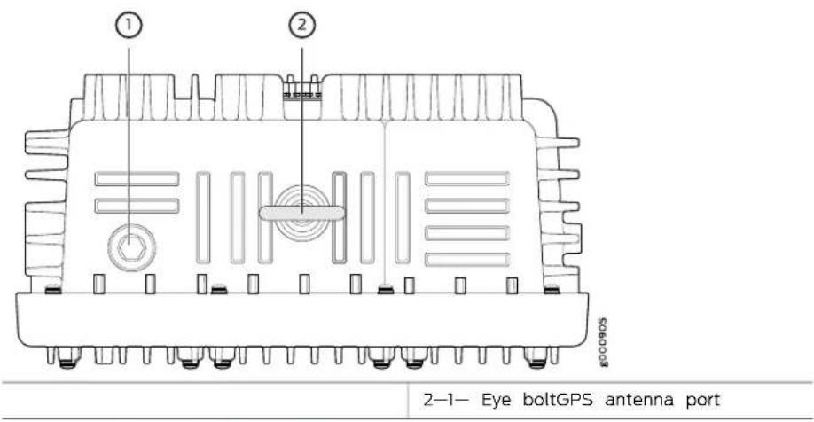

NOTE: The top view and bottom view of an AC-powered ACX500 router are respectively the same as those of a DC-powered router. The only component that appears different is the power inlet for the two routers.
ACX500 Outdoor Router with PoE Description
The ACX500 outdoor routers with Power over Ethernet (PoE) contain three Gigabit Ethernet RJ-45 ports that support PoE+ and three Gigabit Ethernet SFP ports. Out of the three RJ-45 ports, the port labeled 0/1/0 supports PoE++, and the ports labeled 0/1/1 and 0/1/2 support PoE+ with a maximum system PoE power limit of 80 W. The ACX500 outdoor routers with PoE install on a pole or a wall, with the chassis installed in a vertical orientation with the cables pointing downward and the eye bolt for hoisting the router pointing upward.
Figure 6 on page 8 and Figure 7 on page 8 show the ACX500 outdoor router with PoE from bottom and top.
Figure 6: Bottom View of the ACX500 Outdoor Router with PoE

| Interface port chamber with weather seal cover | 3-1- Management port chamber with weather seal cover |
| 2-Cable connector ports with weather seal cap | 4-Power port with weather seal cap |
Figure 7: Top View of the ACX500 Outdoor Router with PoE
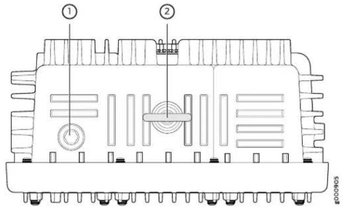
2-1- Eye boltGPS antenna port

NOTE: The top view and bottom view of an AC-powered ACX500 router are respectively the same as those of a DC-powered router. The only component that appears different is the power inlet for the two routers.
Related Documentation
ACX500 Router Models on page 4.
- ACX500 Routers Hardware and CLI Terminology Mapping on page 9
•Front Panel of an ACX500 Indoor Router on page 33
ACX500 Routers Hardware and CLI Terminology Mapping
- ACX500 Indoor Routers Hardware and CLI Terminology Mapping on page 9
- ACX500 Outdoor Routers Hardware and CLI Terminology Mapping on page 10
- ACX500 Outdoor Routers with PoE Hardware and CLI Terminology Mapping on page 12
ACX500 Indoor Routers Hardware and CLI Terminology Mapping
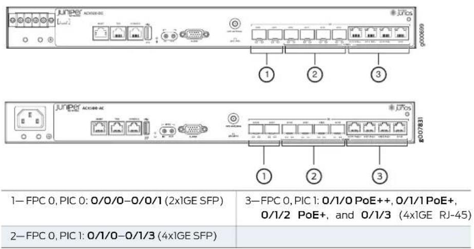
Table 5 on page 9 describes the hardware terms used in ACX500 indoor router documentation and the corresponding terms used in the Junos OS CLI. Figure 8 on page 10 shows the port locations of the interfaces.
Table 5: CLI Equivalents of Terms Used in Documentation for ACX500 Indoor Routers
| Hardware Item (as Displayed in the CLI) | Description (as Displayed in the CLI) | Value (as Displayed in the CLI) | Additional InformationItem | |
| Router chassis-ACX500Chassis Physical Specifications for ACX500 Routers" on page 54 | ||||
| FPC (n) | Abbreviated name of the Value of n is Flexible PIC Concentrator always 0. (FPC) | The router does not have Interface Naming Conventions actual FPCs. In this case, Used in the Junos OS FPC refers to the router Operational Commands itself. | ||
| PIC (n) | Abbreviated name of the n is a value in the Physical Interface Card range of 0–1. (PIC) | The router does not have Interface Naming Conventions actual PIC devices; see Used in the Junos OS entries for PIC 0 through Operational Commands PIC 1 for the equivalent item on the router. | ||
| PIC 02x 1GE (SFP) | Built-in uplink ports on the ACX500 Universal Access front panel of the router Router Overview" on page 3 | |||
| (COMBO PIC):4x 1GE (RJ-45 with PoE+ support)4x 1GE (SFP) | PIC 1One of the following uplink ports on the front panel of the router | "ACX500 Universal Access Router Overview" on page 3 | ||
| Xcvr (n) | Abbreviated name of the transceiver | equivalent to the number of the port in which the transceiver is installed. | Optical transceiversn is a "value" Routers" on page 43 | |
| supply (n) | Built-in power supplyPower always 0. | DC power supplyValue of ACIS500 Power Overview" on page 49 | ||
| Fan | NOTE: ACX500 routers are fanless. | Fan-Fan | "Cooling System and Airflow ACX500 Routers" on page 47 | |
Figure 8: ACX500 Indoor Router Interface Port Mapping—DC and AC Chassis
ACX500 Outdoor Routers Hardware and CLI Terminology Mapping
Table 6 on page 11 describes the hardware terms used in ACX500 outdoor router documentation and the corresponding terms used in the Junos OS CLI. Figure 9 on page 12 shows the port locations of the interfaces.
Table 6: CLI Equivalents of Terms Used in Documentation for ACX500 Outdoor Routers
| Hardware Item (as Displayed in the CLI) | Description (as Displayed in the CLI) | Value (as Displayed in the CLI) | Additional InformationItem | |
| Router chassis-ACX500Chassis Physical Specifications for ACX500 Routers" on page 54 | ||||
| FPC (n) | Abbreviated name of the Flexible PIC Concentrator (FPC) | Value of n is always 0. | The router does not have actual FPCs. In this case, FPC refers to the router itself. | Interface Naming Conventions Used in the Junos OS Operational Commands |
| PIC (n) | Abbreviated name of the Physical Interface Card (PIC) | n is a value in range of 0-1. | The router does not have actual PIC devices; see entries for PIC 0 through PIC 1 for the equivalent item on the router. | Interface Naming Conventions Used in the Junos OS Operational Commands |
| PIC 03x 1GE (SFP) | Built-in uplink ports on the "ACX500 Universal Access front panel of the router | Router Overview" on page 3 | ||
| PIC 13x 1GE (RJ-45) | Built-in uplink ports on the "ACX500 Universal Access front panel of the router | Router Overview" on page 3 | ||
| Xcvr (n) | Abbreviated name of the transceiver | equivalent to the number of the port in which the transceiver is installed. | Optical transceiversn is a valueink Ports on ACX500 Routers" on page 43 | |
| Power supply (n) | Built-in power supply | Value of n is always power supply 0. | "ACX500 Power Overview" on page 49 | |
| Fan | NOTE: ACX500 routers are fanless. | -Fan | Fan | "Cooling System and Airflow in ACX500 Routers" on page 47 |
Figure 9: ACX500 Outdoor Router Interface Port Mapping

ACX500 Outdoor Routers with PoE Hardware and CLI Terminology Mapping
Table 7 on page 12 describes the hardware terms used in ACX500 outdoor router with PoE documentation and the corresponding terms used in the Junos OS CLI. Figure 10 on page 13 shows the port locations of the interfaces.
Table 7: CLI Equivalents of Terms Used in Documentation for ACX500 Outdoor Routers with PoE
| Hardware Item (as Displayed in the CLI) | Description (as Displayed in the CLI) | Value (as Displayed in the CLI) | Additional InformationItem |
Router chassis-ACX500Chassis Physical Specifications for ACX500 Routers" on page 54
| FPC (n) | Abbreviated name of the Flexible PIC Concentrator (FPC) | Value of n is always 0. | The router does not have actual FPCs. In this case, Used in the Junos OS Operational FPC refers to the router Commands itself. | Interface Naming Conventions |
| PIC (n) | Abbreviated name of the Physical Interface Card (PIC) | n is a value in range of 0–1. | The router does not have actual PIC devices; see entries for PIC 0 through Commands PIC 1 for the equivalent item on the router. | Interface Naming Conventions Used in the Junos OS Operational |
| PIC 03x 1GE (SFP) Built-in uplink ports on the“ACX500 Universal Access front panel of the router Router Overview” on page 3 | |
| support) | PIC 13x 1GE (RJ-45 Build-in-PoEplink ports on the“ACX500 Universal Access front panel of the router Router Overview” on page 3 |
Table 7: CLI Equivalents of Terms Used in Documentation for ACX500 Outdoor Routers with PoE (continued)
| Hardware Item (as Displayed In the CLI) | Description (as Displayed In the CLI) | Value (as Displayed in the CLI) | Additional InformationItem | |
| Xcvr (n) | Abbreviated name of the transceiver | equivalent to the number of the port in which the transceiver is installed. | Optical transceiversn is a valuek Ports on ACX500 Routers" on page 43 | |
| supply (n) | Built-in power supplyPower 0. | DC power supplyValue of nAOS always Power Overview" on page 49 | ||
| Fan | NOTE: ACX500 routers are fanless. | Fan-Fan | "Cooling System and Airflow ACX500 Routers" on page 47 | |
Figure 10: ACX500 Outdoor Router Interface Port Mapping

| GPS LED | 3—FPC 0, PIC 1: 0/1/0-0/1/2 (3x1GE RJ-45 with PoE+ support) |
| 2—FPC 0, PIC 0: 0/0/0-0/0/2 (3x1GE SFP) |
Related Documentation
ACX500 Universal Access Router Overview on page 3
• ACX500 Router Models on page 4
Packet Flow on ACX Series Routers
The class-of-service (CoS) architecture for ACX Series routers is in concept similar to that for MX Series routers. The general architecture for ACX Series routers is shown in Figure 11 on page 14.
Figure 11: ACX Series Router Packet Forwarding and Data Flow

flowchart
graph LR
    A["Incoming packet"] --> B["Ingress classification\nIn order of decreasing precedence:\nMF classification (DFW)\nFixed classification\nBA classification"]
    B --> C["Buffering"]
    C --> D["Queuing"]
    D --> E["Scheduling"]
    E --> F["Egress rewrite"]
    F --> G["Outgoing packet"]
Based on the model, ACX Series routers contain a built-in Routing Engine and Packet Forwarding Engine and can contain both T1/E1 and Gigabit Ethernet Ports.
The Packet Forwarding Engine has one or two “pseudo” Flexible PIC Concentrators. Because there is no switching fabric, the single Packet Forwarding Engine takes care of both ingress and egress packet forwarding.
Fixed classification places all packets in the same forwarding class, or the usual multifield (MF) or behavior aggregate (BA) classifications can be used to treat packets differently. BA classification with firewall filters can be used for classification based on IP precedence, DSCP, IEEE, or other bits in the frame or packet header.
However, the ACX Series routers can also employ multiple BA classifiers on the same physical interface. The physical interfaces do not have to employ the same type of BA classifier. For example, a single physical interface can use classifiers based on IP precedence as well as IEEE 802.1p. If the CoS bits of interest are on the inner VLAN tag of a dual-tagged VLAN interface, the classifier can examine either the inner or outer bits. (By default, the classification is done based on the outer VLAN tag.)
Eight queues per egress port support scheduling using the weighted deficit round-robin (WDRR) mechanism, a form of round-robin queue servicing. The supported priority levels are strict-high and default (low). The ACX Series router architecture supports both weighted random early detect (WRED) and weighted tail drop (WTD).
All CoS features are supported at line rate.
The packet pipeline through an ACX Series router is shown in Figure 12 on page 15. Note that the rate limiting is done with an integrated architecture along with all other CoS functions. Scheduling and shaping are supported on the output side.
Figure 12: ACX Series Router Packet Handling

flowchart
graph TD
    A["BA and fixed classification\nForwarding class and packet loss priority"] --> B["MF classification\nPolicing can overwrite forwarding class and packet loss priority"]
    B --> C["Rate limiting"]
    C --> D["Scheduling and shaping\nForwarding class → Qn\nQn + packet loss priority → WRED"]
    D --> E["Forwarding class and packet loss priority determine rewrite value"]
    E --> F["Scheduling and shaping"]
Related Documentation
ACX500 Routers Hardware and CLI Terminology Mapping on page 9.
- ACX Series Universal Access Router Configuration Guide
Protocols and Applications Supported by ACX Series Routers
Table 8 on page 15 contains the first Junos OS Release support for protocols and applications on ACX Series routers. A dash indicates that the protocol or application is not supported.

NOTE:
- The [edit logical-systems logical-system-name] hierarchy level is not supported on ACX Series routers.
- TheACXSeriesroutersdoes not supportper-familymaximum transmission unit (MTU) configuration. The MTU applied to family inet gets applied to other families as well, even though it can be configured though CLI and visible in show Interface extensive output. The only way to use higher MTU for a family is to manipulate the MTU, apply at interface or family inet levels, and let it calculate for each family automatically. For more information, see the Knowledge Base (KB) article KB28179 at:
https://kb.juniper.net/InfoCenter/index?page=content&id=KB28179.
Table 8: Protocols and Applications Supported by ACX Series Routers
| Protocol or Application | ACX1000 | ACX1100 | ACX2000 | ACX2100 | ACX4000 | ACX5048 | ACX5096 | ACX500 |
Interface and Encapsulation Types
Table 8: Protocols and Applications Supported by ACX Series Routers (continued)
| Protocol or Application | ACX1000 | ACX1100 | ACX2000 | ACX2100 | ACX4000 | ACX5048 | ACX5096 | ACX500 |
| 10G | 12.2R212.212D3X512Ether-15.1X54 | 12.3X54-D20(Indoor) | ||||||
| -D10 | -D20 | -D20 | 12.3X54-D25(Outdoor) | |||||
| ----EthernetInterfaces-40G-D20 | -15.1X54 | |||||||
| ----12.2R212.2-12.2ATM inte | ||||||||
| ----12.2R212.2-12.2EI interfaces | ||||||||
| ----12.2R212.2-12.2TI interfaces | ||||||||
| Circuiternulation interfaces(SAToP, CESoP) | 12.2 | - | 12.2 | 12.2R2-D10 | ----12.3x51 | |||
| ----SONET/SDH interfaces-D10(requiresa MIC) | ----12.3x51 | |||||||
| Layer 3 | ||||||||
| 12.2R212.212D3X512Stats-D10 | 15.1X54es-D20 | 15.1X54-D20 | 12.3X54-D20(Indoor) | |||||
| 12.3X54-D25(Outdoor) | ||||||||
| 12.2R212.212D3X512OSPI-D10 | 15.1X54-D20 | 15.1X54-D20 | 12.3X54-D20(Indoor) | |||||
| 12.3X54-D25(Outdoor) | ||||||||
| 12.2R212.212D3X512IS-IS-D10 | 15.1X54-D20 | 15.1X54-D20 | 12.3X54-D20(Indoor) | |||||
| 12.3X54-D25(Outdoor) | ||||||||
Table 8: Protocols and Applications Supported by ACX Series Routers (continued)
| Protocol or Application | ACX1000 | ACX1100 | ACX2000 | ACX2100 | ACX4000 | ACX5048 | ACX5096 | ACX500 |
| 12.2R212.212ZBX512BGP15.1X54-D10 | 15.1X54-D20 | 12.3X54-D20(Indoor) | ||||||
| 12.3X54-D25(Outdoor) | ||||||||
| Protocol (ICMP) | 12.2R212.212ZBX512InterX5Control5Message-D10 | 12.3X54-D20(Indoor) | ||||||
| 12.3X54-D25(Outdoor) | ||||||||
| Protocol (ARP) | 12.2R212.212ZBX512AddressX5ResolutionX54-D10 | 12.3X54-D20(Indoor) | ||||||
| 12.3X54-D25(Outdoor) | ||||||||
| Detection (BFD) protocol | 12.2R212.212ZBX512BidirectionalF0/AX5ing-D10 | 12.3X54-D20(Indoor) | ||||||
| 12.3X54-D25(Outdoor) | ||||||||
| Configuration Protocol(DHCP) | 12.2R212.212ZBX512Dynab1X5Host-D10 | 15.1X54-D20 | 12.3X54-D20(Indoor) | |||||
| 12.3X54-D25(Outdoor) | ||||||||
| (OSPF, IS-IS) | 12.2R212.212ZBX512IP fastX5route15(FR54)-D10 | 12.3X54-D20(Indoor) | ||||||
| 12.3X54-D25(Outdoor) | ||||||||
| (MTU) 1518 | 12.2R212.212ZBX512Max15UX54trans153X54unit-D10 | 12.3X54-D20(Indoor) | ||||||
| 12.3X54-D25(Outdoor) | ||||||||
| 12.3R112.3R112.3R512.3R115.1X54- D10 | VPNS1X54-D20 | 12.3X54-D20(Indoor) | ||||||
| 12.3X54-D25(Outdoor) | ||||||||
| 12.2R212.212.2R3X512RSV15.1X54-D10 | 15.1X54-D20 | 12.3X54-D20(Indoor) | ||||||
| 12.3X54-D25(Outdoor) | ||||||||
| 12.2R212.212.2R3X512LDP15.1xTargetD10 | and 5 direct-D20 | 12.3X54-D20(Indoor) | ||||||
| 12.3X54-D25(Outdoor) | ||||||||
| MPLS, VPLS, VPNs | ||||||||
| (LSP) | 12.2R212.212.2R3X512Stat15.1x54-sw15.1X54path-D10 | -D20 | -D20 | 12.3X54-D20(Indoor) | ||||
| 12.3X54-D25(Outdoor) | ||||||||
| 12.2R212.212.2R3X512FRR15.1X54-D10 | -D20 | -D20 | 12.3X54-D20(Indoor) | |||||
| 12.3X54-D25(Outdoor) | ||||||||
| 12.2R212.212.2R3X512Traffic15.1xEngine15gX54-D10 | -D20 | -D20 | 12.3X54-D20(Indoor) | |||||
| 12.3X54-D25(Outdoor) | ||||||||
| 12.2R212.212D3X512E-LINE1X54-D10 | 15.1X54-D20 | 12.3X54-D20(Indoor)12.3X54-D25(Outdoor) | ||||||
| Edge to Edge (PWE3[signaled]) | 12.2R212.2-12.2R5audowife1X54ulation-D10 | -15.1X54 | ||||||
| 12.2R212.212D3X512Stat15.1X54-Ethernet15.1X54-D10 | 12.3X54-D20(Indoor)12.3X54-D25(Outdoor) | |||||||
| 12.2R212.212D3X512Layer15.1X54-Ericuits15.1X54-D10 | 12.3X54-D20(Indoor)12.3X54-D25(Outdoor) | |||||||
| on active and standby pseudowires | 12.2R212.212D3X512IEE8521X54-CC15.1X54-D10 | 12.3X54-D20(Indoor)12.3X54-D25(Outdoor) | ||||||
| ----VPLS15.1X54-D20 | -15.1X54 | |||||||
| Ethernet Layer 2(EFM 802.3ah) | 12.2R212.212D3X512Ethermax54-D10 | the15.1X54-D20 | 12.3X54-D20(Indoor)12.3X54-D25(Outdoor) | |||||
| management (CFM) | 12.2R212.212F8X51280216X54connectivity54fault-D10 | 12.3X54-D20(Indoor) | ||||||
| -D20 | -D20 | |||||||
| 12.3X54-D25(Outdoor) | ||||||||
| type, length, and value(TLV) | 12.2R212.212F8X512IEE8021X64interindexstatus-D10 | 12.3X54-D20(Indoor) | ||||||
| -D20 | -D20 | |||||||
| 12.3X54-D25(Outdoor) | ||||||||
| QoS | ||||||||
| control lists-ACLs)-familyinet | 12.2R212.212F8X512FirewallX54ters15ax54s-D10 | 12.3X54-D20(Indoor) | ||||||
| -D20 | -D20 | |||||||
| 12.3X54-D25(Outdoor) | ||||||||
| match conditions for MPLStraffic | 12.2R212.212F8X512StandardFirewall15x54er-D10 | 12.3X54-D20(Indoor) | ||||||
| -D20 | -D20 | |||||||
| 12.3X54-D25(Outdoor) | ||||||||
| ccc/any | 12.2R212.212F8X512FirewallX54ters15ax54-D10 | 12.3X54-D20(Indoor) | ||||||
| -D20 | -D20 | |||||||
| 12.3X54-D25(Outdoor) | ||||||||
| interface | 12.2R212.212F8X512PolicyingX54log15ax54-D10 | 12.3X54-D20(Indoor) | ||||||
| -D20 | -D20 | |||||||
| 12.3X54-D25(Outdoor) | ||||||||
| Interface | 12.2R212.212Z8X512Polidox-Per phylx54-D10 -D20 -D20 | 12.3X54-D20(Indoor)12.3X54-D25(Outdoor) | ||||||
| 12.2R212.212Z8X512Polidox-Per fatilyx54-D10 -D20 -D20 | 12.3X54-D20(Indoor)12.3X54-D25(Outdoor) | |||||||
| blind) | 12.2R212.212Z8X512TrCMIX54or aVAX54color12.3X54-D10 -D20 -D20 | 12.3X54-D20(Indoor)12.3X54-D25(Outdoor) | ||||||
| blind) | 12.2R212.212Z8X512SrCMIX54or aVAX54color12.3X54-D10 -D20 -D20 | 12.3X54-D20(Indoor)12.3X54-D25(Outdoor) | ||||||
| 12.2R212.212Z8X512Host5px54ection15.1X54-D10 -D20 -D20 | 12.3X54-D20(Indoor)12.3X54-D25(Outdoor) | |||||||
| 12.2R212.212Z8X512Eight5px54es pE1.1pErt-D10 -D20 -D20 | 12.3X54-D20(Indoor)12.3X54-D25(Outdoor) | |||||||
| 12.2R212.212Z8X512Priorlyx54euling15.1X54-D10 -D20 -D20 | 12.3X54-D20(Indoor)12.3X54-D25(Outdoor) | |||||||
| 12.2R212.212ZBX512Rate5dx54ol-D10 | 15.1X54-D20 | 12.3X54-D20(Indoor) | ||||||
| 12.3X54-D25(Outdoor) | ||||||||
| different priorities | 12.2R212.212ZBX512Schedux54 with 15x54-D10 | 12.3X54-D20(Indoor) | ||||||
| 12.3X54-D25(Outdoor) | ||||||||
| 12.2R212.212ZBX512Low-5ax54y quix5(LQ)-D10 | 12.3X54-D20(Indoor) | |||||||
| 12.3X54-D25(Outdoor) | ||||||||
| detection (WRED) drop profile (DP) | 12.2R212.212ZBX512Weight54randomlyD10 | 12.3X54-D20(Indoor) | ||||||
| 12.3X54-D25(Outdoor) | ||||||||
| 12.2R212.212ZBX512Class50x5ion-D5OR54-D10 | 12.3X54-D20(Indoor) | |||||||
| 12.3X54-D25(Outdoor) | ||||||||
| 12.2R212.212ZBX512Class50x5ion-MB1X55EXP-D10 | 12.3X54-D20(Indoor) | |||||||
| 12.3X54-D25(Outdoor) | ||||||||
| 12.2R212.212ZBX512Class50x5ion-IEEEX542.1p-D10 | 12.3X54-D20(Indoor) | |||||||
| 12.3X54-D25(Outdoor) | ||||||||
| 12.2R212.212D3X512RewHAX57SCP- D10 | 15.1X54-D20 | 12.3X54-D20(Indoor) | ||||||
| 12.3X54-D25(Outdoor) | ||||||||
| 12.2R212.212D3X512RewHAX54PLS- D10 | EXRX54-D20 | 12.3X54-D20(Indoor) | ||||||
| 12.3X54-D25(Outdoor) | ||||||||
| 12.2R212.212D3X512RewHAX5402.1p- D10 | 15.1X54-D20 | 12.3X54-D20(Indoor) | ||||||
| 12.3X54-D25(Outdoor) | ||||||||
| different values | 12.2R212.212D3X512RewHAX54PLS- D10 | intDX54- D20 | to2.3X54-D20(Indoor) | |||||
| 12.3X54-D25(Outdoor) | ||||||||
| Timing | ||||||||
| 1588-2008-backup clock | 12.2R212.212.2R212.2Timing-1588-v2,--12.3x51-D10 | 12.3X54-D20(Indoor) | ||||||
| 12.3X54-D25(Outdoor) | ||||||||
| 12.2R212.212.2R212.2Synchronous EtherIn23x51-D10 | 12.3X54-D20(Indoor) | |||||||
| 12.3X54-D25(Outdoor) | ||||||||
| supply (BITS) | 12.2R212.212.2R212.2Building-integrated Building -D10 | 12.3X54-D20(Indoor) | ||||||
| 12.3X54-D25(Outdoor) | ||||||||
| 12.2R212.212.2R212.2Clock synchronization -D10 | 12.3X54-D20(Indoor) | |||||||
| 12.3X54-D25(Outdoor) | ||||||||
| 1588 masters) | Redundant clock (multiple- | |||||||
| Transparent clock | ---- | 15.1X54-D20 | -D20 | -15.1X54 | ||||
| Grand Master Clock | 12.3X54-D20(Indoor) | |||||||
| 12.3X54-D25(Outdoor) | ||||||||
| OAM, Troubleshooting, Manageability, Lawful Intercept(NTP) | 12.2R212.212.2R212Network Time -D10 | -D20 | -D20 | ProX5vol-D20 | 12.3X54-D20(Indoor) | |||
| 12.3X54-D25(Outdoor) | ||||||||
| 12.2R212.212.2R212SNMB.1X54-D10 | -D20 | 15.1X54-D20 | 12.3X54-D20(Indoor) | |||||
| 12.3X54-D25(Outdoor) | ||||||||
| 12.2R212.212.2R212802.18.1X54M-D10 | -D20 | 15.1X54-D20 | 12.3X54-D20(Indoor) | |||||
| 12.3X54-D25(Outdoor) | ||||||||
| 12.2R212.212Z8X512802.5x1X54FM-D10 -D20 | 15.1X54-D20 | 12.3X54-D20(Indoor)12.3X54-D25(Outdoor) | ||||||
| Performance Management | 12.2R212.212Z8X512Y.1735.1X54at and 15.1X54-D10 -D20 -D20 | 12.3X54-D20(Indoor)12.3X54-D25(Outdoor) | ||||||
| 12.2R212.212Z8X512MPL5.10&M-D10 -D20 -D20 | 15.1X54-D20 | 12.3X54-D20(Indoor)12.3X54-D25(Outdoor) | ||||||
| 12.2R212.212Z8X512RMON1X54-D10 -D20 -D20 | 15.1X54-D20 | 12.3X54-D20(Indoor)12.3X54-D25(Outdoor) | ||||||
| 12.2R212.212Z8X512Layer6.1X54acero15.1X54-D10 -D20 -D20 | 12.3X54-D20(Indoor)12.3X54-D25(Outdoor) | |||||||
| 12.2R212.212Z8X512DNS15.1X54-D10 -D20 -D20 | 15.1X54-D20 | 12.3X54-D20(Indoor)12.3X54-D25(Outdoor) | ||||||
| downloads | 12.2R212.212Z8X512TFT15.1X54softw15.1X54-D10 -D20 -D20 | 12.3X54-D20(Indoor)12.3X54-D25(Outdoor) | ||||||
| mirroring) | 12.2R212.212.2R212.2Port mirroring (leda3 port -D10 | 12.3X54 -D20 (Indoor) | ||||||
| 12.3X54 -D25 (Outdoor) | ||||||||
| 12.2R212.212.2R212.2Interface loopbackRX54 -D10 | -D20 | -D20 | 12.3X54 -D20 (Indoor) | |||||
| 12.3X54 -D25 (Outdoor) | ||||||||
| 12.2R212.212.2R212.2Ethernet loopback12.3x51 -D10 | 12.3X54 -D20 (Indoor) | |||||||
| 12.3X54 -D25 (Outdoor) | ||||||||
| stats | 12.2R212.212.2R212.2Interface byte and packet -D10 | -D20 | -D20 | 12.3X54 -D20 (Indoor) | ||||
| 12.3X54 -D25 (Outdoor) | ||||||||
| 12.2R212.212.2R212.2Interface queue15x54 -D10 | -D20 | -D20 | 12.3X54 -D20 (Indoor) | |||||
| 12.3X54 -D25 (Outdoor) | ||||||||
| 12.2R212.212.2R212.2Drop packet statusX54 -D10 | -D20 | -D20 | 12.3X54 -D20 (Indoor) | |||||
| 12.3X54 -D25 (Outdoor) | ||||||||
| connection by VLAN-ID | 12.2R212.212.2R212.Disting UK$4 each 15.8X54ag -D10 | -D20 | -D20 | 12.3X54 -D20 (Indoor) | ||||
| 12.3X54 -D25 (Outdoor) | ||||||||
| passive-monitor-mode | 12.2R212.212 | D3X512 | TACX54 | 15.1X54 | 12.3X54 | |||
| -D10 | -D20 | -D20 | -D20(Indoor) | |||||
| 12.3X54 | ||||||||
| -D25(Outdoor) | ||||||||
| - | Multi-market mirror | |||||||
| -D20(Indoor) | ||||||||
| 12.3X54 | ||||||||
| -D25(Outdoor) | ||||||||
| Security | ||||||||
| 12.2R212.212 | D3X512 | TACX54AAA | 15.1X54 | 12.3X54 | ||||
| -D10 | -D20 | -D20 | -D20(Indoor) | |||||
| 12.3X54 | ||||||||
| -D25(Outdoor) | ||||||||
| 12.2R212.212 | D3X512 | RAD15X54 | 15.1X54 | 12.3X54 | ||||
| -D10 | -D20 | -D20 | -D20(Indoor) | |||||
| 12.3X54 | ||||||||
| -D25(Outdoor) | ||||||||
| prevention | 12.2R212.212 | D3X512 | Cont1X54 | D3X54 | 12.3X54 | |||
| -D10 | -D20 | -D20 | -D20(Indoor) | |||||
| 12.3X54 | ||||||||
| -D25(Outdoor) | ||||||||
| High Availability | ||||||||
| 12.2R212.212 | D3X512 | MPL15.1X54 | 15.1X54 | 12.3X54 | ||||
| -D10 | -D20 | -D20 | -D20(Indoor) | |||||
| 12.3X54 | ||||||||
| -D25(Outdoor) | ||||||||
| 12.2R212.212.2R3X512BFD15.1X54-D10 | 15.1X54-D20 | 12.3X54-D20(Indoor)12.3X54-D25(Outdoor) | ||||||
| ATM Transport | ||||||||
| 12.2R212.2-12.2ATM over PWE3-D10 | ---12.3x51 | |||||||
| encapsulation: S6.1 ATM N to one cell mode (required as per standard) | 12.2R212.2R212.2RFC4717 ATM -D10 | --12.3x51 | 12.3X54-D20(Indoor)12.3X54-D25(Outdoor) | |||||
| SDU encapsulation (optional) | 12.2R212.2R212.2RFC4717: S6.3-AT12.3A5L5-D10 | 12.3X54-D20(Indoor)12.3X54-D25(Outdoor) | ||||||
| 12.2R212.2R212.2ATM PWE3 control2.3x5id-D10 | 12.3X54-D20(Indoor)12.3X54-D25(Outdoor) | |||||||
| dynamic labels | 12.2R212.2R212.2ATM PWE3 by -m12.3x5 of -D10 | 12.3X54-D20(Indoor)12.3X54-D25(Outdoor) | ||||||
| 12.2R212.2R212.2ATM VPI/VCI swab2.3x51-D10 | 12.3X54-D20(Indoor)12.3X54-D25(Outdoor) | |||||||
| suppression | 12.2R212.212.2R212.2ATM idle/unassigned3x51 -D10 | 12.3X54 -D20 (Indoor) | ||||||
| 12.3X54 -D25 (Outdoor) | ||||||||
| promiscuous mode: 1 PW per port and 1 PW per VPI | 12.2R212.212.2R212.2ATM support for-12.3x51 -D10 | P2X8X54 -D20 (Indoor) | ||||||
| 12.3X54 -D25 (Outdoor) | ||||||||
| cells per packet) | 12.2R212.212.2R212.2Cell concatenation12(3x50 -D10 | 30.3X54 -D20 (Indoor) | ||||||
| 12.3X54 -D25 (Outdoor) | ||||||||
| VP and VC | 12.2R212.212.2R212.2Packet/byte count12x50 per -D10 | 12.3X54 -D20 (Indoor) | ||||||
| 12.3X54 -D25 (Outdoor) | ||||||||
| ATM (IMA) | 12.2R212.212.2R212.2Inverse multiplexing3x50 -D10 | 12.3X54 -D20 (Indoor) | ||||||
| 12.3X54 -D25 (Outdoor) | ||||||||
| ATM Encapsulation | ||||||||
| relay) | 12.2R212.212.2R212.2AAL5 SDU (n-te-12x51 -D10 | 12.3X54 -D20 (Indoor) | ||||||
| 12.3X54 -D25 (Outdoor) | ||||||||
| (CBR, nrt-VBR, UBR) to the UNI | 12.2R212.212.2R212.2ATM service category | 12.3X54-D20(Indoor) | ||||||
| -D10 | ||||||||
| 12.3X54-D25(Outdoor) | ||||||||
| categories to PW EXP bits | 12.2R212.212.2R212.2MAP ATM service | 12.3X54-D20(Indoor) | ||||||
| -D10 | ||||||||
| 12.3X54-D25(Outdoor) | ||||||||
| 12.2R212.212.2R212.2Input policing per 12.3x51 | 12.3X54-D20(Indoor) | |||||||
| -D10 | ||||||||
| 12.3X54-D25(Outdoor) | ||||||||
| 12.2R212.212.2R212.2VC output shaping | 12.3X54-D20(Indoor) | |||||||
| -D10 | ||||||||
| 12.3X54-D25(Outdoor) | ||||||||
| 12.2R212.212.2R212.2Early packet disease | 12.3X54-D20(Indoor) | |||||||
| -D10 | ||||||||
| 12.3X54-D25(Outdoor) | ||||||||
| MIBs | ||||||||
| 12.2R212.212.2R212.2Standard NMR5 | 12.3X54-D20(Indoor) | |||||||
| -D10 | -D20 | -D20 | ||||||
| 12.3X54-D25(Outdoor) | ||||||||
| enterprise-specific MIBs | 12.2R212.212 | 12.3X512Juniper1XNetwork | 15.1X54 | 15.1X54 | 12.3X54 | |||
| -D10 | -D20 | -D20 | -D20 | -D20(Indoor) | ||||
| 12.3X54 | ||||||||
| -D25 | ||||||||
| (Outdoor) | ||||||||
Related •ACX Series Universal Access Routers Documentation
CHAPTER 2
Chassis Components and Descriptions
- Front Panel of an ACX500 Indoor Router on page 33
- Front Panel of an ACX500 Outdoor Router on page 35
- Front Panel of an ACX500 Outdoor Router with PoE on page 37
• Alarm Contact Port on ACX500 Routers on page 39
• LEDs on ACX500 Routers on page 41
• Uplink Ports on ACX500 Routers on page 43 - Clocking Ports on ACX500 Routers on page 45
Front Panel of an ACX500 Indoor Router
The front panel of an ACX500 indoor router consists of the following components (see Figure 13 on page 34 and Figure 14 on page 35):
- Chassis status LED labeled SYS
- Power inlet
• USB port for upgrading Junos OS - Management Ethernet port labeled MGMT
• Time of day (TOD) RJ-45 port - Console port labeled CONSOLE
- Alarm contact port labeled ALARM—accepts a DE-15 alarm cable
• GPS antenna port labeled GPS ANTENNA -
External clocking 1 PPS input and output ports labeled IN and OUT
• GPS clocking LED labeled GPS 1PPS
• Network ports and corresponding status LEDs: -
Two Gigabit Ethernet SFP ports labeled 0/0/0 and 0/0/1
- Combination Gigabit Ethernet ports labeled 0/1/0 through 0/1/3, which can be either of the following configurations:
• Four Gigabit Ethernet RJ-45 ports.
Out of the four RJ-45 ports, three are PoE ports labeled 0/1/0 PoE++, 0/1/1 PoE+ and 0/1/2 PoE+ that provide electrical current to devices through network cables. These ports comply with IEEE 802.3af (PoE) and IEEE 802.3at (PoE+). The PoE++ (ge-0/1/0) port support 65 W, and the PoE+ ports (ge-0/1/1 through ge-0/1/2) support 35 W power. The total PoE power supported for these three ports is 80 W.
- Four Gigabit Ethernet ports, labeled 0/1/0 through 0/1/3, that accept SFP transceivers
Figure 13: Front Panel of the ACX500 Indoor Router—AC Chassis
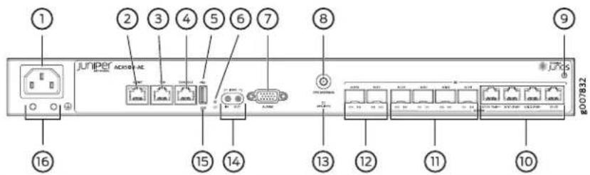
| 9-1- ESD pointAC appliance inlet | |
| Management Ethernet port (MGMT) | 10-Gigabit Ethernet RJ-45 ports (COMBO) |
| 11-Gigabit Ethernet SFP ports (COMBO)Time of day (TOD) | |
| Console port (CONSOLE) | 12-4- Gigabit Ethernet SFP ports |
| USB port | 13-GPS LED (GPS 1PPS) |
| 14-6- External clocking portsRecovery switch | |
| Alarm contact port | 15-System status LED (SYS) |
| 8-GPS antenna port | 16-Grounding terminals |
Figure 14: Front Panel of the ACX500 Indoor Router—DC Chassis
| 1 2 3 4 5 6 7 8 9 10 #000644 17 16 15 14 13 12 11 | |
| 10-1- ESD pointDC terminals | |
| DC power status LED | 11-2 Gigabit Ethernet RJ-45 ports (COMBO) |
| Management Ethernet port (MGMT) | 12-3 Gigabit Ethernet SFP ports (COMBO) |
| Time of day (TOD) RJ-45 port | 13-4- Gigabit Ethernet SFP ports |
| 14-5 GPS LED (GPS 1PPS) Console port (CONSOLE) | |
| 15-6- External clocking portsUSB port | |
| Recovery switch | 16-7 System status LED (SYS) |
| 17-8- Grounding terminalsAlarm contact port | |
| 9-GPS antenna port | |
Related Documentation
ACX500 Universal Access Router Overview on page 3.
• ACX500 Routers Hardware and CLI Terminology Mapping on page 9
• LEDs on ACX500 Routers on page 41
Front Panel of an ACX500 Outdoor Router
The front panel of an ACX500 outdoor router consists of the following components (see Figure 15 on page 36, Figure 16 on page 36, and Figure 17 on page 37):
- Chassis status LED labeled SYS
• USB port for upgrading Junos OS
• Management Ethernet port labeled MGMT
• Time of day (TOD) RJ-45 port - Console port labeled CONSOLE
- Alarm contact port labeled ALARM—accepts a DE-15 alarm cable
- External clocking 1 PPS input and out ports labeled IN and OUT
• GPS clocking LED labeled GPS 1PPS
• Network ports and corresponding status LEDs:
• Three Gigabit Ethernet SFP ports labeled 0/0/0 through 0/0/2
• Three Gigabit Ethernet RJ-45 ports labeled 0/1/0 through 0/1/2
Figure 15: Front Panel of the ACX500 Outdoor Router
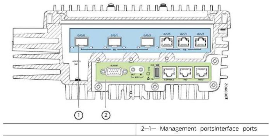
Figure 16 on page 36 shows the ports that are available under the management port cover.
Figure 16: Front Panel of the ACX500 Outdoor Router—Management Ports

Figure 17 on page 37 shows the ports that are available under the interface port cover.
Figure 17: Front Panel of the ACX500 Outdoor Router—Interface Ports

| 3—1— Gigabit Ethernet RJ-45 ports and LEDsGPS LED | |
| 2—Gigabit Ethernet SFP ports and LEDs |
Related Documentation
ACX500 Universal Access Router Overview on page 3.
- ACX500 Routers Hardware and CLI Terminology Mapping on page 9
•LEDs on ACX500 Routers on page 41
Front Panel of an ACX500 Outdoor Router with PoE
The front panel of an ACX500 outdoor router with PoE consists of the following components (see Figure 18 on page 38, Figure 19 on page 38, and Figure 20 on page 39):
- Chassis status LED labeled SYS
• USB port for upgrading Junos OS
• Management Ethernet port labeled MGMT
• Time of day (TOD) RJ-45 port - Console port labeled CONSOLE
- Alarm contact port labeled ALARM—accepts a DE-15 alarm cable
- External clocking 1 PPS input and out ports labeled IN and OUT
• GPS clocking LED labeled GPS 1PPS
• Network ports and corresponding status LEDs:
• Three Gigabit Ethernet SFP ports labeled 0/0/0 through 0/0/2
• Three Gigabit Ethernet RJ-45 ports (with PoE+ support) labeled 0/1/0 through 0/1/2
Figure 18: Front Panel of the ACX500 Outdoor Router with PoE

Figure 19 on page 38 shows the ports that are available under the management port cover.
Figure 19: Front Panel of the ACX500 Outdoor Router with PoE—Management Ports
| Alarm contact port | 6-System status LED (SYS) |
| External clocking ports | 7-Console port (CONSOLE) |
| Recovery switch | 8-Time of day (TOD) RJ-45 port |
| ESD point | 9-Management Ethernet port (MGMT) |
| 5-USB port |
Figure 20 on page 39 shows the ports that are available under the interface port cover.
Figure 20: Front Panel of the ACX500 Outdoor Router with PoE—Interface Ports

| GPS LED | 3-1- Gigabit Ethernet RJ-45 ports (with PoE+ support) and LEDs |
| 2-Gigabit Ethernet SFP ports and LEDs |
Related Documentation
ACX500 Universal Access Router Overview on page 3.
- ACX500 Routers Hardware and CLI Terminology Mapping on page 9
•LEDs on ACX500 Routers on page 41
Alarm Contact Port on ACX500 Routers
The ACX500 router has four external alarm contacts (also known as potential free contacts) for connecting the router to external alarm devices. The port labeled ALARM uses a 15-pin D-type connector. The external alarm contact has 15 pins that accept a single core wire from external alarm devices. A DE15 alarm cable is required to connect the ACX500 router to external alarm devices. Use the gauge wire appropriate for the external device that you are connecting.
Whenever a system condition triggers an alarm, the alarm relay contacts are activated, which in turn activates the external alarm devices. The alarm setting is open or closed.
You can connect and configure two output alarms and four input alarms. Two additional output alarms are reserved and are used to indicate major and minor system alarms. Each output and input alarm has two contacts for connecting the router to external alarm devices. Contact 1 of each alarm can be configured as Normally Open [NO] or Normally Closed [NC] through the CLI. Contact 2 of each alarm functions as a reference [REF] or negative potential terminal for Contact 1 of the corresponding alarm and provides a current path for external alarm devices. Table 9 on page 40 describes the functions of the alarm contacts.
Table 9: Alarm Relay Contact Functions
| Contact Name | FunctionContact Name | |
| Normally Open (NO) | Content 1 is not flowing through Contact 1 and Contact 2 [REF] when operating normally. When the current flows, the closed alarm is generated. | |
| Normally Closed (NC) | Current is flowing through Contact 1 and Contact 2 [REF] when operating normally. When the current stops flowing, the open alarm is generated. | |
| Reference (REF) | Provides the current path for the external alarm-reporting device and functions as a reference or negative potential terminal for Contact 1. |
Figure 21 on page 40 shows an example of a wiring diagram for a simple output alarm-reporting device. In this case the device is a light bulb that illuminates when the device encounters a condition that activates the red alarm LED and relay contacts. The alarm relay contacts can also be used to activate other devices such as bells or buzzers.
Figure 21: Sample Output Alarm-Reporting Device

Figure 22 on page 41 shows an example of a wiring diagram for a simple input alarm-reporting device. In this case the push button switch is an alarm sensor that triggers an input alarm when a door-open condition occurs.
Figure 22: Sample Input Alarm-Reporting Device

Related Documentation
Alarm Contact Port Pinouts for ACX500 Routers on page 75.
LEDs on ACX500 Routers
• System LED on the Front Panel on page 41
• Gigabit Ethernet SFP and RJ-45 Port LEDs on page 41
- Management Port LEDs on the Front Panel on page 42
• GPS 1 PPS LED on the Front Panel on page 42
System LED on the Front Panel
One bicolor LED labeled SYS indicates the status of the router. Table 10 on page 41 describes the system LED in more detail.
Table 10: System LED on the Front Panel
| DescriptionStateColorLabel | ||
| The router is transitioning online.BlinkingGreenSYS | ||
| The router is functioning normally.On steadily | ||
| The router has reported a yellow alarm.BlinkingRed | ||
| On steadythe router has reported a red alarm. |
Gigabit Ethernet SFP and RJ-45 Port LEDs
Each Gigabit Ethernet SFP and RJ-45 port on the front panel of the router has one pair of port LEDs. Table 11 on page 42 describes the LEDs in more detail.
Table 11: Ethernet Port LEDs
| DescriptionStateColorLocationNan | ||||
| The port is receiving data.BlinkingGreenLeftActivity | ||||
| The port is not receiving data.Off- | ||||
| Link | Right | The Yellow online.On | ||
| Off- | No link. |
Management Port LEDs on the Front Panel
The RJ-45 port labeled MGMT has a pair of LEDs that display the status of the port. Table 12 on page 42 describes the LEDs in more detail.
Table 12: Management LEDs
| DescriptionStateColorLocationNan | ||||
| Blinking | ThenportActive and receiving data. | |||
| The port is not receiving data.Off- | ||||
| Link | Right | The Yellow online.On | ||
| Off- | No link. | |||
GPS 1 PPS LED on the Front Panel
One green LED labeled GPS 1PPS indicates the status of the pulse per second (PPS) signal received from the GPS receiver. Table 13 on page 42 describes the LED in more detail.
Table 13: GPS 1 PPS LED on the Front Panel
| DestaptbnStateColor | |||
| GPS 1PPS | Green | Off | PPS signal not received from GPS receiver. |
| Blinking | PPS signal received from GPS receiver. |
Related Documentation
- Troubleshooting Resources for ACX500 Routers on page 175
• Understanding Alarm Types and Severity Classes on ACX Series Routers on page 176 - Front Panel of an ACX500 Indoor Router on page 33
• Uplink Ports on ACX500 Routers on page 43
Uplink Ports on ACX500 Routers
• Gigabit Ethernet RJ-45 Ports on page 43
• Gigabit Ethernet SFP Ports on page 43
• PoE Ports on page 44
Gigabit Ethernet RJ-45 Ports
The Table 14 on page 43 describes the Gigabit Ethernet RJ-45 ports of the ACX500 routers.
Table 14: RJ-45 Port Features
| DescriptionFeature | |
| Supported standards | 10BASE-T Copper100BASE-T1000BASE-T |
| Category 5Cable | |
| RJ-45Connector | |
| Port numbering (hardware) | ACX500 indoor: 0/1/0 PoE++, 0/1/1 PoE+, 0/1/2 PoE+, and 0/1/3ACX500 outdoor: 0/1/0 through 0/1/2 |
| Port numbering (software) | ACX500 Indoor: ge-0/1/0 through ge-0/1/3ACX500 outdoor: ge-0/1/0 through ge-0/1/2 |
Gigabit Ethernet SFP Ports
The Gigabit Ethernet SFP ports located on the front of the chassis enable you to install the Gigabit Ethernet SFP transceivers listed in Table 15 on page 43. The SFP transceivers accept fiber-optic cables.
Table 15: Gigabit Ethernet SFP Port Features
| DescriptionFeature | |
| Supported standards | 1000BASE-EX (model number SFP-GE40KM)1000BASE-LH (model number SFP-1GE-LH-ET)1000BASE-LX (model number SFP-1GE-LX-ET)1000BASE-SX (model numbers SFP-1GE-SX and SFP-1GE-SX-ET) |
| Fiber-optic cableCable | |
| Duplex LC/PC (Rx and Tx)Connector | |
| Port numbering (hardware) | ACX500 indoor: 0/0/0 and 0/0/1, and 0/1/0 through 0/1/3ACX500 outdoor: 0/0/0 through 0/0/2 |
| Port numbering (software) | ACX500 indoor: ge-0/0/0 and 0/0/1, and 0/1/0 through ge-0/1/3ACX500 outdoor: ge-0/0/0 through ge-0/0/2 |
PoE Ports
ACX500 indoor routers and outdoor routers with PoE have a fixed number of Gigabit Ethernet RJ-45 ports, out of which a few are PoE ports. These ports enable you to plug in devices, such as IP phones, wireless access points, and security cameras, that require both network connectivity and electric power. Table 16 on page 44 describes the Gigabit Ethernet PoE ports in more detail.

NOTE: PoEis supported only on the ACX500 indoor and the ACX500 outdoor router with PoE.
Table 16: RJ-45 PoE Port Features
| DescriptionFeature | |
| IEEE 802.3af (PoE) and IEEE 802.3at (PoE+)Supported standards | |
| Per port power limit | PoE++: 65 WPoE+: 35 WNOTE: Total power supported on the PoE ports of the ACX500 routers is 80 W. |
| Copper Ethernet LAN cableCable | |
| RJ-45Connector | |
| Port numbering (hardware) | ACX500 indoor: 0/1/0 PoE++, 0/1/1 PoE+, and 0/1/2 PoE+ACX500 outdoor with PoE: 0/1/0–0/1/2 |
| Port numbering (software) | ACX500 indoor: ge-0/1/0, ge-0/1/1, and ge-0/1/2ACX500 outdoor with PoE: ge-0/1/0, ge-0/1/1, and ge-0/1/2 |
Related Documentation
ACX500 Universal Access Router Overview on page 3.
•Front Panel of an ACX500 Indoor Router on page 33
•Front Panel of an ACX500 Outdoor Router on page 35
•LEDs on ACX500 Routers on page 41
Clocking Ports on ACX500 Routers
The clocking ports distribute a synchronized clock signal throughout the router by locking onto a clock signal originating from an internal clock source or by connecting to an external clock source.
The reference clock inputs can be Ethernet recovered clocks, IEEE 1588v2 recovered clocks, or xDSL NTU-R timing clocks. Externally available reference clocks are 1 pulse per second (PPS). The two SubMiniature B (SMB, 1 PPS input and 1 PPS output) connectors on the front panel of the router connect to external clock signal sources. The clocking ports provide the synchronized output clocks from any one of the above reference inputs based on the clock's priority.
Internal clock sources within the ACX500 routers include:
• 1 PPS SMB connectors (one input and one output)
• Time of day (TOD) RJ-45 port (supports RS-422)
- Synchronous Ethernet support on RJ-45 and SFP ports as timing input or output
- Packet timing (IEEE 1588v2) includes:
- Timing input when configured as ordinary clock (OC) or boundary clock (BC)
- Timing output when configured as BC
Related •External Clocking Ports Specifications on ACX500 Routers on page 77 Documentation •Connecting the ACX500 Router to External Clocking Devices on page 154
CHAPTER 3
Cooling System Components
• Cooling System and Airflow in ACX500 Routers on page 47
Cooling System and Airflow in ACX500 Routers
The ACX500 indoor routers do not contain fans, and are passively cooled through air vents. The air vents in the router are located on both the sides of the router and also on top of the router (see Figure 23 on page 47). Temperature sensors in the chassis monitor the temperature within the chassis. If the temperature inside the chassis rises above the threshold, the router shuts down automatically.
Figure 23: Cooling System and Airflow in the ACX500 Indoor Router
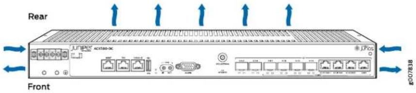
The ACX500 outdoor routers do not contain fans, and are passively cooled by internal heat sinks and external cooling fins (see Figure 24 on page 48). The external cooling fins on the body of the ACX500 outdoor router help to dissipate the heat. Unlike the ACX500 indoor routers, the ACX500 outdoor routers do not have air vents.
Figure 24: Cooling System in the ACX500 Outdoor Routers

1—Cooling fins
Related Documentation
•Site Preparation Checklist for ACX500 Routers on page 53
•Clearance Requirements for Airflow and Hardware Maintenance on ACX500 Routers on page 61
- ACX500 Router Environmental Specifications on page 56
CHAPTER 4
Power System Overview
• ACX500 Power Overview on page 49
ACX500 Power Overview
The ACX500 router is available as DC-powered and AC-powered models. The power supply in the router is built along the front panel of the chassis, with the DC power terminals or AC inlets on the front to connect power to the router.
Table 17 on page 49 and Table 18 on page 49 lists the power consumed by the ACX500 routers.
Table 17: Power Consumed by ACX500 Indoor Routers
| ValueDescription |
Maximum power consumed by the router• 65 W without PoE
• 145 W with maximum PoE load (80 W of PoE)
Table 18: Power Consumed by ACX500 Outdoor Routers
| ValueDescription |
Maximum power consumed by the ACX500 outdoor (ACX500-O): router
- 55 W
ACX500 outdoor with PoE (ACX500-O-POE):
• 55 W without PoE
• 135 W with maximum PoE load (80 W of PoE)
Related Documentation
- ACX500 AC Power Electrical Safety Guidelines and Warnings on page 224
- ACX500 DC Power Electrical Safety Guidelines on page 225
•ACX500 General Electrical Safety Guidelines on page 219
PART 2
Site Planning, Preparation, and Specifications
• Preparation Overview on page 53
• Network Cable and Transceiver Planning on page 71
- Port Cable and Pinout Specifications on page 75
• Power Specifications on page 81
• ACX500 Timing Server Specifications on page 87
CHAPTER 5
Preparation Overview
- Site Preparation Checklist for ACX500 Routers on page 53
- Chassis Physical Specifications for ACX500 Routers on page 54
• ACX500 Router Environmental Specifications on page 56 - Rack Requirements for ACX500 Indoor Routers on page 57
• Cabinet Requirements for ACX500 Indoor Routers on page 58
• Wall Requirements for ACX500 Outdoor Routers on page 60 - Pole Requirements for ACX500 Outdoor Routers on page 60
- Clearance Requirements for Airflow and Hardware Maintenance on ACX500 Routers on page 61
• ACX500 Router Grounding Specifications on page 66 - General Site Guidelines for ACX Series Routers on page 69
Site Preparation Checklist for ACX500 Routers
The checklist in Table 19 on page 53 summarizes the tasks you need to perform when preparing a site for ACX500 router installation.
Table 19: Site Preparation Checklist
| DatePerformed | ||
| Environment | ||
| Verify that environmental factors such as “ACX500 Router Environmental temperature and humidity do not exceed rostercifications” on page 56 tolerances. | ||
| Power | ||
| Measure the distance between external powersources and router installation site. | ||
| Locate sites for connection of system grounding. | “ACX500 Router Grounding Specifications” on page 66 | |
| Calculate the power consumption and requirements. | “ACX500 DC Power Specifications” on page 84 | |
| Hardware Configuration | ||
| Choose the number and types of routers you want to install. | "Rack Requirements for ACX500 Indoor Routers" on page 57 | |
| "Cabinet Requirements for ACX500 Indoor Routers" on page 58 | ||
| "Wall Requirements for ACX500 Outdoor Routers" on page 60 | ||
| "Pole Requirements for ACX500 Outdoor Routers" on page 60 | ||
| Plan rack or cabinet location, including required space clearances. | "Rack Requirements for ACX500 Indoor Routers" on page 57 | |
| "Cabinet Requirements for ACX500 Indoor Routers" on page 58 | ||
| "Wall Requirements for ACX500 Outdoor Routers" on page 60 | ||
| "Pole Requirements for ACX500 Outdoor Routers" on page 60 | ||
| Secure the rack or cabinet to the floor and building structure. | ||
| Cables | ||
| Acquire cables and connectors: | ||
| ·Determine the number of cables needed based on your planned configuration. | ||
| ·Review the maximum distance allowed for each cable. Choose the length of cable based on the distance between the hardware components being connected. | ||
| Plan the cable routing and management. | ||
Related Documentation Installing and Connecting an ACX500 Indoor Router Overview on page 101. •Installing and Connecting an ACX500 Outdoor Router Overview on page 102 •General Site Guidelines for ACX Series Routers on page 69
Chassis Physical Specifications for ACX500 Routers
The ACX500 router is a rigid sheet-metal structure that houses the hardware components. Table 20 on page 55, Table 21 on page 55, and Table 22 on page 55 summarize the physical specifications of the ACX500 routers.
Table 20: Physical Specifications of the ACX500 Indoor Router Chassis
| ValueDescription | |
| 1.75 in. (4.45 cm)Height | |
| Width | • 17.5 in. (44.5 cm)• 19 in. (48.2 cm) with mounting brackets attached |
| 9.4 in. (24 cm)Depth | |
| 8.6 lb (3.9 kg)Weight |
Table 21: Physical Specifications of the ACX500 Outdoor Router Chassis
| ValueDescription | |
| 12.3 in. (31.24 cm)Height | |
| 10 in. (25.4 cm)Width | |
| 4.3 In. (10.92 cm)Depth | |
| Weight | AC-powered: 18.2 lb (8.3 kg)DC-powered: 17.5 lb (7.9 kg) |
Table 22: Physical Specifications of the ACX500 Outdoor Router with PoE Chassis
| ValueDescription | |
| 16 in. (40.64 cm)Height | |
| 10 in. (25.4 cm)Width | |
| 4.7 in. (11.93 cm)Depth | |
| Weight | AC-powered: 18.7 lb (8.5 kg)DC-powered: 18.6 lb (8.4 kg) |
Table 23 on page 55 summarize the weight of the pole-mounting kit and wall-mounting kit.
Table 23: Weight of the Mounting Kits
| ValueDescription | |
| Pole-mounting kit | 2.8 lb (1.3 kg) |
| 2.8 lb (1.3 kg)Wall-mounting kit |
Related Documentation
ACX500 Router Models on page 4.
- ACX500 Router Environmental Specifications on page 56
•Clearance Requirements for Airflow and Hardware Maintenance on ACX500 Routers on page 61
ACX500 Router Environmental Specifications
The ACX500 indoor router must be installed in a rack or cabinet housed in a dry, clean, well-ventilated, and temperature-controlled environment.
Ensure that the following environmental guidelines are followed for the ACX500 indoor router:
- The site must be as dust-free as possible, because dust can clog air intake vents and filters, reducing the efficiency of the router cooling system.
- Maintain ambient airflow for normal router operation. If the airflow is blocked or restricted, or if the intake air is too warm, the router might overheat, leading to the router temperature monitor shutting down the router to protect the hardware components.
- The rack or cabinet must have an adequate supply of cooling air. Allow a minimum of 1 meter/second of airflow over the ACX500 indoor router.

NOTE: Depending on the ambient temperature, it might take up to 5 minutes for the router to heat up to the operating temperature.
Table 24 on page 56 provides the required environmental conditions for normal operation of the ACX500 indoor and outdoor routers.
Table 24: Environmental Specifications
| ValueDescription | |
| No performance degradation up to 3,000 ft (914.4 m)Altitude | |
| Relative humidity | Normal operation ensured in relative humidity range of 5% 95%, noncondensing |
| Temperature | Harsh environment: -40°F (-40°C) through 149°F (65°C), de-rate 1°C for every 1000 ftCentral office environment: 23°F (-5°C) through 131°F (55°C)ACX500 outdoor router with solar loading: 114.8°F (46°C) |
| Commercial grade SFP temperature | Harsh environment: 32°F (0°C) through 122°F (50°C)Central office environment: 32°F (0°C) through 104°F (40°C) |
| Seismic | Designed to meet Telcordia Technologies Zone 4 earthquake requirements |
| Configuration | Harsh environment:PoE Power:PoE++: 65 WPoE+: 35 WNOTE: Total power supported on the PoE ports of the ACX500 routers is 80W.1GB ports: Full trafficSFP/RJ-45 ports: Full trafficSFP: Industrial gradeCentral office environment:1GB ports: Full trafficSFP/RJ-45 ports: Full trafficSFP: Industrial grade |
Related Documentation
Chassis Physical Specifications for ACX500 Routers on page 54.
Rack Requirements for ACX500 Indoor Routers
You can mount the indoor router on two-post racks or four-post racks.
Rack requirements consist of:
- Rack type
- Mounting bracket hole spacing
- Rack size and strength
- Rack connection to the building structure
Table 25 on page 58 provides the rack requirements and specifications for the router.
Table 25: Rack Requirements and Specifications for the ACX500 Indoor Router
| GuidelinesRack Requirement | |
| Rack type | Use a two-post rack or a four-post rack. You can mount the router on any two-post or four-post rack that provides bracket holes or hole patterns spaced at 1 U (1.75 in., or 4.45 cm) increments and that meets the size and strength requirements to support the weight.A UI is the standard rack unit defined in Cabinets, Racks, Panels, and Associated Equipment (document number EIA-310-D) published by the Electronics Industry Association (http://www.eia.org).The rack must meet the strength requirements to support the weight of the chassis. |
| Mounting bracket hole spacing | The holes in the mounting brackets are spaced at 1 U (1.75 in., or 4.45 cm) so that the router can be mounted in any rack that provides holes spaced at that distance. |
| Rack size and strength | ·Ensure that the rack complies with this standard:·A 19-in. (48.3 cm) rack as defined in Cabinets, Racks, Panels, and Associated Equipment (document number EIA-310-D) published by the Electronics Industry Association (http://www.eia.org).·Ensure that the rack rails are spaced widely enough to accommodate the router chassis' external dimensions. The outer edges of the front-mounting brackets extend the width of the chassis to 19.2 in. (48.7 cm).·The rack must be strong enough to support the weight of the router.·Ensure that the spacing of rails and adjacent racks allows for the proper clearance around the router and rack. |
| Rack connection to building structure | ·Secure the rack to the building structure.·If earthquakes are a possibility in your geographical area, secure the rack to the floor.·Secure the rack to the ceiling brackets as well as to the wall or floor brackets for maximum stability. |
| Related Documentation | One pair of mounting brackets for mounting the router on two posts of a rack is supplied with each router. For mounting the router on four posts of a rack or cabinet, you can order a four-post rack mounting kit separately.Cabinet Requirements for ACX500 Indoor Routers on page 58.General Site Guidelines for ACX Series Routers on page 69Installing and Connecting an ACX500 Indoor Router Overview on page 101 |
Cabinet Requirements for ACX500 Indoor Routers
You can mount the indoor router in a cabinet that contains a 19-in. (48.3 cm) rack.
Cabinet requirements consist of:
- Cabinet size
- Clearance requirements
• Cabinet airflow requirements
Table 26 on page 59 provides the cabinet requirements and specifications for the router.
Table 26: Cabinet Requirements and Specifications for the ACX500 Indoor Router
| GuidelinesCabinet Requirement | |
| Cabinet size | You can mount the router in a cabinet that contains a 19-in. (48.3 cm) rack as defined in Cabinets, Racks, Panels, and Associated Equipment (document number EIA-310-D) published by the Electronics Industry Association (http://www.eia.org).NOTE: The cabinet must meet the strength requirements to support the weight of the router.The minimum cabinet size must be able to accommodate the maximum external dimensions of the router. |
| Cabinet clearance | The outer edges of the mounting brackets extend the width of the chassis to 19 in. (48.3 cm).The minimum total clearance inside the cabinet is 30 in. (76.2 cm) between the inside of the front door and the inside of the rear door. |
| Cabinet airflow requirements | When you mount the router in a cabinet, ensure that ventilation through the cabinet is sufficient to prevent overheating.Ensure an adequate cool air supply to dissipate the thermal output of the router or routers.When deploying the router in harsh environments, allow a 1-rack unit (U) gap above and below the router.Minimum 1 meter/second airflow in any directionEnsure that the cabinet allows the hot exhaust air from the chassis to exit the cabinet without recirculating into the router. An open cabinet (without a top or doors) that employs hot air exhaust extraction from the top allows the best airflow through the chassis. If the cabinet contains a top or doors, perforations in these elements assist with removing the hot air exhaust.Install the router in the cabinet in a way that maximizes the open space on the side of the chassis that has the hot air exhaust. This space maximizes the clearance for critical airflow.Route and dress all cables to minimize the blockage of airflow to and from the chassis.Ensure that the spacing of rails and adjacent cabinets allows for the proper clearance around the router and cabinet.A cabinet larger than the minimum required provides better airflow and reduces the chance of overheating. |
Related Documentation
Site Preparation Checklist for ACX500 Routers on page 53.
•Rack Requirements for ACX500 Indoor Routers on page 57
•General Site Guidelines for ACX Series Routers on page 69
- Clearance Requirements for Airflow and Hardware Maintenance on ACX500 Routers on page 61
•Installing and Connecting an ACX500 Indoor Router Overview on page 101
Wall Requirements for ACX500 Outdoor Routers

NOTE: The information provided in this topic is applicable for both the ACX500 outdoor router variants—ACX500 outdoor router and ACX500 outdoor router with PoE.
You can install the ACX500 outdoor router on a wall. When choosing a location, allow at least 6 in. (15.2 cm) of clearance between the sides of the chassis (with the router in installed position) and adjacent equipment or walls. Ensure that the wall onto which the router is installed is stable and securely supported. If you are mounting the router in sheetrock (wall board with a gypsum plaster core) or in wall board not backed by wall studs, use hollow wall anchors capable of supporting the combined weight of two fully loaded chassis. Insert the screws into wall studs wherever possible to provide added support for the chassis.
Use the wall-mounting kit from Juniper Networks to mount the router on a wall. The wall-mounting kit is not part of the standard package and needs to be ordered separately.
Related Documentation
General Site Guidelines for ACX Series Routers on page 69.
• Chassis Physical Specifications for ACX500 Routers on page 54
- ACX500 Router Models on page 4
Pole Requirements for ACX500 Outdoor Routers

NOTE: The information provided in this topic is applicable for both the ACX500 outdoor router variants—ACX500 outdoor router and ACX500 outdoor router with PoE.
You can install the ACX500 outdoor router on a pole. When choosing a location, allow at least 6 in. (15.2 cm) of clearance between the sides of the chassis (with the router in installed position) and adjacent equipment or walls. Ensure that the pole onto which the router is installed is stable and securely supported. Ensure that the pole should be able to carry the load of the fully configured router. The width of the pole must be within the range of 2 in. (5 cm) through 16 in. (40.6 cm) for the pole-mounting brackets to fit properly.
Use the pole-mounting kit from Juniper Networks to mount the router on a pole. The pole-mounting kit is not part of the standard package and needs to be ordered separately.
Related Documentation
General Site Guidelines for ACX Series Routers on page 69.
• Chassis Physical Specifications for ACX500 Routers on page 54
- ACX500 Router Models on page 4
Clearance Requirements for Airflow and Hardware Maintenance on ACX500 Routers
ACX500 Indoor Router Chassis Dimensions and Clearance Requirements
Prepare your site for installation by observing the following guidelines:
- When planning the installation site, allow sufficient clearance around the rack. See Figure 25 on page 61.
- For service personnel to remove and install hardware components, allow at least 2.16 in. (5.5 cm) in front of the router.
- The rack or cabinet must have an adequate supply of cooling air.
- Ensure that the cabinet allows the chassis hot exhaust air to exit from the cabinet without recirculating into the router.
- When deploying the router in harsh environments allow a 1-rack unit (U) gap above and below the router.
- Ensure minimum 1 meter/second airflow in any direction.
Figure 25: ACX500 Indoor Router Chassis Dimensions and Clearance Requirements
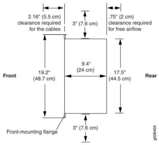
ACX500 Outdoor Router Chassis Dimensions and Clearance Requirements
Prepare your site for installation by observing the following guidelines:
- When installing the ACX500 outdoor routers on a pole or on a wall, the chassis must be installed in a vertical orientation with the cables pointing downward and the eye bolt for hoisting the router pointing upward.
Figure 26 on page 63 and Figure 27 on page 64 show the orientation of the ACX500 outdoor router after installation. - When choosing a location, allow at least 6 in. (15.2 cm) of clearance between the sides of the chassis (with the router in installed position) and adjacent equipment or walls. See Figure 26 on page 63.
- Ensure that the wall or the pole onto which the router is installed is stable and securely supported.
- Ensure that the wall or pole is able to carry the load of the fully configured router.
- If you are mounting the router in wallboard with a gypsum plaster core or in wallboard not backed by wall studs, use hollow wall anchors capable of supporting the combined weight of two fully loaded chassis. Insert the screws into wall studs wherever possible to provide added support for the chassis.
- The width of the pole must be within the range of 2 in. through 16 in. for the pole-mounting brackets to fit properly.
- To mount the router, use the pole-mounting kit or the wall-mounting kit from Juniper Networks.
- One person must be available to lift the router while another secures the router.
- For service personnel to remove and install hardware components, allow at least 24 in. (60.9 cm) on top of the router. See Figure 27 on page 64.
Figure 26: ACX500 Outdoor Router Chassis Dimensions and Clearance Requirements—Front View

Figure 27: ACX500 Outdoor Router Chassis Dimensions and Clearance Requirements—Top View

ACX500 Outdoor Router with PoE Chassis Dimensions and Clearance Requirements
Prepare your site for installation by observing the following guidelines:
- When installing the ACX500 outdoor routers on a pole or on a wall, the chassis must be installed in a vertical orientation with the cables pointing downward and the eye bolt for hoisting the router pointing upward.
Figure 28 on page 65 and Figure 29 on page 66 show the orientation of the ACX500 outdoor router after installation.
- When choosing a location, allow at least 6 in. (15.2 cm) of clearance between the sides of the chassis (with the router in installed position) and adjacent equipment or walls. See Figure 28 on page 65.
- Ensure that the wall or the pole onto which the router is installed is stable and securely supported.
- Ensure that the wall or pole is able to carry the load of the fully configured router.
- If you are mounting the router in wallboard with a gypsum plaster core or in wallboard not backed by wall studs, use hollow wall anchors capable of supporting the combined weight of two fully loaded chassis. Insert the screws into wall studs wherever possible to provide added support for the chassis.
- The width of the pole must be within the range of 2 in. through 16 in. for the pole-mounting brackets to fit properly.
- To mount the router, use the pole-mounting kit or the wall-mounting kit from Juniper Networks.
• One person must be available to lift the router while another secures the router. - For service personnel to remove and install hardware components, allow at least 24 in. (60.9 cm) on top of the router. See Figure 29 on page 66.
Figure 28: ACX500 Outdoor Router with PoE Chassis Dimensions and Clearance Requirements—Front View
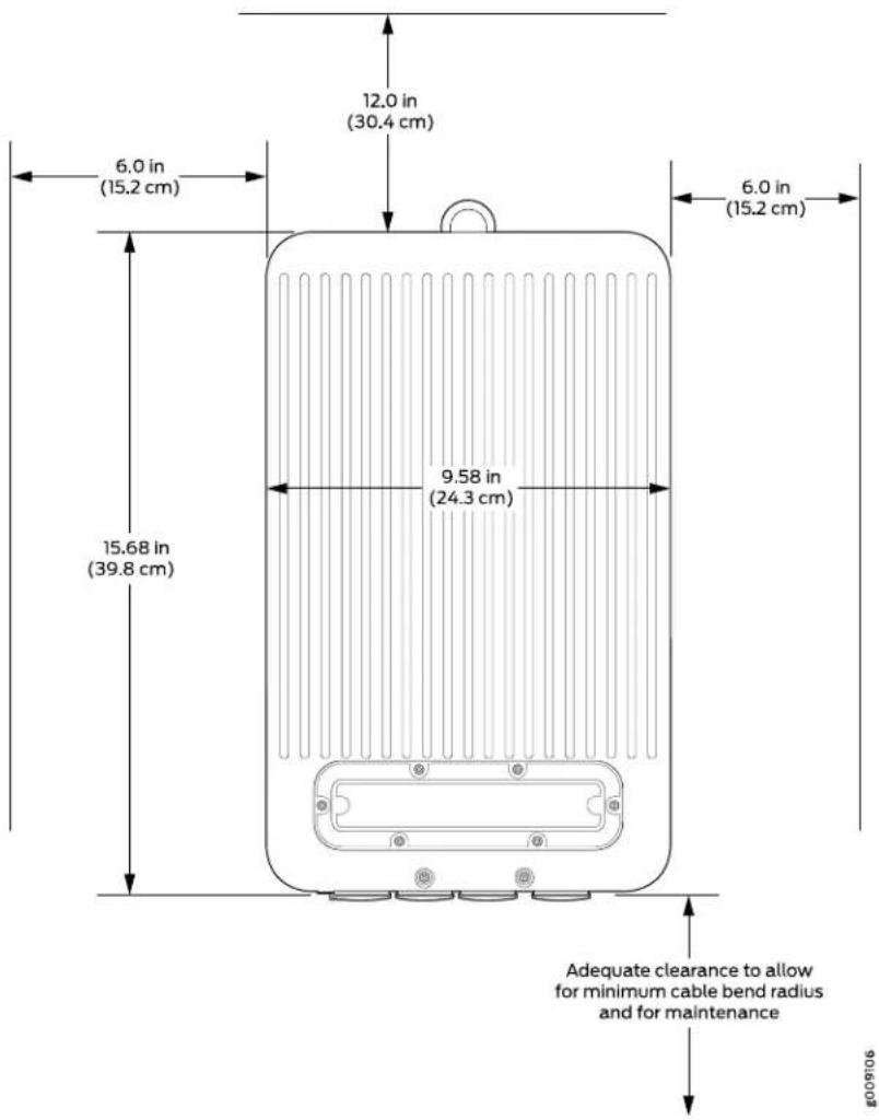
Figure 29: ACX500 Outdoor Router with PoE Chassis Dimensions and Clearance Requirements—Top View

Related Documentation
Site Preparation Checklist for ACX500 Routers on page 53.
•Rack Requirements for ACX500 Indoor Routers on page 57
•Cabinet Requirements for ACX500 Indoor Routers on page 58
•General Site Guidelines for ACX Series Routers on page 69
•Installing and Connecting an ACX500 Indoor Router Overview on page 101
ACX500 Router Grounding Specifications
• Grounding Points Specifications on page 66
• Grounding Cable Lug Specifications on page 68
• Grounding Cable Specifications on page 68
Grounding Points Specifications
To meet safety and electromagnetic interference (EMI) requirements and to ensure proper operation, the router must be adequately grounded before power is connected. To ground the routers, you must connect a grounding cable to earth ground and then attach it to the chassis grounding points by using the two screws provided.
Figure 30 on page 67 shows the grounding points on the ACX500 indoor router, and Figure 31 on page 67 shows the grounding points on the ACX500 outdoor router. The
location of the grounding points for the ACX500 routers is the same for both the AC and the DC variants.
Two threaded holes are provided on the front of the router chassis for connecting the router to earth ground. The grounding points fit 0.5-inch-long SAE 10-32 screws (American). The grounding points are spaced at 0.625 in. (15.86 mm) centers.
Figure 30: Grounding Points on the ACX500 Indoor Routers
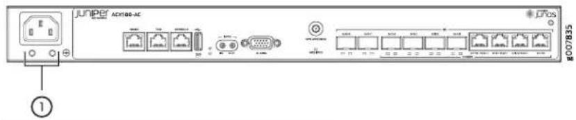
1— Grounding points

NOTE: The location of the grounding points on the ACX500 is the same for both AC-powered and DC-powered models.
Figure 31: Grounding Points on the ACX500 Outdoor Router

natural_image
Technical line drawing of an electronic device housing with internal components and a close-up inset showing pin connections (no text or symbols)
NOTE: The location of the grounding points on the ACX500 is the same for both AC-powered and DC-powered models. The grounding point is located just below the power appliance inlet.

NOTE:
- All baregroundingconnection points totheACX500router must be cleaned and coated with an antioxidant solution before grounding the router.
- All surfaces on the ACX500 router that are unplated must be brought to a bright finish and treated with an antioxidant solution before connecting the router.
- All nonconductive surfaces on the ACX500 must be removed from all threads and connection points to ensure electrical continuity.
- All AC-powered and DC-powered ACX500 routers must be grounded.
Grounding Cable Lug Specifications
The grounding cable lug is used to secure the grounding cable to the grounding points on the ACX Series router chassis. The grounding cable lug attaches to the grounding cable (see Figure 32 on page 68) and is secured to the router by two SAE 10–32 screws of length between 0.25 in. and 0.5 in. The grounding cable lug and screws are not supplied with the router.
Use grounding lug, Panduit LCD6-10A-L or equivalent for the ACX500 indoor router, and Panduit LCCF6-14A-L for the ACX500 outdoor router (not provided).
Figure 32: Grounding Cable Lug


CAUTION: Before routerinstallationbegins, a licensed electrician must attach a cable lug to the grounding and power cables that you supply. A cable with an incorrectly attached lug can damage the router.
Grounding Cable Specifications
You must provide one grounding cable that meets the following specifications: 6-AWG (13.3 mm²), minimum 90°C wire, or as required by the local code.
Related Documentation
Connecting the ACX500 Router to Earth Ground on page 135.
•Preventing Electrostatic Discharge Damage to an ACX500 Router on page 196
General Site Guidelines for ACX Series Routers
Efficient device operation requires proper site planning and maintenance and proper layout of the equipment, rack or cabinet (if used), and wiring closet.
To plan and create an acceptable operating environment for your device and prevent environmentally caused equipment failures:
- Keep the area around the chassis free from dust and conductive material, such as metal flakes.
- Follow prescribed airflow guidelines to ensure that the cooling system functions properly and that exhaust from other equipment does not blow into the intake vents of the router.
- Follow the prescribed electrostatic discharge (ESD) prevention procedures to avoid damaging the equipment. Static discharge can cause components to fail completely or intermittently over time.
- Install the device in a secure area, so that only authorized personnel can access the device.
Related Documentation
•General Safety Warnings for Juniper Networks Devices on page 194
•General Safety Guidelines for Juniper Networks Devices on page 193
• Installation Safety Warnings for Juniper Networks Devices on page 201
CHAPTER 6
Network Cable and Transceiver Planning
• Understanding Fiber-Optic Cable Signal Loss, Attenuation, and Dispersion on page 71
• Calculating Power Budget and Power Margin for Fiber-Optic Cables on page 72
Understanding Fiber-Optic Cable Signal Loss, Attenuation, and Dispersion
This topic describes signal loss, attenuation, and dispersion in fiber-optic cable. For information about calculating power budget and power margin for fiber-optic cable, see "Calculating Power Budget and Power Margin for Fiber-Optic Cables" on page 72 and Supported Network Interface Standards by Transceiver for ACX Series, M Series, MX Ser and T Series Routers or Supported Network Interface Standards by Transceiver for PTX Series Routers.
- Signal Loss in Multimode and Single-Mode Fiber-Optic Cable on page 71
- Attenuation and Dispersion in Fiber-Optic Cable on page 72
Signal Loss in Multimode and Single-Mode Fiber-Optic Cable
Multimode fiber is large enough in diameter to allow rays of light to reflect internally (bounce off the walls of the fiber). Interfaces with multimode optics typically use LEDs as light sources. However, LEDs are not coherent sources. They spray varying wavelengths of light into the multimode fiber, which reflects the light at different angles. Light rays travel in jagged lines through a multimode fiber, causing signal dispersion. When light traveling in the fiber core radiates into the fiber cladding, higher-order mode loss results. Together these factors limit the transmission distance of multimode fiber compared with single-mode fiber.
Single-mode fiber is so small in diameter that rays of light can reflect internally through one layer only. Interfaces with single-mode optics use lasers as light sources. Lasers generate a single wavelength of light, which travels in a straight line through the single-mode fiber. Compared with multimode fiber, single-mode fiber has higher bandwidth and can carry signals for longer distances.
Exceeding the maximum transmission distances can result in significant signal loss, which causes unreliable transmission.
Attenuation and Dispersion in Fiber-Optic Cable
Correct functioning of an optical data link depends on modulated light reaching the receiver with enough power to be demodulated correctly. Attenuation is the reduction in power of the light signal as it is transmitted. Attenuation is caused by passive media components, such as cables, cable splices, and connectors. Although attenuation is significantly lower for optical fiber than for other media, it still occurs in both multimode and single-mode transmission. An efficient optical data link must have enough light available to overcome attenuation.
Dispersion is the spreading of the signal over time. The following two types of dispersion can affect an optical data link:
- Chromatic dispersion—Spreading of the signal over time resulting from the different speeds of light rays.
- Modal dispersion—Spreading of the signal over time resulting from the different propagation modes in the fiber.
For multimode transmission, modal dispersion, rather than chromatic dispersion or attenuation, usually limits the maximum bit rate and link length. For single-mode transmission, modal dispersion is not a factor. However, at higher bit rates and over longer distances, chromatic dispersion rather than modal dispersion limits maximum link length.
An efficient optical data link must have enough light to exceed the minimum power that the receiver requires to operate within its specifications. In addition, the total dispersion must be less than the limits specified for the type of link in Telcordia Technologies document GR-253-CORE (Section 4.3) and International Telecommunications Union (ITU) document G.957.
When chromatic dispersion is at the maximum allowed, its effect can be considered as a power penalty in the power budget. The optical power budget must allow for the sum of component attenuation, power penalties (including those from dispersion), and a safety margin for unexpected losses.
Related Documentation
Calculating Power Budget and Power Margin for Fiber-Optic Cables on page 72.
Calculating Power Budget and Power Margin for Fiber-Optic Cables
Use the information in this topic and the information in Supported Network Interface Standards by Transceiver for ACX Series, M Series, MX Series, and T Series Routers of Supported Network Interface Standards by Transceiver for PTX Series Routers to calculate the power budget and power margin for fiber-optic cables.
To calculate the power budget and power margin, perform the following tasks:
- Calculating Power Budget for Fiber-Optic Cable on page 73
- Calculating Power Margin for Fiber-Optic Cable on page 73
Calculating Power Budget for Fiber-Optic Cable
To ensure that fiber-optic connections have sufficient power for correct operation, you need to calculate the link's power budget, which is the maximum amount of power it can transmit. When you calculate the power budget, you use a worst-case analysis to provide a margin of error, even though all the parts of an actual system do not operate at the worst-case levels. To calculate the worst-case estimate of power _B budget (P you assume minimum transmitter power) (and minimum receiver sensitivity):(P
$$ P _ {B} = P _ {T} - P _ {R} $$
The following hypothetical power budget equation uses values measured in decibels (dB) and decibels referred to one milliwatt (dBm):
$$ P _ {B} = P _ {T} - P _ {R} $$
$$ P _ {B} = - 1 5 \mathrm{dBm} - (- 2 8 \mathrm{dBm}) $$
$$ P _ {B} = 1 3 \mathrm{dB} $$
Calculating Power Margin for Fiber-Optic Cable
After calculating a link's power budget, you can calculate the power margin (P represents the amount of power available after subtracting attenuation or link loss (LL) from the power budget _B ) (PA worst-case estimate of assumes maximum LL:
$$ P _ {M} = P _ {B} - L L $$
P_M greater than zero indicates that the power budget is sufficient to operate the receiver.
Factors that can cause link loss include higher-order mode losses, modal and chromatic dispersion, connectors, splices, and fiber attenuation. Table 27 on page 73 lists an estimated amount of loss for the factors used in the following sample calculations. For information about the actual amount of signal loss caused by equipment and other factors, refer to vendor documentation.
Table 27: Estimated Values for Factors Causing Link Loss
| Estimated Link-Loss ValueLink-Loss Factor | |
| Higher-order mode losses | Single-mode—NoneMultimode—0.5 dB |
| Modal and chromatic dispersion | Single-mode—NoneMultimode—None, if product of bandwidth anddistance is less than 500 MHz-km |
| 0.5 dBConnector | |
| 0.5 dBSplice | |
| Fiber attenuation | Single-mode—0.5 dB/kmMultimode—1 dB/km |
The following sample calculation for a 2-km-long multimode link with a power budget ( P_B ) of 13 dB uses the estimated values from Table 27 on page 73 to calculate link loss (LL) as the sum of fiber attenuation (2 km @ 1 dB/km, or 2 dB) and loss for five connections (0.5 dB per connector, or 2.5 dB) and two splices (0.5 dB per splice, or 1 dB) as well as higher-order mode losses (0.5 dB). The power margins (Calculated as follows:
$$ P _ {M} = P _ {B} - L L $$
$$ P _ {M} = 1 3 \mathrm{dB} - 2 \mathrm{km} (1 \mathrm{dB/km}) - 5 (0. 5 \mathrm{dB}) - 2 (0. 5 \mathrm{dB}) - 0. 5 \mathrm{dB} $$
$$ P _ {M} = 1 3 \mathrm{dB} - 2 \mathrm{dB} - 2. 5 \mathrm{dB} - 1 \mathrm{dB} - 0. 5 \mathrm{dB} $$
$$ P _ {M} = 7 \mathrm{dB} $$
The following sample calculation for an 8-km-long single-mode link with a power budget ( P_B ) of 13 dB uses the estimated values from Table 27 on page 73 to calculate link loss (LL) as the sum of fiber attenuation (8 km @ 0.5 dB/km, or 4 dB) and loss for seven connectors (0.5 dB per connector, or 3.5 dB). The power marginal (Pulated as follows:
$$ P _ {M} = P _ {B} - L L $$
$$ P _ {M} = 1 3 \mathrm{dB} - 8 \mathrm{km} (0. 5 \mathrm{dB/km}) - 7 (0. 5 \mathrm{dB}) $$
$$ P _ {M} = 1 3 \mathrm{dB} - 4 \mathrm{dB} - 3. 5 \mathrm{dB} $$
$$ P _ {M} = 5. 5 \mathrm{dB} $$
In both examples, the calculated power margin is greater than zero, indicating that the link has sufficient power for transmission and does not exceed the maximum receiver input power.
Related Documentation
• Understanding Fiber-Optic Cable Signal Loss, Attenuation, and Dispersion on page 71
CHAPTER 7
Port Cable and Pinout Specifications
- Alarm Contact Port Pinouts for ACX500 Routers on page 75
• External Clocking Ports Specifications on ACX500 Routers on page 77 - Management Port Connector Pinout Information for ACX500 Routers on page 77
- Console Port Connector Pinout on ACX500 Routers on page 78
• ToD RS-422 and 1 PPS RS-422 Port Connector Pinout on ACX500 Routers on page 78
• USB Port Specifications for ACX500 Routers on page 79
Alarm Contact Port Pinouts for ACX500 Routers
You can independently configure alarm input ports (0 through 3) to operate in Normally Open or Normally Closed mode, and to trigger a red alarm condition or a yellow alarm condition, or to ignore alarm conditions.
You can independently configure alarm output ports (0 and 1) to relay alarm information when the system condition goes to a red or yellow alarm condition and when the alarm output port is configured to trigger based on alarm input condition. Alarm output ports (2 and 3) are used to indicate major and minor system alarms and are normally in open mode.
Table 28 on page 75 shows the alarm contact connector pinouts.
Table 28: Alarm Contact Connector Pinouts
| Pin Number | FunctionCLI Port MappingDirectionSignal | |||
| Input Alarm Port 0Input Alarm No/NO/NO/10 (if voltage on this pin is between 24 V to 72 V with reference to Pin 6, alarm input 0 is in closed condition) | ||||
| External alarm input 1 (Reference for Pin 7)Input Alarm Port | ||||
| Input Alarm Port 2Input Alarm No/NO/NO/10 (if voltage on this pin is between 24 V to 72 V with reference to Pin 8, alarm input 2 is in closed condition) | ||||
| Input Alarm Port 3 | External alarm port 3 (if voltage on this pin is between 24 V to 72 V with reference to Pin 8, alarm input 3 is in closed condition) | |||
| OutputALARMOUTA/REF Major alarm | External alarm output 3 (this pin is connected to Pin 10 in closed condition) | |||
| External alarm input 0 (Reference for Pin 1)Input Alarm Port 1 (if voltage on this pin is between 24 V to 72 V with reference to Pin 2, alarm input 1 is closed) | ||||
| Input Alarm Port 1 | ||||
| Input ALARM INPUTA/REF Port 2 and Common contact for external alarm input 3 and Input Alarm Port 3 | ||||
| OutputALARMOUTA/REF Major alarm | External alarm output 2 (this pin is connected to Pin 15 in closed condition) | |||
| OutputALARMOUTA/REF Minor alarm | External alarm output 3 (this pin is connected to Pin 5 in closed condition) | |||
| OutputALARMOUTA/REF Port 0 | External alarm output 0 (this pin is connected to Pin 12 in closed condition) | |||
| OutputALARMOUTA/REF Port 0 | External alarm output 0 (this pin is connected to Pin 11 in closed condition) | |||
| OutputALARMOUTA/REF Port 1 | External alarm output 1 (this pin is connected to Pin 14 in closed condition) | |||
| OutputALARMOUTA/REF Port 1 | External alarm output 1 (this pin is connected to Pin 13 in closed condition) | |||
| OutputALARMOUTA/REF Major alarm | External alarm output 2 (this pin is connected to Pin 9 in closed condition) | |||
Related Documentation
ACX500 Universal Access Router Overview on page 3
- Front Panel of an ACX500 Indoor Router on page 33
• LEDs on ACX500 Routers on page 41
• Alarm Contact Port on ACX500 Routers on page 39
• Understanding Alarm Types and Severity Classes on ACX Series Routers on page 176
External Clocking Ports Specifications on ACX500 Routers
The external clocking port on the ACX500 router contains four SMB connectors that support 1 pulse-per-second (PPS) signal. These signals are internally isolated and have surge protection. Use a Molex 50-ohm SMB connector or equivalent (not provided) to connect to the external clocking ports.
Related Documentation
ACX500 Universal Access Router Overview on page 3.
•Front Panel of an ACX500 Indoor Router on page 33
•LEDs on ACX500 Routers on page 41
•Clocking Ports on ACX500 Routers on page 45
Management Port Connector Pinout Information for ACX500 Routers
The management port—labeled MGMT—on an ACX Series router uses an RJ-45 connector to connect to a management device for out-of-band management.
The port uses an autosensing RJ-45 connector to support a 10/100/1000BASE-T connection. Two LEDs indicate link and /activity on the port and the administrative status of the port.
Table 29 on page 77 provides the pinout information for the RJ-45 connector for the management port.
Table 29: Management Port Connector Pinout Information
| DirectionDescriptionPin | |
| In/OutTRD[0]+1 | |
| In/OutTRD[0]-2 | |
| 3 | In/OutTRD[1]+ |
| 4 | In/OutTRD[2]+ |
| 5 | In/OutTRD[2]- |
| 6 | In/OutPin6 TRD[1]- |
| 7 | In/OutTRD[3]+ |
| 8 | In/OutTRD[3]- |
Related Documentation
ACX500 Universal Access Router Overview on page 3.
•Front Panel of an ACX500 Indoor Router on page 33
•LEDs on ACX500 Routers on page 41
•Alarm Contact Port on ACX500 Routers on page 39
Console Port Connector Pinout on ACX500 Routers
The port labeled CONSOLE on the front panel is an asynchronous serial interface that accepts an RJ-45 connector. Use a cable with the pinouts described in Table 30 on page 78 to connect the Routing Engine to a console management device.

NOTE: You must use a shielded twisted pair (STP) cable for both outdoor and indoor router deployments.
Table 30: Connector Pinout for the Console Port
| DirectionCPUDesc |
1 RTSutRouting EngineRequest to Send
| 2 | NC | No Connect | - | - |
3 TXOutRouting EngineTransmit Data
| 4 | Ground | Signal Ground | - | - |
5 Ground Signal Ground - -
| 6 | RXD: Routing EngineReceive Data |
7 NC No Connect - -
8 CTS Routing EngineClear Ito Send
Related Documentation
ACX500 Universal Access Router Overview on page 3
•Front Panel of an ACX500 Indoor Router on page 33
•LEDs on ACX500 Routers on page 41
•Alarm Contact Port on ACX500 Routers on page 39
ToD RS-422 and 1 PPS RS-422 Port Connector Pinout on ACX500 Routers
The port labeled TOD on the front panel is an asynchronous serial interface that accepts an RJ-45 connector (supports RS-422). Use a cable with the pinouts described in Table 31 on page 79 to connect the Routing Engine to a console management device.
Table 31: Connector Pinout for the TOD RS-422 and 1 PPS RS-422 Ports
| DirectionDescription | |||
| -No ConnectReserve1 | |||
| -No ConnectReserve2 | |||
| OutTx 1PPS negative1PPS_OUT-3 | |||
| -RS-422 level GNDGND4 | |||
| -RS-422 level GNDGND5 | |||
| 6 | 1PPS_OUT+ OutTx 1PPS positive | ||
| 7 | TX- OutTx TOD Time message negative | ||
| 8 | TX+ | Tx TOD time message positive | OUT |
Related Documentation
• ACX500 Universal Access Router Overview on page 3
- Front Panel of an ACX500 Indoor Router on page 33
• LEDs on ACX500 Routers on page 41
• Alarm Contact Port on ACX500 Routers on page 39
USB Port Specifications for ACX500 Routers
The following Juniper Networks USB flash drives have been tested and are officially supported for the USB port on all ACX Series routers:
- RE-USB-1G-S
- RE-USB-2G-S
- RE-USB-4G-S

CAUTION: Any USB memory product not listed as supported for ACX Series routers has not been tested by Juniper Networks. The use of any unsupported USB memory product could expose your ACX Series router to unpredictable behavior. Juniper Networks Technical Assistance Center (JTAC) can provide only limited support for issues related to unsupported hardware. We strongly recommend that you use only supported USB flash drives.
All USB flash drives used on ACX Series routers must have the following features:
- USB 2.0 or later.
- Formatted with a FAT or MS-DOS file system.
Related Documentation
•ACX500 Universal Access Router Overview on page 3
•Front Panel of an ACX500 Indoor Router on page 33
•LEDs on ACX500 Routers on page 41
•Alarm Contact Port on ACX500 Routers on page 39
•Performing Initial Software Configuration for the ACX500 Router on page 155
CHAPTER 8
Power Specifications
• ACX500 AC Power Specifications on page 81
- ACX500 Router AC Power Cord Specifications on page 82
• ACX500 DC Power Specifications on page 84
ACX500 AC Power Specifications
Table 32 on page 81 lists the AC power electrical specifications.
Table 32: AC Power Electrical Specifications
| Item | Specification | ||
| ACX500 Indoor (ACX500-AC) | ACX500 Outdoor (ACX500-O-AC) | ACX500 Outdoor with PoE (ACX500-O-POE-AC) | |
| AC input voltage | Operating range: 100 through 240 VAC | Operating range: 100 through 240 VAC | Operating range: 100 through 240 VAC |
| AC input line frequency | 50 through 60 Hz (nominal) | 50 through 60 Hz (nominal) | 50 through 60 Hz (nominal) |
| rating | 1.4 A (maximum)0.6 A (maximum)1.5 A | ||
| power | 135 W (80 W PoE)55 W145 W (80 W | ||
| power supply output | 128 W (80 W PoE)52 W137 W (80 W | ||

NOTE: We recommend that you use a dedicated customer-site circuit breaker rated for 20 A (100 VAC) or 16 A (240 VAC), or as required by local code. Doing so enables you to operate the router in any configuration without upgrading the power infrastructure.
Related Documentation
ACX500 Power Overview on page 49.
•ACX500 AC Power Electrical Safety Guidelines and Warnings on page 224
•ACX500 General Electrical Safety Guidelines on page 219
ACX500 Router AC Power Cord Specifications
Each AC power supply has a single AC appliance inlet that requires a dedicated AC power feed. Most sites distribute power through a main conduit that leads to frame-mounted power distribution panels, one of which can be located at the top of the rack that houses the router. An AC power cord connects each power supply to the power distribution panel.
You can order detachable AC power cords, each approximately 8 ft (2.5 m) long that supply AC power to the router. The C15 appliance coupler at the female end of the cord, as described by International Electrotechnical Commission (IEC) standard 60320, inserts into the AC appliance inlet coupler. The plug at the male end of the power cord fits into the power source receptacle that is standard for your geographic location.

NOTE: For the ACX500 outdoor routers, use the powercordthatis purchased from Juniper Networks, and which is compatible with the ACX500 outdoor routers. Using a power cord other than that is provided by Juniper Networks with the router can damage the power terminal. The nominal rating of the DC power source are +24 VDC, -48 VDC, and -60 VDC. These power cords are specifically designed to be used only with the specified ACX500 outdoor routers.
Table 33 on page 82 provides specifications for the AC power cord provided for each country or region.
Table 33: AC Power Cord Specifications for the ACX500 Indoor Router
| Design StandardPlu | ||||
| Argentina | CBL-PWR-C15M-HITEMP-AR | 250 VAC, 10 A, 50 Hz | RA/3 | IRAM 2073 |
| Australia | CBL-PWR-C15M-HITEMP-AU | 250 VAC, 10 A, 50 Hz | SAA/3 | AS/NZZS 3112-2000 |
| Brazil | CBL-PWR-C15M-HITEMP-BR | 250 VAC, 10 A, 50 Hz | BR/3 | NBR 14136 |
| China | CBL-PWR-C15M-HITEMP-CH | 250 VAC, 10 A, 50 Hz | PRC/3 | GB2099, GB1002 |
| Europe (except Italy, Switzerland, and United Kingdom) | CBL-PWR-C15M-HITEMP-EU | 250 VAC, 10 A, 50 Hz | VIIG | CEE (7) VII |
| India | CBL-PWR-C15M-HITEMP-IN | 250 VAC, 10 A, 50 Hz | ZA/3 | SABS 164/1:1992 |
| Israel | CBL-PWR-C15M-HITEMP-IL | 250 VAC, 10 A, 50 Hz | IL/3G | SI 32 |
| CEI 23-16I/3G250 V | ||||
| Japan | CBL-PWR-C15M-HITEMP-JP | 125 VAC, 15 A, 50 Hz or 60 Hz | 498GJ | JIS 8303 |
| Korea | CBL-PWR-C15M-HITEMP-KR | 250 VAC, 10 A, 50 Hz | VIIG | CEE (7) VII |
| South Africa | CBL-PWR-C15M-HITEMP-SA | 250 VAC, 10 A, 50 Hz | ZA/3 | SABS 164/1:1992 |
| Switzerland | CBL-PWR-C15M-HITEMP-SZ | 250 VAC, 10 A, 50 Hz | 12G | SEV 1011 / 6534-2 |
| North America | CBL-PWR-C15M-HITEMP-US | 125 VAC, 13 A, 60 Hz | 498G | NEMA 5-15 |
| United Kingdom | CBL-PWR-C15M-HITEMP-UK | 250 VAC, 10 A, 50 Hz | BS89/13 | BS 1363/A |

WARNING: The AC power cord for the router is intended for use with the router only and not for any other use.

WARNING: The attached power cable is only for this product. Do not use the cable for another product. Translation in Japanese follows:
注意
NOTE: In North America, AC power cords must not exceed approximately 14.75 ft (4.5 m) in length, to comply with National Electrical Code (NEC) Sections 400-8 (NFPA 75, 5-2.2) and 210-52, and Canadian Electrical Code (CEC) Section4-010(3). You can order ACpower cordsthat are in compliance.

CAUTION: Power cords and cables must not block access to device components or drape where people could trip on them.

NOTE: The router is rated for ambient temperature of 149^ F ( 65^ C). Use power cord of appropriate temperature rating.
Related Documentation
ACX500 Power Overview on page 49.
- ACX500 AC Power Electrical Safety Guidelines and Warnings on page 224
•ACX500 General Electrical Safety Guidelines on page 219
ACX500 DC Power Specifications
The power supplies in ACX500 routers are built in along the front left panel of the chassis with DC power terminals to connect power to the router. The ACX500 indoor router power supply inputs are labeled INPUT 1 and INPUT 2. On the ACX500 outdoor routers, there are no labels for the DC power supply inlet.

NOTE: For the ACX500 outdoor routers, usethepower cord that is purchased from Juniper Networks, and which is compatible with the ACX500 outdoor routers. Using a power cord other than that is provided by Juniper Networks with the router can damage the power terminal. The nominal rating of the DC power source are +24 VDC, -48 VDC, and -60 VDC. These power cords are specifically designed to be used only with the specified ACX500 outdoor routers.
ACX500 routers support a wide range of voltage ranges as shown in Table 34 on page 84.
Table 34: DC Power Electrical Specifications
| Item | Specification | ||
| ACX500 Indoor(ACX500-DC) | ACX500 Outdoor(ACX500-O-DC) | ACX500 Outdoor with PoE(ACX500-O-POE-DC) | |
| DC input voltages | 20 through 30 VDC:normal 24 VDC-39 through -56 VDC:normal 48 VDC-39 through -72 VDC:normal 60 VDC | 20 through 30 VDC:nominal 24 VDC-39 through -56 VDC:nominal -48 VDC-39 through -72 VDC:nominal -60 VDC | 20 through 30 VDC:nominal 24 VDC-39 through -56 VDC:nominal -48 VDC-39 through -72 VDC:nominal -60 VDC |
| DC input currents | 6.5 A @ 24 VDC3.5 A @ -48 VDC2.5 A @ -60 VDC | 2.5 A @ 24 VDC1.2 A @ -48 VDC1 A @ -60 VDC | 6 A @ 24 VDC3 A @ -48 VDC2.5 A @ -60 VDC |
supply output
135 W (80 W PoE)55 W145 W (80 W F

NOTE: The router with DC power has more than one power source. Ensure proper care while connecting the DC power supply to the router.
To get power feed redundancy on the DC router, you must connect both the power feed from two different source.
Related Documentation
•ACX500 Power Overview on page 49
- ACX500 DC Power Electrical Safety Guidelines on page 225
•ACX500 General Electrical Safety Guidelines on page 219
CHAPTER 9
ACX500 Timing Server Specifications
- Requirements and Specifications for Installing a GNSS Antenna on page 87
- Requirements and Specifications for the Recommended GNSS Antenna on page 95
Requirements and Specifications for Installing a GNSS Antenna
This section describes the guidelines and procedure for installing a global navigation satellite system (GNSS) antenna to ensure an optimal signal reception. The ACX500 routers use the GNSS signals for timing and synchronization features.

NOTE: The GNSS port and LEDs on the ACX500 router chassis are labeled GPS.
Consider the following guidelines before you install the GNSS antenna:
• RF site survey for antenna location
• RF environment details, such as transmission source and proximity
- Grounding plane
- Cable routing
We recommend the guidelines and procedure described in this chapter to ensure optimum GNSS signal reception for the ACX500 router.
- Requirements for Installing a GNSS Antenna on page 88
- ACX500 Router GNSS Antenna Signal Gain Requirements on page 88
- General ACX500 GNSS Antenna Mounting and Installation Recommendations on page 88
- Tools and Parts Required to Install the GNSS Antenna on page 91
• Installing the ACX500 GNSS Antenna on page 92
• ACX500 GNSS Antenna Power Specification on page 93
• ACX500 GNSS Antenna Surge Protection on page 94
- Antenna Installation Verification on page 94
Requirements for Installing a GNSS Antenna
This section describes the requirements to correctly install a GNSS antenna on an ACX500 router. Table 35 on page 88 lists the items that you must provide to install the GNSS antenna.
Table 35: Antenna Mounting Requirements
| Item |
| GNSS L1/G1 antenna with a frequency band of 1575 to 1610 MHz +/-10 MHz, 3 dB bandwidth |
| Antenna mount that is used to secure the GNSS antenna |
| Mounting area clear for at least two meters of any metal or other material that could act as a shield and block the GNSS signal |
| 360° unobstructed clear view of the sky from 15° above horizon |
| Clamps, cable ties, and so on, to secure cable |
ACX500 Router GNSS Antenna Signal Gain Requirements
The ACX500 router requires an active GNSS antenna with built-in low-noise amplifier (LNA) for optimal performance. The LNA amplifies the received satellite signals first to compensate the loss due to the cable, and second to lift the signal amplitude to a range that is required by the receiver.
The cables and connectors that are used to connect the GNSS antenna to the receiver cause signal loss, which can be up to 13 dB. The signal gain due to the LNA amplification can be up to 30 dB.
When calculating the required signal for the router, keep in mind the loss due to the cable and connectors, and the gain due to the LNA amplification. Therefore, if the loss due to the cables and connectors is 13 dB and the LNA signal gain is 30 dB, then the signal gain available to the receiver is 17 dB. We recommend that you limit the available gain to less than 35 dB. Also, ensure that the LNA you select has a low noise profile.
The recommended range of the LNA signal gain, after compensating the loss due to the cables and connectors, at the receiver is 22 dB through 30 dB (with a minimum of 17 dB and a maximum of 35 dB).
General ACX500 GNSS Antenna Mounting and Installation Recommendations
Ideally, the GNSS antenna should be mounted where a 360^ unobstructed clear view of the sky (at 15^ angle from horizontal) is available to enable a connection to visible GNSS satellites. The ideal mounting location is a roof, tower, or an antenna mast, high above any obstruction or any device that can cause signal interference. We recommend a location that has the following characteristics:
- Clear unobstructed view of the sky in all directions— 360^ view.
- Away from high-power transmitters and radar antennas.
- At least 3 feet (1 m) away from any metallic objects, such as radio tower, other antenna mast, electrical poles, and so on.
- At least 3 feet (1 m) below the highest point of a lightning rod.
- Convenient path for running the outdoor coaxial cable from the GNSS antenna to the network.
• Install the router in compliance with the local, national, or international electrical codes:
- United States—National Fire Protection Association (NFPA 70), United States National Electrical Code, Article 810
• Canada—Canadian Electrical Code, Section 54
- Protect the GNSS antenna from environmental conditions such as foot traffic, standing water, and any mechanical stressor that might compromise the cable integrity. Wherever applicable, run smaller size cabling through dedicated outdoor-rated electrical conduit.

WARNING:
- Locate the GNSS antenna away from power lines, lighting systems, HVACs (heating, ventilation and air conditioning), and power circuits.
- When installing the GNSS antenna, do not touch power lines or other sources of "live" power.
- Have a qualified technician or a certified electrician perform the installation.
- Observe all local and regulatory standards and ordinances.
- Grounding the unit (metal mast or ground cable to the unit's base) is required for the lightning protection to work properly.
The ACX500 Timing Server can maintain accurate time even if an antenna is mounted in a location that has limited visibility of GNSS satellites; however, we recommend obstructions should be minimized. Limitations to satellite visibility for an antenna include overhanging foliage or tall structures. Such structures can block the GNSS signal from the antenna and cause gaps in the GNSS satellite signal reception. In locations where satellite visibility is limited, keep in mind the following guidelines:
- Position the antenna on the side of the structure with good visibility toward the equator where more satellites are visible. For example, if you are in the northern hemisphere, place the unit on the southern side of the structure unless that view is restricted or blocked. If that view is restricted or blocked, place the unit on the east or west side of the structure. Avoid the polar side where there are fewer visible satellites.
- Ensure that the GMT time zone parameter is set while you configure the Timing Server.
- To avoid any potential damage to the GNSS antenna and the router, do not install the antenna in the proximity of any transmitting RF or high-voltage power sources. This is both a hardware precaution as well as a personnel safety precaution. Follow all local building code requirements, as well as the local building electrical codes for power and grounding.
- You must mount the antenna above and away from any electrical systems such as lift mechanisms, air handlers, HVACs, and other electrical or mechanical machinery.
- The GNSS signals can be reflected by objects such as metal, walls, and shielded glass parts. Do not install the antenna near good light-reflecting surfaces. Failing to do so might result in distorted GNSS signals.
- To avoid multipath reflections, do not place the antenna near a wall, window, or other large vertical objects.
- To prevent damage from lightning, do not place the GNSS antenna at the highest point of the building.
- You must locate the GNSS antenna at least 3 feet (1 m) away from any metallic objects such as radio tower, other antenna mast, electrical poles, and so on. See Figure 33 on page 91.
- Allow at least 6 feet (2 m) of separation between GNSS antennas. See Figure 33 on page 91.
- The antenna must have an unobstructed 360^ view of the sky from 15^ above the horizon. See Figure 34 on page 91.
- Locate the antenna within a reasonable distance of the building cable entry point.
- Mount the antenna to any fixed surface by using the GNSS antenna mast or stanchion clamp. You may install the antenna to a vertical or horizontal surface based on the surface availability as long as the other antenna placement requirements are met.
- You must connect the GNSS antenna to a surge or lightning arrestor. The surge arrester must be near the antenna location or at the building entrance, and must be grounded to the building ground. This ensures that the antenna has a direct path to ground and is away from any sensitive electrical or electronic GNSS equipment.
- You must protect the GNSS antenna cabling from environmental conditions such as foot traffic, standing water, and any mechanical stress that might compromise or affect the cable integrity. We recommend, where applicable, to run smaller-size cabling through a dedicated outdoor-rated electrical conduit.
Figure 33: Antenna Clearance Requirement—Peripheral
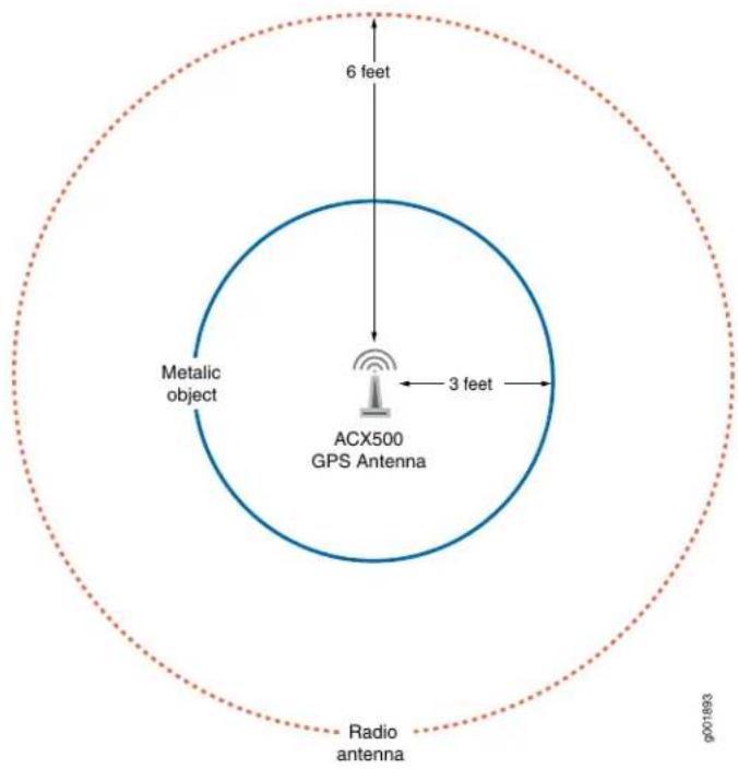
Figure 34: Antenna Clearance Requirement—Field of View

Tools and Parts Required to Install the GNSS Antenna
Table 36 on page 92 lists the parts of a standard GNSS antenna kit and other items required to install the GNSS antenna.
Table 36: Standard Antenna Parts, Tools, and Other Required Items
| Item |
| GNSS L1/G1 antenna with a frequency band of 1575 to 1610 MHz +/-10 MHz, 3 dB bandwidth |
| Antenna mount that is used to secure the GNSS antenna |
| Antenna specific base adaptor |
| Antenna stanchion or mast |
| Antenna-specific cable connector |
| Cable continuity tester |
| Lightning arrestor and grounding strap |
| RF antenna installation kit |
| NO-OX anti-corrosion compound (for cable connections, grounding connector, and ground lugs) |
| Clamps, cable ties, and so on, to secure cable |
Figure 35 on page 92 shows the GNSS antenna parts in a typical installation.
Figure 35: Standard GNSS Antenna Parts
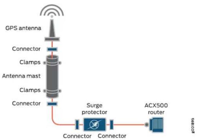
flowchart
graph TD
    A["GPS antenna"] --> B["Connector"]
    B --> C["Clamps"]
    C --> D["Antenna mast"]
    D --> E["Clamps"]
    E --> F["Connector"]
    F --> G["Connector"]
    G --> H["Connector"]
    H --> I["Surge protector"]
    I --> J["ACX500 router"]
Installing the ACX500 GNSS Antenna
To install the GNSS antenna, follow the guidelines specific to the selected GNSS antenna.
The following steps are part of a general procedure for installing any standard GNSS antenna:
- Mount the antenna to any fixed surface by using the GNSS antenna mast or stanchion clamp in an area with clear and open view of the sky.
- Route the coaxial cable from the newly installed antenna into the building following the manufacturer's antenna safety guidelines.
- Route the coaxial cable from the building's head-end to the server's installation site, and connect it to the router's GNSS port (RF input). See "Front Panel of an ACX500 Indoor Router" on page 33 and Figure 5 on page 7 for the GNSS antenna port location on the ACX500 routers.
- Verify that the router is receiving good signal through the GNSS antenna by observing the GPA 1PPS LED on the ACX500 router.

WARNING:
- Have a qualified technician and or certified electrician perform the installation.
- Observe all local and regulatory standards and ordinances.
- Grounding the unit (metal mast or ground cable to the unit's base) is required for the lightning protection to work properly.

WARNING: Do not install the GNSS antenna near overhead power lines or other electric light or power circuits, or where it can come into contact with such circuits. When you install the antenna, take extreme care not to come into contact with such circuits, because they might cause serious injury or death. For proper installation and grounding of the antenna, refer to local, national, and international electrical codes (for example, U.S.: NFPA 70, National Electrical Code, Article 810; Canada: Canadian Electrical Code, Section 54; and so on).
Table 37: Electrical Power Specifications of ACX500 GNSS Output Connector for Antenna Power
| Output Current (mAmp)(I-Load) | Output Voltage (V) |
Vout = 3.3 V (+/-5%) - 22 ohm x I-Load45 mAmp (maximum)

NOTE: ACX500 GNSS output current supports only 3 V antenna voltage, which work with maximum current and supports voltage tolerance as calculated in Table 37 on page 94.
For antennas that do not have a voltage rating of 3 V DC, we recommend that you use an active splitter or amplifier as required (DC block from ACX500 and antenna power from external power source) that supports the antenna voltage.
ACX500 GNSS Antenna Surge Protection
For a roof antenna, we recommend that you provide additional surge protection in accordance to the regulations and standards for lightning protection in the country where the ACX500 router is installed.

NOTE: We recommend that you use an external first-level fast lightning protector that has clamping voltages of 15 V and 20 V.

WARNING: Make sure that grounding is available and that it meets local and national electrical codes. For additional lightning protection, use lightning rods, lightning arrestors, or surge suppressors.
Antenna Installation Verification
After installing the GNSS antenna, verify that the installation is properly done:
- Verify that all the cables and connectors are installed correctly and securely fastened. Ensure that all connectors have been protected from weather by using the latest RF cabling installation and protection guidelines.
- Verify that the GNSS antenna interface status is good in the respective GPS monitoring application. Also, verify the status of the GPS 1PPS LED on the ACX500 router.
- Verify that the cable service loop or the drip loop is utilized and is sufficient.
- Unlike other radio device, do not apply any tape or chemical protection to the connectors. The recommended connectors are weatherproof, and adding any protection makes the warranty void and can lead to expensive repairs.
Related Documentation
Preventing Electrostatic Discharge Damage to an ACX500 Router on page 196.
- Requirements and Specifications for Installing a GNSS Antenna on page 87
Requirements and Specifications for the Recommended GNSS Antenna
• Antenna Selection Guidelines on page 95
- Recommended GNSS Antenna Specifications on page 95
Antenna Selection Guidelines
Keep the following points in mind while selecting the appropriate GPS antenna for the ACX500 router:
- The ACX500 router requires an active GPS antenna with built-in low-noise amplifier (LNA) for optimal performance.
- The ACX500 router supports only 3 V DC voltage. For antennas that do not have a voltage rating of 3 V DC, we recommend that you use an active splitter or amplifier as required (DC block from ACX500 and antenna power from external power source) that supports the antenna voltage. See Table 37 on page 94 for more details on available voltage and current for 3 V antenna application.
- An active splitter or amplifier (DC block from ACX500 and antenna power from external power source) can also be inserted into the antenna path near the receiver for additional gain or added voltage support range. The use of a parasitic nonactive amplifier is not recommend.
Recommended GNSS Antenna Specifications
To use a GNSS antenna with the ACX500 router, the antenna must be a GNSS L1/G1 antenna (1575–1610 MHz). At present there are several GNSS antennas available in the market that meet the ACX500 router criteria.
We recommend that you use the following GNSS antenna with the ACX500 routers:
- Trimble Bullet 38dB GPS L1 Antenna Specifications on page 95
Trimble Bullet 38dB GPS L1 Antenna Specifications
The Trimble Bullet III GPS L1 antenna boosts the signal from the antenna with a gain of 38 dB. The antenna receives power, rated at 3.3 VDC, from the ACX500 router through the antenna's coaxial cable connections.
Table 38 on page 95 lists the Trimble Bullet GPS antenna specifications.
Table 38: Trimble Bullet 38dB GPS L1 Antenna Specifications
| SpecificationParameter | |
| Electrical Specifications | |
| +3.3 VDC (+/-10%)Prime power | |
| < 30 mA maximumPower consumption | |
| 38 dB +/- 3 dBGain | |
| 50 ohmsOutput impedance | |
| 1575.42 MHz +/- 3 MHzFrequency | |
| Right-hand circular polarization (RHCP)Polarization | |
| ≤ 2.0:1Voltage standing wave ratio (VSWR) | |
| < 3 dB maximumAxial ratio | |
| 2.0 dB (typical)Noise | |
| 25 MHz (min)Bandwidth (10dB RL) | |
| Out-of-band rejection | fo = 1575.42 MHzfo +/-50 MHz: 30 dB typicalfo +/-100 MHz: 40 dB typical |
| 360° (omnidirectional)Azimuth coverage | |
| Elevation coverage | 0° through 90° elevation (hemispherical) |
| Environmental Specifications | |
| Operating temperature | -40 °C through +90 °C |
| Storage temperature | -40 °C through +90 °C |
| Vibration | 10-200 Hz log sweep |
| 3 g (Sweep time 30 minutes) | 3 axes |
| Shock | 50 g vertical, 30 g all axes |
| Humidity | +60°C @ 95% RH |
| 5% salt sprayCorrosion | |
| Waterproof | Immersion to 1 meter |
| Physical Specifications | |
| Dimensions | 3.05 in. (77.5 mm) deep × 2.61 in. (66.2 mm)high0.44 lb (0.2 kg)Weight |
| TNC (3.3 VDC)Connector | |
| 3/4 in. pipe thread or 1–14 in. threadMounting | |
Table 39 on page 97 lists the specifications of the cable to be used with the Trimble GPS antenna.
Table 39: Antenna Cable Specification for Trimble Bullet 38dB GPS L1 Antenna
| Loss BudgetMaximum Le | |||
| L1 Antenna 3V (38dB gain) | 10 dB/100 feet150 feet (50 meters)LMR-24 | ||
| LMR400 | 300 feet (100 meters) | 5.2 dB/100 feet |

NOTE: Do not use coaxial cable type RG-58 for GNSS antenna. Use coaxial cable type RG-6 or the cables mentioned in Table 39 on page 97.
Related Documentation - Preventing Electrostatic Discharge Damage to an ACX500 Router on page 196 - Requirements and Specifications for the Recommended GNSS Antenna on page 95
PART 3
Initial Installation and Configuration
• Installation Overview on page 101
- Unpacking the ACX500 Router on page 105
• Installing the ACX500 Router on page 109
- Connecting the ACX500 to Ground on page 135
• Providing Power to the ACX500 on page 139
- Connecting the ACX500 to External Devices on page 151
- Configuring Junos OS on ACX500 Routers on page 155
CHAPTER 10
Installation Overview
• Installing and Connecting an ACX500 Indoor Router Overview on page 101
• Installing and Connecting an ACX500 Outdoor Router Overview on page 102
Installing and Connecting an ACX500 Indoor Router Overview
To install and connect an ACX500 indoor router:
- Unpack the router and verify the parts received. See "Unpacking the ACX500 Router" on page 107.
- Install the router. See "Installing the ACX500 Indoor Router in a Rack" on page 109.
- Ground the router. See "Connecting the ACX500 Router to Earth Ground" on page 135.
-
Connect power to the router.
-
AC-powered models—See “Connecting an AC Power Cord to the ACX500 Indoor Router” on page 139.
-
DC-powered models—See “Connecting DC Power Cables to the ACX500 Indoor Router” on page 140
-
Connect the router to external devices. See:
-
Connecting ACX500 Routers to Management Devices on page 151
- Connecting the ACX500 Router to an External Alarm-Reporting Device on page 153
- Connecting the ACX500 Router to External Clocking Devices on page 154
-
Requirements and Specifications for Installing a GNSS Antenna on page 87
-
Perform initial configuration of the router. See "Performing Initial Software Configuration for the ACX500 Router" on page 155.
Related Documentation
Site Preparation Checklist for ACX500 Routers on page 53.
•General Site Guidelines for ACX Series Routers on page 69
- ACX500 Router Models on page 4
Installing and Connecting an ACX500 Outdoor Router Overview

NOTE: The information provided in this topic is applicable for both the ACX500 outdoor router variants—ACX500 outdoor router and ACX500 outdoor router with PoE.
Based on your need, you can install the ACX500 outdoor router in one of the following ways:
- “Mounting the ACX500 Outdoor Router on a Pole” on page 116 — You can mount the ACX500 outdoor router on a suitable telephone or an electrical pole with help of the pole-mounting kit. The pole-mounting kit is sold separately. It is not shipped with the ACX500 outdoor router.
- "Mounting the ACX500 Outdoor Router on a Wall" on page 111 — You can mount the ACX500 outdoor router on a suitable wall with the help of a wall-mounting kit. The wall-mounting kit is sold separately. It is not shipped with the ACX500 outdoor router.
To install and connect an ACX500 outdoor router:
- Unpack the router and verify the parts received. See "Unpacking the ACX500 Router" on page 107.
-
Install the router.
-
On a pole—See “Mounting the ACX500 Outdoor Router on a Pole” on page 116.
-
On a wall—See "Mounting the ACX500 Outdoor Router on a Wall" on page 111.
-
Ground the router. See "Connecting the ACX500 Router to Earth Ground" on page 135.
-
Connect power to the router.
-
AC-powered models—See “Connecting an AC Power Cord to the ACX500 Outdoor Router” on page 142.
-
DC-powered models—See “Connecting a DC Power Cord to the ACX500 Outdoor Router” on page 146.
-
Connect and secure the interface cables to the router. See "Weatherproofing the ACX500 Outdoor Router" on page 121.
-
Connect the router to external devices. See:
-
Connecting ACX500 Routers to Management Devices on page 151
- Connecting the ACX500 Router to an External Alarm-Reporting Device on page 153
-
Connecting the ACX500 Router to External Clocking Devices on page 154
-
Perform initial configuration of the router. See "Performing Initial Software Configuration for the ACX500 Router" on page 155.
Related Documentation
•Site Preparation Checklist for ACX500 Routers on page 53
•General Site Guidelines for ACX Series Routers on page 69
- ACX500 Router Models on page 4
CHAPTER 11
Unpacking the ACX500 Router
- Parts Inventory (Packing List) for ACX500 Routers on page 105
- Unpacking the ACX500 Router on page 107
Parts Inventory (Packing List) for ACX500 Routers
The ACX500 routers are shipped in a cardboard carton, secured with foam packing material. The carton also contains an accessory box.
The router shipment includes a packing list. Check the parts you receive in the router shipping carton against the items on the packing list. The packing list specifies the part number and description of each part in your order. The parts shipped depend on the configuration you order.
If any part on the packing list is missing, contact your customer service representative or contact Juniper Customer Care from within the U.S. or Canada by telephone at 1-888-314-5822. For international-dial or direct-dial options in countries without toll-free numbers, see http://www.juniper.net/support/requesting-support.html.
Table 40 on page 105 and Table 41 on page 106 list the parts and their quantities in the packing list.

NOTE: You must provide additional mounting screws if needed that are appropriate for your rack or cabinet to mount the ACX500 indoor chassis on a rack or a cabinet.
Table 40: Parts List for an ACX500 Indoor Router
| QuantityCompo | |
| 1Router with built-in power supply | |
| 2Mounting brackets | |
| 8Mounting screws to attach the | |
| 6SFP dust cover | |
| 1RJ-45 cable and RJ-45 to DB-9 | |
| 1Quick Start installation instruction | |
| 1Juniper Networks Product Warrar | |
| 1End User License Agreement |
Table 41: Parts List for an ACX500 Outdoor Router
| QuantityCompon | |
| 1Router with built-in power supply | |
| 6SFP dust cover | |
| 1RJ-45 cable and RJ-45 to DB-9 s | |
| 1Quick Start installation instructions | |
| 1Juniper Networks Product Warranty | |
| 1End User License Agreement |

NOTE: The AC power cord or the DC power cord for the ACX500 outdoor routers is not shipped with the router. You need to purchase it separately.
Use the power cord that is purchased from Juniper Networks, and that is compatible with the ACX500 outdoor routers. Using a power cord other than that is provided by Juniper Networks with the router can damage the power terminal.
Table 42 on page 106 and Table 43 on page 107 list the parts and their quantities in the wall-mounting and pole-mounting kits required for installing the outdoor router.

NOTE: The wall-mounting and the pole-mounting kits are not provided with the router. You need to purchase the mounting kits separately.
Table 42: Parts List for the Wall-Mounting Kit
| QuantityComponent | |
| 1Wall-mounting bracket | |
| 1Chassis-mounting bracket | |
| 4Nuts | |
| 10Screws | |
| 14Washers |
Table 43: Parts List for the Pole-Mounting Kit
| QuantityComponent | |
| 1Pole-mounting bracket | |
| 1Chassis-mounting bracket | |
| 4Nuts | |
| 10Screws | |
| 14Washers | |
| Pole-mounting strap and screw | 3 |
Related Documentation
ACX500 Universal Access Router Overview on page 3
- Unpacking the ACX500 Router on page 107
Unpacking the ACX500 Router
The ACX500 routers are shipped in a cardboard carton, secured with foam packing material. The carton also contains an accessory box.

CAUTION: ACX500 routers are maximally protected inside the shipping carton. Do not unpack the routers until you are ready to begin installation.
To unpack the router and prepare for installation, you need the following tools:
- Blank panels to cover any slots not occupied by a component
To unpack the router:
- Move the shipping carton to a staging area as close to the installation site as possible, but where you have enough room to remove the system components.
- Position the carton so that the arrows are pointing up.
- Open the top flaps on the shipping carton.
- Remove the accessory box, and verify the contents in it against the parts inventory on the label attached to the carton.
- Pull out the packing material holding the router in place.
- Verify the chassis components received against the packing list included with the router. An inventory of parts provided with the router is provided in "Parts Inventory (Packing List) for ACX500 Routers" on page 105.
- Save the shipping carton and packing materials in case you need to move or ship the router later.
Related Documentation
•ACX500 Universal Access Router Overview on page 3
•Site Preparation Checklist for ACX500 Routers on page 53
CHAPTER 12
Installing the ACX500 Router
• Installing the ACX500 Indoor Router in a Rack on page 109
- Mounting the ACX500 Outdoor Router on a Wall on page 111
- Mounting the ACX500 Outdoor Router on a Pole on page 116
- Weatherproofing the ACX500 Outdoor Router on page 121
Installing the ACX500 Indoor Router in a Rack

NOTE: Therouter must be installed horizontally in a rack or cabinet. The term rack is used to mean rack or cabinet.
Ensure that you have the following parts and tools available:
• Phillips (+) screwdriver, number 2
- Two mounting brackets for front or rear mounting are shipped with the router (see Figure 36 on page 110 and Figure 37 on page 110).

CAUTION: Before front mounting the router in a rack, have a qualified technician verify that the rack is strong enough to support the router's weight (about 8.6 lb (3.9 kg)) and is adequately supported at the installation site.

NOTE: One person must be available to lift the router while another secures it to the rack.

CAUTION: If you are mounting multiple units on a rack, mount the heaviest unit at the bottom of the rack, and mount the other units from the bottom of the rack to the top in decreasing order of the weight of the units.
To install the router in the rack:
- Install both mounting brackets to either the front or rear of the chassis:
a. Align the bracket with the two sets of mounting holes.
b. Insert the four screws at the top and bottom of the bracket, and tighten each partially.
c. Tighten the four screws completely.
d. Repeat the procedure for the other bracket.
Figure 36: Installing the Mounting Brackets to the Front of the ACX500 Router
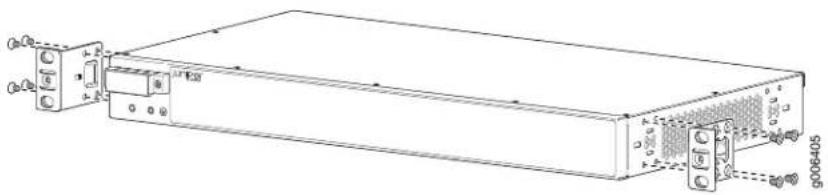
natural_image
Technical line drawing of a rectangular electronic device with ports and connectors (no text or symbols)Figure 37: Installing the Mounting Brackets to the Rear of the ACX500 Router
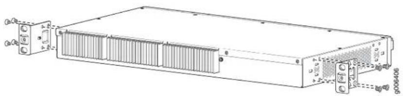
natural_image
Technical line drawing of a rectangular electronic device with cooling fins and mounting brackets (no text or symbols)-
Ensure that the rack is in its permanent location and is secured to the building. Ensure that the installation site allows adequate clearance for both airflow and maintenance.
-
Position the router in front of the rack or cabinet.
-
Hold onto the bottom of the chassis, and carefully lift it so that the mounting brackets contact the rack rails. See Figure 38 on page 111.

WARNING: To prevent injury, keep your back straight and lift with your legs, not your back. Avoid twisting your body as you lift. Balance the load evenly and be sure that your footing is solid.
Figure 38: Installing the ACX500 Indoor Router in the Rack
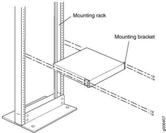
-
Align the mounting brackets with the holes in the rack rails.
-
Install a mounting screw into each of the open mounting holes on the mounting bracket aligned with the rack, starting from the bottom.
-
Visually inspect the alignment of the router. If the router is installed properly in the rack, all the mounting screws on one side of the rack should be aligned with the mounting screws on the opposite side, and the router should be level.
Related Documentation
Site Preparation Checklist for ACX500 Routers on page 53.
•Installing and Connecting an ACX500 Indoor Router Overview on page 101
•Connecting the ACX500 Router to Earth Ground on page 135
Mounting the ACX500 Outdoor Router on a Wall

NOTE: The information provided in this topic is applicable for both the ACX500 outdoor router variants—ACX500 outdoor router and ACX500 outdoor router with PoE.
You can mount the ACX500 outdoor router on the wall with the help of a wall-mounting kit. The ACX500 wall-mounting kit consists of two mounting brackets (one is attached to the rear of the ACX500 outdoor router and the other to the wall).
The ACX500 outdoor router meets the requirement of the International Protection Code (IP65) for dust-tight environments and ingress of water jets.
The wall on which you want to install the ACX500 outdoor router along with the wall-mounting kit must have the following:
- When installing the ACX500 outdoor routers on a wall, the chassis must be installed in a vertical orientation with the cables pointing downward and the eye bolt for hoisting the router pointing upward.
- The strength and thickness of the wall must safely support the total weight of the router chassis, including the mounting brackets and cables, and must comply with local standards and practices.
- The wall must be able to support the weight of the fully configured router (router chassis and mounting kit).
The AC-powered ACX500 outdoor router weighs 18.2 lb (8.3 kg), and the DC-powered router weighs 17.5 lb (7.9 kg). The AC-powered ACX500 outdoor router with PoE weighs 18.7 lb (8.5 kg), and the DC-powered router with PoE weighs 18.6 lb (8.4 kg). The wall-mounting kit weighs 2.8 lb (1.3 kg).
- When choosing a location, allow at least 6 in. (15.2 cm) of clearance between the sides of the chassis (with the router in the installed position) and adjacent equipment or walls.
- Ensure that the wall is stable and securely supported.
- If you are mounting the router in wallboard with a gypsum plaster core or in wallboard not backed by wall studs, use hollow wall anchors capable of supporting the combined weight of two fully loaded chassis. Insert the screws into wall studs wherever possible to provide added support for the chassis.
- To mount the router, use the wall-mounting kit from Juniper Networks.
- The wall-mounting kit is not part of the standard package and must be ordered separately.
- For service personnel to remove and install hardware components, allow at least 24 in. (60.9 cm) on top of the router.
Ensure that you have the following parts and tools available:
- Phillips (+) screwdriver with a minimum shaft length of 6 in. (150 mm)
• 3/8 in. ratchet driver set
- An electrostatic discharge (ESD) grounding strap
• Wall-mounting kit (to be purchased separately)
- Based on the wall type, appropriate screws to secure the wall-mounting bracket on the wall (not provided)
- Ground label and ground lug provided with the wall-mounting kit
- Marker pen
- Drilling machine
To mount the ACX500 outdoor router on a wall:
- Attach an ESD grounding strap to your bare wrist, and connect the strap to one of the ESD points on the chassis.
- Align and attach the chassis-mounting bracket and the wall-mounting bracket provided with the wall-mounting kit, and secure the two brackets with the set of four bracket screws, washers, and nuts. See Figure 39 on page 113.

NOTE: Apply between 50 lb-in. (5.7 Nm) and 60 lb-in. (6.8 Nm) of torque on the screws to ensure that both the brackets are held tightly.
Figure 39: Wall-Mounting Kit

| 4-1- Wall-mounting bracketScrew | |
| 5-2- Flat washerSplit washer | |
| Chassis-mounting bracket | 6-3- Nut |
- Place the joined brackets on the wall where you want to install the outdoor router with the wall-mounting bracket facing the wall, and mark the four wall-mounting screw hole points on the wall.

NOTE: The router must be mounted keeping in mind the basic clearance requirement for the ACX500 outdoorrouter. See "Clearance Requirements for Airflow and Hardware Maintenance on ACX500 Routers" on page 61 for more information.
-
Remove the bracket, and drill four holes at the points marked on the wall.
-
Install mounting screws (to anchor the router) into the top two drill holes until you have 1/4 in. of the screws left.

NOTE:
- The mounting screws are not provided. The size and strength of the mounting screws must safely support the total weight of the router chassis, including the mounting brackets and cables, and must comply with the local standards and practices.
- It is important to leave 1/4 in. of the screw. The keyholes on the wall-mounting bracket align with these screws and help hang the wall-mounting kit on the wall.
- Carefully align the wall-mounting bracket keyholes of the joined brackets and hang it on the two screws that were secured on the wall in step 5. See Figure 40 on page 114.
Figure 40: Installing the Wall-Mounting Kit

| 3-1- Chassis-mounting bracketWall-mounting bracket keyhol | |
| 4-2- Wall-mounting bracketChassis-mounting bracket keyhol |
-
Pull the wall-mounting kit gently down so that it sits tightly on the screws.
-
Insert two mounting screws onto the bottom wall-mounting holes to completely secure the wall-mounting kit to the wall.
-
Lift and carry the ACX500 outdoor router to the wall where the wall-mounting kit is attached.
The small eye bolt at the top of the ACX500 outdoor router can be used to lift the chassis. Use an appropriate rope and lifting tool to hoist the router at the desired height.
One person must be available to lift the router while another secures the router.
- Insert two mounting screws on the top of the outdoor router and secure the screws.
The ACX500 outdoor router is secured onto the wall-mounting kit with the help of six screws. The top two screws are inserted first into the keyholes on the wall-mounting kit. These screws help to first hang the router on the wall-mounting kit by taking the weight out, and when the router comfortably hangs on the unit, secure it by using the other four screws.
- Align the router carefully and then insert the top two chassis-mounting screws attached to the router in step 10 into the chassis-mounting bracket keyholes. See Figure 41 on page 116.

NOTE: Ensure that the chassis-mounting screws sit properly in the chassis-mounting bracket keyholes.
Figure 41: Installing the ACX500 Outdoor Router onto the Wall-Mounting Kit

| 5-1- Chassis-mounting bracketEye bolt | |
| 6-2- WallRouter | |
| 7-3- Middle chassis-mounting screwTop chassis-mounting s | |
| 8-4- Bottom chassis-mounting screwWall-mounting bracket |
- After the router comfortably hangs on the wall-mounting kit, secure it by using the other four chassis-mounting screws (two screws on the middle and two on the bottom of the outdoor router).
The ACX500 outdoor router is now securely mounted on the wall and ready to use. Connect the power supply and cabling as required.
Related Documentation
Site Preparation Checklist for ACX500 Routers on page 53.
• Installing and Connecting an ACX500 Outdoor Router Overview on page 102
- Connecting the ACX500 Router to Earth Ground on page 135
• Chassis Physical Specifications for ACX500 Routers on page 54
Mounting the ACX500 Outdoor Router on a Pole

NOTE: The information provided in this topic is applicable for both the ACX500 outdoor router variants—ACX500 outdoor router and ACX500 outdoor router with PoE.
You can mount the ACX500 outdoor router on a pole with the help of a pole-mounting kit. The ACX500 pole-mounting kit consists of two mounting brackets (one is attached to the rear of the ACX500 outdoor router and the other to the pole), 5/8-in. through bolts and pole straps.
The ACX500 outdoor router meets the requirement of the International Protection Code (IP65) for dust-tight environments and ingress of water jets.
The pole on which you want to install the ACX500 outdoor router along with the pole-mounting kit must satisfy the following requirements:
- When installing the ACX500 outdoor router on a pole, the chassis must be installed in a vertical orientation with the cables pointing downward and the eye bolt for hoisting the router pointing upward.
- The strength and thickness of the pole must safely support the total weight of the router chassis, including the mounting brackets and cables, and must comply with local standards and practices.
- The pole must be able to support the weight of the fully configured router (router chassis and mounting kit).
The AC-powered ACX500 outdoor router weighs 18.2 lb (8.3 kg), and the DC-powered weighs 17.5 lb (7.9 kg). AC-powered ACX500 outdoor router with PoE weighs 18.7 lb (8.5 kg), and the DC-powered router weighs 18.6 lb (8.4 kg). The pole-mounting kit weighs 2.8 lb (1.3 kg).
- Ensure that the pole is stable and securely supported.
- The width of the pole must be within the range of 2 in. through 16 in. to hold the pole-mounting kit.
- To mount the router, use the pole-mounting kit from Juniper Networks.
Ensure that you have the following parts and tools available:
- Phillips (+) screwdriver with a minimum shaft length of 6 in. (150 mm)
• 3/8 in. ratchet driver set - An electrostatic discharge (ESD) grounding strap
- Pole-mounting kit (to be purchased separately)
- Ground label and ground lug provided with the pole-mounting kit
To mount the ACX500 outdoor router on a pole:
- Attach an ESD grounding strap to your bare wrist, and connect the strap to one of the ESD points on the chassis.
- Align and attach the chassis-mounting bracket and the pole-mounting bracket provided with the pole-mounting kit, and secure the two brackets with the set of four bracket screws, washers, and nuts. See Figure 42 on page 118.

NOTE: Apply between 50 lb-in. (5.7 Nm) and 60 lb-in. (6.8 Nm) of torque on the screws to ensure that both the brackets are held tightly.
Figure 42: Pole-Mounting Kit

| 5-1- Pole-mounting bracketScrew | |
| 6-2- Pole-mounting strapsSplit washer | |
| 7-3- Flat washerChassis-mounting bracket | |
| 8-4- NutHole for through bolt |
- Insert the pole-mounting straps through the pole-mounting strap holes on the pole-mounting bracket. See Figure 43 on page 119.
Figure 43: Installing the ACX500 Outdoor Router onto the Pole-Mounting Kit

| 7-1-Pole-mounting strap screwRouter | |
| 8-2-Pole-mounting strapEye bolt | |
| 9-3-Pole-mounting bracketTop chassis-mounting screw | |
| 10-4-Bottom chassis-mounting screwChassis-mounting brack | |
| 11-5-Middle chassis-mounting screwChassis-mounting brack | |
| 6-Pole |
- Place the joined brackets on the pole where you want to install the ACX500 outdoor router with the pole-mounting bracket facing the pole, and secure the joined brackets with the three 5/8-in. through bolts provided.
The three holes present on the pole-mounting brackets are for the through bolts.
- Wrap the pole-mounting straps across the pole, and secure the straps with the pole-mounting strap screws.

NOTE: Apply 20 lb-in. (2.3 Nm) of torque on the screws to ensure that both the brackets are held tightly.
- On the bottom of the router (that is, the surface that will face the pole), secure two keyhole mounting screws in to the top two chassis-mounting screw holes.
The ACX500 outdoor routers has six screw holes at the bottom of the chassis—two on top, two on center, and two on bottom. The center and bottom screw holes are for normal screws while the top screw holes are for keyhole screws.

NOTE: Ensure that the top two chassis-mounting screws are secured tightly in to the chassis as these screws will hold the entire weight of the chassis initially when attached to the wall.
- Lift and carry the ACX500 outdoor router to the pole where the pole-mounting kit is attached. See Figure 44 on page 120.
The small eye bolt at the rear of the ACX500 outdoor router can be used to lift the chassis. Use an appropriate rope and lifting tool to hoist the router at the planned height.
One person must be available to lift the router while another secures the router.
Figure 44: Securing the ACX500 Outdoor Router on the Pole
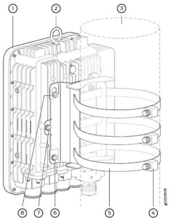
| 5-1- Pole-mounting strapRouter | |
| 6-2- Bottom chassis-mounting screwEye bolt | |
| 7-3- Middle chassis-mounting screwPole | |
| 4-Pole-mounting strap screw | 8-Top chassis-mounting screw |
- Align and insert the top two chassis-mounting screws attached to the router in step 6 into the chassis-mounting bracket keyholes.

NOTE: Ensure that the chassis-mounting screws sit properly in the chassis-mounting bracket keyholes.
- Insert and secure the router by using the center and bottom chassis-mounting screws.
- Tighten the screws to secure the ACX500 outdoor router to the pole-mounting kit.
The ACX500 outdoor router is now securely mounted on the pole and ready for use. Connect the power supply and cabling as required.
Related Documentation
Site Preparation Checklist for ACX500 Routers on page 53.
•Installing and Connecting an ACX500 Outdoor Router Overview on page 102
•Connecting the ACX500 Router to Earth Ground on page 135
• Chassis Physical Specifications for ACX500 Routers on page 54
Weatherproofing the ACX500 Outdoor Router

NOTE: The information provided in this topic is applicable for both the ACX500 outdoor router variants—ACX500 outdoor router and ACX500 outdoor router with PoE.
• Weatherproofing Overview on page 121
- Accessing and Weatherproofing the Interface Ports on page 122
- Accessing and Weatherproofing the Management Ports on page 133
Weatherproofing Overview
The ACX500 outdoor router meets the requirement of the International Protection Code (IP65) for dust-tight environments and ingress against water jetting environment.
To protect the router's inner components from external environmental factors, the router is environmentally hardened and the chassis is ruggedized. The router is fanless and ventless, and supports passive cooling for outdoor deployments in extreme weather conditions.
There are two parts to securing and weatherproofing the ACX500 outdoor router—weatherproofing the interface ports and cables, and weatherproofing the management components.
The interface cables are arranged inside the cable connector unit (see Figure 50 on page 127 and Figure 54 on page 131), which makes them waterproof and dustproof. The metal interface and management port covers on the router lock and seal the respective port chambers from external environmental factors.

NOTE: The ACX500 outdoor router do not power on if the interface and the management port chambers are open. Ensure that the interface and the management port chambers are closed before you power on the router. This is an IP65 requirement for weatherproofing the router.
Figure 45 on page 122 shows the ACX500 outdoor router along with the weatherproofing caps, also called weather seal caps. The figure also shows the weatherproofing port covers, also called weather seal covers, protecting the interface and management port components from external environment.
Figure 45: Interface Port and Cable Inlet Cover

| Interface port chamber with weather seal cover | 3-1- Management port chamber with weather seal cover |
| 2-Cable connector ports with weather seal cap | 4-Power port with weather seal cap |
To know which components are housed inside the interface and the management port covers, see "Front Panel of an ACX500 Outdoor Router" on page 35.
Ensure that you have the following parts available:
• Cable connector units (provided)
- Hex screwdriver
- Slotted screwdriver
Accessing and Weatherproofing the Interface Ports
In the ACX500 outdoor router, all the interface ports (Gigabit Ethernet SFP and RJ-45 ports) are located in a small chamber on the front top of the router. You can access the interface ports to install the transceivers and check LED status through this interface
port chamber. The metal cover locks and seals the chamber from external environmental factors. See Figure 45 on page 122.
- Weatherproofing the Interface Ports—Gigabit Ethernet SFP on page 123
- Weatherproofing the Interface Ports—Gigabit Ethernet RJ-45 on page 128
Weatherproofing the Interface Ports—Gigabit Ethernet SFP
To access and weatherproof the Gigabit Ethernet SFP interface ports and cables:
- Unscrew and remove the six screws from the metal cover on top of the router that covers the interface port chamber. Keep the screws for later use.
In Figure 45 on page 122 from left to right, the first three cable connector inlets are for the three Gigabit Ethernet ports supporting SFP transceivers. The fourth inlet is for the cables for the three Gigabit Ethernet RJ-45 ports.
- Remove the weather seal cap from the cable inlet port on the router by using a slotted screwdriver. See Figure 46 on page 123. Keep the weather seal cap in a safe place for future use.
The weather seal caps prevent dust and water from entering into the router when the router or the interface port is not in use.
Figure 46: Removing the Weather Seal Cap
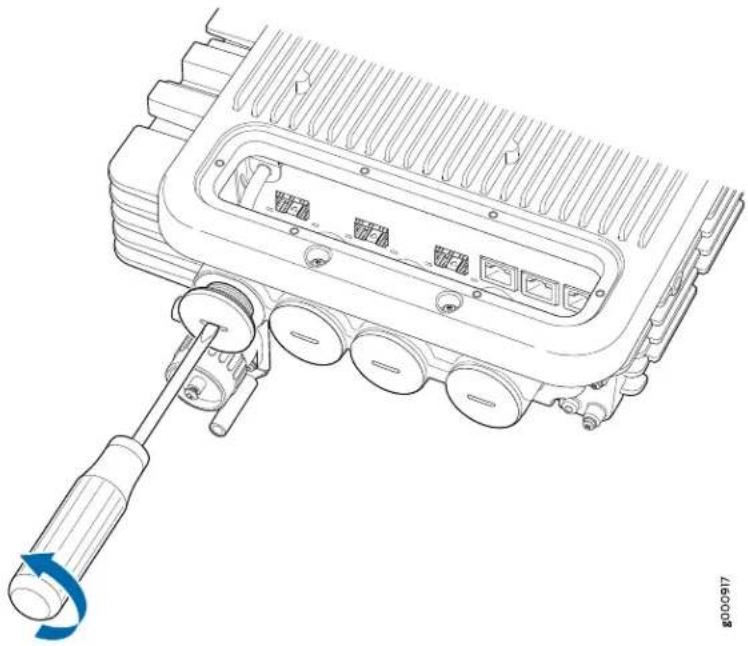
natural_image
Technical line drawing of an automotive electrical connector with a wrench and circular component (no text or symbols)
WARNING: Ensure that you have the weather seal caps on the cable inlet ports that are not in use. Failing to do so might allow water and dust to enter the router, resulting in router failure.
- Unscrew and remove the corresponding cable connector unit from the cable inlet port. See Figure 47 on page 124.
The cable connector unit consists of three components—the outer connector enclosure, the connector screw, and the cable seal. The front end of the outer cable connector enclosure is from where the interface cable enters the router, and the rear end with screw thread connects directly to the chassis cable port on the router. The connector screw houses a rubber cable seal, and screws fit tightly in the cable connector enclosure. The cable seal is a small cylindrical rubber structure with grooves or holes for the cables to pass through. The cable seal sits tightly in the connector screw and prevents water and dust particles from entering the router.

NOTE: The cable seal with single groove must be used for the SFP cables, and that with three grooves must be used for the RJ-45 cables.
Figure 47: Removing the ACX500 Outdoor Router Cable Connector Unit
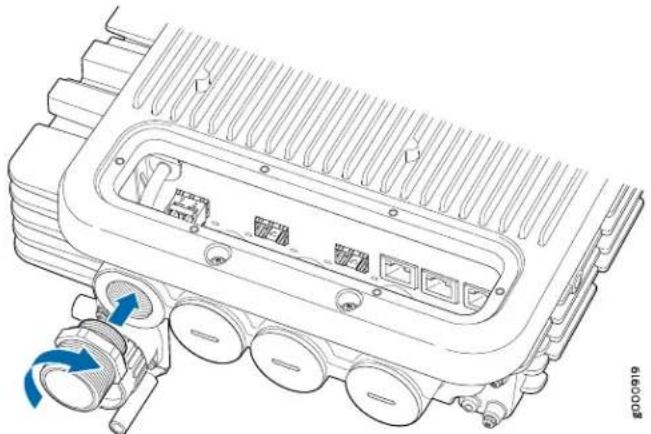
natural_image
Technical line drawing of an internal combustion engine housing with valve ports and airflow indicators (no text or symbols)- Carefully align the transceiver with the cable inlet hole of the SFP port where you want to insert the interface cable, and slide the transceiver until the connector is seated in the corresponding port. See Figure 48 on page 125.
Figure 48: Installing a Transceiver on the ACX500 Outdoor Router

natural_image
Technical diagram of an internal combustion engine housing with labeled components (no text or symbols present)1—Transceiver
To install a transceiver:
a. Take each transceiver to be installed out of its electrostatic bag, and identify the slot on the component where it will be installed.
b. Verify that each transceiver is covered by a rubber safety cap. If it is not, cover the transceiver with a safety cap.
c. Carefully align the transceiver with the slots in the component. The connectors must face the component.
d. Slide the transceiver until the connector is seated in the component slot. If you are unable to fully insert the transceiver, make sure that the connector is facing the right way.
e. Close the ejector handle of the transceiver.
-
Remove the cable seal from the cable connector unit (also known as cable gland unit) by loosening the connector screw and pushing the cable seal out. See Figure 50 on page 127. Keep the cable seal and the cable connector unit for later use.
-
Pass the interface cable through the front end of the outer cable connector enclosure.

NOTE: Ensure that you use an outdoor installation rated and IP65-compliant waterproof fiber-optic cable with an outer diameter of 10 mm for the SFP ports, and that with an outer diameter of 6.5 mm for the RJ-45 ports for the ACX500 outdoor routers.
- Slide the interface cable up to at least 2 in. (5.08 cm) into the cable seal groove. See Figure 49 on page 126.
The groove in the cable seal has slits that help push the cables easily into the groove.

NOTE:
- The cable seal with single groove must be used for the SFP interface cables, and the one with three grooves must be used for the RJ-45 interface cables.
- Ensure that each groove on the rubber cable seal accommodates only one cable through it.
- Leave at least 2 in. (5.08 cm) of interface cable for connecting it to the transceiver.
Figure 49: Installing the ACX500 Outdoor Router Cable Seal on the Interface Cable

3-1—Rubber cable seal with grooveInterface cable
4-2-Hole-plugsOuter cover of cable seal
- Push back the cable seal enclosing the interface cable back into the cable connector unit. See Figure 50 on page 127.
The connector enclosure connects directly to the router's cable inlet port. The cable seal wraps the interface cable and, along with the connector screw on top of it, makes the whole unit watertight and dustproof.
Figure 50: ACX500 Outdoor Router Cable Connector Unit

| 3-1-Cable sealConnector enclosure | |
| 4-2-Connector screwInterface SFP cable |
-
Push the connector screw back on top of the cable seal until the whole unit fits tightly.
-
Tighten the connector screw's thread end along with the cable seal inside it back into the connector enclosure port on the router. See Figure 51 on page 128.
Pull the cable with a torque of 16 lb-in. (1.8 Nm) to ensure that the cable sits tightly inside the cable connector unit. Also, visually examine the cable and the groove to ensure that there is no gap left, and that the cable sits properly in the groove.
Figure 51: Installing the ACX500 Outdoor Router Connector Screw

natural_image
Technical line drawing of an automotive engine housing with internal components and a blue directional arrow indicating rotation (no text or symbols)-
Repeat steps 3 through step 10 for the remaining interface cables, as required.
-
Insert the interface cables into the respective transceivers. See "Replacing a Fiber-Optic Cable" on page 162. Use the interface port chamber to snap in the SFP cable into the transceiver.
-
Verify that the status LEDs on the front panel indicate that the transceiver is functioning correctly. For more information about the component LEDs, see "LEDs on ACX500 Routers" on page 41.
-
Replace the metal cover of the interface port chamber back to its original place, and secure it with the six screws that were removed in step 1.

NOTE: Ensure that the metal cover sits tightly on top of the router. Failing to do so might allow dust and water to enter the router.
The Gigabit Ethernet SFP ports are now weatherproof and are ready to use.
Weatherproofing the Interface Ports—Gigabit Ethernet RJ-45
To access and weatherproof the Gigabit Ethernet RJ-45 interface ports and cables:
- Unscrew and remove the six screws from the metal cover on top of the router that covers the interface port chamber. Keep the screws for later use.
As shown in Figure 45 on page 122 from left to right, the first three cable connector inlets are for the three Gigabit Ethernet ports supporting SFP transceivers. The fourth inlet is for the cables for the three Gigabit Ethernet RJ-45 ports.
- Remove the weather seal cap from the cable inlet port on the router by using a slotted screwdriver. See Figure 52 on page 129. Keep the weather seal cap in a safe place for future use.
Weather seal caps prevent dust and water from entering the router when the router or the interface port is not in use.
Figure 52: Removing the ACX500 Outdoor Router Weather Seal Cap

natural_image
Technical line drawing of a mechanical device with a screwdriver inserted, showing internal components and a blue circular arrow indicating rotation (no text or symbols present)
WARNING: Ensure that you have the weather seal caps on the cable inlet ports that are not in use. Failing to do so might allow water and dust to enter the router resulting in router failure.
- Unscrew and remove the corresponding cable connector unit from the cable inlet port. see Figure 53 on page 130.
The cable connector unit consists of three components—the outer connector enclosure, the connector screw, and the cable seal. The front end of the outer cable connector enclosure is from where the interface cable enters the router, and the rear end with screw thread connects directly to the chassis cable port on the router. The connector screw houses the rubber cable seal, and the screw fits tightly in the cable connector enclosure. The cable seal is a small cylindrical rubber structure with grooves or holes for the cables to pass through. The cable seal sits tightly in the connector screw and prevents water and dust particles from entering the router.

NOTE: The cable seal with single groove must be used for the SFP cables, and that with three grooves must be used for the RJ-45 cables.
Figure 53: Removing the Cable Connector Unit

natural_image
Technical line drawing of a mechanical component with internal channels and connectors (no text or symbols)-
Remove the cable seal from the cable connector unit (also known as cable gland unit) by loosening the connector screw and pushing the cable seal out. See Figure 54 on page 131. Keep the cable seal and the cable connector unit for later use.
-
Pass the interface cable through the front end of the outer cable connector enclosure.

NOTE: Ensure that you use an outdoor installation rated and IP65-compliant waterproof fiber-optic cable with an outer diameter of 10 mm for the SFP ports, and that with an outer diameter of 6.5 mm for the RJ-45 ports for the ACX500 outdoor routers.
Figure 54: Cable Connector Unit

| 3-1-Cable sealConnector enclosure | |
| 4-2-Connector screwInterface RJ-45 cable |
- Slide the interface cable up to at least 2 in. (5 cm). into the cable seal groove. See Figure 55 on page 132.
The grooves in the cable seal have slits that help push the cables easily into the groove

NOTE:
- The cable seal with single groove must be used for the SFP interface cables, and the one with three grooves must be used for the RJ-45 interface cables.
- Ensure that each groove on the rubber cable seal accommodates only one cable through it.
- Leave at least 2 in. (5 cm) of interface cable for connecting it to the transceiver.
- Leave in place the hole-plugs for the unused cable seal groove holes.
Figure 55: Installing the ACX500 Outdoor Router Cable Seal on the Interface Cable

| 3-1- Rubber cable seal with groovesInterface cable | |
| 4-2- Hole-plugsOuter cover of cable seal |
- Repeat steps 5 through step 6 for the remaining RJ-45 interface cables, as required. Leave in place the hole-plugs for the unused cable seal groove holes.
- Push back the cable seal enclosing the interface cable back into the cable connector unit.
- Provide enough cable slack to reach the connector.
- Tighten the connector screw's thread end along with the cable seal inside it back into the connector enclosure port on the router. See Figure 56 on page 132.
Figure 56: Installing the ACX500 Outdoor Router Connector Screw

natural_image
Technical line drawing of an internal combustion engine component with a blue valve inserted (no text or symbols)- Insert the respective interface cable into the port. Use the interface port chamber to snap in the RJ-45 cable into the RJ-45 port.
- Verify that the status LEDs on the front panel indicate that the transceiver is functioning correctly. For more information about the component LEDs, see "LEDs on ACX500 Routers" on page 41.
- Replace the metal cover of the interface port chamber back to its original place, and secure it with the six screws that were removed in step 1.

NOTE: Ensure that the metal cover sits tightly on top of the router. Failing to do so might allow dust and water to enter the router.
The Gigabit Ethernet RJ-45 ports are now weatherproof and are now ready to use.
Accessing and Weatherproofing the Management Ports
In the ACX500 outdoor router, all the management ports (console, ToD, management, alarm, external clocking 1 PPS, and USB ports) are located in a small chamber on the front bottom of the router. You can access the management ports to access the router, to perform tasks such as monitoring, upgrading, and so on. The metal cover locks and seals the chamber from external environmental factors. See Figure 45 on page 122.

NOTE: You need access to the management components only when there is a need to perform any monitoring or upgradation task on the router. Other than that, the management port chamber must always be kept closed and sealed to protect the internal ports from dust and water, and to meet the IP65 requirement.
To access and weatherproof the management ports:
- Unscrew and remove the seven screws from the metal cover on the front of the router that covers the management port chamber. Keep the screws and the cover for later use.
- Perform the management task as required. See "Connecting ACX500 Routers to Management Devices" on page 151.
- Replace the metal cover of the management port chamber back to its original place, and secure it with the seven screws that were removed in step 1.

NOTE: Ensure that the metal cover sits tightly on top of the router. Failing to do so might allow dust and water to enter the router.
Related Documentation
•Front Panel of an ACX500 Outdoor Router on page 35
•Installing and Connecting an ACX500 Outdoor Router Overview on page 102
CHAPTER 13
Connecting the ACX500 to Ground
- Connecting the ACX500 Router to Earth Ground on page 135
Connecting the ACX500 Router to Earth Ground
You must ground both the AC-powered and the DC-powered routers before connecting them to power. Failing to ground the router properly might result in shock hazard.
To ground the router, you need the following tools:
• Phillips (+) screwdriver, number 2
• Electrostatic discharge (ESD) grounding wrist strap
- Two 0.5-in. long stainless steel SS 316 SAE 10-32 screws, and flat washers (not provided)
- Grounding lug, Panduit LCD6-10A-L or equivalent for the ACX500 indoor router, and Panduit LCCF6-14A-L for the ACX500 outdoor router (not provided)
- Grounding cable, minimum 6 AWG (13.3) m ^20 ° C wire for both the ACX500 indoor and outdoor routers (not provided)
- Corrosion-preventing compound for the ACX500 outdoor router, such as NO-OX-ID (not provided)

WARNING: The ACX500 outdoor router has a provision for connecting a two-hole grounding lug (Panduit LCCF6-14A-L). Ensure that the router is permanently grounded with 6-AWG copper wire with this specified two-hole lug.
You ground the router by connecting a grounding cable to earth ground and then attaching it to the chassis grounding points. To ground the router:
- Verify that a licensed electrician has attached the cable lug provided with the router to the grounding cable.
- Attach an electrostatic discharge (ESD) grounding strap to your bare wrist, and connect the strap to an approved site ESD grounding point. See the instructions for your site.
- Ensure that all grounding surfaces are clean and brought to a bright finish before grounding connections are made.
- Connect the grounding cable to a proper earth ground.
- Detach the ESD grounding strap from the site ESD grounding point.
- Attach an ESD grounding strap to your bare wrist and connect the strap to one of the ESD points on the chassis.
- Place the grounding cable lug over the grounding points on the front of the chassis (see Figure 57 on page 136 and Figure 58 on page 136).
Figure 57: Grounding Point Location on the ACX500 Indoor Router

1— Grounding terminals
Figure 58: Grounding Point Location on the ACX500 Outdoor Router
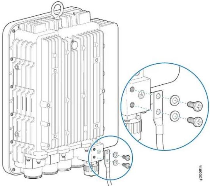
natural_image
Technical line drawing of an electronic device housing with internal components and a close-up inset showing pin connections (no text or symbols)
NOTE:
- In the ACX500 indoor routers, the grounding points are located on the front left of the router.
- In the ACX500 outdoor routers, the grounding points are located just below the power inlet port.
- The location of the grounding points on the ACX500 routers is the same for both the AC and the DC variants.
For the ACX500 outdoor routers, perform the following additional steps as rust-preventative and corrosion-preventative measure:
a. Clean both the mating surfaces (the grounding cable lug and the ACX500 outdoor router grounding terminals).
b. Apply a thin film (0.04 in. or 1 mm) of corrosion-preventing compound, such as NO-OX-ID, on the ACX500 outdoor router's grounding terminals.
c. Press the lug onto the conductive surface unit in order to force out the excess corrosion-preventing compound.
- Secure the grounding cable lug with the washers and screws. The holes are sized for SAE 10-32 screws. Apply 4 lb-in. (0.49 Nm) of torque to each screw. Do not overtighten the screw (use a number 2 Phillips screwdriver). See Figure 59 on page 137 and Figure 58 on page 136.
Figure 59: Grounding Points on the ACX500 Indoor Router
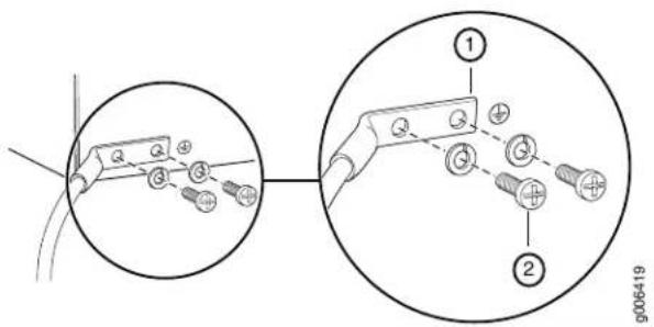
2-1- SAE 10-32 screws and washersGrounding lug

CAUTION: Ensure that each grounding lug sits flush against the surface of the grounding points as you are tightening the screws. Ensure that each screw is properly threaded into the grounding points. Applying installation torque to the screw when improperly threaded can damage the terminal.

CAUTION: The maximum torque rating of the grounding screws on the router is 4 lb-in. (0.49 Nm). The grounding screws can be damaged if excessive torque is applied. Use only a torque-controlled driver to tighten
screws. Use an appropriately sized driver, with a maximum torque capacity of 5 lb-in. (0.56 Nm) or less. Ensure that the driver is undamaged and properly calibrated and that you have been trained in its use. You might want to use a driver that is designed to prevent overtorque when the preset torque level is achieved.
- Verify that the grounding cabling is correct, and verify that it does not touch or block access to router components, and that it does not drape where people could trip on it.
Related Documentation
•Installing and Connecting an ACX500 Indoor Router Overview on page 101
•Installing and Connecting an ACX500 Outdoor Router Overview on page 102
•Site Preparation Checklist for ACX500 Routers on page 53
•Preventing Electrostatic Discharge Damage to an ACX500 Router on page 196
CHAPTER 14
Providing Power to the ACX500
- Connecting an AC Power Cord to the ACX500 Indoor Router on page 139
- Connecting DC Power Cables to the ACX500 Indoor Router on page 140
- Connecting an AC Power Cord to the ACX500 Outdoor Router on page 142
- Connecting a DC Power Cord to the ACX500 Outdoor Router on page 146
Connecting an AC Power Cord to the ACX500 Indoor Router
To connect AC power to the router, you need the following tools:
• Electrostatic discharge (ESD) grounding wrist strap
• AC power cord (not provided)

NOTE: Power cord for the ACX500 indoor routers are not shipped with the router. You need to purchase the power cord separately.
To connect AC power to the router:
- Locate the power cord, which should have a plug appropriate for your geographical location. See the "ACX500 Router AC Power Cord Specifications" on page 82.
- Attach an ESD grounding strap to your bare wrist and connect the strap to one of the ESD points on the chassis.
- Insert the appliance coupler end of the power cord into the appliance inlet on the power supply.
- Insert the power cord plug into an external AC power source receptacle.

NOTE: We recommend that you use a dedicated customer-site circuit breaker rated for 20 A (100 VAC) or 16 A (240 VAC), or as required by local code. Doing so enables you to operate the router in any configuration without upgrading the power infrastructure.
-
Verify that the power cord does not block the air exhaust and access to router components, or drape where people could trip on it.
-
Observe the system LED on the router. If an AC power supply is functioning normally, the system LED lights green steadily.
If the system LED is not lit, the power supply is not functioning normally. Repeat the cabling procedures.
Figure 60: Connecting AC Power to the Router

Related Documentation
ACX500 AC Power Specifications on page 81.
- ACX500 AC Power Electrical Safety Guidelines and Warnings on page 224
•ACX500 General Electrical Safety Guidelines on page 219
Connecting DC Power Cables to the ACX500 Indoor Router
To connect DC power to the router, you need the following tools:
• Phillips (+) screwdriver, number 2
• Electrostatic discharge (ESD) grounding wrist strap
• M3 screws and flat washers
- DC power source cables, minimum 14 AWG or as required by local code (not provided)
- Ring lugs, Molex 190700067 or equivalent (not provided)

NOTE: Power cables for the ACX500 indoor routers are not shipped with the routers. You need to purchase the power cord separately.
The DC power supply has four terminals on the front panel, covered by a clear plastic cover.

WARNING: You must ground the router before connecting the DC power cables.
To connect the power cables:
-
Switch off the dedicated customer-site circuit breakers. Ensure that the voltage across the DC power source cable leads is 0 V and that there is no chance that the cable leads might become active during installation.
-
Remove the clear plastic cover protecting the terminal on the faceplate.
-
Verify that the DC power cables are correctly labeled before making connections to the power supply. In a typical power distribution scheme where the return is connected to chassis ground at the battery plant, you can use a multimeter to verify the resistance of the DC cables to chassis ground:
Locate the power cables, which should have a plug appropriate for your geographical location. See the "ACX500 DC Power Specifications" on page 84.
For -48V and -60V:
a. The cable with very large resistance (indicating an open circuit) to chassis ground is the DC input cable (-).
b. The cable with very low resistance (indicating a closed circuit) to chassis ground is the return cable (+).
For +24V:
a. The cable with very low resistance (indicating a closed circuit) to chassis ground is the return cable (-).
b. The cable with very large resistance (indicating an open circuit) to chassis ground is DC input cable (+).
-
Remove the screws and flat washers from the terminals.
-
Secure each power cable lug to the terminal with the flat washers and screw (see Figure 61 on page 142). Apply between 8 lb-in. (0.9 Nm) and 9 lb-in. (1 Nm) of torque to each screw. Do not overtighten the screw. (Use a number 2 Phillips screwdriver.)
a. Secure the positive DC source power cable lug to the return (+) terminal.
b. Secure the negative DC source power cable lug to the input (−) terminal.

CAUTION: Ensure that each power cable lugseatsflush against the surface of the terminal block as you are tightening the screws. Ensure that each screw is properly threaded into the terminal. Applying installation torque to the screw when improperly threaded might result in damage to the terminal.

CAUTION: The maximum torque rating of the terminal screws on the DC power supply is 9 lb-in. (1 Nm). The terminal screws might be damaged if excessive torque is applied. Use only a torque-controlled driver to tighten screws on the DC power supply terminals. Use an appropriately sized
driver, with a maximum torque capacity of 9 lb-in. (1 Nm) or less. Ensure that the driver is undamaged and properly calibrated and that you have been trained in its use. You might want to use a driver that is designed to prevent overtorque when the preset torque level is achieved.
- Replace the clear plastic cover over the terminals on the faceplate.
- Attach an electrostatic discharge (ESD) grounding strap to your bare wrist, and connect the strap to an approved site ESD grounding point. See the instructions for your site.
- Connect each DC power cable to the appropriate external DC power source.

NOTE: For information about connecting to external DC power sources, see the instructions for your site.
- Switch on the external circuit breakers to provide voltage to the DC power source cable leads. Observe the system LED on the front of the router. If the DC power cable is correctly installed and functioning normally, the system LED lights green steadily. If the status LED indicates that the power supply is not functioning normally, repeat the installation and cabling procedures.
Figure 61: Connecting DC Power to the Router

natural_image
Diagram of a Juniper industrial device with connected cables and a connector (no text or symbols visible)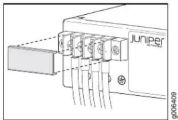
Related Documentation
ACX500 DC Power Specifications on page 84.
•ACX500 DC Power Electrical Safety Guidelines on page 225
•ACX500 General Electrical Safety Guidelines on page 219
Connecting an AC Power Cord to the ACX500 Outdoor Router

NOTE: The information provided in this topic is applicable for both the ACX500 outdoor router variants—ACX500 outdoor router and ACX500 outdoor router with PoE.
To connect AC power to the router, you need the following tools:
- Electrostatic discharge (ESD) grounding wrist strap
- AC power cord for the ACX500 outdoor router (not provided, must be purchased separately)

NOTE: Use the power cord that is purchased from Juniper Networks, and is compatible with the ACX500 outdoor router. Using a power cord other than that is provided by Juniper Networks with the router can damage the power terminal. These power cords are specifically designed to be used only with the specified ACX500 outdoor routers.

WARNING: You must ground the router before connecting the power cables.

NOTE: For disconnecting power to the router, first remove or switch off the power to the power cord by opening the circuit breaker or suitable service disconnect at the AC disconnect box or power distribution unit (PDU). Then rotate the power cord connector ring to disconnect the power cord from the router connector. Doing this ensures that the power cord is safe to handle.
To connect AC power to the router:
- Attach an ESD grounding strap to your bare wrist and connect the strap to one of the ESD points on the chassis.
- Locate the power cord that is compatible with the ACX500 outdoor router.
Power cords for the ACX500 outdoor routers are not shipped with the router. The power cords are specifically designed to be used only with the specified ACX500 outdoor routers. The unique design of these power cords help to protect the power terminal from the external environmental factors, such as water and dust.
- Remove the screw cover cap protecting the power terminal on the faceplate.
Figure 62 on page 144 shows the location of the power terminal.
Figure 62: Power Terminal Location on the ACX500 Outdoor Router

| Interface port chamber with weather seal cover | 1—Management port chamber with weather seal cover |
| 2—Cable connector ports with weather seal cap | 4—Power port with weather seal cap |
- Power off the AC power source.

NOTE: Ensure that the power source for the ACX500 outdoor router is off before connecting or disconnecting the power cord wires from the power source.
- Insert the appliance coupler terminal end of the power cord into the appliance inlet on the power source. Ensure that the power cord terminal is connected properly.
One end of the AC power cord for the ACX500 outdoor router has the AC power plug (see Figure 64 on page 145) that connects to the router, and the other end has three power cord wires (see Figure 63 on page 144) that are connected to the power source.
Figure 63: AC Power Cord Wires That Connect to the Power Source


WARNING: Ensure that the line (L), neutral (N), and ground (G) AC power cord wires are correctly connected to the respective branch circuit or power source that powers the ACX500 outdoor router. Failing to do so might result in damaging the router. The AC power cord has L, N, and G labels for reference and correct connection to AC mains terminals.
- Insert the AC power cord plug to the power terminal on the router. Ensure that the power plug sits tight. See Figure 64 on page 145.
Figure 64: Connecting AC Power Plug to the Router

natural_image
Mechanical assembly diagram showing a valve inserted into a housing with a blue arrow indicating rotation (no text or symbols present)
NOTE: An AC-powered router need to connect with the outdoor AC power cord that is supported with the router. Each power source must be connected to a dedicated AC power feed and a dedicated customer-site circuit breaker. We recommend that you use a dedicated customer-site circuit breaker rated of 20 A (100 VAC) or 16 A (240 VAC), or as required by local electrical code.
- Tighten the power cord plug screw.
The power cord plug screw prevents water and dust from entering the terminal.
-
Verify that the power cabling is correct, that the power cables or cords do not touch or block access to router components, and that they do not drape where people could trip on them.
-
Power on the AC power source to the router.
-
Observe the system LED on the router. If an AC power source is functioning normally, the system LED lights green steadily.
If the system LED is not lit, the power source is not functioning normally. Repeat the cabling procedures.

WARNING: The AC power wiring terminals where the wires join the AC power source must be protected from water and other particles. Use a certified waterproof enclosure for the AC power wires.
WARNING: To meet EN/IEC60950-22 (Clause 4.2) requirements, ensure that additional protection is provided external to the router to reducetransient voltage surges (Overvoltage Category IV to Overvoltage Category II) at the AC power input of the router. The overvoltage and fault-current protection components used to achieve this protection must comply with the IEC 61643 series of standards. Use alternative components to meet CAN/CSA-C22.2 No. 60950-22-07/UL60950-22 requirements for additional protection. The components you use for additional protection may comply with ANSI/IEEE C62.11, CSACertification Notice No. 516, CSA C22.2 No. 1, or UL 1449. Suitability of the components for the application must be determined for the intended installation. For example, some devices are suitable for installation on the load side of the service entrance only, and some are suitable for use with cord-connected equipment only.
Connecting a DC Power Cord to the ACX500 Outdoor Router

NOTE: The information provided in this topic is applicable for both the ACX500 outdoor router variants—ACX500 outdoor router and ACX500 outdoor router with PoE.
To connect DC power to the router, you need the following tools:
• Electrostatic discharge (ESD) grounding wrist strap
- DC power cord for the ACX500 outdoor router (not provided, must be purchased separately)

NOTE: Use the power cord that is purchased from Juniper Networks, and which is compatible with the ACX500 outdoor router. Using a power cord other than that is provided by Juniper Networks with the router can damage the power terminal. The nominal rating of the DC powersource are +24 VDC, -48 VDC, and -60 VDC. These power cords are specifically designed to be used only with the specified ACX500 outdoor routers.

WARNING: You must ground the router before connecting the power cords.

NOTE: Ensure that the DC power source to the equipment meet requirement of SELV power source as per IEC /EN/UL 60950-1. This SELV power source must be electrically isolated from AC power source.
To connect DC power to the router:
- Attach an ESD grounding strap to your bare wrist and connect the strap to one of the ESD points on the chassis.
- Locate the power cord that is compatible with the ACX500 outdoor router.
Power cords for the ACX500 outdoor routers are not shipped with the router. The power cords are specifically designed to be used only with the specified ACX500 outdoor routers. The unique design of these power cords help to protect the power terminal from the external environmental factors, such as water and dust.
- Remove the screw cover cap protecting the power terminal on the faceplate.
Figure 65 on page 148 shows the location of the power terminal.
Figure 65: Power Terminal Location on the ACX500 Outdoor Router

| 3-1- Management port coverInterface port cover | |
| 4-2- Power port with dust coverCable connector ports wit |
- Insert the appliance coupler terminal end of the power cord into the appliance inlet on the power supply. Ensure that the power cord terminal is connected properly.
- Insert the DC power cord plug to the power terminal on the router. Ensure that the power plug sits tight. See Figure 66 on page 148.
Figure 66: Connecting DC Power to the Router
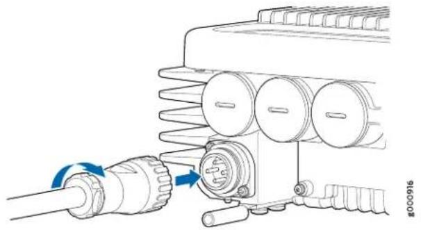
natural_image
Mechanical assembly diagram showing a pipe connection to a motor with spring components (no text or symbols)1— Power terminal

NOTE: A DC-powered router needs to be connected with the outdoor DC power cord that is purchased from Juniper Networks, and which is compatible with the ACX500 outdoor router. To supply sufficient power, the DC input wiring on the facility DC source is capable of supplying at least 5 A @-48 VDC per input for each power supply. We recommend that the 48-VDC facility DC source should be equipped with a circuit breaker rated at 5 A @-48 VDC minimum, or as required by local code.
For other nominal input voltages such as 24VDC, -60 VDC, were recommend that the circuit breaker rating be appropriately sized or rated, and as required by local code.
- Tighten the power cord plug screw.
The power cord plug screw prevents water and dust from entering the terminal.
-
Verify that the power cabling is correct, that the power cables do not touch or block access to router components, and that they do not drape where people could trip on them.
-
Observe the system LED on the router. If an DC power supply is functioning normally, the system LED lights green steadily.
If the system LED is not lit, the power supply is not functioning normally. Repeat the cabling procedures.
Related Documentation
•ACX500 Power Overview on page 49
•ACX500 DC Power Electrical Safety Guidelines on page 225
•ACX500 General Electrical Safety Guidelines on page 219
CHAPTER 15
Connecting the ACX500 to External Devices
- Connecting ACX500 Routers to Management Devices on page 151
- Connecting the ACX500 Router to an External Alarm-Reporting Device on page 153
- Connecting the ACX500 Router to External Clocking Devices on page 154
Connecting ACX500 Routers to Management Devices
To connect external devices and cables to the router, you need the following tools:
- RJ-45 Ethernet cable and RJ-45 to DB-9 serial port adapter (provided)
- Management host, such as a PC, with an Ethernet port (not provided)

NOTE: Ensure that you use a waterproof fiber-optic cable with an outer diameter of 10 mm for the SFP ports, and that with an outer diameter of 6.5 mm for the RJ-45 ports.
For the ACX500 outdoor router, see “Weatherproofing the ACX500 Outdoor Router” on page 121 topic to know how to access, secure, and weatherproof the router ports. See “Front Panel of an ACX500 Outdoor Router” on page 35 to know more about the ports that are available under the management port cover on the ACX500 outdoor router.

NOTE: When accessing the management ports of the ACX500 outdoor router, ensure to weatherproof the port units by securing back the interface port cover.
- Connecting the Router to a Network for Out-of-Band Management on page 152
- Connecting the Router to a Management Console on page 152
Connecting the Router to a Network for Out-of-Band Management
To connect to the MGMT port on the ACX500 router:
- Turn off the power to the management device.
- Plug one end of the Ethernet cable into the MGMT port on the router. (Figure 67 on page 152 shows the connector. Figure 68 on page 152 shows the port.)
- Plug the other end of the cable into the network device.
Figure 67: Ethernet Cable Connector

Figure 68: Ethernet Port
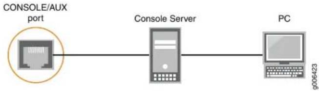
flowchart
graph LR
    A["CONSOLE/AUX port"] --> B["Console Server"]
    B --> C["PC"]
Connecting the Router to a Management Console
You can connect a console, laptop, or modem by connecting a serial cable to the port on the front panel labeled MGMT. This port accepts a serial cable with an RJ-45 connector, which is provided with the router.
To connect a management console:
- Turn off the power to the console.
-
Plug the RJ-45 end of the serial cable into the MGMT port on the front panel (Figure 69 on page 153 shows the connector. Figure 70 on page 153 shows the ports.)
-
Plug the female DB-9 end into the device's serial port.

NOTE:
For console devices, configure the serial port to the following values:
- Bits per second—9600
- Data bits—8
- Parity—None
- Stop bits—1
- Flow control—None
Figure 69: Routing Engine Console Cable Connector
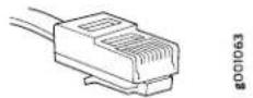
Figure 70: Console Connections

flowchart
graph LR
    A["CONSOLE/AUX port"] --> B["Console Server"]
    B --> C["PC"]
Related Documentation
Installing and Connecting an ACX500 Indoor Router Overview on page 101.
•General Site Guidelines for ACX Series Routers on page 69
• Management Port Connector Pinout Information for ACX500 Routers on page 77
•Performing Initial Software Configuration for the ACX500 Router on page 155
•Front Panel of an ACX500 Outdoor Router on page 35
•Front Panel of an ACX500 Indoor Router on page 33
Connecting the ACX500 Router to an External Alarm-Reporting Device
To connect the router to external alarm-reporting devices, attach wires to the ALARM relay contacts on the front panel of the router. A system condition that triggers the red or yellow alarm on the router also activates the corresponding alarm relay contact.
The terminal blocks that plug into the alarm relay contacts are supplied with the router. They accept wire of any gauge between 20 AWG and 14 AWG (0.52 and 2.08 mm which is not provided. Use the gauge of wire appropriate for the external device you are connecting.
For the ACX500 outdoor router, see "Weatherproofing the ACX500 Outdoor Router" on page 121 topic to know how to access, secure, and weatherproof the router ports.
To connect an external device to an alarm relay contact:
- Prepare the required length of wire with gauge between 8 AWG and 14 AWG (0.08 and 2.08 mm
- Attach an electrostatic discharge (ESD) grounding strap to your bare wrist, and connect the strap to one of the ESD points on the chassis.
-
While the terminal block is not plugged into the relay contact, use a 2.5 mm flat-blade screwdriver to loosen the small screws on its side. With the small screws on its side facing left, insert wires into the slots in the front of the block based on the wiring for the external device. Tighten the screws to secure the wire.
-
Orient the terminal block according to the labels to the left of the appropriate relay contact (NC means "normally closed", C means "common," and NO means "normally open").
- Plug the terminal block into the relay contact and use a 2.5 mm flat-blade screwdriver to tighten the screws on the face of the block.
- Attach the other end of the wires to the external device.
If you are attaching a reporting device for the other kind of alarm, repeat the procedure.
Related Documentation
Alarm Contact Port on ACX500 Routers on page 39.
•Alarm Contact Port Pinouts for ACX500 Routers on page 75
•Verifying Active Alarms on page 177
•Troubleshooting Resources for ACX500 Routers on page 175
Connecting the ACX500 Router to External Clocking Devices
The ACX500 routers support external clock synchronization for Synchronous Ethernet, and external inputs.
- Connecting 1 PPS Timing Devices to the Router on page 154
Connecting 1 PPS Timing Devices to the Router
The two SubMiniature B (SMB, 1 PPS input and 1 PPS output) connectors on the front panel of the router connect to external clock signal sources.
To connect the SMB coaxial cable to the external clocking input port:
- Connect one end of the SMB coaxial cable to the 1 PPS SMB connector on the router.
- Connect the other end of the SMB coaxial cable to the 1 PPS source network equipment.
CHAPTER 16
Configuring Junos OS on ACX500 Route
- Performing Initial Software Configuration for the ACX500 Router on page 155
Performing Initial Software Configuration for the ACX500 Router
The ACX500 routers are shipped with Junos OS preinstalled and ready to be configured when the router is powered on. One 4-GB internal NAND flash memory device is divided into two partitions (da0s1 and da0s2). One partition is marked as the active partition, and the other partition functions as an alternate partition. The NAND flash device acts as the hard drive. One USB port on the front panel accepts a USB storage device (usb0) that can also function as an alternate boot device.
When the router boots, it first attempts to start the image on the USB flash memory device. If a USB flash memory device is not inserted into the router or the attempt otherwise fails, the router next tries the active partition on the NAND flash device, and then tries the alternate partition on the NAND flash device.
You configure the router by issuing Junos OS command-line interface (CLI) commands, either on a console device attached to the CONSOLE port on the front panel, or over a telnet connection to a network connected to the Routing Engine MGMT port on the front panel.
Gather the following information before configuring the router:
- Name that the router will use on the network
- Domain name that the router will use
- IP address and prefix length information for the Ethernet interface
• IP address of a default router
• IP address of a DNS server - Password for the root user
This procedure connects the router to the network but does not enable it to forward traffic. For complete information about enabling the router to forward traffic, including examples, see the Junos OS configuration guides.
To configure the software:
- Verify that the router is powered on.
-
Log in as the "root" user. There is no password.
-
Start the CLI.
root# cli
root@>
- Enter configuration mode.
cli> configure
[edit]
root@#
- Configure the name of the router. If the name includes spaces, enclose the name in quotation marks (“ ”).
[edit]
root@# set system host-name host-name
- Create a management console user account.
[edit]
root@# set system login user user-name authentication plain-text-password
New password: password
Retype new password: password
- Set the user account class to super-user.
[edit]
root@# set system login user user-name class super-user
- Configure the router's domain name.
[edit]
root@# set system domain-name domain-name
- Configure the IP address and prefix length for the router's Ethernet interface.
[edit]
root@# set interfaces fxp0 unit 0 family inet address address/prefix-length
- Configure the IP address of a backup router, which is used only while the routing protocol is not running.
[edit]
root@# set system backup-router address
- Configure the IP address of a DNS server.
[edit]
root@# set system name-server address
- Set the root authentication password by entering either a clear-text password, an encrypted password, or an SSH public key string (DSA or RSA).
[edit]
root@# set system root-authentication plain-text-password
New password: password
Retype new password: password

or

[edit]
root@# set system root-authentication encrypted-password encrypted-password

or

[edit]
root@# set system root-authentication ssh-dsa public-key

or

[edit]
root@# set system root-authentication ssh-rsa public-key
- (Optional) Configure the static routes to remote subnets with access to the management port. Access to the management port is limited to the local subnet. To access the management port from a remote subnet, you need to add a static route to that subnet within the routing table. For more information about static routes, see the Junos OS Administration Library for Routing Devices.
[edit]
root@# set routing-options static route remote-subnet next-hop destination-IP retain no-readvertise
- Configure the telnet service at the [edit system services] hierarchy level.
[edit]
root@# set system services telnet
- (Optional) Display the configuration to verify that it is correct.
[edit]
root@# show
system {
    host-name host-name;
    domain-name domain-name;
    backup-router address;
    root-authentication {
    authentication-method (password | public-key);
    }
    name-server {
    address;
    }
}
interfaces {
    fxp0 {
    unit 0 {
    family inet {
    address address/prefix-length;
    }
    }
    }
}
- Commit the configuration to activate it on the router.
[edit]
root@# commit
- (Optional) Configure additional properties by adding the necessary configuration statements. Then commit the changes to activate them on the router.
[edit]
root@host# commit
- When you have finished configuring the router, exit configuration mode.
[edit]
root@host# exit
root@host>
Related •ACX500 Routers Hardware and CLI Terminology Mapping on page 9 Documentation •Protocols and Applications Supported by ACX Series Routers on page 15
PART 4
Installing and Replacing Components
- Replacing Chassis Components on page 161
CHAPTER 17
Replacing Chassis Components
- Replacing a Console Cable on page 161
- Replacing a Management Ethernet Cable on page 162
- Replacing a Fiber-Optic Cable on page 162
• Replacing an SFP Transceiver on page 164
Replacing a Console Cable
- Removing a Console Cable on page 161
- Installing a Console Cable on page 161
Removing a Console Cable
To remove a serial cable connected to a console device:
- Attach an ESD grounding strap to your bare wrist and connect the strap to one of the ESD points on the chassis.
- Press the tab on the connector, and pull the connector straight out of the CONSOLE port. Figure 71 on page 161 shows the connector.
- Disconnect the cable from the console.
Figure 71: Ethernet Cable Connectors

g003781
Installing a Console Cable
The CONSOLE port on the front panel of the router accepts an RS-232 (EIA-232) serial cable with RJ-45 connectors.
To connect a cable between the router and the console device:
- Attach an ESD grounding strap to your bare wrist and connect the strap to one of the ESD points on the chassis.
-
Connect one end of the replacement cable into the CONSOLE port.
-
Plug the other end of the cable into the device's serial port.
Related Console Port Connector Pinout on ACX500 Routers on page 78. Documentation
Replacing a Management Ethernet Cable
- Removing a Management Ethernet Cable on page 162
- Installing a Management Ethernet Cable on page 162
Removing a Management Ethernet Cable
To remove a serial cable connected to a management device:
- Attach an ESD grounding strap to your bare wrist and connect the strap to one of the ESD points on the chassis.
- Press the tab on the connector, and pull the connector straight out of the MGMT port. Figure 72 on page 162 shows the connector.
- Disconnect the cable from the network device.
Figure 72: Ethernet Cable Connectors
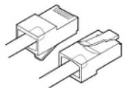
g003781
Installing a Management Ethernet Cable
To install a serial cable connected to a management device:
- Attach an ESD grounding strap to your bare wrist and connect the strap to one of the ESD points on the chassis.
- Plug one end of the replacement cable into the appropriate MGMT port.
- Plug the other end of the cable into the network device.
Related Documentation Management Port Connector Pinout Information for ACX500 Routers on page 77.
Replacing a Fiber-Optic Cable
To replace a fiber-optic cable:
- Disconnecting a Fiber-Optic Cable on page 163
- Connecting a Fiber-Optic Cable on page 163
Disconnecting a Fiber-Optic Cable
ACX Series routers have field-replaceable unit (FRU) optical transceivers to which you can connect fiber-optic cables.
Before you begin disconnecting a fiber-optic cable from an optical transceiver installed in an ACX Series router, ensure that you have taken the necessary precautions for safe handling of lasers (see "General Laser Safety Guidelines for Juniper Networks Devices" on page 209).
Ensure that you have the following parts and tools available:
• A rubber safety cap to cover the transceiver
- A rubber safety cap to cover the fiber-optic cable connector
To disconnect a fiber-optic cable from an optical transceiver installed in the router:
- Disable the port in which the transceiver is installed by issuing the following command:
[edit interfaces] user@router# set interface-namedIsable

WARNING: Do not look directly into a fiber-optic transceiver or into the ends of fiber-optic cables. Fiber-optic transceivers and fiber-optic cables connected to transceivers emit laser light that can damage your eyes.
-
Carefully unplug the fiber-optic cable connector from the transceiver.
-
Cover the transceiver with a rubber safety cap.

WARNING: Do not leave a fiber-optic transceiver uncovered except when inserting or removing a cable. The rubber safety cap keeps the port clean and prevents accidental exposure to laser light.
- Cover the fiber-optic cable connector with the rubber safety cap.
Connecting a Fiber-Optic Cable
ACX Series routers have field-replaceable unit (FRU) optical transceivers to which you can connect fiber-optic cables.
Before you begin connecting a fiber-optic cable to an optical transceiver installed in a router, ensure that you have taken the necessary precautions for safe handling of lasers (see "General Laser Safety Guidelines for Juniper Networks Devices" on page 209).
To connect a fiber-optic cable to an optical transceiver installed in an ACX Series router:

WARNING: Do not look directly into a fiber-optic transceiver or into the ends of fiber-optic cables. Fiber-optic transceiversandfiber-opticcablesconnected to transceivers emit laser light that can damage your eyes.
- If the fiber-optic cable connector is covered by a rubber safety cap, remove the cap. Save the cap.
- Remove the rubber safety cap from the optical transceiver. Save the cap.
- Insert the cable connector into the optical transceiver (see Figure 73 on page 164).
Figure 73: Connecting a Fiber-Optic Cable to an Optical Transceiver Installed in an ACX Series Router

- Secure the cables so that they are not supporting their own weight. Place excess cable out of the way in a neatly coiled loop. Placing fasteners on a loop helps cables maintain their shape.

CAUTION: Do not bend fiber-optic cables beyond their minimum bend radius. Anarc smaller than a few inches in diameter can damage the cables and cause problems that are difficult to diagnose.
Do not let fiber-optic cables hang free from the connector. Do not allow fastened loops of cables to dangle, which stresses the cables at the fastening point.
Replacing an SFP Transceiver
- Removing an SFP Transceiver on page 164
• Installing an SFP Transceiver on page 166
Removing an SFP Transceiver
Removing a transceiver does not interrupt router functioning, but the removed transceiver no longer receives or transmits data.
To remove a transceiver (see Figure 74 on page 165):
-
Have ready a replacement transceiver or a transceiver slot plug, an antistatic mat, and a rubber safety cap for the transceiver.
-
Attach an ESD grounding strap to your bare wrist and connect the strap to one of the ESD points on the chassis.
-
Label the cables connected to the transceiver so that you can reconnect them correctly later.

WARNING: Do not look directly into a fiber-optic transceiver or into the ends of fiber-optic cables. Fiber-optic transceivers and fiber-optic cable connected to a transceiver emit laser light that can damage your eyes.
-
Remove the cable connector from the transceiver.
-
Pull the ejector handle out from the transceiver to unlock the transceiver.

CAUTION: Make sure that you open the ejector handle completely until you hear it click. This action prevents damage to the transceiver.
Use needle-nose pliers to pull the ejector handle out from the transceiver.
-
Grasp the transceiver ejector handle, and pull the transceiver approximately 0.5 in. (1.3 cm) out of the router.
-
Using your fingers, grasp the body of the transceiver, and pull it the rest of the way out of the router.
Figure 74: Removing Transceivers
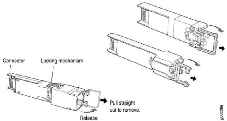
-
Place a rubber safety cap over the transceiver.
-
Place the removed transceiver on an antistatic mat or in an electrostatic bag.

CAUTION: After removing a transceiver from the chassis, wait at least 30 seconds before reinserting it or inserting a transceiver into a different slot.
Installing an SFP Transceiver
To install a transceiver:
- Attach an ESD grounding strap to your bare wrist and connect the strap to one of the ESD points on the chassis.
- Take each transceiver to be installed out of its electrostatic bag, and identify the slot on the component where it will be installed.
- Verify that each transceiver is covered by a rubber safety cap. If it is not, cover the transceiver with a safety cap.
- Carefully align the transceiver with the slots in the component. The connectors should face the component.
- Slide the transceiver until the connector is seated in the component slot. If you are unable to fully insert the transceiver, make sure the connector is facing the right way.
- Close the ejector handle of the transceiver.
- Remove the rubber safety cap from the transceiver and the end of the cable. Insert the cable into the transceiver.

WARNING: Do not look directly into a fiber-optic transceiver or into the ends of fiber-optic cables. Fiber-optic transceivers and fiber-optic cable connected to a transceiver emit laser light that can damage your eyes.
- Verify that the status LEDs on the front panel indicate that the transceiver is functioning correctly. For more information about the component LEDs, see the "LEDs on ACX500 Routers" on page 41.
Related Documentation
•Preventing Electrostatic Discharge Damage to an ACX500 Router on page 196
PART 5
Maintaining the Chassis and Component
- Maintaining Components on page 169
CHAPTER 18
Maintaining Components
• Routine Maintenance Procedures for the ACX500 Router on page 169
- Maintaining Cables That Connect to ACX500 Network Ports on page 169
- Maintaining the ACX500 Uplink Ports on page 170
Routine Maintenance Procedures for the ACX500 Router
Purpose For optimum router performance, perform preventive maintenance procedures.
Action Inspect the installation site for moisture, loose wires or cables, and excessive dust. Make sure that airflow is unobstructed around the router and into the air intake vents. •Check the status-reporting devices on the front panel—system LED.
Related Documentation Maintaining Cables That Connect to ACX500 Network Ports on page 169. •Maintaining the ACX500 Uplink Ports on page 170
Maintaining Cables That Connect to ACX500 Network Ports
Purpose For optimum router performance, verify the condition of the cables that connect to the network ports.
Action On a regular basis:
- Place excess cable out of the way. Do not allow fastened loops of cable to dangle from the connector, because this stresses the cable at the fastening point. Putting fasteners on the loops helps to maintain their shape.
- Keep the cable connections clean and free of dust and other particles, which can cause drops in the received power level. Always inspect cables, and clean them if necessary before connecting an interface.
- Label both ends of the cables to identify them.
The following guidelines apply specifically to fiber-optic cables:
- When you unplug a fiber-optic cable, always place a rubber safety plug over the transceiver on the faceplate and on the end of the cable.
- Anchor fiber-optic cables to avoid stress on the connectors. Be sure to secure fiber-optic cables so that they do not support their own weight as they hang to the floor. Never let fiber-optic cable hang free from the connector.
- Avoid bending fiber-optic cable beyond its bend radius. An arc smaller than a few inches can damage the cable and cause problems that are difficult to diagnose.
- Frequent plugging and unplugging of fiber-optic cable into and out of optical instruments can cause damage to the instruments that is expensive to repair. Instead, attach a short fiber extension to the optical equipment. Any wear and tear due to frequent plugging and unplugging is then absorbed by the short fiber extension, which is easy and inexpensive to replace.
- Keep fiber-optic cable connections clean. Small microdeposits of oil and dust in the canal of the transceiver or cable connector could cause loss of light, reducing signal power and possibly causing intermittent problems with the optical connection.
To clean the transceivers, use an appropriate fiber-cleaning device, such as RIFOCS Fiber Optic Adaptor Cleaning Wands (part number 946). Follow the directions for the cleaning kit you use.
After you clean an optical transceiver, make sure that the connector tip of the fiber-optic cable is clean. Use only an approved alcohol-free fiber-optic cable cleaning kit, such as the Opptex Cletop-S Fiber Cleaner. Follow the directions for the cleaning kit you use.
Related Documentation
Routine Maintenance Procedures for the ACX500 Router on page 169.
•Troubleshooting Resources for ACX500 Routers on page 175
•Replacing a Fiber-Optic Cable on page 162
Maintaining the ACX500 Uplink Ports
Purpose For optimum performance, verify the condition of the uplink ports.
Action On a regular basis:
- Check the port LEDs. The meaning of the LED states differs for various uplink ports. For more information, see "LEDs on ACX500 Routers" on page 41. If the router detects a port failure, the router generates an alarm message to be sent to the Routing Engine.
A green status LED indicates that the port is functioning normally.
• From the CLI, issue the show chassis fpc pic-status command.
user@host> show chassis fpc pic-status
Slot 0 Online
PIC 0 Online 2x 1GE(LAN) SFP
PIC 1 Online 4x 1GE(LAN) RJ45, SFP
Related •ACX500 Routers Hardware and CLI Terminology Mapping on page 9 Documentation
PART 6
Troubleshooting Hardware
- Troubleshooting Components on page 175
CHAPTER 19
Troubleshooting Components
- Troubleshooting Resources for ACX500 Routers on page 175
• Understanding Alarm Types and Severity Classes on ACX Series Routers on page 176
• Verifying Active Alarms on page 177
• Monitoring System Log Messages on page 178
Troubleshooting Resources for ACX500 Routers
• Command-Line Interface on page 175
• Front Panel LEDs on page 175
Command-Line Interface
The Junos OS command-line interface (CLI) is the primary tool for controlling and troubleshooting router hardware, the Junos OS, routing protocols, and network connectivity. CLI commands display information from routing tables, information specific to routing protocols, and information about network connectivity derived from the ping and traceroute utilities.
You enter CLI commands on one or more external management devices connected to ports on the front panel.
For information about using the CLI to troubleshoot the Junos OS, see the appropriate Junos OS configuration guide.
Front Panel LEDs
The front panel on the router contains LEDs that enable you to troubleshoot the router.
LEDs on the front panel include the following:
- System LED—One LED labeled SYS on the front panel indicates the status of the router.
-
Management port LEDs—Two pairs of LEDs on the front panel indicate the status of the ports. The port is labeled MGMT.
-
Link LEDs—Each network port has one pair of port LEDs that indicate the status of the ports.
- PPS LED—One LED labeled GPS 1PPS on the front panel indicates the status of the PPS signal received from the GPS receiver.
For more information about the front panel LEDs, see "LEDs on ACX500 Routers" on page 41.
Related Documentation
Understanding Alarm Types and Severity Classes on ACX Series Routers on page 176.
•Verifying Active Alarms on page 177
•Monitoring System Log Messages on page 178
Understanding Alarm Types and Severity Classes on ACX Series Routers
Before monitoring alarms on the router, become familiar with the terms defined in Table 44 on page 176.
Table 44: Alarm Terms
| DefinitionTerm | |
| Alarm | Signal alerting you to conditions that might prevent normal operation. On a router, the alarm signal is the red system LED lit on the front of the chassis. |
| Failure event that triggers an alarm.Alarm condition | |
| Alarm severity | Seriousness of the alarm. The level of severity can be either major (steady red) or minor (blinking red). |
| Chassis alarm | Predefined alarm triggered by a physical condition on the router, such as a power failure, excessive component temperature, or media failure. |
| System alarm | Predefined alarm triggered by a missing rescue configuration or failure to install a license for a licensed software feature. |
Alarm Types
The router supports these alarms:
- Chassis alarms indicate a failure on the router or one of its components. Chassis alarms are preset and cannot be modified.
- System alarms indicate a missing rescue configuration. System alarms are preset and cannot be modified, although you can configure them to appear automatically in the J-Web interface display or CLI display.
Alarm Severity Classes
Alarms on ACX Series routers have two severity classes:
- Major (steady red)—Indicates a critical situation on the router that has resulted from one of the following conditions. A red alarm condition requires immediate action.
• One or more hardware components have failed.
• One or more hardware components have exceeded temperature thresholds. - An alarm condition configured on an interface has triggered a critical warning.
- Minor (blinking red)—Indicates a noncritical condition on the router that, if left unchecked, might cause an interruption in service or degradation in performance. A minor alarm condition requires monitoring or maintenance.
A missing rescue configuration generates a minor system alarm.
Related Documentation Verifying Active Alarms on page 177. •Monitoring System Log Messages on page 178
Verifying Active Alarms
Purpose Use the monitoring functionality to view alarm information for the ACX Series routers, including alarm type, alarm severity, and a brief description for each active alarm on the router.
Action Observe the system LED on the front panel of the router. If the router is functioning normally with no alarms, the system LED lights green steadily.
- Issue the show chassis alarms command to verify the status of router. As shown in the sample output, the value Class indicates the severity of the alarm.
user@host> show chassis alarms
1 alarms currently active
Alarm time Class Description
2012-04-08 14:13:37 PDT Minor Host 0 Boot from alternate media
When the router is functioning normally with no active alarms, the CLI displays the output as shown:
user@host> show chassis alarms
No alarms currently active
Meaning Table 45 on page 177 lists the alarm output fields.
Table 45: Alarm Output Fields
| ValuesField | |
| Date and time when the failure was detected.Alarm time | |
| Alarm severity—either major or minor.Class | |
| Brief synopsis of the alarm.Description |
Related Documentation
Understanding Alarm Types and Severity Classes on ACX Series Routers on page 176.
• Monitoring System Log Messages on page 178
Monitoring System Log Messages
Purpose Use the monitoring functionality to view system log messages for ACX Series routers.
Action To view events in the CLI, enter the show log command. For more information see Displaying a Log File from a Single-Chassis System.
Related Documentation
- Understanding Alarm Types and Severity Classes on ACX Series Routers on page 176 - Verifying Active Alarms on page 177
PART 7
Contacting Customer Support and Returning the Chassis or Components
- Contacting Customer Support on page 181
- Locating Component Serial Numbers on page 183
- Packing and Returning Components on page 185
CHAPTER 20
Contacting Customer Support
- Contacting Customer Support on page 181
Contacting Customer Support
You can contact Juniper Networks Technical Assistance Center (JTAC) 24 hours a day, 7 days a week in one of the following ways:
- On the Web, using the Case Manager link at: http://www.juniper.net/support/
- By telephone: From the US and Canada: 1-888-314-JTAC
From all other locations: 1-408-745-9500
If contacting JTAC by phone, enter your ll-digit case number followed by the # key if this is an existing case, or press the * key to be routed to the next available support engineer.
When requesting support from JTAC by telephone, be prepared to provide the following information:
- Your existing case number, if you have one
• Details of the failure or problem - Type of activity being performed on the platform when the problem occurred
- Configuration data using one or more of the show commands
Related Documentation
- Returning a Hardware Component to Juniper Networks, Inc. on page 185
CHAPTER 21
Locating Component Serial Numbers
- Displaying ACX500 Components and Serial Numbers on page 183
• ACX500 Chassis Serial Number Label on page 183
Displaying ACX500 Components and Serial Numbers
Before contacting Juniper Networks, Inc. to request a Return Materials Authorization (RMA), you must find the serial number on the router or component. To display all of the router components and their serial numbers, enter the following command-line interface (CLI) command:
user@host> show chassis hardware
| Hardware inventory: | ||||
| Item | Version | Part number | Serial number | Description |
| Chassis | VH0214340016 | ACX500-DC | ||
| Midplane | REV 01 | 650-056163 | VH0214340016 | ACX500-DC |
| Routing Engine | BUILTIN | BUILTIN | Routing Engine | |
| FEB 0 | BUILTIN | BUILTIN | Forwarding Engine | |
| Processor | ||||
| FPC 0 | BUILTIN | BUILTIN | FPC BUILTIN | |
| MIC 0 | BUILTIN | BUILTIN | 2x 1GE(LAN) SFP | |
| PIC 0 | BUILTIN | BUILTIN | 2x 1GE(LAN) SFP | |
| Xcvr 0 | REV 02 | 740-011613 | NR224KT | SFP-SX |
| MIC 1 | BUILTIN | BUILTIN | 4x 1GE(LAN) RJ45, SFP | |
| PIC 1 | BUILTIN | BUILTIN | 4x 1GE(LAN) RJ45, SFP | |
Most components also have a small rectangular serial number ID label (see Figure 75 on page 183) attached to the component body.
Figure 75: Serial Number ID Label

1600
Related
Documentation
ACX500 Chassis Serial Number Label on page 183.
- Returning a Hardware Component to Juniper Networks, Inc. on page 185
ACX500 Chassis Serial Number Label
The chassis serial number is located on the rear of the ACX500 indoor chassis (see Figure 76 on page 184).
Figure 76: ACX500 Indoor Chassis Serial Number Label

The chassis serial number is located on the bottom of the ACX500 outdoor chassis (see Figure 77 on page 184).
Figure 77: ACX500 Outdoor Chassis Serial Number Label

natural_image
Technical line drawing of an electronic device casing with internal components and mounting holes (no text or symbols)
NOTE: The location of the serial number labels for the ACX500 routers are same for both the AC and the DC variant.
Related Documentation
•Displaying ACX500 Components and Serial Numbers on page 183
•Returning a Hardware Component to Juniper Networks, Inc. on page 185
CHAPTER 22
Packing and Returning Components
- Returning a Hardware Component to Juniper Networks, Inc. on page 185
- Packing the ACX Series Router for Shipment on page 186
• Guidelines for Packing Hardware Components for Shipment on page 187
Returning a Hardware Component to Juniper Networks, Inc.
If a problem cannot be resolved by the JTAC technician, a Return Materials Authorization (RMA) is issued. This number is used to track the returned material at the factory and to return repaired or new components to the customer as needed.

NOTE: Do not return any component to Juniper Networks, Inc. unless you have first obtained an RMA number. Juniper Networks, Inc. reserves the right to refuseshipments that do not have an RMA. Refusedshipments are returned to the customer by collect freight.
For more information about return and repair policies, see the customer support Web page at http://www.juniper.net/support/guidelines.html.
For product problems or technical support issues, contact the Juniper Networks Technical Assistance Center (JTAC) by using the Case Manager link at http://www.juniper.net/support/ or at 1-888-314-JTAC (within the United States) or 1-408-745-9500 (from outside the United States).
To return a hardware component:
- Determine the part number and serial number of the component.
- Obtain an RMA number from the Juniper Networks Technical Assistance Center (JTAC). You can send e-mail or telephone as described above.
- Provide the following information in your e-mail message or during the telephone call:
- Part number and serial number of component
-
Your name, organization name, telephone number, and fax number
• Description of the failure -
The support representative validates your request and issues an RMA number for return of the component.
- Pack the component for shipment.
Related Documentation
Contacting Customer Support on page 181.
•Guidelines for Packing Hardware Components for Shipment on page 187
Packing the ACX Series Router for Shipment
To pack the router for shipment:
- Retrieve the shipping box and packing materials in which the router was originally shipped. If you do not have these materials, contact your Juniper Networks representative about approved packaging materials.
-
On the console or other management device connected to the Routing Engine, enter CLI operational mode and issue the following command to shut down the router software.
user@host> request system halt
Wait until a message appears on the console confirming that the operating system has halted.
For more information about the command, see the CLI Explorer. -
Attach an ESD grounding strap to your bare wrist and connect the strap to one of the ESD points on the chassis.
- Shut down power to the router by pressing the AC input switch or DC circuit breaker for all power supplies to the off (O) position.
- Disconnect power from the router.
- Remove the cables that connect to all external devices.
- Remove all field replaceable units (FRUs) from the router.
- Remove the router from the rack. One person should grasp the router while a second person unscrews and removes the mounting screws from the rack. One lifter can then move the router to the shipping container.
- Place the router in the shipping container.
- Cover the router with an ESD bag and place the packing foam on top of and around the router.
- Replace the accessory box on top of the packing foam.
- Securely tape the box closed.
- Write the RMA number on the exterior of the box to ensure proper tracking.
Related Documentation
Returning a Hardware Component to Juniper Networks, Inc. on page 185.
•Contacting Customer Support on page 181
Guidelines for Packing Hardware Components for Shipment
To pack and ship individual components:
- When you return components, make sure they are adequately protected with packing materials and packed so that the pieces are prevented from moving around inside the carton.
- Use the original shipping materials if they are available.
- Place individual components in electrostatic bags.
- Write the RMA number on the exterior of the box to ensure proper tracking.

CAUTION: Do not stack any of the hardware components.
Related Documentation
- Returning a Hardware Component to Juniper Networks, Inc. on page 185
- Contacting Customer Support on page 181
PART 8
Safety and Compliance Information
- General Safety Guidelines and Warnings on page 191
• Fire Safety Requirements on page 199
• Installation Safety Guidelines and Warnings on page 201 - Laser and LED Safety Guidelines and Warnings on page 209
- Maintenance and Operational Safety Warnings on page 213
• Electrical Safety Guidelines and Warnings on page 219
• Agency Approvals and Compliance Statements on page 231
CHAPTER 23
General Safety Guidelines and Warnings
• Definition of Safety Warning Levels on page 191
- General Safety Guidelines for Juniper Networks Devices on page 193
- General Safety Warnings for Juniper Networks Devices on page 194
- Preventing Electrostatic Discharge Damage to an ACX500 Router on page 196
• In Case of an Electrical Accident on page 197
Definition of Safety Warning Levels
The documentation uses the following levels of safety warnings:

NOTE: You might find this information helpful in a particular situation, or might otherwise overlook it.

CAUTION: You must observe the specified guidelines to avoid minor injury or discomfort to you, or severe damage to the hardware device.

WARNING: This symbol alerts you to the risk of personal injury from a laser.

WARNING: Thissymbolmeans danger. You are in a situationthatcould cause bodily injury. Before you work on any equipment, be aware of the hazards involved with electrical circuitry and be familiar with standard practices for preventing accidents.
Related Documentation
General Safety Warnings for Juniper Networks Devices on page 194.
•Installation Safety Warnings for Juniper Networks Devices on page 201
- Maintenance and Operational Safety Warnings for Juniper Networks Devices on page 213
•General Electrical Safety Warnings for Juniper Networks Devices on page 220
•DC Power Electrical Safety Warnings for Juniper Networks Devices on page 226
General Safety Guidelines for Juniper Networks Devices
The following guidelines help ensure your safety and protect the hardware equipment from damage. The list of guidelines might not address all potentially hazardous situations in your working environment, so be alert and exercise good judgment at all times.
- Perform only the procedures explicitly described in this documentation. Make sure that only authorized service personnel perform other system services.
- Keep the area around the chassis clear and free from dust before, during, and after installation.
- Keep tools away from areas where people could trip over them while walking.
- Do not wear loose clothing or jewelry, such as rings, bracelets, or chains, that could become caught in the chassis.
- Wear safety glasses if you are working under any conditions that could be hazardous to your eyes.
- Do not perform any actions that create a potential hazard to people or make the equipment unsafe.
- Never attempt to lift an object that is too heavy for one person to handle.
- Never install or manipulate wiring during electrical storms.
- Never install electrical jacks in wet locations unless the jacks are specifically designed for wet environments.
- Operate the hardware equipment only when the chassis is properly grounded.
- Do not open or remove chassis covers or sheet metal parts unless instructions are provided in this documentation. Such an action could cause severe electrical shock.
- Do not push or force any objects through any opening in the chassis frame. Such an action could result in electrical shock or fire.
- Avoid spilling liquid onto the chassis or onto any hardware component. Such an action could cause electrical shock or damage the hardware equipment.
- Avoid touching uninsulated electrical wires or terminals that have not been disconnected from their power source. Such an action could cause electrical shock.
- Some parts of the router might become hot. The following label provides the warning of the hot surfaces on the router:

Related Documentation
General Safety Warnings for Juniper Networks Devices on page 194.
General Safety Warnings for Juniper Networks Devices
• Qualified Personnel Warning on page 194
- Restricted-Access Area Warning on page 194
Qualified Personnel Warning

WARNING: Only trained and qualified personnel should install or replace the hardware equipment.
WARNING: The hardware equipment is intended for installation in restricted-access areas. A restricted-access area is an area to which access can be gained only by service personnel through the use of a special tool, lock and key, or other means of security, and which is controlled by the authority responsible for the location.
Related Documentation
Installation Safety Warnings for Juniper Networks Devices on page 201.
- Maintenance and Operational Safety Warnings for Juniper Networks Devices on page 213
•General Electrical Safety Warnings for Juniper Networks Devices on page 220
•DC Power Electrical Safety Warnings for Juniper Networks Devices on page 226
Preventing Electrostatic Discharge Damage to an ACX500 Router
Many router hardware components are sensitive to damage from static electricity. Some components can be impaired by voltages as low as 30 V. You can easily generate potentially damaging static voltages whenever you handle plastic or foam packing material or if you move components across plastic or carpets. Observe the following guidelines to minimize the potential for electrostatic discharge (ESD) damage, which can cause intermittent or complete component failures:
• Always use an ESD wrist strap or ankle strap, and make sure that it is in direct contact with your skin.

CAUTION: For safety, periodically check the resistance value of the ESD strap. The measurement should be in the range of 1 through 10 Mohms.
- When handling any component that is removed from the chassis, make sure the equipment end of your ESD strap is attached to one of the electrostatic discharge points on the chassis (see Figure 78 on page 196).
- Avoid contact between the component and your clothing. ESD voltages emitted from clothing can still damage components.
- When removing or installing a component, always place it component-side up on an antistatic surface, in an antistatic card rack, or in an electrostatic bag (see Figure 79 on page 197). If you are returning a component, place it in an electrostatic bag before packing it.
Figure 78: ESD Point on ACX500 Indoor Router

1— ESD point
See “Front Panel of an ACX500 Outdoor Router” on page 35 and “Front Panel of an ACX500 Indoor Router” on page 33 to know more about the ESD point location on the ACX500 outdoor router.

NOTE: The ESD point location in the DC and AC powered ACX500 routers are the same.
Figure 79: Placing a Component into an Electrostatic Bag


NOTE: The component shown in Figure 79 on page 197 is just for reference, and is not supported on ACX Series routers.
Related Documentation
Connecting the ACX500 Router to Earth Ground on page 135.
In Case of an Electrical Accident
If an electrical accident results in an injury, take the following actions in this order:
- Use caution. Be aware of potentially hazardous conditions that could cause further injury.
- Disconnect power from the router.
- If possible, send another person to get medical aid. Otherwise, assess the condition of the victim, then call for help.
Related Documentation
•General Safety Guidelines for Juniper Networks Devices on page 193
•General Safety Warnings for Juniper Networks Devices on page 194
CHAPTER 24
Fire Safety Requirements
- Fire Safety Requirements for Juniper Networks Devices on page 199
Fire Safety Requirements for Juniper Networks Devices
- General Fire Safety Requirements on page 199
• Fire Suppression on page 199
• Fire Suppression Equipment on page 199
General Fire Safety Requirements
In the event of a fire emergency involving network devices, the safety of people is the primary concern. Establish procedures for protecting people in a fire emergency, provide safety training, and properly provision fire-control equipment and fire extinguishers.
In addition, establish procedures to protect your equipment in a fire emergency. Juniper Networks products should be installed in an environment suitable for electronic equipment. We recommend that fire suppression equipment be available in the event of a fire in the vicinity of the equipment, and that you observe all local fire, safety, and electrical codes and ordinances when installing and operating your equipment.
Fire Suppression
In the event of an electrical hazard or an electrical fire, first turn off power to the equipment at the source. Then use a Type C fire extinguisher, which uses noncorrosive fire retardants, to extinguish the fire.
Fire Suppression Equipment
Type C fire extinguishers, which use noncorrosive fire retardants such as carbon dioxide (CO_2) and Halotron, are most effective for suppressing electrical fires. Type C fire extinguishers displace the oxygen from the point of combustion to eliminate the fire. For extinguishing fire on or around equipment that draws air from the environment for cooling, use this type of inert oxygen displacement extinguisher instead of an extinguisher that leave residues on equipment.
Do not use multipurpose Type ABC chemical fire extinguishers (dry chemical fire extinguishers) near Juniper Networks devices. The primary ingredient in these fire extinguishers is monoammonium phosphate, which is very sticky and difficult to clean.
In addition, in minute amounts of moisture, monoammonium phosphate can become highly corrosive and corrodes most metals.
Any equipment in a room in which a chemical fire extinguisher has been discharged is subject to premature failure and unreliable operation. The equipment is considered to be irreparably damaged.

NOTE: To keep warranties effective, donotuseadrychemical fire extinguisher to control a fire at or near a Juniper Networks device. If a dry chemical fire extinguisher is used, the unit is no longer eligible for coverage under a service agreement.
We recommend that you dispose of any irreparably damaged equipment in an environmentally responsible manner.
Related Documentation
•General Safety Guidelines for Juniper Networks Devices on page 193
•General Safety Warnings for Juniper Networks Devices on page 194
•General Electrical Safety Warnings for Juniper Networks Devices on page 220
•DC Power Electrical Safety Warnings for Juniper Networks Devices on page 226
CHAPTER 25
Installation Safety Guidelines and Warnings
• Installation Safety Warnings for Juniper Networks Devices on page 201
• ACX500 Chassis Lifting Guidelines on page 206
Installation Safety Warnings for Juniper Networks Devices
Observe the following warnings before and during hardware equipment installation:
• Intrabuilding Ports Warning on page 201
• Installation Instructions Warning on page 201
- Rack-Mounting Requirements and Warnings on page 202
- Ramp Warning on page 206
Intrabuilding Ports Warning

WARNING: The intrabuilding ports of the equipment or subassembly are suitable for connection to intrabuilding or unexposed wiring or cabling only. The intrabuilding ports of the equipment or subassembly MUST NOT be metallically connected to interfaces that connect to the Outside Plant(OSP) or its wiring. These interfaces are designed for use as intrabuilding interfaces only (Type 2 or Type 4 ports as described in GR-1089) and require isolation from the exposed OSP cabling. The addition of Primary Protectors is not sufficient protection in order to connect these interfaces metallically to OSP wiring.
Installation Instructions Warning

WARNING: Read the installation instructions before you connect the hardware equipment to a power source.
Rack-Mounting Requirements and Warnings
Ensure that the equipment rack into which the chassis is installed is evenly and securely supported, to avoid the hazardous condition that could result from uneven mechanical loading.

WARNING: To prevent bodily injury when mounting or servicing the chassis in a rack, take the following precautions to ensure that the system remains stable. The following directives help maintain your safety:
- The chassis must be installed into a rack that is secured to the building structure.
- When mounting the chassis in a partially-filled rack, load the rack from the bottom to the top, with the heaviest component at the bottom of the rack.
- If the rack is provided with stabilizing devices, install the stabilizers before mounting the chassis in the rack or servicing the hardware equipment.
WARNING: When installing the hardware equipment, do not use a ramp inclined at more than 10 degrees.
Related Documentation
General Safety Guidelines for Juniper Networks Devices on page 193.
•General Safety Warnings for Juniper Networks Devices on page 194
- Maintenance and Operational Safety Warnings for Juniper Networks Devices on page 213
ACX500 Chassis Lifting Guidelines
The weight of a fully configured ACX500 indoor router is about 8.6 lb (3.9 kg). The AC-powered ACX500 outdoor router weighs about 18.2 lb (8.3 kg) and the DC-powered ACX500 outdoor router weighs about 17.5 lb (7.9 kg). The AC-powered ACX500 outdoor router with PoE weighs 18.7 lb (8.5 kg), and the DC-powered router weighs 18.6 lb (8.4 kg). Observe the following guidelines for lifting and moving the router:
- Before moving the router, read the guidelines in "Site Preparation Checklist for ACX500 Routers" on page 53 to verify that the intended site meets the specified power, environmental, and clearance requirements.
- Before lifting or moving the router, disconnect all external cables.
To lift routing devices and components, use the following standard lifting guidelines:
- Up to 39.7 lb (18 kg)—one person required to lift.
- 39.7 lb (18 kg) to 70.5 lb (32 kg)—two or more persons required to lift.
- 70.5 lb (32 kg) to 121.2 lb (55 kg)—three or more persons required to lift.
- Above 121.2 lb (55 kg) material handling systems (such as levers, slings, lifts and so on) must be used. When this is not practical, specially trained persons or systems must be used (riggers or movers).
- As when lifting any heavy object, lift most of the weight with your legs rather than your back. Keep your knees bent and your back relatively straight and avoid twisting your body as you lift. Balance the load evenly and be sure that your footing is solid.
Related Documentation
•General Site Guidelines for ACX Series Routers on page 69
•Chassis Physical Specifications for ACX500 Routers on page 54
CHAPTER 26
Laser and LED Safety Guidelines and Warnings
- General Laser Safety Guidelines for Juniper Networks Devices on page 209
- Laser Safety Warnings for Juniper Networks Devices on page 209
General Laser Safety Guidelines for Juniper Networks Devices
Devices with single-mode optical interfaces are equipped with laser transmitters, which are considered Class 1 Laser product by the U.S. Food and Drug Administration, and are evaluated as a Class 1 Laser Product according to EN 60825-1 +A11 +A2 requirements.
When working around devices with optical interfaces, observe the following safety guidelines to prevent eye injury:
- Do not look into unterminated ports or at fibers that connect to unknown sources.
- Do not examine unterminated optical ports with optical instruments.
- Avoid direct exposure to the beam.

WARNING: Unterminated optical connectors can emit invisible laser radiation. The lens in the human eye focuses all the laser power on the retina, so focusing the eye directly on a laser source—even a low-power laser—could permanently damage the eye.
Related Documentation
Laser Safety Warnings for Juniper Networks Devices on page 209.
•General Safety Warnings for Juniper Networks Devices on page 194
Laser Safety Warnings for Juniper Networks Devices
• Class 1 Laser Product Warning on page 210
• Class 1 LED Product Warning on page 210
- Laser Beam Warning on page 210
- Radiation from Open Port Apertures Warning on page 211
Class 1 Laser Product Warning

WARNING: Class 1 laser product.
Waarschuwing Klasse-1 laser produkt.
Class 1 LED Product Warning

WARNING: Class 1 LED product.
WARNING: Do not stare into the laser beam or view it directly with optical instruments.
Radiation from Open Port Apertures Warning

WARNING: Because invisible radiation might be emitted from the aperture of theport when no fiber-optic cable is connected, avoid exposure to radiation and do not stare into open apertures.
Related Documentation
•General Safety Guidelines for Juniper Networks Devices on page 193
•General Safety Warnings for Juniper Networks Devices on page 194
•Installation Safety Warnings for Juniper Networks Devices on page 201
CHAPTER 27
Maintenance and Operational Safety Warnings
- Maintenance and Operational Safety Warnings for Juniper Networks Devices on page 213
Maintenance and Operational Safety Warnings for Juniper Networks Devices
As you maintain the hardware equipment, observe the following warnings:
- Battery Handling Warning on page 213
• Jewelry Removal Warning on page 214
• Lightning Activity Warning on page 215 - Operating Temperature Warning on page 216
• Product Disposal Warning on page 217
Battery Handling Warning

WARNING: Replacing the battery incorrectly might result in an explosion. Replace the battery only with the same or equivalent type recommended by the manufacturer. Dispose of used batteries according to the manufacturer's instructions.
Jewelry Removal Warning

WARNING: Before working on equipment that is connected to power lines, remove jewelry, including rings, necklaces, and watches. Metal objects heat up when connected to power and ground and can cause serious burns or weld the metal object to the terminals.
WARNING: Do not work on the system or connector disconnect cables during periods of lightning activity.
Operating Temperature Warning

WARNING: To prevent the hardware equipment from overheating, do not operate it in an area that exceeds the maximum recommended ambient temperature of 104^ F ( 40^ C). To prevent airflow restriction, allow at least 6 inches (15.2 cm) of clearance around the ventilation openings.
Product Disposal Warning

WARNING: Disposal of thisproduct mustbehandled according to allnational laws and regulations.
Related .General Safety Guidelines for Juniper Networks Devices on page 193 Documentation .General Safety Warnings for Juniper Networks Devices on page 194
CHAPTER 28
Electrical Safety Guidelines and Warning
• ACX500 General Electrical Safety Guidelines on page 219
- General Electrical Safety Warnings for Juniper Networks Devices on page 220
- General Electrical Safety Guidelines and Electrical Codes for Juniper Networks Devices on page 224
- ACX500 AC Power Electrical Safety Guidelines and Warnings on page 224
• ACX500 DC Power Electrical Safety Guidelines on page 225
• DC Power Electrical Safety Warnings for Juniper Networks Devices on page 226
- Site Electrical Wiring Guidelines for Juniper Networks Devices on page 229
ACX500 General Electrical Safety Guidelines
In Case of Electrical Accident
If an electrical accident results in an injury, take the following actions in this order:
- Use caution. Be aware of potentially hazardous conditions that could cause further injury.
- Disconnect power from the packet transport router.
- If possible, send another person to get medical aid. Otherwise, assess the condition of the victim, then call for help.
General Electrical Safety Guidelines
- Install the packet transport router in compliance with the following local, national, or international electrical codes:
- United States—National Fire Protection Association (NFPA 70), United States National Electrical Code.
• Canada—Canadian Electrical Code, Part 1, CSA C22.1.
- Other countries—International Electromechanical Commission (IEC) 60364, Part 1 through Part 7.
- Locate the emergency power-off switch for the room in which you are working so that if an electrical accident occurs, you can quickly turn off the power.
- Do not work alone if potentially hazardous conditions exist anywhere in your workspace.
- Never assume that power is disconnected from a circuit. Always check the circuit before starting to work.
- Carefully look for possible hazards in your work area, such as moist floors, ungrounded power extension cords, and missing safety grounds.
- Operate the packet transport router within marked electrical ratings and product usage instructions.
- For the packet transport router and peripheral equipment to function safely and correctly, use the cables and connectors specified for the attached peripheral equipment, and make certain they are in good condition.
- Many components can be removed and replaced without powering off or disconnecting power to the packet transport router. Never install equipment if it appears damaged.
Related Documentation
General Safety Guidelines for Juniper Networks Devices on page 193.
General Electrical Safety Warnings for Juniper Networks Devices
• Grounded Equipment Warning on page 220
- Grounding Requirements and Warning on page 221
• Midplane Energy Hazard Warning on page 222
- Multiple Power Supplies Disconnection Warning on page 222
• Power Disconnection Warning on page 223
Grounded Equipment Warning

WARNING: The network device is intended to be grounded. Ensure that the network device is connected to earth ground during normal use.
Grounding Requirements and Warning
An insulated grounding conductor that is identical in size to the grounded and ungrounded branch circuit supply conductors, but is identifiable by green and yellow stripes, is installed as part of the branch circuit that supplies the unit. The grounding conductor is a separately derived system at the supply transformer or motor generator set.

WARNING: When installing the network device, you must always make the ground connection first and disconnect it last.
Midplane Energy Hazard Warning

WARNING: High levelsofelectrical energy are distributed acrosssthemidplane. Be careful not to contact the midplane connectors, or any component connected to the midplane, with any metallic object while servicing components.
Multiple Power Supplies Disconnection Warning

WARNING: The network device has more than one powersupply connection. All connections must be removed completely to remove power from the unit completely.
Power Disconnection Warning

WARNING: Before working on the chassis or near power supplies, switch off the power at the DC circuit breaker.
Related Documentation
DC Power Electrical Safety Warnings for Juniper Networks Devices on page 226.
General Electrical Safety Guidelines and Electrical Codes for Juniper Networks Devices
- Install the router in compliance with the following local, national, or international electrical codes:
- United States—National Fire Protection Association (NFPA 70), United States National Electrical Code.
• Canada—Canadian Electrical Code, Part 1, CSA C22.1. - Other countries—International Electromechanical Commission (IEC) 60364, Part 1 through Part 7.
- Locate the emergency power-off switch for the room in which you are working so that if an electrical accident occurs, you can quickly turn off the power.
- Do not work alone if potentially hazardous conditions exist anywhere in your workspace.
- Never assume that power is disconnected from a circuit. Always check the circuit before starting to work.
- Carefully look for possible hazards in your work area, such as moist floors, ungrounded power extension cords, and missing safety grounds.
- Operate the router within marked electrical ratings and product usage instructions.
- For the router and peripheral equipment to function safely and correctly, use the cables and connectors specified for the attached peripheral equipment, and make certain they are in good condition.
Many router components can be removed and replaced without powering off or disconnecting power to the router. Never install equipment if it appears damaged.
Related Documentation
In Case of an Electrical Accident on page 197.
ACX500 AC Power Electrical Safety Guidelines and Warnings
The following electrical safety guidelines apply to an AC-powered router:
- You can order three-wire electrical cords with a grounding-type plug that fits only a grounding-type power outlet. Do not circumvent this safety feature. Equipment grounding should comply with local and national electrical codes.
• Each AC power supply has one AC appliance inlet. Each inlet requires a dedicated AC power feed and a dedicated customer site circuit breaker. We recommend that you use a dedicated circuit breaker rated at 20 A (100 VAC) or 16 A (240 VAC), or as required by local code.

WARNING: The router is pluggable type A equipment installed in a restricted-access location.
- The power cord serves as the main disconnecting device for the AC-powered device. The socket outlet must be near the AC-powered device and be easily accessible.
- The cores in the main lead are colored in accordance with the following code:
- Green or yellow—Earth (label: G)
- White or blue—Neutral (label: N)
- Brown or black—Live (label: L)
- When a router is equipped with two AC power supplies, both power cords (one for each power supply) must be unplugged to completely disconnect power to the router.

WARNING: The attached power cable is only for this product. Do not use the cable for another product. Japanese translation:
注意
Related Documentation
ACX500 Power Overview on page 49.
- ACX500 DC Power Electrical Safety Guidelines on page 225
- ACX500 AC Power Electrical Safety Guidelines and Warnings on page 224
- ACX500 DC Power Specifications on page 84
- ACX500 AC Power Specifications on page 81
ACX500 DC Power Electrical Safety Guidelines
The following electrical safety guidelines apply to a DC-powered router:
- A DC-powered router is equipped with a DC terminal block that is rated for the power requirements of a maximally configured router. To supply sufficient power, terminate the DC input wiring on a facility DC source capable of supplying at least 5 A @ -48 VD per input for each power supply. We recommend that the 48 VDC facility DC source should be equipped with a circuit breaker rated at 5 A @ -48 VDC) minimum, or as required by local code.
Incorporate an easily accessible disconnect device into the facility wiring. In the United States and Canada, the 48 VDC facility should be equipped with a circuit breaker rated a minimum of 125 percent of the power provisioned for the input in accordance with the National Electrical Code in the US and the Canadian Electrical Code in Canada.
- Run two wires from the circuit breaker box to a source of 48 VDC. Use appropriate gauge wire to handle up to 5 A
- Be sure to connect the ground wire or conduit to a solid office (earth) ground. A closed loop ring is recommended for terminating the ground conductor at the ground stud.
- Ensure that the polarity of the DC input wiring is correct. Under certain conditions, connections with reversed polarity might trip the primary circuit breaker or damage the equipment.
- For personal safety, connect the green and yellow wire to safety (earth) ground at both the router and the supply side of the DC wiring.
- The marked input voltage of -48 VDC for a DC-powered router is the nominal voltage associated with the battery circuit, and any higher voltages are only to be associated with float voltages for the charging function.
- Because the router is a positive ground system, you must connect the positive lead to the terminal labeled +, the negative lead to the terminal labeled -, and the earth ground to the chassis grounding points.
Related DC Power Electrical Safety Warnings for Juniper Networks Devices on page 226. Documentation
DC Power Electrical Safety Warnings for Juniper Networks Devices
When working with DC-powered equipment, observe the following warnings:
• DC Power Copper Conductors Warning on page 226
• DC Power Disconnection Warning on page 227
• DC Power Wiring Terminations Warning on page 228
DC Power Copper Conductors Warning

WARNING: Use copper conductors only.
DC Power Disconnection Warning

WARNING: Before performing any procedures on powersupplies, ensure that power is removed from the DC circuit. To ensure that all power is off, locate the circuit breaker on the panel board that services the DC circuit, switch the circuit breaker to the off position, and tape the switch handle of the circuit breaker in the off position.
DC Power Wiring Terminations Warning

WARNING: When stranded wiring is required, use approved wiring terminations, such as closed-loop or spade-type with upturned lugs. These terminations must be the appropriate size for the wires and must clamp both the insulation and conductor.
Related Documentation
General Safety Warnings for Juniper Networks Devices on page 194.
•General Electrical Safety Warnings for Juniper Networks Devices on page 220
Site Electrical Wiring Guidelines for Juniper Networks Devices
• Distance Limitations for Signaling on page 229
• Radio Frequency Interference on page 230
• Electromagnetic Compatibility on page 230
Distance Limitations for Signaling
Improperly installed wires can emit radio interference. In addition, the potential for damage from lightning strikes increases if wires exceed recommended distances or if wires pass between buildings. The electromagnetic pulse (EMP) caused by lightning can damage unshielded conductors and destroy electronic devices. If your site has previously experienced such problems, you might want to consult experts in electrical surge suppression and shielding.
Radio Frequency Interference
You can reduce or eliminate the emission of radio frequency interference (RFI) from your site wiring by using twisted-pair cable with a good distribution of grounding conductors. If you must exceed the recommended distances, use a high-quality twisted-pair cable with one ground conductor for each data signal when applicable.
Electromagnetic Compatibility
If your site is susceptible to problems with electromagnetic compatibility (EMC), particularly from lightning or radio transmitters, you might want to seek expert advice. Strong sources of electromagnetic interference (EMI) can destroy the signal drivers and receivers in the network device and conduct power surges over the lines into the equipment, resulting in an electrical hazard. It is particularly important to provide a properly grounded and shielded environment and to use electrical surge-suppression devices.

CAUTION: To comply with intrabuilding lightning and surge requirements, intrabuilding wiring must be shielded, and the shield for the wiring must be grounded at both ends.

WARNING: The intrabuilding ports of the equipment or subassembly are suitable for connection to intrabuilding or unexposed wiring or cabling only. The intrabuilding ports of the equipment or subassembly MUST NOT be metallically connected to interfaces that connect to the Outside Plant (OSP) or its wiring. These interfaces are designed for use as intrabuilding interfaces only (Type 2 or Type 4 ports as described in GR-1089-CORE, Issue 4) and require isolation from the exposed OSP cabling. The addition of primary protectors is not sufficient protection in order to connect these interfaces metallically to OSP wiring.
Related • General Electrical Safety Guidelines and Electrical Codes for Juniper Networks Devices Documentation on page 224
CHAPTER 29
Agency Approvals and Compliance Statements
• Agency Approvals for ACX500 Routers on page 231
• Compliance Statements for NEBS for ACX500 Routers on page 235
• Compliance Statements for EMC Requirements for ACX500 Routers on page 236
- Compliance Statements for Environmental Requirements for Juniper Networks Devices on page 238
• Compliance Statements for Acoustic Noise for ACX500 Routers on page 238
Agency Approvals for ACX500 Routers
ACX500 routers comply with the following standards:

NOTE: ACX500 indoor routers comply with ClassAcertification, and ACX500 outdoor routers comply with Class B certification.
- Safety
• CAN/CSA-22.2 No. 60950-1 (2007), Safety of Information Technology Equipment
- UL 60950-1 (2 Edition), Information Technology Equipment - Safety - Part 1: General Requirements
• EN 60950-1 (2006+ A11 2010+ A2 2013) Information Technology Equipment - Safety
• IEC 60950-1 (2005+ A1 2009+ A2 2013) Information Technology Equipment - Safety (All country deviations): CB Scheme report
• CAN/CSA-C22.2 No. 60950-22 (2007) Information Technology Equipment – Safety – Part 22: Equipment to be Installed Outdoors
- UL 60950-22 (2 Edition) Information Technology Equipment – Safety – Part 22: Equipment to be Installed Outdoors
• EN 60950-22 (2006) Information Technology Equipment – Safety - Equipment installed outdoors
- IEC 60950-22 (2005) Information Technology Equipment - Safety (All country deviations): CB Scheme report.
• EN 60825-1 (2007) Safety of Laser Products - Part 1: Equipment Classification, Requirements and User's Guide - EMC
• EN 300 386 V1.6.1 Telecom Network Equipment - EMC requirements
• EN 55024:1998/A1:2001/A2:2003 Information Technology Equipment Immunity Characteristics - CISPR 24:1997/A1:2001/A2:2002 IT Equipment Immunity Characteristics Note: "Other than telecom centers (OTC)" limits to be complied with for CPE routers and low-end products
- CISPR 32:2012/EN55032:2012 Electromagnetic compatibility of multimedia equipment - Emission requirements
• FCC 47CFR, Part 15 Class A (2009) USA Radiated Emissions
• ICES-003 Issue 4, Feb 2004 Canada Radiated Emissions
• EN 55022 2006+A1:2007 European Radiated Emissions
• EN 55032:2012 European Radiated Emissions
• VCCI-V-3/2013.04 and V-4/2012.04 Japanese Radiated Emissions
• BSMI CNS 13438 and NCC C6357 Taiwan Radiated Emissions
• AS/NZS CISPR22: 2009 - IEC 61000-3-3
- IEC 61000-4-14
- IEEE 1613
• IEC 61850-3: Communication networks and systems for power utility automation
• EN 50121-4: Railway applications
• EMI
• FCC 47 CFR15, Class A, Class B
• EN55022, Class A, Class B
• CISPR 22, Class A, Class B
• AS/NZS CISPR 22, Class A, Class B
• ICES 003, Class A, Class B
• VCCI, Class A, Class B
• KN 22, Class A, Class B
- IEEE 1613
- IEC 61850-3
EN50121-4

NOTE: Class B requirement is only for the ACX500 Outdoor routers.
- Immunity
• EN 55024 +A1+A2 (1998) Information Technology Equipment Immunity Characteristics
• EN-61000-3-2 (2006) Power Line Harmonics
• EN-61000-3-3 +A1+A2+A3 (1995) Power Line Voltage Fluctuations
• EN-61000-4-2 +A1+A2 (1995) Electrostatic Discharge
• EN-61000-4-3 +A1+A2 (2002) Radiated Immunity
• EN-61000-4-4 (2004) Electrical Fast Transients
• EN-61000-4-5 (2006) Surge
• EN-61000-4-6 (2007) Immunity to Conducted Disturbances
• EN-61000-4-11 (2004) Voltage Dips and Sags
• ETSI
• ETSI EN 300 386 latest version is V1.6.1 (2010)
• ETSI EN 300 019-2-1 v2.1.2 (Class 1.2)
• ETSI EN 300 019-2-2 v2.1.2 (Class 2.3)
• ETSI EN 300 019-2-3 v2.2.2 (Class 3.2)
• ETSI 300 132-2 v2.2.1
• ETSI 300 753 (Class 3.2)
• ETSI EN 300 440-2
• ETSI EN 300 489-1
• ETSI EN 300-489-3
• ETSI EN 300 019: Environmental Conditions & Environmental Tests for Telecommunications Equipment
• ETSI EN 300 019-2-1 (2000) – Storage, Class T1.2
• ETSI EN 300 019-2-2 (1999) – Transportation, Class T2.3
- ETSI EN 300 019-2-3 (2003), T 3.2 – Stationary Use at Weather-protected Locations (ACX Indoor Routers),
- ETSI EN 300 019-2-4, T 4.1 – Stationary Use at Non-weather Protected Locations (ACX Outdoor Routers).
• ETSI EN 300 440-1/-2 GPS spurious emission
• ETS 300 019-1
- ETS 300753 (1997) – Acoustic noise emitted by telecommunications equipment
The router is designed to comply with the following standards:
- GR-63-Core Issue 4 (2012) Network Equipment, Building Systems (NEBS) Physical Protection
- GR-1089-Core Issue 6 (May, 2011) EMC and Electrical Safety for Network Telecommunications Equipment
• SR-3580 (2007) NEBS Criteria Levels (Level 3)
- IEEE 1613 Environmental and Testing Requirements for Communications Networking Devices in Electric Power Substations
• GR-3108 Generic Requirements for Network Equipment in the Outside Plant (OSP)
• GR-487 General Requirements for Electronic Equipment Cabinet
- GR-3171 Class 3
- Generic Requirements for Electronic Equipment Cabinets
- AT&T TP-76200 Issue 16 (2011) Network Equipment Power, Grounding, Environmental, and Physical Design Requirements
- Verizon TPR.9305 Issue 4 (2011) Verizon NEBS Compliance: NEBS Compliance Clarification Document
• Deutsche Telekom 1TR9 (2008) EMC Specification
• British Telecom EMC Immunity Requirements (2007)
• IBM C-S 2-0001-005 ESD
• IBM C-S 2-0001-012 Radio Frequency Electromagnetic Susceptibility - ITU-T K.21 (2011) Resistibility of telecommunication equipment installed in customer premises to over voltages and over currents
- ITU-T K.20 (2011) Resistibility of telecommunication equipment installed in telecom centers to over voltages and over currents
• Juniper Inductive GND (JIG) - ITU-T G.813: Timing characteristics of SDH equipment slave clocks (SEC)
• ITU-T G.703 clause 5: Physical/electrical characteristics of hierarchical digital interfaces - ITU-T G.703 clause 9: Physical/electrical characteristics of hierarchical digital interfaces
• ITU-T G.781: Synchronization layer functions - ITU-T G.8261/Y.1361: Timing and synchronization aspects in packet networks
- ITU-T G.8262: Timing characteristics of Synchronous Ethernet equipment slave clock
- ITU-T G.8263: Timing characteristics of packet-based equipment clocks
- ITU-T G.8264: Distribution of timing information through packet networks
- ITU-T G.8265.1/8265.2: Architecture and requirements for packet-based frequency delivery
- ITU-T G.8271: Time and phase synchronization aspects of packet networks
- IEEE 1588-2008: Precision Clock Synchronization Protocol for Networked Measurement and Control Systems
Related Documentation
Compliance Statements for EMC Requirements for ACX500 Routers on page 236.
•Compliance Statements for NEBS for ACX500 Routers on page 235
•Compliance Statements for Acoustic Noise for ACX500 Routers on page 238
•Compliance Statements for Environmental Requirements for Juniper Networks Devices on page 238
Compliance Statements for NEBS for ACX500 Routers
- The equipment is suitable for installation as part of the Common Bonding Network (CBN).
- The equipment is suitable for installation in locations where the National Electrical Code (NEC) applies.
- The battery return connection is to be treated as an isolated DC return (i.e. DC-I), as defined in GR-1089-CORE.
Related Documentation
Agency Approvals for ACX500 Routers on page 231.
•Compliance Statements for Acoustic Noise for ACX500 Routers on page 238
•Compliance Statements for Environmental Requirements for Juniper Networks Devices on page 238
Compliance Statements for EMC Requirements for ACX500 Routers
• ACX500 Indoor Routers on page 236
• ACX500 Outdoor Routers on page 237
ACX500 Indoor Routers
• Canada on page 236
• European Community on page 236
• Israel on page 236
• Japan on page 237
• United States on page 237
Canada
This Class A digital apparatus complies with Canadian ICES-003.
This is a Class A product. In a domestic environment, this product might cause radio interference in which case the user might be required to take adequate measures.
Israel
הַרְשָׁה
Translation from Hebrew—Warning: This product is Class A. In residential environments, the product might cause radio interference, and in such a situation, the user might be required to take adequate measures.
Japan
The preceding translates as follows:
This is a Class A product based on the standard of the Voluntary Control Council for Interference by Information Technology Equipment (VCCI). If this product is used near a radio or television receiver in a domestic environment, it might cause radio interference. Install and use the equipment according to the instruction manual. VCCI-A.
United States
The hardware equipment has been tested and found to comply with the limits for a Class A digital device, pursuant to Part 15 of the FCC Rules. These limits are designed to provide reasonable protection against harmful interference when the equipment is operated in a commercial environment. This equipment generates, uses, and can radiate radio frequency energy and, if not installed and used in accordance with the instruction manual, might cause harmful interference to radio communications. Operation of this equipment in a residential area is likely to cause harmful interference in which case the user will be required to correct the interference at his own expense.
ACX500 Outdoor Routers
• Canada on page 237
• European Community on page 237
• Japan on page 237
• United States on page 238
Canada
This Class B digital apparatus complies with Canadian ICES-003.
This is a Class B product.
Japan
The preceding statement translates as follows:
This is a Class B product based on the standard of the Voluntary Control Council for Interference by Information Technology Equipment (VCCI). If this product is used near a radio or television receiver in a domestic environment, it might cause radio interference. Install and use the equipment according to the instruction manual. VCCI-B.
United States
This equipment has been tested and found to comply with the limits for a Class B digital device, pursuant to Part 15 of the FCC Rules. These limits are designed to provide reasonable protection against harmful interference in a residential installation. This equipment generates, uses and can radiate radio frequency energy and, if not installed and used in accordance with the instructions, might cause harmful interference to radio communications. However, there is no guarantee that interference will not occur in a particular installation. If this equipment does cause harmful interference to radio or television reception, which can be determined by turning the equipment off and on, the user is encouraged to try to correct the interference by one or more of the following measures:
- Reorient or relocate the receiving antenna.
- Increase the separation between the equipment and receiver.
- Connect the equipment into an outlet on a circuit different from that to which the receiver is connected.
- Consult the dealer or an experienced radio or TV technician for help.
Related Documentation
Agency Approvals for ACX500 Routers on page 231.
•Compliance Statements for NEBS for ACX500 Routers on page 235
•Compliance Statements for Acoustic Noise for ACX500 Routers on page 238
•Compliance Statements for Environmental Requirements for Juniper Networks Devices on page 238
Compliance Statements for Environmental Requirements for Juniper Networks Devices
Batteries in this product are not based on mercury, lead, or cadmium substances. The batteries used in this product are in compliance with EU Directives 91/157/EEC, 93/86/EEC, and 98/101/EEC. The product documentation includes instructional information about the proper method of reclamation and recycling.
Compliance Statements for Acoustic Noise for ACX500 Routers
Related Documentation
•Compliance Statements for NEBS for ACX500 Routers on page 235
•Compliance Statements for EMC Requirements for ACX500 Routers on page 236
•Compliance Statements for Environmental Requirements for Juniper Networks Devices on page 238

- END USER LICENSE AGREEMENT
- Table of Contents
- Part 1 Overview
- Chapter 3 Cooling System Components .....
- Chapter 4 Power System Overview
- Part 2 Site Planning, Preparation, and Specifications
- Chapter 5 Preparation Overview....53
- Chapter 6 Network Cable and Transceiver Planning . . . . . . . . . . . . . . . . . . . . . . . . . .
- Chapter 7 Port Cable and Pinout Specifications ....
- Chapter 8 Power Specifications 81
- Chapter 9 ACX500 Timing Server Specifications ....
- Part 3 Initial Installation and Configuration
- Chapter10 Installation Overview 101
- Chapter 11 Unpacking the ACX500 Router ....
- Chapter 12 Installing the ACX500 Router . . . . . . . . . . . . . . . . . . . . . . . . . . . . . . . . .
- Chapter 13 Connecting the ACX500 to Ground . . . . . . . . . . . . . . . . . . . . . . . . . . . . . .
- Chapter 14 Providing Power to the ACX500 . . . . . . . . . . . . . . . . . . . . . . . . . . . . . . .
- Chapter 15 Connecting the ACX500 to External Devices . . . . . . . . . . . . . . . . . . . . . . .
- Chapter 16 Configuring Junos OS on ACX500 Routers .....
- Part 4 Installing and Replacing Components
- Chapter 17 Replacing Chassis Components .....
- Part 5 Maintaining the Chassis and Components
- Chapter 18 Maintaining Components ....
- Part 6 Troubleshooting Hardware
- Chapter 19 Troubleshooting Components .....
- Part 7 Contacting Customer Support and Returning the Chassis or Components
- Part 8 Safety and Compliance Information
- Chapter 28 Electrical Safety Guidelines and Warnings .....
- Chapter 29 Agency Approvals and Compliance Statements 23
- List of Figures
- Chapter 21 Locating Component Serial Numbers .....
- Chapter 23 General Safety Guidelines and Warnings ....
- List of Tables
- About the Documentation
- Documentation and Release Notes
- Documentation Conventions
- Documentation Feedback
- Requesting Technical Support
- Self-Help Online Tools and Resources
- Opening a Case with JTAC
- PART 1
- Overview
- CHAPTER 1
- System Overview
- ACX500 Universal Access Router Overview
- Related
- Documentation
- ACX500 Router Models
- Related Documentation
- ACX500 Chassis Overview
- ACX500 Indoor Router Description
- ACX500 Outdoor Router Description
- ACX500 Outdoor Router with PoE Description
- ACX500 Routers Hardware and CLI Terminology Mapping
- ACX500 Indoor Routers Hardware and CLI Terminology Mapping
- ACX500 Outdoor Routers Hardware and CLI Terminology Mapping
- ACX500 Outdoor Routers with PoE Hardware and CLI Terminology Mapping
- Packet Flow on ACX Series Routers
- Protocols and Applications Supported by ACX Series Routers
- NOTE:
- CHAPTER 2
- Chassis Components and Descriptions
- Front Panel of an ACX500 Indoor Router
- Front Panel of an ACX500 Outdoor Router
- Front Panel of an ACX500 Outdoor Router with PoE
- Alarm Contact Port on ACX500 Routers
- LEDs on ACX500 Routers
- System LED on the Front Panel
- Gigabit Ethernet SFP and RJ-45 Port LEDs
- Management Port LEDs on the Front Panel
- GPS 1 PPS LED on the Front Panel
- Uplink Ports on ACX500 Routers
- Gigabit Ethernet RJ-45 Ports
- Gigabit Ethernet SFP Ports
- PoE Ports
- Clocking Ports on ACX500 Routers
- CHAPTER 3
- Cooling System Components
- Cooling System and Airflow in ACX500 Routers
- CHAPTER 4
- Power System Overview
- ACX500 Power Overview
- PART 2
- Site Planning, Preparation, and Specifications
- CHAPTER 5
- Preparation Overview
- Site Preparation Checklist for ACX500 Routers
- Chassis Physical Specifications for ACX500 Routers
- ACX500 Router Environmental Specifications
- Rack Requirements for ACX500 Indoor Routers
- Cabinet Requirements for ACX500 Indoor Routers
- Wall Requirements for ACX500 Outdoor Routers
- Pole Requirements for ACX500 Outdoor Routers
- Clearance Requirements for Airflow and Hardware Maintenance on ACX500 Routers
- ACX500 Indoor Router Chassis Dimensions and Clearance Requirements
- ACX500 Outdoor Router Chassis Dimensions and Clearance Requirements
- ACX500 Outdoor Router with PoE Chassis Dimensions and Clearance Requirements
- ACX500 Router Grounding Specifications
- Grounding Points Specifications
- Grounding Cable Lug Specifications
- Grounding Cable Specifications
- General Site Guidelines for ACX Series Routers
- CHAPTER 6
- Network Cable and Transceiver Planning
- Understanding Fiber-Optic Cable Signal Loss, Attenuation, and Dispersion
- Signal Loss in Multimode and Single-Mode Fiber-Optic Cable
- Attenuation and Dispersion in Fiber-Optic Cable
- Calculating Power Budget and Power Margin for Fiber-Optic Cables
- Calculating Power Budget for Fiber-Optic Cable
- Calculating Power Margin for Fiber-Optic Cable
- CHAPTER 7
- Port Cable and Pinout Specifications
- Alarm Contact Port Pinouts for ACX500 Routers
- External Clocking Ports Specifications on ACX500 Routers
- Management Port Connector Pinout Information for ACX500 Routers
- Console Port Connector Pinout on ACX500 Routers
- ToD RS-422 and 1 PPS RS-422 Port Connector Pinout on ACX500 Routers
- USB Port Specifications for ACX500 Routers
- CHAPTER 8
- Power Specifications
- ACX500 AC Power Specifications
- ACX500 Router AC Power Cord Specifications
- 注意
- ACX500 DC Power Specifications
- CHAPTER 9
- ACX500 Timing Server Specifications
- Requirements and Specifications for Installing a GNSS Antenna
- Requirements for Installing a GNSS Antenna
- ACX500 Router GNSS Antenna Signal Gain Requirements
- General ACX500 GNSS Antenna Mounting and Installation Recommendations
- WARNING:
- ACX500 GNSS Antenna Surge Protection
- Antenna Installation Verification
- Requirements and Specifications for the Recommended GNSS Antenna
- Antenna Selection Guidelines
- Recommended GNSS Antenna Specifications
- Trimble Bullet 38dB GPS L1 Antenna Specifications
- PART 3
- Initial Installation and Configuration
- CHAPTER 10
- Installation Overview
- Installing and Connecting an ACX500 Indoor Router Overview
- Installing and Connecting an ACX500 Outdoor Router Overview
- CHAPTER 11
- Unpacking the ACX500 Router
- Parts Inventory (Packing List) for ACX500 Routers
- CHAPTER 12
- Installing the ACX500 Router
- Installing the ACX500 Indoor Router in a Rack
- Mounting the ACX500 Outdoor Router on a Wall
- Mounting the ACX500 Outdoor Router on a Pole
- Weatherproofing the ACX500 Outdoor Router
- Weatherproofing Overview
- Accessing and Weatherproofing the Interface Ports
- Weatherproofing the Interface Ports—Gigabit Ethernet SFP
- Weatherproofing the Interface Ports—Gigabit Ethernet RJ-45
- Accessing and Weatherproofing the Management Ports
- CHAPTER 13
- Connecting the ACX500 to Ground
- Connecting the ACX500 Router to Earth Ground
- CHAPTER 14
- Providing Power to the ACX500
- Connecting an AC Power Cord to the ACX500 Indoor Router
- Connecting DC Power Cables to the ACX500 Indoor Router
- CHAPTER 15
- Connecting the ACX500 to External Devices
- Connecting ACX500 Routers to Management Devices
- Connecting the Router to a Network for Out-of-Band Management
- Connecting the Router to a Management Console
- Connecting the ACX500 Router to an External Alarm-Reporting Device
- Connecting the ACX500 Router to External Clocking Devices
- Connecting 1 PPS Timing Devices to the Router
- CHAPTER 16
- Configuring Junos OS on ACX500 Route
- Performing Initial Software Configuration for the ACX500 Router
- PART 4
- Installing and Replacing Components
- CHAPTER 17
- Replacing Chassis Components
- Replacing a Console Cable
- Removing a Console Cable
- Installing a Console Cable
- Replacing a Management Ethernet Cable
- Removing a Management Ethernet Cable
- Installing a Management Ethernet Cable
- Replacing a Fiber-Optic Cable
- Disconnecting a Fiber-Optic Cable
- Connecting a Fiber-Optic Cable
- Replacing an SFP Transceiver
- Removing an SFP Transceiver
- Installing an SFP Transceiver
- PART 5
- Maintaining the Chassis and Component
- CHAPTER 18
- Maintaining Components
- Routine Maintenance Procedures for the ACX500 Router
- Maintaining Cables That Connect to ACX500 Network Ports
- Maintaining the ACX500 Uplink Ports
- PART 6
- Troubleshooting Hardware
- CHAPTER 19
- Troubleshooting Components
- Troubleshooting Resources for ACX500 Routers
- Command-Line Interface
- Front Panel LEDs
- Understanding Alarm Types and Severity Classes on ACX Series Routers
- Alarm Types
- Alarm Severity Classes
- Verifying Active Alarms
- Monitoring System Log Messages
- PART 7
- Contacting Customer Support and Returning the Chassis or Components
- CHAPTER 20
- Contacting Customer Support
- CHAPTER 21
- Locating Component Serial Numbers
- Displaying ACX500 Components and Serial Numbers
- ACX500 Chassis Serial Number Label
- CHAPTER 22
- Packing and Returning Components
- Returning a Hardware Component to Juniper Networks, Inc.
- Packing the ACX Series Router for Shipment
- Guidelines for Packing Hardware Components for Shipment
- PART 8
- Safety and Compliance Information
- CHAPTER 23
- General Safety Guidelines and Warnings
- Definition of Safety Warning Levels
- General Safety Guidelines for Juniper Networks Devices
- General Safety Warnings for Juniper Networks Devices
- Qualified Personnel Warning
- Preventing Electrostatic Discharge Damage to an ACX500 Router
- In Case of an Electrical Accident
- CHAPTER 24
- Fire Safety Requirements
- Fire Safety Requirements for Juniper Networks Devices
- General Fire Safety Requirements
- Fire Suppression
- Fire Suppression Equipment
- CHAPTER 25
- Installation Safety Guidelines and Warnings
- Installation Safety Warnings for Juniper Networks Devices
- Intrabuilding Ports Warning
- Installation Instructions Warning
- Rack-Mounting Requirements and Warnings
- ACX500 Chassis Lifting Guidelines
- CHAPTER 26
- Laser and LED Safety Guidelines and Warnings
- General Laser Safety Guidelines for Juniper Networks Devices
- Laser Safety Warnings for Juniper Networks Devices
- Class 1 Laser Product Warning
- Class 1 LED Product Warning
- Radiation from Open Port Apertures Warning
- CHAPTER 27
- Maintenance and Operational Safety Warnings
- Maintenance and Operational Safety Warnings for Juniper Networks Devices
- Battery Handling Warning
- Operating Temperature Warning
- Product Disposal Warning
- CHAPTER 28
- Electrical Safety Guidelines and Warning
- ACX500 General Electrical Safety Guidelines
- In Case of Electrical Accident
- General Electrical Safety Guidelines
- General Electrical Safety Warnings for Juniper Networks Devices
- Grounded Equipment Warning
- Grounding Requirements and Warning
- Midplane Energy Hazard Warning
- Multiple Power Supplies Disconnection Warning
- Power Disconnection Warning
- General Electrical Safety Guidelines and Electrical Codes for Juniper Networks Devices
- ACX500 AC Power Electrical Safety Guidelines and Warnings
- ACX500 DC Power Electrical Safety Guidelines
- DC Power Electrical Safety Warnings for Juniper Networks Devices
- DC Power Copper Conductors Warning
- DC Power Disconnection Warning
- DC Power Wiring Terminations Warning
- Site Electrical Wiring Guidelines for Juniper Networks Devices
- Distance Limitations for Signaling
- Radio Frequency Interference
- Electromagnetic Compatibility
- CHAPTER 29
- Agency Approvals and Compliance Statements
- Agency Approvals for ACX500 Routers
- Compliance Statements for NEBS for ACX500 Routers
- Compliance Statements for EMC Requirements for ACX500 Routers
- ACX500 Indoor Routers
- Canada
- Israel
- Japan
- United States
- ACX500 Outdoor Routers
- Compliance Statements for Environmental Requirements for Juniper Networks Devices
- Compliance Statements for Acoustic Noise for ACX500 Routers
Brand : Juniper
Model : ACX500
Category : Router