J2300 - Router Juniper - Free user manual and instructions
Find the device manual for free J2300 Juniper in PDF.


| Product Type | Router |
| Brand | Juniper |
| Model | J2300 |
| Dimensions | 1.75 in (4.4 cm) high, 17.25 in (43.8 cm) wide (19 in with brackets), 12.37 in (31.4 cm) deep |
| Weight | 12 lb (5.4 kg) |
| Power Supply | AC or DC, non-redundant, autosensing |
| Memory (DRAM) | 256 MB to 1 GB |
| LAN Ports | 2 fixed 10/100Base-TX Fast Ethernet ports |
| WAN Interface Types | Serial, T1/E1, ISDN BRI, G.SHDSL (fixed PIMs depending on chassis variant) |
| USB Port | 1 USB port for external storage (boot device) |
| Management Interfaces | Console port (RJ-45), J-Web (HTTP/HTTPS), CLI (Telnet/SSH) |
| Operating System | JUNOS Internet Software, Release 8.2 |
| Mounting Options | Desktop, wall mount, rack mount |
| Cooling | Fans on Routing Engine processor and power supply |
| Temperature Range | 0°C to 40°C (32°F to 104°F) operating |
| Safety Compliance | FCC Part 15, Part 68; CE; various national standards |
| Spare Parts / Repairability | Field-replaceable PIMs (J4300/J6300 only), DRAM modules, compact flash, USB storage; power supply fixed in J2300 |
| Included Documentation | Getting Started Guide (PDF, 292 pages) |
Frequently Asked Questions - J2300 Juniper
User questions about J2300 Juniper
0 question about this device. Answer the ones you know or ask your own.
Ask a new question about this device
Download the instructions for your Router in PDF format for free! Find your manual J2300 - Juniper and take your electronic device back in hand. On this page are published all the documents necessary for the use of your device. J2300 by Juniper.
USER MANUAL J2300 Juniper
J2300, J4300, and J6300 Services Router
Getting Started Guide
Release 8.2
Juniper Networks, Inc.
1194 North Mathilda Avenue
Sunnyvale, California 94089
USA
408-745-2000
www.juniper.net
Part Number: 530-017653-01, Revision 1
This product includes the Envoy SNMP Engine, developed by Epilogue Technology, an Integrated Systems Company. Copyright © 1986-1997, Epilogue Technology Corporation. All rights reserved. This program and its documentation were developed at private expense, and no part of them is in the public domain.
This product includes memory allocation software developed by Mark Moraes. copyright © 1988, 1989, 1993, University of Toronto.
This product includes FreeBSD software developed by the University of California, Berkeley, and its contributors. All of the documentation and software included in the 4.4BSD and 4.4BSD-Lite Releases is copyrighted by the Regents of the University of California. Copyright © 1979, 1980, 1983, 1986, 1988, 1989, 1991, 1992, 1993, 1994. The Regents of the University of California. All rights reserved.
GateD software copyright © 1995, the Regents of the University. All rights reserved. Gate Daemon was originated and developed through release 3.0 by Cornell University and its collaborators. Gated is based on Kirton's EGP, UC Berkeley's routing daemon (routed), and DCN's HELLO routing protocol. Development of Gated has been supported in part by the National Science Foundation. Portions of the GateD software copyright © 1988, Regents of the University of California. All rights reserved. Portions of the GateD software copyright © 1991, D. L. S. Associates.
This product includes software developed by Maker Communications, Inc., copyright © 1996, 1997, Maker Communications, Inc.
Juniper Networks, the Juniper Networks logo, NetScreen, and ScreenOS are registered trademarks of Juniper Networks, Inc. in the United States and other countries. JUNOS and JUNOSe are trademarks of Juniper Networks, Inc. All other trademarks, service marks, registered trademarks, or registered service marks are the property of their respective owners.
Juniper Networks assumes no responsibility for any inaccuracies in this document. Juniper Networks reserves the right to change, modify, transfer, or otherwise revise this publication without notice.
Products made or sold by Juniper Networks or components thereof might be covered by one or more of the following patents that are owned by or licensed to Juniper Networks: U.S. Patent Nos. 5,473,599, 5,905,725, 5,909,440, 6,192,051, 6,333,650, 6,359,479, 6,406,312, 6,429,706, 6,459,579, 6,493,347, 6,538,518, 6,538,899, 6,552,918, 6,567,902, 6,578,186, and 6,590,785.
Copyright © 2007, Juniper Networks, Inc. All rights reserved.
J2300, J4500, and J6300 Services Router Getting Started Guide
Release 8.2
Copyright © 2007, Juniper Networks, Inc.
All rights reserved. Printed in USA.
Writing: Nidhi Bhargava, Michael Bushong, Maya Devi, Taffy Everts. Walter Goralski, Joshua Kim, Jerry Isaac, Archana Maheshwari, Harcesh Kumar, Kozhippurath Narayana Panicker, Laura Phillips, Cheryl Potter, Frank Reade, Swapna Steiger, Selvakumar T. S., and Alan Twhigg Editing: Taffy Everts and Stella Hackell
Illustration: Faith Bradford Brown and Nathaniel Woodward
Cover Design: Edmonds Design
Revision History
12 January 2007—Revision 1.
The information in this document is current as of the date listed in the revision history.
YEAR 2000 NOTICE
Juniper Networks hardware and software products are Year 2000 compliant. The JUNOS software has no known time-related limitations through the year 2038. However, the NTP application is known to have some difficulty in the year 2036.
SOFTWARE LICENSE
The terms and conditions for using this software are described in the software license contained in the acknowledgment to your purchase order or, to the extent applicable, to any reseller agreement or end-user purchase agreement executed between you and Juniper Networks. By using this software, you indicate that you understand and agree to be bound by those terms and conditions. Generally speaking, the software license restricts the manner in which you are permitted to use the software and may contain prohibitions against certain uses. The software license may state conditions under which the license is automatically terminated. You should consult the license for further details. For complete product documentation, please see the Juniper Networks Web site at www.juniper.net/techpubs.
End User License Agreement
READ THIS END USER LICENSE AGREEMENT ("AGREEMENT") BEFORE DOWNLOADING, INSTALLING, OR USING THE SOFTWARE. BY DOWNLOADING, INSTALLING, OR USING THE SOFTWARE OR OTHERWISE EXPRESSING YOUR AGREEMENT TO THE TERMS CONTAINED HEREIN. YOU (AS CUSTOMER OR IF YOU ARE NOT THE CUSTOMER, AS A REPRESENTATIVE/AGENT AUTHORIZED TO BIND THE CUSTOMER) CONSENT TO BE BOUND BY THIS AGREEMENT. IF YOU DO NOT OR CANNOT AGREE TO THE TERMS CONTAINED HEREIN, THEN (A) DO NOT DOWNLOAD, INSTALL, OR USE THE SOFTWARE, AND (B) YOU MAY CONTACT JUNIPER NETWORKS REGARDING LICENSE TERMS.
- The Parties. The parties to this Agreement are Juniper Networks, Inc. and its subsidiaries (collectively "Juniper"), and the person or organization that originally purchased from Juniper or an authorized Juniper reseller the applicable license(s) for use of the Software ("Customer") (collectively, the "Parties").
- The Software. In this Agreement, "Software" means the program modules and features of the Juniper or Juniper-supplied software, and updates and releases of such software, for which Customer has paid the applicable license or support fees to Juniper or an authorized Juniper reseller. "Embedded Software" means Software which Juniper has embedded in the Juniper equipment.
- License Grant. Subject to payment of the applicable fees and the limitations and restrictions set forth herein, Juniper grants to Customer a non-exclusive and non-transferable license, without right to sublicense, to use the Software, in executable form only, subject to the following use restrictions:
a. Customer shall use the Embedded Software solely as embedded in, and for execution on, Juniper equipment originally purchased by Customer from Juniper or an authorized Juniper reseller.
b. Customer shall use the Software on a single hardware chassis having a single processing unit, or as many chassis or processing units for which Customer has paid the applicable license fees; provided, however, with respect to the Steel-Belted Radius or Odyssey Access Client software only, Customer shall use such Software on a single computer containing a single physical random access memory space and containing any number of processors. Use of the Steel-Belted Radius software on multiple computers requires multiple licenses, regardless of whether such computers are physically contained on a single chassis.
c. Product purchase documents, paper or electronic user documentation, and/or the particular licenses purchased by Customer may specify limits to Customer's use of the Software. Such limits may restrict use to a maximum number of seats, registered endpoints, concurrent users, sessions, calls, connections, subscribers, clusters, nodes, realms, devices, links, ports or transactions, or require the purchase of separate licenses to use particular features, functionalities, services, applications, operations, or capabilities, or provide throughput, performance, configuration, bandwidth, interface, processing, temporal, or geographical limits. In addition, such limits may restrict the use of the Software to managing certain kinds of networks or require the Software to be used only in conjunction with other specific Software. Customer's use of the Software shall be subject to all such limitations and purchase of all applicable licenses.
d. For any trial copy of the Software, Customer's right to use the Software expires 30 days after download, installation or use of the Software. Customer may operate the Software after the 30-day trial period only if Customer pays for a license to do so. Customer may not extend or create an additional trial period by re-installing the Software after the 30-day trial period.
e. The Global Enterprise Edition of the Steel-Belted Radius software may be used by Customer only to manage access to Customer's enterprise network. Specifically, service provider customers are expressly prohibited from using the Global Enterprise Edition of the Steel-Belted Radius software to support any commercial network access services.
The foregoing license is not transferable or assignable by Customer. No license is granted herein to any user who did not originally purchase the applicable license(s) for the Software From Juniper or an authorized Juniper reseller.
- Use Prohibitions. Notwithstanding the foregoing, the license provided herein does not permit the Customer to, and Customer agrees not to and shall not: (a) modify, unbundle, reverse engineer, or create derivative works based on the Software; (b) make unauthorized copies of the Software (except as necessary for backup purposes); (c) rent, sell, transfer, or grant any rights in and to any copy of the Software, in any form, to any third party; (d) remove any proprietary notices, labels, or marks on or in any copy of the Software or any product in which the Software is embedded; (e) distribute any copy of the Software to any third party, including as may be embedded in Juniper equipment sold in the secondhand market; (f) use any 'locked' or key-restricted feature, function, service, application, operation, or capability without first purchasing the applicable license(s) and obtaining a valid key from Juniper, even if such feature, function, service, application, operation, or capability is enabled without a key; (g) distribute any key for the Software provided by Juniper to any third party; (h) use the Software in any manner that extends or is broader than the uses purchased by Customer from Juniper or an authorized Juniper reseller; (i) use the Embedded Software on non-Juniper equipment; (j) use the Software (or make it available for use) on Juniper equipment that the Customer did not originally purchase from Juniper or an authorized Juniper reseller; (k) disclose the results of testing or benchmarking of the Software to any third party without the prior written consent of Juniper; or (l) use the Software in any manner other than as expressly provided herein.
- Audit. Customer shall maintain accurate records as necessary to verify compliance with this Agreement. Upon request by Juniper, Customer shall furnish such records to Juniper and certify its compliance with this Agreement.
-
Confidentiality. The Parties agree that aspects of the Software and associated documentation are the confidential property of Juniper. As such, Customer shall exercise all reasonable commercial efforts to maintain the Software and associated documentation in confidence, which at a minimum includes restricting access to the Software to Customer employees and contractors having a need to use the Software for Customer's internal business purposes.
-
Ownership, Juniper and Juniper's licensors, respectively, retain ownership of all right, title, and interest (including copyright) in and to the Software, associated documentation, and all copies of the Software. Nothing in this Agreement constitutes a transfer or conveyance of any right, title, or interest in the Software or associated documentation, or a sale of the Software, associated documentation, or copies of the Software.
-
Warranty, Limitation of Liability, Disclaimer of Warranty. The warranty applicable to the Software shall be as set forth in the warranty statement that accompanies the Software (the "Warranty Statement"). Nothing in this Agreement shall give rise to any obligation to support the Software. Support services may be purchased separately. Any such support shall be governed by a separate, written support services agreement. TO THE MAXIMUM EXTENT PERMITTED BY LAW, JUNIPER SHALL NOT BE LIABLE FOR ANY LOST PROFITS, LOSS OF DATA, OR COSTS OR PROCUREMENT OF SUBSTITUTE GOODS OR SERVICES, OR FOR ANY SPECIAL, INDIRECT, OR CONSEQUENTIAL DAMAGES ARISING OUT OF THIS AGREEMENT, THE SOFTWARE, OR ANY JUNIPER OR JUNIPER-SUPPLIED SOFTWARE. IN NO EVENT SHALL JUNIPER BE LIABLE FOR DAMAGES ARISING FROM UNAUTHORIZED OR IMPROPER USE OF ANY JUNIPER OR JUNIPER-SUPPLIED SOFTWARE. EXCEPT AS EXPRESSLY PROVIDED IN THE WARRANTY STATEMENT TO THE EXTENT PERMITTED BY LAW. JUNIPER DISCLAIMS ANY AND ALL WARRANTIES IN AND TO THE SOFTWARE (WHETHER EXPRESS, IMPLIED, STATUTORY, OR OTHERWISE), INCLUDING ANY IMPLIED WARRANTY OF MERCHANTABILITY, FITNESS FOR A PARTICULAR PURPOSE, OR NONINFRINGEMENT. IN NO EVENT DOES JUNIPER WARRANTY THAT THE SOFTWARE, OR ANY EQUIPMENT OR NETWORK RUNNING THE SOFTWARE, WILL OPERATE WITHOUT ERROR OR INTERRUPTION. OR WILL BE FREE OF VULNERABILITY TO INTRUSION OR ATTACK. In no event shall Juniper's or its suppliers' or licensors' liability to Customer, whether in contract, tort (including negligence), breach of warranty, or otherwise, exceed the price paid by Customer for the Software that gave rise to the claim, or if the Software is embedded in another Juniper product, the price paid by Customer for such other product. Customer acknowledges and agrees that Juniper has set its prices and entered into this Agreement in reliance upon the disclaimers of warranty and the limitations of liability set forth herein, that the same reflect an allocation of risk between the Parties (including the risk that a contract remedy may fail of its essential purpose and cause consequential loss), and that the same form an essential basis of the bargain between the Parties.
-
Termination. Any breach of this Agreement or failure by Customer to pay any applicable fees due shall result in automatic termination of the license granted herein. Upon such termination, Customer shall destroy or return to Juniper all copies of the Software and related documentation in Customer's possession or control.
-
Taxes. All license fees for the Software are exclusive of taxes, withholdings, duties, or levies (collectively "Taxes"). Customer shall be responsible for paying Taxes arising from the purchase of the license, or importation or use of the Software.
-
Export. Customer agrees to comply with all applicable export laws and restrictions and regulations of any United States and any applicable foreign agency or authority, and not to export or re-export the Software or any direct product thereof in violation of any such restrictions. laws or regulations, or without all necessary approvals. Customer shall be liable for any such violations. The version of the Software supplied to Customer may contain encryption or other capabilities restricting Customer's ability to export the Software without an export license.
-
Commercial Computer Software. The Software is "commercial computer software" and is provided with restricted rights. Use, duplication, or disclosure by the United States government is subject to restrictions set forth in this Agreement and as provided in DFARS 227.7201 through 227.7202-4, FAR 12.212, FAR 27.405(b)(2), FAR 52.227-19, or FAR 52.227-14(ALT III) as applicable.
-
Interface Information. To the extent required by applicable law, and at Customer's written request, Juniper shall provide Customer with the interface information needed to achieve interoperability between the Software and another independently created program, on payment of applicable fee, if any. Customer shall observe strict obligations of confidentiality with respect to such information and shall use such information in compliance with any applicable terms and conditions upon which Juniper makes such information available.
-
Third Party Software.Any licensor of Juniper whose software is embedded in the Software and any supplier of Juniper whose products or technology are embedded in (or services are accessed by) the Software shall be a third party beneficiary with respect to this Agreement, and such licensor or vendor shall have the right to enforce this Agreement in its own name as if it were Juniper. In addition, certain third party software may be provided with the Software and is subject to the accompanying license(s), if any, of its respective owner(s). To the extent portions of the Software are distributed under and subject to open source licenses obligating Juniper to make the source code for such portions publicly available (such as the GNU General Public License ("GPL") or the GNU Library General Public License ("LGPL")), Juniper will make such source code portions (including Juniper modifications, as appropriate) available upon request for a period of up to three years from the date of distribution. Such request can be made in writing to Juniper Networks, Inc., 1194 N. Mathilda Ave., Sunnyvale, CA 94089, ATTN: General Counsel. You may obtain a copy of the GPL at http://www.gnu.org/licenses/gpl.html, and a copy of the LGPL at http://www.gnu.org/licenses/lgpl.html.
-
Miscellaneous. This Agreement shall be governed by the laws of the State of California without reference to its conflicts of laws principles. The provisions of the U.N. Convention for the International Sale of Goods shall not apply to this Agreement. For any disputes arising under this Agreement, the Parties hereby consent to the personal and exclusive jurisdiction of, and venue in, the state and federal courts within Santa Clara County, California. This Agreement constitutes the entire and sole agreement between Juniper and the Customer with respect to the Software, and supersedes all prior and contemporaneous agreements relating to the Software, whether oral or written (including any inconsistent terms contained in a purchase order), except that the terms of a separate written agreement executed by an authorized Juniper representative and Customer shall govern to the extent such terms are inconsistent or conflict with terms contained herein. No modification to this Agreement nor any waiver of any rights hereunder shall be effective unless expressly assented to in writing by the party to be charged. If any portion of this Agreement is held invalid, the Parties agree that such invalidity shall not affect the validity of the remainder of this Agreement. This Agreement and associated documentation has been written in the English language, and the Parties agree that the English version will govern. (For Canada: Les parties aux présentés confirment leur volonté que cette convention de même que tous les documents y compris tout avis qui s'y rattaché, soient redigés en langue anglaise. (Translation: The parties confirm that this Agreement and all related documentation is and will be in the English language)).
Abbreviated Table of Contents
About This Guide xv
Part 1 J-series Overview
Chapter 1 Overview of J2300, J4300, and J6300 Services Routers 3
Chapter 2 System Overview 11
Chapter 3 Physical Interface Modules Overview 35
Chapter 4 Services Router User Interface Overview 61
Part 2 Installing a Services Router
Chapter 5 Preparing for Router Installation 81
Chapter 6 Installing and Connecting a Services Router 91
Chapter 7 Establishing Basic Connectivity 105
Chapter 8 Configuring Secure Web Access 127
Chapter 9 Configuring Autoinstallation 137
Chapter 10 Installing and Managing J-series Licenses 143
Part 3 Maintaining Services Router Hardware
Chapter 11 Replacing and Troubleshooting Hardware Components 155
Chapter 12 Contacting Customer Support and Returning Hardware 181
Part 4 J-series Requirements and Specifications
Chapter 13 Network Cable Specifications and Connector Pinouts 189
Chapter 14 Safety and Regulatory Compliance Information 205
Part 5 Index
Index
253
Table of Contents
About This Guide xv
Objectives ......xv
Audience ....xvi
Document Conventions .....xvi
Related Juniper Networks Documentation ....xviii
Documentation Feedback .....xxi
Requesting Support ....xxi
Part 1 J-series Overview
Chapter 1 Overview of J2300, J4300, and J6300 Services Routers 3
J2300 Services Router Overview 4
J4300 Services Router Overview 4
J6300 Services Router Overview 5
J-series Software Features and Licenses ....5
Chapter 2 System Overview 11
J2300 Services Router Hardware Features 11
J2300 Chassis 11
J2300 Routing Engine 14
J2300 Boot Devices 14
[2300 Front Panel 15
Juniper Networks Logo LED 16
ALARM LED 16
Power Button and POWER LED 16
CONFIG Button 17
Console Port 18
J2300 USB Port 18
J2300 Physical Interface Module (PIM) 19
J2300 LAN Ports 19
J2300 Power System 19
J2300 Cooling System 20
J4300 and J6300 Services Router Hardware Features 20
J4300 and J6300 Chassis 21
Midplane 25
J4300 and J6300 Routing Engine 25
J4300 and J6300 Boot Devices 26
J4300 and J6300 Front Panel 26
Juniper Networks Logo LED 27
ALARM LED 27
Power Button and POWER LED 27
CONFIG Button 27
Console Port 27
USB Port 27
J4300 and J6300 LAN Ports 28
J4300 and J6300 Removable Compact Flash Drive 28
J4300 and J6300 Physical Interface Modules (PIMs) ......29
J4300 Power System 29
J6300 Power System 29
J4300 and J6300 Cooling System 30
Software Overview 31
Routing Engine and Packet Forwarding Engine 31
Kernel and Microkernel 31
JUNOS Software Processes 32
User Interfaces 33
Chapter 3 Physical Interface Modules Overview 35
PIM Terms 36
J2300 Chassis with Fixed PIMs 37
J2300 Chassis PIM Summary 38
Dual-Port Serial Chassis 39
Dual-Port Serial with ISDN BRI Chassis 40
Dual-Port T1 or E1 Chassis 41
Dual-Port T1 or E1 with ISDN BRI Chassis 43
Dual-Port G.SHDSL Chassis 44
Dual-Port G.SHDSL with ISDN BRI S/T Chassis 45
Field-Replaceable PIMs 47
J4300 and J6300 Field-Replaceable PIM Summary 48
Dual-Port Serial PIM 49
Dual-Port T1 or E1 PIM 50
Dual-Port Channelized T1 or E1 PIM 51
T3 or E3 PIM 53
Dual-Port Fast Ethernet PIM 54
4-Port ISDN BRI PIMs 55
ADSL PIM 57
G.SHDSL PIM 58
Chapter 4 Services Router User Interface Overview 61
User Interface Overview 61
J-Web Overview 61
CLI Overview 62
Comparison of Configuration Interfaces 63
Before You Begin 64
Using the J-Web Interface 64
Starting the J-Web Interface 65
J-Web Layout 65
J-Web Sessions 68
Using the Command-Line Interface 69
CLI Command Hierarchy 69
Starting the CLI 70
CLI Operational Mode 70
CLI Configuration Mode 71
CLI Basics 72
Editing Keystrokes 73
Command Completion 74
Online Help 74
Configuring the CLI Environment 76
Part 2 Installing a Services Router
Chapter 5 Preparing for Router Installation 81
General Site Guidelines 81
Desktop and Wall Mounting Requirements 82
Rack Requirements 82
Rack Size and Strength 82
Connection to Building Structure 83
Router Environmental Tolerances 83
Spacing of Mounting Holes 84
Fire Safety Requirements 84
Fire Suppression 84
Fire Suppression Equipment 85
Power Guidelines, Requirements, and Specifications 85
Site Electrical Wiring Guidelines 85
Signaling Limitations 86
Radio Frequency Interference 86
Electromagnetic Compatibility 86
Router Power Requirements 86
AC Power, Connection, and Power Cord Specifications 87
DC Power, Connection, and Power Cable Specifications 88
Network Cable Specifications 89
ISDN Provisioning 89
Site Preparation Checklist 90
Chapter 6 Installing and Connecting a Services Router 91
Before You Begin 91
Unpacking a J-series Services Router 92
Installing the J2300 Services Router 93
Installing the J2300 Services Router on a Desk 93
Installing the J2300 Services Router on a Wall 94
Installing the J2300 Services Router into a Rack 95
Installing the J4300 or J6300 Services Router 96
Connecting Interface Cables to a Services Router 97
Chassis Grounding 98
Connecting Power 98
Connecting AC Power 98
Connecting DC Power 100
Powering a Services Router On and Off 104
Chapter 7 Establishing Basic Connectivity 105
Basic Connectivity Terms ......105
Basic Connectivity Overview 106
Router Identification 106
Root Password 107
Time Zone and System Time 107
Network Settings 108
Default Gateway 108
Backup Router 108
Loopback Address 108
Built-In Ethernet Interface Address 109
Management Access 109
Before You Begin 110
Connecting to a Services Router 111
Connecting to the J-Web Interface 111
Connecting to the CLI Locally 113
Connecting to the CLI Remotely 115
Configuring the Modem at the Router End 116
Connecting the Modem to the Console Port 117
Connecting to the CLI at the User End 117
Configuring Basic Settings with J-Web Quick Configuration ....118
Configuring Basic Settings with a Configuration Editor 120
Verifying Basic Connectivity 124
Displaying Basic Connectivity Configurations 124
Chapter 8 Configuring Secure Web Access 127
Secure Web Access Terms 127
Secure Web Access Overview 128
Before You Begin 128
Generating SSL Certificates 129
Configuring Secure Web Access with Quick Configuration ....129
Configuring Secure Web Access with a Configuration Editor ....132
Verifying Secure Web Access 133
Displaying an SSL Certificate Configuration ....134
Displaying a Secure Access Configuration 134
Chapter 9 Configuring Autoinstallation 137
Autoinstallation Terms ....137
Autoinstallation Overview 137
Autoinstallation Interfaces 138
Autoinstallation Process on Services Router 138
Automatic Configuration of a New Services Router 139
Before You Begin 139
Configuring Autoinstallation with a Configuration Editor 140
Verifying Autoinstallation 141
Verifying Autoinstallation Status ....141
Chapter 10 Installing and Managing J-series Licenses 143
J-series License Overview 143
Software Feature Licenses 144
License Key Components 144
Before You Begin 144
Managing J-series Licenses with the J-Web Interface 145
Adding New Licenses with the J-Web Interface 146
Deleting Licenses with the J-Web Interface 147
Displaying License Keys with the J-Web Interface 147
Downloading Licenses with the J-Web Interface 147
Managing J-series Licenses with the CLI 148
Adding New Licenses with the CLI 148
Deleting a License with the CLI 148
Saving License Keys with the CLI 148
Verifying J-series License Management 149
Displaying Installed Licenses 149
Displaying License Usage 150
Displaying Installed License Keys 151
Part 3 Maintaining Services Router Hardware
Chapter 11 Replacing and Troubleshooting Hardware Components 155
Replacing Hardware Components 155
Tools and Parts Required 156
Replacing the Console Port Cable 156
Replacing a PIM 156
Removing a PIM 157
Installing a PIM 158
Replacing PIM Cables 159
Removing a PIM Cable 160
Installing a PIM Cable 160
Removing and Installing the Primary Compact Flash Disk ....161
Removing the Primary Compact Flash Disk 161
Installing the Primary Compact Flash Disk 162
Removing and Installing the Removable Compact Flash Disk ....163
Removing the Removable Compact Flash Disk 163
Installing the Removable Compact Flash Disk 164
Removing and Installing the USB Storage Device 165
Removing the USB Storage Device 166
Installing the USB Storage Device 166
Removing and Installing DRAM Modules 167
Removing a DRAM Module 168
Installing a DRAM Module 169
Replacing Power System Components 170
Replacing an AC Power Supply Cord 171
Removing an AC Power Supply from a J6300 Router 172
Installing an AC Power Supply in a J6300 Router 173
Replacing a DC Power Supply Cable 174
Removing a DC Power Supply 175
Installing a DC Power Supply 176
Troubleshooting Hardware Components 178
Chassis Alarm Conditions 178
Contacting the Juniper Networks Technical Assistance Center .....180
Chapter 12 Contacting Customer Support and Returning Hardware 181
Locating Component Serial Numbers ....181
PIM Serial Number Label 183
J6300 Power Supply Serial Number Labels 183
Contacting Customer Support 183
Information You Might Need to Supply to JTAC 184
Return Procedure 184
Packing a Router or Component for Shipment 185
Tools and Parts Required 185
Packing the Services Router for Shipment 185
Packing Components for Shipment 186
Part 4 J-series Requirements and Specifications
Chapter 13 Network Cable Specifications and Connector Pinouts 189
Serial PIM Cable Specifications 189
RS-232 DTE Cable Pinout 190
RS-232 DCE Cable Pinout 191
RS-422/449 (EIA-449) DTE Cable Pinout 191
RS-422/449 (EIA-449) DCE Cable Pinout 192
EIA-530A DTE Cable Pinout 194
EIA-530A DCE Cable Pinout 195
V.35 DTE Cable Pinout 196
V.35 DCE Cable Pinout 197
X.21 DTE Cable Pinout 197
X.21 DCE Cable Pinout 198
RJ-45 Connector Pinout for Fast Ethernet Ports 199
Chassis Console Port Pinouts 199
E1 and T1 RJ-48 Cable Pinouts 200
E3 and T3 BNC Connector Pinout 203
ADSL and G.SHDSL RJ-11 Connector Pinout 203
ISDN RJ-45 Connector Pinout 204
Chapter 14 Safety and Regulatory Compliance Information 205
Definition of Safety Warning Levels 205
Safety Guidelines and Warnings 207
General Safety Guidelines and Warnings 207
Qualified Personnel Warning 208
Preventing Electrostatic Discharge Damage 209
Electrical Safety Guidelines and Warnings 210
General Electrical Safety Guidelines 210
AC Power Electrical Safety Guidelines 211
DC Power Electrical Safety Guidelines 212
Power Sources for Redundant Power Supplies 213
DC Power Disconnection Warning 214
DC Power Grounding Requirements and Warning 215
DC Power Wiring Sequence Warning 216
DC Power Wiring Terminations Warning 218
Grounded Equipment Warning 220
Warning Statement for Norway and Sweden 220
In Case of Electrical Accident 220
Multiple Power Supplies Disconnection Warning 221
Power Disconnection Warning 222
TN Power Warning 223
Telecommunication Line Cord Warning 224
Installation Safety Guidelines and Warnings 225
Chassis Lifting Guidelines 225
Installation Instructions Warning 226
Rack-Mounting Requirements and Warnings 226
Ramp Warning 232
Laser and LED Safety Guidelines and Warnings 232
General Laser Safety Guidelines 232
Class 1 Laser Product Warning 233
Class 1 LED Product Warning 234
Laser Beam Warning 234
Radiation from Open Port Apertures Warning 235
Maintenance and Operational Safety Guidelines and Warnings .....236
Battery Handling Warning 237
Jewelry Removal Warning 238
Lightning Activity Warning 239
Operating Temperature Warning 240
Product Disposal Warning 242
Agency Approvals ....243
Compliance Statements for Environmental Requirements 244
Lithium Battery 244
Compliance Statements for EMC Requirements 244
Canada 244
European Community 246
Japan 248
Taiwan 249
United States 249
FCC Part 15 Statement 249
FCC Part 68 Statement 250
Part 5 Index
Index 253
About This Guide
This preface provides the following guidelines for using the J2300, J4300, and J6300 Services Router Getting Started Guide:
■Objectives on page xv
■Audience on page xvi
■Document Conventions on page xvi
■Related Juniper Networks Documentation on page xviii
■Documentation Feedback on page xxi
■Requesting Support on page xxi
Objectives
This guide contains an overview, basic instructions, and specifications for J2300, J4300, and J6300Services Routers. It explains how to prepare your site for installation, unpack and install a Services Router and its components, power on the router, install licenses, and establish basic connectivity.

NOTE: This guide documents Release 8.2 of the JUNOS software. For additional information about J-series Services Routers—either corrections to or omissions from this guide—see the J-series Services Router Release Notes at http://www.juniper.net.
J-series Services Router operations are controlled by the JUNOS Internet software. You direct the JUNOS software through either a Web browser or a command-line interface (CLI) to perform the tasks shown in Table 1 on page xv.
Table 1: Capabilities of J-series Interfaces
| CapabilitiesJ-series Interface | |
| J-Web graphical browser interface | ■ Quick (basic) configuration■ Monitoring, configuration, diagnosis, and management |
| Monitoring, configuration, diagnosis, and managementJUNOS CLI |
J-series Services Router guides provide complete instructions for using the J-Web interface, but they are not a comprehensive resource for using the JUNOS CLI. For CLI information, see the JUNOS software manuals listed in “Related Juniper Networks Documentation” on page xviii.
Although the J-Web Interface User Guide provides a useful overview of the J-Web interface, it contains only a subset of J-Web information. We recommend that J-series users consult the J-series Services Router guides, instead.
Audience
This guide is designed for anyone who installs and sets up a J-series Services Router or prepares a site for Services Router installation. The guide is intended for the following audiences:
■Customers with technical knowledge of and experience with networks and the Internet
■Network administrators who install, configure, and manage Internet routers but are unfamiliar with the JUNOS software
■Network administrators who install, configure, and manage products of Juniper Networks
Personnel operating the equipment must be trained and competent; must not conduct themselves in a careless, willfully negligent, or hostile manner; and must abide by the instructions provided by the documentation.
Document Conventions
Table 2 on page xvi defines the notice icons used in this guide.
Table 2: Notice Icons
| DescriptionMeaningIcon | ||
 | Indicates important features or instructions. Informational note | |
 | Caution | Indicates a situation that might result in loss of data or hardware damage. |
 | Alerts you to the risk of personal injury or death. Warning | |
Table 3 on page xvii defines the text and syntax conventions used in this guide.
Table 3: Text and Syntax Conventions
| ExamplesDescriptionConvention | ||
| Bold sans serif typeface | Represents text that you type. | To enter configuration mode, type the configure command:user@host>configure |
| Fixed-width typeface | Represents output that appears on the terminal screen. | user@host > show chassis alarmsNo alarms currently active |
| Italic typeface | ■ Introduces important new terms.■ Identifies book names.■ Identifies RFC and Internet draft titles. | ■ A policy term is a named structure that defines match conditions and actions.■ JUNOS System Basics Configuration Guide■ RFC 1997, BGP Communities Attribute |
| Italic sans serif typeface | Represents variables (options for which you substitute a value) in commands or configuration statements. | Configure the machine's domain name:[edit]root@# set system domain-name domain-name |
| Sans serif typeface | Represents names of configuration statements, commands, files, and directories; IP addresses; configuration hierarchy levels; or labels on routing platform components. | ■ To configure a stub area, include the stub statement at the [edit protocols ospf area area-id] hierarchy level.■ The console port is labeled CONSOLE. |
| Enclose optional keywords or variables. < stu-derarch metric>; | ||
| | (pipe symbol) | Indicates a choice between the mutually exclusive keywords or variables on either side of the symbol. The set of choices is often enclosed in parentheses for clarity. | broadcast | multicast(string1 | string2 | string3) |
| # (pound sign) | Indicates a comment specified on the same line as the configuration statement to which it applies. | rsvp { # Required for dynamic MPLS only |
| [ ] (square brackets) | Enclose a variable for which you can substitute one or more values. | community name members [ community-ids ] |
| Indention and braces ( { } ) | Identify a level in the configuration hierarchy. | [edit]routing-options {static {route default {nexthop address;retain;}}} |
| ; (semicolon) | Identifies a leaf statement at a configuration hierarchy level. | |
| J-Web GUI Conventions | ||
| Bold typeface | Represents J-Web graphical user interface (GUI) items you click or select. | ■ In the Logical Interfaces box, select All Interfaces.■ To cancel the configuration, click Cancel. |
| > (bold right angle bracket) | Separates levels in a hierarchy of J-Web selections. | In the configuration editor hierarchy, select Protocols > Ospf. |
Related Juniper Networks Documentation
J-series Services Routers are documented in multiple guides. Although the J-series guides provide instructions for configuring and managing a Services Router with the JUNOS CLI, they are not a comprehensive JUNOS software resource. For complete documentation of the statements and commands described in J-series guides, see the JUNOS software manuals listed in Table 4 on page xviii.
Table 4: J-series Guides and Related JUNOS Software Publications
| Corresponding JUNOS Software Manual Chapter in a J-series Guide | |
| Getting Started Guide for Your Router | |
| “Services Router User Interface Overview” | ■JUNOS CLI User Guide |
| “Establishing Basic Connectivity” | ■JUNOS System Basics Configuration Guide |
| “Configuring Autoinstallation” | |
| J-series Services Router Basic LAN and WAN Access Configuration Guide | |
| “Using Services Router Configuration Tools” | ■JUNOS CLI User Guide |
| ■JUNOS System Basics Configuration Guide | |
| “Interfaces Overview” | ■JUNOS Network Interfaces Configuration Guide |
| “Configuring DS1, DS3, Ethernet, and Serial Interfaces” | ■JUNOS Interfaces Command Reference |
| “Configuring Digital Subscriber Line Interfaces | |
| “Configuring Point-to-Point Protocol over Ethernet” | |
| “Configuring ISDN” | |
| “Configuring VoIP” | |
| “Configuring Link Services Interfaces” | ■JUNOS Services Interfaces Configuration Guide |
| ■JUNOS System Basics and Services Command Reference | |
| “Routing Overview” | ■JUNOS Routing Protocols Configuration Guide |
| “Configuring Static Routes” | ■JUNOS Routing Protocols and Policies Command Reference |
| “Configuring a RIP Network” | |
| “Configuring an OSPF Network” | |
| “Configuring the IS-IS Protocol” | |
| “Configuring BGP Sessions” | |
| J-series Services Router Advanced WAN Access Configuration Guide | |
| “Multiprotocol Label Switching Overview” | ■JUNOS MPLS Applications Configuration Guide |
| “Configuring Signaling Protocols for Traffic Engineering” | ■JUNOS Routing Protocols and Policies Command Reference |
| “Configuring Virtual Private Networks” | ■JUNOS VPNs Configuration Guide |
| “Configuring CLNS VPNs” | |
| “Configuring IPSec for Secure Packet Exchange” | ■JUNOS System Basics Configuration Guide |
| ■JUNOS Services Interfaces Configuration Guide | |
| ■JUNOS System Basics and Services Command Reference | |
| “Multicast Overview” | ■JUNOS Multicast Protocols Configuration Guide |
| “Configuring a Multicast Network” | ■JUNOS Routing Protocols and Policies Command Reference |
| “Configuring Data Link Switching” | ■JUNOS Services Interfaces Configuration Guide |
| ■JUNOS System Basics and Services Command Reference | |
| “Policy Framework Overview” | ■JUNOS Policy Framework Configuration Guide |
| “Configuring Routing Policies” | ■JUNOS Routing Protocols and Policies Command ReferenceCorresponding JUNOS Software Manual Chapter In a J-series Guide |
| “Configuring NAT” | ■JUNOS Network Interfaces Configuration Guide |
| “Configuring Stateful Firewall Filters and NAT” | ■JUNOS Policy Framework Configuration Guide |
| “Configuring Stateless Firewall Filters” | ■JUNOS Services Interfaces Configuration Guide |
| ■Secure Configuration Guide for Common Criteria and JUNOS-FIPS | |
| ■JUNOS System Basics and Services Command Reference | |
| ■JUNOS Routing Protocols and Policies Command Reference | |
| “Class-of-Service Overview” | ■JUNOS Class of Service Configuration Guide |
| “Configuring Class of Service” | ■JUNOS System Basics and Services Command Reference |
| J-series Services Router Administration Guide | |
| “Managing User Authentication and Access” | ■JUNOS System Basics Configuration Guide |
| ■Secure Configuration Guide for Common Criteria and JUNOS-FIPS | |
| “Setting Up USB Modems for Remote Management” | JUNOS Network Management Configuration Guide |
| “Configuring SNMP for Network Management” | |
| “Configuring the Router as a DHCP Server” | JUNOS System Basics Configuration Guide |
| “Automating Network Operations and Troubleshooting” | JUNOS Configuration and Diagnostic Automation Guide |
| “Monitoring the Router and Routing Operations” | ■JUNOS System Basics and Services Command Reference |
| ■JUNOS Interfaces Command Reference | |
| ■JUNOS Routing Protocols and Policies Command Reference | |
| “Monitoring Events and Managing System Log Files” | ■JUNOS System Log Messages Reference |
| ■Secure Configuration Guide for Common Criteria and JUNOS-FIPS | |
| “Configuring and Monitoring Alarms” | JUNOS System Basics Configuration Guide |
| “Performing Software Upgrades and Reboots” | JUNOS Installation and Upgrade Guide |
| “Using Services Router Diagnostic Tools” | ■JUNOS System Basics and Services Command Reference |
| ■JUNOS Interfaces Command Reference | |
| ■JUNOS Routing Protocols and Policies Command Reference | |
| “Configuring Packet Capture” | JUNOS Services Interfaces Configuration Guide |
| “Configuring RPM Probes” | JUNOS System Basics and Services Command Reference |
Documentation Feedback
We encourage you to provide feedback, comments, and suggestions so that we can improve the documentation. You can send your comments to techpubs-comments@juniper.net, or fill out the documentation feedback form at http://www.juniper.net/techpubs/docbug/docbugreport.html. If you are using e-mail, be sure to include the following information with your comments:
■Document name
■Document part number
■Page number
■Software release version
Requesting Support
For technical support, open a support case with the Case Manager link at http://www.juniper.net/support/ or call 1-888-314-JTAC (from the United States, Canada, or Mexico) or 1-408-745-9500 (from elsewhere).
J2300, J4300, and J6300 Services Router Getting Started Guide
Part 1 J-series Overview
■Overview of J2300, J4300, and J6300 Services Routers on page 3
■System Overview on page 11
■Physical Interface Modules Overview on page 35
■Services Router User Interface Overview on page 61
J2300, J4300, and J6300 Services Router Getting Started Guide
Chapter 1
Overview of J2300, J4300, and J6300 Services Routers
J-series Services Routers provide stable, reliable, and efficient IP routing, WAN and LAN connectivity, and management services for small to medium-sized enterprise networks. Services Routers typically connect small, branch, or regional offices to a central site router, and link Internet service provider (ISP) networks.
All J-series Services Routers run the JUNOS Internet software, which offers many advanced routing and security services. For more information about software features, see “J-series Software Features and Licenses” on page 5. A single, common JUNOS code base simplifies deployment, patches, and software upgrades.
You can use two user interfaces to monitor, configure, troubleshoot, and manage a Services Router:
■ J-Web Web-based interface—Allows you to manage your Services Router without using the command-line interface (CLI). The J-Web interface provides access to all JUNOS functionality and features. The J-Web interface also provides Quick Configuration wizards to simplify operations and minimize the risk of operator error.
■ JUNOS command-line interface—The JUNOS CLI is a Juniper Networks command shell that runs on top of a UNIX-based operating system kernel. The CLI is a straightforward command interface. You type commands on a single line, and the commands are executed when you press the Enter key. The CLI provides command help and command completion.
For an introduction to the J-Web and CLI interfaces, see "Services Router User Interface Overview" on page 61 For additional information about CLI commands, see the JUNOS CLI User Guide.
This chapter contains the following topics:
■J2300 Services Router Overview on page 4
■J4300 Services Router Overview on page 4
■J6300 Services Router Overview on page 5
■J-series Software Features and Licenses on page 5
J2300 Services Router Overview
The J2300 Services Router is primarily designed for remote or branch offices.
The J2300 Services Router features a smaller chassis (1 U) with a nonredundant AC or DC power supply, 256 MB to 1 GB of memory, a Universal Serial Bus (USB) port for external storage, and installation options for desktop installation, wall mounting, or rack mounting. Each J2300 Services Router has two Fast Ethernet LAN interfaces and two additional physical interfaces that depend on the chassis type. Available chassis types include the following:
■Dual-Port E1 chassis
■Dual-Port E1 with ISDN BRI S/T chassis
■Dual-Port Serial chassis
■Dual-Port Serial with ISDN BRI S/T or U chassis
■Dual-Port T1 chassis
■Dual-Port T1 with ISDN BRI U chassis
■Dual-Port G.SHDSL chassis
■Dual-Port G.SHDSL with ISDN BRI S/T chassis
J4300 Services Router Overview
The J4300 Services Router is primarily designed for regional or branch offices.
The J4300 Services Router has a larger chassis (2 U) with a nonredundant AC or DC power supply, 256 MB to 1 GB of memory, and a Universal Serial Bus (USB) port for external storage. Each J4300 Services Router has two fixed Fast Ethernet LAN interfaces, and six open slots in which you can install the following Physical Interface Modules (PIMs):
■ADSL 2/2 + Annex A PIM (1 port)
■ADSL 2/2 + Annex B PIM (1 port)
■Channelized T1/E1 PIM
■Dual-Port Channelized T1/E1
■Dual-Port E1 PIM
■Dual-Port Fast Ethernet PIM
■G.SHDSL PIM (2 ports)
■4-port ISDN BRI S/T or U PIM
■Dual-Port Serial PIM
■Dual-Port T1 PIM
J6300 Services Router Overview
The J6300 Services Router is designed primarily for large branches or regional offices.
The J6300 Services Router has a larger chassis (2 U) with an optional redundant AC or DC power supply, 256 MB to 1 GB of memory, and a Universal Serial Bus (USB) port for external storage. Each J6300 Services Router has two fixed Fast Ethernet LAN interfaces, and six open slots in which you can install the following Physical Interface Modules (PIMs):
■ADSL 2/2 + Annex A PIM (1 port)
■ADSL 2/2 + Annex B PIM (1 port)
■Channelized T1/E1 PIM
■DS3 (T3) PIM (1 port)
■Dual-Port E1 PIM
■E3 PIM (1 port)
■Dual-Port Fast Ethernet PIM
■G.SHDSL PIM (2 ports)
■4-port ISDN BRI S/T or U PIM
■Dual-Port Serial PIM
■Dual-Port T1 PIM
J-series Software Features and Licenses
J-series Services Routers provide the software features listed in Table 5 on page 6. You must purchase a separate software license to obtain some software features.
For more information about licenses, see “Installing and Managing J-series Licenses” on page 143.
Table 5: Summary of J-series Features and License Requirements
| Separate LicenseJ-series FeatureFeature | ||
| Internet Protocols | IPv4 | |
| IPv6 routing and forwarding | ||
| Routing and Multicast | Open Shortest Path First (OSPF) | |
| Border Gateway Protocol (BGP) | License required for advanced BGP (route reflectors) | |
| Routing Information Protocol version 1 (RIPv1) and RIPv2 | ||
| Static routes | ||
| Intermediate System-to-Intermediate System (IS-IS) | ||
| Connectionless Network Services (CLNS):■ End system-to-Intermediate system (ES-IS) protocol■ IS-IS extensions■ BGP extensions■ Static routes | ||
| Multiprotocol Label Switching (MPLS):■ Layer 2 and Layer 3 virtual private networks (VPNs)■ VPN routing and forwarding (VRF) table labels■ Traffic engineering protocols:■ Label Distribution Protocol (LDP)■ Resource Reservation Protocol (RSVP) | ||
| Multicast:■ Internet Group Management Protocol version 3 (IGMPv5)■ Protocol Independent Multicast (PIM)■ Distance Vector Multicast Routing Protocol (DVMRP)■ Single-source multicast | ||
| IP Address Management | Static addresses | |
| Dynamic Host Configuration Protocol (DHCP) | ||
Encapsulation
Table 5: Summary of J-series Features and License Requirements (continued)
| Separate LicenseJ-series FeatureFeature | |
| Ethernet: | |
| ■ Media access control (MAC) encapsulation | |
| ■ 802.1p tagging | |
| ■ Point-to-Point Protocol over Ethernet (PPPoE) | |
| ■ Asynchronous Transfer Mode (ATM) for asymmetric digital subscriber line (ADSL) or symmetric high-speed digital subscriber line (SHDSL) | |
| ■ Circuit cross-connect (CCC) | |
| ■ Translational cross-connect (TCC) | |
| Synchronous Point-to-Point Protocol (PPP) | |
| Frame Relay | |
| High-level Data Link Control (HDLC) | |
| Serial encapsulation over RS-232, RS-449, X.21, V.35, and EIA-530 connections | |
| 802.1Q filtering and forwarding | |
| Multilink Frame Relay | |
| Multilink PPP | |
License requiredData link switching (DLSw
Table 5: Summary of J-series Features and License Requirements (continued)
| Separate LicenseJ-series FeatureFeature | ||
| Traffic Management | Policing and shaping | |
| Class-based queuing with prioritization | ||
| Weighted random early detection (WRED) | ||
| Queuing by virtual LAN (VLAN), data link connection identifier (DLCI), interface, or bundle | ||
| Security | Common Criteria | |
| Network attack detection | ||
| Denial-of-service (DoS) and distributed DoS protection | ||
| Generic routing encapsulation (GRE), IP-over-IP, and IP Security (IPSec) tunnels | ||
| Advanced Encryption Standard (AES) 128-, 192-, and 256-bit. | ||
| 56-bit Data Encryption Standard (DES) and 168-bit 3DES encryption | ||
| MD5 and Secure Hash Algorithm (SHA-1) authentication | ||
| Replay attack prevention | ||
| Stateful firewall packet filters | ||
| Network Address Translation (NAT) | ||
| Voice Support | Compressed Real-Time Transport Protocol (CRTP) | |
| J4350 and J6350 Services Routers support voice over IP (VoIP) routing with the Avaya IG550 Integrated Gateway, which consists of modules that can be installed in the slots on the J4350 and J6350 routers. | ||
| High Availability | Virtual Router Redundancy Protocol (VRRP) | |
| Graceful restart according to IETF standards | ||
| Redundant interfaces | ||
| System Management | JUNOScope network manager | |
| J-Web browser interface—for Services Router configuration and management | ||
| JUNOScript XML application programming interface (API) | ||
| JUNOS command-line interface (CLI)—for Services Router configuration and management through the console, Telnet, or SSH | ||
| Simple Network Management Protocol version 1 (SNMPv1) and SNMPv2 | ||
| Traffic Analysis | J-Flow flow monitoring and accounting | License required for J-Flow |
| Packet capture (PCAP) | ||
| Real-time performance monitoring (RPM) | ||
| Activity Logging and Monitoring | System log | |
| J-Web event viewer | ||
| Traceroute | ||
| Administration | Supports the following external administrator databases:■ RADIUS■ TACACS+ | |
| Autoinstallation | ||
| Configuration rollback | ||
| Button-operated configuration rescue (CONFIG) | ||
| Confirmation of configuration changes | ||
| Software upgrades | ||
| Supports the following features for automating network operations and troubleshooting:■ Commit scripts■ Operation scripts■ Event policies | ||
J2300, J4300, and J6300 Services Router Getting Started Guide
Chapter 2
System Overview
J-series Services Routers are available in several models.
This chapter contains the following topics:
■J2300 Services Router Hardware Features on page 11
■J4300 and J6300 Services Router Hardware Features on page 20
■Software Overview on page 31
J2300 Services Router Hardware Features
This section contains the following topics:
■J2300 Chassis on page 11
■J2300 Routing Engine on page 14
■J2300 Front Panel on page 15
■J2300 Physical Interface Module (PIM) on page 19
■J2300 LAN Ports on page 19
■J2300 Power System on page 19
■J2300 Cooling System on page 20
J2300 Chassis
The J2300 Services Router chassis is a rigid sheet metal structure that houses all the other router components (see Figure 1, Figure 2, and Figure 4). The chassis can be installed in many types of racks or cabinets, on a wall, or on a desk. For information about acceptable rack types, see “Rack Requirements” on page 82.
In addition to the features described in subsequent sections, the chassis includes the following features (see Figure 1 through Figure 3):
■One pair of metal brackets that can be attached to the side of the chassis. You can use the brackets for mounting the chassis in a rack or cabinet or on a wall.
■One electrostatic discharge (ESD) point, a PEM nut at the rear of the chassis.
!
CAUTION: Before removing or installing components of a functioning router, attach an ESD strap to an ESD point and place the other end of the strap around your bare wrist. Failure to use an ESD strap could result in damage to the router.
The router must be connected to earth ground during normal operation. The protective earthing terminal on the rear of the chassis is provided to connect the router to ground (see Figure 2). Additional grounding is provided to an AC-powered router when you plug its power supply into a grounded AC power receptacle.
For additional safety information, see "Safety and Regulatory Compliance Information" on page 205.
Figure 1: Front of J2300 Chassis

Figure 2: Rear of J2300 AC-Powered Chassis

Figure 3: Rear of J2300 DC-Powered Chassis

Figure 4: J2300 Hardware Components

Table 6 on page 13 summarizes the physical specifications for the J2300 router chassis.
Table 6: J2300 Physical Specifications
| ValueDescription | |
| Chassis dimensions | ■ 1.75 in. (4.4 cm) high■ 17.25 in. (43.8 cm) wide—19 in. (48.3 cm) wide with mounting brackets attached■ 12.37 in. (31.4 cm) deep—plus 0.5 in. (1.27 cm) of hardware that protrudes from the chassis front |
Table 6: J2300 Physical Specifications (continued)
| ValueDescription |
| 12 lb (5.4 kg)Router weight |
J2300 Routing Engine
The Routing Engine provides three main functions:
■Creates the packet forwarding switch fabric for the Services Router, providing route lookup, filtering, and switching on incoming data packets, then directing outbound packets to the appropriate interface for transmission to the network.
■ Maintains the routing tables used by the router and controls the routing protocols that run on the router.
■Provides control and monitoring functions for the router, including controlling power and monitoring system status.
The Routing Engine consists of the following components:
- Processor—Creates the packet forwarding switch fabric for the router and runs JUNOS Internet software to maintain the router's routing tables and routing protocols.
■ DRAM—Buffers incoming packets and provides storage for the routing and forwarding tables and for other Routing Engine processes.
To view the amount of DRAM installed on your router, issue the show chassis routing-engine command.
■EPROM—Stores the serial number of the Routing Engine.
To view the serial number of the Routing Engine, issue either the show chassis routing-engine command or the show chassis hardware command.
- Compact flash drive—Provides primary storage for software images, configuration files, and microcode. The primary compact flash drive is accessible from the rear of the router. For information about replacing the primary compact flash drive, see “Removing and Installing the Primary Compact Flash Disk” on page 161.
J2300 Boot Devices
The J2300 Services Router can boot from two devices:
■Primary compact flash disk
■USB storage device
Normally, the Services Router boots from the primary compact flash disk. If the compact flash disk fails, the router attempts to boot from the removable USB storage device, if present, which is the alternate boot device.
J2300 Front Panel
The front panel of the Services Router (Figure 5) allows you to view router status LEDs, access the console port, and perform simple control functions.
Figure 5: Front Panel of J2300 Services Router
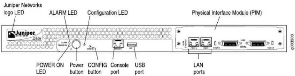
For information about the components of the front panel, see the following sections:
■Juniper Networks Logo LED on page 16
■ALARM LED on page 16
■Power Button and POWER LED on page 16
■CONFIG Button on page 17
■Console Port on page 18
■J2300 USB Port on page 18
Juniper Networks Logo LED
The Juniper Networks logo LED is located on the top-left corner on the front panel (see Figure 5). Table 7 on page 16 describes the blue Juniper Networks logo LED.
Table 7: Juniper Networks Logo LED
| DescriptionStateColor | |
| Router is unplugged, powered off, or malfunctioning.OffBlue | |
| Router is functioning normally.On steadily | |
| Blinking | ■ Router is booting and not yet forwarding traffic.Or■ Router is operating but unable to forward traffic because of a problem.For a list of alarms that can occur on the router, see “Chassis Alarm Conditions” on page 178. |
ALARM LED
The ALARM LED is located to the left of the power button on the front panel (see Figure 5). The yellow (amber) LED lights to indicate a critical condition that can result in a system shutdown or a less severe condition that requires monitoring or maintenance. When the condition is corrected, the light turns off.

NOTE: The ALARM LED on the Services Router lights yellow whether the alarm condition is major (red) or minor (yellow).
To deactivate alarms, you must clear the condition that caused the alarm. For a list of alarms that can occur on the router, see "Chassis Alarm Conditions" on page 178.
Power Button and POWER LED
The power button is located on the left side of the front panel (see Figure 5). You can use the power button to power the Services Router on and off. When you power on the router, the Routing Engine boots as the power supply completes its startup sequence.
The POWER LED is located to the left of the power button on the front panel. Table 8 on page 17 describes the POWER LED.
Table 8: POWER LED
| DescriptionStateColor | |
| Router is unplugged, or is powered off and in standby mode.OffGreen | |
| Router is powered on and is either booting or functioning normally.On steadily | |
| Blinking | Power button has been pressed and quickly released, and the router is gracefully shutting down. |
After the router is powered on, status indicators—such as LEDs on the front panel and show chassis command output—can take up to 60 seconds to indicate that the power supply is functioning normally. Ignore error indicators that appear during the first 60 seconds.
If you need to power off the router after the Routing Engine finishes booting, use the J-Web interface or the CLI to halt the Services Router first. For instructions, see the J-series Services Router Administration Guide.
To power off a Services Router, you can shut it down in one of the following ways:
■ Graceful shutdown—Press and release the power button. The router begins gracefully shutting down the operating system and then powers itself off.
- Immediate shutdown—Press the power button and hold it for more than 5 seconds. The router immediately powers itself off without shutting down the operating system.
CONFIG Button
Use the CONFIG button to return the router to either the rescue configuration or the factory default configuration. The CONFIG button is recessed to prevent it from being pressed accidentally.
The CONFIG button performs two recovery operations:
■ Rescue—Press and release the CONFIG button to load and commit the rescue configuration, if you have set it. To set the rescue configuration, see the J-series Services Router Basic LAN and WAN Access Configuration Guide.
- Clear—Press and hold the CONFIG button for 15 seconds or more, until the configuration LED blinks red to indicate the clear operation is in progress. The clear operation deletes all configurations on the router (including the rescue configuration and backup configurations) and loads and commits the factory configuration.

CAUTION: Pressing and holding the CONFIG button for 15 seconds or more deletes all configurations on the router and loads and commits the factory configuration.
You can change the default behavior of the CONFIG button. For more information, see the J-series Services Router Basic LAN and WAN Access Configuration Guide.
Table 9 on page 18 describes the configuration LED.
Table 9: Configuration LED
| DescriptionStateColor | |
| Rescue configuration is being loaded.BlinkingGreen | |
| Rescue or factory configuration is loaded and committed.On steadily | |
| BlinkingRed | ■ Current committed configuration and all previous versions are being deleted.■ Factory configuration is being loaded. |
| Operation to return the router to the rescue or factory configuration failed.On steadily | |
Console Port
You can use the console port on the chassis front panel to connect to the Routing Engine through an RJ-45 serial cable. From the chassis console port, you can use the CLI to configure the router. The console port is configured as data terminal equipment (DTE) and supports the RS-232 (EIA-232) standard.
For information about securing the chassis console port, see the J-series Services Router Administration Guide.
For pinout information, see "Chassis Console Port Pinouts" on page 199.
J2300 USB Port
The slot labeled USB on the front panel of the router (see Figure 5) accepts a USB storage device or USB storage device adapter with a compact flash disk installed, as defined in the CompactFlash Specification published by the CompactFlash Association. When the USB storage device is installed and configured, it automatically acts as a secondary boot device, if the primary compact flash disk fails on startup. Depending on the size of the USB storage device, you can also configure it to receive any core files generated during a failure. For information about configuring a USB storage device, see the J-series Services Router Administration Guide.

NOTE: For a list of supported USB storage devices, see the J-series Services Router Release Notes at http://www.juniper.net.
J2300 Physical Interface Module (PIM)
The PIMs in J2300 Services Routers are fixed and not interchangeable, with different chassis types providing different PIMs. The PIMs provide the physical connection to various network media types. J2300 Services Routers are available with different types of chassis. Each chassis type contains two Fast Ethernet LAN ports, one set of WAN ports, and additional fixed PIMs of different types. For more information, see "J2300 Chassis with Fixed PIMs" on page 37.
For pinouts of PIM cable connectors, see “Network Cable Specifications and Connector Pinouts” on page 189.
J2300 LAN Ports
The J2300 Services Routers include two fixed 10/100Base-TX Fast Ethernet ports. The LAN ports receive incoming packets from the network and transmit outgoing packets to the network. Each port is equipped with a dedicated network processor that forwards incoming data packets to the Routing Engine, and receives outgoing data packets from the Routing Engine.
The LAN ports are located on the front panel of the router (see Figure 5) and are configured like the ports on a Physical Interface Module (PIM). The LAN ports are not field-replaceable. The ports, labeled PORT 0 and PORT 1, correspond to fe-0/0/0 and fe-0/0/1, respectively, for configuration.
For pinouts of Fast Ethernet cable connectors, see “Network Cable Specifications and Connector Pinouts” on page 189.
Each port has two LEDs located on each side of the bottom of the port. Table 10 on page 19 describes the LAN port LEDs.
Table 10: LEDs for Fast Ethernet LAN Ports
| DescriptionStateColorFunction | |
| Online and link is operational.On steadilyGreen (100 Mb) | |
| Yellow (10 Mbps) | |
| Link is unavailable.DisconnectedRed | |
| Online with network traffic.BlinkingGreenACTIVITY | |
| Online without traffic.On steadily |
J2300 Power System
The J2300 Services Router uses either AC or DC power. The autosensing power supply (see Figure 2 or Figure 3) distributes the different output voltages to the router components according to their voltage requirements.
The power supply is fixed in the chassis and is not field-replaceable. An AC power supply has a single AC appliance inlet that requires a dedicated AC power feed. The DC power supply has a terminal block that provides a single DC input (-48 VDC and return) requiring a dedicated 15 A (-48 VDC) circuit breaker.
For information about site power preparations, see “Power Guidelines, Requirements, and Specifications” on page 85. For information about connecting the router to power and ground, see “Connecting Power” on page 98.
J2300 Cooling System
The cooling system includes a fan on the rear of the Routing Engine's processor and a fan on the power supply.
The airflow produced by these fans keeps router components within the acceptable temperature range (see Figure 6). The speed of the fan at the rear of the processor is adjusted automatically according to current temperature.
Figure 6: Airflow Through the J2300 Chassis

The Routing Engine monitors the temperature of the router components. If the ambient maximum temperature specification is exceeded and the router cannot be adequately cooled, the Routing Engine shuts down the hardware components.
J4300 and J6300 Services Router Hardware Features
This section contains the following topics:
■J4300 and J6300 Chassis on page 21
■Midplane on page 25
■J4300 and J6300 Routing Engine on page 25
■J4300 and J6300 Front Panel on page 26
■J4300 and J6300 Physical Interface Modules (PIMs) on page 29
■J4300 Power System on page 29
■J6300 Power System on page 29
■J4300 and J6300 Cooling System on page 30
J4300 and J6300 Chassis
The J4300 and J6300 Services Router chassis is a rigid sheet metal structure that houses all the other router components (see Figure 7 through Figure 12). The chassis can be installed in many types of racks or cabinets. For information about acceptable rack types, see “Rack Requirements” on page 82.
In addition to the features described in subsequent sections, the chassis includes the following features:
■One pair of metal brackets attached to the side of the chassis. You can use the brackets for mounting the chassis in a rack or cabinet.
■One protective earthing terminal, a PEM nut at the rear of the chassis.
■One electrostatic discharge (ESD) point, a banana plug receptacle at the front of the chassis.
!
CAUTION: Before removing or installing components of a functioning router, attach an ESD strap to an ESD point and place the other end of the strap around your bare wrist. Failure to use an ESD strap could result in damage to the router.
The router must be connected to earth ground during normal operation. The protective earthing terminal on the rear of the chassis is provided to connect the router to ground (see Figure 8). Additional grounding is provided to an AC-powered router when you plug its power supply into a grounded AC power receptacle.
For additional safety information, see “Safety and Regulatory Compliance Information” on page 205.
Figure 7: Front of J4300 and J6300 Chassis

Figure 8: Rear of AC-Powered J4300 Chassis

Figure 9: Rear of DC-Powered J4300 Chassis

Figure 10: Rear of AC-Powered J6300 Chassis

Figure 11: Rear of DC-Powered J6300 Chassis
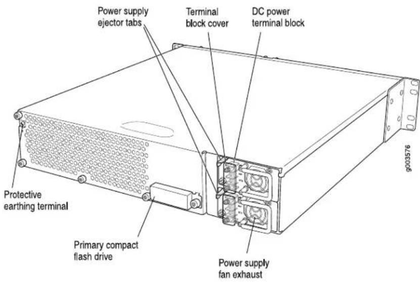
Figure 12: J4300 and J6300 Hardware Components

Front
Table 11 on page 24 summarizes the physical specifications for the J4300 and J6300 router chassis.
Table 11: J4300 and J6300 Physical Specifications
| ValueDescription | |
| Chassis dimensions | ■ 3.50 in. (8.9 cm) high■ 17.00 in. (43.2 cm) wide—19 in. (48.3 cm) wide with mounting brackets attached■ 19.00 in. (48.3 cm) deep—plus 0.5 in. (1.27 cm) of hardware that protrudes from the chassis front |
| Router weight | ■ J4300 router minimum configuration (no PIMs): 18 lb (8.2 kg)■ J4300 router maximum configuration (six PIMs): 21 lb (9.5 kg)■ J6300 router minimum configuration (no PIMs and one power supply): 18.5 lb (8.4 kg)■ J6300 router maximum configuration (six PIMs and two power supplies): 24 lb (10.9 kg) |
Midplane
The midplane is located in the center of the chassis and forms the rear of the PIM card cage (see Figure 12). You install the PIMs into the midplane from the front of the chassis. Data packets are transferred across the midplane from the PIM to the Routing Engine, and from the Routing Engine across the midplane to the destination PIM.
J4300 and J6300 Routing Engine
The Routing Engine provides three main functions:
■Creates the packet forwarding switch fabric for the Services Router, providing route lookup, filtering, and switching on incoming data packets, then directing outbound packets to the appropriate interface for transmission to the network.
■ Maintains the routing tables used by the router and controls the routing protocols that run on the router.
■Provides control and monitoring functions for the router, including controlling power and monitoring system status.
The Routing Engine consists of the following components:
- Processor—Creates the packet forwarding switch fabric for the router and runs JUNOS Internet software to maintain the router's routing tables and routing protocols.
■ DRAM—Buffers incoming packets and provides storage for the routing and forwarding tables and for other Routing Engine processes.
To view the amount of DRAM installed on your router, issue the show chassis routing-engine command.
■EPROM—Stores the serial number of the Routing Engine.
To view the serial number of the Routing Engine, issue either the show chassis routing-engine command or the show chassis hardware command.
- Compact flash drive—Provides primary storage for software images, configuration files, and microcode. The primary compact flash drive is accessible from the rear of the router. For information about replacing the primary compact flash drive, see “Removing and Installing the Primary Compact Flash Disk” on page 161.

NOTE: The J4300 and J6300 Services Routers also provide a slot on the front panel in which you can insert an additional removable compact flash. For information about the removable compact flash, see "J4300 and J6300 Removable Compact Flash Drive" on page 28.
J4300 and J6300 Boot Devices
The J4300 and J6300 Services Routers can boot from three devices:
■Primary compact flash disk
■Removable compact flash disk
■USB storage device
Normally, the Services Router boots from the primary compact flash disk. If the compact flash disk fails, the router attempts to boot from the removable compact flash disk, which is the alternate boot device. If the removable compact flash disk is not present or fails, the router attempts to boot from the USB storage device.
J4300 and J6300 Front Panel
The front panel of a J4300 or J6300 Services Router (Figure 13) allows you to view router status LEDs, access the console port, connect to LAN ports, and perform simple control functions.
Figure 13: Front Panel of J4300 and J6300

The components of the front panel, from left to right, are described in the following sections:
■Juniper Networks Logo LED on page 27
■ALARM LED on page 27
■Power Button and POWER LED on page 27
■CONFIG Button on page 27
■Console Port on page 27
■USB Port on page 27
■J4300 and J6300 LAN Ports on page 28
■J4300 and J6300 Removable Compact Flash Drive on page 28
Juniper Networks Logo LED
The Juniper Networks logo LED on J4300 and J6300 Services Routers functions identically to the Juniper Networks logo LED on the J2300 Services Router. See “Juniper Networks Logo LED” on page 16.
ALARM LED
The ALARM LED on J4300 and J6300 Services Routers functions identically to the ALARM LED on the J2300 Services Router. See “ALARM LED” on page 16.
Power Button and POWER LED
The power button and POWER LED on J4300 and J6300 Services Routers function identically to the power button and POWER LED on the J2300 Services Router. See "Power Button and POWER LED" on page 16.
CONFIG Button
The CONFIG button and LED on J4300 and J6300 Services Routers function identically to the CONFIG button and configuration LED on the J2300 Services Router. See "CONFIG Button" on page 17.
Console Port
You can use the console port on the chassis front panel to connect to the Routing Engine through an RJ-45 serial cable. From the chassis console port, you can use the CLI to configure the router. The console port is configured as data terminal equipment (DTE) and supports the RS-232 (EIA-232) standard.
For information about securing the chassis console port, see the J-series Services Router Administration Guide.
For pinout information, see "Chassis Console Port Pinouts" on page 199.
USB Port
The slot labeled USB on the front panel of the J-series Services Router (see Figure 13) accepts a USB storage device or USB storage device adapter with a compact flash disk installed, as defined in the CompactFlash Specification published by the CompactFlash Association. When the USB storage device is installed and configured, it automatically acts as a secondary boot device, if the primary or removable compact flash disk fails on startup. Depending on the size of the USB storage device, you can also configure it to receive any core files generated during a failure. For information about configuring a USB storage device, see the J-series Services Router Administration Guide.

NOTE: For a list of supported USB storage devices, see the J-series Services Router Release Notes at http://www.juniper.net.
J4300 and J6300 LAN Ports
The J4300 and J6300 Services Routers include two fixed 10/100Base-TX Fast Ethernet ports. The LAN ports receive incoming packets from the network and transmit outgoing packets to the network. Each port is equipped with a dedicated network processor that forwards incoming data packets to the Routing Engine, and receives outgoing data packets from the Routing Engine.
The LAN ports are located on the front panel of the router (see Figure 13) and are configured like the ports on a Physical Interface Module (PIM). The LAN ports are not field-replaceable. The ports, labeled PORT 0 and PORT 1, correspond to fe-0/0/0 and fe-0/0/1, respectively, for configuration.
For pinouts of Fast Ethernet cable connectors, see “Network Cable Specifications and Connector Pinouts” on page 189.
Each port has two LEDs located on each side of the bottom of the port. Table 10 on page 19 describes the LAN port LEDs.
J4300 and J6300 Removable Compact Flash Drive
The slot labeled COMPACT FLASH on the front panel of the Services Router (see Figure 13) is a removable compact flash drive that accepts a type I or II compact flash disk, as defined in the CompactFlash Specification published by the CompactFlash Association. When the removable compact flash disk is installed and configured, it automatically acts as the secondary boot device if the primary compact flash drive fails on startup.
Depending on the capacity of the removable compact flash disk, you can also configure it to receive any core files generated during a failure. For information about configuring a removable compact flash disk, see the J-series Services Router Administration Guide.
The IN USE LED indicates that the removable compact flash is being accessed. Table 12 on page 28 describes the meaning of the LED states.
Table 12: IN USE LED
| DescriptionStateColor | |
| On steadilyRed | Router has booted from the removable compact flash drive.request system snapshot operation has been executed, and files are being copied to or from the removable compact flash drive.Core dump of the kernel is being written to the removable compact flash drive.savecore process is retrieving core dump information. |
J4300 and J6300 Physical Interface Modules (PIMs)
Physical Interface Modules (PIMs) provide the physical connection to various network media types. For more information, see “Field-Replaceable PIMs” on page 47.
For pinouts of PIM cable connectors, see “Network Cable Specifications and Connector Pinouts” on page 189. For PIM replacement instructions, see “Replacing a PIM” on page 156.
J4300 Power System
The J4300 Services Router uses either AC or DC power. The autosensing power supply (see Figure 8 or Figure 9) distributes the different output voltages to the router components according to their voltage requirements.
The power supply is fixed in the chassis, and is not field-replaceable. An AC power supply has a single AC appliance inlet that requires a dedicated AC power feed. The DC power supply has a terminal block that provides a single DC input (-48 VDC and return) that requires a dedicated 15 A (-48 VDC) circuit breaker.
For information about site power preparations, see “Power Guidelines, Requirements, and Specifications” on page 85. For information about connecting the router to power and ground, see “Connecting Power” on page 98.
J6300 Power System
The J6300 Services Router uses either AC or DC power. You can install one or two autosensing, load-sharing power supplies at the bottom rear of the chassis, as shown in Figure 10 or Figure 11. The power supplies distribute the different output voltages to the router components, depending on their voltage requirements. When the power supplies are installed and operational, they automatically share the electrical load.
For full redundancy, two power supplies are required. If a power supply stops functioning for any reason, the second power supply instantly begins providing all the power the router needs for normal functioning. It can provide full power indefinitely.
Each power supply has an LED located on the power supply faceplate. Table 13 on page 29 describes the J6300 power supply LED.
Table 13: J6300 Power Supply LED
| DescriptionState |
| No power flowing to the power supply.Off |
| Power supply is working correctly.Green |
| Power supply is starting up, or has failed.Red |
For information about site power preparations, see “Power Guidelines, Requirements, and Specifications” on page 85. For information about connecting the router to power and ground, see “Connecting Power” on page 98.
Redundant power supplies on the J6300 are hot-removable and hot-insertable; you can remove and replace a redundant power supply without powering down the router or disrupting the routing functions. To avoid electrical injury, carefully follow the instructions in "Replacing Power System Components" on page 170.

WARNING: DC-powered Services Routers are intended for installation only in a restricted access location.
J4300 and J6300 Cooling System
The cooling system includes a fan on the rear of the Routing Engine's processor and a fan at the front of the chassis.
The airflow produced by these fans keeps router components within the acceptable temperature range (see Figure 14). The speed of the fan at the rear of the processor is adjusted automatically according to current temperature.
An additional fan is part of each power supply. This fan is not regulated by the operating system.
Figure 14: Airflow Through the J4300 and J6300 Chassis

Front
The Routing Engine monitors the temperature of the router components. If the ambient maximum temperature specification is exceeded and the router cannot be adequately cooled, the Routing Engine shuts down the hardware components.
Software Overview
Each J-series Services Router runs the JUNOS Internet software on its general-purpose processors. Designed for the large production networks typically supported by Internet service providers (ISPs), the JUNOS software includes processes for Internet Protocol (IP) routing and for managing interfaces, networks, and the router chassis.
The JUNOS Internet software runs on the Routing Engine. The Routing Engine kernel coordinates communication among the JUNOS software processes and provides a link to the Packet Forwarding Engine.
With the J-Web interface and the command-line interface (CLI) to the JUNOS software, you configure the routing protocols that run on the Services Router and set the properties of its network interfaces. After activating a software configuration, use either user interface to monitor the protocol traffic passing through the router, manage operations, and diagnose protocol and network connectivity problems.
This section contains the following topics:
■Routing Engine and Packet Forwarding Engine on page 31
■Kernel and Microkernel on page 31
■JUNOS Software Processes on page 32
■User Interfaces on page 33
Routing Engine and Packet Forwarding Engine
A Services Router has two primary software processing components:
■ Routing Engine—Creates and maintains the routing tables that determine how packets are routed through the network.
- Packet Forwarding Engine—Processes packets; applies filters, routing policies, and other features; and forwards packets to the next hop along the route to their final destination.
For information about Routing Engine hardware, see "J2300 Routing Engine" on page 14 or "J4300 and J6300 Routing Engine" on page 25.
Kernel and Microkernel
The Routing Engine kernel provides the underlying infrastructure for all JUNOS software processes by doing the following:
■Linking the routing tables maintained by the routing protocol process with the forwarding table maintained by the Routing Engine
■Coordinating communication with the Packet Forwarding Engine, primarily by synchronizing the Packet Forwarding Engine's forwarding table with the master forwarding table maintained by the Routing Engine
The microkernel contains device drivers and processes that the Packet Forwarding Engine uses to govern the flow of packets through the Services Router.
JUNOS Software Processes
The JUNOS software running on the Routing Engine and Packet Forwarding Engine consists of multiple processes that are responsible for individual Services Router functions.
The separation of functions provides operational stability, because each process accesses its own protected memory space. In addition, because each process is a separate software package, you can selectively upgrade all or part of the JUNOS software, for added flexibility.
Table 14 on page 32 describes the primary JUNOS software processes.
Table 14: JUNOS Software Processes
| DescriptionNameProcess | ||
| process | mgdManagement | Manages the Services Router system as follows:■ Provides communication between the other processes and an interface to the configuration database■ Populates the configuration database with configuration information and retrieves the information when queried by other processes to ensure that the system operates as configured■ Interacts with the other processes when commands are issued through one of the user interfaces on the router |
| process | chassisdChassis | Controls a Services Router chassis and its components as follows:■ Detects hardware on the system that is used to configure network interfaces■ Monitors the physical status of hardware components and field-replaceable units (FRUs), detecting when environment sensors such as temperature sensors are triggered■ Relays signals and interrupts—for example, when devices are taken offline, so that the system can close sessions and shut down gracefully |
| protocol process | rpdRouting | Defines how routing protocols such as RIP, OSPF, and BGP operate on the router, including selecting routes and maintaining fowarding tables. |
| process (also called device control process) | dcdInterface | Supplies the programs that configure and monitor network interfaces by defining physical characteristics such as link encapsulation, hold times, and keepalive timers. |
| process | fwddForwarding | Responsible for most of the packet transmission through a Services Router. The overall performance of the router is largely determined by the effectiveness of the forwarding process. |
User Interfaces
The user interfaces on a Services Router interact with the management process to execute commands and store and retrieve information from the configuration database. The user interfaces operate as clients that communicate with the JUNOS Internet software through an application programming interface (API).
The following primary user interfaces are shipped with the router:
■ J-Web graphical user interface—Includes quick configuration capabilities for performing the minimum required steps to enable a feature, plus a built-in configuration editor with access to the entire configuration hierarchy to fully configure the router. The J-Web interface also provides tools for monitoring, managing, and diagnosing router operation.
■ Command-line interface (CLI)—Grants access to the complete JUNOS command and configuration hierarchies, to monitor the router, diagnose problems, and configure it completely.
For more information, see "Services Router User Interface Overview" on page 61.
Other user interfaces for the Services Router interact with the management process through the common API interface. These interfaces are designed to facilitate the configuration of one or, in some cases, many routers on the network. Among the supported interfaces are the JUNOScope and Service Deployment System (SDX) applications. For more information about these products, see the JUNOScope Software User Guide and the SDX Software Basics Guide.
J2300, J4300, and J6300 Services Router Getting Started Guide
Chapter 3
Physical Interface Modules Overview
J-series Services Routers accept Physical Interface Modules (PIMs) in the slots on the front of the chassis.

CAUTION: PIMs are not hot-swappable. You must power off the Services Router before removing or inserting a PIM. Ensure that the PIMs are installed in the router chassis before booting up the system.
A Physical Interface Module (PIM) is a network interface card that is installed on a J-series Services Router, to provide physical connections to a LAN or a WAN. The PIM receives incoming packets from the network and transmits outgoing packets to the network. Each PIM is equipped with a dedicated network processor that forwards incoming data packets to the Routing Engine, and receives outgoing data packets from the Routing Engine. During this process, the PIM performs framing and line-speed signaling for its medium type.
For a complete list of supported PIMs, see "Field-Replaceable PIMs" on page 47.
For a J-series Services Router PIM compatibility matrix and datasheets, go to http://www.juniper.net/products/jseries/.
For information about network interfaces, and for configuration instructions, see the J-series Services Router Basic LAN and WAN Access Configuration Guide.
This chapter contains the following topics.
■PIM Terms on page 36
■J2300 Chassis with Fixed PIMs on page 37
■Field-Replaceable PIMs on page 47
PIM Terms
To understand PIMs, become familiar with the terms defined in Table 15 on page 36.
Table 15: PIM Terms
| DefinitionTerm | |
| ADSL 2/2 + Annex A | ITU-T Standard G.992.1 that defines how ADSL works over plain old telephone service (POTS) lines. |
| ADSL 2/2 + Annex B | ITU-T Standard G.992.1 that defines how ADSL works over Integrated Services Digital Network (ISDN) lines. |
| bandwidth on demand | ISDN cost-control feature defining the bandwidth threshold that must be reached on all links before a Services Router initiates additional ISDN data connections to provide more bandwidth. |
| Basic Rate Interface (BRI) | ISDN interface intended for home and small enterprise applications. BRI consists of two 64-Kbps B-channels and one 16-Kbps D-channel. |
| callback | Alternative feature to dial-in that enables a J-series Services Router to call back the caller from the remote end of a backup ISDN connection. Instead of accepting a call from the remote end of the connection, the router rejects the call, waits a configured period of time, and calls a number configured on the router's dialer interface. See also dial-in. |
| caller ID | Telephone number of the caller on the remote end of a backup ISDN connection, used to dial in and also to identify the caller. Multiple caller IDs can be configured on an ISDN dialer interface. During dial-in, the router matches the incoming call's caller ID against the caller IDs configured on its dialer interfaces. Each dialer interface accepts calls from only callers whose caller IDs are configured on it. |
| channel service unit (CSU) | Unit that connects a digital telephone line to a multiplexer or other signal service. |
| data service unit (DSU) | Unit that connects a data terminal equipment (DTE) device—in this case, a Services Router—to a digital telephone line. |
| data terminal equipment-to-data communication equipment (DTE-DCE) interface | Interface that a Services Router (the DTE) uses to exchange information with a serial device such as a modem (the DCE).A DTE cable uses a male 9-pin or 25-pin connector, and a DCE cable uses a female 9-pin or 25-pin connector. |
| demand circuit | Interface configured for dial-on-demand routing backup. In OSPF, the demand circuit reduces the amount of OSPF traffic by removing all OSPF protocols when the routing domain is in a steady state. |
| dial backup | Feature that reestablishes network connectivity through one or more backup ISDN dialer interfaces after a primary interface fails. When the primary interface is reestablished, the ISDN interface is disconnected. |
| dial-in | Feature that enables J-series Services Routers to receive calls from the remote end of a backup ISDN connection. The remote end of the ISDN call might be a service provider, a corporate central location, or a customer premises equipment (CPE) branch office. All incoming calls can be verified against caller IDs configured on the router's dialer interface. See also callback. |
| dialer filter | Stateless firewall filter that enables dial-on-demand routing backup when applied to a physical ISDN interface and its dialer interface configured as a passive static route. The passive static route has a lower priority than dynamic routes. If all dynamic routes to an address are lost from the routing table and the router receives a packet for that address, the dialer interface initiates an ISDN backup connection and sends the packet over it. See also dial-on-demand routing backup: floating static route. |
| dial-on-demand-routing (DDR) backup | Feature that provides a J-series Services Router with full-time connectivity across an ISDN line. When routes on a primary serial T1, E1, T3, E3, Fast Ethernet, or PPPoE interface are lost, an ISDN dialer interface establishes a backup connection. To save connection time costs, the Services Router drops the ISDN connection after a configured period of inactivity. Services Router with ISDN interfaces support two types of dial-on-demand routing backup: on-demand routing with a dialer filter and dialer watch. See also dialer filter: dialer watch. |
| dialer watch | Dial-on-demand routing (DDR) backup feature that provides reliable connectivity without relying on a dialer filter to activate the ISDN interface. The ISDN dialer interface monitors the existence of each route on a watch list. If all routes on the watch list are lost from the routing table, dialer watch initiates the ISDN interface for failover connectivity. See also dial-on-demand routing backup. |
| “dying gasp” notification | Ability of a Services Router with a digital subscriber line (DSL) connection that has lost power to send a message informing the attached DSL access multiplexer (DSLAM) that it is about to go offline. |
| floating static route | Route with an administrative distance greater than the administrative distance of the dynamically learned versions of the same route. The static route is used only when the dynamic routes are no longer available. When a floating static route is configured on an interface with a dialer filter, the interface can be used for backup. |
| ISDN S/T interface | Interface between an ISDN network and a network termination device consisting of two twisted pairs, one each for transmitting and receiving. The S/T interface usually resides in the customer premises and operates at 192 Kbps, of which ISDN traffic accounts for 144 Kbps. |
| ISDN U interface | Single twisted-pair interface line connecting the customer premises unit in an ISDN network to the central office. A U interface runs at 144 Kbps (128 Kbps for two B channels and 16 Kbps for the D channel). |
| plain old telephone service (POTS) | Standard telephone service that allows limited speed and bandwidth of 52 Kbps, which is also know as public switched telephone network (PSTN). |
J2300 Chassis with Fixed PIMs
The PIMs in J2300 Services Routers are fixed and not interchangeable. All J2300 chassis types have two Fast Ethernet LAN ports and one set of WAN ports. The J2300 Services Routers provide the chassis types summarized in Table 16 on page 38 and described in the following sections:
■J2300 Chassis PIM Summary on page 38
■Dual-Port Serial Chassis on page 39
■Dual-Port Serial with ISDN BRI Chassis on page 40
■Dual-Port T1 or E1 Chassis on page 41
■Dual-Port T1 or E1 with ISDN BRI Chassis on page 43
■Dual-Port G.SHDSL Chassis on page 44
■Dual-Port G.SHDSL with ISDN BRI S/T Chassis on page 45
J2300 Chassis PIM Summary
Table 16 on page 38 provides software release information, port numbers, and sample interface names for J2300 Services Router chassis types.
Table 16: J2300 Chassis PIM Summary
| Sample Interface Names(type-pim/0/port)Port NumberingSoftware ReleaseChassis Type | |||
| Dual-Port Serial | JUNOS 7.0 and later | Ports—0 and 1 for Fast Ethernet interfaces | fe-0/0/0se-0/0/2 |
| Ports—2 and 3 for serial interfaces | |||
| Dual-Port Serial with one ISDN BRI port | JUNOS 7.3 and later | Ports—0 and 1 for Fast Ethernet interfaces | fe-0/0/0se-0/0/2 |
| Ports—2 and 3 for serial interfaces | br-0/0/4 | ||
| Port—4 for the ISDN BRI interface | |||
| Dual-Port T1 or E1 | JUNOS 7.0 and later | Ports—0 and 1 for Fast Ethernet interfaces | fe-0/0/0t1-0/0/2 |
| Ports—2 and 3 for T1 or E1 interfaces | e1-0/0/2 | ||
| Dual-Port T1 or E1 with one ISDN BRI port | JUNOS 7.5 and later | Ports—0 and 1 for Fast Ethernet interfaces | fe-0/0/0t1-0/0/2 |
| Ports—2 and 3 for T1 or E1 interfaces | e1-0/0/2 | ||
| Port—4 for the ISDN BRI interface | br-0/0/4 | ||
| Dual-Port G.SHDSL | JUNOS 7.5 and later | Ports—0 and 1 for Fast Ethernet interfaces | fe-0/0/0at-0/0/2 |
| Ports—2 and 3 for G.SHDSL interfaces | |||
| Dual-Port G.SHDSL with one ISDN BRI S/T port | JUNOS 7.5 and later | Ports—0 and 1 for Fast Ethernet interfaces | fe-0/0/0 |
| Ports—2 and 3 for G.SHDSL interfaces | at-0/0/2 | ||
| Port—4 for the ISDN BRI S/T interface | br-0/0/4 | ||
Dual-Port Serial Chassis
The J2300 Dual-Port Serial chassis has two Fast Ethernet LAN ports and two serial WAN ports as shown in Figure 15.
Figure 15: J2300 Serial Chassis

The Dual-Port Serial chassis provides the following key features:
■Onboard network processor
■Autoselection of operation modes based on data terminal equipment (DTE) or data communication equipment (DCE) cables
■Local and remote loopback diagnostics
■Configurable clock rate for the transmit (Tx) clock and receive (Rx) clock
For pinouts of cable connectors for the network ports, see “Network Cable Specifications and Connector Pinouts” on page 189.
For alarms, see the configuring and monitoring alarms information in the J-series Services Router Administration Guide.
Table 17 on page 40 describes the meaning of the LEDs for a Fast Ethernet port, and Table 18 on page 40 describes the meaning of the status LED for a serial port.
Table 17: LEDs for Fast Ethernet LAN Ports
| DescriptionStateColorLabel | |
| LINK/SPEED | Online and link is operational.On steadilyGreen (100 Mbps) |
| Yellow (10 Mbps) | |
| Link is unavailable.DisconnectedRed | |
| ACTIVITY | Online with network traffic.BlinkingGreen |
| Online without traffic.On steadily |
Table 18: Status LED for Serial Ports
| DescriptionStateColor | |
| Online with no alarms or failures.On steadilyGreen | |
| On steadilyRed | Active with a local alarm. The router has detected a failure. |
| Offline.OffUnlit |
Dual-Port Serial with ISDN BRI Chassis
The J2300 Dual-Port Serial with ISDN BRI chassis has two Fast Ethernet LAN ports, two serial WAN ports, and one ISDN BRI U (Figure 16) or S/T (Figure 17) port. The ISDN BRI interface is the backup interface to the primary serial interface and provides failover support for a serial connection.
Figure 16: J2300 Serial with ISDN BRI U Chassis

Figure 17: J2300 Serial with ISDN BRI S/T Chassis

The serial with ISDN BRI S/T or U interface chassis provides the following key features:
■Onboard network processor
■Autoselection of operation modes based on data terminal equipment (DTE) or data communication equipment (DCE) cables
■Local and remote loopback diagnostics
■Configurable clock rate for the transmit (Tx) clock and receive (Rx) clock
■Bandwidth on demand
■Dial backup
■Dial-on-demand routing backup
For pinouts of cable connectors for the network ports, see “Network Cable Specifications and Connector Pinouts” on page 189.
For alarms, see configuring and monitoring alarms information in the J-series Services Router Administration Guide.
Table 17 on page 40 describes the meaning of the LEDs for a Fast Ethernet port, Table 19 on page 41 describes the meaning of the status LED for a serial port, and Table 20 on page 41 describes the meaning of the status LED for an ISDN BRI port.
Table 19: Status LED for Serial Ports
| DescriptionStateColor | |
| Online with no alarms or failures.On steadilyGreen | |
| On steadilyRed | Active with a local alarm. The router has detected a failure. |
| Offline.OffUnlit |
Table 20: Status LED for ISDN BRI Port
| DescriptionStateColor |
| PIM is online and operational.On steadilyGreen |
| PIM is not operational and needs replacement.DisconnectedRed |
| PIM is offline.OffUnlit |
Dual-Port T1 or E1 Chassis
The J2300 Dual-Port T1 or E1 chassis has two Fast Ethernet LAN ports and two T1 or E1 WAN ports. Figure 18 shows the E1 chassis, and Figure 19 shows the T1 chassis.
Figure 18: J2300 E1 Chassis

Figure 19: J2300 T1 Chassis

The T1 or E1 chassis provides the following key features:
■Onboard network processor
■ Integrated CSU/DSU—Eliminates the need for a separate external device
■Framed, unframed (E1 only), and fractional operational modes
■56-Kbps and 64-Kbps modes
■ANSI T1.102, T1.107, and T1.403 standards compliance
■G.703, G.704, and G.706 E1 standards compliance
■Independent internal and external clocking system
■ Local and remote loopback, bit error rate test (BERT), T1 facilities data link (FDL), and long buildout diagnostics
For pinouts of cable connectors for the network ports, see "Network Cable Specifications and Connector Pinouts" on page 189.
For alarms, see configuring and monitoring alarms information in the J-series Services Router Administration Guide.
Table 17 on page 40 describes the meaning of the LEDs for a Fast Ethernet port, and Table 21 on page 42 describes the meaning of the status LED for a T1 or E1 port.
Table 21: Status LEDs for T1 and E1 Ports
| DescriptionStateColor | |
| Online with no alarms or failures.On steadilyGreen | |
| On steadilyRed | Active with a local alarm. The router has detected a failure. |
| Offline.OffUnlit |
Dual-Port T1 or E1 with ISDN BRI Chassis
The J2300 Dual-Port T1 or E1 with ISDN BRI chassis has two Fast Ethernet LAN ports, two T1 or E1 WAN ports, and one ISDN BRI port. The ISDN BRI interface is the backup interface to the primary T1 or E1 interface and provides ISDN failover support for a T1 or E1 connection.
The E1 chassis has an ISDN BRI S/T port (Figure 20), and the T1 chassis has an ISDN BRI U port (Figure 21).
Figure 20: J2300 E1 with ISDN BRI S/T Chassis

Figure 21: J2300 T1 with ISDN BRI U Chassis

The T1 or E1 with ISDN BRI chassis provides the following key features:
■Onboard network processor
■ Integrated CSU/DSU—Eliminates the need for a separate external device
■Framed, unframed (E1 only), and fractional operational modes
■56-Kbps and 64-Kbps modes
■ANSI T1.102, T1.107, and T1.403 standards compliance
■G.703, G.704, and G.706 E1 standards compliance
■Independent internal and external clocking system
■ Local and remote loopback, bit error rate test (BERT), T1 facilities data link (FDL), and long buildout diagnostics
■Bandwidth on demand
■Dial backup
■Dial-on-demand routing backup
For pinouts of cable connectors for the network ports, see “Network Cable Specifications and Connector Pinouts” on page 189.
For alarms, see configuring and monitoring alarms information in the J-series Services Router Administration Guide.
Table 17 on page 40 describes the meaning of the LEDs for a Fast Ethernet port, Table 22 on page 44 describes the meaning of the status LED for a T1 or E1 port, and Table 23 on page 44 describes the meaning of the status LED for an ISDN BRI port.
Table 22: Status LEDs for T1 and E1 Ports
| DescriptionStateColor | |
| Online with no alarms or failures.On steadilyGreen | |
| On steadilyRed | Active with a local alarm. The router has detected a failure. |
| Offline.OffUnlit |
Table 23: Status LED for ISDN BRI Port
| DescriptionStateColor |
| PIM is online and operational.On steadilyGreen |
| PIM is not operational and needs replacement.DisconnectedRed |
| PIM is offline.OffUnlit |
Dual-Port G.SHDSL Chassis
The J2300 Dual-Port G.SHDSL chassis has two Fast Ethernet LAN ports and two G.SHDSL WAN ports, as shown in Figure 22. The G.SHDSL ports provide symmetric high-speed digital subscriber line (SHDSL) interfaces to ATM network media for ATM-over-SHDSL connections.
Figure 22: J2300 G.SHDSL Chassis

The G.SHDSL chassis provides the following key features:
■Onboard network processor
■2-port two-wire mode and 1-port four-wire mode

NOTE: Contact the Juniper Networks Technical Assistance Center (JTAC) before implementing 1-port four-wire mode.
■Programmable line rates in both modes:
■2-port two-wire mode supports autodetection of line rate and fixed line rates from 192 Kbps to 2.304 Mbps in 64-Kbps increments.
■ 1-port four-wire mode supports fixed line rates from 384 Kbps to 4.608 Mbps in 128-Kbps increments.
■Up to 16 virtual channels (VCs) per G.SHDSL port
■ATM-over-G.SHDSL framing
■“Dying gasp” notification
■Local and remote loopback diagnostics
■ITU-T G.991.2, ITU-T G.994.1, and ITU-T G.997.1 standards compliance
For pinouts of cable connectors for the network ports, see “Network Cable Specifications and Connector Pinouts” on page 189.
For alarms, see configuring and monitoring alarms information in the J-series Services Router Administration Guide.
Table 17 on page 40 describes the meaning of the LEDs for a Fast Ethernet port, and Table 24 on page 45 describes the meaning of the status LED for a G.SHDSL port.
Table 24: Status LED for G.SHDSL Ports
| DescriptionStateColor | |
| Online with no alarms or failures.On steadilyGreen | |
| On steadilyRed | Active with a local alarm. The router has detected a failure. |
Dual-Port G.SHDSL with ISDN BRI S/T Chassis
The J2300 Dual-Port G.SHDSL with ISDN BRI chassis has two Fast Ethernet LAN ports, two G.SHDSL WAN ports, and one ISDN BRI S/T port as shown in Figure 23. The G.SHDSL ports provide symmetric high-speed digital subscriber line (SHDSL) interfaces to ATM network media for ATM-over-SHDSL connections. The ISDN BRI S/T interface is the backup interface to the primary G.SHDSL interface and provides ISDN failover support for a G.SHDSL connection.
Figure 23: J2300 G.SHDSL with ISDN BRI S/T Chassis

The G.SHDSL with ISDN BRI S/T chassis provides the following key features:
■Onboard network processor
■2-port two-wire mode and 1-port four-wire mode

NOTE: Contact the Juniper Networks Technical Assistance Center (JTAC) before implementing 1-port four-wire mode.
■Programmable line rates in both modes:
■2-port two-wire mode supports autodetection of line rate and fixed line rates from 192 Kbps to 2.304 Mbps in 64-Kbps increments.
■ 1-port four-wire mode supports fixed line rates from 384 Kbps to 4.608 Mbps in 128-Kbps increments.
■Up to 16 virtual channels (VCs) per G.SHDSL port
■ATM-over-G.SHDSL framing
■“Dying gasp” notification
■Local and remote loopback diagnostics
■ITU-T G.991.2, ITU-T G.994.1, and ITU-T G.997.1 standards compliance
■Bandwidth on demand
■Dial backup
■Dial-on-demand routing backup
For pinouts of cable connectors for the network ports, see “Network Cable Specifications and Connector Pinouts” on page 189.
For alarms, see configuring and monitoring alarms information in the J-series Services Router Administration Guide.
Table 17 on page 40 describes the meaning of the LEDs for a Fast Ethernet port, Table 25 on page 46 describes the meaning of the status LED for a G.SHDSL port, and Table 26 on page 47 describes the meaning of the status LED for an ISDN BRI port.
Table 25: Status LEDs for G.SHDSL Ports
| DescriptionStateColor |
| Online with no alarms or failures.On steadilyGreen |
Table 25: Status LEDs for G.SHDSL Ports (continued)
| DescriptionStateColor |
| Active with a local alarm. The router has detected a failure.On steadilyRed |
Table 26: Status LED for ISDN BRI Port
| DescriptionStateColor |
| PIM is online and operational.On steadilyGreen |
| PIM is not operational and needs replacement.DisconnectedRed |
| PIM is offline.OffUnlit |
Field-Replaceable PIMs
PIMs are removable and insertable only when the Services Router is powered off. You can install a PIM into one of the six slots in the router chassis. If a slot is not occupied by a PIM, a PIM blank panel must be installed to shield the empty slot and to allow cooling air to circulate properly through the router.
These Services Routers support the types of PIMs summarized in Table 27 on page 48 and described in the following sections:
■J4300 and J6300 Field-Replaceable PIM Summary on page 48
■Dual-Port Serial PIM on page 49
■Dual-Port T1 or E1 PIM on page 50
■Dual-Port Channelized T1 or E1 PIM on page 51
■T3 or E3 PIM on page 53
■Dual-Port Fast Ethernet PIM on page 54
■4-Port ISDN BRI PIMs on page 55
■ADSL PIM on page 57
■G.SHDSL PIM on page 58
J4300 and J6300 Field-Replaceable PIM Summary
Table 27 on page 48 provides software release information, slot and port numbers, and sample interface names for the field-replaceable PIMs supported on J4300 and J6300 Services Routers.
Table 27: J4300 and J6300 Field-Replaceable PIM Summary
| Sample Interface Name(type-pim/0/port)Slot and Port NumberingSoftware | |||
| JUNOS 7.0 and laterDual-Port Scr | Slots—1 through 6 | se-3/0/1 | |
| Ports—0 and 1 | |||
| JUNOS 7.0 and laterDual-Port T1 | Slots—1 through 6 | t1-0/0/1 | |
| Ports—0 and 1 | or | ||
| e1-0/0/1 | |||
| or E1 | JUNOS 8.1 and laterDual-Port Cha | Shalized Through 6 | ct1-3/0/0 |
| Port—0 and 1 | ce1-3/0/0 | ||
| T3 or E3 | T3 PIM—JUNOS 7.0 and later | Slots—1 through 6 | t3-0/0/0 |
| E3 PIM—JUNOS 7.5 and later | Port—0 | or | |
| e3-2/0/0 | |||
| JUNOS 7.0 and laterDual-Port Fas | SIBer—1 through 6 | fe-1/0/0 | |
| Ports—0 and 1 | |||
| JUNOS 7.3 and later4-Port ISDN | Slots—1 through 6 | br-1/0/2 | |
| Ports—0, 1, 2, and 3 | |||
| ADSL | ADSL Annex A and Annex B—JUNOS 7.2 and later | Slots—1 through 6 | at-2/0/0 |
| ADSL 2/2 + Annex A—JUNOS 7.3 and later | Port—0 | ||
| ADSL 2/2 + Annex B—JUNOS 7.4 and later | |||
| JUNOS 7.4 and laterG.SHDSL | Slots—1 through 6 | at-1/0/0 | |
| Ports—0 and 1 | |||

NOTE: PIMs are not hot-swappable. PIMs must be installed in front panel slots before the system is booted up.
Dual-Port Serial PIM
The Dual-Port Serial PIM (Figure 24) provides a physical connection to serial network media types through two serial interface ports.
Figure 24: Dual-Port Serial PIM

The Dual-Port Serial PIM provides the following key features:
■Onboard network processor
■Autoselection of operation modes based on data terminal equipment (DTE) or data communication equipment (DCE) cables
■Local and remote loopback diagnostics
■Configurable clock rate for the transmit (Tx) clock and receive (Rx) clock
For pinouts of cable connectors for serial PIMs, see "Serial PIM Cable Specifications" on page 189.
For alarms, see the configuring and monitoring alarms information in the J-series Services Router Administration Guide.
For installing and removing a PIM, see "Replacing a PIM" on page 156.
Status LEDs indicate port status. Table 28 on page 49 describes the meaning of the LED states.
Table 28: Status LEDs for Serial Ports
| DescriptionStateColor | |
| Online with no alarms or failures.On steadilyGreen | |
| On steadilyRed | Active with a local alarm. The router has detected a failure. |
Table 28: Status LEDs for Serial Ports (continued)
| DescriptionStateColor |
| Offline.OffUnlit |
Dual-Port T1 or E1 PIM
The Dual-Port T1 PIM (Figure 25) and Dual-Port E1 PIM (Figure 26) provide a physical connection to T1 or E1 network media types. Each PIM has two physical T1 or E1 ports with an integrated channel service unit (CSU) or data service unit (DSU).
Figure 25: Dual-Port T1 PIM

Figure 26: Dual-Port E1 PIM
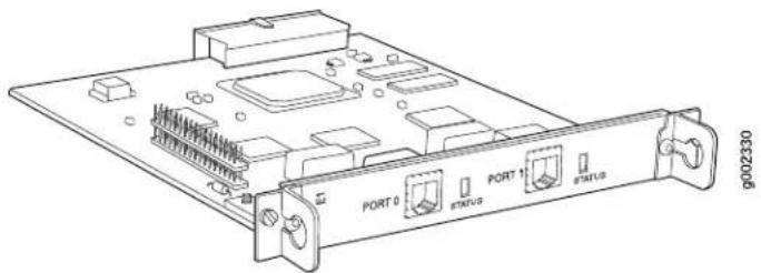
The Dual-Port T1 and E1 PIMs provides the following key features:
■Onboard network processor
■ Integrated CSU/DSU—Eliminates the need for a separate external device
■56-Kbps and 64-Kbps modes
■ANSI T1.102, T1.107, and T1.403 standards compliance
■G.703, G.704, and G.706 E1 standards compliance
■Independent internal and external clocking system
■ Loopback, bit error rate test (BERT), T1 facilities data link (FDL), and long buildout diagnostics
For pinouts of cable connectors for T1 and E1 PIMs, see "E1 and T1 RJ-48 Cable Pinouts" on page 200.
For alarms, see the configuring and monitoring alarms information in the J-series Services Router Administration Guide.
For installing and removing a PIM, see "Replacing a PIM" on page 156.
Status LEDs indicate port status. Table 29 on page 51 describes the meaning of the LED states.
Table 29: Status LEDs for T1 and E1 Ports
| DescriptionStateColor | |
| Online with no alarms or failures.On steadilyGreen | |
| On steadilyRed | Active with a local alarm. The router has detected a failure. |
| Offline.OffUnlit | |
Dual-Port Channelized T1 or E1 PIM
The Dual-Port Channelized T1 or E1 PIM (Figure 27) is a multiflex interface card that allows you to configure a single interface as a channelized T1 interface or a channelized E1 interface. The channelized T1 or E1 interface supports up to 24 DS0 channels on a T1 interface and up to 32 DS0 channels on an E1 interface, in addition to supporting the features of regular (unchannelized) T1 and E1 PIMs. Each interface can be configured as a single clear channel, fractionalized, or channelized interface.

NOTE: You cannot configure a channelized T1 or E1 interface through a J-Web Quick Configuration page.
Figure 27: Channelized T1/E1 PIM

The Dual-Port Channelized T1 or E1 PIM provides the following key features:
■Onboard network processor
■Two-port channelization
■Interfaces that are software configurable as T1 or E1
■Clear-channel, fractional, and channelized operation
■Lower latency due to the addition of a Freescale processor
■Maximum MTU value of 4500 bytes (for channelized T1 or E1 interface)

NOTE: For a clear-channel T1 or E1 interface, the maximum MTU is 9150 bytes.
■56-Kbps and 64-Kbps modes
■ANSI T1.102, T1.107, and T1.403 standards compliance
■G.703, G.704, and G.706 E1 standards compliance
■Independent internal and external clocking system
■ Loopback, bit error rate test (BERT), T1 facilities data link (FDL), and long buildout diagnostics
For pinouts of cable connectors for channelized T1 and E1 PIMs, see “E1 and T1 RJ-48 Cable Pinouts” on page 200.
For alarms, see the configuring and monitoring alarms information in the J-series Services Router Administration Guide.
For installing and removing a PIM, see "Replacing a PIM" on page 156.
Channelized T1 and E1 LEDs indicate PIM and port status. Table 30 on page 52 describes the meaning of the LED states.
Table 30: LEDs for Channelized T1 and E1 PIMs
| DescriptionStateColorLabel | ||
| On steadilyGreenONLINIPIM is online and operational. | ||
| PIM is not online.OffUnlit | ||
| DescriptionStateColorLabel | ||
| On steadilyGreenSTATUS | Port is online with no alarms or failures, and the physical layer is active. | |
| OnlineRed | Port is active with a local alarm. The router has detected a failure and the physical layer is inactive. | |
| OnlineYellow | Port is online with alarms for remote failures. | |
| Port is disabled.OfflineUnlit. | ||
T3 or E3 PIM
The T3 (also known as DS3) PIM (Figure 28) and E3 PIM (Figure 29) are supported on J6300 Services Routers and provide a physical connection to T3 or E3 network media types. The T3 and E3 PIMs include one physical T3 or E3 port with an integrated data service unit (DSU).
Figure 28: T3 PIM

natural_image
Technical line drawing of an electronic device with labeled ports (TX, RX, ATUS) and connectors (no readable text or symbols beyond labels)Figure 29: E3 PIM
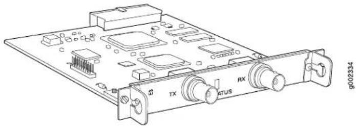
natural_image
Technical line drawing of an electronic device chassis with labeled ports (TX, ATUS, RX) and connectors (no readable text or symbols beyond labels)The T3 and E3 PIMs provide the following key features:
■Onboard network processor
■ Integrated DSU—Eliminates the need for a separate external device
■Subrate and scrambling options with support for major DSU vendors
■Independent internal and external clocking system
■ Loopback (payload-supported only on T3 PIM, local, and remote), bit error rate test (BERT), and T3 far-end alarm and control (FEAC) diagnostics
For pinouts of cable connectors for T3 and E3 PIMs, see “E3 and T3 BNC Connector Pinout” on page 203.
For alarms, see the configuring and monitoring alarms information in the J-series Services Router Administration Guide.
For installing and removing a PIM, see "Replacing a PIM" on page 156.
Status LEDs indicate port status. Table 31 on page 54 describes the meaning of the LED states.
Table 31: Status LEDs for T3 and E3 Ports
| DescriptionStateColor | |
| Online with no alarms or failures.On steadilyGreen | |
| On steadilyRed | Active with a local alarm. The router has detected a failure. |
| On steadilyYellow | ■ Loopback mode.■ T3 (DS3)—Remote endpoint is in red alarm failure.■ E3—Remote defect indication (RDI). |
| Offline.OffUnlit |
Dual-Port Fast Ethernet PIM
The Dual-Port 10/100-Mbps Fast Ethernet PIM (Figure 30) has two physical Fast Ethernet ports.
Figure 30: Fast Ethernet PIM
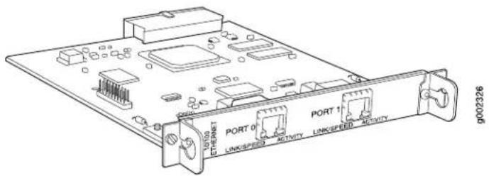
The Dual-Port Fast Ethernet PIM provides the following key features:
■Onboard network processor
■Full-duplex and half-duplex modes
■Media access control (MAC) address filtering
■Autonegotiation through medium-dependent interface (MDI) and MDI crossover (MDI-X) support
For pinouts of cable connectors for Fast Ethernet PIMs, see "RJ-45 Connector Pinout for Fast Ethernet Ports" on page 199.
For alarms, see the configuring and monitoring alarms information in the J-series Services Router Administration Guide.
For installing and removing a PIM, see "Replacing a PIM" on page 156.
Fast Ethernet LEDs indicate link status, port speed, and activity. Table 32 on page 55 describes the meaning of the LEDs.
Table 32: LEDs for Dual-Port Fast Ethernet PIM
| DescriptionStateColorLabel | ||
| LINK/SPEED | Yellow (10 Mbps) | Online and link is active.On steadilyGreen (100 Mbps) |
| Link is unavailable.DisconnectedRed | ||
| ACTIVITY | Online with network traffic.BlinkingGreen | |
| Online without traffic.On steadilyGreen | ||
4-Port ISDN BRI PIMs
The 4-port ISDN BRI PIMs have four physical ports that support the ISDN BRI S/T (Figure 31) or ISDN BRI U (Figure 32) interface type.
Figure 31: ISDN BRI S/T PIM

Figure 32: ISDN BRI U PIM

ISDN BRI PIMs provide the following key features:
■Onboard network processor
■Bandwidth on demand
■Dial backup
■Dial-on-demand routing backup (floating static and dialer watch)
For pinouts of cable connectors for ISDN PIMs, see "ISDN RJ-45 Connector Pinout" on page 204.
For installing and removing a PIM, see "Replacing a PIM" on page 156.
ISDN LEDs indicate PIM and port status. Table 33 on page 57 describes the meaning of the LED states.
Table 33: LEDs for ISDN BRI S/T and U PIMs
| DescriptionStateColorLabel | ||
| ONLINE | BlinkingGreen | Call setup is successful on either the B1 or B2 channel. |
| ISDN Layer 2 is active.On steadilyGreen | ||
| On steadilyAmber | ■ ISDN Layer 1 is active. ■ ISDN Layer 2 is unavailable. | |
| DisconnectedRed | ■ BRI interface port is not connected. ■ ISDN Layer 1 is unavailable. | |
| BRI interface is offline.OffUnlit | ||
| STATUS | PIM is online and operational.On steadilyGreen | |
| PIM is not operational and needs replacement.DisconnectedRed | ||
| PIM is offline.OffUnlit | ||
ADSL PIM
The ADSL PIM provides a single physical interface to asymmetric digital subscriber line (ADSL) network media types. The ADSL PIM, one supporting Annex A (Figure 33) over plain old telephone service (POTS) and the other Annex B (Figure 34) over ISDN, includes one physical ADSL port for an ATM-over-ADSL connection.
Figure 33: ADSL 2/2+ Annex A PIM

Figure 34: ADSL 2/2+ Annex B PIM

The ADSL PIM provides the following key features:
■Onboard network processor
■ADSL, ADSL2, and ADSL2 + protocols on the same PIM
■“Dying gasp” notification
■Asynchronous Transfer Mode (ATM) Adaptation Layer 5 (AAL5) encapsulation
For pinouts of cable connectors for ADSL PIMs, see "ADSL and G.SHDSL RJ-11 Connector Pinout" on page 203.
For alarms, see the configuring and monitoring alarms information in the J-series Services Router Administration Guide.
For installing and removing a PIM, see "Replacing a PIM" on page 156.
The ADSL PIMs have two LEDs to indicate the status of the PIM and its port. Table 34 on page 58 describes the meaning of the LED states.
Table 34: LEDs for ADSL PIMs
| DescriptionStateColorLabel | ||
| ONLINE | On steadilyGreen | PIM passed the self-test and is online and operational. |
| PIM is offline.OffUnlit | ||
| STATUS | Online with no alarms or failures.On steadilyGreen | |
| On steadilyRed | Active with local or remote alarms. The router has detected a failure. | |
G.SHDSL PIM
The G.SHDSL PIM (Figure 35) provides symmetric high-speed digital subscriber line (SHDSL) physical interfaces to ATM network media types. The G.SHDSL PIM has two ports for ATM-over-SHDSL connections.
Figure 35: G.SHDSL PIM

The G.SHDSL PIM supports the following key features:
■Onboard network processor
■2-port two-wire mode and 1-port four-wire mode
■Programmable line rates in both modes:
■2-port two-wire mode supports autodetection of line rate and fixed line rates from 192 Kbps to 2.304 Mbps in 64-Kbps increments.
■ 1-port four-wire mode supports fixed line rates from 384 Kbps to 4.608 Mbps in 128-Kbps increments.
■32 virtual channels per PIM
■ATM-over-G.SHDSL framing
■“Dying gasp” notification
■Local and remote loopback diagnostics
■ITU-T G.991.2, ITU-T G.994.1, and ITU-T G.997.1 standards compliance
For pinouts of cable connectors for G.SHDSL PIMs, see "ADSL and G.SHDSL RJ-11 Connector Pinout" on page 203.
For alarms, see the configuring and monitoring alarms information in the J-series Services Router Administration Guide.
For installing and removing a PIM, see "Replacing a PIM" on page 156.
The G.SHDSL PIM has two LEDs to indicate the status of the PIM and its ports. Table 35 on page 60 describes the meaning of the LED states.
Table 35: LEDs for G.SHDSL PIMs
| DescriptionStateColorLabel | ||
| ONLINE | Online with no alarms or failures.On steadilyGreen | |
| Initialization of the PIM has failed.DisconnectedRed | ||
| PIM is booting.OffUnlit | ||
| STATUS | Online with no alarms or failures.On steadilyGreen | |
| On steadilyRed | Active with a local alarm. The router has detected a failure. | |
Chapter 4
Services Router User Interface Overview
You can use two user interfaces to monitor, configure, troubleshoot, and manage a Services Router—the J-Web interface and the JUNOS command-line interface (CLI). This chapter contains the following topics:
■User Interface Overview on page 61
■Before You Begin on page 64
■Using the J-Web Interface on page 64
■Using the Command-Line Interface on page 69
User Interface Overview
This section contains the following topics:
■J-Web Overview on page 61
■CLI Overview on page 62
■Comparison of Configuration Interfaces on page 63
J-Web Overview
The J-Web graphical user interface (GUI) allows you to monitor, configure, troubleshoot, and manage the Services Router by means of a Web browser with Hypertext Transfer Protocol (HTTP) or HTTP over Secure Sockets Layer (HTTPS) enabled. The J-Web interface provides access to all the configuration statements supported by the router, so you can fully configure it without using the CLI.
The J-Web interface provides two methods of Services Router configuration:
■Quick Configuration
■Configuration editor
For more information, see "Comparison of Configuration Interfaces" on page 63.
In addition to configuration, you can use the J-Web interface to perform many monitoring, troubleshooting, and management tasks on the Services Router. For example, to display a summary of routing table entries, click Monitor in the task
bar, then click Routing > Route Information in the side pane. The routes are displayed in the main pane.
For more information about the J-Web interface, see “Using the J-Web Interface” on page 64.
CLI Overview
The CLI is a straightforward command interface in which you type commands on a line and press Enter to execute them. The CLI provides command help, command completion, and Emacs-style keyboard sequences for moving around on the command line and scrolling through a buffer of recently executed commands.
The CLI has two modes:
■ Operational mode—Complete set of commands to control the CLI environment, monitor and troubleshoot network connectivity, manage the Services Router, and enter configuration mode.
- Configuration mode—Complete set of commands to configure the Services Router. This guide refers to configuration mode as the CLI configuration editor. For more information, see “Comparison of Configuration Interfaces” on page 63.
For more information about the CLI, see "Using the Command-Line Interface" on page 69.
Comparison of Configuration Interfaces
Table 36 on page 63 describes and compares the interfaces you can use to configure a Services Router.
Table 36: Services Router Configuration Interfaces
| RecommendationsCapabilitiesDescription | |||
| J-Web Quick Configuration | Web browser pages for setting up the Services Router quickly and easily without configuring each statement individually. | Configure basic router services: ■ Setup ■ Secure access ■ Interfaces ■ User access ■ SNMP notifications ■ Routing and protocols, including data link switching (DLSw) ■ Class of service (CoS) ■ Security firewall filters and Network Address Translation (NAT) ■ Dynamic Host Configuration Protocol (DHCP) services ■ IPSec tunnels ■ Real-time performance monitoring ■ Input and output firewall filters (ACLs) | Use for basic configuration. |
| RecommendationsCapabilitiesDescripti | |||
| J-Web configuration editor | Web browser pages divided into panes in which you can do any of the following:Expand the entire configuration hierarchy and click a configuration statement to view or edit. The main pane displays all the options for the statement, with a text box for each option.Paste a complete configuration hierarchy into a scrollable text box, or edit individual lines.Upload or download a complete configuration.Roll back to a previous configuration.Create or delete a rescue configuration. | Configure all router services:System parametersUser access and accountingInterfacesSNMP network managementRouting options, including multicast routingRouting protocolsRouting policiesSecure accessService interfaces, including stateful firewalls and virtual private networks (VPNs) | Use for complete configuration if you are not familiar with the JUNOS CLI or prefer a graphical interface. |
| CLI configuration editor | Interface in which you do either of the following:Type commands on a line and press Enter to create a hierarchy of configuration statements.Create an ASCII text file that contains the statement hierarchy.Upload a complete configuration, or roll back to a previous configuration.Create or delete a rescue configuration. | Traffic engineering, including Multiprotocol Label Switching (MPLS) and class-of-service (CoS) packet prioritizationChassis properties | Use for complete configuration if you know the JUNOS CLI or prefer a command interface. |
Before You Begin
Before you start the user interface, you must perform the initial Services Router configuration described in "Establishing Basic Connectivity" on page 105. After the initial configuration, you use your username and password, and the hostname or IP address of the router, to start the user interface.
Using the J-Web Interface
This section contains the following topics:
■Starting the J-Web Interface on page 65
■J-Web Layout on page 65
■J-Web Sessions on page 68
Starting the J-Web Interface
To start the J-Web interface:
- Launch your HTTP-enabled or HTTPS-enabled Web browser.
To use HTTPS, you must have installed a certificate on the Services Router and enabled HTTPS.

NOTE: If the Services Router is running the worldwide version of the JUNOS Internet software and you are using the Microsoft Internet Explorer Web browser, you must disable the Use SSL 3.0 option in the Web browser to access the Services Router.
- After http:// or https:// in your Web browser, type the hostname or IP address of the Services Router and press Enter.
The J-Web login page appears.
- On the login page, type your username and password, and click Log In.
To correct or change the username or password you typed, click Reset, type the new entry or entries, and click Log In.

NOTE: The default username is root with no password. You must change this during initial configuration or the system does not accept the configuration.
The J-Web Quick Configuration > Set Up (see Figure 36) or Monitor > System page appears.
To explicitly terminate a J-Web session at any time, click Logout in the top pane.
J-Web Layout
Each page of the J-Web interface is divided into the following panes shown in Figure 36 and Figure 37:
■Top pane—Displays identifying information and links.
■ Main pane—Location where you monitor, configure, diagnose, and manage the Services Router by entering information in text boxes, making selections, and clicking buttons.
■ Side pane—Displays suboptions of the Monitor, Configuration, Diagnose, or Manage task currently displayed in the main pane. Click a suboption to access it in the main pane.
■Bottom pane—Displays copyright and trademark information.
The layout of the panes allows you to quickly navigate through the interface. Table 37 on page 67 summarizes the elements of the J-Web interface.
You navigate the J-Web interface, move forward and backward, scroll pages, and expand and collapse elements as you do in a typical Web browser interface.
Figure 36: J-Web Layout
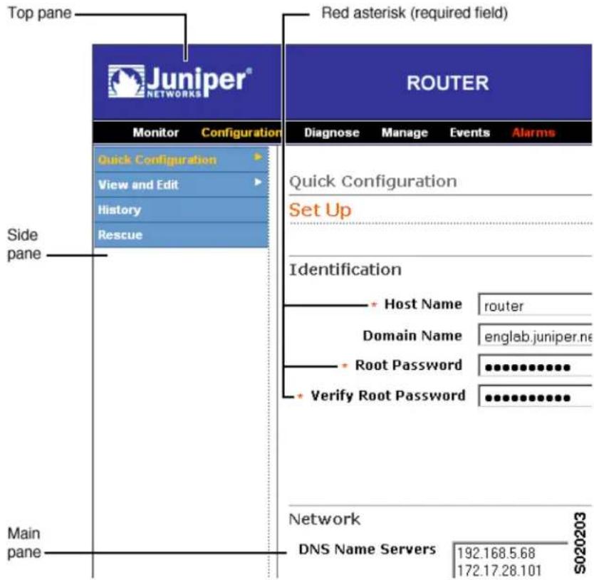
Figure 37: J-Web Layout—Configuration Editor

Table 37: Summary of J-Web Elements
| DescriptionJ-Web Interface Element | |
| Top Pane | |
| Juniper Networks logo | Link to http://www.juniper.net in a new browser window. |
| hostname-model | Hostname and model of the Services Router. |
| Username you used to log in to the Services Router Logged in as: username | |
| Link to context-sensitive help information.Help | |
| Displays information about the J-Web interface, such as the version number.About | |
| Ends your current login session with the Services Router and returns you to the login page.Logout | |
Table 37: Summary of J-Web Elements (continued)
| DescriptionJ-Web Interface Element | |
| Task bar | Menu of J-Web main options. Click to access.■ Monitor—View information about configuration and hardware on the Services Router.■ Configuration—Configure the Services Router with Quick Configuration or the configuration editor, and view configuration history.■ Diagnose—Troubleshoot network connectivity problems.■ Manage—Manage files and licenses, upgrade software, and reboot the Services Router.■ Events—View events and set up filters for an event summary.■ Alarms—View the alarm summary. |
| Main Pane | |
| Help (?) icon | Displays useful information—such as the definition, format, and valid range of an option—when you move the cursor over the question mark. |
| Indicates a required field.Red asterisk (*) | |
| Path of main options and suboptions you selected to display the current main and side panes.Path to current task | |
| Icon Legend | (Applies to the configuration editor only) Explains icons that appear in the user interface to provide information about configuration statements:■ C—Comment. Move your cursor over the icon to view a comment about the configuration statement.■ I—Inactive. The configuration statement does not affect the Services Router.■ M—Modified. The configuration statement is added or modified.■ *—Mandatory. The configuration statement must have a value. |
| Side Pane | |
| Configuration hierarchy | (Applies to the configuration editor only) Displays the hierarchy of committed statements in the Services Router configuration.■ Click Expand all to display the entire hierarchy.■ Click Hide all to display only the statements at the top level.■ Click plus signs (+) to expand individual items.■ Click minus signs (-) to hide individual items. |
J-Web Sessions
You establish a J-Web session with the Services Router through an HTTP-enabled or HTTPS-enabled Web browser. The HTTPS protocol, which uses 128-bit encryption, is available only in domestic versions of the JUNOS software. To use HTTPS, you must have installed a certificate on the Services Router and enabled HTTPS.
When you attempt to log in through the J-Web interface, the Services Router authenticates your username with the same methods used for Telnet and SSH.
The Services Router can support multiple J-Web sessions for a single user who logs in to each session. However, if a single user attempts to launch multiple J-Web windows—for example, by right-clicking a link to launch another instance of a Web browser—the session can have unpredictable results.
If the Services Router does not detect any activity through the J-Web interface for 15 minutes, the session times out and is terminated. You must log in again to begin a new session.
To explicitly terminate a J-Web session at any time, click Logout in the top pane.
Using the Command-Line Interface
This section contains the following topics:
■CLI Command Hierarchy on page 69
■Starting the CLI on page 70
■CLI Operational Mode on page 70
■CLI Configuration Mode on page 71
■CLI Basics on page 72
For more information about the CLI, see the JUNOS CLI User Guide.
CLI Command Hierarchy
The CLI commands are organized hierarchically, with commands that perform a similar function grouped together under the same level. For example, all commands that display information about the Services Router system and system software are grouped under the show command, and all commands that display information about the routing table are grouped under the show route command. Figure 38 illustrates a portion of the show command hierarchy.
Figure 38: CLI Command Hierarchy Example
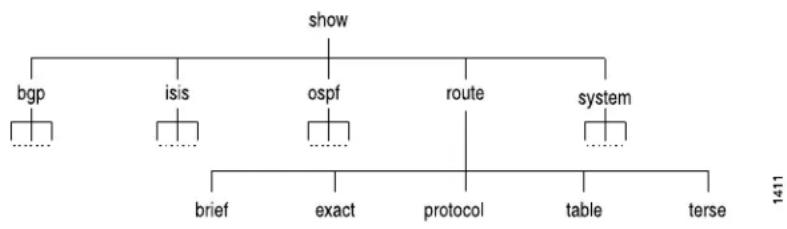
flowchart
graph TD
    A["show"] --> B["bgp"]
    A --> C["isis"]
    A --> D["ospf"]
    A --> E["route"]
    A --> F["system"]
    B --> G["..."]
    C --> H["..."]
    D --> I["..."]
    E --> J["..."]
    F --> K["..."]
    L["brief"] --> M["..."]
    N["exact"] --> O["..."]
    P["protocol"] --> Q["..."]
    R["table"] --> S["..."]
    T["terse"] --> U["..."]
    V["1411"] --> W["..."]
To execute a command, you enter the full command name, starting at the top level of the hierarchy. For example, to display a brief view of the routes in the routing table, use the command show route brief.
The hierarchical organization results in commands that have a regular syntax and provides the following features that simplify CLI use:
- Consistent command names—Commands that provide the same type of function have the same name, regardless of the portion of the software they are operating on. For example, all show commands display software information and statistics, and all clear commands erase various types of system information.
■ Lists and short descriptions of available commands—Information about available commands is provided at each level of the CLI command hierarchy. If you type a question mark (?) at any level, you see a list of the available commands along with a short description of each command.
■ Command completion—Command completion for command names (keywords) and command options is also available at each level of the hierarchy. If you type a partial command name followed immediately by a question mark (with no intervening space), you see a list of commands that match the partial name you typed.
Starting the CLI
To start the CLI:
- Establish a connection with the Services Router:
■To access the router remotely from the network, enter the command you typically use to establish a remote connection (such as Telnet or ssh) using the router hostname.
■To access the router through a management device attached to the console port, start the terminal application.
- Log in using your username and password.
After you log in, you enter a UNIX shell.
- Start the CLI.
user# cli user@host>
The presence of the angle bracket (>) prompt indicates the CLI has started. By default, the prompt is preceded by a string that contains your username and the hostname of the Services Router.
To exit the CLI and return to the UNIX shell, enter the quit command.
CLI Operational Mode
The CLI has two modes: operational and configuration. When you log in to the Services Router and the CLI starts, you are at the top level of operational mode.
To view a list of top-level operational mode commands, type a question mark (?) at the command-line prompt.
| user@host> ? | |
| Possible completions: | |
| clear | Clear information in the system |
| configure | Manipulate software configuration information |
| file | Perform file operations |
| help | Provide help information |
| monitor | Show real-time debugging information |
| mtrace | Trace multicast path from source to receiver |
| ping | Ping remote target |
| quit | Exit the management session |
| request | Make system-level requests |
| restart | Restart software process |
| set | Set CLI properties, date/time, craft interface message |
| show | Show system information |
| ssh | Start secure shell on another host |
| start | Start shell |
| telnet | Telnet to another host |
| test | Perform diagnostic debugging |
| traceroute | Trace route to remote host |
At the top level of operational mode are a number of broad groups of CLI commands that are used to perform the following functions:
■Control the CLI environment.
■Monitor and troubleshoot the router.
■Connect to other systems.
■Manage files and software images.
■Control software processes.
■Stop and reboot the router.
■Enter configuration mode.
To control the CLI environment, see "Configuring the CLI Environment" on page 76. To enter configuration mode, see "CLI Configuration Mode" on page 71. For information about the other CLI operational mode functions, see the J-series Services Router Administration Guide.
CLI Configuration Mode
To configure the Services Router, including system parameters, routing protocols, interfaces, network management, and user access, you must enter configuration mode. In configuration mode, the CLI provides commands to configure the router, load a text (ASCII) file that contains the router configuration, activate a configuration, and save the configuration to a text file.
You enter configuration mode by entering the configure operational mode command. The CLI prompt changes from user@host> to user@host#.
To view a list of configuration mode commands, type a question mark (?) at the command-line prompt. (You do not need to press Enter after typing the question mark.)
user@host# ?
| Possible completions: | |
| Enter | Execute this command |
| activate | Remove the inactive tag from a statement |
| annotate | Annotate the statement with a comment |
| commit | Commit current set of changes |
| copy | Copy a statement |
| deactivate | Add the inactive tag to a statement |
| delete | Delete a data element |
| edit | Edit a sub-element |
| exit | Exit from this level |
| help | Provide help information |
| insert | Insert a new ordered data element |
| load | Load configuration from ASCII file |
| quit | Quit from this level |
| rename | Rename a statement |
| rollback | Roll back to previous committed configuration |
| run | Run an operational-mode command |
| save | Save configuration to ASCII file |
| set | Set a parameter |
| show | Show a parameter |
| status | Show users currently editing configuration |
| top | Exit to top level of configuration |
| up | Exit one level of configuration |
| wildcard | Wildcard operations |
The JUNOS software configuration consists of a hierarchy of statements. There are two types of statements: container statements, which contain other statements, and leaf statements, which do not contain other statements. All the container and leaf statements together form the configuration hierarchy.
Each statement consists of a fixed keyword and, optionally, an identifier that you define, such as the name of an interface or a username.
To configure the Services Router or to modify an existing configuration, you add statements to the configuration with the edit and set configuration mode commands. For more information about the CLI configuration editor and configuration mode, see the J-series Services Router Basic LAN and WAN Access Configuration Guide and the JUNOS software configuration guides.
CLI Basics
This section contains the following topics:
■Editing Keystrokes on page 73
■Command Completion on page 74
■Online Help on page 74
■Configuring the CLI Environment on page 76
Editing Keystrokes
In the CLI, you use keystrokes to move around on and edit the command line, and to scroll through a list of recently executed commands. Table 38 on page 73 lists some typical CLI editing tasks and the keystrokes that perform them.
Table 38: CLI Editing Keystrokes
| Keyboard SequenceActionTask Category | ||
| Ctrl-bMove the cursor back one character.Move the cursor. | ||
| Esc bMove the cursor back one word. | ||
| Ctrl-fMove the cursor forward one character. | ||
| Esc fMove the cursor forward one word. | ||
| Ctrl-eMove the cursor to the end of the command line. | ||
| Ctrl-h, Delete, or BackspaceDelete the character before the command line. | ||
| Ctrl-dDelete the character at the cursor. | ||
| the command line. | Ctrl-kDelete all characters from the cursor to the end of the command line. | |
| Ctrl-u or Ctrl-xDelete all characters on the command line. | ||
| Ctrl-w or Esc BackspaceDelete the word before the command line. | ||
| Esc dDelete the word after the cursor. | ||
| Ctrl-yInsert the most recently deleted text at the command line. | ||
| Ctrl-lRedraw the current line.Redraw the screen. | ||
| Display previous command lines. | commands. | Ctrl-pScroll backward through the list of recently executed lines. |
| commands. | Ctrl-nScroll forward through the list of recently executed lines. | |
| matching the search string. | Ctrl-rSearch the CLI history in reverse order for lines. | |
| prompt, followed by the keyboard sequence. The CLI attempts to expand the text into the most recent word in the history for which the text is a prefix. | Esc /Search the CLI history by typing some text at the CLI. | |
| Repeat keyboard sequences. | Specify the number of times to execute a keyboard sequence. Replace number with a number from 1 through 9, and replace sequence with a keyboard sequence in this table. | Esc number sequence |
Command Completion
You do not always have to remember or type the full command or option name for the CLI to recognize it. To display all possible command or option completions, type the partial command followed immediately by a question mark (?).
To complete a command or option that you have partially typed, press Tab or Spacebar. If the partially typed letters uniquely identify a command, the complete command name appears. Otherwise, a message indicates that your entry is ambiguous or invalid. Possible command completions are displayed if your entry is ambiguous.
You can also use command completion on filenames and usernames. To display all possible values, type one or more characters followed immediately by a question mark. To complete these partial entries, press Tab only. Pressing Spacebar does not work.
Online Help
The CLI provides context-sensitive help at every level of the command hierarchy. The help information tells you which commands are available at the current level in the hierarchy and provides a brief description of each.
To get help while in the CLI, type a question mark (?) in one of the following ways:
■Type a question mark at the command-line prompt. The CLI lists the available commands and options. For examples, see “CLI Operational Mode” on page 70 and “CLI Configuration Mode” on page 71.
■Type a question mark after entering the complete name of a command or command option. The CLI lists the available commands and options, then redispplays the command names and options that you typed:
user@host> request ?
Possible completions:
| chassis | Perform chassis-specific operations |
| ipsec | Perform IP Security operations |
| message | Send text message to other users |
| routing-engine | Log in to Routing Engine |
| security | Perform security-level operations |
| services | Perform service application operations |
| support | Perform JUNOS support tasks |
| system | Perform system-level operations |
| ser@host> request | |
■Type a question mark in the middle of a command name. The CLI lists possible command completions that match the letters you have entered so far, then redispplays the letters that you typed. For example, to list all operational mode commands that start with the letter s, type the following:
user@host> s?
Possible completions:
| set | Set CLI properties, date/time, craft interface |
| message | |
| show | Show system information |
| ssh | Start secure shell on another host |
| start | Start shell |
| user@host> s | |
When you enter the help commands described in Table 39 on page 75, the CLI displays usage guidelines and summary information for configuration statements and operational mode commands. You can enter help commands in operational or configuration mode.
Table 39: help Commands
| DescriptionCLI Command | |
| help apropos string | Displays help based on a text string contained in a statement or command name. |
| If the string contains spaces, enclose it in quotation marks. You also can specify a regular expression for the string, using standard UNIX-style regular expression syntax. | |
| In configuration mode, this command displays statement names and help text that match the string specified. | |
| In operational mode, this command displays the following types of commands that match the string specified, plus help text: | |
| ■ Operational mode commands | |
| ■ help topic and help reference commands you can enter for more information | |
| For example, to get a list of statements that contain the string traps, enter the help apropos traps command in configuration mode. | |
| help reference string | Displays summary information for configuration statements. |
| For example, to display summary information for the OSPF hello interval, enter the command help reference ospf hello-interval. | |
| help topic string | Displays usage guidelines for configuration statements. |
| For example, to display usage guidelines for the OSPF hello interval, enter the command help topic ospf hello-interval. |
Configuring the CLI Environment
You can configure the CLI environment for your current login session. Your settings are not retained when you exit the CLI.
To display the current CLI settings, enter the show cli command:
user@host> show cli
CLI complete-on-space set to on
CLI idle-timeout disabled
CLI restart-on-upgrade set to on
CLI screen-length set to 49
CLI screen-width set to 132
CLI terminal is 'vt100'
CLI is operating in enhanced mode
CLI working directory is '/cf/var/home/remote'
To change the CLI environment, use the set cli operational mode command:
user@host> set cli ?
Possible completions:
complete-on-space Set whether typing space completes current word
directory Set working directory
idle-timeout Set maximum idle time before login session ends
prompt Set CLI command prompt string
restart-on-upgrade Set whether CLI prompts to restart after software upgrade
screen-length Set number of lines on screen
screen-width Set number of characters on a line
terminal Set terminal type
Table 40 on page 76 shows how you can change the CLI environment features.
Table 40: Configuring the CLI Environment
| Feature | OptionsDefault SettingCLI CommandEnvironment | ||
| Command completion | set cli complete-on-space (on | off) | on—Pressing Tab or Spacebar completes a command. | ■ Set off to allow only Tab for command completion.■ Set on to re-enable Tab and Spacebar for command completion. |
| Your working directory | /cf/var/home/remoteset cli directory pathReplace path with the directory you want to enter when you log in to the Services Router. | ||
| Minutes of idle time | set cli idle-time minutes | Your session never times out unless your login class specifies a timeout. | ■ To enable the timeout feature, replace timeout with a value between 1 and 100,000.■ To disable the timeout feature, replace timeout with 0. |
| Your session prompt | set cli prompt string | user@host > | Replace string with the prompt you want. If the prompt contains spaces or special characters, enclose string in quotation marks (““). |
| Restart-after-upgrade prompt | set cli restart-on-upgrade (on | off) | CLI prompts you to restart the Services Router after a software upgrade. | ■ Set off to disable the prompt for the session.■ Set on to reenable the prompt. |
| Number of CLI output line displayed at once | set cli screen-length length | Variable (depends on terminal type). | ■ To change the number of lines displayed on the screen, replace length with a value between 1 and 100,000.■ To disable the display of a set number of lines, replace length with 0. (This feature can be useful when you are issuing CLI commands from scripts.) |
| Number of CLI characters displayed on a line | set cli screen-width width | Variable (depends on terminal type). | To change the number of characters displayed on a line, replace width with a value between 0 and 100,000. |
| Your terminal type. | terminal-type | unknown, or set by console.set cli terminal | ■ ansi■ vt100■ small-xterm■ xterm |
J2300, J4300, and J6300 Services Router Getting Started Guide
Part 2 Installing a Services Router
■Preparing for Router Installation on page 81
■Installing and Connecting a Services Router on page 91
■Establishing Basic Connectivity on page 105
■Configuring Secure Web Access on page 127
■Configuring Autoinstallation on page 137
■Installing and Managing J-series Licenses on page 143
J2300, J4300, and J6300 Services Router Getting Started Guide
Chapter 5
Preparing for Router Installation
Before installing a J-series Services Router, make sure that your site has the proper operating environment and equipment. Use the checklist at the end of the chapter to help you prepare your site.
This chapter discusses the following topics:
■General Site Guidelines on page 81
■Desktop and Wall Mounting Requirements on page 82
■Rack Requirements on page 82
■Router Environmental Tolerances on page 83
■Spacing of Mounting Holes on page 84
■Fire Safety Requirements on page 84
■Power Guidelines, Requirements, and Specifications on page 85
■Network Cable Specifications on page 89
■ISDN Provisioning on page 89
■Site Preparation Checklist on page 90
General Site Guidelines
The following precautions help you plan an acceptable operating environment for your Services Router and avoid environmentally caused equipment failures:
■For the cooling system to function properly, the airflow around the chassis must be unrestricted. Allow at least 6 in. (15.2 cm) of clearance between the front and back of the chassis and adjacent equipment. Ensure that there is adequate circulation in the installation location.
■ Follow ESD procedures described in “Preventing Electrostatic Discharge Damage” on page 209, to avoid damaging equipment. Static discharge can cause components to fail completely or intermittently over time.
■Install blank PIM panels in empty slots, to prevent any interruption or reduction in the flow of air across internal components.
Desktop and Wall Mounting Requirements
The J2300 Services Router can be installed on a desktop or wall. When choosing a location, allow at least 6 in. (15.2 cm) of clearance between the front and back of the chassis and adjacent equipment or walls.
If you are mounting the J2300 router on a wall, use wall screws or wall anchors capable of supporting the full weight of the chassis, up to 12 lb (5.4 kg). If possible, install the wall anchors into wall studs, which provide added support for the chassis.
Rack Requirements
All J-series Services Routers can be installed in a rack. J4300 and J6300 Services Routers must be installed in a rack. Many types of racks are acceptable, including front-mount racks, four-post (telco) racks, and center-mount racks.
The following sections describe rack requirements:
■Rack Size and Strength on page 82
■Connection to Building Structure on page 83
Rack Size and Strength
The Services Router is designed for installation in a rack that complies with either of the following standards:
■A 19-in. rack as defined in Cabinets, Racks, Panels, and Associated Equipment (document number EIA-310-D) published by the Electronics Industry Association (http://www.eia.org)
A 600-mm rack as defined in the four-part Equipment Engineering (EE): European telecommunications standard for equipment practice (document numbers ETS 300 119-1 through 119-4) published by the European Telecommunications Standards Institute (http://www.etsi.org)
The horizontal spacing between the rails in a rack that complies with this standard is usually wider than the router's mounting ears, which measure 19 in. (48.2 cm) from outer edge to outer edge. Use approved wing devices to narrow the opening between the rails as required.
The rack rails must be spaced widely enough to accommodate the router chassis's external dimensions
■A J2300 chassis is 1.75 in. (4.4 cm) high, 17.25 in. (43.8 cm) wide, and 12.37 in. (31.4 cm) deep.
■A J4300 or J6300 chassis is 3.5 in. (8.9 cm) high, 17 in. (43.2 cm) wide, and 19 in. (48.3 cm) deep.
The outer edges of the mounting ears extend the width of either chassis to 19 in. (48.2 cm), and the front of the chassis extends approximately 0.5 in. (1.27 cm)
beyond the mounting ears. The spacing of rails and adjacent racks must also allow for the clearances around the router and rack. (See “General Site Guidelines” on page 81.)

CAUTION: If you are mounting the router in a cabinet, be sure that ventilation is sufficient to prevent overheating.
If a front-mount rack is used, we recommend supporting the back of the router with a shelf or other structure.
The J2300 chassis height of 1.75 in. (4.4 cm) equals 1 U. The J4300 and J6300 chassis height of 3.5 in. (8.7 cm) equals 2 U. Each U is a standard rack unit defined in Cabinets, Racks, Panels, and Associated Equipment (document number EIA-310-D) published by the Electronics Industry Association.
Connection to Building Structure
Always secure the rack to the structure of the building. If your geographical area is subject to earthquakes, bolt the rack to the floor. For maximum stability, also secure the rack to ceiling brackets. For more information, see “Rack-Mounting Requirements and Warnings” on page 226.
Router Environmental Tolerances
Table 41 on page 83 specifies the environmental conditions required for normal Services Router operation. In addition, the site must be as dust-free as possible. Dust can clog air intake vents, reducing cooling system efficiency. Check vents frequently, cleaning them as necessary.
Table 41: Router Environmental Tolerances
| ValueDescription | |
| No performance degradation to 10,000 ft (3048 m)Altitude | |
| Relative humidity | Normal operation ensured in relative humidity range of 5% to 90%, noncondensing |
| Temperature | Normal operation ensured in temperature range of 0°C (32°F) to 40°C (104°F)Non-operating storage temperature in shipping carton: 40°C (-40°F) to 70°C (158°F) |
| Seismic | Designed to meet Telcordia Technologies Zone 4 earthquake requirements |
| ValueDescription | |
| Maximum thermal output | J2300 chassis |
| ■ Typical—270 BTU/hour (80 W) | |
| ■ Maximum—750 BTU/hour (220 W) | |
| J4300 and J6300 chassis | |
| ■ Typical—510 BTU/hour (150 W) | |
| ■ Maximum—1190 BTU/hour (350 W) | |
Spacing of Mounting Holes
The mounting holes in the mounting brackets provided with the J2300 Services Router chassis are spaced 1.25 in. (3.2 cm) apart, measured from the center of the hole.
The mounting holes in the mounting brackets attached to the J4300 and J6300 chassis are spaced in two groups. The space between the holes in each group is 0.6 in. (1.5 cm) apart, measured from the center of each hole. The space between the two groups is 1.75 (4.4 cm) apart, measured from the center of the lower hole in the top group to the upper hole in the bottom group.
Fire Safety Requirements
In the event of a fire emergency involving Services Routers and other network equipment, the safety of people is the primary concern. Establish procedures for protecting people in the event of a fire emergency, provide safety training, and properly provision fire-control equipment and fire extinguishers.
In addition, establish procedures to protect your equipment in the event of a fire emergency. Juniper Networks products must be installed in an environment suitable for electronic equipment. We recommend that fire suppression equipment be available in the event of a fire in the vicinity of the equipment, and that all local fire, safety, and electrical codes and ordinances be observed when you are installing and operating your equipment.
Fire Suppression
In the event of an electrical hazard or an electrical fire, first unplug the power cord. (For shutdown instructions, see “Powering a Services Router On and Off” on page 104.)
Then, use a Type C fire extinguisher, which uses noncorrosive fire retardants, to extinguish the fire. For more information about fire extinguishers, see “Fire Suppression Equipment” on page 85.
Fire Suppression Equipment
Type C fire extinguishers, which use noncorrosive fire retardants such as carbon dioxide (CO_2) and Halotron, are most effective for suppressing electrical fires. Type C fire extinguishers displace the oxygen from the point of combustion to eliminate the fire. For extinguishing fire on or around equipment that draws air from the environment for cooling, use this type of inert oxygen displacement extinguisher instead of an extinguisher that leave residues on equipment.
Do not use multipurpose Type ABC chemical fire extinguishers (dry chemical fire extinguishers) near Juniper Networks equipment. The primary ingredient in these fire extinguishers is monoammonium phosphate, which is very sticky and difficult to clean. In addition, in minute amounts of moisture, monoammonium phosphate can become highly corrosive and corrodes most metals.

NOTE: To keep warranties effective, do not use a dry chemical fire extinguisher to control a fire at or near a Juniper Networks router. If a dry chemical fire extinguisher is used, the unit is no longer eligible for coverage under a service agreement.
Any equipment in a room in which a chemical fire extinguisher has been discharged is subject to premature failure and unreliable operation. The equipment is considered to be irreparably damaged.
We recommend that you dispose of any irreparably damaged equipment in an environmentally responsible manner.
Power Guidelines, Requirements, and Specifications
All Services Routers are available with either AC or DC power. For information about each router's power system, see "J2300 Power System" on page 19, "J4300 Power System" on page 29, and "J6300 Power System" on page 29.
For site wiring and power system guidelines, requirements, and specifications, see the following sections:
■Site Electrical Wiring Guidelines on page 85
■Router Power Requirements on page 86
■AC Power, Connection, and Power Cord Specifications on page 87
■DC Power, Connection, and Power Cable Specifications on page 88
Site Electrical Wiring Guidelines

WARNING: DC-powered J2300 Services Routers are intended for installation in a dedicated equipment room where they are accessible by trained personnel only. DC-powered J4300 and J6300 Services Routers are intended for installation only in a restricted access location.
When planning the electrical wiring at your site, consider the factors discussed in the following sections.
Signaling Limitations
Improperly installed wires can emit radio interference. In addition, the potential for damage from lightning strikes increases if wires exceed recommended distances, or if wires pass between buildings. The electromagnetic pulse (EMP) caused by lightning can damage unshielded conductors and destroy electronic devices. If your site has previously experienced such problems, you might want to consult experts in electrical surge suppression and shielding.
Radio Frequency Interference
You can reduce or eliminate the emission of radio frequency interference (RFI) from your site wiring by using twisted-pair cable with a good distribution of grounding conductors. If you must exceed the recommended distances, use a high-quality twisted-pair cable with one ground conductor for each data signal when applicable.
Electromagnetic Compatibility
If your site is susceptible to problems with electromagnetic compatibility (EMC), particularly from lightning or radio transmitters, you might want to seek expert advice. Strong sources of electromagnetic interference (EMI) can destroy the signal drivers and receivers in the router and conduct power surges over the lines into the equipment, resulting in an electrical hazard. It is particularly important to provide a properly grounded and shielded environment and to use electrical surge-suppression devices.

CAUTION: To comply with intrabuilding lightning/surge requirements, intrabuilding wiring must be shielded, and the shield for the wiring must be grounded at both ends.
Router Power Requirements
Table 42 on page 86 lists the AC and DC power system electrical specifications for J-series Services Routers.
Table 42: AC and DC Power System Electrical Specifications
| SpecificationItem | |
| AC input voltage | 100 to 240 VAC nominal |
| 100 to 264 VAC operating range (J2300, J4300, and J6300 Services Routers) | |
| AC input line frequency | 47 to 63 Hz (J2300, J4300, and J6300 Services Routers) |
| 50 to 60 Hz (J4350 and J6350 Services Routers) | |
| AC system current rating | 4 to 2 A (J2300 Services Router) |
| 6 to 3 A (J4300 and J6300 Services Routers) | |
| 6 A (J4350 Services Router) | |
| 8 A (J6350 Services Router) | |
| DC input voltage | -42 to -72 VDC operating range (J2300, J4300, and J6300 Services Routers) |
| -48 to ~60 VDC operating range (J4350 and J6350 Services Routers) | |
| DC system current rating | 4 A @ -48 VDC (nominal, J2300 Services Router) |
| 8 A @ -48 VDC (nominal, J4300 and J6300 Services Routers) | |
| 20 A ((J4350 and J6350 Services Routers) |
AC Power, Connection, and Power Cord Specifications

NOTE: The AC power cord for the Services Router is intended for use with the router only and not for any other use.
Detachable AC power cords, each 2.5 m (approximately 8 ft) long, are supplied with the Services Router. The appliance coupler at the female end of the cord inserts into the appliance inlet on the faceplate of the AC power supply. The coupler is type C19 as described by International Electrotechnical Commission (IEC) standard 60320. The plug at the male end of the power cord fits into the power source receptacle that is standard for your geographical location.

NOTE: In North America, AC power cords must not exceed 4.5 m (approximately 14.75 ft) in. length, to comply with National Electrical Code (NEC) Sections 400-8 (NFPA 75, 5-2.2) and 210-52, and Canadian Electrical Code (CEC) Section 4-010(3). The cords supplied with the router are in compliance.
Table 43 on page 87 lists AC power cord specifications provided for each country or region.
Table 43: AC Power Cord Specifications
| Plug StandardsElectrical SpecificationsCountry |
| AS/NZ 3112-1993250 VAC, 10 A, 50 HzAustralia |
| GB2099.1 1996 and GB1002 1996 (CH1-10P)250 VAC, 10 A, 50 HzChi |
Table 43: AC Power Cord Specifications (continued)
| Plug StandardsElectrical SpecificationsCountry | |
| United Kingdom) | CEE (7) VII250 VAC, 10 A, 50 HzEurope (except Italy and |
| CEI 23-16/VII250 VAC, 10 A, 50 HzItaly | |
| JIS 8303125 VAC, 12 A, 50 Hz or 60 HzJapan | |
| NEMA 5-15125 VAC, 10 A, 60 HzNorth America | |
| BS 1363A250 VAC, 10 A, 50 HzUnited Kingdom |
Figure 39 illustrates the plug on the power cord for each country or region listed in Table 43 on page 87.
Figure 39: AC Plug Types


NOTE: Power cords and cables must not block access to router components or drape where people might trip on them.
For information about the AC power supply, see "J2300 Power System" on page 19, "J4300 Power System" on page 29, or "J6300 Power System" on page 29.
To connect the power cord during initial installation, see "Connecting Power" on page 98.
To replace the AC power cord, see "Replacing an AC Power Supply Cord" on page 171.
DC Power, Connection, and Power Cable Specifications
Each DC power supply has a single DC input (-48 VDC and return) that requires a dedicated 15 A (-48 VDC) circuit breaker. If the J6300 router contains redundant DC power supplies, one power supply must be powered by a dedicated power feed derived from feed A, and the other power supply must be powered by a dedicated power feed derived from feed B. This configuration provides the commonly deployed A/B feed redundancy for the system.
Most sites distribute DC power through a main conduit that leads to frame-mounted DC power distribution panels, one of which might be located at the top of the rack that houses the router. A pair of cables (one input and one return) connects each set of terminal studs to the power distribution panel.

CAUTION: There is no standard color coding for DC power cables. The color coding used by the external DC power source at your site determines the color coding for the leads on the power cables that attach to the terminal studs on each power supply. You must ensure that power connections maintain the proper polarity. The power source cables might be labeled (+) and (−) to indicate their polarity.

WARNING: Power plant ground and chassis ground must be connected to the same building ground.

CAUTION: Before router installation begins, a licensed electrician must attach a cable lug to the grounding and power cables that you supply. A cable with an incorrectly attached lug can damage the router (for example, by causing a short circuit).
Each DC power cable (-48 VDC and return) must be 14 AWG single-strand wire cable, or as permitted by the local code. Each lug attached to the power cables must be a ring-type, vinyl-insulated TV14-6R lug, or equivalent.

NOTE: Power cords and cables must not block access to router components or drape where people might trip on them.
For information about the DC power supply, see "J2300 Power System" on page 19, "J4300 Power System" on page 29, or "J6300 Power System" on page 29.
To connect the DC power cable during initial installation, see “Connecting DC Power” on page 100.
To replace a DC power cable, see "Replacing a DC Power Supply Cable" on page 174.
Network Cable Specifications
The Services Router supports interfaces that use various kinds of network cable. For information about the type of cable used by each interface, see “Network Cable Specifications and Connector Pinouts” on page 189.
ISDN Provisioning
You might need a network termination type 1 (NT1) device to connect your ISDN interface to the ISDN service. Contact your service provider for details on the following information:
■External NT1 device and ISDN cable
■If the two items are required, where to obtain the items
■List of NT1 vendors
Site Preparation Checklist
The checklist in Table 44 on page 90 summarizes the tasks you need to perform when preparing a site for Services Router installation.
Table 44: Site Preparation Checklist
| NotesDatePerformed ByItem or Task | |
| Verify that environmental factors such as temperature and humidity do not exceed router tolerances. | |
| Measure the distances between external power sources and the router installation site. | |
| Select the type of rack. | |
| Plan the rack location, including required space clearances. | |
| Secure the rack to the floor and the building structure. | |
| Acquire appropriate cables and connectors. |
Chapter 6
Installing and Connecting a Services Router
Make the appropriate preparations and verify the J-series equipment before installing a J-series Services Router and connecting it to a power source and the network.
This chapter contains the following topics:
■Before You Begin on page 91
■Unpacking a J-series Services Router on page 92
■Installing the J2300 Services Router on page 93
■Installing the J4300 or J6300 Services Router on page 96
■Connecting Interface Cables to a Services Router on page 97
■Chassis Grounding on page 98
■Connecting Power on page 98
■Powering a Services Router On and Off on page 104
Before You Begin
Before you begin installation, complete the following tasks:
- Read the information in “Maintenance and Operational Safety Guidelines and Warnings” on page 236, with particular attention to “Chassis Lifting Guidelines” on page 225.
■Determine where to install the Services Router, and verify that the rack or installation site meets the requirements described in “Preparing for Router Installation” on page 81.
■ For installation, gather the equipment and tools listed in Table 45 on page 92.
Table 45: Equipment and Tools Required for Services Router Installation
| DeskInstallation—J2300Services Router Only | Rack InstallationWall Installation—J2300 Services Router C | |
| Rubber feet (provided) | Rubber feet (provided)Mounting brackets and screws (provided)Number 2 Phillips screwdriverFour wall screws or four mounting screws and anchors capable of supporting the full weight of the chassis, up to 12 lb (5.4 kg) | Mounting brackets and screws (provided)Number 2 Phillips screwdriverFour (J2300) or eight (J4300 and J6300) mounting screws appropriate for your rack |
| ■For installation, gather the following equipment and tools: mounting brackets and screws (provided), number 2 Phillips screwdriver, and mounting screws appropriate for your rack.■To connect the router to power and ground, have ready a 14 AWG grounding cable and lug, as specified in “Chassis Grounding” on page 98, and the power cords or cords shipped with the router. (You must supply your own power cables if you have a DC-powered router.) | ||
| NOTE:The AC power cord for the Services Router is intended for use with the router only and not for any other use. | ||
| ■ To connect network interfaces, have ready a length of cable used by the interface, as specified in “Network Cable Specifications and Connector Pinouts” on page 189.■If your router has ISDN ports, you might need an NT1 device to connect to the ISDN service. For details, see “ISDN Provisioning” on page 89. | ||
Unpacking a J-series Services Router
The Services Router is shipped in a cardboard carton and secured with foam packing material. The carton also contains an accessory box and quick start instructions.

NOTE: The router is maximally protected inside the shipping carton. Do not unpack it until you are ready to begin installation.
To unpack the router:
- Move the shipping carton to a staging area as close to the installation site as possible, but where you have enough room to remove the router.
- Position the carton so that the arrows are pointing up.
- Open the top flaps on the shipping carton.
- Remove the accessory box, and verify the contents against the parts inventory on the label attached to the carton.
- Pull out the packing material holding the router in place.
- Verify the contents of the carton against the packing list included with the router.
- Save the shipping carton and packing materials in case you later need to move or ship the router.
Installing the J2300 Services Router

WARNING: DC-powered J2300 Services Routers are intended for installation in a dedicated equipment room where they are accessible by trained personnel only.
You can install the J2300 Services Router on a desk, on a wall, or in a rack. The J2300 Services Router includes mounting brackets that support either wall or rack mounting, and rubber feet for desk and wall mounting.
Install the J2300 Services Router as appropriate for your site, with one of the following procedures:
■Installing the J2300 Services Router on a Desk on page 93
■Installing the J2300 Services Router on a Wall on page 94
■Installing the J2300 Services Router into a Rack on page 95
Installing the J2300 Services Router on a Desk
You can install the J2300 Services Router on a desk, table, or other level surface. The router is shipped with rubber feet in the accessory box. The rubber feet are necessary to stabilize the router on the desk.
To install the J2300 router on a desk:
- Turn the chassis upside-down on the desk or work surface where you intend to operate the router.
- Attach the provided rubber feet to the bottom of the chassis, as shown in Figure 40.
- Turn the chassis right-side up on the desk or work surface.
Figure 40: Attaching Rubber Feet to the J2300 Services Router

Installing the J2300 Services Router on a Wall
You can install the J2300 Services Router on a wall. The router is shipped with mounting brackets and rubber feet in the accessory box. The rubber feet help stabilize the router on the wall and enhance airflow.
To install the J2300 router on a wall:
- Turn the chassis upside-down on a desk or work surface near where you intend to operate the router.
- Attach the provided rubber feet to the bottom of the chassis, as shown in Figure 40.
- Turn the chassis right-side up, and place it on a flat surface.
- Position a mounting bracket on each side of the chassis as shown in Figure 41.
- Use a number 2 Phillips screwdriver to install the screws that secure the mounting brackets to the chassis.
- If you are using wall anchors to support the chassis, install two pairs of anchors on the wall, spaced 19 in. (48.3 cm) apart.

CAUTION: Mounting screws and wall anchors must be strong enough to support the full weight of the chassis, up to 12 lb (5.4 kg). Attaching the router to wall studs or using wall anchors provides extra support for the chassis.
- Have one person grasp the sides of the router, lift the router, and position it on the wall.
- Have a second person install two pairs of mounting screws through the bracket holes on either side of the router, to secure the router to the wall.
- Verify that the mounting screws on one side are aligned with the mounting screws on the opposite side and that the router is level.
Figure 41: Attaching Mounting Brackets to Install a J2300 Services Router on a Wall

Installing the J2300 Services Router into a Rack
You can front-mount the J2300 Services Router in a rack. The router is shipped with mounting brackets in the accessory box. Many types of racks are acceptable, including four-post (telco) racks, enclosed cabinets, and open-frame racks. For more information about the type of rack or cabinet the J-series router can be installed into, see "Rack Requirements" on page 82.

NOTE: If you are installing multiple routers in one rack, install the lowest one first and proceed upward in the rack.

NOTE: The chassis weighs up to 12 lb (5.4 kg). Have one person lift the chassis into the rack and a second person secure the mounting screws.
To install the J2300 router into a rack:
- Position a mounting bracket on each side of the chassis as shown in Figure 42.
- Use a number 2 Phillips screwdriver to install the screws that secure the mounting brackets to the chassis.
- Have one person grasp the sides of the router, lift the router, and position it in the rack.
- Align the bottom hole in each mounting bracket with a hole in each rack rail, making sure the chassis is level.
- Have a second person install a mounting screw into each of the two aligned holes. Use a number 2 Phillips screwdriver to tighten the screws.
- Install the second screw in each mounting bracket.
- Verify that the mounting screws on one side of the rack are aligned with the mounting screws on the opposite side and that the router is level.
Figure 42: Attaching Mounting Brackets to Install a J2300 Services Router in a Rack

Installing the J4300 or J6300 Services Router

WARNING: DC-powered Services Routers are intended for installation only in a restricted access location.
You can front-mount the J4300 or J6300 Services Router in a rack. Many types of racks are acceptable, including four-post (telco) racks, enclosed cabinets, and open-frame racks. For more information about the type of rack or cabinet the J-series router can be installed into, see "Rack Requirements" on page 82.

WARNING: If you are installing multiple routers in one rack, install the lowest one first and proceed upward in the rack. Install heavier routers in the lower part of the rack. The router should be mounted at the bottom of the rack if it is the only unit in the rack.

NOTE: The chassis weighs between 18 lb (8 kg) and 31 lb (14 kg). Have one person lift the chassis into the rack and a second person secure the mounting screws.
To install the J4300 or J6300 router into a rack:
- Have one person grasp the sides of the router, lift the router, and position it in the rack.
- Align the bottom hole in each mounting bracket with a hole in each rack rail as shown in Figure 43, making sure the chassis is level.
- Have a second person install a mounting screw into each of the two aligned holes. Use a number 2 Phillips screwdriver to tighten the screws.
- Install the remaining screws in each mounting bracket.
- Verify that the mounting screws on one side of the rack are aligned with the mounting screws on the opposite side and that the router is level.
Figure 43: Installing the J4300 or J6300 Services Router

Connecting Interface Cables to a Services Router
You connect the interfaces installed in the Services Router to various network media. For more information about the network interfaces supported on the router, see the J-series Services Router Basic LAN and WAN Access Configuration Guide.
- Have ready a length of the type of cable used by the interface, as specified in "Network Cable Specifications and Connector Pinouts" on page 189.
- Insert the cable connector into the cable connector port on the interface faceplate.
- Arrange the cable as follows to prevent it from dislodging or developing stress points:
a. Secure the cable so that it is not supporting its own weight as it hangs to the floor.
b. Place excess cable out of the way in a neatly coiled loop.
c. Place fasteners on the loop to help maintain its shape.
Chassis Grounding
To meet safety and electromagnetic interference (EMI) requirements and to ensure proper operation, the Services Router must be adequately grounded before power is connected. In addition to the grounding pin on the AC power plug cord, a threaded insert (PEM nut), screw, and washer are provided on the rear of the chassis to connect the router to earth ground.

CAUTION: Before router installation begins, a licensed electrician must attach a cable lug to the grounding and power cables that you supply. A cable with an incorrectly attached lug can damage the router (for example, by causing a short circuit).
The grounding cables must be 14 AWG single-strand wire cable, and must be able to handle the following amperage:
■J2300 router—up to 4 A
■J4300 router and J6300 router—up to 8 A
Each grounding lug must be a ring-type, vinyl-insulated TV14-6R lug, or equivalent, to accommodate the 14 AWG cable.
To ground the router before connecting power, you connect the grounding cable to earth ground and then attach the lug on the cable to the chassis grounding point, with the screw. (See "Connecting Power" on page 98.)
Connecting Power
J2300 or J4300 Services Routers have a single fixed power supply. J6300 Services Routers have one or two field-replaceable power supplies. For more information about the J-series power specifications, see “Power Guidelines, Requirements, and Specifications” on page 85.

WARNING: DC-powered J2300 Services Routers are intended for installation in a dedicated equipment room where they are accessible by trained personnel only. DC-powered Services Routers are intended for installation only in a restricted access location.
Connecting AC Power
The router must be connected to earth ground during normal operation. The protective earthing terminal on the rear of the chassis is provided to connect the router to ground. Additional grounding is provided to an AC-powered router when you plug its power supply into a grounded AC power receptacle.
The AC power cord shipped with the router connects the router to earth ground when plugged into an AC grounding-type power outlet. The router must be connected to earth ground during normal operation.
For power cord requirements, see "AC Power, Connection, and Power Cord Specifications" on page 87
To connect AC power to the router:
-
Attach an electrostatic discharge (ESD) grounding strap to your bare wrist, and connect the strip to the ESD point on the chassis. For more information about ESD, see "Preventing Electrostatic Discharge Damage" on page 209.
-
Use a grounding cable to connect the router to earth ground: (For cable requirements, see "Chassis Grounding" on page 98.)
a. Verify that a licensed electrician has attached an appropriate grounding cable lug to the grounding cable.
b. Connect one end of the grounding cable to a proper earth ground, such as the rack in which the router is installed.
c. With a Phillips screwdriver, remove the screw and washer from the PEM nut at the grounding point on the rear of the chassis.
d. Place the grounding lug at the other end of the cable over the grounding point, as shown in Figure 44, Figure 45, and Figure 46.
e. Secure the cable lug to the grounding point, first with the washer, then with the screw.
-
Locate the power cord or cords shipped with the router, which has a plug appropriate for your geographical location. For power cord specifications, see "Power Guidelines, Requirements, and Specifications" on page 85.
-
For each power supply:
a. Insert the appliance coupler end of a power cord into the appliance inlet on the power supply faceplate, as shown in Figure 44, Figure 45, and Figure 46.
b. Insert the plug into an AC power source receptacle.
- Verify that the power cord does not block access to router components or drape where people can trip on it.
Figure 44: Connecting AC Power to the J2300 Services Router

Figure 45: Connecting AC Power to the J4300 Services Router

Figure 46: Connecting AC Power to the J6300 Services Router
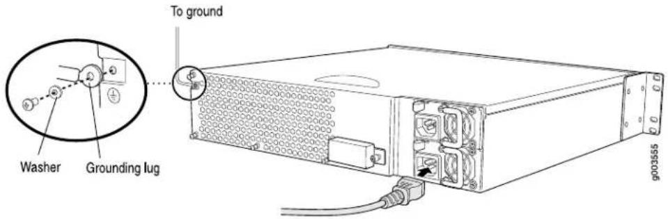
Connecting DC Power

CAUTION: If your J6300 Services Router includes an optional redundant DC power supply, connect each of the two power supplies to different input power sources. Failure to do so makes the router susceptible to total power failure if one of the power supplies fails.
The router must be connected to earth ground during normal operation. The protective earthing terminal on the rear of the chassis is provided to connect the router to ground.
For DC cable requirements, see "DC Power, Connection, and Power Cable Specifications" on page 88.
To connect DC power to the router:
-
Attach an electrostatic discharge (ESD) grounding strap to your bare wrist, and connect the strip to the ESD point on the chassis. For more information about ESD, see "Preventing Electrostatic Discharge Damage" on page 209.
-
Use a grounding cable to connect the router to earth ground: (For cable requirements, see "Chassis Grounding" on page 98.)
a. Verify that a licensed electrician has attached an appropriate grounding cable lug to the grounding cable.
b. Connect one end of the grounding cable to a proper earth ground, such as the rack in which the router is installed.
c. With a Phillips screwdriver, remove the screw and washer from the PEM nut at the grounding point on the rear of the chassis.
d. Place the grounding lug at the other end of the cable over the grounding point, as shown in Figure 47, Figure 48, and Figure 49.
e. Secure the cable lug to the grounding point, first with the washer, then with the screw.

NOTE: A DC power supply in a Services Router becomes grounded when you connect a grounding cable between the router and earth ground.
- For each power supply:
a. Ensure that the voltage across the DC power source cable leads is 0 V and that there is no chance that the cable leads might become active during installation.

CAUTION: There is no standard color coding for DC power cables. The color coding used by the external DC power source at your site determines the color coding for the leads on the power cables that attach to the terminal studs on each power supply. You must ensure that power connections maintain the proper polarity. The power source cables might be labeled (+) and (−) to indicate their polarity.
b. Verify that a licensed electrician has attached the appropriate power cable lugs to the negative and positive DC source power cables.
c. Use a Phillips screwdriver to remove the clear plastic cover protecting the terminal block.
d. Within the terminal block, remove the two center screws next to the labels -48 VDC and RTN.
Each screw contains a captive washer to secure a DC source power cable lug to the terminal block.
e. Using one of the removed screws, secure the positive (+) DC source power cable lug to the RTN terminal. Tighten the screw until snug. Do not overtighten. Apply between 8 lb-in. (0.9 Nm) and 9 lb-in. (1.02 Nm) of torque to the screw.
f. Using the other removed screw, secure the negative (−) DC source power cable lug to the -48 VDC terminal. Tighten the screw until snug. Do not overtighten. Apply between 8 lb-in. (0.9 Nm) and 9 lb-in. (1.02 Nm) of torque to the screw.
g. Dress the power cables appropriately.
h. Replace the clear plastic cover over the terminal block.
- Verify that the power cables do not block access to router components or drape where people can trip on them.
Figure 47: Connecting DC Power to the J2300 Services Router

Figure 48: Connecting DC Power to the J4300 Services Router

Figure 49: Connecting DC Power to the J6300 Services Router

Powering a Services Router On and Off
To power on a Services Router, press the power button. The Routing Engine boots as the power supply completes its startup sequence. The POWER LED lights during startup and remains on steadily when the router is operating normally.
To power off a Services Router, you can shut it down in one of the following ways:
■ Graceful shutdown—Press and release the power button. The router begins gracefully shutting down the operating system and then powers itself off.
- Immediate shutdown—Press the power button and hold it for more than 5 seconds. The router immediately powers itself off without shutting down the operating system.
To remove power completely from the router, unplug the AC power cord or switch off the DC power source. The power button on the Services Router is a standby power switch. If the router is connected to a power source when you press the power button to power the router off, the router remains in standby mode and a small amount (5 V and 3.3 V) of standby voltage is still available in the chassis.
Chapter 7
Establishing Basic Connectivity
The JUNOS software is preinstalled on the Services Router. When the router is powered on, it is ready to be configured. If the router does not have a configuration from the factory or your service provider, you must configure the software to establish basic connectivity.
If you are setting up a Services Router for the first time, you can use either J-Web Quick Configuration or a configuration editor to configure basic connectivity. For a brief explanation of J-Web Quick Configuration and the J-Web and CLI configuration editors, see “Services Router User Interface Overview” on page 61.
If you are setting up many Services Routers, autoinstallation can help automate the configuration process. For more information about autoinstallation, see “Configuring Autoinstallation” on page 137.
This chapter contains the following topics. For more information about basic connectivity, see the JUNOS System Basics Configuration Guide.
■Basic Connectivity Terms on page 105
■Basic Connectivity Overview on page 106
■Before You Begin on page 110
■Connecting to a Services Router on page 111
■ Configuring Basic Settings with J-Web Quick Configuration on page 118
■ Configuring Basic Settings with a Configuration Editor on page 120
■Verifying Basic Connectivity on page 124
Basic Connectivity Terms
Before configuring basic connectivity, become familiar with the terms defined in Table 46 on page 105.
Table 46: Basic Connectivity Terms
| DefinitionTerm |
| Name that identifies the network or subnetwork of a router.domain name |
Table 46: Basic Connectivity Terms (continued)
| DefinitionTerm | |
| Dynamic Host Configuration Protocol (DHCP) | Protocol for assigning dynamic IP addresses to devices on a network. |
| gateway | Packets destined for IP addresses not identified in the routing table are sent to the default gateway. |
| Unique name that identifies a router on the network.hostname | |
| loopback address | IP address of a Services Router on logical interface lo0.0 that is always active and available to external hosts and as the source address for outgoing packets. |
| Network Time Protocol (NTP) | Protocol that provides a reliable way of synchronizing the system time of a router. |
| root user | A superuser or system administrator who can perform any task in the file system. |
| secure shell (SSH) | Protocol that provides a secured method of logging in to a remote network system. |
| Telnet | Software that allows a computer to act as a remote terminal on a network system. |
Basic Connectivity Overview
To connect your Services Router to the network and establish basic connectivity, you enter information about your network. This overview contains the following topics:
■Router Identification on page 106
■Root Password on page 107
■Time Zone and System Time on page 107
■Network Settings on page 108
■Default Gateway on page 108
■Backup Router on page 108
■Loopback Address on page 108
■ Built-In Ethernet Interface Address on page 109
■Management Access on page 109
Router Identification
The domain name defines the network or subnetwork that the Services Router belongs to. The hostname refers to the specific machine, while the domain name is shared
among all the devices in a given network. Together the hostname and domain name identify the router in the network.
Root Password
The root user has complete privileges to configure the Services Router, and manage files in the router's file system. Initially, the root password is not defined on the router. To ensure basic security, you must define the root password during initial configuration. If a root password is not defined, you cannot commit configuration settings to take effect on the router.
If you use a plain-text password, the router displays the password as an encrypted string so that users viewing the configuration cannot easily see the password.
The root password must meet the following conditions:
■The password must be at least 6 characters long.
■You can include most character classes in a password (alphabetic, numeric, and special characters), except control characters.
- Valid passwords must contain at least one change of case or character class.
For Common Criteria environments only, the password must be between 10 and 20 characters long and must include at least three of the five character classes (uppercase letters, lowercase letters, punctuation marks, numbers, and other special characters). Control characters are not recommended. For more information, see the Secure Configuration Guide for Common Criteria and JUNOS-FIPS.
Time Zone and System Time
You define the time zone for the location where you plan to operate the Services Router by using a designation that consists of the following information for the location:
■ Name of the continent or ocean—For example, America or Atlantic
■ Name of the major city or other geographic feature in the time zone—For example, Detroit or Azores
A Network Time Protocol (NTP) server provides accurate time across a network. The router synchronizes the system time with the NTP server, and periodically accesses the NTP server to maintain the correct time.
The time zone and system time must be accurate so that the router schedules events and operations as expected.
For Common Criteria compliance, you must configure NTP to provide accurate timestamps for system log messages. For more information, see the Secure Configuration Guide for Common Criteria and JUNOS-FIPS.
Network Settings
A Domain Name System (DNS) server on the network maintains a database for resolving hostnames and IP addresses. Network devices can query the DNS server by hostnames rather than IP addresses. The router accesses the DNS servers that are added to the configuration to resolve hostnames in the order in which you list them.
If you plan to include your router in several domains, you can add these domains to the configuration so that they are included in a DNS search. When DNS searches are requested, the domain suffixes are appended to the hostnames.
Default Gateway
A default gateway is a static route that is used to direct packets addressed to networks not explicitly listed in the routing table. If a packet arrives at the Services Router with an address that the router does not have routing information for, the router sends the packet to the default gateway. The default gateway entry is always present in the routing and forwarding tables.
Backup Router
You can specify a backup router to take over when the routing protocol process of the Services Router is not running, usually when the Services Router is booting, or if its routing protocol process has failed. Packets arriving at a Services Router in this situation are routed to the backup router. When the routing protocol process starts up again, the address of the backup router is removed from the routing and forwarding tables of the Services Router. The backup router must be located on the same subnet.

NOTE: To configure a backup router, you must use the CLI or J-Web configuration editor. You cannot configure a backup router with J-Web Quick Configuration.
Loopback Address
The loopback address is the IP address of the Services Router. The loopback address ensures that the Services Router provides an IP address to management applications. Because it must always be available to hosts attempting to route packets to the Services Router, the loopback address resides on an interface that is always active, known as the loopback interface (lo0.0). Setting a loopback address ensures that the Services Router can receive packets addressed to the loopback address as long as the router is reachable though any entry (ingress) interface. In addition, applications such as NTP, RADIUS, and TACACS + can use the loopback address as the source address for outgoing packets.
If you use the J-Web Set Up Quick Configuration page, you can either set a loopback address of your choice or have the loopback address automatically set to 127.0.0.1 when you click Apply or OK to commit the configuration.
Built-In Ethernet Interface Address
The built-in Fast Ethernet interfaces, fe-0/0/0 and fe-0/0/1, on the front panel of the Services Router, are the interfaces through which you perform initial router setup. The examples in this guide use the fe-0/0/0 interface as the management interface, but you can use any built-in Ethernet port for management. After the initial configuration is complete, you can attach the built-in Ethernet port that you are using for management purposes to the management network.
Before initial configuration, when the factory default configuration is active, the Services Router attempts to perform autoinstallation by obtaining a router configuration through all its connected interfaces, including fe-0/0/0. The Services Router acts as a DHCP client out the built-in Ethernet interfaces.
If the Services Router does not find a DHCP server within a few seconds, it sets the address of fe-0/0/0 to 192.168.1.1/24 and becomes a DHCP server out the fe-0/0/0 interface.

NOTE: If the fe-0/0/1 interface is being used, it is set to 192.168.2.1/24.
With the router temporarily acting as a DHCP server, you can manually configure it with the J-Web interface. Any DHCP client host, for example, a PC or laptop computer, directly connected to fe-0/0/0 receives an address on the 192.168.1.1/24 network.

NOTE: The DHCP functionality for initial setup is different from the configurable DHCP server functionality of the Services Router during operation. To configure the Services Router as a DHCP server, see the J-series Services Router Administration Guide.
Once you connect your laptop or PC to fe-0/0/0, you can use a Web browser to visit the address 192.168.1.1/24, access the J-Web Set Up Quick Configuration page, and complete the initial configuration of the router.
After you perform the initial configuration and commit it by clicking Apply or OK on the Set Up page, the configured router can no longer act as a DHCP server. Therefore, in order to continue using it as a management interface you should configure the IP address of the interface as part of the initial configuration.
Management Access
Telnet allows you to connect to the Services Router and access the CLI to execute commands from a remote system. Telnet connections are not encrypted and therefore can be intercepted.
Telnet access to the root user is prohibited. You must use more secure methods, such as SSH, to log in as root.
If you are using a JUNOScript server to configure and monitor routers, you can activate clear-text access on the router to allow unencrypted text to be sent directly over a
TCP connection without using any additional protocol (such as SSH, SSL, or Telnet). Information sent in clear text is not encrypted and therefore can be intercepted. For more information about the JUNOScript application programming interface (API), see the JUNOScript API Guide.
If the router is operating in a Common Criteria environment, see the Secure Configuration Guide for Common Criteria and JUNOS-FIPS.
SSH also allows you to connect to the router and access the CLI to execute commands from a remote system. However, unlike Telnet, SSH encrypts traffic so that it cannot be intercepted.
SSH can be configured so that connections are authenticated by a digital certificate. SSH uses public-private key technology for both connection and authentication. The SSH client software must be installed on the machine where the client application runs. If the SSH private key is encrypted (for greater security), the SSH client must be able to access the passphrase used to decrypt the key.
For information about obtaining SSH software, see http://www.ssh.com and http://www.openssh.com.
Before You Begin
Before you begin initial configuration, complete the following tasks:
- Install the Services Router in its permanent location, as described in “Installing and Connecting a Services Router” on page 91.
■Gather the following information:
■Hostname for the router on the network
■Domain that the router belongs to on the network
■Password for the root user
■ Time zone where the router is located
■IP address of an NTP server (if NTP is used to set the time on the router)
■IP address of a DNS server
■List of domains that can be appended to hostnames for DNS resolution
■IP address of the default gateway
■IP address to be used for the loopback interface
IP address of the built-in Ethernet interface that you will use for management purposes. The examples in this guide use the fe-0/0/0 interface.
■If you are performing the initial configuration with the J-Web interface, collect the following equipment:
■A management device, such as a laptop, with an Ethernet port
■An Ethernet cable
■If you are performing the initial configuration with the CLI, collect the following equipment:
A management device, such as a PC or laptop, with a serial port and an asynchronous terminal application (such as Microsoft Windows Hyperterminal)
■An RJ-45 to DB-9 serial port adapter (provided)
■ A Ethernet cable (provided)
■For a remote connection, two dial-up modems
For a remote modem connection, a DB-9 female to DB-25 male adapter, or other adapter appropriate for your modem (not provided)
Connecting to a Services Router
You can connect to the Services Router using the J-Web or CLI interface.
This section contains the following topics:
■Connecting to the J-Web Interface on page 111
■Connecting to the CLI Locally on page 113
■Connecting to the CLI Remotely on page 115
Connecting to the J-Web Interface
If you plan to use the J-Web interface to configure the Services Router, you must connect through one of the built-in Ethernet management ports, as shown in Figure 50 and Figure 51.
When the Services Router is powered on for the first time, the system looks for a DHCP server, and if it does not find one, it assigns an IP address within the 192.168.1.0/24 subnetwork to any devices connected to it.
To connect to the J-Web interface through port 0 on the router (see Figure 50 and Figure 51):
- On the management device, such as a PC or laptop, you use to access the J-Web interface, verify that the address of the port that you connect to the router is set to one of the following:
■ An Ethernet address on the 192.168.1/24 subnetwork other than 192.168.1.1
■An Ethernet address from a DHCP server
-
Turn off the power to the management device.
-
Plug one end of the Ethernet cable into the Ethernet port on the management device.
-
Connect the other end of the Ethernet cable to the built-in Ethernet port on the router.
-
Power on the router by pressing the power button on the front panel.
-
Wait until the STATUS LED on the front panel turns solid green.
-
Turn on the power to the management device. The router assigns an IP address to the management device within the 192.168.1.0/24 subnetwork if the device is configured to use DHCP.
-
From the management device, open a Web browser and enter the IP address 192.168.1.1 in the address field. The Set Up Quick Configuration page appears.
-
Configure basic settings for your router as described in "Configuring Basic Settings with J-Web Quick Configuration" on page 118.

NOTE: You must manually configure the IP address for the management port you are using before you save your initial configuration. When you save the configuration for the first time, you will lose the connection to the router if you have not manually configured the IP address. If you lose connection through the management interface, you must connect through the console port.
Figure 50: Connecting to the Fast Ethernet Port on the J2300 Services Router
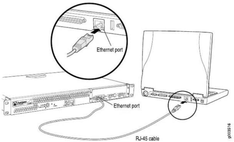
Figure 51: Connecting to the Fast Ethernet Port on the J4300 or J6300 Services Router

Connecting to the CLI Locally
If you plan to use the CLI to configure the router, you must connect through the console port, as shown in Figure 52 and Figure 53.

NOTE: Figure 52 and Figure 53 show a connection to a local management device. A remote connection to the router through a modem requires the cable and connector shown (provided in the router's accessory box), plus a DB-9 female to DB-25 male (or similar) adapter for your modem, which you must purchase separately.
To connect to the CLI using a local management device through the console port on the router:
- Turn off power to the router.
- Turn off the power to the management device, such as a PC or laptop computer, that you are using to access the CLI.
- Plug one end of the Ethernet cable supplied with your router into the RJ-45 to DB-9 serial port adapter supplied with your router (see Figure 52 and Figure 53).
- Plug the RJ-45 to DB-9 serial port adapter into the serial port on the management device (see Figure 52 and Figure 53).
- Connect the other end of the Ethernet cable to the console port on the router (Figure 52 and Figure 53).
- Turn on the power to the management device.
-
Start your asynchronous terminal emulation application (such as Microsoft Windows Hyperterminal) and select the appropriate COM port to use (for example, COM1).
-
Configure the port settings as follows:
- Power on the router by pressing the power button on the front panel. Verify that the POWER LED on the front panel turns green.
The terminal emulation screen on your management device displays the boot sequence. When the router has finished booting, a login prompt appears.
- Log in as the user "root". No password is required at initial connection, but you must assign a root password before committing any configuration settings.
Figure 52: Connecting to the Console Port on the J2300 Services Router

Figure 53: Connecting to the Console Port on the J4300 or J6300 Services Router

Connecting to the CLI Remotely
You can connect to the CLI from a remote location through two dial-up modems: a modem that is connected to the console port on the Services Router and a second modem connected to a remote management device. The modem connection allows you to remotely perform the same console operations you can perform locally.
This section contains the following topics:
■Configuring the Modem at the Router End on page 116
■Connecting the Modem to the Console Port on page 117
■Connecting to the CLI at the User End on page 117
Configuring the Modem at the Router End

NOTE: These instructions use Hayes-compatible modem commands to configure the modem. If your modem is not Hayes-compatible, refer to the documentation for your modem and enter equivalent modem commands.
Before you can connect a dial-up modem to the console port on the Services Router, you must configure the modem to accept a call on the first ring and accept Data Terminal Ready (DTR) signals. You must also disable flow control on the modem.
To configure the modem on the router end:
- Connect the modem to a PC or laptop computer.
- Power on the modem.
- From the PC or laptop computer, start your asynchronous terminal emulation application (such as Microsoft Windows Hyperterminal) and select the COM port to which the modem is connected (for example, COM1).
- Configure the port settings as follows:
■Bits per second: 9600
■Data bits: 8
■Parity: None
■Stop bits: 1
■Flow control: None
- In the HyperTerminal window, enter AT.
An OK response verifies that the modem communicates successfully with the COM port on the PC or laptop.
- To configure the modem to answer a call on the first ring, enter ATSO=1.
- To configure the modem to accept modem control Data Terminal Ready (DTR) signals, enter AT&D1.
- To disable flow control, enter AT&KO.
- To save modem settings, enter AT&W.
Connecting the Modem to the Console Port

NOTE: Most modems have an RS-232 DB-25 connector. You must separately purchase an adapter to connect your modem to the RJ-45 to DB-9 adapter and Ethernet cable supplied with the router.
To connect the dial-up modem to the console port on the router:
- Turn off power to the router.
- Turn off the power to the modem.
- Plug one end of the Ethernet cable supplied with your router into the console port on the router.
- Plug the other end of the Ethernet cable into the RJ-45 to DB-9 serial port adapter supplied with your router.
- Connect the serial port adapter to a separately purchased DB-9 female to DB-25 male adapter, or other adapter appropriate for your modem.
- Plug the modem adapter into the DB-25 connector on the modem.
- Connect the modem to your telephone network.
- Turn on the power to the modem.
- Power on the router by pressing the power button on the front panel. Verify that the POWER LED on the front panel turns green.
Connecting to the CLI at the User End
To remotely connect to the CLI through a dial-up modem connected to the console port on the router:
-
At your remote location, connect a modem to a management device such as a PC or laptop computer.
-
On the PC or laptop computer, start your asynchronous terminal emulation application (such as Microsoft Windows Hyperterminal).
-
Select the COM port to which the modem is connected (for example, COM1).
-
Configure the port settings as follows:
- In the HyperTerminal window, enter AT.
An OK response verifies that the modem communicates successfully with the COM port on the PC or laptop.
- To dial the modem that is connected to the console port on the router, enter ATDT remote-modem-number. For example, if the number of the modem connected to the console port on the router is 0013033033030, enter ATDT 0013033033030.
The router login prompt appears.
- Log in as the user "root". No password is required at initial connection, but you must assign a root password before committing any configuration settings.
Configuring Basic Settings with J-Web Quick Configuration
J-Web Quick Configuration allows you to configure basic settings. Figure 36 shows the Quick Configuration page for basic setup.
Before you configure the router, gather the information described in "Before You Begin" on page 110.
To configure basic settings with J-Web Quick Configuration:
- If you have not already done so, connect a management device to the fe-0/0/0 interface on port 0. For instructions, see "Connecting to the J-Web Interface" on page 111.
- If the Set Up Quick Configuration page is not displayed, select Configuration >Quick Configuration >Set Up.
- Enter information into the Set Up Quick Configuration page, as described in Table 47 on page 119.
- Click one of the following buttons:
■To apply the configuration and stay in the Set Up Quick Configuration page, click Apply.
■To apply the configuration and return to the Quick Configuration page, click OK.
■To cancel your entries and return to the Quick Configuration page, click Cancel.

NOTE: After initial configuration is complete, the Services Router stops functioning as a DHCP server. If you change the IP address of fe-0/0/0 and have the management device configured to use DHCP, you lose your DHCP lease and your connection to the router through the J-Web interface. To reestablish a connection, either set the IP address on the management device manually, or connect fe-0/0/0 to the management network and access the router another way—for example, through the console port.
- To check the configuration, see Displaying Basic Connectivity Configurations on page 124.
Table 47: Set Up Quick Configuration Summary
| Your ActionFunctionField | ||
| Identification | ||
| Type the hostname.Defines the hostname of the router.Host Name (require | ||
| Domain Name | machine belongs to. | Type the domain name.Defines the network or subnetwork that the |
| Root Password(required) | Sets the root password that user “root” can use to log in to the router. | Type a plain-text password that the system encrypts. NOTE: After a root password has been defined, it is required when you log in to the J-Web user interface or the CLI. |
| Verify Root Password(required) | correctly. | Retype the password.Verifies the root password has been typed |
| Time | ||
| Time Zone | located in. | From the list, select the appropriate time zone.Identifies the time zone tha |
| NTP Servers | Specify an NTP server that the router can reach to synchronize the system time. | To add an IP address, type it in the box to the left of the Add button, then click Add. To delete an IP address, click on it in the box above the Add button, then click Delete. |
| Current System Time | Synchronizes the system time with the NTP server, or manually set the system time and date. | ■ To immediately set the time using the NTP server, click Set Time via NTP. The router sends a request to the NTP server and synchronizes the system time. NOTE: If you are configuring other settings on this page, the router also synchronizes the system time using the NTP server when you click Apply or OK. ■ To set the time manually, click Set Time Manually. A pop-up window allows you to select the current date and time from lists. |
| Network | ||
| DNS Name Servers | Specify a DNS server that the router can use to resolve hostnames into addresses. | To add an IP address, type it in the box to the left of the Add button, then click Add.To delete an IP address, click on it in the box above the Add button, then click Delete. |
| Domain Search | Adds each domain name that the router is included in to the configuration so that they are included in a DNS search. | To add a domain name, type it in the box to the left of the Add button, then click Add.To delete a domain name, click on it in the box above the Add button, then click Delete. |
| Default Gateway | direct packets addressed to networks not explicitly listed in the routing table. | Type a 32-bit IP address, in dotted decimal notation.Defines a default gate |
| Loopback Address | Defines a reserved IP address that is always available on the router. If no address is entered, this address is set to 127.0.0.1/32. | Type a 32-bit IP address and prefix length, in dotted decimal notation. |
| fe-0/0/0 Address | Defines the IP address and prefix length of fe-0/0/0. The interface fe-0/0/0 is typically used as the management interface for accessing the router. The DHCP client sets this address to 192.168.1.1/24 if no DHCP server is found. | Type a 32-bit IP address and prefix length, in dotted decimal notation.NOTE: You must enter the fe-0/0/0 address on the Quick Configuration Set Up page before you click Apply or OK. If you do not manually configure this address, you will lose your connection to the J-Web interface when you click Apply or OK. |
| Management Access | ||
| Allow Telnet Access | Telnet. | To enable Telnet access, select the check box.Allows remote access to the |
| Allow JUNOScript over Clear-Text Access | Allows JUNOScript to access the router using a protocol for sending unencrypted text over a TCP connection. | To enable JUNOScript access over clear text, select the check box. |
| Allow SSH Access | Allows remote access to the router using SSH. | To enable SSH access, select the check box. |
Configuring Basic Settings with a Configuration Editor
To establish basic connectivity on a Services Router, you identify the router, connect the router to the network, and specify basic network settings.
In a typical network, the Services Router has the basic settings listed in Table 48 on page 121. Determine the values to set on the Services Router in your network.
Table 48: Sample Settings on a Services Router
| Sample ValueServices Router Property | |
| Services Router hostname | routera |
| SSH RSA public keyAccess for user “root” | |
| IP address of the NTP server used to synchronize system time on the Services Router | 10.148.2.21 |
| Services Router location | Sunnyvale, California, USA, which is in the America/Los_Angeles time zone |
| IP address of the DNS server to which DNS requests are sent | 10.148.2.32 |
| Domains to which the Services Router belongs | lab.router.net and router.net |
| IP address of a backup router to use while the Services Router is booting or if the routing protocol processes fail to start | 192.168.2.12/24 |
| Loopback IP address and prefix length for the Services Router lo0 interface | 172.16.1.24/32 |
| IP address and prefix length for the Services Router fe-0/0/0 interface | 192.168.1.1/24 |
You can configure basic settings in the J-Web interface from a device attached to the fe-0/0/0 interface on port 0. For instructions, see "Connecting to the J-Web Interface" on page 111. You can also connect to the CLI to configure basic settings. For instructions, see "Connecting to the CLI Locally" on page 113 and "Connecting to the CLI Remotely" on page 115.
To use a configuration editor to configure basic settings:
- Navigate to the top of the configuration hierarchy in either the J-Web or CLI configuration editor.
-
To configure basic settings, perform the configuration tasks described in Table 49 on page 122.
-
If you are using the J-Web interface, click Commit to view a summary of your changes, then click OK to commit the configuration. If you are using the CLI, commit the configuration by entering the commit command.
- To check the configuration, see Displaying Basic Connectivity Configurations on page 124.
Table 49: Configuring Basic Settings
| CLI Configuration EditorJ-Web Configuration EditorTas | ||
| Navigate to the System level in the configuration hierarchy. | 1. In the J-Web interface, selectConfiguration > View and Edit > Edit Configuration.2. Next to System, clickConfigure or Edit. | From the [edit] hierarchy level, enteredit system |
| Define the hostname of the router. | In the Host name box, type the hostname of the router—for example, routera. | Set the hostname. For example:set host-name routera |
| Name the domain in which the router is located. | In the Domain name box, type the domain name of the router—for example, lab.router.net. | Set the domain name. For example:set domain-name lab.router.net |
| Allow SSH remote access. | 1. In the Nested configuration section, next to Services, clickConfigure or Edit.2. Next to Ssh, clickConfigure or Edit.3. Click OK.4. Click OK a second time to return to the System level in the configuration editor hierarchy. | Set remote access for SSH:set services ssh |
| Define root authentication for access to the router.NOTE: For readability, the entire key is not shown. | 1. In the Nested configuration section, next to Root authentication, clickConfigure or Edit.2. Next to Ssh rsa, clickAdd New Entry.3. In the Authorized key box, type the RSA password—for example, ssh-rsa AAAAB3Nza...D9Y2gXF9ac==root@routera.lab.router.net4. Click OK.5. Click OK a second time to return to the System level in the configuration editor hierarchy. | Set the root password. For example:set root-authentication ssh-rsa“ssh-rsa AAAAB3Nza...D9Y2gXF9ac==root@routera.lab.router.net” |
| Define the time zone the router is located in. | In the Time zone list, select the time zone for your router—for example,America/Los_Angeles. | Set the time zone. For example:set time-zone America/Los_Angeles |
| Define the NTP server that NTP requests can be sent to. | 1. In the Nested configuration section, next to Ntp, click Configure or Edit. | Set the address of the NTP server. For example: |
| 2. Next to Server, click Add New Entry. | set ntp server 10.148.2.21 | |
| 3. In the Address box, type the NTP server's IP address—for example, 10.148.2.21 | ||
| 4. Click OK. | ||
| 5. Click OK a second time to return to the System level in the configuration editor hierarchy. | ||
| Define the DNS server that receives DNS requests. | 1. Next to Name server, click Add New Entry. | Set the address of the DNS server. For example: |
| 2. In the Address box, type the address of the DNS server—for example, 10.148.2.32. | set name-server 10.148.2.32 | |
| 3. Click OK. | ||
| Add each domain that the router belongs to. | 1. Next to Domain search, click Add New Entry. | Set the domains to be searched. For example: |
| 2. In the Value box, type the name of the domain in which the router is located—for example, lab.router.net. | set domain-search lab.router.net | |
| 3. Click OK. | set domain-search router.net | |
| 4. Next to Domain search, click Add New Entry. | ||
| 5. In the Value box, type the name of another domain that the router belongs to—for example, router.net. | ||
| 6. Click OK. | ||
| Define the backup router to be used when the router is booting or the routing protocol processes are not running. | In the Backup router section, next to Address, type the IP address of the backup router—for example, 192.168.2.44. | Set the address for the backup router. For example: |
| set backup router address 192.168.2.44 | ||
| Define the IP address for lo0.0. | 1. In the configuration editor hierarchy, next to Interfaces, click Configure or Edit. | 1. From the [edit] hierarchy level, enter edit interfaces |
| 2. In the Interface table, locate the lo0 row and click Unit. | ||
| 3. In the Unit table, click 0, and in the Family section next to Inet, click Configure or Edit. | 2. Delete the existing IP address: delete lo0 unit 0 family inet address | |
| 4. To delete the existing IP address, click the Discard button. Select the Delete Configuration Below This Point option button from the next display. | 3. Set the IP address and prefix length of lo0.0. For example: set lo0 unit 0 family inet address 172.16.1.24/32 | |
| 5. Next to Address, click Add new entry. | ||
| 6. In the Source box, type the address and prefix length for the loopback interface—for example, 172.16.1.24/32. | ||
| 7. Click OK. | ||
| Define the IP address for fe-0/0/0. | 1. In the configuration editor hierarchy, next to Interfaces, click Configure or Edit. | 1. Delete the existing IP address: delete fe-0/0/0 unit 0 family inet address. |
| 2. In the Interface table, locate the fe-0/0/0 row and click Unit. | ||
| 3. In the Unit table, click 0, and in the Family section next to Inet, click Configure or Edit. | 2. Set the IP address and prefix length of fe-0/0/0. For example: set fe-0/0/0 unit 0 family inet address 192.168.1.1/24 | |
| 4. To delete the existing IP address, click the Discard button. Select the Delete Configuration Below This Point option button from the next display. | ||
| 5. Next to Address, click Add new entry. | ||
| 6. In the Source box, type the address and prefix length for the management interface—for example, 192.168.1.1/24. | ||
| 7. Click OK. | ||
Verifying Basic Connectivity
To verify that the Services Router has the settings you configured, perform the following task.
Displaying Basic Connectivity Configurations
Purpose Verify the configuration of basic connectivity. Because the basic connectivity settings appear in different places in the configuration hierarchy, displaying the entire configuration at once makes viewing the settings easier.
Action From the J-Web interface, select
Configuration > View and Edit > View Configuration Text. Alternatively, from configuration mode in the CLI, enter the show command. The following sample output displays the sample values configured in Table 49 on page 122. Your output displays the values you set.
system {
    host-name routera;
    domain-name lab.router.net;
    domain-search [ lab.router.net router.net ];
    backup-router 192.168.2.44;
    time-zone America/Los_Angeles;
    root-authentication {
    ssh-rsa "ssh-rsa AAAAB3Nza...D9Y2gXF9ac==root@routera.lab.router.net";
    }
    name-server {
    10.148.2.32;
    }
    services {
    }
    ntp {
    server 10.148.2.21;
    }
}
interfaces {
    fe-0/0/0 {
    unit 0 {
    family inet {
    address 192.168.1.1/24;
    }
    }
    }
    lo0 {
    unit 0 {
    family inet {
    address 172.16.1.24/32;
    }
    }
    }
}
What It Means The output shows the configuration of basic connectivity. Verify that the values displayed are correct for your Services Router. For more information about the format of a configuration file, see the J-series Services Router Basic LAN and WAN Access Configuration Guide.
J2300, J4300, and J6300 Services Router Getting Started Guide
Chapter 8
Configuring Secure Web Access
You can manage a Services Router remotely through the J-Web interface. To communicate with the Services Router, the J-Web interface uses Hypertext Transfer Protocol (HTTP). HTTP allows easy Web access but no encryption. The data that is transmitted between the Web browser and the router by means of HTTP is vulnerable to interception and attack. To enable secure Web access, a Services Router supports Hypertext Transfer Protocol over Secure Sockets Layer (HTTPS). You can enable HTTP or HTTPS access on specific interfaces and ports as needed.
You can use J-Web Quick Configuration, the J-Web configuration editor, or the CLI configuration editor to configure secure Web access.
This chapter contains the following topics. For more information about the J-Web interface, see the J-Web Interface User Guide.
■Secure Web Access Terms on page 127
■Secure Web Access Overview on page 128
■Before You Begin on page 128
■ Configuring Secure Web Access with Quick Configuration on page 129
■ Configuring Secure Web Access with a Configuration Editor on page 132
■Verifying Secure Web Access on page 133
Secure Web Access Terms
Before configuring secure Web access, become familiar with the terms defined in Table 50 on page 127.
Table 50: Secure Web Access Terms
| DefinitionTerm | |
| certificate authority (CA) | Third-party organization or company that issues digital certificates used to create digital signatures and public-private key pairs. The CA guarantees the identity of the individual or device that presents the digital certificate. |
| Hypertext Transfer Protocol (HTTP) | Protocol used to publish and receive information on the Web, such as text and graphics files. |
| Hypertext Transfer Protocol over Secure Sockets Layer (HTTPS) | Protocol similar to HTTP with an added encryption layer that encrypts and decrypts user page requests and pages that are returned by a Web server. HTTPS is used for secure communication, such as payment transactions. |
| Privacy-Enhanced Mail (PEM) | Technique for securely exchanging electronic mail over a public medium. PEM is based upon public key infrastructure (PKI) standards like X.509 certificates. SSL certificates are partly based on PEM and end in the suffix .pem. |
| RSA | Public key cipher that can be used for encrypting messages and making digital signatures. RSA uses a well-known encryption and authentication algorithm that is a part of popular Web browsers. |
| Secure Sockets Layer (SSL) | Protocol that encrypts security information before transmitting data across a network. SSL requires two keys to encrypt data—a public key known to everyone and a private or secret key known only to the recipient of the message—and an authentication certificate. Most popular Web browsers support SSL. |
| SSL certificate | Secure electronic identifier conforming to the X.509 standard, definitively identifying an individual, system, company, or organization. In addition to identification data, the digital certificate contains a serial number, a copy of the certificate holder's public key, the identity and digital signature of the issuing certificate authority (CA), and an expiration date. |
Secure Web Access Overview
A Services Router uses the Secure Sockets Layer (SSL) protocol to provide secure management of Services Routers through the Web interface. SSL uses public-private key technology that requires a paired private key and an authentication certificate for providing the SSL service. SSL encrypts communication between your router and the Web browser with a session key negotiated by the SSL server certificate.
An SSL certificate includes identifying information such as a public key and a signature made by a certificate authority (CA). When you access the router through HTTPS, an SSL handshake authenticates the server and the client and begins a secure session. If the information does not match or the certificate has expired, you are not able to access the router through HTTPS.
Without SSL encryption, communication between your router and the browser is sent in the open and can be intercepted. We recommend that you enable HTTPS access on your WAN interfaces.
On J-series Services Routers, HTTP access is enabled by default on the built-in management interfaces. By default, HTTPS access is supported on any interface with an SSL server certificate.
Before You Begin
Before you begin initial configuration, complete the following tasks:
■ Establish basic connectivity. See “Establishing Basic Connectivity” on page 105.
- Obtain an SSL certificate from a trusted signing authority. See “Generating SSL Certificates” on page 129.
Generating SSL Certificates
To enable secure Web access, you must first generate a digital SSL certificate, and then enable HTTPS access on the Services Router.
To generate an SSL certificate:
- Enter the following openssl command in your Secure Shell command-line interface. The openssl command generates a self-signed SSL certificate in the privacy-enhanced mail (PEM) format. It writes the certificate and an unencrypted 1024-bit RSA private key to the specified file.
% openssl req -x509 -nodes -newkey rsa:1024 -keyout filename.pem -out filename.pem
Replace filename with the name of a file in which you want the SSL certificate to be written—for example, new.pem.
- When prompted, type the appropriate information in the identification form. For example, type US for the country name.
- Display the contents of the file new.pem.
cat new.pem
Copy the contents of this file for installing the SSL certificate.
Use can use either J-Web Quick Configuration or a configuration editor to install the SSL certificate and enable HTTPS.
Configuring Secure Web Access with Quick Configuration
Use the Secure Access Quick Configuration page to enable HTTP and HTTPS access on interfaces for managing Services Routers through the Web interface. You can also install SSL certificates and enable JUNOScript over SSL with the Secure Access page.
Figure 54 shows the Secure Access Quick Configuration page.
Figure 54: Quick Configuration Secure Access Page
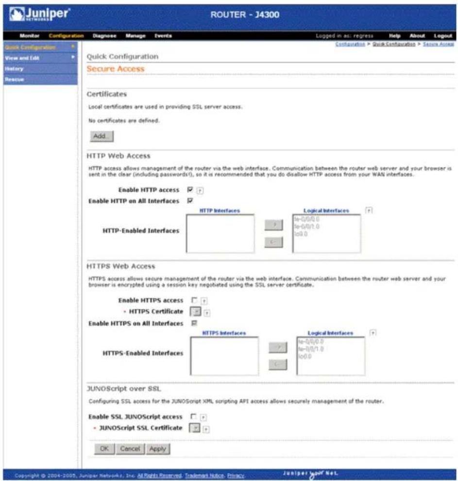
To configure Web access settings in the J-Web interface:
- Generate an SSL certificate. An SSL certificate is required for enabling HTTPS or SSL JUNOScript access. Skip this step if you are enabling HTTP access. For instructions about generating SSL certificates, see "Generating SSL Certificates" on page 129.
- In the J-Web user interface, select Configuration > Quick Configuration > Secure Access.
- Enter information into the Secure Access Quick Configuration page, as described in Table 51 on page 131.
- Click one of the following buttons:
■To apply the configuration and stay on the Quick Configuration page, click Apply.
■To apply the configuration and return to the Quick Configuration page, click OK.
■To cancel your entries and return to the Quick Configuration page, click Cancel.
- To verify that Web access is enabled correctly, connect to the Services Router using one of the following methods:
■ For HTTP access—In your Web browser, type http://URL or http://IP address.
■ For HTTPS access—In your Web browser, type https://URL or https://IP address.
■ For SSL JUNOScript access—A JUNOScript client such as JUNOScope is required. For information about how to log in to JUNOScope, see the JUNOScope Software User Guide.
- To verify the secure Web access configuration, see "Verifying Secure Web Access" on page 133.
Table 51: Secure Access Quick Configuration Summary
| Your ActionFunctionField | ||
| Certificates | ||
| Certificates | Displays digital certificates required for SSL access to the Services Router. | To add a certificate:1. Click Add. Opens the Add a Local Certificate page. |
| Allows you to add and delete SSL certificates. | 2. Type a name in the Certificate Name box—for example, new. | |
| For information about how to generate an SSL certificate, see “Generating SSL Certificates” on page 129. | 3. Paste the generated certificate and RSA private key in the Certificate box. | |
| To delete a certificate, select it and click Delete. | ||
Enable HTTP Access
| Enables HTTP access on interfaces. Enable HTTP enables HTTP access, select the Enable HTTP access check box. | ||
| Enable HTTP on All Interfaces | Enables HTTP access on all interfaces at one time. | To enable HTTP access on all interfaces, select the Enable HTTP on All Interfaces check box. |
| Your ActionFunctionField | ||
| HTTP-Enabled Interfaces | Specifies interfaces on which you want to enable HTTP access. | Select and deselect interfaces by clicking the direction arrows:■ To enable HTTP access on an interface, add the interface to the HTTP Interfaces list.■ To disable HTTP access on an interface, add the interface to the Logical Interfaces list. |
| HTTPS Web Access | ||
| Enables HTTPS access on interfaces. Enable HTTPS access, select the Enable HTTPS access check box. | ||
| HTTPS Certificate | Specifies SSL certificates to be used for encryption.This field is available only after you have created an SSL certificate. | To specify the HTTPS certificate, select a certificate from the HTTPS Certificate list—for example,new. |
| Enable HTTPS on All Interfaces | Enables HTTPS on all interfaces at one time. | To enable HTTPS on all interfaces, select the Enable HTTPS on All Interfaces check box. |
| HTTPS-Enabled Interfaces | Allows you to specify interfaces on which you want to enable HTTPS access. | Select and deselect interfaces by clicking the direction arrows:■ To enable HTTPS access on an interface, add the interface to the HTTPS Interfaces list.■ To disable HTTPS access on an interface, add the interface to the Logical Interfaces list. |
| JUNOScript over SSL | ||
| Enable SSL JUNOScript access | Enables secured SSL access to the JUNOScript XML scripting API. | To enable SSL access, select the Enable SSL JUNOScript access check box. |
| JUNOScript SSL Certificate | Specifies SSL certificates to be used for encryption.This field is available only after you create at least one SSL certificate. | To enable an SSL certificate, select a certificate from the JUNOScript SSL Certificate list—for example,new. |
Configuring Secure Web Access with a Configuration Editor
You can manage your Services Router using a secure Web connection by enabling HTTPS.
To enable HTTPS on your Services Router:
- Navigate to the top of the configuration hierarchy in either the J-Web or CLI configuration editor.
-
Perform the configuration tasks described in Table 52 on page 133.
-
If you are finished configuring the router, commit the configuration.
- To check the configuration, see "Verifying Secure Web Access" on page 133.
Table 52: Configuring a Secure Web Access
| CLI Configuration EditorJ-Web Configuration EditorTask | ||
| Navigate to the Security level in the configuration hierarchy. | 1. In the J-Web interface, selectConfiguration > EditConfiguration > View and Edit. | From the [edit] hierarchy level, enteredit security |
| 2. Next to Security, click Configure or Edit. | ||
| Import the SSL certificate that you have generated—for example, new.For information about generating SSL certificates, see “Generating SSL Certificates” on page 129. | 1. Next to Certificates, click Configure. | Enter |
| 2. Next to Local, click Add new entry. | set certificates local new load-key-filepath | |
| 3. In the Name box, type a name for the certificate to be imported—for example, new. | Replace path with a path or URL to the file containing an SSL certificate and private key in PEM format—for example,/var/tmp/new.pem | |
| 4. In the Certificate box, paste the generated SSL certificate and private key. | ||
| 5. Click OK. | ||
| Enable HTTPS access and specify the SSL certificate to be used for authentication. | 1. On the main Configuration page next to System, click Configure or Edit. | From the [edit system] hierarchy level, enter set services web-management httpslocal-certificate new port 8443 |
| 2. Select the Services check box and click Edit next to it. | ||
| Specify the port on which HTTPS access is to be enabled—for example, TCP port 8443. | 3. Next to Web management, click Edit. | |
| 4. Select the Https check box and click Edit next to it. | ||
| NOTE: You can enable HTTPS access on specified interfaces also. If you enable HTTPS without specifying an interface, HTTPS is enabled on all interfaces. | 5. In the Local certificate box, type the name of the certificate—for example, new. | |
| 6. In the Port box, type 8443. | ||
| 7. Click OK. | ||
Verifying Secure Web Access
To verify that the Services Router has the secure access settings you configured, perform the following tasks:
■Displaying an SSL Certificate Configuration
■Displaying a Secure Access Configuration
Displaying an SSL Certificate Configuration
Purpose Display the SSL certificate configuration.
Action From the J-Web interface, select
Configuration > View and Edit > View Configuration Text. Alternatively, from configuration mode in the CLI, enter the show security command.
The following sample output displays an SSL certificate generated with instructions in "Generating SSL Certificates" on page 129.
[edit]
user@RO# show security
certificates {
    local {
    new {
    "—BEGIN RSA PRIVATE KEY—\nMIICXQIBAAKBgQC/C5UI4frNqbi
    qPwbTiOkJvqoDw2YgYse0Z5zzVJyErgSg954T\nEuHM67Ck8hAOrCnbOYO+SY
    Y5rCXLf4+2s8k9EypLtYRw/Ts66DZoXI4viqE7HSsK\n5sQw/UDBIw7/MJ+OpA
    ... KYiFf4CbBBbjIMQJOHFudW6ISVBsIONkzX+FT\ni95ddka6iIRnArEb4VFCRh+
    e1QBdp1UjziYf7NuzDx4Z\n —END RSA PRIVATE KEY—\n—BEGIN
    CERTIFICATE— \nMIIDjDCCAvWgAwIBAgIBADANBgkqhkiG9wOBAQQ ...
    FADCBkTELMAkGA1UEBhMCdXMx\nCzAJBgNVBAgTAmNhMRlwEAYDVQQHEwlzdW5ue
    HB1YnMxDTALBgNVBAMTBGpucHlxJDAiBgkqhkiG\n9w0BCQEWFW5iaGFyZ2F2YUB
    fLUYAnBYmsYWOH\n —END CERTIFICATE—\n"; ## SECRET-DATA
    }
    }
}
What It Means The output shows the intended secure access configuration. For more information about the format of a configuration file, see the J-series Services Router Basic LAN and WAN Access Configuration Guide.
Displaying a Secure Access Configuration
Purpose Verify the secure access configuration.
Action From the J-Web interface, select
Configuration > View and Edit > View Configuration Text. Alternatively, from configuration mode in the CLI, enter the show system services command.
The following sample output displays the sample values for secure Web access as configured in Table 52 on page 133.
[edit]
user@RO# show system services
web-management {
http;
https {
port 8443;
local-certificate new;
}
}
What It Means
The output shows the intended secure access configuration. For more information about the format of a configuration file, see the J-series Services Router Basic LAN and WAN Access Configuration Guide.
J2300, J4300, and J6300 Services Router Getting Started Guide
Chapter 9
Configuring Autoinstallation
If you are setting up many J-series Services Routers, autoinstallation can help automate the configuration process. You can use either the J-Web configuration editor or CLI configuration editor to configure autoinstallation. The J-Web interface does not include Quick Configuration pages for autoinstallation.
This chapter contains the following topics:
■Autoinstallation Terms on page 137
■Autoinstallation Overview on page 137
■Before You Begin on page 139
■ Configuring Autoinstallation with a Configuration Editor on page 140
■Verifying Autoinstallation on page 141
Autoinstallation Terms
Before configuring autoinstallation, become familiar with the terms defined in Table 53 on page 137.
Table 53: Autoinstallation Terms
| DefinitionTerm | |
| autoinstallation | Automatic configuration of a Services Router when it is powered on without a valid configuration file or is configured specifically for autoinstallation. Autoinstallation is useful when deploying multiple Services Routers. |
| default configuration | Configuration state when a boot file cannot be located during autoinstallation. |
| host-specific configuration | Configuration state when a specific filename is used during TFTP server requests. |
Autoinstallation Overview
Autoinstallation provides automatic configuration when a new Services Router is powered on without a configuration file or for a Services Router configured for
autoinstallation. The autoinstallation process begins anytime a Services Router is powered on and a valid configuration file is not found in the nonvolatile RAM (NVRAM). Typically, a configuration file is unavailable when a Services Router is powered on for the first time, or if the configuration file is deleted from the NVRAM. The autoinstallation features is useful deploying multiple Services Router in networks.
This overview contains the following topics:
■Autoinstallation Interfaces on page 138
■Autoinstallation Process on Services Router on page 138
■Automatic Configuration of a New Services Router on page 139
Autoinstallation Interfaces
Autoinstallation can take place through either a management interface or a serial interface on the Services Router. If a LAN interface with High-level Data Link Control (HDLC) encapsulation is found on the Services Router, autoinstallation attempts to obtain an IP address using DHCP requests, bootstrap protocol (BOOTP), or Reverse Address Resolution Protocol (RARP) requests.
If a serial interface with Frame Relay encapsulation is connected, then the Services Router attempts to obtain an IP address using BOOTP requests. On a serial interface without Frame Relay encapsulation, the Services Router uses Serial Line Address Request Protocol (SLARP).
Autoinstallation Process on Services Router
When the Services Router is powered on for the first time, autoinstallation attempts the following on each connected interface simultaneously:
- The Services Router sends out DHCP, BOOTP, RARP, or SLARP requests to obtain an IP address.
- If a DHCP server responds, the router obtains the following:
■An IP address and subnet mask
■The address of the Trivial File Transfer Protocol (TFTP), Hypertext Transfer Protocol (HTTP), or File Transfer Protocol (FTP) server with the configuration file
■The IP address of the TFTP server
Optionally, the hostname of the TFTP server is obtained from the DHCP server. Usually, the TFTP address or name is specified, not both. If the name is specified, a DNS server must be available to translate the name of the TFTP server into an IP address.
If the TFTP server is not on the same LAN segment as the new Services Router, or if a specific router is required by the network, then the IP address of an intermediary router must be specified. This address is used as the location to receive TFTP requests for autoinstallation.
Automatic Configuration of a New Services Router
After a new Services Router obtains an IP address, autoinstallation attempts to download a configuration file using one of the following methods:
■Host-specific configuration. If the DHCP server specifies the name of the host-specific configuration file (boot file), the specific filename is used in the TFTP server request. The new Services Router makes three unicast TFTP requests for the specified boot file. If these attempts fail, then the router makes three broadcast requests to any available TFTP server looking for the specified boot file.
■Default configuration. If the boot file cannot be located, or the new Services Router does not receive a specified boot filename from the DHCP server, the autoinstallation process then unicasts or broadcasts TFTP requests for a default router configuration file called network.conf. The default configuration file, network.conf, contains hostname-to-IP address mapping information.
If there is no entry for the new Services Router, the autoinstallation process sends out a DNS request and attempts to resolve the hostname. If the J-series Services Router can determine its hostname, a TFTP request is sent for the hostname.conf file. The variable, hostname, is replaced by the hostname of the router. If the new Services Router is unable to map its IP address to a hostname, then TFTP requests are sent for the default configuration file, router.conf.
After the configuration file is downloaded from the TFTP server, it is loaded onto the Services Router and committed.
Before You Begin
To configure a network for autoinstallation of Services Routers, complete the following tasks:
■Configure a DHCP server on your network to meet your network requirements.
■Create a configuration file and place it on a TFTP server on the network. A configuration file can be either of the following:
A host-specific file with the name hostname.conf where hostname is the name of the Services Router.
A default configuration file with the minimum configuration necessary to Telnet into the new Services Router for further configuration.
■Physically attach the Services Router to the network using one or more of the following interface types:
Ethernet
■ Serial with HDLC encapsulation
■If the DHCP response contains only the hostname for the TFTP server, add IP address-to-hostname mapping for the TFTP server to a DNS database file.
■To use an existing router to receive TFTP requests and forward them to the TFTP server, add additional IP addresses of the hosts providing the TFTP service.
If you choose to create a host-specific configuration file, you must also complete the following tasks:
■Configure the DHCP server to provide a configuration filename to the new Services Router. This filename is then used to request a configuration file from a TFTP server. Copy the host-specific configuration to the TFTP server.
■ Copy a default configuration file named network.conf to the TFTP server. This file contains IP address-to-hostname mappings in the format ip host ip address hostname entries. If a host-specific configuration file is not specified by the DHCP server, this file is used to create a hostname for the new Services Router.
■Add the IP address-to-hostname mapping for the new Services Router to a DNS database file.
Configuring Autoinstallation with a Configuration Editor
To configure autoinstallation:
- Navigate to the top of the configuration hierarchy in either the J-Web or CLI configuration editor.
- To configure autoinstallation, perform the configuration tasks described in Table 54 on page 140.
- If you are using the J-Web interface, click Commit to view a summary of your changes, then click OK to commit the configuration. If you are using the CLI, commit the configuration by entering the commit command.
- To check the configuration, see "Verifying Autoinstallation" on page 141.
Table 54: Configuring Autoinstallation
| CLI Configuration EditorJ-Web Configuration Editor | ||
| Navigate to the System level in the configuration hierarchy. | 1. In the J-Web interface, selectConfiguration > View and Edit > EditConfiguration. | From the [edit] hierarchy level, enteredit system |
| 2. Next to System, click Configure or Edit. | ||
| CLI Configuration EditorJ-Web Configuration Editor | ||
| Enable autoinstallation. | Select Autoinstallation, and then click Configure. | Enter set autoinstallation configuration servers url. |
| Add the configuration servers by specifying the URL address of a server from which to obtain configuration files. | 1. Next to Configuration servers, click Add new entry.2. Type the location of the configuration server in the Url box.3. If a password is required to access the server, type it into the Password box.4. Click OK to return to the Autoinstallation page. | |
| Configure one or more Ethernet or serial interfaces to perform autoinstallation, and one or two procurement protocols for each interface. The router uses the protocols to send a request for an IP address from the interface.■ BOOTP—Sends requests over all interfaces.■ RARP—Sends requests over Ethernet interfaces.■ SLARP—Sends requests over serial interfaces. | 1. Next to Interfaces, click Add new entry.2. Type the name of the interface into the Interface name box.3. Select one or two types of protocol used by autoinstallation over the interface. You can select Bootp, Rarp, or Slarp.4. Click OK to return to the Autoinstallation page. | Enter set autoinstallation interfaces interface-name, then one of the following protocols:■ bootp■ rarp■ slarpFor example, to set two address procurement protocols, enter a command like the following example:set autoinstallation interfaces fe-2/0/0 bootp rarp |
Verifying Autoinstallation
To verify that a Services Router is configured for autoinstallation, perform the following task.
Verifying Autoinstallation Status
Purpose Display the status of the autoinstallation feature on a Services Router.
Action From the CLI, enter the show system autoinstallation status command.
user@host> show system autoinstallation status
Autoinstallation status:
Master state: Active
Last committed file: None
Configuration server of last committed file: 10.25.100.1
Interface:
Name: fe-0/0/0
State: Configuration Acquisition
Acquired:
Address: 192.168.124.75
Hostname: host-fe-000
Hostname source: DNS
Configuration filename: router-fe-000.conf
Configuration filename server: 10.25.100.3
Address acquisition:
Protocol: DHCP Client
Acquired address: None
Protocol: RARP Client
Acquired address: None
Interface:
Name: fe-0/0/1
State: None
Address acquisition:
Protocol: DHCP Client
Acquired address: None
Protocol: RARP Client
Acquired address: None
What It Means
The output shows the parameters configured for autoinstallation. Verify that the values displayed are correct for the Services Router when it is deployed on the destination network.
Chapter 10
Installing and Managing J-series Licenses
To enable some JUNOS software features on a J-series Services Router, you must purchase, install, and manage separate software licenses. The presence on the router of the appropriate software license keys (passwords) determines the features you can configure and use.
For information about how to purchase J-series software licenses, contact your Juniper Networks sales representative.
This chapter contains the following topics:
■J-series License Overview on page 143
■Before You Begin on page 144
■Managing J-series Licenses with the J-Web Interface on page 145
■Managing J-series Licenses with the CLI on page 148
■Verifying J-series License Management on page 149
J-series License Overview
Each J-series feature license is valid for only a single Services Router. To manage the licenses, you must understand the components of a license key.
This section contains the following topics:
■Software Feature Licenses on page 144
■License Key Components on page 144
Software Feature Licenses
Each feature license is tied to exactly one software feature, and that license is valid for exactly one Services Router. Table 55 on page 144 lists the Services Router software features that require licenses.
Table 55: J-series Services Router Software Feature Licenses
| License NameLicensed Software Feature | |
| IBM Networking | |
| Data link switching (DLSw) on all J-series Services Routers | J-series Services Router Software License for Data Link Switching (DLSw) Support |
| Traffic Analysis | |
| J-Flow traffic analysis—all configuration statements within the [edit forwarding-options sampling] and [edit forwarding-options accounting] hierarchies. | J-series Services Router Software License for J-Flow Traffic Analysis |
| BGP Route Reflectors | |
| Advanced Border Gateway Protocol (BGP) features that enable route reflectors—all configuration statements within the [edit protocols bgp cluster] hierarchy. BGP clusters allow routers to act as route reflectors by enabling the readvertising of BGP routes to internal peers. | J-series Services Router Software License for Advanced Border Router Protocol Support |
License Key Components
A license key consists of two parts:
■ License ID—Alphanumeric string that uniquely identifies the license key. When a license is generated, it is given a license ID.
■ License data—Block of binary data that defines and stores all license key objects.
For example, in the following typical license key, the string li29183743 is the license ID, and the trailing block of data is the license data:
1i29183743 4ky27y acasck 82fsj6 jzsn4q ix8i8d adj7kr
8uq38t ix8i8d jzsn4q ix8i8d 4ky27y acasck
82fsj6 ii8i7e adj7kr 8uq38t ks2923 a9382e
The license data defines the device ID for which the license is valid and the version of the license.
Before You Begin
Before you begin managing the J-series licenses, complete the following tasks:
■Purchase the licenses you require.
■ Establish basic connectivity. See “Establishing Basic Connectivity” on page 105.
Managing J-series Licenses with the J-Web Interface
To manage licenses with the J-Web interface, you perform the following tasks:
■Adding New Licenses with the J-Web Interface on page 146
■Deleting Licenses with the J-Web Interface on page 147
■Displaying License Keys with the J-Web Interface on page 147
■Downloading Licenses with the J-Web Interface on page 147
Figure 55 shows the J-Web Licenses page.
Figure 55: Licenses Page
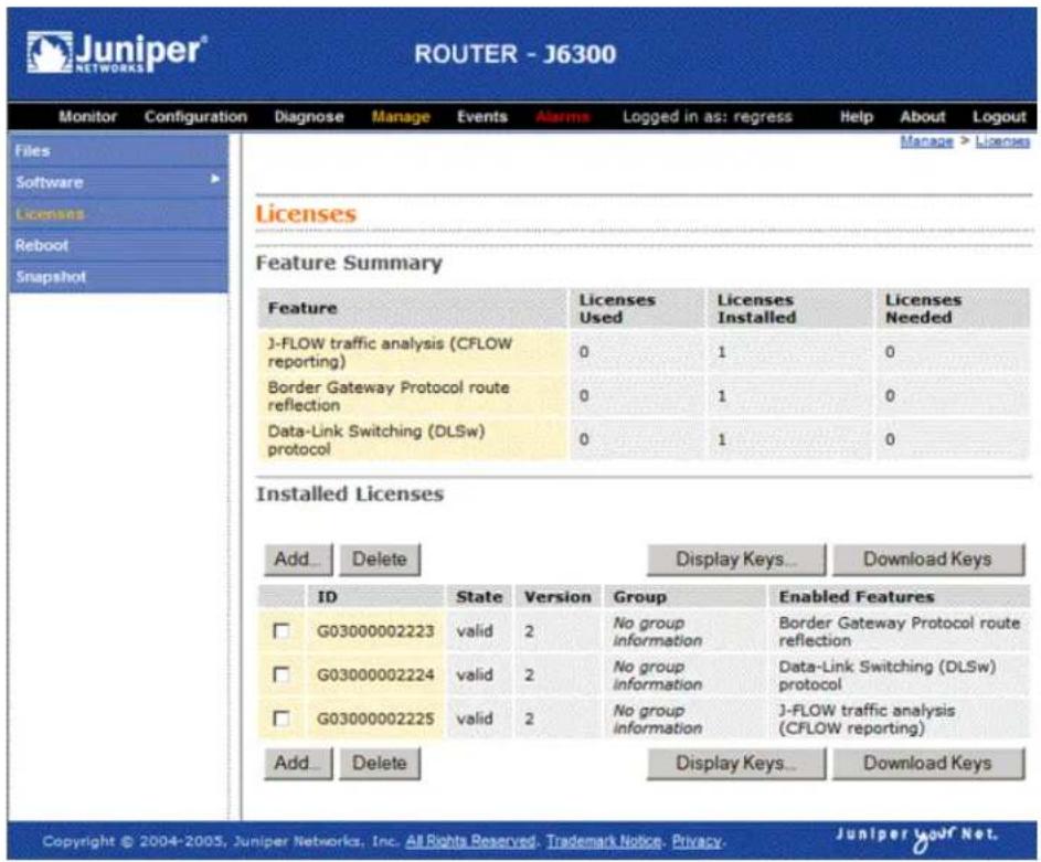
The Licenses page displays a summary of licensed features that are configured on the Services Router and a list of the licenses that are installed on the router. The information on the license management page is summarized in Table 56 on page 146.
Table 56: Summary of License Management Fields
| DefinitionField Name | |
| Feature Summary | |
| Feature | Name of the licensed feature:■ J-series licenses listed in Table 55 on page 144.■ All features—All-inclusive licenses |
| Licenses Used | Number of licenses currently being used on the router. Usage is determined by the configuration on the router. If a feature license exists and that feature is configured, the license is considered used. |
| Number of licenses installed on the router for the particular feature.Licenses Installed | |
| Licenses Needed | Number of licenses required for legal of use the feature. Usage is determined by the configuration on the router: If a feature is configured and the license for that feature is not installed, a single license is needed. |
| Installed Licenses | |
| Unique alphanumeric ID of the license.ID | |
| State | Valid—The installed license key is valid.Invalid—The installed license key is not valid. |
| Numeric version number of the license key.Version | |
| Group | If the license defines a group license, this field displays the group definition.If the license requires a group license, this field displays the required group definition.NOTE: Because group licenses are currently unsupported, this field is always blank. |
| Name of the feature that is enabled with the particular license.Enabled Features | |
Adding New Licenses with the J-Web Interface
To add a new license key on a Services Router with the J-Web license manager:
- In the J-Web interface, select Manage > Licenses.
- Under Installed Licenses, click Add to add a new license key.
- Do one of the following, using a blank line to separate multiple license keys:
In the License File URL box, type the full URL to the destination file containing the license key to be added.
In the License Key Text box, paste the license key text, in plain-text format, for the license to be added.
- Click OK to add the license key.
- Go on to "Verifying J-series License Management" on page 149.
Deleting Licenses with the J-Web Interface
To delete one or more license keys from a Services Router with the J-Web license manager:
- In the J-Web interface, select Manage > Licenses.
- Select the check box of the license or licenses you want to delete.
- Click Delete.
- Go on to "Verifying J-series License Management" on page 149.
Displaying License Keys with the J-Web Interface
To display the license keys installed on a Services Router with the J-Web license manager:
- In the J-Web interface, select Manage > Licenses.
- Under Installed Licenses, click Display Keys to display all the license keys installed on the router.
A screen displaying the license keys in text format appears. Multiple licenses are separated by a blank line. - Go on to "Verifying J-series License Management" on page 149.
Downloading Licenses with the J-Web Interface
To download the license keys installed on the Services Router with the J-Web license manager:
- In the J-Web interface, select Manage > Licenses.
- Under Installed Licenses, click Download Keys to download all the license keys installed on the router to a single file.
- Select Save it to disk and specify the file to which the license keys are to be written.
- Go on to "Verifying J-series License Management" on page 149.
Managing J-series Licenses with the CLI
To manage the J-series licenses with the CLI, perform the following tasks.
■Adding New Licenses with the CLI on page 148
■Deleting a License with the CLI on page 148
■Saving License Keys with the CLI on page 148
Adding New Licenses with the CLI
To add a new license key to the Services Router with the CLI:
- Enter operational mode in the CLI.
- Enter one of the following CLI commands:
■To add a license key from a file or URL, enter the following command, specifying the filename or the URL where the key is located:
request system license add filename | url
■To add a license key from the terminal, enter the following command:
request system license add terminal
- When prompted, enter the license key, separating multiple license keys with a blank line.
If the license key you enter is invalid, an error is generated when you press Ctrl-D to exit license entry mode. - Go on to "Verifying J-series License Management" on page 149.
Deleting a License with the CLI
To delete a license key from the Services Router with the CLI:
- Enter operational mode in the CLI.
- Enter the following command for each license, specifying the license ID. You can delete only one license at a time.
request system license delete license-id
- Go on to "Verifying J-series License Management" on page 149.
Saving License Keys with the CLI
To save the licenses installed on the Services Router to a file with the CLI:
- Enter operational mode in the CLI.
- To save the installed license keys to a file or URL, enter the following command:
request system license save filename | url
For example, the following command saves the installed license keys to a file named license.config:
request system license save ftp://user@host/license.conf
- Go on to "Verifying J-series License Management" on page 149.
Verifying J-series License Management
To verify J-series license management, perform these tasks:
■Displaying Installed Licenses
■Displaying License Usage
■Displaying Installed License Keys
Displaying Installed Licenses
Purpose Verify that the expected licenses are installed and active on the Services Router.
Action From the CLI, enter the show system license command.
user@router> show system license
| License usage: | |||
| Licenses | Licenses | Licenses | |
| Feature name | used | installed | needed |
| j-flow | 0 | 1 | 0 |
| bgp-reflection | 0 | 1 | 0 |
| dlsw | 0 | 1 | 0 |
| Licenses installed: | |||
| License identifier: G03000002223 | |||
| State: valid | |||
| License version: 2 | |||
| Valid for device: JN001875AB | |||
| Features: | |||
| bgp-reflection | - Border Gateway Protocol route reflection | ||
| License identifier: G03000002224 | |||
| State: valid | |||
| License version: 2 | |||
| Valid for device: JN001875AB | |||
| Features: | |||
| dlsw | - Data-Link Switching (DLSw) protocol | ||
| License identifier: G03000002225 | |||
| State: valid | |||
| License version: 2 | |||
| Valid for device: JN001875AB | |||
Features:
j-flow
- J-FLOW traffic analysis (CFLOW reporting)
What It Means The output shows a list of the license usage and a list of the licenses installed on the Services Router. Verify the following information:
■Each license is present. Licenses are listed in ascending alphanumeric order by license ID.
■The state of each license is valid.
A state of invalid indicates that the license key is not a valid license key. Either it was entered incorrectly or it is not valid for the specific device.
■The feature for each license is the expected feature. The features enabled are listed by license. An all-inclusive license has All features listed.
■ All configured features have the required licenses installed. The Licenses needed column must show that no licenses are required.
Displaying License Usage
Purpose Verify that the licenses fully cover the feature configuration on the Services Router.
Action From the CLI, enter the show system license usage command.
user@router> show system license usage
| Licenses | |||
| Feature name | used | installed | needed |
| j-flow | 0 | 0 | 1 |
| bgp-reflection | 1 | 1 | 0 |
| dlsw | 1 | 1 | 0 |
What It Means The output shows a list of the licenses installed on the Services Router and how they are used. Verify the following information:
■Each licensed feature is present. Features are listed in ascending alphabetical order by license name. The number of licenses is shown in the third column. Verify that the appropriate number of licenses are installed.
■The number of used licenses matches the number of configured features. If a licensed feature is configured, the feature is considered used. The sample output shows that the DLSw and BGP route reflection features are configured.
■A license is installed on the Services Router for each configured feature. For every feature configured that does not have a license, one license is needed.
For example, the sample output shows that the user has configured the J-Flow traffic analysis feature but has not purchased the license for it. An additional license is required to be in compliance with license agreements.
Displaying Installed License Keys
Purpose Verify the license keys installed on the Services Router.
Action From the CLI, enter the show system license keys command.
user@router> show system license keys
G03000002223 aeaqea qkjjhd ambrha 3tkqkc ayareb zicik6 nv6jck btlxao 2trfyq 65cdou r5tbbb xdarpg qq53lu qcx4vm ydakcs t3yyh2 v5mq
G03000002224 aeaqea qkjjhd ambrha 3tkqkc ayargb zicik6 nv6jck btlxao 2trfyq 65cdou r5tbof 14uon5 7rokz7 wgdocl r4q32p 2wu4zf zrxa
G03000002225 aeaqea qkjjhd ambrha 3tkqkc ayarab zicik6 nv6jck btlxao 2trfyq 65cdou r5tbiu jr6ui2 lmqgqj ouzq5a aiokdn 4tr4u2 wmcq
What It Means The output shows a list of the license keys installed on the Services Router. Verify that each expected license key is present.
J2300, J4300, and J6300 Services Router Getting Started Guide
Part 3 Maintaining Services Router Hardware
■Replacing and Troubleshooting Hardware Components on page 155
■Contacting Customer Support and Returning Hardware on page 181
J2300, J4300, and J6300 Services Router Getting Started Guide
Chapter 11
Replacing and Troubleshooting Hardware Components
Because many of the Services Router's hardware components are field-replaceable units (FRUs), you can remove and replace them yourself. When you need to replace a router component, contact your customer support or sales representative to order the field-replaceable unit (FRU) that contains the component. For instructions, see "Contacting Customer Support and Returning Hardware" on page 181.
This chapter contains the following topics:
■Replacing Hardware Components on page 155
■Troubleshooting Hardware Components on page 178
Replacing Hardware Components
This section contains the following topics:
■Tools and Parts Required on page 156
■Replacing the Console Port Cable on page 156
■Replacing a PIM on page 156
■Replacing PIM Cables on page 159
■ Removing and Installing the Primary Compact Flash Disk on page 161
■ Removing and Installing the Removable Compact Flash Disk on page 163
■Removing and Installing the USB Storage Device on page 165
■Removing and Installing DRAM Modules on page 167
■Replacing Power System Components on page 170
Tools and Parts Required
To replace hardware components, you need the tools and parts listed in Table 57 on page 156.
Table 57: Tools and Parts Required
| ComponentsTool or Part | |
| AllElectrostatic bag or antistatic mat | |
| grounding wrist strap | AllElectrostatic discharge (ESD) |
| 1/4 in. (6 mm) | PIMFlat-blade screwdriver, approximately |
| Phillips (+) screwdriver, number 2 | ■ Compact flash■ DRAM modules■ Power system components |
Replacing the Console Port Cable
The RJ-45 port labeled CONSOLE on the Services Router's front panel allows you to connect the router to an external management device, such as a laptop or a terminal server. For cable specifications, see "Network Cable Specifications and Connector Pinouts" on page 189.
To replace the console port cable:
- Locate an appropriate replacement cable and connector.
- Plug the Ethernet connector at either end of the cable into the console port on the front panel (see Figure 52 and Figure 53).
- Plug the connector at the other end of the cable into the external management device. If you are connecting to a DB-9 serial port, use the provided RJ-45 to DB-9 serial port adapter.
Replacing a PIM
To remove or install field-replaceable Physical Interface Modules (PIMs) in a Services Router, you must first power off the router. This section contains the following topics:
■Removing a PIM on page 157
■Installing a PIM on page 158
Removing a PIM
The PIMs are installed in the front of the Services Router. A PIM weighs less than 1 lb (0.5 kg).

CAUTION: Do not hot-swap PIMs. Failure to power off the router before removing or installing a PIM might result in damage to the hardware.
Figure 56: Removing a PIM

To remove a PIM (see Figure 56):
- Place an electrostatic bag or antistatic mat on a flat, stable surface to receive the PIM.
- Attach an electrostatic discharge (ESD) grounding strap to your bare wrist and connect the strap to the ESD point on the chassis, or to an outside ESD point if the Services Router is disconnected from earth ground. For more information about ESD, see "Preventing Electrostatic Discharge Damage" on page 209.
- Press and release the power button to power off the router. Verify that the POWER LED blinks and then turns off.
- Label the cables connected to the PIM so that you can later reconnect each cable to the correct PIM.
- Disconnect the cables from the PIM.
- If necessary, arrange the cables to prevent them from dislodging or developing stress points:
■Secure each cable so that it is not supporting its own weight as it hangs to the floor.
■Place excess cable out of the way in a neatly coiled loop.
■Use fasteners to maintain the shape of cable loops.
- Loosen the captive screws on each side of the PIM faceplate.
- Grasp the handles on each side of the PIM faceplate, and slide the PIM out of the router. Place it in the electrostatic bag or on the antistatic mat.
- If you are not reinstalling a PIM into the emptied slot, install a blank PIM panel over the slot to maintain proper airflow.
Installing a PIM

CAUTION: Do not hot-swap PIMs. Failure to power off the router before removing or installing a PIM might result in damage to the hardware.
Figure 57: Installing a PIM
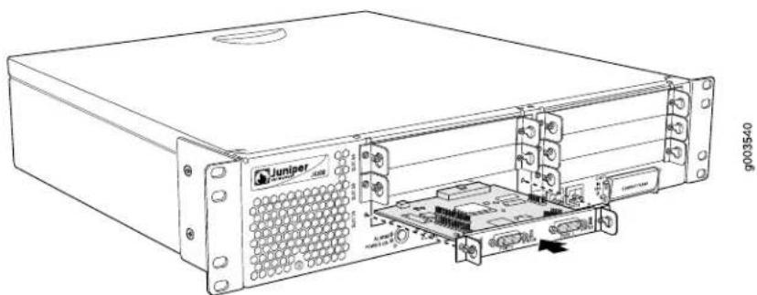
natural_image
Technical line drawing of a Juniper server rack with internal components and connectors (no text or symbols)To install a PIM (see Figure 57):
- Attach an electrostatic discharge (ESD) grounding strap to your bare wrist and connect the strap to the ESD point on the chassis, or to an outside ESD point if the Services Router is disconnected from earth ground. For more information about ESD, see "Preventing Electrostatic Discharge Damage" on page 209.
-
Press and release the power button to power off the router. Verify that the POWER LED blinks and then turns off.
-
Align the notches in the connector at the rear of the PIM with the notches in the PIM slot in the Services Router, and slide the PIM in until it lodges firmly in the router.
!
CAUTION: Slide the PIM straight into the slot to avoid damaging the components on the PIM.
- Tighten the captive screws on each side of the PIM faceplate.
- Insert the appropriate cables into the cable connectors on the PIM.
- If necessary, arrange the cables to prevent them from dislodging or developing stress points:
■Secure each cable so that it is not supporting its own weight as it hangs to the floor.
■Place excess cable out of the way in a neatly coiled loop.
■Use fasteners to maintain the shape of cable loops.
-
Press and release the power button to power on the router. Verify that the POWER LED lights steadily after you press the power button.
-
Verify that the PIM LEDs light steadily green to confirm that the PIM and its ports are online and operational. For more information about PIM LEDs, see "Field-Replaceable PIMs" on page 47.
You can also verify correct PIM functioning by issuing the show chassis fpc pic-status command described in the JUNOS System Basics and Services Command Reference.
[Non-Text]
NOTE: In the show chassis fpc pic-status command, the PIM slot number is reported as an FPC number and the PIM number (always 0) is reported as a PIC number.
- Complete the initial configuration of each network interface by using the CLI or J-Web interface. For information about configuring network interfaces, see the J-series Services Router Basic LAN and WAN Access Configuration Guide.
Replacing PIM Cables
Removing and installing PIM cables does not affect Services Router function, except that a PIM does not receive or transmit data while its cable is disconnected. To replace a PIM cable, perform the following procedures:
■Removing a PIM Cable on page 160
■Installing a PIM Cable on page 160
Removing a PIM Cable
To remove a PIM cable:
- If you are removing all cables connected to the PIM, issue the following CLI command to take the PIM offline:
user@host> request chassis pic fpc-slot pim-slot pic-slot 0 offline
For example, to take the PIM in slot 4 offline, enter the following command:
user@host> request chassis pic fpc-slot 4 pic-slot 0 offline
For more information about the command, see the JUNOS System Basics and Services Command Reference.
- Unplug the cable from the cable connector port.
- Detach the cable from the destination port.
Installing a PIM Cable
To install a PIM cable:
- Have ready a length of the type of cable used by the PIM. For cable specifications, see "Network Cable Specifications and Connector Pinouts" on page 189.
- Insert the cable connector into the cable connector port on the PIM faceplate.
- Arrange the cable as necessary to prevent it from dislodging or developing stress points:
■Secure the cable so that it is not supporting its own weight as it hangs to the floor.
■Place excess cable out of the way in a neatly coiled loop.
■Use fasteners to maintain the shape of cable loops.
- Insert the other end of the cable into the destination port.
- Repeat the previous steps for any additional cables.
- If the PIM is offline (its status LED is steadily red), issue the following CLI command to bring the PIM online:
user@host> request chassis pic fpc-slot pim-slot pic-slot 0 online
For example, to bring the PIM in slot 4 online, enter the following command:
user@host> request chassis pic fpc-slot 4 pic-slot 0 online
For more information about the command, see the JUNOS System Basics and Services Command Reference.
- Verify that the PIM status LED shines steadily green to confirm that the PIM is online.
You can also verify correct PIM functioning by issuing the show chassis fpc pic-status command described in the JUNOS System Basics and Services Command Reference.

NOTE: In the show chassis fpc pic-status command, the PIM slot number is reported as an FPC number and the PIM number (always 0) is reported as a PIC number.
Removing and Installing the Primary Compact Flash Disk
The primary compact flash drive is located in a slot at the rear of the Services Router as shown in Figure 2, Figure 8, and Figure 10. The primary compact flash disk provides primary storage for the router. It can accommodate software images, configuration files, and microcode.
For information about configuring the primary compact flash disk, see the J-series Services Router Administration Guide.
To remove and install a primary compact flash disk, perform the following procedures:
■Removing the Primary Compact Flash Disk on page 161
■Installing the Primary Compact Flash Disk on page 162
Removing the Primary Compact Flash Disk
To remove the primary compact flash disk (see Figure 58):
-
Place an electrostatic bag or antistatic mat on a flat, stable surface.
-
Attach an electrostatic discharge (ESD) grounding strap to your bare wrist and connect the strap to the ESD point on the chassis, or to an outside ESD point if the router is disconnected from earth ground. For more information about ESD, see the Getting Started Guide for your model.
-
Press and release the power button to power off the router. Wait for the POWER LED to turn off.
-
Remove the power cord from the power supply.
-
Loosen the thumbscrew that secures the primary compact flash drive cover on the rear of the chassis.
-
Remove the compact flash drive cover.
-
Gently grasp the compact flash disk, and slide it out of the connector (see Figure 58).
- Place the compact flash disk on the antistatic mat or in the electrostatic bag.
Figure 58: Removing the Primary Compact Flash Disk

natural_image
Technical line drawing of a device rear panel with ports and connectors (no text or symbols)Installing the Primary Compact Flash Disk
To install the primary compact flash disk (see Figure 59):

NOTE: If you plan to boot the Services Router from the primary compact flash disk, you must first configure the primary compact flash disk in another router or with a computer running UNIX or Cygwin. For more information, see the J-series Services Router Administration Guide.
- Attach an electrostatic discharge (ESD) grounding strap to your bare wrist and connect the strap to the ESD point on the chassis, or to an outside ESD point if the router is disconnected from earth ground. For more information about ESD, see the Getting Started Guide for your model.
- Press and release the power button to power off the router. Wait for the POWER LED to turn off.
- Remove the power cord from the power supply.
- Loosen the thumbscrew that secures the primary compact flash drive cover on the rear of the chassis.
- Remove the compact flash drive cover.
- Slide the compact flash disk into the connector on the Routing Engine (see Figure 59).
- Replace the compact flash drive cover.
-
Tighten the thumbscrew that secures the compact flash drive cover to the rear of the chassis.
-
Plug the power cord into the power supply.
- Press and release the power button to power on the router. Verify that the POWER LED lights steadily after you press the power button.
Figure 59: Installing the Primary Compact Flash Disk

natural_image
Technical line drawing of a server rack with ports and an internal connector (no text or symbols)Removing and Installing the Removable Compact Flash Disk
The removable compact flash disk is an optional component on J4300 and J6300 Services Routers. The removable compact flash disk provides secondary storage for the router. It can accommodate software images, configuration files, and microcode. If the primary compact flash disk fails on startup, the router boots from the removable compact flash disk.
For information about configuring the removable compact flash disk, see the J-series Services Router Administration Guide.
To remove and install a removable compact flash disk, perform the following procedures:
■Removing the Removable Compact Flash Disk on page 163
■Installing the Removable Compact Flash Disk on page 164
Removing the Removable Compact Flash Disk

NOTE: Depending on your configuration, the Services Router might not have a backup compact flash drive. If no backup compact flash drive is installed, proceed directly to the next section, "Installing the Removable Compact Flash Disk" on page 164.
The removable compact flash drive is located in a slot on the front panel of the Services Router. To remove the removable compact flash disk (see Figure 60):
- Place an electrostatic bag or antistatic mat on a flat, stable surface.
-
Attach an electrostatic discharge (ESD) grounding strap to your bare wrist and connect the strap to the ESD point on the chassis, or to an outside ESD point if the router is disconnected from earth ground. For more information about ESD, see "Preventing Electrostatic Discharge Damage" on page 209.
-
Verify the CF REMOVE LED is off.
If the CF REMOVE LED is on, the router might have booted from the removable compact flash disk.
To see which device the router used to boot, issue the show system storage command from the CLI. For example:
user@host> show system storage
| Filesystem /dev/ad0s1a | 512-blocks 218254 | Used 175546 | Avail Capacity Mounted on 40526 81% / |
| ... |
The boot device is mounted on /. The primary compact flash disk is located at ad0. The removable compact flash disk is located at ad2. The USB storage device is located at usb0. This example shows that the router booted from the primary compact flash disk.
- If the show system storage output indicates that the router booted from the removable compact flash disk, press and release the power button to power off the router. Wait for the POWER LED to turn off before you remove the compact flash drive.
- Slide the compact flash drive door up to unlatch the door, then tilt the top of the door out (see Figure 60).
- Eject the removable compact flash disk by pressing the button to the left of the compact flash drive once to unlock the button, and again to eject the compact flash drive.
- Gently grasp the compact flash disk, and slide it out of the connector.
- Place the compact flash disk on the antistatic mat or in the electrostatic bag.
Figure 60: Removing the Removable Compact Flash Disk
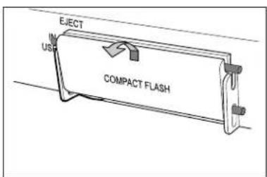

g003533
Installing the Removable Compact Flash Disk
To install the removable compact flash disk, follow this procedure (see Figure 61):
- Attach an electrostatic discharge (ESD) grounding strap to your bare wrist and connect the strap to the ESD point on the chassis, or to an outside ESD point if the router is disconnected from earth ground. For more information about ESD, see "Preventing Electrostatic Discharge Damage" on page 209.
- Slide the compact flash door up to unlatch the door, then tilt the top of the door out (see Figure 61).
- Slide the compact flash disk into the connector on the Routing Engine.
- Tilt the compact flash door in, and slide it down until it is secured.
- To configure the removable compact flash disk with the request system snapshot command, see the J-series Services Router Administration Guide.
Figure 61: Installing the Removable Compact Flash Disk


g003534
Removing and Installing the USB Storage Device
USB storage devices are optional components on J-series Services Routers. If installed, a USB storage device provides secondary storage for the router. It can accommodate software images, configuration files, and microcode. If the primary compact flash disk fails on startup, and the removable compact flash disk is not installed or fails, the router boots from the USB storage device.
For information about configuring the USB storage device, see the J-series Services Router Administration Guide.

NOTE: For a list of supported USB storage devices, see the J-series Services Router Release Notes at http://www.juniper.net.
To remove and install a USB storage device, perform the following procedures:
■Removing the USB Storage Device on page 166
■Installing the USB Storage Device on page 166
Removing the USB Storage Device

NOTE: Depending on your configuration, the Services Router might not have a USB storage device. If no USB storage device is installed, proceed directly to the next section, "Installing the USB Storage Device" on page 166.
The USB storage device is installed into the USB port on the front panel of the Services Router. To remove the USB storage device:
- Place an electrostatic bag or antistatic mat on a flat, stable surface.
- Attach an electrostatic discharge (ESD) grounding strap to your bare wrist and connect the strap to the ESD point on the chassis, or to an outside ESD point if the router is disconnected from earth ground. For more information about ESD, see "Preventing Electrostatic Discharge Damage" on page 209.
- Verify that the router did not boot from the USB storage device by issuing the show system storage command from the CLI. For example:
user@host> show system storage
| Filesystem | 512-blocks | Used | Avail Capacity Mounted on | |
| /dev/ad0s1a | 218254 | 175546 | 40526 | 81% / |
...
The boot device is mounted on /. The primary compact flash disk is located at ad0. The removable compact flash disk is located at ad2. . The USB storage device is located at da0. This example shows that the router booted from the primary compact flash disk.
- If the show system storage output indicates that the router booted from the USB storage device, press and release the power button to power off the router. Wait for the POWER LED to turn off before you remove the USB storage device.
- Gently grasp the USB storage device and slide it out of the USB port.
- Place the USB storage device on the antistatic mat or in the electrostatic bag.
Installing the USB Storage Device
To install the USB storage device:

NOTE: For a list of supported USB storage devices, see the J-series Services Router Release Notes at http://www.juniper.net.
- Attach an electrostatic discharge (ESD) grounding strap to your bare wrist and connect the strap to the ESD point on the chassis, or to an outside ESD point if the router is disconnected from earth ground. For more information about ESD, see "Preventing Electrostatic Discharge Damage" on page 209.
- Orient the USB storage device with the USB port on the front panel of the router.
- Insert the USB storage device into the USB port. If the USB storage device does not easily slide into the port, it might not be oriented correctly. Turn the USB storage device upside-down and try again.
- To configure the USB storage device with the request system snapshot command, see the J-series Services Router Administration Guide.
Removing and Installing DRAM Modules
The DRAM installed on the Routing Engine provides storage for the routing and forwarding tables and for other Routing Engine processes. The design of the Routing Engine allows you to modify the DRAM configuration by adding DRAM modules to the Routing Engine board, or removing DRAM modules from the board.
The DRAM modules are located on the top of the Routing Engine, as shown in Figure 62 and Figure 63.

NOTE: Use only DRAM modules purchased through Juniper Networks specifically for your model. Also, DRAM modules are not always transferable across J-series platforms. You can transfer a DRAM module between a J4300 and a J6300 Services Router, but not between these models and any other Services Router.
Figure 62: J2300 DRAM Location

Figure 63: J4300 and J6300 DRAM Location
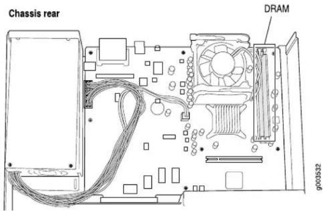
To modify the DRAM configuration, use the following procedures:
■Removing a DRAM Module on page 168
■Installing a DRAM Module on page 169
Removing a DRAM Module

NOTE: Depending on your configuration, the Services Router might have an empty DRAM socket. If you are adding a DRAM module to the DRAM configuration, proceed directly to "Installing a DRAM Module" on page 169.
To remove a DRAM module:
-
Place an electrostatic bag or antistatic mat on a flat, stable surface.
-
Attach an electrostatic discharge (ESD) grounding strap to your bare wrist and connect the strap to the ESD point on the chassis, or to an outside ESD point if the router is disconnected from earth ground. For more information about ESD, see the Getting Started Guide for your router.
-
Press and release the power button to power off the router. Wait for the POWER LED to turn off.
-
Unplug the power cord or cable from the power source receptacle.
-
Remove the screws from the sides and top of the chassis that secure the cover to the chassis.
-
Slide the cover off the chassis.
-
To release the DRAM module, press the plastic ejectors on both sides of the module (see Figure 64 or Figure 65).
-
Grasp the DRAM module, being careful not to touch any electrical components on the module, and firmly pull it out of the slot on the Routing Engine.
- Place the DRAM module on the antistatic mat or in the electrostatic bag.
Figure 64: Adding or Replacing a DRAM Module in a J2300 Chassis


g003509
Figure 65: Adding or Replacing a DRAM Module in a J4300 or J6300 Chassis


g003531
Installing a DRAM Module
To install a DRAM module onto the Routing Engine:
- Take the following steps if you have not already done so:
a. Attach an electrostatic discharge (ESD) grounding strap to your bare wrist and connect the strap to the ESD point on the chassis, or to an outside ESD point if the router is disconnected from earth ground. For more information about ESD, see the Getting Started Guide for your router.
b. Press and release the power button to power off the router. Wait for the POWER LED to turn off.
c. Unplug the power cord or cable from the power source receptacle.
d. Remove the screws from the sides and top of the chassis that secure the cover to the chassis.
e. Slide the cover off the chassis.
- Remove the DRAM module from its electrostatic bag.
- To open the empty DRAM socket, press the plastic ejectors on both sides (see Figure 64 or Figure 65).
- Grasp the DRAM module by the edges, being careful not to touch any electrical components.
- Pressing firmly on both ends, push the module into the socket until the ejectors click into the closed position (see Figure 64 or Figure 65).
- Slide the cover onto the chassis.
- Replace and tighten the screws on the sides and top of the chassis that secure the cover to the chassis.
- Replace the power cord or cable.
- Press and release the power button to power on the router. Verify that the POWER LED lights steadily after you press the power button.
- To view the DRAM configuration and verify that it was installed correctly, issue the show chassis routing-engine command, described in the JUNOS System Basics and Services Command Reference. This command shows the total memory installed.
Replacing Power System Components
The power cords on all Services Routers are replaceable.
You can add a second power supply to the J6300 Services Router that is of the same type as the first (either AC or DC).
The power supplies are located at the right rear of the chassis (see Figure 10 or Figure 11). Each J6300 power supply provides power to all components in the router. The J6300 power supplies are fully redundant. If one power supply fails or is removed, the remaining power supply instantly assumes the entire electrical load. One power supply can provide full power for as long as the router is operational.
Each J6300 power supply is hot-insertable and hot-removable.

CAUTION: Do not leave a power supply slot empty for more than a short time while the Services Router is operational. The power supply or a blank power supply panel must remain in the chassis for proper airflow.
To replace power system components, use the following procedures:
■Replacing an AC Power Supply Cord on page 171
■Removing an AC Power Supply from a J6300 Router on page 172
■Installing an AC Power Supply in a J6300 Router on page 173
■Replacing a DC Power Supply Cable on page 174
■Removing a DC Power Supply on page 175
■Installing a DC Power Supply on page 176
Replacing an AC Power Supply Cord
To replace the AC power cord for a redundant power supply:
- Locate a replacement power cord with the type of plug appropriate for your geographical location (see "AC Power, Connection, and Power Cord Specifications" on page 87).
- Attach an electrostatic discharge (ESD) grounding strap to your bare wrist and connect the strap to the ESD point on the chassis, or to an outside ESD point if the router is disconnected from earth ground. For more information about ESD, see "Preventing Electrostatic Discharge Damage" on page 209.
- Press and release the power button to power off the router. Wait for the POWER LED to turn off.

NOTE: If the power supply is a redundant power supply in a J6300 Services Router, you can leave the router powered on and power flowing in the alternate power supply.
- Unplug the power cord from the power source receptacle.
- Unplug the power cord from the appliance inlet on the power supply faceplate.
- Insert the appliance coupler end of the replacement power cord into the appliance inlet on the power supply faceplate.
- Insert the power cord plug into an AC power source receptacle.

NOTE: Each power supply must be connected to a dedicated AC power feed. For information about connecting to AC power sources, see “Connecting Power” on page 98.
- Verify that the power cord does not block access to Services Router components or drape where people might trip on it.
- Press and release the power button to power on the router. Verify that the POWER LED lights steadily after you press the power button.
Removing an AC Power Supply from a J6300 Router
The power supplies are located at the right rear of the chassis. A power supply weighs 2.4 lb (1.1 kg).
To remove an AC power supply from a J6300 Services Router (see Figure 66):
- Attach an electrostatic discharge (ESD) grounding strap to your bare wrist and connect the strap to the ESD point on the chassis, or to an outside ESD point if the router is disconnected from earth ground. For more information about ESD, see "Preventing Electrostatic Discharge Damage" on page 209.
- Press and release the power button to power off the Services Router. Wait for the POWER LED to turn off.

NOTE: If the power supply is a redundant power supply in a J6300 Service Router, you can leave the router powered on and power flowing in the alternate power supply.
- Unplug the power cord from the power source receptacle.
- Unplug the power cord from the appliance inlet on the power supply faceplate.
- Slide the ejector tab on the power supply faceplate to the right and hold it in place to unlock the power supply.
- Grasp the handle on the power supply faceplate, and pull firmly to start removing the power supply. Slide it halfway out of the chassis (see Figure 66).
- Place one hand underneath the power supply to support it and slide it completely out of the chassis.
- If you are not reinstalling a power supply into the emptied slot, install a blank power supply panel over the slot.
Figure 66: Removing an AC Power Supply

natural_image
Technical line drawing of an internal device with connectors and ports, no text or symbols presentInstalling an AC Power Supply in a J6300 Router
To install an AC power supply in a J6300 Services Router (see Figure 67):
-
Attach an electrostatic discharge (ESD) grounding strap to your bare wrist and connect the strap to the ESD point on the chassis, or to an outside ESD point if the router is disconnected from earth ground. For more information about ESD, see "Preventing Electrostatic Discharge Damage" on page 209.
-
Using both hands, slide the power supply into the chassis until you feel resistance.
-
Firmly push the power supply into the chassis until it comes to a stop. Make sure that the power supply faceplate is flush with any adjacent power supply faceplate.
-
Insert the appliance coupler end of a power cord into the appliance inlet on the power supply faceplate.
-
Insert the power cord plug into an AC power source receptacle.

NOTE: Each power supply must be connected to a dedicated AC power feed. For information about connecting to AC power sources, see "Connecting Power" on page 98.
-
Verify that the power cord does not block access to router components or drape where people might trip on it.
-
Press and release the power button to power on the router. Verify that the POWER LED lights steadily after you press the power button.
Figure 67: Installing an AC Power Supply

natural_image
Technical line drawing of an internal server or rack unit with connectors and ventilation slots (no text or symbols)Replacing a DC Power Supply Cable
To replace a power cable for a DC power supply:
- Locate a replacement power cable and a lug that meet the specifications defined in "Chassis Grounding" on page 98 and "DC Power, Connection, and Power Cable Specifications" on page 88.
!
CAUTION: A licensed electrician must attach a cable lug to the power cable that you supply. A cable with an incorrectly attached lug can damage the router (for example, by causing a short circuit).
- Attach an electrostatic discharge (ESD) grounding strap to your bare wrist and connect the strap to the ESD point on the chassis, or to an outside ESD point if the router is disconnected from earth ground. For more information about ESD, see "Preventing Electrostatic Discharge Damage" on page 209.
- Press and release the power button to power off the Services Router. Wait for the POWER LED to turn off.
- Ensure that the voltage across the DC power source cable leads is 0 V and that the cable leads cannot become active during installation.
!
CAUTION: There is no standard color coding for DC power cables. The color coding used by the external DC power source at your site determines the color coding for the leads on the power cables that attach to the terminal studs on each power supply. You must ensure that power connections maintain the proper polarity. The power source cables might be labeled (+) and (−) to indicate their polarity.
- Remove the power cable from the DC power source.
-
Use a Phillips screwdriver to remove the clear plastic cover protecting the terminal block.
-
Within the terminal block, remove the screw that fastens the power cable lug to the terminal block.
- Carefully move the power cable out of the way.
- Using the removed screw, secure the replacement power cable to the appropriate terminal. Tighten the screw until snug. Do not overtighten.
The screw contains a captive washer used to secure the power cable lug to the terminal block.

NOTE: Each power supply must be connected to a dedicated DC power feed. For information about connecting to DC power sources, see “Connecting Power” on page 98.
- Dress the power cable appropriately.
- Replace the clear plastic cover over the terminal block.
- Verify that the power cable does not block access to router components or drape where people might trip on it.
- Press and release the power button to power on the router. Verify that the POWER LED lights steadily after you press the power button.
Removing a DC Power Supply
The power supplies are located at the right rear of the chassis. A power supply weighs 2.4 lb (1.1 kg).
To remove a DC power supply (see Figure 68):
- Attach an electrostatic discharge (ESD) grounding strap to your bare wrist and connect the strap to the ESD point on the chassis, or to an outside ESD point if the router is disconnected from earth ground. For more information about ESD, see “Preventing Electrostatic Discharge Damage” on page 209.
- Press and release the power button to power off the Services Router. Wait for the POWER LED to turn off.
- Ensure that the voltage across the DC power source cable leads is 0 V and that the cable leads cannot become active during installation.

CAUTION: There is no standard color coding for DC power cables. The color coding used by the external DC power source at your site determines the color coding for the leads on the power cables that attach to the terminal studs on each power supply. You must ensure that power connections maintain the proper polarity. The power source cables might be labeled (+) and (−) to indicate their polarity.
-
Remove the power cables from the DC power source.
-
Use a Phillips screwdriver to remove the clear plastic cover protecting the terminal block.
- Within the terminal block, remove the screws that fasten the power cable lugs to the terminal block.
- Carefully move the power cables out of the way.
- Slide the ejector tab on the power supply faceplate to the right, and hold it in place to unlock the power supply.
- Grasp the handle on the power supply faceplate, and pull firmly to start removing the power supply. Slide it halfway out of the chassis (see Figure 68).
- Place one hand underneath the power supply to support it, and slide it completely out of the chassis.
- If you are not reinstalling a power supply into the emptied slot, install a blank power supply panel over the slot.
Figure 68: Removing a DC Power Supply

natural_image
Technical line drawing of an electronic device showing internal components and wiring (no text or symbols)Installing a DC Power Supply
Each power supply in a DC-powered router must be connected to earth ground. A ground terminal is provided on each DC power supply for this purpose.
To install a DC power supply (see Figure 69):
- Ensure that the voltage across the DC power source cable leads is 0 V and that the cable leads cannot become active during installation.
!
CAUTION: There is no standard color coding for DC power cables. The color coding used by the external DC power source at your site determines the color coding for the leads on the power cables that attach to the terminal studs on each power supply. You must ensure that power connections maintain the proper polarity. The power source cables might be labeled (+) and (−) to indicate their polarity.
- Attach an electrostatic discharge (ESD) grounding strap to your bare wrist and connect the strap to the ESD point on the chassis, or to an outside ESD point if the router is disconnected from earth ground. For more information about ESD, see “Preventing Electrostatic Discharge Damage” on page 209.
- Using both hands, slide the power supply into the chassis until you feel resistance.
- Firmly push the power supply into the chassis until it comes to a stop. Make sure that the power supply faceplate is flush with any adjacent power supply faceplate.
- Use a Phillips screwdriver to remove the clear plastic cover protecting the terminal block.
- Within the terminal block, remove the two center screws next to the labels -48 VDC and RTN.
Each screw contains a captive washer to secure a power cable lug to the terminal block. - Using one of the removed screws, secure the positive (+) DC source power cable lug to the RTN terminal. Tighten the screw until snug. Do not overtighten. Apply between 8 lb-in. (0.9 Nm) and 9 lb-in. (1.02 Nm) of torque to the screw.
- Using the other removed screw, secure the negative (−) DC source power cable lug to the -48 VDC terminal. Tighten the screw until snug. Do not overtighten. Apply between 8 lb-in. (0.9 Nm) and 9 lb-in. (1.02 Nm) of torque to the screw.
[Non-Text]
NOTE: Each power supply must be connected to a dedicated DC power feed. For information about connecting to DC power sources, see “Connecting Power” on page 98.
- Dress the power cables appropriately.
- Replace the clear plastic cover over the terminal block.
- Verify that the power cord does not block access to router components or drape where people might trip on it.
- Press and release the power button to power on the router. Verify that the POWER LED lights steadily after you press the power button.
Figure 69: Installing a DC Power Supply
![Juniper J2300 - [Non-Text] - 1](/content/2026/05/1054098/images/cfc556c3fb76c69b8cf7d003b499c4063150cb6ebd5bfa7b1315909f40b9275e.jpg)
natural_image
Technical line drawing of an electronic device showing internal components and wiring (no text or symbols)Troubleshooting Hardware Components
This section provides an overview of the resources you can use to troubleshoot hardware problems on the Services Router:
■Chassis Alarm Conditions on page 178
■ Contacting the Juniper Networks Technical Assistance Center on page 180
Chassis Alarm Conditions
When the Routing Engine detects an alarm condition, it lights the ALARM LED on the front panel. When the condition is corrected, the light turns off.

NOTE: The ALARM LED on the Services Router lights yellow whether the alarm condition is major (red) or minor (yellow).
To view a more detailed description of the alarm cause, issue the show chassis alarms CLI command:
user@host> show chassis alarms
Table 58 on page 179 describes alarms that can occur for a chassis component such as the Routing Engine or a Physical Interface Module (PIM).
Table 58: Chassis Alarm Conditions and Corrective Actions
| Alarm SeverityCorrective ActionAlarm Condi | |||
| Alternative boot media | The Services Router boots from an alternative boot device. | primary compact flash disk. If you configured your router to boot from an alternative boot device, ignore this alarm condition.If you did not configure the router to boot from an alternative boot device, contact JTAC. (See “Requesting Support” on page xxi.) | Yellow (minor)Typically, the router boots fron |
| PIM | A PIM has failed.When a PIM fails, it attempts to reboot. If the Routing Engine detects that a PIM is rebooting too often, it shuts down the PIM. | “Replacing a PIM” on page 156.) | Red (major)Replace the failed PIM. (See |
| Routing Engine | An error occurred during the process of reading or writing compact flash. | install a bootable image. (See the J-series Services Router Administration Guide.)If this remedy fails, you must replace the failed Routing Engine. To contact JTAC, see “Requesting Support” on page xxi. | Yellow (minor)Reformat the compact flash an |
| Routing Engine temperature is too warm. | Check the room temperature. (See “Router Environmental Tolerances” on page 83.)Check the air flow. (See “General Site Guidelines” on page 81.)Check the fans. (See “J2300 Cooling System” on page 20 or “J4300 and J6300 Cooling System” on page 30.) If you must replace a fan or the Routing Engine, contact JTAC. (See “Requesting Support” on page xxi.) | Yellow (minor) | |
| Routing Engine fan has failed. | JTAC, see “Requesting Support” on page xxi. | Red (major)Replace the failed fan. To contact | |
Contacting the Juniper Networks Technical Assistance Center
If you need assistance while troubleshooting a Services Router, open a support case using the Case Manager link at http://www.juniper.net/support/, or call 1-888-314-JTAC (within the United States) or 1-408-745-9500 (from outside the United States).
Chapter 12
Contacting Customer Support and Returning Hardware
This chapter describes how to return the Services Router or individual components to Juniper Networks for repair or replacement. It contains the following topics:
■Locating Component Serial Numbers on page 181
■Contacting Customer Support on page 183
■Return Procedure on page 184
■Packing a Router or Component for Shipment on page 185
Locating Component Serial Numbers
Before contacting Juniper Networks to request a Return Materials Authorization (RMA), you must find the serial number on the router or component. To list the router components and their serial numbers, enter the following command-line interface (CLI) command:
user@host> show chassis hardware
| Hardware inventory: | ||||
| Item | Version | Part number | Serial number | Description |
| Chassis | 015810200500 | J6350 | ||
| Midplane | REV 00 | 710-012339 | ||
| System IO | REV 00 | 710-012315 | JX350 System IO | |
| Routing Engine | REV 00 | 710-012151 | RE-J6350-3400 | |
| HW crypto | Crypto accelerator | |||
| FPC 0 | FPC | |||
| PIC 0 | 4x GE Base | |||
| PIC | ||||

NOTE: In the show chassis hardware command, the PIM slot number is reported as an FPC number and the PIM number (always 0) is reported as the PIC number.
Most components also have a serial number ID label (see Figure 70 through Figure 72) attached to the component body.
Figure 70: J2300 Serial Number ID Label
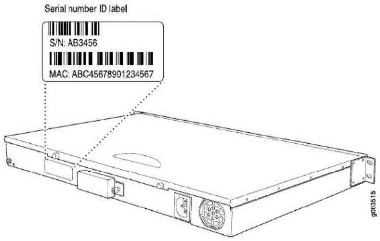
Figure 71: J4300 Serial Number ID Label
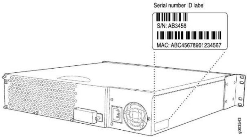
Figure 72: J6300 Serial Number ID Label
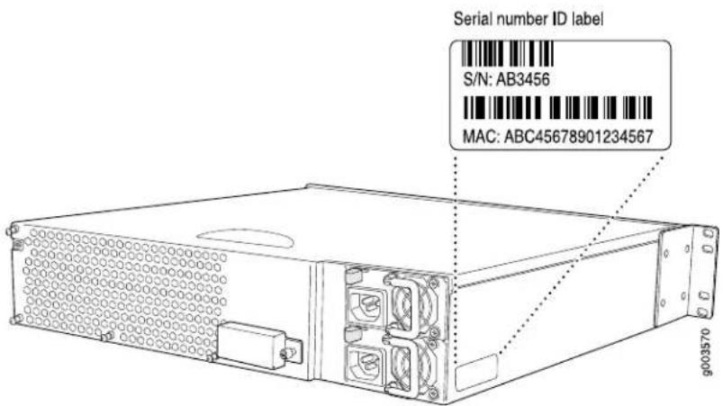
The following sections describe the label location on each type of component:
■PIM Serial Number Label on page 183
■J6300 Power Supply Serial Number Labels on page 183
PIM Serial Number Label
PIMs are field-replaceable. Each PIM has a unique serial number. The serial number label is located on the right side of the PIM, when the PIM is horizontally oriented (as it would be installed in the router). The exact location may be slightly different on different PIMs, depending on the placement of components on the PIM board.
J6300 Power Supply Serial Number Labels
The power supplies installed in the J6300 Services Router are field-replaceable. Each power supply has a unique serial number. The serial number label is located on the top of the power supply.
Contacting Customer Support
After you have located the serial numbers of the components you need to return, contact Juniper Networks Technical Assistance Center (JTAC) in one of the following ways.
You can contact JTAC 24 hours a day, seven days a week.
■ On the Web, using the Case Manager link at http://www.juniper.net/support/
■By telephone:
From the US and Canada: 1-888-314-JTAC
From all other locations: 1-408-745-9500
If contacting JTAC by telephone, enter your 11-digit case number followed by the pound (#) key if this is an existing case, or press the star (*) key to be routed to the next available support engineer.
Information You Might Need to Supply to JTAC
When requesting support from JTAC by telephone, be prepared to provide the following information:
■Your existing case number, if you have one
■Details of the failure or problem
■Type of activity being performed on the router when the problem occurred
■ Configuration data displayed by one or more show commands
Return Procedure
If the problem cannot be resolved by the JTAC technician, an RMA number is issued. This number is used to track the returned material at the factory and to return repaired or new components to the customer as needed.

NOTE: Do not return any component to Juniper Networks unless you have first obtained an RMA number. Juniper Networks reserves the right to refuse shipments that do not have an RMA. Refused shipments will be returned to the customer via collect freight.
For more information about return and repair policies, see the customer support Web page at http://www.juniper.net/support/guidelines.html.
For product problems or technical support issues, open a support case using the Case Manager link at http://www.juniper.net/support/, or call 1-888-314-JTAC (within the United States) or 1-408-745-9500 (outside the United States).
When you need to return a component, follow this procedure:
- Determine the part number and serial number of the component. For instructions, see "Locating Component Serial Numbers" on page 181.
- Obtain a Return Materials Authorization (RMA) number from the Juniper Networks Technical Assistance Center (JTAC). You can send e-mail or telephone as described above.
- Provide the following information in your e-mail message or during the telephone call:
■Part number and serial number of component
■Your name, organization name, telephone number, and fax number
■Description of the failure
-
The support representative validates your request and issues an RMA number for return of the component.
-
Pack the router or component for shipment, as described in "Packing a Router or Component for Shipment" on page 185.
Packing a Router or Component for Shipment
This section contains the following topics:
■Tools and Parts Required on page 185
■Packing the Services Router for Shipment on page 185
■Packing Components for Shipment on page 186
Tools and Parts Required
To remove components from the router or the router from a rack, you need the following tools and parts:
■Blank panels to cover empty slots
■Electrostatic bag or antistatic mat, for each component
■Electrostatic discharge (ESD) grounding wrist strap
■Flat-blade screwdriver, approximately 1/4 in. (6 mm)
■Phillips (+) screwdrivers, numbers 1 and 2
Packing the Services Router for Shipment
To pack the router for shipment, follow this procedure:
- Retrieve the shipping carton and packing materials in which the router was originally shipped. If you do not have these materials, contact your Juniper Networks representative about approved packaging materials.
- Attach an electrostatic discharge (ESD) grounding strap to your bare wrist and connect the strap to the ESD point on the chassis, or to an outside ESD point if the router is disconnected from earth ground. For more information about ESD, see "Preventing Electrostatic Discharge Damage" on page 209.
- On the console or other management device connected to the master Routing Engine, enter CLI operational mode and issue the following command to shut down the router software.
user@host> request system halt
Wait until a message appears on the console confirming that the operating system has halted. For more information about the command, see the J-series Services Router Administration Guide.
- Shut down power to the router by pressing the power button on the front panel of the router.
- Disconnect power from the router. For instructions, see "Replacing an AC Power Supply Cord" on page 171.
- Remove the cables that connect to all external devices. For instructions, see "Removing a PIM Cable" on page 160.
- Remove all field-replaceable units (FRUs) from the router.
- If the router is installed on a wall or rack, have one person support the weight of the router, while another person unscrews and removes the mounting screws.
- Place the router in the shipping carton.
- Cover the router with an ESD bag, and place the packing foam on top of and around the router.
- Replace the accessory box on top of the packing foam.
- Securely tape the box closed.
- Write the RMA number on the exterior of the box to ensure proper tracking.
Packing Components for Shipment
To pack and ship individual components, follow these guidelines:
■When you return components, make sure they are adequately protected with packing materials and packed so that the pieces are prevented from moving around inside the carton.
■Use the original shipping materials if they are available.
■Place individual boards in electrostatic bags.
■Write the RMA number on the exterior of the box to ensure proper tracking.

CAUTION: Do not stack any of the router components.
Part 4
J-series Requirements and Specifications
■Network Cable Specifications and Connector Pinouts on page 189
■Safety and Regulatory Compliance Information on page 205
J2300, J4300, and J6300 Services Router Getting Started Guide
Chapter 13
Network Cable Specifications and Connector Pinouts
The network interfaces supported on the router accept different kinds of network cable.
■Serial PIM Cable Specifications on page 189
■RJ-45 Connector Pinout for Fast Ethernet Ports on page 199
■Chassis Console Port Pinouts on page 199
■E1 and T1 RJ-48 Cable Pinouts on page 200
■E3 and T3 BNC Connector Pinout on page 203
■ADSL and G.SHDSL RJ-11 Connector Pinout on page 203
■ISDN RJ-45 Connector Pinout on page 204
Serial PIM Cable Specifications
The 2-port serial PIM uses the cables and connectors summarized in Table 59 on page 189. Pinouts are detailed in Table 60 on page 190 through Table 69 on page 198.
Table 59: 2-Port Serial PIM Cables and Connectors
| End-to-End ConductorsConnector Hardware ConnectorName | ||
| DB-25 maleRS-232 DTE jackscrews | Table 60 on page 190134-40 threaded | |
| Table 61 on page 191134-40 threaded jack | ||
| DTE | DC-37 (DB-37) maleRS-422/449 (EIA-449) jackscrews | Table 62 on page 191254-40 threaded |
| DCE | Table 63 on page 192254-40 threaded jack | |
| DB-25 maleEIA-530A DTE jackscrews | Table 64 on page 194234-40 threaded | |
Table 59: 2-Port Serial PIM Cables and Connectors (continued)
| End-to-End Conductors Connector Hindute Connector Name | |||
| Table 65 on page 195224-40 threaded jack | |||
| M/34 maleV.35 DTE | included with M/34 connector shell) | Table 66 on page 19618Standard (Normall | |
| M/34 femaleV.35 DCE | included with M/34 connector shell) | Table 67 on page 19718Standard (Normall | |
| X.21 DTE | DB-15 male | M3 threaded jackscrews 13 | Table 68 on page 197 |
| Table 69 on page 19813M3 threaded jack | |||
RS-232 DTE Cable Pinout
Table 60: RS-232 DTE Cable Pinout
| DescriptionLFH-60 PairingDB-25 PinLFH-60 Pin | |||
| Frame Ground-115 | |||
| Transmit Data-260 | |||
| -31 | Receive Data | ||
| -448 | Request to Send | ||
| -537 | Clear to Send | ||
| -69 | Data Set Ready | ||
| -757 | Signal Ground | ||
| -813 | Data Carrier Detect | ||
| 56 | Transmit Clock-15 | ||
| 5 | 17 | - | Receive Clock |
| 41 | 18 | - | Local Loopback |
| 33 | 20 | - | Data Terminal Ready |
| 52 | Terminal Clock-24 | ||
| --22 to 21 | - | ||
| --18 to 17 | - | ||
RS-232 DCE Cable Pinout
Table 61: RS-232 DCE Cable Pinout
| DescriptionLFH-60 PairingDB-25 PinLFH-60 Pin | |
| Frame Ground-115 | |
| Transmit Data-21 | |
| Receive Data-360 | |
| Request to Send-437 | |
| Clear to Send-548 | |
| Data Set Ready-633 | |
| Signal Ground-757 | |
| Data Carrier Detect-813 | |
| Transmit Clock-1556 | |
| Receive Clock-1752 | |
| Local Loopback-1845 | |
| -209 | Data Terminal Ready |
| Terminal Clock-245 | |
| --22 to 21 | - |
RS-422/449 (EIA-449) DTE Cable Pinout
Table 62: RS-422/449 (EIA-449) DTE Cable Pinout
| LFH-60 Pin | DC-37 (DB-37) Pin | LFH-60 Pairing | Description |
| 15 | 1 | - | Shield Ground |
| 60 | 4 | Send Data (A)59 | |
| 56 | 5 | 55 | Send Timing (A) |
| 1 | 6 | 2 | Receive Data (A) |
| 48 | 7 | 47 | Request to Send (A) |
| 5 | 8 | 6 | Receive Timing (A) |
| 37 | 9 | 38 | Clear to Send (A) |
Table 62: RS-422/449 (EIA-449) DTE Cable Pinout (continued)
| DescriptionLFH-60 PairingDC-37 (DB-37) PinLFH-60 Pin | ||
| Local Loopback-1041 | ||
| Data Mode (A)10119 | ||
| Terminal Ready (A)341233 | ||
| Receive Ready (A)141313 | ||
| Terminal Timing (A)511752 | ||
| Signal Ground-1936 | ||
| Receive Common-204 | ||
| Send Data (B)602259 | ||
| Send Timing (B)562355 | ||
| Receive Data (B)1242 | ||
| Request to Send (B)482547 | ||
| 5266 | Receive Timing (B) | |
| 372738 | Clear to Send (B) | |
| 92910 | Data Mode (B) | |
| 333034 | Terminal Ready (B) | |
| 133114 | Receiver Ready (B) | |
| 523551 | Terminal Timing (B) | |
| -3757 | Send Common | |
| 26 to 25 | -- | - |
| 18 to 17 | -- | - |
RS-422/449 (EIA-449) DCE Cable Pinout
Table 63: RS-422/449 (EIA-449) DCE Cable Pinout
| LFH-60 Pin | DC-37 (DB-37) | DescriptionLFH-60 Pairing | |
| 15 | 1 | - | Shield Ground |
| 1 | 24 | Send Data (A) | |
| 56 | 5 | 55 | Send Timing (A) |
Table 63: RS-422/449 (EIA-449) DCE Cable Pinout (continued)
| DescriptionLFH-60 PairingDC-37 (DB-37) PinLFH-60 Pin | |
| Receive Data (A)59660 | |
| Request to Send (A)38737 | |
| Receive Timing (A)51852 | |
| Clear to Send (A)47948 | |
| Local Loopback-1045 | |
| Data Mode (A)341133 | |
| Terminal Ready (A)10129 | |
| Receive Ready (A)141313 | |
| Terminal Timing (A)6175 | |
| -1936 | Signal Ground |
| -204 | Receive Common |
| 1222 | Send Data (B) |
| Send Timing (B)562355 | |
| 602459 | Receive Data (B) |
| 372538 | Request to Send (B) |
| 522651 | Receive Timing (B) |
| 482747 | Clear to Send (B) |
| 332934 | Data Mode (B) |
| 93010 | Terminal Ready (B) |
| Receiver Ready (B)133114 | |
| 5356 | Terminal Timing (B) |
| -3757 | Send Common |
| --26 to 25 | - |
EIA-530A DTE Cable Pinout
Table 64: EIA-530A DTE Cable Pinout
| DescriptionLFH-60 PairingDB-25 PinLFH-60 Pin | |||
| Shield Ground-115 | |||
| Transmit Data (A)59260 | |||
| Receive Data (A)231 | |||
| Request to Send (A)47448 | |||
| Clear to Send (A)38537 | |||
| Data Set Ready (A)-69 | |||
| Signal Ground-757 | |||
| Received Line Signal Detector (A)14813 | |||
| Receive Clock (B)596 | |||
| Received Line Signal Detector (B)1310 | |||
| 51 | 5211 | Terminal Timing (B) | |
| 55 | 5612 | Transmit Clock (B) | |
| 38 | 3713 | Clear to Send (B) | |
| 59 | 6014 | Transmit Data (B) | |
| 56 | 5515 | Transmit Clock (A) | |
| 2 | 116 | Receive Data (B) | |
| 5 | 617 | Receive Clock (A) | |
| 41 | 18 | - | Local Loopback |
| 47 | 4819 | Request to Send (B) | |
| 33 | 20 | - | Data Terminal Ready (A) |
| 4 | Signal Ground-23 | ||
| 52 | 5124 | Terminal Timing (A) | |
| --26 to 25 | - | ||
| --30 to 29 | - | ||
| --18 to 17 | - | ||
EIA-530A DCE Cable Pinout
Table 65: EIA-530A DCE Cable Pinout
| DescriptionLFH-60 PairingDB-25 PinLFH-60 Pin | |||
| Shield Ground-115 | |||
| Transmit Data (A)221 | |||
| Receive Data (A)59360 | |||
| Request to Send (A)38437 | |||
| Clear to Send (A)47548 | |||
| Data Set Ready (A)-633 | |||
| Signal Ground-757 | |||
| Received Line Signal Detector (A)14813 | |||
| Receive Clock (B)52951 | |||
| Received Line Signal Detector (B)1310 | |||
| 6 | 511 | Terminal Timing (B) | |
| 55 | 5612 | Transmit Clock (B) | |
| 47 | 4813 | Clear to Send (B) | |
| 2 | 114 | Transmit Data (B) | |
| 56 | 5515 | Transmit Clock (A) | |
| 59 | 6016 | Receive Data (B) | |
| 52 | 5117 | Receive Clock (A) | |
| 45 | 18 | - | Local Loopback |
| 38 | 3719 | Request to Send (B) | |
| 9 | 20 | - | Data Terminal Ready (A) |
| 4 | Signal Ground-23 | ||
| 5 | 624 | Terminal Timing (A) | |
| --26 to 25 | - | ||
| --30 to 29 | - | ||
V.35 DTE Cable Pinout
Table 66: V.35 DTE Cable Pinout
| DescriptionLFH-60 PairingM/34 PinLFH-60 Pin | |||
| Frame Ground-A15 | |||
| Signal Ground-B57 | |||
| Request to Send-C48 | |||
| Clear to Send-D37 | |||
| Data Set Ready-E9 | |||
| Received Line Signal Detector-F13 | |||
| Data Terminal Ready-H33 | |||
| Test Mode-K41 | |||
| P60 Transmit Data (A)59 | |||
| 2R1 | Receive Data (A) | ||
| S59 | 60 | Transmit Data (B) | |
| 1T2 | Receive Data (B) | ||
| 52 | U | 51 | Terminal Timing (A) |
| 6V5 | Receive Timing (A) | ||
| 51 | W | 52 | Terminal Timing (B) |
| 6 | 5X | Receive Timing (B) | |
| Y56 | 55 | Transmit Timing (A) | |
| 55 | AA | 56 | Transmit Timing (B) |
| --22 to 21 | - | ||
| --26 to 25 | - | ||
| --18 to 17 | - | ||
V.35 DCE Cable Pinout
Table 67: V.35 DCE Cable Pinout
| DescriptionLFH-60 PairingM/34 PinLFH-60 Pin | |||
| Frame Ground-A15 | |||
| Signal Ground-B57 | |||
| Request to Send-C37 | |||
| Clear to Send-D48 | |||
| Data Set Ready-E33 | |||
| Received Line Signal Detector-F13 | |||
| Data Terminal Ready-H9 | |||
| Test Mode-K45 | |||
| 2P1 | Transmit Data (A) | ||
| R60 | 59 | Receive Data (A) | |
| 1S2 | Transmit Data (B) | ||
| T59 | 60 | Receive Data (B) | |
| 5 | 6U | Terminal Timing (A) | |
| V52 | 51 | Receive Timing (A) | |
| 6 | 5W | Terminal Timing (B) | |
| 51 | X | 52 | Receive Timing (B) |
| Y56 | 55 | Transmit Timing (A) | |
| 55 | AA | 56 | Transmit Timing (B) |
| --22 to 21 | - | ||
| --26 to 25 | - | ||
X.21 DTE Cable Pinout
Table 68: X.21 DTE Cable Pinout
| LFH-60 Pin | DB-15 Pin | DescriptionLFH-60 Pairing | |
| 15 | 1 | - | Shield Ground |
Table 68: X.21 DTE Cable Pinout (continued)
| DescriptionLFH-60 PairingDB-15 PinLFH-60 Pin | |
| Transmit Data (A)59260 | |
| Control (A)47348 | |
| Receive (A)241 | |
| Indicate (A)38537 | |
| Signal Element Timing (A)665 | |
| Signal Ground–857 | |
| Transmit Data (B)60959 | |
| Control (B)481047 | |
| Receive (B)1112 | |
| 371238 | Indicate (B) |
| 5136 | Signal Element Timing (B) |
| --30 to 29 | - |
| --18 to 17 | - |
X.21 DCE Cable Pinout
Table 69: X.21 DCE Cable Pinout
| LFH-60 Pin | DB-15 Pin | LFH-60 Pairing | Description |
| 15 | 1 | - | Shield Ground |
| 1 | 2 | 2 | Transmit Data (A) |
| 37 | 3 | 38 | Control (A) |
| 60 | 4 | 59 | Receive (A) |
| 48 | 5 | 47 | Indicate (A) |
| 52 | 6 | 51 | Signal Element Timing (A) |
| 57 | 8 | - | Signal Ground |
| 2 | 9 | 1 | Transmit Data (B) |
| 38 | 10 | Control (B)37 | |
| 59 | 11 | 60 | Receive (B) |
Table 69: X.21 DCE Cable Pinout (continued)
| DescriptionLFH-60 PairingDB-15 PinLFH-60 Pin | |
| Indicate (B)481247 | |
| Signal Element Timing (B)521351 | |
| ---30 to 29 |
RJ-45 Connector Pinout for Fast Ethernet Ports
Table 70 on page 199 describes the RJ-45 connector pinout information.

NOTE: Either a straight-through or cross-over cable can be used to connect to the interface.
Table 70: Fast Ethernet RJ-45 Connector Pinout
| SignalPin | |
| 1 | TX + |
| 2 | TX- |
| 3 | RX + |
| Termination network4 | |
| Termination network5 | |
| 6 | RX- |
| Termination network7 | |
| Termination network8 | |
Chassis Console Port Pinouts
The console port on a J-series Services Router chassis has an RJ-45 connector. Table 71 on page 200 provides RJ-45 chassis console connector pinout information. An RJ-45 cable is supplied with the router.
To connect the console port to an external management device, you need an RJ-45 to DB-9 serial port adapter, which is also supplied with the router.
Table 71: RJ-45 Chassis Console Connector Pinout
| DescriptionSignalPin |
| Request to SendRTS Output1 |
| Data Terminal ReadyDTR Output2 |
| Transmit DataTxD Output3 |
| Chassis GroundGND4 |
| Chassis GroundGND5 |
| Receive DataRxD Input6 |
| Data Set ReadyDSR Input7 |
| Clear to SendCTS Input8 |
Table 72 on page 200 describes the DB-9 connector pinouts.
Table 72: DB-9 Console Connector Pinout
| DescriptionDirectionSignalPin | |||
| DCD ICarrier Detect < - | |||
| 2 | RxD | <- | Receive Data |
| 3 | TxD | -> | Transmit Data |
| 4 | DTR | -> | Data Terminal Ready |
| 5 | Ground | - | Signal Ground |
| 6 | DSR | <- | Data Set Ready |
| 7 | RTS | -> | Request To Send |
| 8 | CTS | <- | Clear To Send |
| 9 | RING | <- | Ring Indicator |
E1 and T1 RJ-48 Cable Pinouts
The E1 and T1 PIMs use an RJ-48 cable, which is not supplied with the PIM.

CAUTION: To maintain agency approvals, use only a properly constructed, shielded cable.
Table 73 on page 201 through Table 76 on page 202 describe the RJ-48 connector pinouts.
Table 73: RJ-48 Connector to RJ-48 Connector (Straight) Pinout
| RJ-48 Pin (on T1/E1 PIM) (Data Numbering Form) | RJ-48 Pin (Data Numbering Form) | Signal |
| RX, Ring, -11 | ||
| RX, Tip, +22 | ||
| TX, Ring, -44 | ||
| TX, Tip, +55 | ||
| Shield/Return/Ground33 | ||
| Shield/Return/Ground66 | ||
| No connectNo connect7 | ||
| No connectNo connect8 |
Table 74: RJ-48 Connector to RJ-48 Connector (Crossover) Pinout
| RJ-48 Pin (on T1/E1 PIM) (Data Numbering Form) | RJ-48 Pin (Data Numbering Form) | Signal |
| 1 | 4 | RX/Ring/- <--->TX/Ring/- |
| RX/Tip/+ <--->TX/Tip/+52 | ||
| 4 | 1 | TX/Ring/- <--->RX/Ring/- |
| TX/Tip/+ <--->RX/Tip/+25 | ||
| Shield/Return/Ground33 | ||
| Shield/Return/Ground66 | ||
| No connectNo connect7 | ||
| No connectNo connect8 |
Table 75: RJ-48 Connector to DB-15 Connector (Straight) Pinout
| RJ-48 Pin (on T1/E1 PIM)(Data Numbering Form) | DB-15 Pin(Data Numbering Form) | Signal |
| 1 | 11 | RX/Ring/- <--> RX/Ring/- |
| RX/Tip/+ <--> RX/Tip/+ 32 | ||
| 4 | 9 | TX/Ring/- <--> TX/Ring/- |
| TX/Tip/+ <--> TX/Tip/+ 15 | ||
| Shield/Return/Ground43 | ||
| Shield/Return/Ground26 | ||
| No connectNo connect7 | ||
| No connectNo connect8 | ||
| No connectNo connect9 | ||
| No connectNo connect10 | ||
| No connectNo connect11 | ||
| No connectNo connect12 | ||
| No connectNo connect13 | ||
| No connectNo connect14 | ||
| No connectNo connect15 |
Table 76: RJ-48 Connector to DB-15 Connector (Crossover) Pinout
| RJ-48 Pin (on T1/E1 PIM) (Data Numbering Form) | DB-15 Pin (Data Numbering Form) | Signal |
| 1 | 9 | RX/Ring/− < -- > TX/Ring/−RX/Tip/+ <-->TX/Tip/+ 12 |
| 4 | 11 | TX/Ring/- <-->RX/Ring/- |
| TX/Tip/+ <-->RX/Tip/+ 35 | ||
| Shield/Return/Ground43 | ||
| Shield/Return/Ground26 | ||
| No connectNo connect7 | ||
| No connectNo connect8 | ||
| No connectNo connect9 | ||
| No connectNo connect10 | ||
| No connectNo connect11 | ||
| No connectNo connect12 | ||
| No connectNo connect13 | ||
| No connectNo connect14 | ||
| No connectNo connect15 |
E3 and T3 BNC Connector Pinout
The E3 and T3 PIMs each use two BNC connectors—one for transmitting data (TX) and one for receiving data (RX).
ADSL and G.SHDSL RJ-11 Connector Pinout
The 1-port ADSL 2/2 + Annex A and Annex B PIMs use an RJ-11 cable, which is not supplied with the PIMs. The 2-port G.SHDSL Annex A and Annex B PIM also uses an RJ-11 cable, which is not supplied with the PIM. Table 77 on page 203 describes the RJ-11 connector pinout.
Table 77: ADSL and G.SHDSL RJ-11 Connector Pinout
| SignalPin |
| No connect1 |
| No connect2 |
| RJ P -Tip3 |
| RJ N -Ring4 |
| No connect5 |
| No connect6 |
ISDN RJ-45 Connector Pinout
The 1-port and 4-port ISDN PIMs use an RJ-45 cable, which is not supplied with the PIMs. Table 78 on page 204 describes the RJ-45 connector pinout.
Table 78: ISDN RJ-45 Connector Pinout
| SignalPin |
| No connect1 |
| No connect2 |
| RJ_SX_P3 |
| RJ_SR_P4 |
| RJ_SR_N5 |
| RJ_SX_N6 |
| No connect7 |
| No connect8 |
| Shielded9 |
| Shielded 210 |
Chapter 14
Safety and Regulatory Compliance Information
To install and use the Services Router safely, follow proper safety procedures. This chapter discusses the following safety and regulatory compliance information:
■Definition of Safety Warning Levels on page 205
■Safety Guidelines and Warnings on page 207
■Agency Approvals on page 243
■Compliance Statements for Environmental Requirements on page 244
■Compliance Statements for EMC Requirements on page 244
Definition of Safety Warning Levels
This manual uses the following three levels of safety warnings:

NOTE: You might find this information helpful in a particular situation, or might otherwise overlook it.

CAUTION: You need to observe the specified guidelines to avoid minor injury or discomfort to you, or severe damage to the Services Router.

WARNING: This symbol means danger. You are in a situation that could cause bodily injury. Before you work on any equipment, be aware of the hazards involved with electrical circuitry and be familiar with standard practices for preventing accidents.

Safety Guidelines and Warnings
This section lists the following safety guidelines and warnings for installing, operating, and maintaining a Services Router:
■General Safety Guidelines and Warnings on page 207
■Electrical Safety Guidelines and Warnings on page 210
■Installation Safety Guidelines and Warnings on page 225
■Laser and LED Safety Guidelines and Warnings on page 232
■ Maintenance and Operational Safety Guidelines and Warnings on page 236
General Safety Guidelines and Warnings
The following guidelines help ensure your safety and protect the Services Router from damage. The list of guidelines might not address all potentially hazardous situations in your working environment, so be alert and exercise good judgment at all times.
■Perform only the procedures explicitly described in this manual. Make sure that only authorized service personnel perform other system services.
- Keep the area around the chassis clear and free from dust before, during, and after installation.
- Keep tools away from areas where people could trip over them while walking.
■Do not wear loose clothing or jewelry, such as rings, bracelets, or chains, which could become caught in the chassis.
■Wear safety glasses if you are working under any conditions that could be hazardous to your eyes.
■Do not perform any actions that create a potential hazard to people or make the equipment unsafe.
■Never attempt to lift an object that is too heavy for one person to handle.
■Never install or manipulate wiring during electrical storms.
■Never install electrical jacks in wet locations unless the jacks are specifically designed for wet environments.
■Operate the Services Router only when it is properly grounded.
■The separate protective earthing terminal provided on this product shall be permanently connected to earth.
■Replace fuses only with fuses of the same type and rating.
■Do not open or remove chassis covers or sheet metal parts unless instructions are provided in this manual. Such an action could cause severe electrical shock.
■Do not push or force any objects through any opening in the chassis frame. Such an action could result in electrical shock or fire.
■Avoid spilling liquid onto the Services Router chassis or onto any Services Router component. Such an action could cause electrical shock or damage the Services Router.
■Avoid touching uninsulated electrical wires or terminals that have not been disconnected from their power source. Such an action could cause electrical shock.
In addition, observe the warnings and guidelines in the following sections.
Qualified Personnel Warning

WARNING: Only trained and qualified personnel should install or replace the Services Router.
Many Services Router hardware components are sensitive to damage from static electricity. Some components can be impaired by voltages as low as 30 V. You can easily generate potentially damaging static voltages whenever you handle plastic or foam packing material or if you move components across plastic or carpets. Observe the following guidelines to minimize the potential for electrostatic discharge (ESD) damage, which can cause intermittent or complete component failures:
■Always use an ESD wrist strap or ankle strap, and make sure that it is in direct contact with your skin.

CAUTION: For safety, periodically check the resistance value of the ESD strap. The measurement should be in the range of 1 to 10 Mohms.
■When handling any component that is removed from the chassis, make sure the equipment end of your ESD strap is attached to one of the electrostatic discharge points on the chassis, which are shown in Figure 8.
■Avoid contact between the component and your clothing. ESD voltages emitted from clothing can still damage components.
■When removing or installing a component, always place it component-side up on an antistatic surface, in an antistatic card rack, or in an electrostatic bag (see Figure 73). If you are returning a component, place it in an electrostatic bag before packing it.
Figure 73: Place a Component into an Electrostatic Bag

Electrical Safety Guidelines and Warnings
When working on equipment powered by electricity, follow the guidelines described in the following sections:
■General Electrical Safety Guidelines on page 210
■AC Power Electrical Safety Guidelines on page 211
■DC Power Electrical Safety Guidelines on page 212
■Power Sources for Redundant Power Supplies on page 213
■DC Power Disconnection Warning on page 214
■DC Power Grounding Requirements and Warning on page 215
■DC Power Wiring Sequence Warning on page 216
■DC Power Wiring Terminations Warning on page 218
■Grounded Equipment Warning on page 220
■Warning Statement for Norway and Sweden on page 220
■In Case of Electrical Accident on page 220
■Multiple Power Supplies Disconnection Warning on page 221
■Power Disconnection Warning on page 222
■TN Power Warning on page 223
■Telecommunication Line Cord Warning on page 224
General Electrical Safety Guidelines
■Install the Services Router in compliance with the following local, national, or international electrical codes:
United States—National Fire Protection Association (NFPA 70), United States National Electrical Code.
Canada—Canadian Electrical Code, Part 1, CSA C22.1.
Other countries—International Electromechanical Commission (IEC) 60364, Part 1 through Part 7.
■Evaluated to the TN power system.
■Locate the emergency power-off switch for the room in which you are working so that if an electrical accident occurs, you can quickly turn off the power.
■Do not work alone if potentially hazardous conditions exist anywhere in your workspace.
■Never assume that power is disconnected from a circuit. Always check the circuit before starting to work.
■Carefully look for possible hazards in your work area, such as moist floors, ungrounded power extension cords, and missing safety grounds.
■Operate the Services Router within marked electrical ratings and product usage instructions.
■ For the Services Router and peripheral equipment to function safely and correctly, use the cables and connectors specified for the attached peripheral equipment, and make certain they are in good condition.
Many Services Router components can be removed and replaced without powering down or disconnecting power to the Services Router, as detailed in elsewhere in this manual. Never install equipment if it appears damaged.
AC Power Electrical Safety Guidelines
The following electrical safety guidelines apply to AC-powered routers:
■AC-powered routers are shipped with a three-wire electrical cord with a grounding-type plug that fits only a grounding-type power outlet. Do not circumvent this safety feature. Equipment grounding should comply with local and national electrical codes.
■You must provide an external Listed circuit breaker rated minimum 15 A in the building installation.
■The power cord serves as the main disconnecting device. The socket outlet must be near the router and be easily accessible.
■The cores in the mains lead are colored in accordance with the following code:
■Green and yellow—Earth
Blue—Neutral
Brown—Live
■When a router is equipped with two AC power supplies, both power cords (one for each power supply) must be unplugged to completely disconnect power to the router.
■Note the following warnings printed on the AC power supply faceplate:
To completely de-energize the system disconnect maximum of 2 power cordsets.
Power Cable Warning (Japanese)

WARNING: The attached power cable is only for this product. Do not use the cable for another product.
注意
DC Power Electrical Safety Guidelines
The following electrical safety guidelines apply to a DC-powered router:
■A DC-powered router is equipped with a DC terminal block that is rated for the power requirements of a maximally configured router. To supply sufficient power, terminate the DC input wiring on a facility DC source capable of supplying at least 8 A @ -48 VDC. Incorporate an easily accessible disconnect device into the facility wiring. Be sure to connect the ground wire or conduit to a solid office (earth) ground. A closed loop ring is recommended for terminating the ground conductor at the ground stud.
■Run two wires from the circuit breaker box to a source of 48 VDC.
■In the United States, a restricted access area is one in accordance with Articles 110-16, 110-17, and 110-18 of the National Electrical Code ANSI/NFPA 70.

NOTE: Primary overcurrent protection is provided by the building circuit breaker. This breaker should protect against excess currents, short circuits, and earth faults in accordance with NEC ANSI/NFPA70.
■ Ensure that the polarity of the DC input wiring is correct. Under certain conditions, connections with reversed polarity might trip the primary circuit breaker or damage the equipment.
■For personal safety, connect the green and yellow wire to safety (earth) ground at both the router and the supply side of the DC wiring.
- The marked input voltage of -48 VDC for a DC-powered router is the nominal voltage associated with the battery circuit, and any higher voltages are only to be associated with float voltages for the charging function.
■Because the router is a positive ground system, you must connect the positive lead to the terminal labeled RTN, the negative lead to the terminal labeled -48 VDC, and the earth ground to the chassis grounding points.
Power Sources for Redundant Power Supplies
If your J6300 Services Router includes an optional redundant DC power supply, connect each of the two power supplies to different input power sources. Failure to do so makes the router susceptible to total power failure if one of the power supplies fails.
冗余电源
DC Power Disconnection Warning

WARNING: Before performing any of the following procedures, ensure that power is removed from the DC circuit. To ensure that all power is off, locate the circuit breaker on the panel board that services the DC circuit, switch the circuit breaker to the OFF position, and tape the switch handle of the circuit breaker in the OFF position.
DC Power Grounding Requirements and Warning
An insulated grounding conductor that is identical in size to the grounded and ungrounded branch circuit supply conductors, but is identifiable by green and yellow stripes, is installed as part of the branch circuit that supplies the unit. The grounding conductor is a separately derived system at the supply transformer or motor generator set.
For further information, see “Chassis Grounding” on page 98 and “DC Power, Connection, and Power Cable Specifications” on page 88.

WARNING: When installing the router, the ground connection must always be made first and disconnected last.
DC Power Wiring Sequence Warning

WARNING: Wire the DC power supply using the appropriate lugs. When connecting power, the proper wiring sequence is ground to ground, +RTN to +RTN, then -48 V to -48 V. When disconnecting power, the proper wiring sequence is -48 V to -48 V, +RTN to +RTN, then ground to ground. Note that the ground wire should always be connected first and disconnected last.

DC Power Wiring Terminations Warning

WARNING: When stranded wiring is required, use approved wiring terminations, such as closed-loop or spade-type with upturned lugs. These terminations should be the appropriate size for the wires and should clamp both the insulation and conductor.

Grounded Equipment Warning

WARNING: The router is intended to be grounded. Ensure that the router is connected to earth ground during normal use.
Warning Statement for Norway and Sweden

WARNING: The equipment must be connected to an earthed mains socket-outlet.
In Case of Electrical Accident
If an electrical accident results in an injury, take the following actions in this order:
- Use caution. Be aware of potentially hazardous conditions that could cause further injury.
- Disconnect power from the Services Router.
- If possible, send another person to get medical aid. Otherwise, assess the condition of the victim, then call for help.
Multiple Power Supplies Disconnection Warning

WARNING: The J6300 Services Router has more than one power supply connection. All connections must be removed completely to remove power from the unit completely.

Power Disconnection Warning

WARNING: Before working on the router or near power supplies, unplug the power cord from an AC router.

WARNING: The router is designed to work with a TN power system.

Telecommunication Line Cord Warning

WARNING: To reduce the risk of fire, use only No. 26 AWG or larger UL-listed or CSA-certified telecommunication line cord.

Installation Safety Guidelines and Warnings
Observe the following guidelines and warnings before and during Services Router installation:
■Chassis Lifting Guidelines on page 225
■Installation Instructions Warning on page 226
■Rack-Mounting Requirements and Warnings on page 226
■Ramp Warning on page 232
Chassis Lifting Guidelines
The weight of a fully populated chassis is approximately 12 lbs (5.4 kg) for a J2300 Services Router, 21 lbs (9.5 kg) for a J4300 Services Router, and 24 lb (10.9 kg) for a J6300 Services Router. Observe the following guidelines for lifting and moving a Services Router:
Before moving the Services Router, read the guidelines in “Preparing for Router Installation” on page 81 to verify that the intended site meets the specified power, environmental, and clearance requirements.
■Before lifting or moving the Services Router, disconnect all external cables.
■As when lifting any heavy object, lift most of the weight with your legs rather than your back. Keep your knees bent and your back relatively straight and avoid twisting your body as you lift. Balance the load evenly and be sure that your footing is solid.
Installation Instructions Warning

WARNING: Read the installation instructions before you connect the router to a power source.
Rack-Mounting Requirements and Warnings
Ensure that the equipment rack into which the Services Router is installed is evenly and securely supported, to avoid the hazardous condition that could result from uneven mechanical loading.

WARNING: To prevent bodily injury when mounting or servicing the router in a rack, take the following precautions to ensure that the system remains stable. The following directives help maintain your safety:
■The router must be installed into a rack that is secured to the building structure.
■The router should be mounted at the bottom of the rack if it is the only unit in the rack.
- When mounting the router in a partially filled rack, load the rack from the bottom to the top with the heaviest component at the bottom of the rack.
■If the rack is provided with stabilizing devices, install the stabilizers before mounting or servicing the router in the rack.

WARNING: When installing the router, do not use a ramp inclined at more than 10 degrees.
Laser and LED Safety Guidelines and Warnings
Single-mode Physical Interface Modules (PIMs) are equipped with laser transmitters, which are considered a Class 1 Laser Product by the U.S. Food and Drug Administration, and are evaluated as a Class 1 Laser Product per EN 60825-1 + A11 + A2 requirements.
Observe the following guidelines and warnings:
■General Laser Safety Guidelines on page 232
■Class 1 Laser Product Warning on page 233
■Class 1 LED Product Warning on page 234
■Laser Beam Warning on page 234
■Radiation from Open Port Apertures Warning on page 235
General Laser Safety Guidelines
When working around PIMs, observe the following safety guidelines to prevent eye injury:
■Do not look into unterminated ports or at fibers that connect to unknown sources.
■Do not examine unterminated optical ports with optical instruments.
■Avoid direct exposure to the beam.

WARNING: Unterminated optical connectors can emit invisible laser radiation. The lens in the human eye focuses all the laser power on the retina, so focusing the eye directly on a laser source—even a low-power laser—could permanently damage the eye.
Class 1 Laser Product Warning

WARNING: Class 1 laser product.
Waarschuwing Klasse-1 laser produkt.
Class 1 LED Product Warning

WARNING: Class 1 LED product.
WARNING: Do not stare into the laser beam or view it directly with optical instruments.

Radiation from Open Port Apertures Warning

WARNING: Because invisible radiation may be emitted from the aperture of the port when no fiber cable is connected, avoid exposure to radiation and do not stare into open apertures.

Maintenance and Operational Safety Guidelines and Warnings
As you maintain the Services Router, observe the following guidelines and warnings:
■Battery Handling Warning on page 237
■Jewelry Removal Warning on page 238
■Lightning Activity Warning on page 239
■Operating Temperature Warning on page 240
■Product Disposal Warning on page 242
Battery Handling Warning

WARNING: Replacing the battery incorrectly might result in an explosion. Replace the battery only with the same or equivalent type recommended by the manufacturer. Dispose of used batteries according to the manufacturer's instructions.

Jewelry Removal Warning

WARNING: Before working on equipment that is connected to power lines, remove jewelry, including rings, necklaces, and watches. Metal objects heat up when connected to power and ground and can cause serious burns or weld the metal object to the terminals.

WARNING: Do not work on the system or connect or disconnect cables during periods of lightning activity.

Operating Temperature Warning

WARNING: To prevent the router from overheating, do not operate it in an area that exceeds the maximum recommended ambient temperature of 104^ F ( 40^ C). To prevent airflow restriction, allow at least 6 inches (15.2 cm) of clearance around the ventilation openings.

Product Disposal Warning

WARNING: Disposal of this product must be handled according to all national laws and regulations.

The Services Router complies with the following standards:
■Safety
CAN/CSA-22.2 No. 60950-1-03-UL 60950-1 Safety of Information Technology Equipment
■EN 60950-1 Safety of Information Technology Equipment
■EN 60825-1 Safety of Laser Products - Part 1: Equipment Classification, Requirements and User's Guide
■EMC
AS/NZS 3548 Class B (Australia/New Zealand)
■EN 55022 Class B Emissions (Europe)
■FCC Part 15 Class B (USA)
■VCCI Class B (Japan)
■FCC Part 68
■Industry Canada CS-03
■Immunity
■EN 61000-3-2 Power Line Harmonics
■EN 61000-3-3 Voltage Fluctuations and Flicker
EN 61000-4-2 ESD
■EN 61000-4-3 Radiated Immunity
EN 61000-4-4 EFT
■EN 61000-4-5 Surge
■EN 61000-4-6 Low Frequency Common Immunity
■EN 61000-4-11 Voltage Dips and Sags
■ETSI
■ ETSI EN-300386-2 Telecommunication Network Equipment. Electromagnetic Compatibility Requirements
Compliance Statements for Environmental Requirements
Lithium Battery
Batteries in this product are not based on mercury, lead, or cadmium substances. The batteries used in this product are in compliance with EU Directives 91/157/EEC, 93/86/EEC, and 98/101/EEC. The product documentation includes instructional information on the proper method of reclamation and recycling.
Compliance Statements for EMC Requirements
■Canada on page 244
■European Community on page 246
■Japan on page 248
■Taiwan on page 249
■United States on page 249
Canada
This Class B digital apparatus complies with Canadian ICES-003.
The Industry Canada label identifies certified equipment. This certification means that the equipment meets certain telecommunications network protective, operational, and safety requirements. Industry Canada does not guarantee the equipment will operate to the users' satisfaction.
Before installing this equipment, users should ensure that it is permissible to be connected to the facilities of the local telecommunications company. The equipment must also be installed using an acceptable method of connection. In some cases, the inside wiring associated with a single line individual service may be extended by means of a certified connector assembly. The customer should be aware that compliance with the above conditions may not prevent degradation of service in some situations.
Repairs to certified equipment should be made by an authorized Canadian maintenance facility designated by the supplier. Any repairs or alterations made by the user to this equipment, or equipment malfunctions, may give the telecommunications company cause to request the user to disconnect the equipment.
!
CAUTION: Users should not attempt to make electrical ground connections by themselves, but should contact the appropriate inspection authority or an electrician, as appropriate.
Users should ensure for their own protection that the electrical ground connections of the power utility, telephone lines, and internal metallic water pipe system, if present, are connected together. This precaution may be particularly important in rural areas.
European Community

Juniper NETWORKS
DOC 0014
Declaration of Conformity
Juniper Networks, Inc.
1194 N. Mathilda Ave
Sunnyvale, CA. 94089 USA
declares that under our sole responsibility the product(s)
J2300 Sevices Router
are in conformity with the provisions of the following EC Directives, including all amendments, and with national legislation implementing these directives:
Low Voltage Directive 73/23/EEC
EMC Directive 89/336/EEC
and that the following harmonized standards have been applied
EN 60950:1992+A1+A2+A3+A4+A11
EN 300 386 V1.3.1:2001
EN 55024:1998
EN 55022:1998, Class B
EN 61000-4-2, EN 61000-4-3, EN 61000-4-4, EN 61000-4-5,
EN 61000-4-6
Place Sunnyvale, CA

Signature John Lockwood
Date 08/09/2005

Juniper NETWORKS
DOC 0015
Declaration of Conformity
Juniper Networks, Inc.
1194 N. Mathilda Ave
Sunnyvale, CA. 94089 USA
declares that under our sole responsibility the product(s)
J4300 Sevices Router
are in conformity with the provisions of the following EC Directives, including all amendments, and with national legislation implementing these directives:
Low Voltage Directive 73/23/EEC
EMC Directive 89/336/EEC
and that the following harmonized standards have been applied
EN 60950:1992+A1+A2+A3+A4+A11
EN 300 386 V1.3.1:2001
EN 55024:1998
EN 55022:1998, Class B
EN 61000-4-2, EN 61000-4-3, EN 61000-4-4, EN 61000-4-5, EN 61000-4-6

Place
Sunnyvale, CA
Signature
John Lockwood
Date
08/09/2005

Juniper NETWORKS
DOC 0016
Declaration of Conformity
Juniper Networks, Inc.
1194 N. Mathilda Ave
Sunnyvale, CA. 94089 USA
declares that under our sole responsibility the product(s)
J6300 Sevices Router
are in conformity with the provisions of the following EC Directives, including all amendments, and with national legislation implementing these directives:
Low Voltage Directive 73/23/EEC
EMC Directive 89/336/EEC
and that the following harmonized standards have been applied
EN 60950:1992+A1+A2+A3+A4+A11
EN 300 386 V1.3.1:2001
EN 55024:1998
EN 55022:1998, Class B
EN 61000-4-2, EN 61000-4-3, EN 61000-4-4, EN 61000-4-5, EN 61000-4-6

Place
Sunnyvale, CA
Signature
John Lockwood
Date
08/09/2005
Japan
The preceding translates as follows:
This is a Class B product based on the standard of the Voluntary Control Council for Interference by Information Technology Equipment (VCCI). If this product is used near a radio or television receiver in a domestic environment, it may cause radio interference. Install and use the equipment according to the instruction manual.
Taiwan
警告使用者
The Services Router has been tested and found to comply with the limits for a Class B digital device, pursuant to Part 15 of the FCC Rules. These limits are designed to provide reasonable protection against harmful interference when the equipment is operated in a commercial environment. This equipment generates, uses, and can radiate radio frequency energy and, if not installed and used in accordance with the instruction manual, may cause harmful interference to radio communications. Operation of this equipment in a residential area is likely to cause harmful interference in which case the user will be required to correct the interference at his own expense.
FCC Part 15 Statement
This equipment has been tested and found to comply with the limits for a Class B digital device pursuant to Part 15 of the FCC Rules. These limits are designed to provide reasonable protection against harmful interference in a residential installation. This equipment generates, uses, and can radiate radio frequency energy and, if not installed and used in accordance with the instructions, may cause harmful interference to radio communications. However, there is no guarantee that interference will not occur in a particular installation.
If this equipment does cause harmful interference to radio or television reception, which can be determined by turning the equipment off and on, the user is encouraged to try and correct the interference by one or more of the following measures:
■Reorient or relocate the receiving antenna.
■Increase the separation between the equipment and the receiver.
■Connect the equipment into an outlet on a circuit different from that to which the receiver is connected.
■Consult the dealer or an experienced radio or TV technician for help.
FCC Part 68 Statement
This equipment complies with Part 68 of the Federal Communications Commission (FCC) rules. On the product is a label that contains the FCC registration number for this device. If requested, this information must be provided to the telephone company.
This equipment is designed to be connected to the telephone network or premises wiring using a compatible modular jack which is Part 68 compliant. See installation instructions for details.
If this device causes harm to the telephone network, the telephone company will notify you in advance that temporary discontinuance of service may be required. The telephone company may request that you disconnect the equipment until the problem is resolved. The telephone company may make changes in its facilities, equipment, operations or procedures that could affect the operation of this equipment. If this happens, the telephone company will provide advance notice in order for you to make necessary modifications to maintain uninterrupted service.
If trouble is experienced with this equipment or for repair or warranty information, please follow the applicable procedures explained in the “Technical Support” section of this manual.
■FCC Registration Number—See label on product.
■Required Connector (USOC)—RJ-48C
■Service Order Code (SOC)—6.ON
Part 5 Index
■Index on page 253
J2300, J4300, and J6300 Services Router Getting Started Guide
Index
Symbols
, comments in configuration statements.....xvii
, configuration mode command prompt....71
( ), in syntax descriptions....xvii
* (red asterisk)....68
10/100Base-TX ports See Fast Ethernet ports
4-Port ISDN BRI S/T PIM
description....55
PIM ONLINE LED....57
4-Port ISDN BRI U PIM
description....55
PIM ONLINE LED....57
< >, in syntax descriptions.....xvii
, operational mode command prompt....70
? command
for CLI online help....74
in configuration mode....72
in operational mode....70
? icon (J-Web)....68
[ ], in configuration statements....xvii
{ }, in configuration statements.....xviii
| (pipe), in syntax descriptions.....xvii
A
AC plug types....88
AC power connecting power....98
cords See AC power cords
dedicated AC power feed requirement....173
electrical specifications....86
grounding the router....99
installing a J6300 power supply....173
J2300 chassis....12
J2300 system....19
]4300 chassis....22
J4300 system....29
J6300 chassis....23
J6300 system....29
removing a J6300 power supply....172
requirements....86
safety guidelines....211
AC power cords electrical specifications....87
physical requirements....87
plug types....88
replacing....171
accident, steps to take....220
ACTIVITY LED....19, 40, 55
ad0 See compact flash
addresses
fe-0/0/0 for autoinstallation....109
loopback....108
management interface....109
ADSL PIM description....57
PIM ONLINE LED....58
ADSL ports description....57
LED states....58
RJ-11 connector pinouts....203
agency approvals....243
airflow J2300....20
J4300 and J6300....30
space requirement....81
ALARM LED....16
indications....178
alarms ALARM LED....16
conditions, in chassis components....179
alternative boot media See boot devices; USB
altitude requirement....83
Annex A; Annex B See ADSL; SHDSL
antistatic mat....209
approvals, agency....243
asymmetric digital subscriber line See ADSL
AT modem command....116, 118
AT&D1 modem command....116
AT&K0 modem command....116
AT&W modem command....116
ATDT modem command....118
ATS0 = 1 modem command....116
autoinstallation automatic configuration process....139
CLI configuration editor....140
default configuration file....139
description....109
establishing....137
host-specific configuration file....139
interfaces....138
IP address procurement process....138
J-Web configuration editor....140
overview....137
protocols for procuring an IP address....138
requirements....139
status....141
TFTP server....138
verifying....141
automatic configuration See autoinstallation
B
backup compact flash, removing....163
backup router....108
defining (configuration editor)....123
basic connectivity
CLI configuration editor....120
establishing....105
J-Web configuration editor....120
Quick Configuration....118
requirements....110
sample configuration....125
secure Web access....127
verifying....124
battery
environmental compliance....244
handling....237
lithium....244
BGP route reflectors license....144
blank panel
for PIM slots....47
for power supply (J6300)....171
blinking
blue LED state....16
configuration LED state....18
Fast Ethernet port ACTIVITY LED state....55
ISDN BRI ONLINE LED state....57
LAN port ACTIVITY LED state....19, 40
POWER LED state....17
blue Juniper Networks logo LED
boot devices....26
J2300....14
J4300....26
J6300....26
removable compact flash....28
See also compact flash
boot process, backup router for....108
boot sequence
]2300....14
14300....26
16300....26
BOOTP, for autoinstallation.
Border Gateway Protocol (BGP) route reflectors
license....144
bottom pane....65
braces, in configuration statements....xviii
brackets
angle, in syntax descriptions....xvii
square, in configuration statements....xvii
browser interface See J-Web interface
BTUs per hour....84
built-in Ethernet ports See Fast Ethernet ports
buttons
CONFIG....17
power....16
C
cables
AC power See AC power cords
ADSL RJ-11 pinouts....203
arranging for safety....159
connecting to network media....97
console port, connecting....114, 117
console port, DB-9 connector pinouts....200
console port, replacing....156
console port, RJ-45 connector pinouts.....199
DC cables See DC power cables
disconnecting PIM cables....160
E1 RJ-48 pinouts....200
Ethernet, connecting....112, 114, 117
Fast Ethernet RJ-45 connector pinouts....199
grounding....98
ISDN RJ-45 pinouts....204
PIM, installing....160
PIM, removing....160
reducing radio frequency interference (RFI)....86
serial EIA-530A DCE pinouts....195
serial EIA-530A DTE pinouts....194
serial PIM specifications....189
serial RS-232 DCE pinouts....191
serial RS-232 DTE pinouts....190
serial RS-422/449 (EIA-449) DCE pinouts.....192
serial RS-422/449 (EIA-449) DTE pinouts.....191
serial V.35 DCE pinouts....197
serial V.35 DTE pinouts....196
serial X.21 DCE pinouts....198
serial X.21 DTE pinouts....197
SHDSL RJ-11 pinouts....203
T1 RJ-48 pinouts....200
Canada, compliance statement....244
case number, for JTAC....184
certificates See SSL certificates
channelized E1 PIM....51
channelized E1 ports
description....51
LED states....52
RJ-48 cable pinouts....200
channelized T1 PIM....51
channelized T1 ports
description....51
LED states....52
RJ-48 cable pinouts....200
chassis
alarm conditions and remedies....179
component serial number labels....181
dimensions, J2300....13
dimensions, J4300....24
dimensions, J6300....24
environmental tolerances....83
grounding....98
J2300....11
J2300 Dual-Port E1....41
J2300 Dual-Port E1 with ISDN BRI....43
J2300 Dual-Port G.SHDSL....44
J2300 Dual-Port G.SHDSL with ISDN BRI S/T.....45
J2300 Dual-Port Serial....39
J2300 Dual-Port Serial with ISDN BRI....40
J2300 Dual-Port T1....41
J2300 Dual-Port T1 with ISDN BRI....43
J2300 types supported....38
J4300....21
J6300....21
lifting guidelines....225
rack requirements....82
weight, J2300....13
weight, J4300....24
weight, J6300....24
chassis software process....32
chassid process....32
checklist, for site preparation....90
clear operation, CONFIG button on the front panel....17
clear-text access....110
clearance....81
clearing and resetting to factory configuration, with the CONFIG button....17
CLI configuration editor
autoinstallation....140
basic settings....120
capabilities....63
initial configuration....120
secure access configuration....132
statement types....72
command completion
description....74
setting on and off....76
command hierarchy....69
command prompts
changing....77
configuration mode (#)....71
operational mode (>)....70
command-line interface See CLI configuration editor; JUNOS CLI
comments, in configuration statements.....xvii
committed configuration
J-Web configuration editor display....68
root password requirement....107
Common Criteria environments
management access affected....110
NTP requirement....107
password limitations....107
compact flash
backup, removing....163
description....14, 25
minor (yellow) alarm....179
primary, description....28
primary, installing....162
primary, removing....161
removable, description....28
removable, installing....164
removable, J4300 and J6300....28
removable, LED states....28
removable, removing....163
compliance
EMC requirements....244
general standards....243
lithium battery....237
components
packing for shipment....186
replacing....155
serial number label....181
troubleshooting....178
See also LEDs
CONFIG button
for clearing all configurations and resetting to factory configuration....17
for rescue configuration....17
configuration
autoinstallation of....137
clearing, with the CONFIG button....17
factory, resetting with the CONFIG button.....17
installation on multiple Services Routers......137
root password requirement....107
configuration editor See CLI configuration editor; J-Web configuration editor
configuration hierarchy, J-Web display....68
configuration LED states....18
configuration mode....72
commands....71
prompt (#)....71
See also CLI configuration editor
connection
AC power....98
DC power....100
for management....105
network cables....97
to Services Router....111
connectivity
basic See basic connectivity
hardware....91
modem (remote) connection....115
regaining lost DHCP lease after initial configuration....119
through J-Web....111
through the CLI locally....113
through the CLI remotely....115
console port
adapter....114, 117
connecting through the CLI locally....113
connecting through the CLI remotely....115
DB-9 connector pinouts....200
description....18, 27
replacing the cable....156
RJ-45 connector pinouts....199
settings for local CLI connection....114
settings for modem connection at router for remote CLI access....116
settings for modem connection for remote CLI access....117
container statements....72
conventions
notice icons....xvi
text and syntax....xvii
cooling system
airflow requirement....81
J2300....20
J4300....30
J6300....30
cords See AC power cords; cables; DC power cables
curly braces, in configuration statements.....xviii
customer support....xxi
contacting JTAC....xxi
contacting JTAC for hardware return....183
information required for hardware return.....184
D
da0 See USB
daemons See processes, software
data link switching (DLSw) license....144
datasheets URL....35
DB-9 connector pinouts....200
DB-9 to DB-25 serial port adapter....117
DC power
cables See DC power cables connecting power....100
dedicated DC power feed requirement....177
electrical specifications....86
grounding requirements and warning......215
grounding the router....100
installing a J6300 power supply....176
J2300 chassis....13
J2300 system....19
J4300 chassis....22
J4300 system....29
J6300 chassis....23
J6300 system....29
power disconnection warning....214
removing a J6300 power supply....175
requirements....86
safety guidelines (general)......212
safety guidelines, power sources for redundant power supplies....213
wiring sequence warning....216
wiring terminations warning....218
DC power cables
electrical specifications....88
physical requirements....88
replacing....174
usage warning....212
Declarations of Conformity....246
default configuration file, for autoinstallation....139
default gateway....108
defining (Quick Configuration)....120
deleting
all configurations, with the CONFIG button......17
licenses (CLI)....148
licenses (J-Web)....147
desk installation (J2300 only)....93
clearance requirement....82
DHCP (Dynamic Host Configuration Protocol)......109
DHCP server
after initial configuration....109
before initial configuration....109
regaining lost lease after initial configuration....119
diagnosis
chassis....179
hardware....179
dial-up modem connection See modem connection to router console port
digital certificate See SSL certificates
digital subscriber line See ADSL; SHDSL
dimensions
J2300....13
J4300....24
J6300....24
DIMMs (dual inline memory modules) See DRAM modules
DLSw license....144
DNS (Domain Name System)....108
DNS server
defining (configuration editor)....123
defining (Quick Configuration)....120
function....108
documentation set
comments on....xxi
domain name....106
defining (configuration editor)....122
defining (Quick Configuration)....119
See also DNS server
Domain Name System....108
domain search
defining (configuration editor)....123
defining (Quick Configuration)....120
downloading
configuration, with autoinstallation....139
licenses (J-Web)....147
DRAM modules
installing....169
location....167
removing....168
dry chemical fire extinguishers, prohibited....85
Dual-Port Channelized T1/E1 PIM....51
Dual-Port E1 chassis (J2300)....41
Dual-Port E1 PIM....50
Dual-Port E1 with ISDN BRI chassis (J2300)....43
Dual-Port E3 PIM 53
Dual-Port Fast Ethernet PIM....54
Dual-Port G.SHDSL chassis (J2300)....44
Dual-Port G.SHDSL with ISDN BRI S/T chassis (J2300)....45
Dual-Port Serial chassis (J2300)....39
Dual-Port Serial PIM....49
Dual-Port Serial with ISDN BRI chassis (J2300)....40
Dual-Port T1 chassis (J2300)....41
Dual-Port T1 PIM....50
Dual-Port T1 with ISDN BRI chassis (J2300)....43
Dual-Port T3 PIM 53
E
E1 ports
description....50
See also channelized E1 ports
J2300....41
J2300 (with ISDN BRI S/T port)....43
LED states....42, 44, 51
RJ-48 cable pinouts....200
E3 ports
BNC connector pinouts....203
description....53
LED states....54
earth ground See grounding
earthquakes
rack-mount requirements....83
seismic requirements....83
EIA-530A DCE cable pinouts....195
EIA-530A DTE cable pinouts....194
electrical specifications....86
electricity
safety warnings....210
wiring guidelines....85
electromagnetic compatibility (EMC) See EMC
electromagnetic interference (EMI) See See EMI
electrostatic bag, for storing components....209
electrostatic discharge, preventing....209
EMC (electromagnetic compatibility)
compliance with requirements....244
preventing problems with....86
standards....243
EMI (electromagnetic interference)
compliance with requirements....244
standards....243
suppressing....86
encrypted access
through HTTPS....127
through SSH....110
through SSL....127
environment, CLI
displaying....76
setting....76
environmental requirements for operation....83
EPROM....14, 25
ESD (electrostatic discharge), preventing....209
ESD wrist strap
verifying resistance, for safety......209
wearing during installation....12, 21
Ethernet cable
connecting the Services Router to a management
device....112, 114
connecting the Services Router to a modem.....117
DB-9 connector pinouts....200
replacing....156
RJ-45 connector pinouts....199
Ethernet ports See Fast Ethernet ports See Fast Ethernet ports
European Union, compliance statements....246
F
factory configuration, committing with the CONFIG
button....17
failures, troubleshooting
PIM....179
Routing Engine fan....179
fans
failure, troubleshooting....179
J2300....20
J4300....30
J6300....30
Fast Ethernet cable
RJ-45 connector pinouts....199
Fast Ethernet ports
ACTIVITY status....55
Dual-Port Fast Ethernet PIM....54
J2300....19
J4300 and J6300....28
LED states....19, 40, 55
LINK/ SPEED status....19, 40, 55
port 0....109
RJ-45 connector pinouts....199
FCC Part 15 compliance statement....249
FCC Part 68 compliance statement....250
fe-0/0/0 19,28
connecting through J-Web....111
defining address (configuration editor)....124
defining address (Quick Configuration)....120
for autoinstallation....109
management interface....109
See also Fast Ethernet ports
fe-0/0/1 See Fast Ethernet ports
feature licenses See licenses
feature overview....5
field-replaceable units, replacing....155
fire extinguishers
prohibited....85
required....85
fire safety requirements....84
fire suppression
equipment required....85
shutdown requirement....84
font conventions....xvii
forwarding software process....32
FPC, PIM slot number in command displays.....159,
1 6 1 , 1 8 1
front panel
Dual-Port E1 chassis....42
Dual-Port E1 with ISDN BRI chassis....43
Dual-Port G.SHDSL chassis....44
Dual-Port G.SHDSL, with ISDN BRI S/T chassis.....45
Dual-Port Serial chassis....39
Dual-Port Serial with ISDN BRI S/T chassis....40
Dual-Port Serial with ISDN BRI U chassis....40
Dual-Port T1 chassis....42
Dual-Port T1 with ISDN BRI chassis....43
]2300....15
J4300....26
]6300....26
FRUs (field-replaceable units), replacing....155
fwdd process....32
G
G.SHDSL PIM
description....58
PIM ONLINE LED....60
G.SHDSL ports See SHDSL ports
gateway, default....108
glossary
autoinstallation....137
basic connectivity....105
PIMs....36
secure Web access....127
graceful shutdown....17, 104
graphical user interface See J-Web interface
grounding
cable....98
chassis....98
DC power requirements and warning......215
equipment warning....220
grounding lug
connecting....99, 101
specifications....98
group licenses
GUI See J-Web interface
H
hardware
alarm conditions and remedies....179
installation and connection....91
maintenance....155
PIM overview....35
product overview....3
replacing components....155
returning....181
troubleshooting components....178
See also LEDs
hardware features....11
J2300 components....13
J2300 front panel....15
J4300 components....24
J4300 front panel....26
J6300 components....24
J6300 front panel....26
PIMs....35
product overview....3
Hayes-compatible modem See modem connection to
router console port
help
CLI command....75
J-Web interface....67
JUNOS CLI....74
help apropos command....75
help icon (?)....68
help reference command....75
help topic command....75
host-specific configuration file, for
autoinstallation....139
hostname....106
defining (configuration editor)....122
defining (Quick Configuration)....119
overview....106
See also DNS server
hostname.conf file, for autoinstallation....139
HTTP (Hypertext Transfer Protocol)
enabling Web access (configuration editor)......132
enabling Web access (Quick Configuration)......129
on built-in management interfaces....128
verifying configuration....133
HTTPS (Hypertext Transfer Protocol over SSL)
enabling secure access (configuration editor)....132
enabling secure access (Quick Configuration)....129
Quick Configuration....129
recommended for secure access....128 verifying secure access configuration....133
humidity requirement....83
Hyperterminal, for terminal emulation local CLI connection....114
modem connection at router for remote CLI access....116
modem connection for remote CLI access.....117
Hypertext Transfer Protocol See HTTP Hypertext Transfer Protocol over SSL See HTTPS
|
IBM networking See DLSw idle time, setting for a CLI session....76
ifd process....52
immunity standards....243
IN USE LED states....28
initial configuration requirements....110
injury, steps to take....220
installation AC power supplies (J6300)....173
console port cable....156
DC power supplies (J6300)....176
desk (J2300 only)....93
DRAM modules....169
initial....91
licenses (CLI)....148
licenses (J-Web)....146
PIM cables....160
PIMs....158
preparation....81
primary compact flash....162
rack See rack installation removable compact flash....164
requirements....91
restricted access, J4300 and J6300....30, 96
safety guidelines and warnings....225
site checklist....90
site guidelines....81
tools and equipment....92
USB storage device....166
wall (J2300 only)....94
Integrated Services Digital Network See ISDN interface software process....32
interfaces J2300 overview....4
J2300 types supported....38
J4300 overview....4
J4300 types supported....48
J6300 overview....5
J6300 types supported....48
Internet Explorer, modifying for worldwide version of JUNOS software....65
ISDN BRI ports BRI S/T....55
BRI U....55
J2300, BRI S/T (with E1 ports)....43
J2300, BRI S/T (with serial ports)....40
J2300, BRI S/T (with SHDSL ports)....45
J2300, BRI U (with serial ports)....40
J2300, BRI U (with T1 ports)....43
LED states....41, 44, 47, 57
provisioning....89
RJ-45 connector pinouts....204
ISDN provisioning....89
See also ISDN BRI ports
J
J-Flow license....144
J-series autoinstallation....137
establishing secure Web access....127
establishing software connectivity....105
feature summary....5
hardware....11
hardware replacement....155
hardware return....181
HTTPS Web access....127
installation and connection....91
JUNOS Internet software overview....31
licenses....143
models available....3
network cables and connectors....189
PIMs....35
release notes, URL....xv
safety and compliance....205
site preparation....81
SSL access....127
user interfaces See user interfaces
J-Web configuration editor autoinstallation....140
basic settings....120
configuration hierarchy display....68
initial configuration....120
interface comparison....63
secure access....132
J-Web interface configuration editor See J-Web configuration editor connecting....111
context-sensitive help....67, 74
help (?) icon....68
Internet Explorer, modifying for worldwide version of JUNOS software....65
managing licenses....145
overview....61
page layout....65
Quick Configuration See Quick Configuration
regaining lost DHCP lease after initial configuration....119
sessions....68
starting....65
windows, multiple, unpredictable results with....69
J-Web Quick Configuration See Quick Configuration
J2300
boot devices....14
boot sequence....14
chassis....11
chassis types supported....38
cooling system....20
Dual-Port E1 chassis....41
Dual-Port E1 with ISDN BRI chassis....43
Dual-Port G.SHDSL chassis....44
Dual-Port G.SHDSL with ISDN BRI S/T chassis.....45
Dual-Port Serial chassis....39
Dual-Port Serial with ISDN BRI chassis....40
Dual-Port T1 chassis....41
Dual-Port T1 with ISDN BRI chassis....43
electrical specifications....86
fans....20
front panel....15
hardware....11
hardware components....13
installation....93
interfaces supported....38
physical specifications....13
PIM overview....37
PIMs supported....38
ports supported....38
power system....19
Routing Engine....14
trained personnel access installation......85, 93, 98
USB port....18
J4300
4-Port ISDN BRI S/T PIM....55
4-Port ISDN BRI U PIM....55
ADSL PIM....57
boot devices....26
boot sequence....26
chassis....21
cooling system....30
Dual-Port Channelized T1/E1 PIM....51
Dual-Port E1 PIM....50
Dual-Port Fast Ethernet PIM....54
Dual-Port Serial PIM....49
Dual-Port T1 PIM....50
fans....30
front panel....26
FRUs, replacing....155
G.SHDSL PIM....58
hardware....20
hardware components....24
hardware, replacing....155
installation....96
interfaces supported....48
physical specifications....24
PIM overview....47
PIMs supported....48
ports supported....48
power system....29
removable compact flash....28
restricted access installation....30, 96
Routing Engine....25
USB port....27
J6300
4-Port ISDN BRI S/T PIM....55
4-Port ISDN BRI U PIM....55
ADSL PIM....57
boot devices....26
boot sequence....26
chassis....21
cooling system....30
Dual-Port Channelized TI/EI PIM....51
Dual-Port E1 PIM....50
Dual-Port Fast Ethernet PIM....54
Dual-Port Serial PIM....49
Dual-Port T1 PIM....50
E3 PIM....53
fans....30
front panel....26
FRUs, replacing....155
G.SHDSL PIM....58
hardware....20
hardware components....24
hardware, replacing....155
installation....96
interfaces supported....48
physical specifications....24
PIM overview....47
PIMs supported....48
ports supported....48
power supplies See power supplies, J6300
removable compact flash....28
restricted access installation....30, 96
Routing Engine....25
T3 PIM....53
USB port....27
Japan, compliance statement....248
JTAC (Juniper Networks Technical Assistance Center)
contacting....180
contacting for hardware return....183
information required for hardware return.....184
Juniper Networks logo LED....16
Juniper Networks Technical Assistance Center See JTAC
JUNOS CLI
command completion....74
command hierarchy....69
command modes....62
command prompts See command prompts
connecting locally....113
connecting remotely....115
context-sensitive help....74
editing keystrokes....73
environment, changing....76
idle time....76
managing licenses....148
overview....62
screen length....77
screen width....77
starting....70
terminal type....77
working directory....76
JUNOS Internet software
autoinstallation....137
establishing connectivity....105
establishing secure Web access....127
Internet Explorer, modifying for worldwide version....65
licenses....144
overview....31
Packet Forwarding Engine....31
processes....32
release notes, URL....xv
Routing Engine....31
worldwide version, modifying Internet Explorer for....65
JUNOScope application....33
JUNOScript API
defining access (Quick Configuration)....120
enabling secure access....129
management access....110
verifying secure access configuration....133
JUNOScript over SSL....129
K
kernel....31
key sequences, editing, in CLI....73
L
labels, serial number....181
LAN ports See Fast Ethernet ports
laptop See management device
lasers
beam warning....234
Class 1 product warning....233
open aperture warning....235
safety guidelines....232
leaf statements....72
LEDs
ACTIVITY status....19, 40, 55
ADSL PIM status....58
ADSL port status....58
ALARM....16
blue, for router status....16
channelized E1 ports....52
channelized T1 ports....52
Class 1 product warning....234
configuration....18
E1 port status....42, 44, 51
E3 port status....54
Fast Ethernet port status....19, 40, 55
G.SHDSL PIM status....60
IN USE, for removable compact flash....28
ISDN PIM status....41, 44, 47, 57
ISDN port status....57
J6300 power supply....29
Juniper Networks logo....16
LAN port status....19, 40
LINK/ SPEED status....19, 40, 55
ONLINE status (ADSL PIM)....58
ONLINE status (G.SHDSL PIM)....60
ONLINE status (ISDN BRI PIMs)....57
POWER 17
safety warnings....232
serial port status....40-41, 49
SHDSL port status....45-46, 60
T1 port status....42, 44, 51
T3 port status....54
license infringement
identifying any licenses needed....146
verifying license usage....150
verifying licenses installed....149
license keys
components....144
displaying (CLI)....151
displaying (J-Web)....147
status....146
version....146
licenses
adding (CLI)....148
adding (J-Web)....146
BGP route reflectors....144
deleting (CLI)....148
deleting (J-Web)....147
displaying (CLI)....149
displaying (J-Web)....146
displaying usage....150
DLSw....144
downloading (J-Web)....147
features requiring a license....5
group....146
infringement, preventing....145
See also license infringement
installed....146
J-Flow traffic analysis....144
JUNOS Internet software....144
key....144
See also license keys
managing (CLI)....148
managing (J-Web)....145
overview....143
preparation for....144
saving (CLI)....148
traffic analysis....144
verifying....149
Licenses page....145
lifting guidelines....225
lightening activity warning....239
lights See LEDs
limitations
ALARM LED lights yellow whether alarm is minor or major....16, 178
LINK/ SPEED LED....19, 40, 55
lithium battery compliance....244
100.0....108
local connection to the router console port....113
loopback address
defining (configuration editor)....124
defining (Quick Configuration)....120
overview....108
AC power cord, replacing....171
console port cable....156
DC power cable, replacing....174
DRAM modules....167
PIM cables....159
PIMs....156
power system....170
primary compact flash....161
removable compact flash....163
tools and parts required....156
USB storage device....165
warnings....236
major (red) alarms
PIMs....179
Routing Engine....179
management access....109
management device
connecting through the CLI....115
connecting to J-Web....112-113
management interface address
after initial configuration....109
before initial configuration....109
defining (configuration editor)....124
defining (Quick Configuration)....120
during initial configuration....109
management interfaces....109
autoinstallation on....138
loopback....108
management software process....32
manuals
comments on....xxi
maximum configuration weight
J4300....24
J6300....24
memory See compact flash; DRAM modules; USB
mgd process....32
microkernel....32
middle pane....68
midplane, J4300 and J6300....25
minimum configuration weight
J4300....24
J6300....24
minor (yellow) alarms
alternative boot device....179
primary compact flash....179
Routing Engine....179
modem commands
at remote end....118
at router end....116
modem connection to router console port
configuring modem at router end....116
configuring modem at user end....117
connecting modem to router....117
overview....115
monoammonium phosphate....85
mounting brackets
J2300 rack installation....96
rack installation....97
wall installation (J2300 only)....95
multiple routers
deploying See autoinstallation safe rack order....96
N
network cable pinouts....189
Network Time Protocol (NTP) server See NTP server
network.conf file, default for autoinstallation.....139-
1 4 0
notice icons....xvi
NT1 device, provisioning information....89
NTP server
defining (configuration editor)....123
defining (Quick Configuration)....119
overview....107
requirement for Common Criteria environments....107
0
ON button....16
ONLINE LEDs
ADSL PIM status....58
channelized E1 ports....52
channelized T1 ports....52
G.SHDSL PIM status....60
ISDN BRI PIM status....57
openssl command....129
operating system See JUNOS Internet software
operational mode
commands....70
prompt (>)....70
P
Packet Forwarding Engine....31
microkernel....32
packing materials
packing a Services Router for shipment....185
packing components for shipment....186
saving....93
pages, layout in J-Web....65
parentheses, in syntax descriptions....xvii
password See root password
PC See management device
personnel warning....208
Physical Interface Cards See PIMs
Physical Interface Modules See PIMs
PIC See PIMs
PIM number, always 0....159, 161
PIMs (Physical Interface Modules)
4-Port ISDN BRI....55
ADSL....57
cables and connectors....189
Dual-Port Channelized T1/E1 PIM....51
Dual-Port E1....50
Dual-Port Fast Ethernet....54
Dual-Port Serial....49
Dual-Port T1....50
E3 53
failure....179
field-replaceable PIMs....47
G.SHDSL 58
installing....158
installing cables....160
J2300 fixed PIMs....37
LEDs See LEDs
major(red)alarm....179
midplane to Routing Engine....25
overview....35
PIM number, always 0....159, 161, 181
removing....157
replacing cables....159
serial number label....183
slot number, in command output (FPC)....159
T3 53
pinouts
ADSL RJ-11 connector....203
console port....199
DB-9 connector....200
EIA-530A DCE serial cable....195
EIA-530A DTE serial cable....194
Fast Ethernet connector....199
ISDN RJ-45 connector....204
RJ-45 console connector....199
RJ-48 connector to DB-15 connector (crossover)....202
RJ-48 connector to DB-15 connector (straight)....202
RJ-48 connector to RJ-48 connector (crossover)....201
RJ-48 connector to RJ-48 connector (straight)....201
RS-232 DCE serial cable....191
RS-232 DTE serial cable....190
RS-422/449 (EIA-449) DCE serial cable....192
RS-422/449 (EIA-449) DTE serial cable....191
SHDSL RJ-11 connector....203
V.35 DCE serial cable....197
V.35 DTE serial cable....196
X.21 DCE serial cable....198
X.21 DTE serial cable....197
plug types, AC....88
ports
0....109
ADSL See ADSL ports
cables, PIM, installing....160
cables, WAN, removing....160
channelized See channelized E1 ports; channelized T1 ports
console....18, 27
See also console port
See also Fast Ethernet ports
G.SHDSL See SHDSL ports
interface naming....159, 161
ISDN See ISDN BRI ports
J2300 LAN....19
J2300 types supported....38
J2300 USB....18
J4300 LAN....28
J4300 types supported....48
J4300 USB....27
J6300 LAN....28
J6300 types supported....48
J6300 USB....27
100.0....108
serial See serial ports
SHDSL See SHDSL ports
T1 See T1 ports
T3 See T3 ports
power....16
applying....104
button....16
connecting....98
grounding requirement....98
LED states....17
power cables See DC power cables
power cords See AC power cords
removing....104
requirements....86
See also AC power; DC power; power supplies; power system
power button....16
power cables See DC power cables
power cords See AC power cords
POWER LED states....17
power supplies, J6300
blank panel required in empty slot....171
dedicated AC power feed requirement....173
dedicated DC power feed requirement....177
description....29
installing AC....173
installing DC....176
LED states....29
redundancy....29
removing AC....172
removing DC....175
serial number label....183
power system....19
connecting....99-100
fan....30
J2300....19
J4300....29
J6300....29
See also AC power; DC power
preparing for installation....81
processes, software
chassis process....32
forwarding process....32
interface process....32
management process....32
routing protocol process....32
product disposal....242
product overview....3
prompt See command prompts; restart-after-upgrade prompt
provisioning an ISDN line....89
Q
Quick Configuration
basic settings....118
capabilities....63
initial configuration....118
Secure Access page....130
secure Web access....129
Set Up page....66
R
rack ears See mounting brackets
rack installation
general requirements....82
J2300....95
J2300 mounting brackets....96
lifting guidelines....225
mounting brackets....97
order of multiple routers....96
procedure....96
safety guidelines and warnings....226
securing rack to building....83
size requirements....82
support for front-mount rack....83
ventilation requirement....83
radio frequency interference (RFI), reducing......86
ramp angle requirement....232
RARP, for autoinstallation....141
read or write error, Routing Engine....179
red alarms See major alarms
red asterisk (*)....68
redundant J6300 power supplies
description....29
safety guidelines for power sources....213
regulatory compliance....205
release notes, URL....xv
remote connection to router console port
configuring modem at router end....116
configuring modem at user end....117
connecting modem to router....117
overview....115
removable compact flash See compact flash
replacement
AC power cord....171
console port cable....156
DC power cable....174
DRAM modules....167
PIM cables....159
PIMs....156
power system (J6300)....170
primary compact flash....161
removable compact flash....163
tools and parts required....156
USB storage device....165
request chassis pic fpc-slot command....160
request system license add command....148
request system license add terminal command.....148
request system license delete command....148
request system license save command....149
required entry (J-Web)....68
rescue configuration, CONFIG button on front
panel....17
reset button
for restart See power button
for return to factory configuration See CONFIG
button
resetting to factory configuration, with the CONFIG button....17
restart-after-upgrade prompt....77
Return Materials Authorization See RMA
returning hardware....181
packing a Services Router for shipment....185
packing components for shipment....186
procedure....184
tools and parts required....185
Reverse Address Resolution Protocol (RARP), for autoinstallation....141
RJ-45 connector pinouts console port....199
Fast Ethernet port....199
RJ-45 to DB-9 serial port adapter....114, 117
RJ-48 connector to DB-15 connector (crossover) pinouts....202
RJ-48 connector to DB-15 connector (straight) pinouts.....202
RJ-48 connector to RJ-48 connector (crossover) pinouts....201
RJ-48 connector to RJ-48 connector (straight) pinouts....201
RMA (Return Materials Authorization)....181
number....184
packing a Services Router for shipment....185
packing components for shipment....186
procedure....184
tools and parts required....185
root password at initial local connection (none)....114
at initial remote connection (none)....118
characteristics....107
Common Criteria limitations....107
defining (configuration editor)....122
defining (Quick Configuration)....119
required to commit a configuration....107
route reflectors, BGP, license....144
router See Services Router
router.conf file, for autoinstallation....139
Routing Engine fan....30
fan failure....179
J2300 functions and components....14
J4300 functions and components....25
J6300 functions and components....25
kernel....31
major (red) alarm....179
midplane to PIMs....25
minor (yellow) alarm....179
read or write error....179
software component....31
too warm....179
routing protocol software process....32
rpd process....32
RS-232 DCE cable pinouts....191
RS-232 DTE cable pinouts....190
RS-422/449 (EIA-449) DCE cable pinouts....192
RS-422/449 (EIA-449) DTE cable pinouts....191
rubber feet....94
S
S/T port See ISDN BRI ports
safety guidelines and warnings
AC power....211
battery handling....237
DC power (general)....212
DC power disconnection....214
DC power wiring sequence warning....216
DC power wiring terminations warning......218
DC power, grounding requirements and warning....215
DC power, redundant power supplies....213
electrical....210
general....207
grounded equipment....220
in case of electrical accident....220
installation....225
jewelry removal....238
lasers and LEDs....232
levels....205
lightening activity....239
maintenance and operation....236
multiple power supplies 221
operating temperature....240
power disconnection....222
product disposal....242
rack-mounting....226
ramps....232
read installation instructions....226
telecommunications cord....224
TN power system....223
safety standards....243
fire safety....84
sample configuration
for basic connectivity....125
for secure access....134
for SSL certificates....134
saving licenses (CLI)....148
screen length, CLI, setting 77
screen width, CLI, setting 77
screw and anchor capacity, for wall installation....94
SDX application....33
secure access
CLI configuration editor....132
generating SSL certificates....129
HTTPS access (configuration editor)....132
HTTPS access (Quick Configuration)....129
HTTPS recommended....128
installing SSL certificates (configuration editor)....132
installing SSL certificates (Quick
Configuration)....129
J-Web configuration editor....152
JUNOScript SSL access....129
overview....128
requirements....128
sample configuration....134
verifying secure access configuration....133
Secure Access page
description....130
field summary....131
Secure Sockets Layer See SSL.
Serial Line Address Resolution Protocol (SLARP), for
autoinstallation....141
serial number
chassis components, label....181
PIMs....183
power supply....183
serial ports....49
autoinstallation on....138
cables and connectors....189
EIA-530A DCE pinouts....195
EIA-530A DTE pinouts....194
J2300....39
J2300 (with ISDN BRI S/T port)....40
J2300 (with ISDN BRI U port)....40
LED states....40-41, 49
RS-232 DCE pinouts....191
RS-232 DTE pinouts....190
RS-422/449 (EIA-449) DCE pinouts....192
RS-422/449 (EIA-449) DTE pinouts....191
V.35 DCE pinouts....197
V.35 DTE pinouts....196
X.21 DCE pinouts....198
X.21 DTE pinouts....197
service provider, contacting for ISDN provisioning.....89
Services Router
autoinstallation....137
backup....108
blue status LED....16
clearance....81
connecting....111
dimensions....82
establishing secure Web access....127
establishing software connectivity....105
grounding a DC-powered model....100
grounding an AC-powered model....99
hardware....11
hardware replacement....155
hardware return....181
HTTPS Web access....127
installation and connection....91
licenses....143
multiple, deploying See autoinstallation
network cables and connectors....189
operating environment....83
overview....3,5
packing for shipment....185
PIM overview....35
powering on and off....104
preparation checklist....90
safety and compliance....205
site preparation....81
software....31
SSL access....127
unpacking....92
user interfaces See user interfaces
sessions, J-Web....68
set cli commands....76
Set Up page....66
field summary....119
setup
configuration editor....120
Quick Configuration....118
requirements....110
SHDSL ports
description....58
J2300....44
J2300 (with ISDN BRI S/T port)....45
LED states....45
LED states on a G.SHDSL chassis....46
LED states on a G.SHDSL PIM....60
RJ-11 connector pinouts....203
shipping carton
packing a Services Router for shipment....185
packing components for shipment....186
saving....93
show chassis alarms command....178
show chassis fpc pic-status command....159, 161
show chassis hardware command
locating component serial numbers....181
show cli command....76
show system license command....149
explanation....150
show system license keys command....151
show system license usage command....150
explanation....150
show system storage command....166
shutdown
graceful....17, 104
immediate....17, 104
side pane....68
signaling limitations....86
site preparation
checklist....90
electrical wiring guidelines....85
fire safety....84
for desktop and wall installation....82
for rack installation....82
guidelines....81
operating environment....83
power requirements....86
size
J2300....13
J4300....24
J6300....24
requirements for rack installation....82
SLARP, for autoinstallation....141
slot numbers, PIM
displayed as FPC number in command output....159, 161
software....31
features....31
licenses See licenses
See also JUNOS Internet software
specifications
AC electrical connection....87
AC power cords....87
DC electrical connection....88
DC power cables....88
electrical....86
environmental....83
grounding cable....98
grounding lug....98
J2300 hardware....13
J4300 hardware....24
J6300 hardware....24
serial PIM cables and connectors....189
SSH
defining (configuration editor)....122
defining access (Quick Configuration)....120
management access....110
SSL (Secure Sockets Layer)
enabling secure access (Quick Configuration)....129
management access....128
verifying SSL configuration....133
SSL 3.0 option, disabling on Internet Explorer for worldwide version of JUNOS software....65
SSL certificates
adding (configuration editor)....133
adding (Quick Configuration)....131
generating....129
sample configuration....134
verifying SSL configuration....133
standards compliance....243
startup
J-Web interface....65
JUNOS CLI....70
Services Router....104
statements, configuration types....72
status....16
autoinstallation....141
license key....146
See also LEDs
STATUS LEDs
ADSL ports....58
channelized E1 ports....52
channelized T1 ports....52
E1 ports....42, 44, 51
E3 ports....54
ISDN BRI ports....41, 44, 47
ISDN ports....57
serial ports....40-41, 49
SHDSL ports....45-46, 60
T1 ports....42, 44, 51
T3 ports....54
storage media
replacing the primary compact flash....161
replacing the removable compact flash....163
replacing the USB storage device....165
support, technical See technical support
symmetric high-speed digital subscriber line See SHDSL
syntax conventions....xvii
system overview
hardware....11
software....31
system time
defining (Quick Configuration)....119
overview....107
synchronizing (configuration editor)....123
synchronizing (Quick Configuration)....119
T
T1 ports
description....50
See also channelized T1 ports
J2300....41
J2300 (with ISDN BRI U port)....43
LED states....42, 44, 51
RJ-48 cable pinouts....200
T3 ports
BNC connector pinouts....203
description....53
LED states....54
Taiwan, compliance statement....249
task bar....68
technical support
contacting JTAC....xxi
contacting JTAC for hardware return....183
information required for hardware return.....184
telecommunications line wire gauge....224
Telnet
defining access (Quick Configuration)....120
management access....109
temperature
required for operation....83
Routing Engine, too warm....179
warning....240
terminal type, setting 77
terminology
autoinstallation....137
basic connectivity....105
PIMs....36
secure Web access....127
TFTP, for autoinstallation....138
thermal output....84
time See system time
time zone....107
defining (configuration editor)....122
defining (Quick Configuration)....119
TN power system....223
tolerances, environmental....83
tools and equipment
for component replacement....156
for hardware return....185
for installation....92
top pane....67
traffic analysis license....144
Trivial File Transfer Protocol (TFTP), for autoinstallation....138
troubleshooting a Services Router, hardware components....178
See also LEDs
turning on a Services Router....104
Type C fire extinguishers....85
types of configuration statements....72
U
U port See ISDN BRI ports
United States, compliance statements....249
universal serial bus See USB
unpacking the router....92
URLs
datasheets....35
PIM information and datasheets....35
release notes....xv
return and repair policies....184
support....180
USB (universal serial bus)
J2300 USB port....18
J4300 USB port....27
J6300 USB port....27
storage device, installing....166
storage device, removing....166
storage device, replacing....165
user interfaces
feature comparison....63
J-Web graphical user interface (GUI)....33
See also J-Web interface
JUNOS command-line interface (CLI)....33
See also JUNOS CLI
JUNOScope application....33
overview....61
preparation....64
SDX application....33
V
V.35 DCE cable pinouts....197
V.35 DTE cable pinouts....196
ventilation requirement....81
verification
active licenses....149
autoinstallation....141
basic connectivity....124
license usage....150
licenses 149
secure access....133
version
license key....146
W
wall installation (J2300 only)....94
mounting brackets....95
mounting requirement....82
screw and anchor capacity....94
warnings
battery handling....237
DC power cables....212
DC power disconnection....214
DC power plant and chassis ground....89
DC wiring sequence....216
DC wiring terminations....218
DC-powered J2300 routers, trained personnel access only 93
DC-powered J4300 and J6300 routers, restricted access installation only ....85
earthed mains socket (Norway and Sweden only)....220
electrical....210
ESD strap to prevent router damage....12, 21
general....207
grounded equipment....220
installation....225
jewelry removal....238
laser and LED....232
levels defined....205
lightening activity....239
maintenance and operational....236
multiple power supply disconnection....221
operating temperature....240
personnel....208
power disconnection....222
product disposal....242
rack-mounting requirements....226
ramp angle....232
read installation instructions....226
restricted access location for DC-powered routers....30, 96
safe rack order for multiple routers....96
telecommunications lines....224
TN power system....223
Web access, secure See secure access
Web browser, modifying Internet Explorer for worldwide version of JUNOS software....65
weight
J2300....14
J2300 two-person installation recommendation....95
14300....24
16300....24
rack-mount requirements....82
two-person installation recommendation....96
windows, J-Web, unpredictable results with multiple....69
wire gauge
for grounding cable....98
for grounding cables....98
for telecommunications lines....224
wiring guidelines
DC wiring sequence warning....216
DC wiring terminations warning....218
radio frequency interference (RFI)......86
signaling limitations....86
suppressing electromagnetic interference (EMI)....86
working directory, setting....76
X
X.21 DCE cable pinouts....198
X.21 DTE cable pinouts....197
J2300, J4300, and J6300 Services Router Getting Started Guide

- Getting Started Guide
- End User License Agreement
- Abbreviated Table of Contents
- Part 1 J-series Overview
- Part 2 Installing a Services Router
- Part 3 Maintaining Services Router Hardware
- Part 4 J-series Requirements and Specifications
- Part 5 Index
- Table of Contents
- About This Guide xv
- Chapter 1 Overview of J2300, J4300, and J6300 Services Routers 3
- Chapter 2 System Overview 11
- Chapter 3 Physical Interface Modules Overview 35
- Chapter 4 Services Router User Interface Overview 61
- Chapter 5 Preparing for Router Installation 81
- Chapter 6 Installing and Connecting a Services Router 91
- Chapter 7 Establishing Basic Connectivity 105
- Chapter 8 Configuring Secure Web Access 127
- Chapter 9 Configuring Autoinstallation 137
- Chapter 10 Installing and Managing J-series Licenses 143
- Chapter 11 Replacing and Troubleshooting Hardware Components 155
- Chapter 12 Contacting Customer Support and Returning Hardware 181
- Chapter 13 Network Cable Specifications and Connector Pinouts 189
- Chapter 14 Safety and Regulatory Compliance Information 205
- About This Guide
- Objectives
- Audience
- Document Conventions
- Related Juniper Networks Documentation
- Documentation Feedback
- Requesting Support
- Chapter 1
- Overview of J2300, J4300, and J6300 Services Routers
- J2300 Services Router Overview
- J4300 Services Router Overview
- J6300 Services Router Overview
- J-series Software Features and Licenses
- Chapter 2
- System Overview
- J2300 Services Router Hardware Features
- J2300 Chassis
- !
- J2300 Routing Engine
- J2300 Boot Devices
- J2300 Front Panel
- Juniper Networks Logo LED
- ALARM LED
- Power Button and POWER LED
- CONFIG Button
- Console Port
- J2300 USB Port
- J2300 Physical Interface Module (PIM)
- J2300 LAN Ports
- J2300 Power System
- J2300 Cooling System
- J4300 and J6300 Services Router Hardware Features
- J4300 and J6300 Chassis
- Midplane
- J4300 and J6300 Routing Engine
- J4300 and J6300 Boot Devices
- J4300 and J6300 Front Panel
- USB Port
- J4300 and J6300 LAN Ports
- J4300 and J6300 Removable Compact Flash Drive
- J4300 and J6300 Physical Interface Modules (PIMs)
- J4300 Power System
- J6300 Power System
- J4300 and J6300 Cooling System
- Software Overview
- Routing Engine and Packet Forwarding Engine
- Kernel and Microkernel
- JUNOS Software Processes
- User Interfaces
- Chapter 3
- Physical Interface Modules Overview
- PIM Terms
- J2300 Chassis with Fixed PIMs
- J2300 Chassis PIM Summary
- Dual-Port Serial Chassis
- Dual-Port Serial with ISDN BRI Chassis
- Dual-Port T1 or E1 Chassis
- Dual-Port T1 or E1 with ISDN BRI Chassis
- Dual-Port G.SHDSL Chassis
- Dual-Port G.SHDSL with ISDN BRI S/T Chassis
- Field-Replaceable PIMs
- J4300 and J6300 Field-Replaceable PIM Summary
- Dual-Port Serial PIM
- Dual-Port T1 or E1 PIM
- Dual-Port Channelized T1 or E1 PIM
- T3 or E3 PIM
- Dual-Port Fast Ethernet PIM
- 4-Port ISDN BRI PIMs
- ADSL PIM
- G.SHDSL PIM
- Chapter 4
- Services Router User Interface Overview
- User Interface Overview
- J-Web Overview
- CLI Overview
- Comparison of Configuration Interfaces
- Before You Begin
- Using the J-Web Interface
- Starting the J-Web Interface
- J-Web Layout
- J-Web Sessions
- Using the Command-Line Interface
- CLI Command Hierarchy
- Starting the CLI
- CLI Operational Mode
- CLI Configuration Mode
- CLI Basics
- Editing Keystrokes
- Command Completion
- Online Help
- Configuring the CLI Environment
- Chapter 5
- Preparing for Router Installation
- General Site Guidelines
- Desktop and Wall Mounting Requirements
- Rack Requirements
- Rack Size and Strength
- Connection to Building Structure
- Router Environmental Tolerances
- Spacing of Mounting Holes
- Fire Safety Requirements
- Fire Suppression
- Fire Suppression Equipment
- Power Guidelines, Requirements, and Specifications
- Site Electrical Wiring Guidelines
- Signaling Limitations
- Radio Frequency Interference
- Electromagnetic Compatibility
- Router Power Requirements
- AC Power, Connection, and Power Cord Specifications
- DC Power, Connection, and Power Cable Specifications
- Network Cable Specifications
- ISDN Provisioning
- Site Preparation Checklist
- Chapter 6
- Installing and Connecting a Services Router
- Unpacking a J-series Services Router
- Installing the J2300 Services Router
- Installing the J2300 Services Router on a Desk
- Installing the J2300 Services Router on a Wall
- Installing the J2300 Services Router into a Rack
- Installing the J4300 or J6300 Services Router
- Connecting Interface Cables to a Services Router
- Chassis Grounding
- Connecting Power
- Connecting AC Power
- Connecting DC Power
- Powering a Services Router On and Off
- Chapter 7
- Establishing Basic Connectivity
- Basic Connectivity Terms
- Basic Connectivity Overview
- Router Identification
- Root Password
- Time Zone and System Time
- Network Settings
- Default Gateway
- Backup Router
- Loopback Address
- Built-In Ethernet Interface Address
- Management Access
- Connecting to a Services Router
- Connecting to the J-Web Interface
- Connecting to the CLI Locally
- Connecting to the CLI Remotely
- Configuring the Modem at the Router End
- Connecting the Modem to the Console Port
- Connecting to the CLI at the User End
- Configuring Basic Settings with J-Web Quick Configuration
- Configuring Basic Settings with a Configuration Editor
- Verifying Basic Connectivity
- Displaying Basic Connectivity Configurations
- Chapter 8
- Configuring Secure Web Access
- Secure Web Access Terms
- Secure Web Access Overview
- Generating SSL Certificates
- Configuring Secure Web Access with Quick Configuration
- Configuring Secure Web Access with a Configuration Editor
- Verifying Secure Web Access
- Displaying an SSL Certificate Configuration
- Displaying a Secure Access Configuration
- What It Means
- Chapter 9
- Configuring Autoinstallation
- Autoinstallation Terms
- Autoinstallation Overview
- Autoinstallation Interfaces
- Autoinstallation Process on Services Router
- Automatic Configuration of a New Services Router
- Configuring Autoinstallation with a Configuration Editor
- Verifying Autoinstallation
- Verifying Autoinstallation Status
- Chapter 10
- Installing and Managing J-series Licenses
- J-series License Overview
- Software Feature Licenses
- License Key Components
- Managing J-series Licenses with the J-Web Interface
- Adding New Licenses with the J-Web Interface
- Deleting Licenses with the J-Web Interface
- Displaying License Keys with the J-Web Interface
- Downloading Licenses with the J-Web Interface
- Managing J-series Licenses with the CLI
- Adding New Licenses with the CLI
- request system license add terminal
- Deleting a License with the CLI
- Saving License Keys with the CLI
- Verifying J-series License Management
- Displaying Installed Licenses
- Displaying License Usage
- Displaying Installed License Keys
- Chapter 11
- Replacing and Troubleshooting Hardware Components
- Replacing Hardware Components
- Tools and Parts Required
- Replacing the Console Port Cable
- Replacing a PIM
- Removing a PIM
- Installing a PIM
- [Non-Text]
- Replacing PIM Cables
- Removing a PIM Cable
- Installing a PIM Cable
- Removing and Installing the Primary Compact Flash Disk
- Removing the Primary Compact Flash Disk
- Installing the Primary Compact Flash Disk
- Removing and Installing the Removable Compact Flash Disk
- Removing the Removable Compact Flash Disk
- Installing the Removable Compact Flash Disk
- Removing and Installing the USB Storage Device
- Removing the USB Storage Device
- Installing the USB Storage Device
- Removing and Installing DRAM Modules
- Removing a DRAM Module
- Installing a DRAM Module
- Replacing Power System Components
- Replacing an AC Power Supply Cord
- Removing an AC Power Supply from a J6300 Router
- Installing an AC Power Supply in a J6300 Router
- Replacing a DC Power Supply Cable
- Removing a DC Power Supply
- Installing a DC Power Supply
- Troubleshooting Hardware Components
- Chassis Alarm Conditions
- Contacting the Juniper Networks Technical Assistance Center
- Chapter 12
- Contacting Customer Support and Returning Hardware
- Locating Component Serial Numbers
- PIM Serial Number Label
- J6300 Power Supply Serial Number Labels
- Contacting Customer Support
- Information You Might Need to Supply to JTAC
- Return Procedure
- Packing a Router or Component for Shipment
- Packing the Services Router for Shipment
- user@host> request system halt
- Packing Components for Shipment
- Part 4
- J-series Requirements and Specifications
- Chapter 13
- Network Cable Specifications and Connector Pinouts
- Serial PIM Cable Specifications
- RS-232 DTE Cable Pinout
- RS-232 DCE Cable Pinout
- RS-422/449 (EIA-449) DTE Cable Pinout
- RS-422/449 (EIA-449) DCE Cable Pinout
- EIA-530A DTE Cable Pinout
- EIA-530A DCE Cable Pinout
- V.35 DTE Cable Pinout
- V.35 DCE Cable Pinout
- X.21 DTE Cable Pinout
- X.21 DCE Cable Pinout
- RJ-45 Connector Pinout for Fast Ethernet Ports
- Chassis Console Port Pinouts
- E1 and T1 RJ-48 Cable Pinouts
- E3 and T3 BNC Connector Pinout
- ADSL and G.SHDSL RJ-11 Connector Pinout
- ISDN RJ-45 Connector Pinout
- Chapter 14
- Safety and Regulatory Compliance Information
- Definition of Safety Warning Levels
- Safety Guidelines and Warnings
- General Safety Guidelines and Warnings
- Qualified Personnel Warning
- Electrical Safety Guidelines and Warnings
- General Electrical Safety Guidelines
- AC Power Electrical Safety Guidelines
- Power Cable Warning (Japanese)
- 注意
- DC Power Electrical Safety Guidelines
- Power Sources for Redundant Power Supplies
- 冗余电源
- DC Power Disconnection Warning
- DC Power Grounding Requirements and Warning
- DC Power Wiring Sequence Warning
- DC Power Wiring Terminations Warning
- Grounded Equipment Warning
- Warning Statement for Norway and Sweden
- In Case of Electrical Accident
- Multiple Power Supplies Disconnection Warning
- Power Disconnection Warning
- Telecommunication Line Cord Warning
- Installation Safety Guidelines and Warnings
- Chassis Lifting Guidelines
- Installation Instructions Warning
- Rack-Mounting Requirements and Warnings
- Laser and LED Safety Guidelines and Warnings
- General Laser Safety Guidelines
- Class 1 Laser Product Warning
- Class 1 LED Product Warning
- Radiation from Open Port Apertures Warning
- Maintenance and Operational Safety Guidelines and Warnings
- Battery Handling Warning
- Jewelry Removal Warning
- Operating Temperature Warning
- Product Disposal Warning
- Compliance Statements for Environmental Requirements
- Lithium Battery
- Compliance Statements for EMC Requirements
- Canada
- European Community
- Declaration of Conformity
- Japan
- Taiwan
- 警告使用者
- FCC Part 15 Statement
- FCC Part 68 Statement
- Index
- Symbols
- , comments in configuration statements.....xvii
- , configuration mode command prompt....71
- A
- B
- C
- chassis
- CLI configuration editor
- command prompts
- committed configuration
- Common Criteria environments
- compact flash
- compliance
- components
- configuration
- connection
- connectivity
- D
- E
- F
- G
- H
- |
- J
- K
- L
- See also license keys
- N
- 0
- P
- Q
- R
- S
- size
- slot numbers, PIM
- specifications
- SSH
- SSL (Secure Sockets Layer)
- SSL certificates
- startup
- STATUS LEDs
- storage media
- system time
- T
- T1 ports
- T3 ports
- technical support
- Telnet
- temperature
- terminology
- U
- V
- W
- X
Brand : Juniper
Model : J2300
Category : Router