SG-SL122SPC - Subwoofer Fusion - Free user manual and instructions
Find the device manual for free SG-SL122SPC Fusion in PDF.

| Product Type | Subwoofer |
| Brand | Fusion |
| Model | SG-SL122SPC |
| Size | 12 inches |
| Impedance | 4 ohms |
| Power Handling (RMS) | 300 watts |
| Peak Power | 600 watts |
| Frequency Response | 25 Hz - 250 Hz |
| Sensitivity | 88 dB |
| Mounting Depth | 5.9 inches |
| Mounting Cutout | 11.1 inches |
| Enclosure Type | Sealed or ported (user-selectable) |
| Recommended Enclosure Volume (Sealed) | 1.0 - 1.5 cu ft |
| Recommended Enclosure Volume (Ported) | 1.5 - 2.0 cu ft |
| Woofer Cone Material | Polypropylene |
| Surround Material | Rubber |
| Voice Coil | Single 4-ohm |
| Weight | 15.4 lbs |
| Dimensions (Overall) | 12.6 x 12.6 x 6.3 inches |
| Power Supply | Passive (no built-in amplifier) |
| Cleaning | Wipe with dry cloth; do not use solvents |
| Safety | Do not exceed rated power; ensure proper ventilation |
| Warranty | 1 year limited |
Frequently Asked Questions - SG-SL122SPC Fusion
User questions about SG-SL122SPC Fusion
0 question about this device. Answer the ones you know or ask your own.
Ask a new question about this device
Download the instructions for your Subwoofer in PDF format for free! Find your manual SG-SL122SPC - Fusion and take your electronic device back in hand. On this page are published all the documents necessary for the use of your device. SG-SL122SPC by Fusion.
USER MANUAL SG-SL122SPC Fusion
See the Important Safety and Product Information guide in the product box for product warnings and other important information.
This device must be installed according to these instructions.
Disconnect the vehicle's or vessel's power supply before beginning to install this device.
CAUTION
Continuous exposure to sound pressure levels over 100 dBA may cause permanent hearing loss. The volume is typically too loud if you cannot hear people speaking around you. Limit the amount of time you listen at high volume. If you experience ringing in your ears or muffled speech, stop listening and have your hearing checked.
To avoid possible personal injury, always wear safety goggles, ear protection, and a dust mask when drilling, cutting, or sanding.
NOTICE
When drilling or cutting, always check what is on the opposite side of the surface to avoid damaging the vessel.
It is strongly recommended that you have your audio system installed by a professional installer to ensure optimum performance.
You must read all installation instructions before beginning the installation. If you experience difficulty during the installation, go to www.fusionentertainment.com for product support.
After installing the subwoofer, you should run the subwoofer at low to medium volumes for the first few hours of use. This helps to improve the overall sound by gradually loosening up the moving components of the subwoofer, such as the cone, spider, and surround
Tools Needed
- Electric drill
- Drill bit (size varies based on surface material)
• Phillips screwdriver - Appropriate saw or utility knife to cut surface material
• 12 AWG (3.31 mm²) or larger speaker wire - 22 AWG (0.33 mm ^2 ) or larger wire for the LEDs
- Wire strippers (optional)
• Electrical tape (optional)
• Marine sealant (optional)
NOTE: For customized installations, additional tools and materials may be needed.
Mounting Considerations
NOTICE
When mounting the subwoofer in an area exposed to weather or water, you must mount the subwoofer on a vertical surface. If you mount the subwoofer on a horizontal surface facing up,
water can gather in and around the subwoofer, causing damage over time.
If you intend to mount the subwoofer outside the boat, you must mount it in a location well above the waterline, where it is not submerged or damaged by docks, pilings, or other pieces of equipment. When mounted correctly, this subwoofer is rated for protection from the front of the speaker. Water exposure and damage to the rear of the subwoofer voids the warranty. This includes situations when the subwoofer is mounted in a sealed enclosure, especially if it is exposed to wash down. Using an enclosure with a port or vent exposed to the outside environment may allow water to collect and damage the subwoofer.
You must turn off the audio system before making any connections to the source unit, amplifier, or speakers. Failure to do so could result in permanent damage to the audio system.
You should protect all terminals and connections from grounding and from each other. Failure to do so could result in permanent damage to the audio system and void the product warranty.
When selecting a mounting location for the subwoofer, observe these considerations:
- You must select mounting locations that provide sufficient clearance for the mounting depth of the subwoofer as specified in the product specifications.
- You should select a flat mounting surface for the best seal.
- You should select a location where the surface material is thick enough to support the weight of the subwoofer. It's important to note that when in use, the subwoofer exerts a pushing and pulling effect on the surface, so if the material is thin, it can result in excess vibration and negatively affect the sound quality.
- You should protect the speaker wires from sharp objects and always use rubber grommets when wiring through panels.
- To avoid interference with a magnetic compass, you should not mount the subwoofer closer to a compass than the compass-safe distance value listed in the product specifications.
Selecting the correct mounting location optimizes the performance of the subwoofer. Fusion ^® speakers are designed to perform in the widest possible range of mounting locations, but the more you plan the installation, the better the speakers' sound will be. For more information on subwoofer placement and specifications, go to www.fusionentertainment.com.
Mounting the Subwoofer
Before mounting the subwoofer, you must choose a location following the guidelines above.
1 Route the speaker wires (and LED wires, if applicable) from the source to the speaker location.
2 Trim the template and make sure it fits in the selected location.
3 Orient the template so the Fusion logo is level.
4 Secure the template to the selected location.
5 Using a jigsaw or rotary tool, cut the mounting surface along the inside of the line on the template.
6 Place the subwoofer in the cutout to test the fit.
7 If necessary, use a file and sandpaper to refine the size of the cutout.
8 After the subwoofer fits correctly in the cutout, ensure the mounting holes on the subwoofer line up with the pilot holes on the template.
9 If the mounting holes do not line up, mark the new hole locations.
10 Using an appropriately sized drill bit for the mounting surface and screw type, drill the holes.
11 Remove the template from the mounting surface.
12 Connect the subwoofer wires while observing polarity (Speaker Wiring, page 2).
13 If necessary, connect the LED wires (LED Wiring, page 2).
14 Place the subwoofer in the cutout.
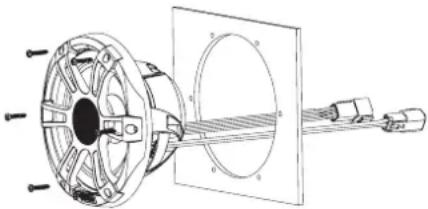
natural_image
Technical diagram of a mechanical assembly with labeled components (no text or symbols present)15 Secure the subwoofer to the mounting surface using the included screws.
NOTE: Do not over tighten the screws, especially if the mounting surface is not flat.
Speaker Wiring
When connecting the subwoofer to your amplifier, observe these considerations.
- The wires on the speaker are terminated with connectors, and you should use the provided harness when connecting the speaker wires to the amplifier.
- Speaker wire is not included with subwoofer. You should use 12 AWG (3.31 mm ^2 ) or larger speaker wire to connect the wiring harness to the amplifier.
You can use these tables to identify the polarity of the wires on the provided harness.
| Lead color Polarity | |
| White Positive (+) | |
| White with a black stripe Negative (-) |
LED Wiring
It is recommended to install a Fusion CRGBW Wireless Remote Control with these speakers to turn the LEDs on and off, change the colors, and create lighting effects. See your Fusion dealer or www.fusionentertainment.com for more information.
You should follow the instructions provided with the remote control to connect the LED wires from the speakers to the remote control receiver module and to connect the receiver module to power.
If you choose not to install the remote control, you can set the static color of the LEDs by connecting the colored LED wires directly to the power source (Connecting the LED Wires, page 2).
Connecting the LED Wires
If you do not install the recommended remote control, you can set the static color of the LEDs by connecting the colored LED wires from the harness to the negative (-) terminal of a 12 Vdc power source. You can splice the negative (-) wire to multiple LED wires to customize the LED color and tone. You must connect the black LED wire from the harness to the positive (+) terminal of the same power source to complete the circuit.
The LED wires on the speaker are terminated with connectors, and you should use the provided harness when connecting the LED wires to the speaker.
You should use 22 AWG (0.33 mm ^4 ) or thicker wire to connect the LED wires from the harness to the battery.
You must connect the positive (+) wire for all of the speaker LEDs through a 3 A fuse near the power-source. You should
also connect the positive (+) power wire to the power source through an isolator switch or circuit breaker to turn the LEDs on and off. You can use the same isolator or circuit breaker controlling the power supply to your stereo, which allows you to turn the LEDs and the stereo on and off at the same time.
1 Connect the black wire on the LED harness to the positive (+) terminal of the power source.
NOTICE
To avoid damage to the speakers or the vessel, you must connect this wire through a 3 A fuse near the power source.
2 Connect the negative (-) wire from the same power source to one or more colored wires on the LED harness according to the preferred LED color.
NOTICE
You must insulate any unused LED wires on the harness to avoid causing a short circuit.
| LED Color LED Harness Wire Color | |
| Red Red | |
| Green Green | |
| Blue Blue | |
| Yellow Red and green | |
| Magenta Red and blue | |
| Cyan Blue and green | |
| Cool white Turquoise | |
| Warm white Yellow | |
NOTE: You can connect the cool white or warm white wire to change the tone of any LED color combination.
3 Connect the harness to the speaker.
Speaker Information
True-Marine™ Products
True-Marine products are subjected to rigorous environmental testing under harsh marine conditions to surpass industry guidelines for marine products.
Any product that bears the True-Marine stamp of assurance has been designed for simplicity of use and combines advanced marine technologies to deliver an industry leading entertainment experience. All True-Marine products are supported by the Fusion 3-year worldwide limited consumer warranty.
Registering Your Subwoofer
Help us better support you by completing our online registration today.
- Go to www.fusionentertainment.com/marine/register.
- Keep the original sales receipt, or a photocopy, in a safe place.
Dimension Drawings
Side View
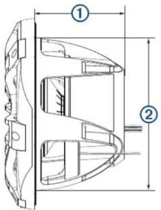
text_image
Technical diagram of a mechanical component with labeled parts ① and ②, showing internal structure and dimension lines.| 1 | 204 mm ( 8^1/_16 in.) |
| 2 | 303 mm ( 11^15/_16 in.) |
Front View
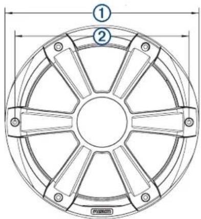
text_image
Technical diagram of a circular mechanical component with labeled parts and dimension lines| 1 | 356 mm (14 in.) |
| 2 | 325 mm ( 12^13/_16 in.) |
Back View
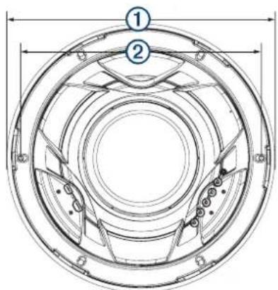
text_image
Technical diagram of a circular mechanical component with numbered parts and dimension lines| 1 | 356 mm (14 in.) |
| 2 | 325 mm ( 12^13/_16 in.) |
Cleaning the Subwoofer
NOTICE
Do not use harsh or solvent-based cleaners on the subwoofer. Using such cleaners may damage the product and void the warranty.
When mounted correctly, this subwoofer is rated IP65 for protection in the harsh marine environment from the front of the subwoofer. The subwoofer is not designed to withstand high pressure water spray, which may occur when you wash down your vessel. Failure to carefully spray-clean the vessel may damage the product and void the warranty.
1 Clean all salt water and salt residue from the grille with a damp cloth soaked in fresh water.
2 Use a mild detergent to remove a heavy buildup of salt or stains.
Specifications
| Max. power 1400 W | |
| RMS power 700 W | |
| Frequency response From 20 Hz to 2 kHz | |
| Sensitivity (1 W/1 m) 86 dB | |
| Impedance 4 ohms | |
| Nominal voice coil diameter 100 mm | |
| Amplifier power-rating recommendation | 200 to 1000 W RMS, playing music |
| Min. mounting depth (clearance) 207 mm (8 ^5/_32 in.) | |
| Mounting diameter (clearance) 306 mm (12 ^3/_64 in.) | |
| Grille height from surface 50 mm (2 in.) | |
| Compass-safe distance 460 cm (181 in.) | |
| LED Supply Voltage (Sports Model Speakers only) | From 10.8 to 16 Vdc |
| LED Load Current at 14.4 Vdc (Sports Model Speakers only) | 300 mA |
| Operating temperature range From 0 to 50°C (from 32 to 122°F) | |
| Storage temperature range From -20 to 70°C (from -4 to 158°F) | |
| Cone material Polypropylene cone with rubber surround | |
| Water and dust rating IEC 60529 IP65 | 1 |
Optimum Enclosure Recommendations
| Sealed enclosure volume when fully filled with absorption material. | ≥ 60 L (2.12 ft.^3) |
| Ported (vented) enclosure volume when lined with absorption material. | 250 L (8.83 ft.) ^3) |
| Port diameter 101.6 mm (4 in.) | |
| Port length 127 mm (5 in.) |
低功率電波輻射電機管理宣告
© 2020 Garmin Ltd. or its subsidiaries
Garmin ^b , the Garmin logo, Fusion ^b , the Fusion logo, and True-Marine ^™ are trademarks of Garmin Ltd. or its subsidiaries, registered in the USA and other countries. These trademarks may not be used without the express permission of Garmin.