SG-S102W - Subwoofer Fusion - Free user manual and instructions
Find the device manual for free SG-S102W Fusion in PDF.

| Product Type | Subwoofer |
| Brand | Fusion |
| Model | SG-S102W |
| Dimensions (H x W x D) | 380 x 320 x 360 mm |
| Weight | 8 kg |
| Power Supply | 100-240V, 50/60Hz |
| Power Output | 100W RMS |
| Speaker Driver | 10 inch (25 cm) |
| Impedance | 8 ohms |
| Frequency Response | 30 Hz - 150 Hz |
| Connectivity | Line input (RCA) |
| Controls | Volume, Crossover, Phase switch |
| Enclosure Type | Bass-reflex (ported) |
| Cabinet Material | MDF |
| Finish | Black vinyl |
| Protection | Short circuit, overheat |
| Cleaning | Wipe with dry cloth |
| Safety | Do not expose to water or moisture |
| Spare Parts | Contact customer support |
| Manual | Available for download in PDF |
Frequently Asked Questions - SG-S102W Fusion
User questions about SG-S102W Fusion
0 question about this device. Answer the ones you know or ask your own.
Ask a new question about this device
Download the instructions for your Subwoofer in PDF format for free! Find your manual SG-S102W - Fusion and take your electronic device back in hand. On this page are published all the documents necessary for the use of your device. SG-S102W by Fusion.
USER MANUAL SG-S102W Fusion
Signature Series Subwoofer Installation Instructions
Important Safety Information
WARNING
See the Important Safety and Product Information guide in the product box for product warnings and other important information.
WARNING
This device must be installed according to these instructions.
Disconnect the vehicle's or vessel's power supply before beginning to install this device.
CAUTION
Continuous exposure to sound pressure levels over 100 dBA may cause permanent hearing loss. The volume is typically too loud if you cannot hear people speaking around you. Limit the amount of time you listen at high volume. If you experience ringing in your ears or muffled speech, stop listening and have your hearing checked.
Always wear safety goggles, ear protection, and a dust mask when drilling, cutting, or sanding.
NOTICE
When drilling or cutting, always check what is on the opposite side of the surface.
It is strongly recommended that you have your audio system installed by a professional installer to ensure optimum performance.
You must read all installation instructions before beginning the installation. If you experience difficulty during the installation, go to www.fusionentertainment.com for product support.
After installing the subwoofer, you should run the subwoofer at low to medium volumes for the first few hours of use. This helps to improve the overall sound by gradually loosening up the moving components of the subwoofer, such as the cone, spider, and surround
Tools Needed
- Electric drill
- Drill bit (size varies based on surface material)
- Phillips screwdriver
- Appropriate saw or utility knife to cut surface material
- 16 AWG (1.31 mm ^2 ) or larger speaker wire
- 4.8 mm and 6.3 mm female speaker spade connectors (recommended)
- 22 AWG (0.33 mm ^2 ) or larger wire for the LEDs (sports models only)
- 4 mm male and female bullet connectors for the LED wires (recommended, sports models only)
- Wire strippers (optional)
- Crimping tool (optional)
• Electrical tape (optional)
• Marine sealant (optional)
NOTE: For customized installations, additional tools and materials may be needed.
Mounting Considerations
NOTICE
When mounting the subwoofer in an area exposed to weather or water, you must mount the subwoofer on a vertical surface. If you mount the subwoofer on a horizontal surface facing up, water can gather in and around the subwoofer, causing damage over time.
If you intend to mount the subwoofer outside the boat, you must mount it in a location well above the waterline, where it is not submerged or damaged by docks, pilings, or other pieces of equipment. When mounted correctly, this subwoofer is rated for protection from the front of the speaker. Water exposure and damage to the rear of the subwoofer voids the warranty. This includes situations when the subwoofer is mounted in a sealed enclosure, especially if it is exposed to wash down. Using an enclosure with a port or vent exposed to the outside environment may allow water to collect and damage the subwoofer.
You must turn off the audio system before making any connections to the source unit, amplifier, or speakers. Failure to do so could result in permanent damage to the audio system.
You should protect all terminals and connections from grounding and from each other. Failure to do so could result in permanent damage to the audio system and void the product warranty.
When selecting a mounting location for the subwoofer, observe these considerations:
- You must select mounting locations that provide sufficient clearance for the mounting depth of the subwoofer as specified in the product specifications.
- You should select a flat mounting surface for the best seal.
- You should select a location where the surface material is thick enough to support the weight of the subwoofer. It's important to note that when in use, the subwoofer exerts a pushing and pulling effect on the surface, so if the material is thin, it can result in excess vibration and negatively affect the sound quality.
- You should protect the speaker wires from sharp objects and always use rubber grommets when wiring through panels.
- To avoid interference with a magnetic compass, you should not mount the subwoofer closer to a compass than the compass-safe distance value listed in the product specifications.
Selecting the correct mounting location optimizes the performance of the subwoofer. FUSION ^® speakers are designed to perform in the widest possible range of mounting locations, but the more you plan the installation, the better the speakers' sound will be. For more information on subwoofer placement and specifications, go to www.fusionentertainment.com.
Mounting the Subwoofer
Before mounting the subwoofer, you must choose a location following the guidelines above.
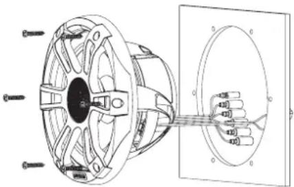
1 Route the speaker wires (and LED wires, if applicable) from the source to the speaker location.
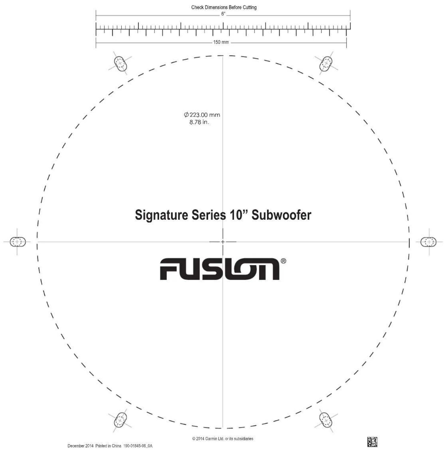
2 Trim the template and make sure it fits in the selected location.
3 Orient the template with the FUSION logo at the bottom of the template.
4 Secure the template to the selected location.
5 Using a jigsaw or rotary tool, cut the mounting surface along the inside of the line on the template.
6 Place the subwoofer in the cutout to test the fit.
7 If necessary, use a file and sandpaper to refine the size of the cutout.
8 After the subwoofer fits correctly in the cutout, ensure the mounting holes on the subwoofer line up with the pilot holes on the template.
9 If the mounting holes do not line up, mark the new hole locations.
10 Using an appropriately sized drill bit for the mounting surface and screw type, drill the holes.
11 Remove the template from the mounting surface.
12 Connect the subwoofer wires while observing polarity (Speaker Wiring, page 2).
13 If necessary, connect the LED wires to the Sports model subwoofer (LED Wiring, page 2).
14 Place the subwoofer in the cutout.
natural_image
Technical line drawing of a mechanical component with mounting holes and internal wiring (no text or symbols)15 Secure the subwoofer to the mounting surface using the included screws.
NOTE: Do not over tighten the screws, especially if the mounting surface is not flat.
For the Classic model subwoofer, attach the grille to the front.
Speaker Wiring
When connecting the subwoofer to your stereo or amplifier, observe these considerations.
- Speaker wire is not included with subwoofer. You should use 16 AWG (1.31 mm ^2 ) or larger speaker wire to connect the subwoofer to the stereo or amplifier.
- The leads on the subwoofer are terminated using male spade connectors. You should use female spade connectors (not included) to connect the speaker wire to the leads for the best connection.
You can use these tables to identify the polarity and spade-connector sizes of the leads on the subwoofer.
| Lead color Polarity Spade connector size | ||
| White Positive (+) 6.3 mm | ||
| White with a black stripe Negative (-) 4.8 mm | ||
LED Wiring
Connecting the LED Wires
You can control the color of the LEDs by connecting the colored LED wires to the negative (-) terminal of a 12 VDC power source. You can splice the negative (-) wire to multiple LED wires to customize the LED color and tone. You must connect the black LED wire to the positive (+) terminal of the same 12 VDC power source to complete the circuit.
NOTE: This feature is available only on the sports model.
NOTE: Instead of connecting the LED wires for one dedicated color, you can install a remote control to turn the LEDs on and off, change the color, and create lighting effects. See your FUSION dealer or www.fusionentertainment.com for more information.
The black wire on the LED cable is terminated with a 4 mm female bullet connector, and the color wires are terminated with 4 mm male bullet connectors. You can connect these to 4 mm bullet connectors on your wires (not included), or remove the bullet connectors to connect to the bare wires instead.
1 Connect the positive (+) wire from a 12 VDC power source to the black wire on the LED cable.
2 Connect the negative (-) wire from the same 12 VDC power source to the colored wire or wires on the LED cable according to the preferred LED color.
| LED Color LED Wire Color | |
| Red Red | |
| Green Green | |
| Blue Blue | |
| Yellow Red and green | |
| Magenta Red and blue | |
| Cyan Blue and green | |
| Cool white Turquoise | |
| Warm white Yellow |
NOTE: You can connect the cool white or warm white wire to change the tone of any LED color combination.
3 If necessary, route the positive and negative wires, and connect them to a 12 VDC power source (Connecting the LED Wires to Power, page 2).
Connecting the LED Wires to Power
NOTE: This feature is available on only the sports model.
You must connect all 12 Vdc wiring to the LEDs to a 3 A fuse at the power-source end of the cable. You should connect the positive (+) power wire to a 12 Vdc power source through an isolator switch or circuit breaker to turn the LEDs on and off. You can use the same isolator or circuit breaker controlling the power supply to your stereo, which allows you to turn the LEDs and the stereo on and off at the same time.
You should use 22 AWG (0.33 mm ^4 ) or thicker wire to connect the LEDs to the battery.
1 Route the positive power (+) and negative ground (-) wires from the LED-wire connections to the battery.
2 Connect the negative wire to the negative (-) battery terminal.
3 Connect the positive wire to the positive (+) terminal through a 3 A fuse and isolator switch or circuit breaker.
Attaching the grille to the Classic Model Subwoofer
NOTE: This feature is available only on the Classic model subwoofer.
1 With the subwoofer mounted, hold the grille with the FUSION logo at the bottom, at the 6 o'clock position.
2 Turn the grille counter-clockwise about 10^ , so the FUSION logo is at the 5 o'clock position.
3 Place the grille on the rim of the subwoofer.
4 Twist the grille clockwise to secure it.
Speaker Information
True-Marine™ Products
True-Marine products are subjected to rigorous environmental testing under harsh marine conditions to surpass industry guidelines for marine products.
Any product that bears the True-Marine stamp of assurance has been designed for simplicity of use and combines advanced marine technologies to deliver an industry leading entertainment experience. All True-Marine products are supported by the FUSION 3-year worldwide limited consumer warranty.
Registering Your Subwoofer
Help us better support you by completing our online registration today.
- Go to www.fusionentertainment.com.
- Keep the original sales receipt, or a photocopy, in a safe place.
Dimension Drawings
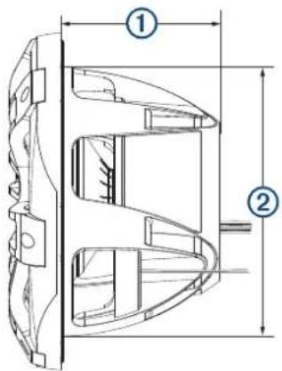
Side View
text_image
Technical diagram of a mechanical component with labeled parts ① and ②, showing internal structure and dimension lines.| 1 | 130 mm ( 5^1/_8 in.) |
| 2 | 220 mm ( 8^21/_32 in.) |
A Sports model subwoofer is shown, but the dimensions are the same for the Classic model.
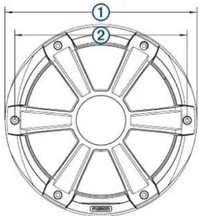
Sports Model Front View
text_image
Technical diagram of a circular mechanical component with labeled parts and dimension lines| 1 | 275 mm ( 10^13y_16 in.) |
| 2 | 247 mm ( 9^3/_4 in.) |
Classic Model Back View
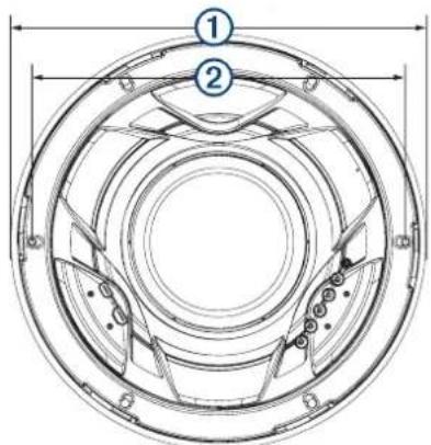
text_image
Technical diagram of a circular mechanical component with numbered parts and dimension lines| 1 | 275 mm ( 10^13y_16 in.) |
| 2 | 247 mm ( 9^3/_4 in.) |
Cleaning the Subwoofer
NOTICE
Do not use harsh or solvent-based cleaners on the subwoofer. Using such cleaners may damage the product and void the warranty.
When mounted correctly, this subwoofer is rated IP65 for protection in the harsh marine environment from the front of the subwoofer. The subwoofer is not designed to withstand high pressure water spray, which may occur when you wash down your vessel. Failure to carefully spray-clean the vessel may damage the product and void the warranty.
1 Clean all salt water and salt residue from the grille with a damp cloth soaked in fresh water.
2 Use a mild detergent to remove a heavy buildup of salt or stains.
Specifications
| Max. power 600 W | |
| RMS power 300 W | |
| Sensitivity (1 W/1 m) 87 dB | |
| Frequency response From 30 Hz to 2 kHz | |
| Min. mounting depth (clearance) 133 mm (5 ^1/_4 in.) | |
| Mounting diameter (clearance) 223 mm (8 ^13/_16 in.) | |
| Impedance 4 ohms | |
| Amplifier power-rating recommendation | 50 to 400 W RMS, playing music |
| Compass-safe distance 520 cm (205 in.) | |
| LED supply voltage (Sports model only) | From 10.8 to 16 Vdc |
| LED load current at 14.4 Vdc (Sports model only) | 300 mA |
| Operating temperature range From 0 to 50°C (from 32 to 122°F) | |
| Storage temperature range From -20 to 70°C (from -4 to 158°F) | |
| Cone material PP cone with Santoprene rubber surround | |
| Water and dust rating IEC 60529 IP65 | |
Optimum Enclosure Recommendations
| Sealed enclosure volume1 | 17.2 L (0.6 ft.3) |
| Ported (vented) enclosure volume2 | 45 L (1.6 ft.)3) |
| Port diameter 104 mm (4 in.) | |
| Port length 265 mm (10 | ^7/_16 in.) |
連絡地址
製造銷售:台灣國際航電股份有限公司
© 2019 Garmin Ltd. or its subsidiaries
Garmin ^7 , the Garmin logo, FUSION ^6 , the Fusion logo, and True-Marine ^™ are trademarks of Garmin Ltd. or its subsidiaries, registered in the USA and other countries. These trademarks may not be used without the express permission of Garmin.
^1 Fully filled with absorption material.
^2 Lined with absorption material.