AM260HXVAHH - Séparateur SAMSUNG - Free user manual and instructions
Find the device manual for free AM260HXVAHH SAMSUNG in PDF.

User questions about AM260HXVAHH SAMSUNG
0 question about this device. Answer the ones you know or ask your own.
Ask a new question about this device
Download the instructions for your Séparateur in PDF format for free! Find your manual AM260HXVAHH - SAMSUNG and take your electronic device back in hand. On this page are published all the documents necessary for the use of your device. AM260HXVAHH by SAMSUNG.
USER MANUAL AM260HXVAHH SAMSUNG
Air Conditioner installation manual
imagine the possibilities
Thank you for purchasing this Samsung product.
Contents
Safety precautions 3
Preparing for installation 8
Selecting installation location 25
Space requirement for installation 27
Accessories 29
Base construction and installation of the outdoor unit 30
Installing the wind/snow prevention duct 35
Refrigerant pipe installation 37
Electrical wiring work 61
Air tightness test and vacuum drying 76
Pipe insulation 78
Charging additional refrigerant 82
Basic segment display 84
Setting outdoor unit option switch and key function 84
Things to check after completing the installation 94
Inspection and test operation 96
Automatic refrigerant amount detection function 100
Safety precautions
Please follow the following safety information for safety of the installer and the user.
* DVM S air conditioner uses R-410A refrigerant.
- When using R-410A, moisture or foreign substances may affect the performance and reliability of the product. Safety precautions must be obeyed when installing the refrigerant pipe.
- The designed maximum pressure of the system is 4.1 MPa and therefore select appropriate material and thickness according to the regulations.
- R-410A is a quasi-azeotrope of two refrigerants and it has to be charged in liquid phase when filling the refrigerant. (If you charge vapor refrigerant, it may change the blend of the refrigerant and cause product malfunction.)
* You must connect the indoor units for R-410A refrigerant. Refer to product catalog to find out the models names for connectable indoor units. (If you connect the indoor units that are not designed for R-410A, it cannot operate normally.)
* After completing the installation and trial operation, explain to the user how to use and maintain the product. Also, hand over this installation manual so that it can be stored by the user.
* Manufacturer is not responsible for the incidents occurred by improper installation. Installer is responsible for any installation related claims from the user occurred by neglecting warnings and cautions stated in this manual. (Installer will be responsible for any service charges that may occur)
* Generally, system air conditioners should not be relocated after installation. But when it has to be relocated for inevitable reasons, please contact Samsung's qualified dealers for system air conditioners.
| WARNING | Hazards or unsafe practices that may result in severe personal injury or death. |
| CAUTION | Hazards or unsafe practices that may result in minor personal injury (to installer/user) or property damage. |
Safety precautions
SEVERE WARNING SIGNS
Consult qualified installer or dealer for installation.
▶ When installation is done by unqualified person, problems such as water leakage, electric shock or fire may occur.
Installation work must be done properly according to this installation manual.
▶ When installation is not done properly, it may cause water leakage, electric shock or fire.
When installing the unit in a small room, take measure to keep the refrigerant concentration from exceeding allowable safety limits in case of refrigerant leakage. Consult the dealer for precautionary measure before the installation.
▶ When refrigerant leaks and exceed dangerous concentration level, it may cause suffocation accidents.
If any gas or impurities, except R-410A refrigerant, come into the refrigerant pipe, serious problem may occur and it may cause injury.
Use the supplied accessories, specified components and tools for the installation.
▶ Do not use the pipe and the installation product used for the R-22 refrigerant.
▶ Failure to use the specified components can cause product fall down, water leakage, electrical shock, and fire. (The pipe and flare components used for R-22 refrigerant must not be used)
Install the outdoor unit on a hard and even place that can support its weight.
▶ If the place cannot support its weight, the outdoor unit may fall down and it may cause injury.
Check the following before installation and service work.
▶ Before welding, remove dangerous and inflammable things that may cause an explosion and fire around the work.
Before welding, remove the refrigerant from inside the pipe or the product.
- If you perform welding while refrigerant is in the pipe, it may increase the pressure of the refrigerant and cause the pipe to burst. If the pipe bursts or explodes, it may cause severe injury to the installer.
When welding, use the nitrogen gas to eliminate oxidation inside the pipe.
Do not modify the product on your own.
▶ Potential risk of electric shock, fire, product failure or injury.
Fix the outdoor unit securely on foundation to resist strong wind or earthquake.
▶ If the outdoor unit is not properly fixed, it turns over and accidents may occur.
Electric work must be done by qualified persons, complying the national wiring regulations and installed according to the instruction stated in the installation manual with leased circuit.
▶ Capacity shortage on the leased circuit and improper installation may cause electric shock or fire.
Make sure to perform grounding work.
▶ Do not connect the ground wire to a gas pipe, water pipe, lightning rod or telephone grounding. Improper grounding could cause electric shock.
Wiring must be connected with the designated wires and it must be fixed securely so that it does not apply any external force to the connection part of the terminals.
▶ If connection for fixation is not properly done, it may cause heat generation or fire.
Neatly arrange the wires in the electrical parts to make sure that electrical cover is closed securely without any gaps.
▶ If the cover is not properly closed, heat may generate on the electrical terminal and cause electric shock or fire.
Exclusive circuit breaker (MCCB, ELB) must be installed to the power supply.
▶ When overcurrent or current leakage occurs with no circuit breaker installed, power will not be cut-off and it may cause electric shock or fire.
▶ Do not use damaged parts. It may cause fire or electric shock.
You must cut-off the power before you work on, or adjust any power supply part for product installation, maintenance, repair or any other services.
▶ There is risk of electric shock.
Even when the power is off, it is dangerous when you come in contact with inverter PCB, fan PCB since high pressure DC voltage is charged to those parts.
When replacing/repairing the PCB, cut-off the power and wait until the DC voltage is discharged before replacing/repairing them. (Wait for more than 15 minutes to allow it to discharge naturally.)
If the refrigerant gas leaks during the installation, you should ventilate the room.
▶ When the refrigerant gas gets in contact with flammable substance, it may generate toxic gas.
Gas leakage must be checked after installation is completed.
▶ When the refrigerant gas gets in contact with flammable substance, it may generate toxic gas.
You can get a frostbite if you get in contact with the leaked refrigerant gas.
Supply power to the product during winter time since the product will operate in protection mode itself when the temperature decrease below 0 ^(32 ^) .
▶ If you cut-off the power, compressor protection mode cannot be operated and may cause damage to the product.
Safety precautions
CAUTION SIGNS
Do not install the drain pipe directly to the bottom part of the outdoor unit and built a proper drainage so that water drains out smoothly. If not, pipe may freeze or bursts during winter time and cause damage to the product or water leakage.
▶ When the draining work is not done properly, water leak may occur and cause property damage.
Install the power cable and communication cable of the indoor and outdoor unit at least 1.5 m (4.92 ft) away from the electric appliances and install it at least 2 m(6.56 ft) away from the lightning conductor.
▶ Noise may be generated from the electronic devices, depending on the status of the electric wave.
Install the outdoor unit within the angle stated in the table, according to the height of the building.
▶ Do not leave the refrigerant container under the hot sunlight. (There is risk of explosion.)
▶ You must use the appropriate pipes according to the standard since the pressure of the refrigerant is very high.
▶ Make sure that the pipes does not get any weaker by welding it too much.
▶ Make sure to install the product away from children's reach. (Sharp parts of the heat exchanger is may cause personal injury and when parts of the product gets damage, it may decrease product's performance.)
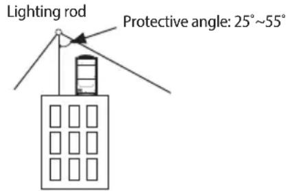
| Height of the building Protection control | |
| 20 m(65.62 ft) or less 55° | |
| 40 m(131.23 ft) or less 35° | |
| 60 m(196.85 ft) or less 25° | |
Install the indoor unit away from lighting apparatus that uses ballast stabilizer.
▶ If you use the wireless remote control, it may not operate normally due to ballast stabilizer.
Do not install the product in following places.
Place where outdoor unit's noise and warm air may disturb neighbors. (It may cause property loss.)
▶ Do not leave any obstacles around the inlet and outlet of the product. (It may cause damage or accidents.)
The place where there is mineral oil or arsenic acid.
- Those parts may get damaged due to burned resin and cause water leakage or product may fall.
- The efficiency of the heat exchanger may reduce or product may break.
The place where corrosive gas such as sulfurous acid gas generates from the vent pipe or air outlet.
- The copper pipe or connection pipe may corrode and refrigerant may leak.
The place where there is a machine that generates electromagnetic waves.
- The air conditioner may not operate normally due to problems in control system.
The place where there is a danger of combustible gas leakage or place where thinner or gasoline is handled.
- (There is risk of fire or explosion.)
▶ The place with carbon fiber or flammable dust.
The place near seashore or hot spring where there is risk of outdoor unit corrosion.
Changes in DVM S (inverter) compare to conventional models that has to noted when installing
For optimal distribution of the refrigerant, you must use Y-joint as branch joint for connecting outdoor units. (To not use T-joint)
▶ You cannot operate normally if you do not complete the trial operation through outdoor unit key mode. You must use KEY MODE to run trial operation.
▶ DVM S air conditioner uses R-410A refrigerant.
▶ Check the compatibility of other products such as indoor unit, EEV kits etc. which will be connected to DVM S.
▶ Make sure to note that outdoor unit combination is different from DVM PLUS III and IV.
The length of maximum piping, level difference, the quantity of connectable indoor units, the installation at the outdoor joints and the outdoor unit combinations are different from the conventional models.
If the pipe length is over 2 m(6.56 ft) between outdoor units, make traps to prevent oil stagnation. Oil stagnation may occur when outdoor unit at the end of module stops while other outdoor units are still in operation.
Preparing for installation
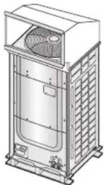
Outdoor unit classification
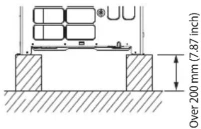
| Classification Small type Large type | ||
| Appearance | 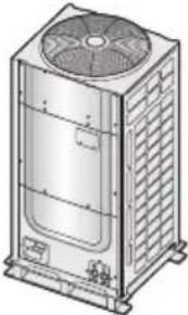 | 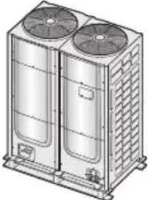 |
| Models | AM080/100/120*XV*H* | AM140/160/180/200/220/240/260*XV*H* |

Packaging material disposition
Safely store or dispose the packaging materials.
- Sharp metals such as nails or wooden material packaging that may break into pieces become a cause for personal injury.
- Make sure to store or dispose the vinyl type packaging material to keep it out of reach of children. Children may put them over their face, which is very dangerous since it may lead them to suffocation.
Outdoor unit combination
▶ Make sure to use an indoor unit that is compatible with DVM S.
Indoor units can be connected within the range indicated in following table.
If the total capacity of the connected indoor units exceeds the indicated maximum capacity, cooling and heating capacity of the indoor unit may decrease.
▶ Total capacity of the connected indoor units can be allowed from 50% to 130% of the total outdoor unit capacity. 0.5 × (Outdoor unit capacity) ≤ Total capacity of the connected indoor units ≤ 1.3 × (Outdoor unit capacity)
* You can connect maximum 64 indoor units to the outdoor unit. Maximum quantity of connectable indoor unit is set to 64 since outdoor unit only support up to 64 communication address. Indoor unit address can be assigned from 0\~63. If the indoor unit address was assigned from 64\~79, E201 error will occur.
* Maximum 32 Wall-mount type indoor units with EEV (AM****NQDCH*) can be connected.

• Installation combination must be complied when composing outdoor unit combination.
Standard type
| Model name for combination AM080 | FXVAHH AM100FXVAHH AM120FXVAHH AM140FXVAHH AM160FXVAHH | |||||
| Number of individual outdoor units 1 1 1 | 1 1 | |||||
| Combined outdoor unit | AM080FXVAHH 1 | |||||
| AM100FXVAHH 1 | ||||||
| AM120FXVAHH 1 | ||||||
| AM140FXVAHH 1 | ||||||
| AM160FXVAHH 1 | ||||||
| AM180FXVAHH | ||||||
| AM200FXVAHH | ||||||
| AM220FXVAHH | ||||||
| AM240HXVAHH | ||||||
| AM260HXVAHH | ||||||
| Rated capacity | Cooling (kW) 224 28.0 33.6 40.0 45.0 | |||||
| Cooling (Btu/h) 76 400 95 500 114 600 136 500 153 500 | ||||||
| Heating (kW) | 25.2 31.5 37.8 45.0 50.0 | |||||
| Heating (Btu/h) | 86 000 107 500 129 000 153 500 170 600 | |||||
| Total capacity of the connected indoor units (Cooling) | Minimum (kW) | 11.2 14.0 16.8 20.0 22.5 | ||||
| Minimum (Btu/h) | 38 200 47 800 57 300 68 200 76 800 | |||||
| Maximum (kW) 29.1 36.4 43.7 52.0 58.5 | ||||||
| Maximum (Btu/h) | 99 400 124 200 149 000 177 400 199 600 | |||||
| Maximum number of connectable indoor units | 14 | 18 | 21 | 26 | 29 | |
| Model name for combination | AM180FXVAHH | AM200FXVAHH | AM220FXVAHH | AM240HXVAHH | AM260HXVAHH | |
| Number of individual outdoor units 1 1 1 | 1 1 | |||||
| Combined outdoor unit | AM080FXVAHH | |||||
| AM100FXVAHH | ||||||
| AM120FXVAHH | ||||||
| AM140FXVAHH | ||||||
| AM160FXVAHH | ||||||
| AM180FXVAHH 1 | ||||||
| AM200FXVAHH 1 | ||||||
| AM220FXVAHH 1 | ||||||
| AM240HXVAHH | 1 | |||||
| AM260HXVAHH | 1 | |||||
| Rated capacity | Cooling (kW) 50.4 56.0 61.6 67.2 72.8 | |||||
| Cooling (Btu/h) | 172 000 191 100 210 200 229 300 248 400 | |||||
| Heating (kW) | 56.7 63.0 69.3 75.6 81.9 | |||||
| Heating (Btu/h) | 193 500 215 000 236 500 258 000 279 500 | |||||
| Total capacity of the connected indoor units (Cooling) | Minimum (kW) | 25.2 28.0 30.8 33.6 36.4 | ||||
| Minimum (Btu/h) | 86 000 95 500 105 100 114 600 124 200 | |||||
| Maximum (kW) 65.5 72.8 80.1 87.4 94.6 | ||||||
| Maximum (Btu/h) | 223 600 248 400 273 200 298 100 322 900 | |||||
| Maximum number of connectable indoor units | 32 | 36 | 40 | 43 | 47 | |
Preparing for installation
| Model name for combination AM280 | HXVAHH1 AM300H | XVAHH1 AM320HX | VAHH1 AM340HXV | VAHH1 AM360HXVA | HH1 | |
| Number of individual outdoor units 2 2 2 | 2 2 | |||||
| Combined outdoor unit | AM080FXVAHH | |||||
| AM100FXVAHH | ||||||
| AM120FXVAHH 1 | 1 1 1 | |||||
| AM140FXVAHH 1 | ||||||
| AM160FXVAHH 1 | ||||||
| AM180FXVAHH 1 | ||||||
| AM200FXVAHH 1 | ||||||
| AM220FXVAHH 1 | 1 | |||||
| AM240HXVAHH | ||||||
| AM260HXVAHH | ||||||
| Rated capacity | Cooling (kW) 78 | 6 84.0 89.6 95.2 101 | 6 | |||
| Cooling (Btu/h) 26 | 8 200 286 600 305 7 | 00 324 800 346 700 | ||||
| Heating (kW) | 87.8 | 94.5 | 100.8 | 107.1 | 114.3 | |
| Heating (Btu/h) | 299 600 322 4 | 00 343 900 365 400 3 | 90 000 | |||
| Total capacity of the connected indoor units (Cooling) | Minimum (kW) | 39.3 42.0 44.3 | 47.6 50.8 | |||
| Minimum (Btu/h) | 134 100 143 3 | 00 152 900 162 400 1 | 73 300 | |||
| Maximum (kW) | 102.2 | 109.2 | 116.5 | 123.8 | 132.1 | |
| Maximum (Btu/h) | 348 700 372 6 | 00 397 400 422 300 4 | 450 700 | |||
| Maximum number of connectable indoor units | 51 | 54 | 58 | 61 | 64 | |
| Model name for combination AM380 | HXVAHH1 AM400H | XVAHH1 AM420HX | VAHH1 AM440HXV | VAHH1 AM460HXVAHH1 | |
| Number of individual outdoor units 2 2 2 | 2 3 | ||||
| Combined outdoor unit | AM080FXVAHH | ||||
| AM100FXVAHH | |||||
| AM120FXVAHH 2 | |||||
| AM140FXVAHH 1 | |||||
| AM160FXVAHH 1 | |||||
| AM180FXVAHH | |||||
| AM200FXVAHH 1 | |||||
| AM220FXVAHH 1 | 1 2 1 | ||||
| AM240HXVAHH | |||||
| AM260HXVAHH | 1 | ||||
| Rated capacity | Cooling (kW) | 106.6 | 112.8 | 117.6 | 123.2 |
| Cooling (Btu/h) 363 | 700 384 900 401 300 | 420 400 439 500 | |||
| Heating (kW) | 119.3 | 126.9 | 132.3 | 138.6 | |
| Heating (Btu/h) | 407 100 433 000 | 451 400 472 900 494 400 | |||
| Total capacity of the connected indoor units (Cooling) | Minimum (kW) | 53.3 56.4 58.3 | 61.6 64.4 | ||
| Minimum (Btu/h) | 181 900 192 400 | 200 600 210 200 219 700 | |||
| Maximum (kW) | 138.6 | 146.6 | 152.9 | 160.2 | |
| Maximum (Btu/h) | 472 900 500 400 | 521 600 546 500 571 300 | |||
| Maximum number of connectable indoor units | 64 | 64 | 64 | 64 | |
| Model name for combination AM480 | HXVAHH1 AM500H | XVAHH1 AM520HX | VAHH1 AM540HXV | AHH1 AM560HXVA | HH1 | |
| Number of individual outdoor units 3 3 3 | 3 3 | |||||
| Combined outdoor unit | AM080FXVAHH | |||||
| AM100FXVAHH | ||||||
| AM120FXVAHH 1 | 1 1 1 1 | |||||
| AM140FXVAHH 1 | ||||||
| AM160FXVAHH 1 | ||||||
| AM180FXVAHH 1 | ||||||
| AM200FXVAHH 1 | ||||||
| AM220FXVAHH 1 | 1 1 1 2 | |||||
| AM240HXVAHH | ||||||
| AM260HXVAHH | ||||||
| Rated capacity | Cooling (kW) 135.2 140.2 145.6 151.2 156.8 | |||||
| Cooling (Btu/h) 461 300 478 400 496 800 515 900 535 000 | ||||||
| Heating (kW) 152.1 157.1 163.8 170.1 176.4 | ||||||
| Heating (Btu/h) 519 000 536 000 558 900 580 400 601 900 | ||||||
| Total capacity of the connected indoor units (Cooling) | Minimum (kW) | 67.6 | 70.1 | 72.8 | 75.6 | 78.4 |
| Minimum (Btu/h) | 230 700 239 200 248 400 258 000 267 500 | |||||
| Maximum (kW) | 175.8 182.3 189.3 196.6 203.8 | |||||
| Maximum (Btu/h) | 599 700 621 900 645 800 670 700 695 500 | |||||
| Maximum number of connectable indoor units | 64 | 64 | 64 | 64 | 64 | |
| Model name for combination | AM580HXVAHH1 | AM600HXVAHH1 | AM620HXVAHH1 | AM640HXVAHH1 | AM660HXVAHH1 | AM680HXVAHH1 | |
| Number of individual outdoor units | 3 | 3 | 3 | 3 | 3 | 4 | |
| Combined outdoor unit | AM080FXVAHH | ||||||
| AM100FXVAHH | |||||||
| AM120FXVAHH | 2 | ||||||
| AM140FXVAHH | 1 | ||||||
| AM160FXVAHH | 1 | ||||||
| AM180FXVAHH | 1 | ||||||
| AM200FXVAHH | 1 | ||||||
| AM220FXVAHH | 2 | 2 | 2 | 2 | 3 | 2 | |
| AM240HXVAHH | |||||||
| AM260HXVAHH | |||||||
| Rated capacity | Cooling (kW) | 163.2 | 168.2 | 173.6 | 179.2 | 184.8 | 190.4 |
| Cooling (Btu/h) | 556 900 | 573 900 | 592 300 | 611 500 | 630 600 | 649 700 | |
| Heating (kW) | 183.6 | 188.6 | 195.3 | 201.6 | 207.9 | 214.2 | |
| Heating (Btu/h) | 626 500 | 643 500 | 666 400 | 687 900 | 709 400 | 730 900 | |
| Total capacity of the connected indoor units (Cooling) | Minimum (kW) | 81.6 | 84.1 | 86.8 | 89.6 | 92.4 | 95.2 |
| Minimum (Btu/h) | 278 400 | 287 000 | 296 200 | 305 700 | 315 300 | 324 800 | |
| Maximum (kW) | 212.2 | 218.7 | 225.7 | 233.0 | 240.2 | 247.5 | |
| Maximum (Btu/h) | 723 900 | 746 100 | 770 100 | 794 900 | 819 700 | 844 600 | |
| Maximum number of connectable indoor units | 64 64 | 64 64 | 64 64 | ||||
Preparing for installation
| Model name for combination | AM700HXVAHH1 | AM720HXVAHH1 | AM740HXVAHH1 | AM760HXVAHH1 | AM780HXVAHH1 | AM800HXVAHH1 | |
| Number of individual outdoor units 4 4 4 | 4 4 4 | ||||||
| Combined outdoor unit | AM080FXVAHH | ||||||
| AM100FXVAHH | |||||||
| AM120FXVAHH 1 | 1 1 1 1 | ||||||
| AM140FXVAHH 1 | 1 | ||||||
| AM160FXVAHH 1 | |||||||
| AM180FXVAHH 1 | |||||||
| AM200FXVAHH 1 | |||||||
| AM220FXVAHH 2 | 2 2 2 3 3 | ||||||
| AM240HXVAHH | |||||||
| AM260HXVAHH | |||||||
| Rated capacity | Cooling (kW) 196.8 | 201.8 | 207.2 | 212.8 | 218.4 | 224.8 | |
| Cooling (Btu/h) 671 | 500 | 688 | 600 | 707 | 000 | 726 | |
| Heating (kW) 221 | 4 | 226.4 | 233.1 | 239.4 | 245.7 | 252.9 | |
| Heating (Btu/h) 755 | 400 | 772 | 500 | 795 | 400 | 816 | |
| Total capacity of the connected indoor units (Cooling) | Minimum (kW) 98.4 | 100.9 | 103.6 | 106.4 | 109.2 | 112.4 | |
| Minimum (Btu/h) | 335 | 800 | 344 | 300 | 353 | 500 | |
| Maximum (kW) | 255.8 | 262.3 | 269.4 | 276.6 | 283.9 | 292.2 | |
| Maximum (Btu/h) | 873 | 000 | 895 | 100 | 919 | 100 | |
| Maximum number of connectable indoor units | 64 | 64 | 64 | 64 | 64 | ||
Compact type
| Model name for combination AM360HXV | AHH2 AM380HXVAHH | 2 AM460HXVAHH2 | AM480HXVAHH2 | ||
| Number of individual outdoor units 2 2 2 2 | |||||
| Combined outdoor unit | AM120FXVAHH 1 | ||||
| AM200FXVAHH 1 | |||||
| AM220FXVAHH 1 | |||||
| AM240HXVAHH 1 | |||||
| AM260HXVAHH 1 1 | |||||
| Rated capacity | Cooling (kW) 100.8 | 106.4 | 128.8 | 134.4 | |
| Cooling (Btu/h) 343 | 900 | 363 | 100 | 439 | |
| Heating (kW) 113 | 4 | 119.7 | 144.9 | 151.2 | |
| Heating (Btu/h) 386 | 900 | 408 | 400 | 494 | |
| Total capacity of the connected indoor units (Cooling) | Minimum (kW) | 50.4 | 53.2 | 64.4 | 67.2 |
| Minimum (Btu/h) | 172 | 000 | 181 | 500 | |
| Maximum (kW) | 131.0 | 138.3 | 167.4 | 174.7 | |
| Maximum (Btu/h) | 447 | 100 | 472 | 000 | |
| Maximum number of connectable indoor units | 64 | 64 | 64 | 64 | |
| Model name for combination AM500HXV | AHH2 AM520HXVAHH | 2 AM580HXVAHH2 | AM600HXVAHH2 | ||
| Number of individual outdoor units 2 2 3 3 | |||||
| Combined outdoor unit | AM120FXVAHH 1 1 | ||||
| AM200FXVAHH 1 | |||||
| AM220FXVAHH 1 | |||||
| AM240HXVAHH 1 | |||||
| AM260HXVAHH 1 2 1 1 | |||||
| Rated capacity | Cooling (kW) 140.0 145.6 | 162.4 | 168.0 | ||
| Cooling (Btu/h) 477 700 496 800 | 554 100 | 573 200 | |||
| Heating (kW) 157 5 163.8 | 182.7 | 189.0 | |||
| Heating (Btu/h) 537 400 558 900 | 623 400 | 644 900 | |||
| Total capacity of the connected indoor units (Cooling) | Minimum (kW) | 70.0 | 72.8 | 81.2 | 84.0 |
| Minimum (Btu/h) | 238 800 248 400 | 277 100 | 286 600 | ||
| Maximum (kW) | 182.0 189.3 21 | 1.1 218.4 | |||
| Maximum (Btu/h) | 621 000 645 800 | 720 400 745 200 | |||
| Maximum number of connectable indoor units | 64 | 64 | 64 | 64 | |
Preparing for installation
| Model name for combination AM620HXV | AHH2 AM640HXVAHH | 2 AM680HXVAHH2 | AM700HXVAHH2 | ||
| Number of individual outdoor units 3 3 3 3 | |||||
| Combined outdoor unit | AM120FXVAHH | 1 | 1 | ||
| AM200FXVAHH | |||||
| AM220FXVAHH 2 2 | |||||
| AM240HXVAHH 1 | 1 | ||||
| AM260HXVAHH 1 2 1 | |||||
| Rated capacity | Cooling (kW) | 173.6 179.2 190.4 196.0 | |||
| Cooling (Btu/h) | 592 300 611 500 649 700 668 800 | ||||
| Heating (kW) | 195.3 201.6 214.2 220.5 | ||||
| Heating (Btu/h) | 666 400 687 900 730 900 752 400 | ||||
| Total capacity of the connected indoor units (Cooling) | Minimum (kW) | 86.8 89.6 95.2 98.0 | |||
| Minimum (Btu/h) | 296 200 305 700 324 800 334 400 | ||||
| Maximum (kW) | 225.7 233.0 247.5 254.8 | ||||
| Maximum (Btu/h) | 770 100 794 900 844 600 869 400 | ||||
| Maximum number of connectable indoor units 64 | 64 64 64 | ||||
| Model name for combination AM720HXVAHH2 AM740HXVAHH2 AM760HXVAHH2 AM780HXVAHH2 | |||||
| Number of individual outdoor units 3 3 3 3 | |||||
| Combined outdoor unit | AM120FXVAHH | ||||
| AM200FXVAHH | |||||
| AM220FXVAHH 1 1 | |||||
| AM240HXVAHH 1 | 1 | ||||
| AM260HXVAHH 1 2 2 3 | |||||
| Rated capacity | Cooling (kW) | 201.6 207.2 212.8 218.4 | |||
| Cooling (Btu/h) | 687 900 707 000 726 100 745 200 | ||||
| Heating (kW) | 226.8 233.1 239.4 245.7 | ||||
| Heating (Btu/h) | 773 900 795 400 816 900 838 400 | ||||
| Total capacity of the connected indoor units (Cooling) | Minimum (kW) | 100.8 103.6 106.4 109.2 | |||
| Minimum (Btu/h) | 343 900 353 500 363 100 372 600 | ||||
| Maximum (kW) | 262.1 269.4 276.6 283.9 | ||||
| Maximum (Btu/h) | 894 300 919 100 943 900 968 800 | ||||
| Maximum number of connectable indoor units 64 | 64 64 64 | ||||
High Efficiency type (Heat pump)
| Model name for combination AM080JXVGHH AM100JXVGHH AM120JXVGHH AM140FXVAHH AM160JXVGHH | ||||||
| Number of individual outdoor units 1 1 1 1 1 | ||||||
| Combined outdoor unit | AM080JXVGHH | 1 | ||||
| AM100JXVGHH 1 | ||||||
| AM120JXVGHH | 1 | |||||
| AM140FXVAHH | 1 | |||||
| AM160JXVGHH | 1 | |||||
| AM180JXVGHH | ||||||
| AM200JXVGHH | ||||||
| Rated capacity | Cooling (kW) | 22.4 28.0 | 33.6 40.0 45.0 | |||
| Cooling (Btu/h) | 76 400 95 500 114 600 136 | 500 153 500 | ||||
| Heating (kW) | 25.2 31.5 | 37.8 45.0 50.0 | ||||
| Heating (Btu/h) | 86 000 107 | 500 129 000 153 | 500 170 600 | |||
| Total capacity of the connected indoor units (Cooling) | Minimum (kW) | 11.2 14.0 | 16.8 20.0 22.5 | |||
| Minimum (Btu/h) | 38 200 47 800 57 300 68 200 | 76 800 | ||||
| Maximum (kW) | 29.1 36.4 | 43.7 52.0 58.5 | ||||
| Maximum (Btu/h) | 99 400 124 | 200 149 000 177 | 400 199 600 | |||
| Maximum number of connectable indoor units | 14 18 21 | 26 29 | ||||
| Model name for combination AM180JXVGHH AM200JXVGHH AM220JXVGHH AM240JXVGHH AM260JXVGHH | ||||||
| Number of individual outdoor units 1 1 2 2 2 | ||||||
| Combined outdoor unit | AM080JXVGHH | |||||
| AM100JXVGHH 1 | ||||||
| AM120JXVGHH | 1 | 2 | 1 | |||
| AM140FXVAHH | 1 | |||||
| AM160JXVGHH | ||||||
| AM180JXVGHH | 1 | |||||
| AM200JXVGHH 1 | ||||||
| Rated capacity | Cooling (kW) | 50.4 56.0 | 61.6 67.2 73.6 | |||
| Cooling (Btu/h) | 172 000 191 | 100 210 200 229 | 300 251 100 | |||
| Heating (kW) | 56.7 63.0 | 69.3 75.6 82.8 | ||||
| Heating (Btu/h) | 193 500 215 | 000 236 500 258 | 000 282 500 | |||
| Total capacity of the connected indoor units (Cooling) | Minimum (kW) | 25.2 28.0 | 30.8 33.6 36.8 | |||
| Minimum (Btu/h) | 86 000 95 500 | 105 100 114 | 600 125 600 | |||
| Maximum (kW) | 65.5 72.8 | 80.1 87.4 95.7 | ||||
| Maximum (Btu/h) | 223 600 248 | 400 273 200 298 | 100 326 500 | |||
| Maximum number of connectable indoor units | 32 36 40 | 43 47 | ||||
Preparing for installation
| Model name for combination AM280JXVGHH AM300JXVGHH AM320JXVGHH AM340JXVGHH AM360JXVGHH | ||||||
| Number of individual outdoor units 2 2 2 2 2 | ||||||
| Combined outdoor unit | AM080JXVGHH | |||||
| AM100JXVGHH | ||||||
| AM120JXVGHH | 1 1 1 | |||||
| AM140FXVAHH | 1 | |||||
| AM160JXVGHH | 1 | 1 | ||||
| AM180JXVGHH | 1 | |||||
| AM200JXVGHH 1 1 1 | ||||||
| Rated capacity | Cooling (kW) | 78.6 84.0 | 89.6 96.0 101 | 0 | ||
| Cooling (Btu/h) | 268 200 286 | 600 305 700 32 | 7 600 344 600 | |||
| Heating (kW) | 87.8 94.5 | 100.8 108.0 1 | 13.0 | |||
| Heating (Btu/h) | 299 600 322 | 400 343 900 36 | 8 500 385 600 | |||
| Total capacity of the connected indoor units (Cooling) | Minimum (kW) | 39.3 42.0 | 44.8 48.0 50.5 | |||
| Minimum (Btu/h) | 134 100 143 | 300 152 900 16 | 3 800 172 300 | |||
| Maximum (kW) | 102.2 109 | 2 116.5 124.8 | 131.3 | |||
| Maximum (Btu/h) | 348 700 372 | 600 397 400 42 | 5 800 448 000 | |||
| Maximum number of connectable indoor units | 51 54 58 | 61 64 | ||||
| Model name for combination AM380JXVGHH AM400JXVGHH AM420JXVGHH AM440JXVGHH AM460JXVGHH | ||||||
| Number of individual outdoor units 2 2 3 3 3 | ||||||
| Combined outdoor unit | AM080JXVGHH | |||||
| AM100JXVGHH | 1 | |||||
| AM120JXVGHH | 1 2 1 | |||||
| AM140FXVAHH | 1 | |||||
| AM160JXVGHH | ||||||
| AM180JXVGHH | 1 | |||||
| AM200JXVGHH 1 2 1 1 1 | ||||||
| Rated capacity | Cooling (kW) | 106.4 112 | 0 117.6 123.2 | 129.6 | ||
| Cooling (Btu/h) | 363 100 382 | 200 401 300 42 | 0 400 442 200 | |||
| Heating (kW) | 119.7 126 | 0 132.3 138.6 | 145.8 | |||
| Heating (Btu/h) | 408 400 429 | 900 451 400 47 | 2 900 497 500 | |||
| Total capacity of the connected indoor units (Cooling) | Minimum (kW) | 53.2 56.0 | 58.8 61.6 64.8 | |||
| Minimum (Btu/h) | 181 500 191 | 100 200 600 21 | 0 200 221 100 | |||
| Maximum (kW) | 138.3 145 | 6 152.9 160.2 | 168.5 | |||
| Maximum (Btu/h) | 472 000 496 | 800 521 600 54 | 6 500 574 900 | |||
| Maximum number of connectable indoor units | 64 64 64 | 64 64 | ||||
| Model name for combination AM480JXVGHH AM500JXVGHH AM520JXVGHH AM540JXVGHH AM560JXVGHH | ||||||
| Number of individual outdoor units 3 3 3 3 3 | ||||||
| Combined outdoor unit | AM080JXVGHH | |||||
| AM100JXVGHH | ||||||
| AM120JXVGHH | 1 1 1 | |||||
| AM140FXVAHH | 1 | |||||
| AM160JXVGHH | 1 | 1 | ||||
| AM180JXVGHH | 1 | |||||
| AM200JXVGHH 1 | 1 2 2 2 | |||||
| Rated capacity | Cooling (kW) | 134.6 140 | 0 145.6 152.0 | 157.0 | ||
| Cooling (Btu/h) | 459 300 477 | 700 496 800 51 | 8 600 535 700 | |||
| Heating (kW) | 150.8 157 | 5 163.8 171.0 | 176.0 | |||
| Heating (Btu/h) | 514 600 537 | 400 558 900 58 | 3 500 600 500 | |||
| Total capacity of the connected indoor units (Cooling) | Minimum (kW) | 67.3 70.0 | 72.8 76.0 78.5 | |||
| Minimum (Btu/h) | 229 600 238 | 800 248 400 25 | 9 300 267 900 | |||
| Maximum (kW) | 175.0 182 | 0 189.3 197.6 | 204.1 | |||
| Maximum (Btu/h) | 597 100 621 | 000 645 800 67 | 4 200 696 400 | |||
| Maximum number of connectable indoor units | 64 64 64 | 64 64 | ||||
| Model name for combination AM580JXVGHH AM600JXVGHH AM620JXVGHH AM640JXVGHH AM660JXVGHH | ||||||
| Number of individual outdoor units 3 3 4 4 4 | ||||||
| Combined outdoor unit | AM080JXVGHH | |||||
| AM100JXVGHH | 1 | |||||
| AM120JXVGHH | 1 2 1 | |||||
| AM140FXVAHH | 1 | |||||
| AM160JXVGHH | ||||||
| AM180JXVGHH | 1 | |||||
| AM200JXVGHH 2 3 2 2 2 | ||||||
| Rated capacity | Cooling (kW) | 162.4 168 | 0 173.6 179.2 | 185.6 | ||
| Cooling (Btu/h) | 554 100 573 | 200 592 300 61 | 1 500 633 300 | |||
| Heating (kW) | 182.7 189 | 0 195.3 201.6 | 208.8 | |||
| Heating (Btu/h) | 623 400 644 | 900 666 400 68 | 7 900 712 500 | |||
| Total capacity of the connected indoor units (Cooling) | Minimum (kW) | 81.2 84.0 | 86.8 89.6 92.8 | |||
| Minimum (Btu/h) | 277 100 286 | 600 296 200 30 | 5 700 316 600 | |||
| Maximum (kW) | 211.1 218 | 4 225.7 233.0 | 241.3 | |||
| Maximum (Btu/h) | 720 400 745 | 200 770 100 79 | 4 900 823 300 | |||
| Maximum number of connectable indoor units | 64 64 64 | 64 64 | ||||
Preparing for installation
| Model name for combination AM680JXVGHH AM700JXVGHH AM720JXVGHH AM740JXVGHH AM760JXVGHH | ||||||
| Number of individual outdoor units 4 4 4 4 4 | ||||||
| Combined outdoor unit | AM080JXVGHH | |||||
| AM100JXVGHH | ||||||
| AM120JXVGHH | 1 1 1 | |||||
| AM140FXVAHH | 1 | |||||
| AM160JXVGHH | 1 | 1 | ||||
| AM180JXVGHH | 1 | |||||
| AM200JXVGHH 2 2 3 3 3 | ||||||
| Rated capacity | Cooling (kW) | 190.6 196 | 0 201.6 208.0 | 213.0 | ||
| Cooling (Btu/h) | 650 400 668 | 800 687 900 70 | 9 700 726 800 | |||
| Heating (kW) | 213.8 220 | 5 226.8 234.0 | 239.0 | |||
| Heating (Btu/h) | 729 500 752 | 400 773 900 79 | 8 400 815 500 | |||
| Total capacity of the connected indoor units (Cooling) | Minimum (kW) | 95.3 98.0 | 100.8 104.0 10 | 06.5 | ||
| Minimum (Btu/h) | 325 200 334 | 400 343 900 35 | 4 900 363 400 | |||
| Maximum (kW) | 247.8 254 | 8 262.1 270.4 | 276.9 | |||
| Maximum (Btu/h) | 845 500 869 | 400 894 300 92 | 2 600 944 800 | |||
| Maximum number of connectable indoor units | 64 64 64 | 64 64 | ||||
| Model name for combination AM780JXVGHH AM800JXVGHH | ||
| Number of individual outdoor units 4 4 | ||
| Combined outdoor unit | AM080JXVGHH | |
| AM100JXVGHH | ||
| AM120JXVGHH | ||
| AM140FXVAHH | ||
| AM160JXVGHH | ||
| AM180JXVGHH | 1 | |
| AM200JXVGHH 3 4 | ||
| Rated capacity | Cooling (kW) | 218.4 224 0 |
| Cooling (Btu/h) | 745 200 764 300 | |
| Heating (kW) | 245.7 252 0 | |
| Heating (Btu/h) | 838 400 859 900 | |
| Total capacity of the connected indoor units (Cooling) | Minimum (kW) | 109.2 112 0 |
| Minimum (Btu/h) | 372 600 382 200 | |
| Maximum (kW) | 283.9 291 2 | |
| Maximum (Btu/h) | 968 800 993 600 | |
| Maximum number of connectable indoor units | 64 64 | |
High Efficiency type II (Heat pump)
| Model name for combination | AM080KXVGHH AM | 100KXVGHH AM120KX | VGHH AM140KXVGHH | AM160KXVGHH | ||
| Number of individual outdoor units | 1 1 1 1 1 | |||||
| Combined outdoor unit | AM080KXVGHH 1 | |||||
| AM100KXVGHH 1 | ||||||
| AM120KXVGHH 1 | ||||||
| AM140KXVGHH 1 | ||||||
| AM160KXVGHH 1 | ||||||
| AM180KXVGHH | ||||||
| AM200KXVGHH | ||||||
| AM220KXVGHH | ||||||
| Rated capacity | Cooling (kW) 22.4 | 28.0 33.6 40.0 45.0 | ||||
| Cooling (Btu/h) 76 | 400 95 500 114 600 | 136 500 153 500 | ||||
| Heating (kW) 25.2 | 31.5 37.8 45.0 50.0 | |||||
| Heating (Btu/h) | 86 000 107 500 | 129 000 153 500 | 170 600 | |||
| Total capacity of the connected indoor units (Cooling) | Minimum (kW) | 11.2 14.0 16.8 20.0 22.5 | ||||
| Minimum (Btu/h) | 38 200 47 800 | 57 300 68 200 76 800 | ||||
| Maximum (kW) | 29.1 36.4 43.7 52.0 58.5 | |||||
| Maximum (Btu/h) | 99 400 124 200 | 149 000 177 400 | 199 600 | |||
| Maximum number of connectable indoor units | 14 | 18 | 21 | 26 | 29 | |
| Model name for combination | AM180KXVGHH AM | 200KXVGHH AM220KXVGHH AM240KXVGHH | AM260KXVGHH | ||
| Number of individual outdoor units | 1 1 1 2 2 | ||||
| Combined outdoor unit | AM080KXVGHH | ||||
| AM100KXVGHH | |||||
| AM120KXVGHH 2 | 1 | ||||
| AM140KXVGHH 1 | |||||
| AM160KXVGHH | |||||
| AM180KXVGHH 1 | |||||
| AM200KXVGHH 1 | |||||
| AM220KXVGHH 1 | |||||
| Rated capacity | Cooling (kW) 50.4 | 56.0 61.6 67.2 73.6 | |||
| Cooling (Btu/h) | 172 000 191 100 210 200 229 300 251 100 | ||||
| Heating (kW) 56.7 | 63.0 69.3 75.6 82.8 | ||||
| Heating (Btu/h) | 193 500 215 000 236 500 258 000 282 500 | ||||
| Total capacity of the connected indoor units (Cooling) | Minimum (kW) | 25.2 28.0 30.8 33.6 36.8 | |||
| Minimum (Btu/h) | 86 000 95 500 105 100 114 600 125 600 | ||||
| Maximum (kW) | 65.5 72.8 80.1 87.4 95.7 | ||||
| Maximum (Btu/h) | 223 600 248 400 273 200 298 100 326 500 | ||||
| Maximum number of connectable indoor units | 32 | 36 | 40 | 43 | |
Preparing for installation
| Model name for combination | AM280KXVGHH AM | 300KXVGHH AM320KX | VGHH AM340KXVGHH | AM360KXVGHH | ||
| Number of individual outdoor units | 2 2 2 2 2 | |||||
| Combined outdoor unit | AM080KXVGHH | |||||
| AM100KXVGHH | ||||||
| AM120KXVGHH 1 1 1 | ||||||
| AM140KXVGHH 1 | ||||||
| AM160KXVGHH 1 | ||||||
| AM180KXVGHH 1 | ||||||
| AM200KXVGHH 1 | ||||||
| AM220KXVGHH 1 | ||||||
| Rated capacity | Cooling (kW) 78.6 | 84.0 89.6 95.2 101.6 | ||||
| Cooling (Btu/h) 268 | 200 286 600 305 700 | 324 800 346 700 | ||||
| Heating (kW) 87.8 | 94.5 100.8 107.1 | 114.3 | ||||
| Heating (Btu/h) | 299 600 322 400 | 343 900 365 400 | 390 000 | |||
| Total capacity of the connected indoor units (Cooling) | Minimum (kW) | 39.3 | 42.0 | 44.8 | 47.6 | 50.8 |
| Minimum (Btu/h) | 134 100 143 300 | 152 900 162 400 | 173 300 | |||
| Maximum (kW) | 102.2 | 109.2 | 116.5 | 123.8 | 132.1 | |
| Maximum (Btu/h) | 348 700 372 600 | 397 400 422 300 | 450 700 | |||
| Maximum number of connectable indoor units | 51 | 54 | 58 | 61 | 64 | |
| Model name for combination | AM380KXVGHH AM | 400KXVGHH AM420KX | VGHH AM440KXVGHH | AM460KXVGHH | ||
| Number of individual outdoor units | 2 2 2 2 3 | |||||
| Combined outdoor unit | AM080KXVGHH | |||||
| AM100KXVGHH | ||||||
| AM120KXVGHH 2 | ||||||
| AM140KXVGHH | ||||||
| AM160KXVGHH 1 | ||||||
| AM180KXVGHH | ||||||
| AM200KXVGHH 2 1 | ||||||
| AM220KXVGHH 1 | 1 2 1 | |||||
| Rated capacity | Cooling (kW) | 106.6 112.0 | 117.6 123.2 128.8 | |||
| Cooling (Btu/h) 363 | 700 382 200 401 300 | 420 400 439 500 | ||||
| Heating (kW) | 119.3 126.0 | 132.3 138.6 144.9 | ||||
| Heating (Btu/h) | 407 100 429 900 | 451 400 472 900 | 494 400 | |||
| Total capacity of the connected indoor units (Cooling) | Minimum (kW) | 53.3 | 56.0 | 58.8 | 61.6 | 64.4 |
| Minimum (Btu/h) | 181 900 191 100 | 200 600 210 200 | 219 700 | |||
| Maximum (kW) | 138.6 | 145.6 | 152.9 | 160.2 | 167.4 | |
| Maximum (Btu/h) | 472 900 496 800 | 521 600 546 500 | 571 300 | |||
| Maximum number of connectable indoor units | 64 | 64 | 64 | 64 | 64 | |
| Model name for combination | AM480KXVGHH AM | 500KXVGHH AM520KXVGHH AM540KXVGHH | AM560KXVGHH | ||
| Number of individual outdoor units | 3 3 3 3 3 | ||||
| Combined outdoor unit | AM080KXVGHH | ||||
| AM100KXVGHH | |||||
| AM120KXVGHH 1 1 1 | 1 | ||||
| AM140KXVGHH 1 | |||||
| AM160KXVGHH 1 | |||||
| AM180KXVGHH 1 | |||||
| AM200KXVGHH 1 | |||||
| AM220KXVGHH 1 | 1 | 1 | |||
| Rated capacity | Cooling (kW) 135 2 140.2 145.6 151.2 156.8 | ||||
| Cooling (Btu/h) 461 300 478 400 496 800 515 900 535 000 | |||||
| Heating (kW) 152.1 157.1 163.8 170.1 176.4 | |||||
| Heating (Btu/h) 519 000 536 000 558 900 580 400 601 900 | |||||
| Total capacity of the connected indoor units (Cooling) | Minimum (kW) | 67.6 | 70.1 | 72.8 | 75.6 |
| Minimum (Btu/h) | 230 700 239 200 248 400 258 000 | 267 500 | |||
| Maximum (kW) | 175.8 182.3 | 189.3 196.6 203.8 | |||
| Maximum (Btu/h) | 599 700 621 900 645 800 670 700 | 695 500 | |||
| Maximum number of connectable indoor units | 64 | 64 | 64 | 64 | |
| Model name for combination | AM580KXVGHH AM | 600KXVGHH AM620KXVGHH AM640KXVGHH | AM660KXVGHH | ||
| Number of individual outdoor units | 3 3 3 3 3 | ||||
| Combined outdoor unit | AM080KXVGHH | ||||
| AM100KXVGHH | |||||
| AM120KXVGHH | |||||
| AM140KXVGHH 1 | |||||
| AM160KXVGHH 1 | |||||
| AM180KXVGHH | |||||
| AM200KXVGHH 2 1 | |||||
| AM220KXVGHH 2 2 1 2 3 | |||||
| Rated capacity | Cooling (kW) 163 | 2 168.2 173.6 179.2 | 184.8 | ||
| Cooling (Btu/h) 556 | 900 573 900 592 300 | 611 500 630 600 | |||
| Heating (kW) 183 | 6 188.6 195.3 201.6 | 207.9 | |||
| Heating (Btu/h) 626 | 500 643 500 666 400 | 687 900 709 400 | |||
| Total capacity of the connected indoor units (Cooling) | Minimum (kW) | 81.6 | 84.1 | 86.8 | 89.6 |
| Minimum (Btu/h) | 278 400 287 000 | 296 200 305 700 | 315 300 | ||
| Maximum (kW) | 212.2 218.7 | 225.7 233.0 240.2 | |||
| Maximum (Btu/h) | 723 900 746 100 | 770 100 794 900 | 819 700 | ||
| Maximum number of connectable indoor units | 64 | 64 | 64 | 64 | |
Preparing for installation
| Model name for combination | AM680KXVGHH AM | 700KXVGHH AM720KXVGHH AM740KXVGHH | AM760KXVGHH | ||
| Number of individual outdoor units | 4 4 4 4 4 | ||||
| Combined outdoor unit | AM080KXVGHH | ||||
| AM100KXVGHH | |||||
| AM120KXVGHH 2 1 1 | 1 | ||||
| AM140KXVGHH 1 | |||||
| AM160KXVGHH 1 | |||||
| AM180KXVGHH 1 | |||||
| AM200KXVGHH 1 | |||||
| AM220KXVGHH 2 2 | 2 | 2 | |||
| Rated capacity | Cooling (kW) 190 | 4 196.8 201.8 207.2 | 212.8 | ||
| Cooling (Btu/h) 649 | 700 671 500 688 600 | 707 000 726 100 | |||
| Heating (kW) 214 | 2 221.4 226.4 233 | 1 239.4 | |||
| Heating (Btu/h) 730 | 900 755 400 772 500 | 795 400 816 900 | |||
| Total capacity of the connected indoor units (Cooling) | Minimum (kW) | 95.2 | 98.4 | 100.9 | 103.6 |
| Minimum (Btu/h) | 324 800 335 800 | 344 300 353 500 | 363 100 | ||
| Maximum (kW) | 247.5 255.8 | 262.3 269.4 276.6 | |||
| Maximum (Btu/h) | 844 600 873 000 | 895 100 919 100 | 943 900 | ||
| Maximum number of connectable indoor units | 64 | 64 | 64 | 64 | |
| Model name for combination | AM780KXVGHH | AM800KXVGHH | AM820KXVGHH | AM840KXVGHH | |
| Number of individual outdoor units | 4 | 4 | 4 | 4 | |
| Combined outdoor unit | AM080KXVGHH | ||||
| AM100KXVGHH | |||||
| AM120KXVGHH | 1 | ||||
| AM140KXVGHH | 1 | ||||
| AM160KXVGHH | 1 | ||||
| AM180KXVGHH | 1 | ||||
| AM200KXVGHH | |||||
| AM220KXVGHH | 3 | 3 | 3 | 3 | |
| Rated capacity | Cooling (kW) | 218.4 | 224.8 | 229.8 | 235.2 |
| Cooling (Btu/h) | 745 200 | 767 000 | 784 100 | 802 500 | |
| Heating (kW) | 245.7 | 252.9 | 257.9 | 264.6 | |
| Heating (Btu/h) | 838 400 | 862 900 | 880 000 | 902 900 | |
| Total capacity of the connected indoor units (Cooling) | Minimum (kW) | 109.2 | 112.4 | 114.9 | 117.6 |
| Minimum (Btu/h) | 372 600 | 383 500 | 392 100 | 401 300 | |
| Maximum (kW) | 283.9 | 292.2 | 298.7 | 305.8 | |
| Maximum (Btu/h) | 968 800 | 997 200 | 1019 300 | 1043 300 | |
| Maximum number of connectable indoor units | 64 | 64 | 64 | 64 | |
| Model name for combination | AM860KXVGHH AM880KXVGHH | ||
| Number of individual outdoor units | 4 | 4 | |
| Combined outdoor unit | AM080KXVGHH | ||
| AM100KXVGHH | |||
| AM120KXVGHH | |||
| AM140KXVGHH | |||
| AM160KXVGHH | |||
| AM180KXVGHH | |||
| AM200KXVGHH 1 | |||
| AM220KXVGHH 3 4 | |||
| Rated capacity | Cooling (kW) 240.8 | 246.4 | |
| Cooling (Btu/h) 821 600 840 800 | |||
| Heating (kW) 270.9 | 277.2 | ||
| Heating (Btu/h) 924 300 945 800 | |||
| Total capacity of the connected indoor units (Cooling) | Minimum (kW) 120.4 | 123.2 | |
| Minimum (Btu/h) 410 800 420 400 | |||
| Maximum (kW) 313.0 | 320.3 | ||
| Maximum (Btu/h) 1068 100 1093 000 | |||
| Maximum number of connectable indoor units | 64 | 64 | |
Preparing for installation
Moving the outdoor unit
▶ Select the moving path in advance.
▶ Be sure that moving path can support weight of the outdoor unit.
▶ Do not slant the product more than 30^ when carrying it. (Do not lay the product down in sideways.)
▶ Surface of the heat exchanger is sharp. Be careful not to get injured while moving the product.

• You must use certain part of the product when moving the product.
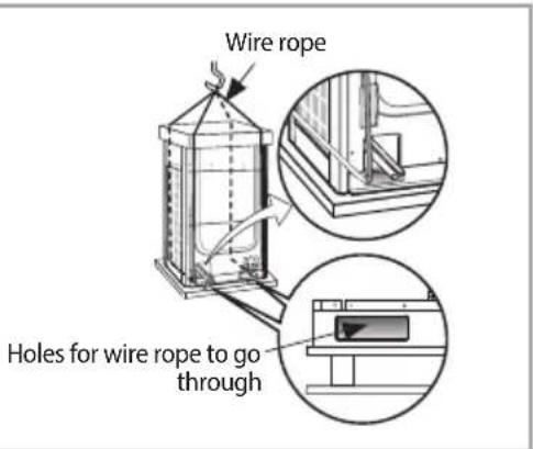
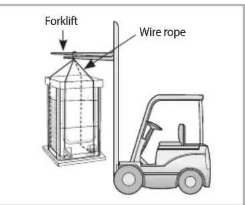
When moving with a crane
▶ Fasten the wire rope as shown in the figure.
▶ To protect damage or scratches, insert a piece of cloth between the outdoor unit and the wire rope.
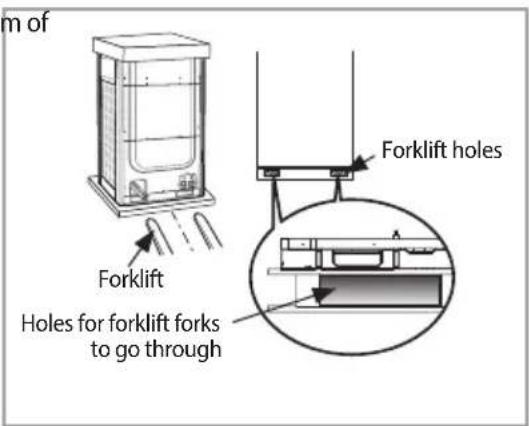
When moving with a forklift
- Carefully insert the forklift forks into the forklift holes at the bottom of the outdoor unit.
▶ Be careful with the forklift from damaging the product.
When moving the product without wooden pallet and the crane is not available for use
▶ Connect a wire rope to the outdoor unit as you would move it with a crane.
▶ Hang the wire rope to the forklift fork to move the outdoor unit.
Selecting installation location
Decide the installation location, with the consideration of the following conditions, under user's approval.
Place where hot discharge air or noise from the outdoor unit may not disturb the neighbor (Especially in residential areas, keep the operation hours in mind.)
Place where structure can bear the weight and vibration of the outdoor unit.
▶ Place with flat surface where rainwater does not settle or leak.
▶ Place where it is not exposed to strong wind.
▶ Well ventilated place with sufficient service place for repairs and maintenance. (Discharge duct can be purchased separately)
▶ Place where you can connect the refrigerant pipes between indoor and outdoor units within allowable distance.
Place where it allows easy waterproofing and draining work for the condensation water generated from the outdoor unit during heating operation.
▶ Place where there is no risk of inflammable gas leakage.
▶ Place where there is no direct influence of snow or rain.
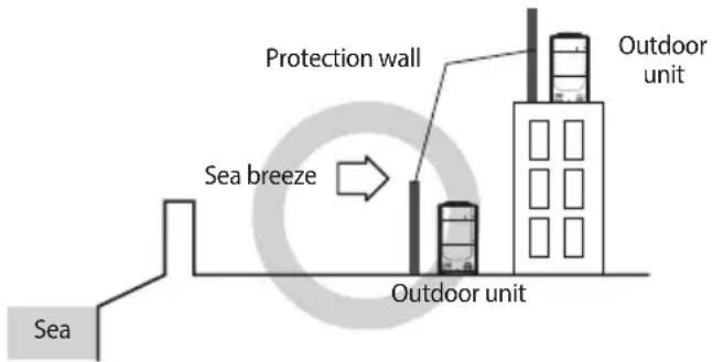
▶ Do not install the product in a place where it will be directly exposed to sea breeze.
- Consult an installation expert (or company) since you will need to take extra anti-corrosion measures if you need to install the product in a place where it can be exposed to direct sea breeze. (You have to remove dusts and salinity on the heat exchanger and apply designated rust inhibitor more than once a year.)
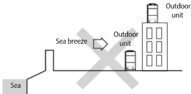
flowchart
graph LR
    A["Sea"] --> B["Sea breeze"]
    B --> C["Outdoor unit"]
    C --> D["Outdoor unit"]
* Caution when installing the product in seashore
- When installing the product in seashore, make sure to install it behind a structure (such as building) that can block the sea breeze or install protection wall around the outdoor unit.
- Make sure to install the product in a place where it allows smooth drainage.
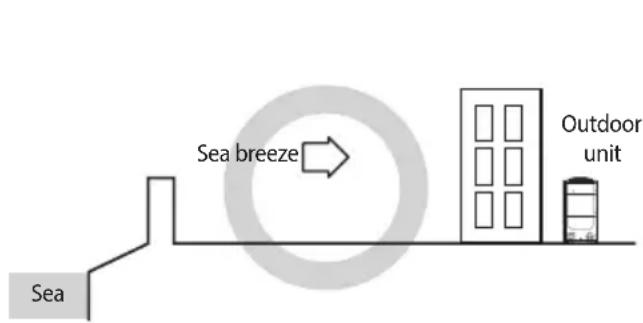
flowchart
graph LR
    A["Sea"] --> B["Sea breeze"]
    B --> C["Outdoor unit"]
flowchart
graph LR
    A["Sea"] --> B["Sea breeze"]
    B --> C["Protection wall"]
    C --> D["Outdoor unit"]
    D --> E["Outdoor unit"]
Protection wall should be constructed with a solid material that can block the sea breeze and the height and width of the wall should be 1.5 times larger than the size of the outdoor unit. (You must secure more than 700 mm(28 inch) of space between the protection wall and the outdoor unit for air circulation.)
Selecting installation location

- System air conditioner may cause static noise when listening to AM stations. Therefore, select an installation location for indoor unit where electrical wiring can be done while keeping certain distance from a radio, computer and stereo equipment.
- Especially, keep the unit at least 3 m (9.84 ft) away from the electrical equipment in an area with weak electromagnetic waves and put the main power cable and communication cables in a separately installed protection tube.
- Make sure that there is no equipment that generates electromagnetic waves. If not electromagnetic waves may cause problem to the control systems which may lead to air conditioner malfunction. (Example: Remote control sensor of the indoor unit may not receive the signal very well, due to ballast stabilizer of the lighting equipment.)
- In regions with heavy snowfall, make sure to install the outdoor unit where there is no concerns of direct snowfall on the outdoor unit. Also, build higher base support so that accumulated snow does not block the air inlet or the heat exchanger.
- R-410A refrigerant is a safe, nontoxic and nonflammable refrigerant. However, if the place holds any concerns for exceeding dangerous level of refrigerant concentration in case of refrigerant leakage, extra ventilation system is required.
- When you install the outdoor unit in a high places such as roof, install fence or guardrail around it. When there is no fence or guardrail, service person could fall.
- Do not install the product in places where corrosive gases such as sulfur oxides, ammonia, and sulfurous gas are produced. (e.g. Toilet outlet, ventilation opening, sewage works, dyeing complex, cattle shed, sulfuric hot spring, nuclear power plant, ship etc.) When installing the product in those places, contact an installation specialty store as the copper pipe and brazing part will need additional corrosion proof or anti-rust additive to prevent corrosion.
- Make sure to keep any inflammable materials (such as wooden materials, oil etc.) around the outdoor unit. When there's fire, those inflammable material will easily catch the fire and may pass it on to the product.
- Depending on the condition of power supply, unstable power or voltage any cause malfunction of the parts or control system. (At the ship or places using power supply from electric generator...etc)
• Make sure to install MCU when using HR products. - When you select the location to install MCU, the location is far away from indoor rooms because the refrigerant running of MCU may create noise.
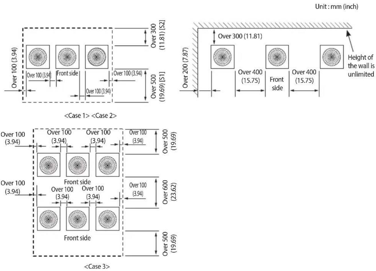
Space requirement for installation
▶ Space requirement was decided based on following conditions; Cooling mode, outdoor temperature of 35 ^ ( 95 ^ ). Larger space is required if the outdoor temperature is higher than 35 ^ ( 95 ^ ) or if the place is heated easily by quantity of solar radiation.
▶ When you secure installation space, consider path for people and the direction of the wind.
▶ Secure installation space as shown in the below illustration, considering ventilation and the service space.
▶ If the installation space is narrow, installer or other worker may get injured during work and may also cause problem to the product.
If you install multiple number of outdoor units in one space, make sure to secure enough ventilation space if there's any walls around the product that may disturb the air flow. If enough ventilation space is not secured, product may malfunction.
▶ You may install the outdoor units with 20 mm (0.79 inch) of space between the product, but product's performance may decrease depending on the installation environment.
Single installation
![Over 100 (3.94) Front side Over 100 (3.94) Over 500 (19.69) [S1] Over 100 (3.94) [S2] Over 300 (11.81) Front side Over 100 (3.94) Height of the wall is unlimited Unit: mm (inch)](/content/2026/05/1053352/images/d9fb019dca09e91412564aaf549ad353aeea52627257755710b89d1cec425a33.jpg)
Space requirement for installation
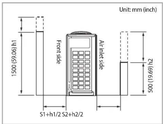
Module installation
* For
• Height of the wall on the front side should not be higher than 1500 mm (4.92 ft).
• Height of the wall on the air inlet side should not be higher than 500 mm (1.64 ft).
• Height of the wall on the side is not limited.
- If the height of the wall exceeds by certain value (h1, h2), additional clearance [(h1)/2, (h2)/2 : Half of the exceeded distance] should be added to the service space (S1, S2).
Accessories
Accessories
▶ You must keep following accessories until the installation is finished.
▶ Hand over the installation manual to the customer after finishing the installation.
| Installation manual (1) Packing socket (1) | |
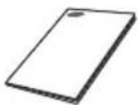 |  |
* Model with packing socket : AM140/240/260*XV*HH
* Socket can be different depending on the model.
Optional accessories
▶ Following optional accessories are needed for connecting pipes between the indoor and outdoor units.
| Classification Model | Name Specification | |
| Y-Joint | MXJ-YA1509M 15.0 kW (51.2 MBH) and below | |
| MXJ-YA2512M Over 15.0 kW ~ 40.0 kW (51.2 ~ 136.5 MBH) and below | ||
| MXJ-YA2812M Over 40.0 kW ~ 45.0 kW (136.5 ~ 153.5 MBH) and below | ||
| MXJ-YA2815M Over 45.0 kW ~ 70.3 kW (153.5 ~ 239.9 MBH) and below | ||
| MXJ-YA3419M Over 70.3 kW ~ 98.4 kW (239.9 ~ 335.8 MBH) and below | ||
| MXJ-YA4119M Over 98.4 kW ~ 135.2 kW (335.8 ~ 461.3 MBH) and below | ||
| MXJ-YA4422M Over 135.2 kW (461.3 MBH) | ||
| Y-Joint (Only H/R) | MXJ-YA1500M 22.4 kW (76.4 MBH) and below | |
| MXJ-YA2500M Over 22.4 kW ~ 70.3 kW (76.4 ~ 239.9 MBH) and below | ||
| MXJ-YA3100M Over 70.3 kW ~ 135.2 kW (239.9 ~461.3 MBH) and below | ||
| MXJ-YA3800M Over 135.2 kW (461.3 MBH) | ||
| Distribution header | MXJ-HA2512M 45.0 kW (153.5 MBH) and below (for 4 rooms) | |
| MXJ-HA3115M 70.3 kW (239.9 MBH) and below (for 8 rooms) | ||
| MXJ-HA3819M Over 70.3 kW ~ 135.2 kW (239.9 ~ 461.3 MBH) and below (for 8 rooms) | ||
| Y-Joint- Outdoor unit | MXJ-TA3819M | 135.2 kW (461.3 MBH) and below |
| MXJ-TA4422M | 140.2 kW (478.4 MBH) and Over | |
| Y-Joint (Only H/R)- Outdoor unit | MXJ-TA3100M | 135.2 kW (461.3 MBH) and below |
| MXJ-TA3800M | 140.2 kW (478.4 MBH) and Over | |
* If you use an indoor unit with no internal EEV(Electric Expansion Valve), you will need an EEV kit.
* Only use the genuine accessories listed in above table and do not use imitated accessories.
Base construction and installation of the outdoor unit

- Make sure to remove the wooden pallet before installing the outdoor unit. If you do not remove the wooden pallet, there is risk of fire during welding the pipes. If the outdoor unit is installed with wooden pallet on, and it was used for long period time, wooden palette may break and cause electrical hazard or high pressure may damage the pipes.
* Fix an outdoor unit firmly on the base ground with anchor bolts.
* Manufacturer is not responsible for the damage occurred by not following the installation standards.
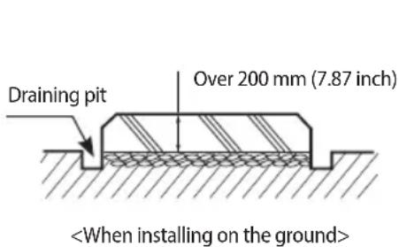
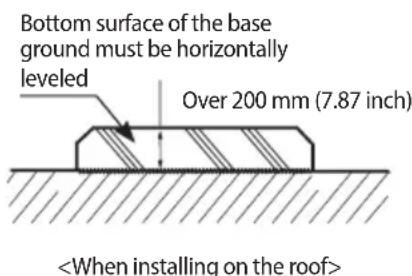
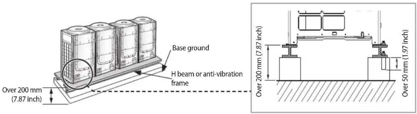
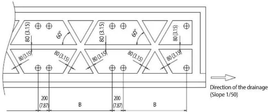
- Make sure that the height of the base ground is 200 mm (7.87 inch) or higher to protect the outdoor unit from rain water or other external conditions. Also, install a draining pit around the base ground and connect the drain pipe to the drainage.
- Considering the vibration and weight of the outdoor unit, strength of the base ground must be strong to prevent noise and the top surface of it should be flat.
- Base ground should be 1.5 times larger than the bottom of the outdoor unit.
- Outdoor unit must be fixed firmly so that it can withstand the wind speed of 30 m/s (67.11 MPH). If you cannot fix the outdoor unit on the base ground, fix it by side or use extra structure.
- In heating operation, defrost water may form so you must really care about the drainage and waterproofing the floor. To prevent defrost water from stagnating or freezing, construct a drainage with over 1/50 slope. (Ice may form on the floor in winter time.)
- It is necessary to add wire mesh or steel bar during concrete construction for the base ground to prevent damages or cracks.
- When installing multiple outdoor units at the same place, construct a H beam or an anti-vibration frame on the base ground to install the outdoor unit.
- After installing a H beam or an anti-vibration frame, apply corrosion protection and other necessary coating.
- When concrete construction for outdoor unit installation is completed, install an anti-vibration pad (t=20 mm (0.79 inch) or more) or an anti-vibration frame to prevent vibration of the outdoor unit from transferring to the base ground.
- Place the outdoor unit on a H beam or an anti-vibration frame and fix it with the bolt, nut and washer. (The bearing force has to be over 3.5 kN)
Base ground construction
Outdoor unit installation
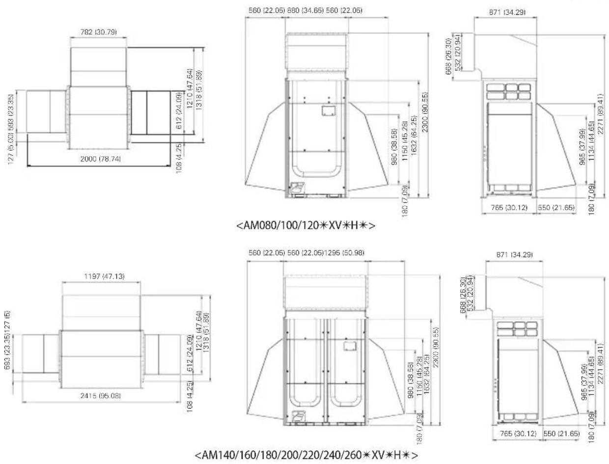
Outdoor unit base mount and anchor bolt position
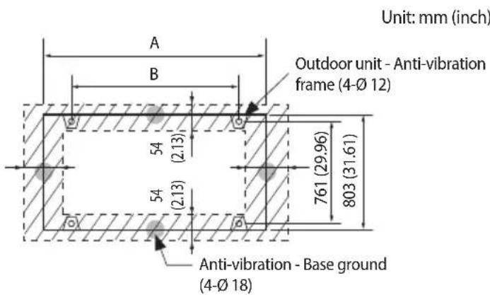
Unit: mm (inch)
| Classification Small type Large type | ||
| Models | AM080/100/120*XV*H* | AM140/160/180/200/220/240/260*XV*H* |
| A 880 (34.65) 1,295 (50.98) | ||
| B 740 (29.13) 1,150 (45.28) | ||
* Refer to the blueprints in technical data book to make a holes for connecting the anti-vibration pad.
Base construction and installation of the outdoor unit
Examples of draining work
Construct the drainage ditch with reinforced concretes and make sure that water-proofing work is done.
For smooth draining of defrost water, make sure to apply 1/50 slope.
Construct a drainage around the outdoor unit to prevent the defrost water (from the outdoor unit) from stagnating, overflowing or freezing near the installation space.
When the outdoor unit is installed on the roof, check the strength and waterproof status of the roof.
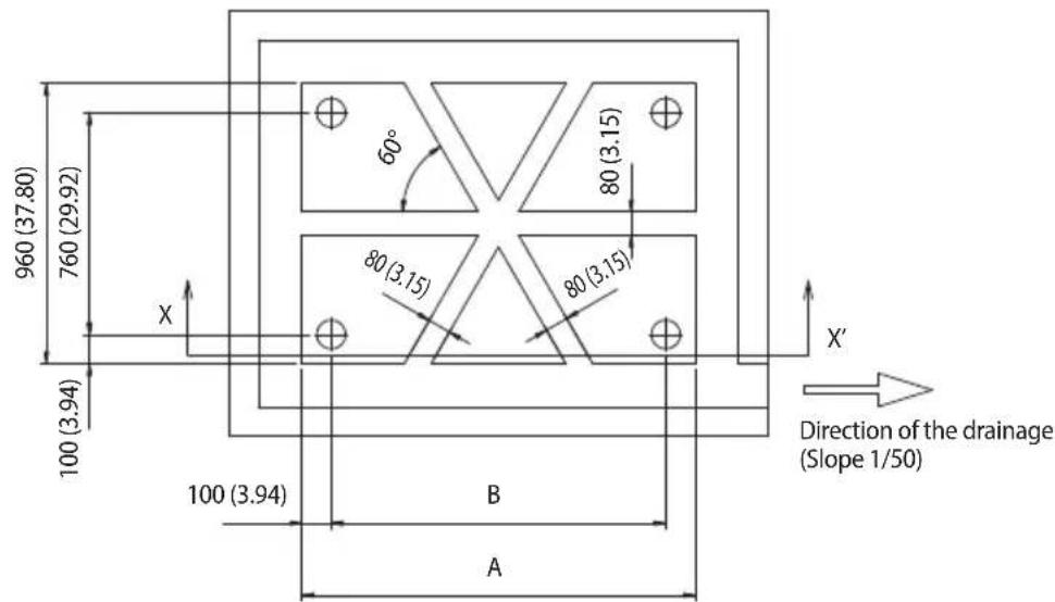
Unit: mm (inch)
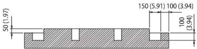
Unit: mm (inch)
| Classification Small type Large type | ||
| Models | AM080/100/120*XV*H* | AM140/160/180/200/220/240/260*XV*H* |
| A 940 (37.01) 1,350 (53.15) | ||
| B 740 (29.13) 1,150 (45.28) | ||

Cautions regarding on connecting the anchor bolt
▶ Tighten the rubber washer to prevent the bolt connection part of the outdoor unit from corroding.

Rubber washer
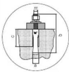
Anchor specification
| Size | Diameter of drill bit (a) | Anchor length (b) | Sleeve length (c) | Insert depth | Fastening torque |
| ∅ 10(∅ 0.39) | 14 mm(0.55 inch) | 75 mm(2.95 inch) | 40 mm(1.57 inch) | 50 mm(1.97 inch) | 30 N·m |
* Use the anchor bolts and nuts that is zinc plated or made of STS material. Regular anchor bolts or nuts may get damaged by corrosion.
Cautions regarding on connecting the pipe
▶ If you install the outdoor unit on the rooftop, check the strength and make sure to waterproof the rooftop.
▶ Construct draining pit around the base construction and pay attention to the drainage around the outdoor unit. (Condensation or defrost water may form during outdoor unit operation.)
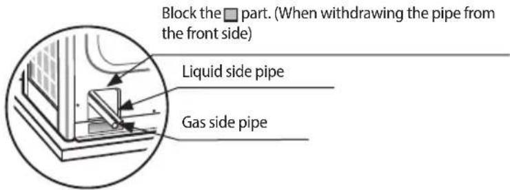
▶ If there's any possibility of small animals from entering the pipe outlet, block the outlet as shown in the illustration.
Cautions regarding on anti-vibration frame installation
▶ During installation, make sure there is no gap between the base ground and the supporting structures such as anti-vibration frame or H beam.
▶ Base ground must be constructed strongly to support the bottom part of the anti-vibration mount.
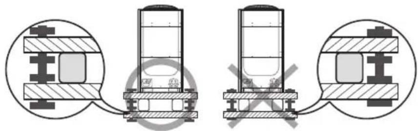
natural_image
Technical diagram showing mechanical assembly with cross-sectional views and no visible text or symbols▶ After installing the anti-vibration frame, untighten the fixing part on the top and bottom part of the frame.
Base construction and installation of the outdoor unit

Caution for installing discharge duct
▶ Static pressure of the discharge duct should be within the standard specification 78.45 Pa (0.315 W.G) when installing the duct.
If you remove the fan guard to install the discharge duct, make sure to install a safety net on the duct outlet. Foreign substance may enter into the product and there could be a risk of personal injury.
▶ Wear protection equipment at all times when making galvanized sheet metal duct, since the worker may get injured by the sharp parts.
When installing the outdoor unit under the tree or near forest, leafs may get into the product and cause problems on the product. Therefore, install a discharge duct to prevent foreign substance infiltration.
natural_image
Technical line drawing of a multi-chamber air conditioner unit (no text or symbols visible)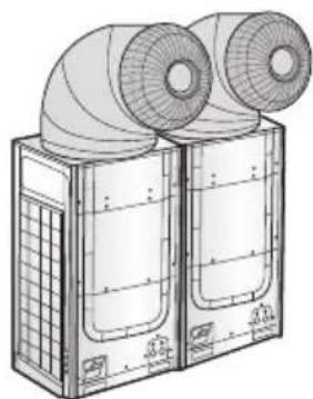
natural_image
Technical line drawing of a dual-panel air duct system with fans and ventilation grilles (no text or symbols)Installing the wind/snow prevention duct
Installing the outdoor unit around the obstacles
It is necessary to install a wind/snow prevention duct(field supply) to direct exhaust from the fan horizontally, when it is difficult to provide a minimum space of 2 m (6.56 ft) between the air outlet and a nearby obstacle.
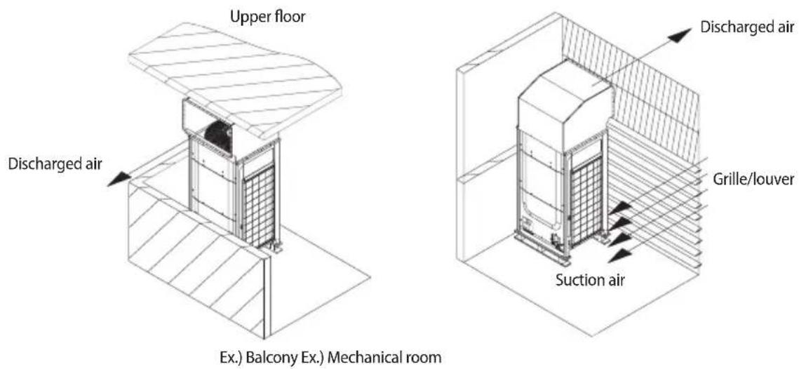
Installing the outdoor unit in cold region
In cold regions with lots of snowfall, install a snow prevention duct, as a sufficient countermeasure, to prevent snow from accumulating on the outdoor unit. When the snow prevention duct is not installed, frost may accumulate on the heat exchanger and heating operation may not work normally.
Air outlet of the duct should not be directed to the enclosed space.

CAUTION
Cautions regarding on installing the frame and selecting the base ground
- Height (h) of the frame and the base ground should be higher than the "heaviest expected snowfall".
- Area of the frame and the base ground should not be larger than the area of the outdoor unit. Snow may accumulate if the area of the frame or the base ground is larger.
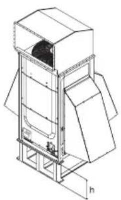
natural_image
Technical line drawing of a mechanical device with no visible text or symbols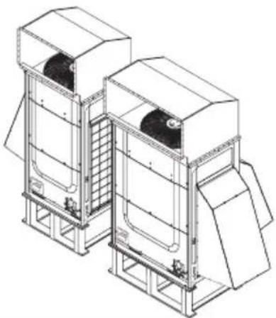
natural_image
Technical line drawing of two industrial storage units with heat sinks (no text or symbols)Installing the wind/snow prevention duct
Installing the outdoor unit in windy region
In windy regions such as near sea shores, protection wall or wind protection duct must be installed for normal operation of the outdoor unit. (Refer to the illustration of the snow prevention duct, for installing the wind protection duct.)
▶ Install the wind prevention duct with the consideration of major wind direction. If the direction of the discharge part is same as major direction of the wind, it could cause product's performance decrease.

Cautions regarding on installing the frame and selecting the base ground
• The base ground must be solid and the outdoor unit must be fixed with anchor bolts.
- Make sure to install outdoor unit in a place strong enough to withstand its weight. If the place cannot withstand the weight of the outdoor unit, outdoor unit may fall and cause personal injury.
- When installing on a rooftop subject to strong wind, countermeasures must be taken to prevent the unit from falling down.
• Use a frame that is resistant to corrosion.
Unit: mm (inch)
Refrigerant pipe installation

- When installing, make sure there is no leakage. When collecting the refrigerant, stop the compressor first before removing the connection pipe. If the refrigerant pipe is not properly connected and the compressor works with the service valve open, the pipe inhales the air and it makes the pressure inside of the refrigerant cycle abnormally high which may lead to explosion and injury.
Refrigerant pipe work
The length of refrigerant pipe should be as short as possible and the height difference between an indoor and outdoor unit should be minimized.
▶ Piping work must be done within allowable piping length, height difference, and the allowable length after branching.
The pressure of the R-410A is high. Use only certified refrigerant pipe and follow the installation method.
▶ After installing the pipes, calculate the total length of the pipe to check if additional refrigerant is needed. When you need to charge the additional refrigerant, make sure to use R-410A refrigerant.
▶ Use clean refrigerant pipe and there shouldn't be any harmful ion, oxide, dust, iron content or moisture inside pipe.
▶ Use tools and accessories that fit on R-410A only.
| Tool | Installation process/purpose | Compatibility with conventional tool | |
| Pipe cutter | flaring | Pipe cutting | Compatible |
| Flaring tool Pipe | Refrigerant pipe installation | ||
| Refrigerant machine oil | Apply refrigerant oil on flared part | Exclusive ether oil, ester oil, alkali benzene oil or synthetic oil | |
| Torque wrench | Connect flare nut with pipe | Compatible | |
| Pipe bender Pipe bending | |||
| Nitrogen gas | Air tightness test welding | Prevent oxidation within the pipe | |
| Welder Pipe welding | |||
| Manifold gage Air | tightness test ~ additional refrigerant charging | Vacuuming, charging refrigerant and checking operation | Need exclusive one to prevent mixture of R-22 refrigerant oil use and also the measurement is not available due to high pressure |
| Refrigerant charging hose | Need exclusive one since there is risk of refrigerant leakage or inflow of impurities | ||
| Vacuum pump Pipe drying | Compatible (Use products which contain the check valve to prevent the oil from flowing backward into the outdoor unit.) Use the one that can be vacuumed up to -100.7 kpa(5 Torr). | ||
| Scale for refrigerant charging | Gas leak test | Compatible | |
| Gas leak detector | Need exclusive one (Ones used for R-134a is compatible) | ||
| Flare nut | Must use the flare nut equipped with the product. Refrigerant leakage may occur when the conventional flare nut for R-22 is used. | ||
Refrigerant pipe installation
Selecting refrigerant pipe
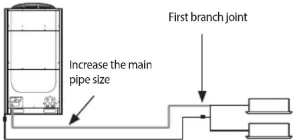
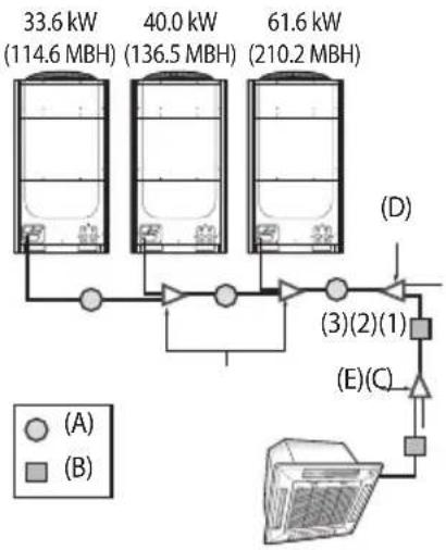
▶ Install the refrigerant pipe according to main pipe size of each outdoor unit capacity.
- When the pipe length (including elbow) between an outdoor unit and the farthest indoor unit exceeds 90 m (295 ft), you must increase the size of the pipe (main pipe) by one grade which connects between the outdoor unit to the first branch joint.
For H/R model, When the pipe length (including elbow) between an outdoor unit and the farthest indoor unit exceeds 90 m (295 ft), you must increase the size of the liquid pipe by one grade among the pipes(main pipe) which connects between the outdoor unit to the first branch joint.
flowchart
graph TD
    A["33.6 kW (114.6 MBH)"] --> B["40.0 kW (136.5 MBH)"]
    B --> C["61.6 kW (210.2 MBH)"]
    D["(A)"] --> E["Control Unit"]
    F["(B)"] --> E
    G["(D)"] --> H["(3)(2)(1)"]
    I["(E)(C)"] --> J["Control Unit"]
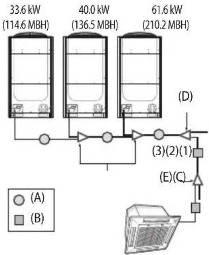
Ex.) 135.2 kW (461.3 MBH)
| Capacity (kW) No. | Pipe size [mm (inch)] | ||
| Liquid pipe Gas | pipe | ||
| 33.6 kW(114.6 MBH) | (1) ∅ 12.70 | (1/2) ∅ 28.58 (1 1/8) | |
| 73.6 kW(251.1 MBH) | (2) ∅ 19.05 | (3/4) ∅ 34.92 (1 3/8) | |
| 135.2 kW(461.3 MBH) | (3) ∅ 19.05 | (3/4) ∅ 41.28 (1 5/8) | |
Size of the pipe connected to the outdoor unit (A)
Select the size of the pipe according to the below table.
| Outdoor unit capacity [kW (MBH)] | Main pipe length within 90 m (295 ft) Size Up (Main pipe length over 90 m (295 ft)) | |||
| Liquid pipe [mm (inch)] | Gas pipe [mm (inch)] | Liquid pipe [mm (inch)] | Gas pipe [mm (inch)] | |
| 22.4 kW (76.4 MBH) | ∅ 9.52 (3/8) (7/8) ∅ 25.40 (1) | ∅ 19.05 (3/4) | ∅ 12.70 (1/2) | ∅ 22.22 (7/8) |
| 28.0 kW (95.5 MBH) ∅ 22.22 | ∅ 12.70 (1/2) | note1) | ||
| 33.6 kW (114.6 MBH) | ∅ 12.70 (1/2) | ∅ 28.58 (1 1/8) | ∅ 15.88 (5/8) | ∅ 28.58 (1 1/8) |
| 40.0 kW (136.5 MBH) | ||||
| 45.0 kW (153.5 MBH) | ∅ 31.75 (1 1/4) note2) | |||
| 50.4 kW (172.0 MBH) | ∅ 15.88 (5/8) ∅ 19.05 (3/4) | |||
| 56.0 kW (191.1 MBH) | ||||
| 61.6 kW (210.2 MBH) | ||||
| 67.2 kW (229.3 MBH) | ∅ 34.92 (1 3/8) ∅ 38 | 10 (1 1/2) | note3) | |
| 73.4 kW ~ 84.0 kW (251.1 MBH ~ 286.6 MBH) | ∅ 19.05 (3/4) ∅ 22.22 (7/8) ∅ 41.28 (1 5/8) | |||
| 89.6 kW ~ 95.2 kW (305.7 MBH ~ 324.8 MBH) | ||||
| 101.6 kW (346.7 MBH) | ∅ 41.28 (1 5/8) | |||
| 106.6 kW ~ 135.2 kW (363.7 MBH ~ 461.3 MBH) | ||||
| 140.2 kW ~ 168.2 kW (478.4 MBH ~ 573.9 MBH) | ∅ 53.98 (2 1/8) | |||
| 173.6 kW ~ 224.8 kW (592.3 MBH ~ 767.0 MBH) | ∅ 22.22 (7/8) ∅ 53.98 (2 1/8) ∅ 25.40 (1) | ∅ 22.22 (7/8) ∅ 53.98 (2 1/8) ∅ 25.40 (1) | note1) | |
Note1) If ∅ 25.40mm (∅ 1") pipe is not available on site, use ∅ 28.58mm (∅ 1 1/8") pipe.
Note2) If ∅ 31.75mm (∅ 1 1/4") pipe is not available on site, use ∅ 34.92mm (∅ 1 3/8") pipe.
Note3) If ∅ 38.10mm (∅ 1 1/2") pipe is not available on site, use ∅ 41.28 (∅ 1 5/8") pipe.
Refrigerant pipe installation
Size of the pipe between branch joints (B)
Select the pipe size according to the sum of indoor unit capacity which will be connected after the branch.
* However, if the size of the pipe between branch joints (B) is bigger than the size of the pipe connected to the outdoor unit (A), apply the pipe size (A).
| Indoor unit capacity [kW (MBH)] | Branch pipe length within 45 m (147.64 ft) note1) | Branch pipe length between 45~90 m (147.64~295.28 ft) note1) | ||
| Liquid pipe [mm (inch)] | Gas pipe [mm (inch)] | Liquid pipe [mm (inch)] | Gas pipe [mm (inch)] | |
| 15.0 kW (51.2 MBH) and below | ∅ 9.52 (3/8) | ∅ 15.88 (5/8) | ∅ 12.70 (1/2) | ∅ 19.05 (3/4) |
| Over 15.0 kW~22.4 kW (51.2 ~ 76.4 MBH) and below | ∅ 19.05 (3/4) ∅ 22.22 (7/8) | |||
| Over 22.4 kW~28.1 kW (76.4 ~ 95.9 MBH) and below | ∅ 22.22 (7/8) ∅ 25.40 (1) | note2) | ||
| Over 28.1 kW~40.0 kW (95.9 ~ 136.5 MBH) and below | ∅ 12.70 (1/2) | ∅ 28.58 (1 1/8) | ∅ 15.88 (5/8) | ∅ 28.58 (1 1/8) |
| Over 40.0 kW~45.0 kW (136.5 ~ 153.5 MBH) and below | ∅ 31.75 (1 1/4) note3) | |||
| Over 45.0 kW~63.3 kW (153.5 ~ 216.0 MBH) and below | ∅ 15.88 (5/8) ∅ 19.05 (3/4) | ∅ 38.10 (1 1/2) | ||
| Over 63.3 kW~70.3 kW (216.0 ~ 239.9 MBH) and below | ∅ 34.92 (1 3/8) ∅ 38.10 (1 1/2) | note4) | ||
| Over 70.3 kW~98.4 kW (239.9 ~ 335.8 MBH) and below | ∅ 19.05 (3/4) ∅ 22.22 (7/8) | |||
| Over 98.4 kW~135.2 kW (335.8 ~ 461.3 MBH) and below | ∅ 41.28 (1 5/8) | ∅ 41.28 (1 5/8) | ||
| Over 135.2 kW~169.0 kW (461.3 ~ 576.7 MBH) and below | ∅ 53.98 (2 1/8) | |||
| Over 169.0 kW (576.7 MBH) ∅ 22.22 | (7/8) ∅ 53.98 (2 1/8) ∅ 25.40 (1) | note2) | ||
Note1) Note on measuring distance between branch joints (B): You must measure the distance between first branch joint to the last indoor unit. (NOT from first joint to the last branch joint
Note2) If ∅ 25.40 mm (∅ 1") pipe is not available on site, use ∅ 28.58 mm (∅ 1 1/8") pipe.
Note3) If ∅ 31.75 mm (∅ 1 1/4") pipe is not available on site, use ∅ 34.92 mm (∅ 1 3/8") pipe.
Note4) If ∅ 38.10 mm (∅ 1 1/2") pipe is not available on site, use ∅ 41.28 mm (∅ 1 5/8") pipe.
Size of the pipe between the branch joint and the indoor unit
Make a selection according to outdoor unit capacity.
| Indoor unit capacity [kW (MBH)] | Pipe size (O.D. [mm (inch)]) | |
| Liquid pipe Gas pipe | ||
| 6.0 kW (20.5 MBH) and below ∅ 6.35 | (1/4) ∅ 12.70 (1/2) | |
| 7.1 kW ~ 16.0 kW (24.2 MBH ~ 54.6 MBH) and below | ∅ 9.52 (3/8) ∅ 15.88 (5/8) | |
| 20.0 kW ~ 23.0 kW (68.2 MBH ~ 78.5 MBH) and below | ∅ 9.52 (3/8) ∅ 19.05 (3/4) | |
| Over 23.0 Kw (78.5 MBH) ∅ 9.52 (3/8) ∅ 22.22 (7/8) | ||
Branch joint
▶ Branch joint between outdoor units (C)
| Classification Model name | Specification [kW (MBH)] | |
| Y-joint for outdoor unit (C) | MXJ-TA3419M 135.2 kW (461.3 MBH) and below | |
| MXJ-TA4122M Over 140.2 kW | (478.4 MBH) | |
▶ First branch joint (D)
Make a selection according to outdoor unit capacity.
| Classification | Outdoor unit capacity [kW (MBH)] | Model name of the branch joint |
| Y-joint (D) | 15.0 kW ~ 40.0 kW (51.2 ~ 136.5 MBH) and below | MXJ-YA2512M |
| 40.0 kW ~ 45.0 kW (136.5 ~ 153.5 MBH) and below | MXJ-YA2812M | |
| 45.0 kW ~ 70.3 kW (153.5 ~ 239.9 MBH) and below | MXJ-YA2815M | |
| 70.3 kW ~ 98.4 kW (239.9 ~ 335.8 MBH) and below | MXJ-YA3419M | |
| 98.4 kW ~ 135.2 kW (335.8 ~ 461.3 MBH) and below | MXJ-YA4119M | |
| Over 135.2 kW (461.3 MBH) MXJ-YA4422M |
▶ Branch joint (E)
Select a branch joint according to the sum of indoor unit capacity which will be connected after the branch.
Refrigerant pipe installation
* However, if the size of the pipe between branch joints (E) is bigger than the size of the pipe connected to the outdoor unit (D), apply the pipe size (D).
1) Y-joint
| Classification Model name Specification [kW (MBH)] | |
| Y-joint (E) | MXJ-YA1509M 15.0 kW (51.2 MBH) and below |
| MXJ-YA2512M Over 15.0 kW ~ 40.0 kW (51.2 ~ 135.2 MBH) and below | |
| MXJ-YA2812M Over 40.0 kW ~ 45.0 kW (136.2 ~ 153.5 MBH) and below | |
| MXJ-YA2815M Over 45.0 kW ~ 70.3 kW (153.5 ~ 239.9 MBH) and below | |
| MXJ-YA3419M Over 70.3 kW ~ 98.4 kW (239.9 ~ 335.8 MBH) and below | |
| MXJ-YA4119M Over 98.4 kW ~ 135.2 kW (335.8 ~ 461.3 MBH) and below | |
| MXJ-YA4422M Over 135.2 kW (461.3 MBH) | |
2) Distribution header
| Classification Model name | Specification [kW (MBH)] | |
| Distribution header (E) | MXJ-HA2512M 45.0 kW | (153.5 MBH) and below (for 4 rooms) |
| MXJ-HA3115M 70.3 kW | (239.9 MBH) and below (for 8 rooms) | |
| MXJ-HA3819M | Over 70.3 kW ~ 135.2 kW (239.9 ~ 461.3 MBH) and below (for 8 rooms) |
H/P
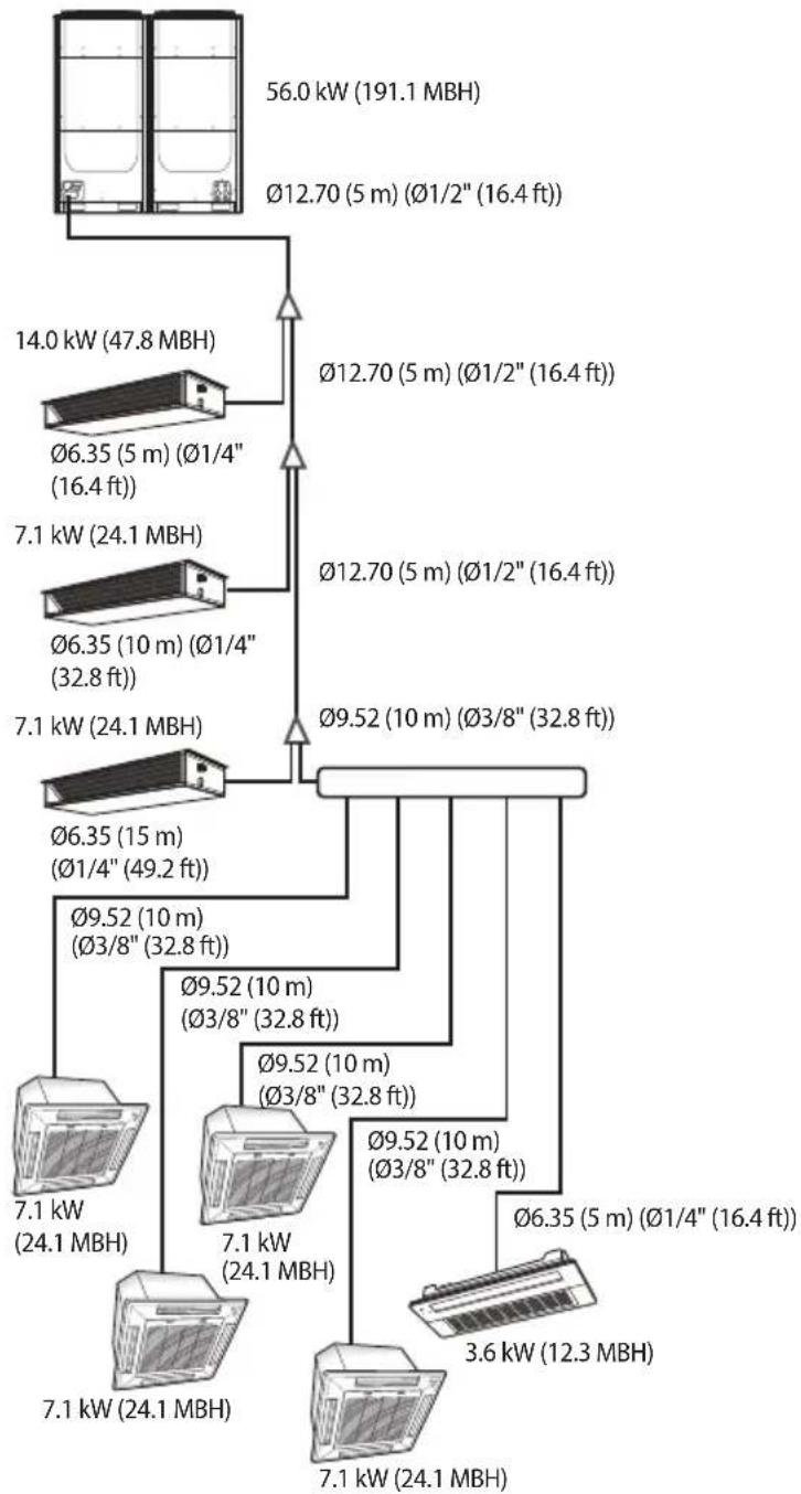
network
| Device | Power (kW) | Distance (m) | Capacity (ft) | | :--- | :--- | :--- | :--- | | 1 | 56.0 | 191.1 | | | 2 | 14.0 | 47.8 | | | 3 | 7.1 | 24.1 | | | 4 | 7.1 | 10 | | | 5 | 7.1 | 10 | | | 6 | 7.1 | 10 | | | 7 | 7.1 | 24.1 | | | 8 | 7.1 | 24.1 | | | 9 | 7.1 | 24.1 | | | 10 | 7.1 | 24.1 | | | 11 | 7.1 | 24.1 | | | 12 | 7.1 | 24.1 | | | 13 | 7.1 | 24.1 | | | 14 | 7.1 | 24.1 | | | 15 | 7.1 | 24.1 | | | 16 | 7.1 | 24.1 | | | 17 | 7.1 | 24.1 | | | 18 | 7.1 | 24.1 | | | 19 | 7.1 | 24.1 | | | 20 | 7.1 | 24.1 | | | 21 | 7.1 | 24.1 | | | 22 | 7.1 | 24.1 | | | 23 | 7.1 | 24.1 | | | 24 | 7.1 | 24.1 | | | 25 | 7.1 | 24.1 | | | 26 | 7.1 | 24.1 | | | 27 | 7.1 | 24.1 | | | 28 | 7.1 | 24.1 | | | 29 | 7.1 | 24.1 | | | 30 | 7.1 | 24.1 | | | 31 | 7.1 | 24.1 | | | 32 | 7.1 | 24.1 | | | 33 | 7.1 | 24.1 | | | 34 | 7.1 | 24.1 | | | 35 | 7.1 | 24.1 | | | 36 | 7.1 | 24.1 | | | 37 | 7.1 | 24.1 | | | 38 | 7.1 | 24.1 | | | 39 | 7.1 | 24.1 | | | 40 | 7.1 | 24.1 | | | 41 | 7.1 | 24.1 | | | 42 | 7.1 | 24.1 | | | 43 | 7.1 | 24.1 | | | 44 | 7.1 | 24.1 | | | 45 | 7.1 | 24.1 | | | 46 | 7.1 | 24.1 | | | 47 | 7.1 | 24.1 | - | | Note: The actual power values are not explicitly labeled in the code but are estimated based on the provided data source and the unit of each device's power output.Refrigerant pipe installation
Refrigerant pipe installation
▶ Basic amount of refrigerant within the outdoor unit
- Amount of additional refrigerant has to be calculated based on the sum of all liquid pipe length.
| Classification | AM080FXVAH* | AM100FXVAH* | AM120FXVAH* | AM140FXVAH* | AM160FXVAH* |
| Basic type 5.5 5.2 5.5 7.7 7.4 | |||||
| Classification | AM180FXVAH* | AM200FXVAH* | AM220FXVAH* | AM240HXVAH* | AM260HXVAH* |
| Basic type 8.7 8.4 8.4 14.3 14.3 | |||||
| Classification | AM080JXVGH* | AM100JXVGH* | AM120JXVGH* | AM160JXVGH* | AM180JXVGH* |
| Basic type 5.5 5.2 6.5 7.4 8.7 | |||||
| Classification AM200JXVGH* | |||||
| Basic type 8.4 | |||||
| Classification AM080KXVGHH AM100KXVGHH AM120KXVGHH AM140KXVGHH AM160KXVGHH | |||||
| Basic type 5.5 5.5 6.5 8.4 8.4 | |||||
| Classification AM180KXVGHH AM200KXVGHH AM220KXVGHH | |||||
| Basic type 8.4 8.4 8.4 | |||||
▶ Amount of additional refrigerant depending on the pipe size (a)
- Amount of additional refrigerant has to be calculated based on the sum of all liquid pipe length.
| Size of liquid pipe[mm(inch)] | 6.35 ( 1/4 ) | 9.52 ( 3/8 ) | 12.7 ( 1/2 ) | 15.88 ( 5/8 ) | 19.05 ( 3/4 ) | 22.22 ( 7/8 ) | 25.4 ( 1 ) | 28.58 ( 1 1/8 ) |
| Additional amount (kg/m) | 0.02 | 0.06 | 0.125 | 0.18 | 0.27 | 0.35 | 0.53 | 0.65 |
- For the indoor unit already connected to EEV kit, the additional refrigerant charging is 0.01 kg per feet regardless of the pipe size.
▶ Amount of additional refrigerant for each indoor unit (b)
(Unit : kg)
| Capacity (kW) Model | 1.7 | 2.2 | 2.8 | 3.6 | 4.5 | 5.6 | 6 | 7.1 | 9 | 11.2 | 12.8 | 14 | 22 | 28 | 500CMH | 1000CMH |
| Slim 1way cassette (JSF) (AM***FN1D*) | 0.25 | 0.25 | 0.25 | |||||||||||||
| 2way cassette (AM***FN2D*) | 0.31 | 0.47 | ||||||||||||||
| Global 4way cassette (AM***FN4D*) | 0.45 | 0.45 | 0.45 | 0.45 | 0.57 | 0.69 | 0.69 | |||||||||
| Floor standing unit (AM***FNFD*) | 0.22 | 0.32 | 0.32 | |||||||||||||
| ERV plus (AM***FNKD*) | 0.11 | 0.36 | ||||||||||||||
| Global mini 4way cassette (AM***FNND*) | 0.29 | 0.29 | 0.29 | 0.37 | 0.37 | 0.37 | ||||||||||
| Slim duct (AM***FNLD*) | 0.17 | 0.17 | 0.17 | 0.26 | 0.35 | 0.35 | 0.45 | 0.42 | 0.42 | 0.62 | 0.62 | |||||
| MSP duct-s (AM***FXMD*) | 0.24 | 0.24 | 0.24 | 0.28 | 0.28 | 0.28 | 0.32 | 0.54 | 0.68 | 0.68 | ||||||
| Ceiling (AM***FNCD*) | 0.27 | 0.27 | 0.27 | |||||||||||||
| Console (AM***FNJD*) | 0.24 | 0.24 | 0.24 | 0.36 | 0.36 | |||||||||||
| Neo forte (AM***FNTD*) | 0.24 | 0.24 | 0.24 | 0.36 | 0.36 | 0.36 | ||||||||||
| Neo forte (with EEV)(AM***FNQD*) | 0.68 | 0.68 0. | .68 1. | 18 1.18 | ||||||||||||
| HSP duct(AM***FNHD*) | 0.50 | |||||||||||||||
▶ If AHU kit is included among the indoor units, you must add 0.063 kg of refrigerant for every 1 kW (3.4 MBH) of the AHU capacity increase.(Unit : kg)
| Capacity (MBH) Model | 7.5 9 | 9.5 12 | 18 20 24 | 30 36 | 48 54 76 | 8 96 | |||||||
| 1way cassette (AM** *FN1DC*) | 0.25 | 0.25 0.25 | |||||||||||
| 2way cassette (AM** *FN2DC*) | 0.31 | 0.47 | |||||||||||
| Mini 4way cassette (AM** *FNNDC*) | 0.29 0.29 | 0.37 0.37 | |||||||||||
| 4way cassette (AM** *FN4DC*) | 0.45 | 0.45 | 0.45 0.69 | 0.69 0.69 | |||||||||
| 360 cassette (AM** *KN4DC*) | 0.45 | 0.45 | 0.45 | 0.45 | 0.69 | 0.69 | 0.69 | ||||||
| Slim duct (AM** *FNLDC*) | 0.35 | 0.35 | 0.35 | 0.45 | 0.45 | 0.42 | 0.42 | 0.62 | |||||
| MSP duct (AM** *NMDC*) | 0.28 | 0.28 0.54 | 0.54 0.68 | 0.91 | |||||||||
| HSP duct (AM** *FNHDC*) | 0.68 0.68 | 1.18 | 1.18 | ||||||||||
| Wall mounted (AM** *FNTDC*) | 0.24 | 0.24 0.24 | 0.36 0.36 | 0.36 | |||||||||
| Ceiling (AM** *FNCDC*) | 0.39 | 0.39 |
▶ If AHU Kit is included among the indoor units, add 0.018 kg of refrigerant for every 1 MBH of AHU capacity increase
Refrigerant pipe installation
▶ Method to calculate total amount of additional refrigerant
- Amount of additional refrigerant depending on the pipe length (a)
- Amount of additional refrigerant for each indoor unit ( ) = (Amount of additional refrigerant for each connected indoor unit) ※ Refer to the table
- Total amount of additional refrigerant = ⓐ + ⓑ
* Sum of total amount of additional refrigerant and the basic amount of refrigerant should not exceed 100 kg. If the refrigerant exceeds 100 kg, separate the module so that weight of the refrigerant doesn't exceed 100 kg.
Ex.) AM200FXVAH*, basic amount of refrigerant 8.4 kg, therefore total amount of additional refrigerant (a+b) should not exceed 91.6 kg.
▶ Example of calculation
| Classification | Size of liquid pipe (mm, inch) | Length (m, ft) | Unit amount of refrigerant (kg/m) | Amount of additional refrigerant (kg) | Total amount of additional refrigerant (kg) |
| 1 | 2 | 1×2 | Σ(1×2) | ||
| Liquid pipe (a) | ∅ 6.35, ∅ 1/4 35, 1 | 14.82 0.02 0.7 | a 5.575 | ||
| ∅ 9.52, ∅ 3/8 50, 1 | 64.04 0.06 3.0 | ||||
| ∅ 12.7, ∅ 1/2 15, 4 | 9.21 0.125 | 1.875 |
| Classification | Model name of indoor unit | Number of units | Unit amount of refrigerant (kg/EA) | Amount of additional refrigerant (kg) | Total amount of additional refrigerant (kg) |
| 1 | 2 | 1 × 2 | (1 × 2) | ||
| Indoor unit (b) | 4way cassette (AM071FN4D*) (AM024FN4DC*) | 4 0.45 1.8 | 3.57 | ||
| Slim duct (AM140FNLD*) (AM048FNLDC*) | 1 0.62 | 0.62 | |||
| Slim duct (AM071FNLD*) (AM024FNLDC*) | 2 0.45 0.9 | ||||
| 1way cassette (AM036FN1D*) (AM012FN1DC*) | 1 0.25 | 0.25 |
- Total amount of refrigerant (a+b)=5.575+3.57=9.145(kg)
Temper grade and minimum thickness of the refrigerant pipe
| Outer diameter(mm, inch) | Minimum Thickness(mm, inch) | Temper grade |
| ∅ 6.35, ∅ 1/4 0.70, 0.028 | Annealed | |
| ∅ 9.52, ∅ 3/8 0.70, 0.028 | ||
| ∅ 12.7, ∅ 1/2 0.80, 0.031 | ||
| ∅ 15.88, ∅ 5/8 1.00, 0.039 | ||
| ∅ 19.05, ∅ 3/4 0.90, 0.035 | Drawn | |
| ∅ 22.22, ∅ 7/8 0.90, 0.035 | ||
| ∅ 25.4, ∅ 1 1.00, 0.039 | ||
| ∅ 28.58, ∅ 1 1/8 1.10, 0.043 | ||
| ∅ 31.75, ∅ 1 1/4 1.10, 0.043 | ||
| ∅ 34.92, ∅ 1 3/8 1.21, 0.048 | ||
| ∅ 38.10, ∅ 1 1/2 1.35, 0.053 | ||
| ∅ 41.28, ∅ 1 5/8 1.43, 0.056 | ||
| ∅ 44.45, ∅ 1 3/4 1.60, 0.063 | ||
| ∅ 50.80, ∅ 2 2.00, 0.079 | ||
| ∅ 53.98, ∅ 2 1/8 2.10, 0.083 |

- For pipes larger than ∅ 19.05 (∅ 3/4), drawn type (C1220T-1/2H or C1220T-H) type copper pipe must be used. If a annealed type (C1220T-O) copper pipe is used, pipe may break due to its low pressure resistance and cause personal injury.
Refrigerant pipe installation
Keeping refrigerant pipe
To prevent foreign materials or water from entering the pipe, storing method and sealing method (especially during installation) is very important. Apply correct sealing method depending on the environment.
| Exposure place Exposure time Sealing type | ||
| Outdoor | Longer than one month Pipe pinch | |
| Shorter than one month Taping | ||
| Indoor - Taping | ||
Refrigerant pipe welding and safety information

Important information for refrigerant pipe work
• Make sure there is no moisture inside the pipe.
• Make sure there are no foreign substances and impurities in the pipe.
• Make sure there is no leakage.
• Make sure to follow the instruction when welding or storing the pipe.
Nitrogen flushing welding
When welding the refrigerant pipes, flush them with nitrogen gas as shown in the picture.
▶ If you do not perform nitrogen flushing when welding the pipes, oxide may form inside the pipe. It can cause the damage of the important parts such as compressor and valves etc.
Adjust the flow rate of the nitrogen flushing with a pressure regulator to maintain 0.0577.56 inch ^3 /h) or less.
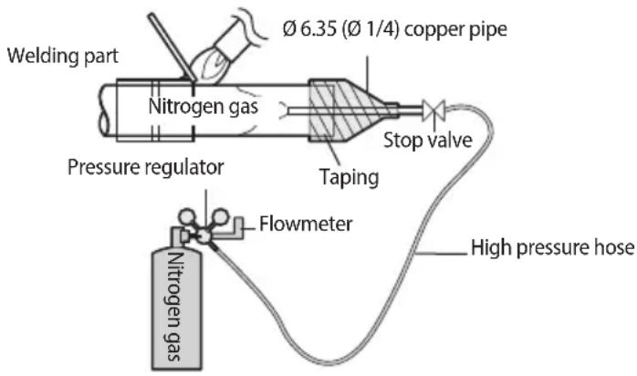
Direction of the pipe when welding
Direction of the pipe should be headed downward or in a sideways when welding.
▶ Avoid welding the pipe with pipe direction heading upward.

- When you test gas leakage after welding the pipes, use a designated solution for gas leakage detection. If you use the detection solution that includes sulfuric ingredient, it may cause corrosion to the pipes.
Cutting or flaring the pipes
- Make sure that you prepared the required tools.
▶ Pipe cutter, Deburring tool, flaring tool and pipe holder, etc.
- If you want to shorten the pipe, cut it with a pipe cutter ensuring that the cut edge remains at 90^ with the side of the pipe.
▶ Refer to below illustrations for correct and incorrect examples of cut edges.
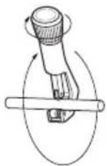
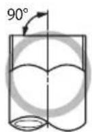
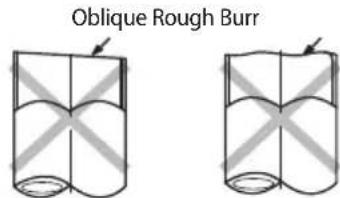
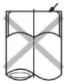
-
To prevent a gas leak, remove all burrs at the cut edge of the pipe using a Deburring tool.
-
Carry out flaring work using flaring tool as shown below.
[Flaring tools]
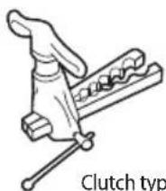
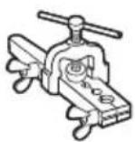
Clutch type Wing nut type
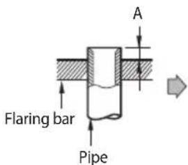
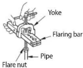
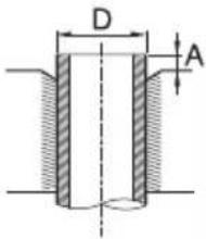 | Pipe diameter [D (mm, inch)] | Depth of flaring part [D(mm, inch)] | |||
| Using flaring tool for R-410A | Using conventional flaring tool | ||||
| Clutch type Wing nut type | |||||
| ∅ 6.35, ∅ 1/4 | 0~0.5, 0~0.02 1.0~1 | 5, 0.039~0.059 1.5~2.0, 0.059~0.079 | |||
| ∅ 9.52, ∅ 3/8 0~0.5, 0 | ~0.02 1.0~1.5, 0.039~0.05 | 9 1.5~2.0, 0.059~0.079 | |||
| ∅ 12.7, ∅ 1/2 0~0.5, 0 | ~0.02 1.0~1.5, 0.039~0.05 | 9 1.5~2.0, 0.059~0.079 | |||
| ∅ 15.88, ∅ 5/8 | 0~0.5, 0~0.02 1.0~1 | 5, 0.039~0.059 1.5~2.0, 0.059~0.079 | |||
- Check that you flared the pipe correctly.
▶ Refer to below illustrations for correct and incorrect examples of flared pipe.
Correct
Inclined
Damaged Surface
Cracked
Uneven Thickness

CAUTION
- If foreign matters or burrs are not removed after cutting pipe, refrigerant gas may leak.
- If foreign matters enter inside the pipe, important interior parts of the unit may get damaged or product efficiency will be reduced. So, the direction of pipe should be downward during pipe cutting or flaring.
Refrigerant pipe installation
Connecting the flared pipes
▶ Check if the flaring is properly done according to the standard size.
Align the center of the piping and tighten the flare nut with your hands. Then, tighten the flare nut with torque wrench in a direction of the arrow indicated in below illustration.
▶ Make sure to use ester oil to coat the flare connection section.
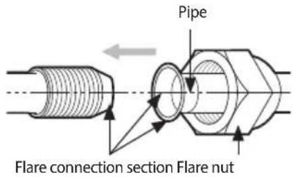
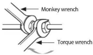
| Outer diameter (D) | Connection torque (N·m) | Flare dimension (L) | Flare shape [mm(inch)] | ||
| mm inch | mm inch | ||||
| ∅ 6.35 ∅ 1 | /4 14 ~ 18 8.7 | ~ 9.1 0.34 ~ 0.36 | 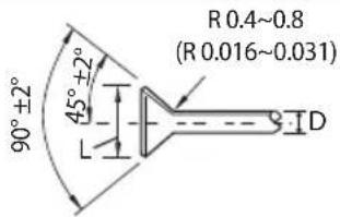 | ||
| ∅ 9.52 ∅ 3 | /8 34 ~ 42 12.8 | ~ 13.2 0.50 ~ 0.52 | |||
| ∅ 12.7 ∅ 1 | /2 49 ~ 61 16.2 | ~ 16.6 0.64 ~ 0.65 | |||
| ∅ 15.88 ∅ | /8 68 ~ 82 19.3 | ~ 19.7 0.76 ~ 0.78 | |||

- Blowing Nitrogen gas should be done when welding the pipe.
• Make sure to use the provided flare nut.
• Make sure that there are no cracks or twisted part when you need to bend the pipe.
• Do not fasten the flare nut with excessive strength. - R-410A is a high pressure refrigerant and there is a risk of refrigerant leakage if the flare connection is not coated with ester oil. Therefore, apply ester oil to coat the flare connection area.
Pipe installation for an outdoor unit
1. Direction of the pipe
Refrigerant pipe can be withdrawn from the front, left and right side. Take necessary method to install the pipes according to the condition of the installation site.
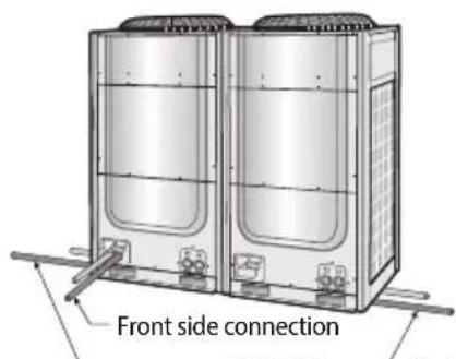
Right side connectionLeft side conr

Caution for using knock-out hole
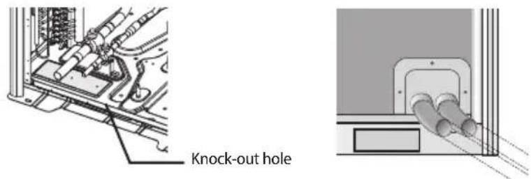
• Make sure to prevent any damages on the exterior of the outdoor unit.
- Remove all burrs around the knock-out hole and apply varnish on the cross section and edges of the knock-out hole to prevent rust.
- Use a cable protection tube and bushing to prevent a cable from being damaged when passing through a knock-out hole.
Refrigerant pipe installation
2. Connecting refrigerant pipe for outdoor unit
| Classification Front side connection Right/left (and bottom) side connection | ||
| Working process | First, remove the piping cover from the outdoor unit.Separate the knock-out hole that you are going to use. If you separate the knock-out hole that is going to be unused, small animals such as squirrels and rats may get into the unit through the hole.Fix the bottom side of the piping cover first and then fix the top part of it. | Separate the knock-out hole at the bottom side of the unit and install the pipe.After installing and insulating the pipe, close up the remaining holes. If not, small animals such as rats and squirrels may get inside the unit. |
| H/P | 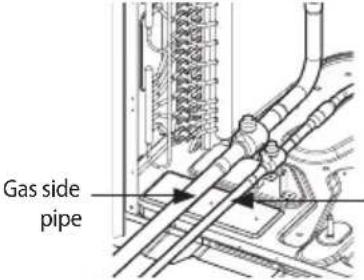 Liquid side pipe Liquid side pipe | 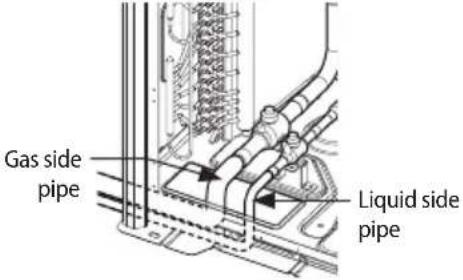 |

Caution for welding the pipe to an outdoor unit
- When welding the pipe, the unit may get damaged by the heat and flame from welding. Use a flame proofing cloth to protect the unit from a welding fire or flame. Sensor for detecting outside temperature is located on the left side of the welding part so be extra careful not to damage the sensor when welding.
- The O-ring and Teflon packing inside service valve may get damaged by the heat from welding. Wrap the bottom side of the service valve with a wet cloth and weld it as shown in the illustration. Also, water dripping from the wet cloth may interrupt the welding. Make sure the water does not drip from the wet cloth.
- Make sure that connected pipes does not interrupt each other or make contact with the product. (Vibration may cause damage to the pipes.)
- When removing the sealed pipe on the bottom side of the service valve, cut it with a pipe cutter first and then start the welding. When the sealed pipe is welded without cutting, you may get injured by the refrigerant within the pipe.
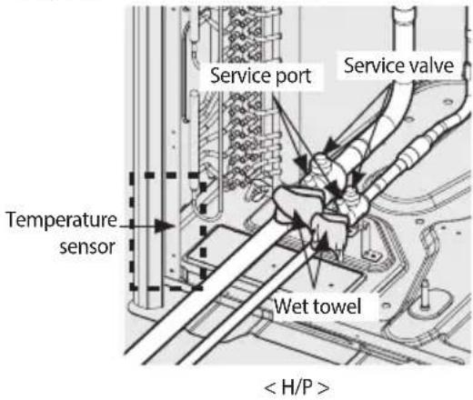
- Pipe installation between the outdoor units
▶ You will need branch joints, which is an optional accessory, for connecting in between outdoor units in order to combine outdoor units in module.
* For optimal distribution of the refrigerant, you must use Y-joint as branch joint for connecting outdoor units. (Do not use T-joint)
▶ When you install the outdoor units in module, there is no restriction of installation order among outdoor units.
▶ Height of the connection pipe should be same or lower than the ones connected to the outdoor units.
▶ Check the changes in comparison with the DVM II and III.
| Caution Correct installation Incorrect installation | ||
| Refrigerant pipes should be connected at the same or lower level than the ones connected to the outdoor unit. | 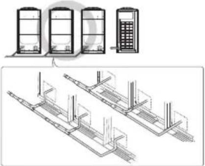 | 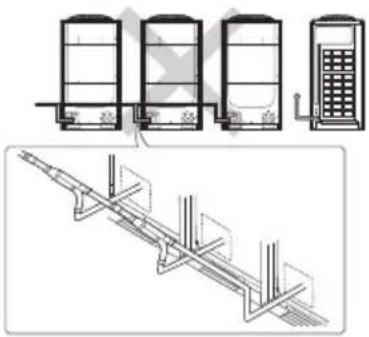 |
| Refrigerant pipes must be connected by the side of the product. | 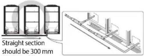 (11.81 inch) or more (11.81 inch) or more | 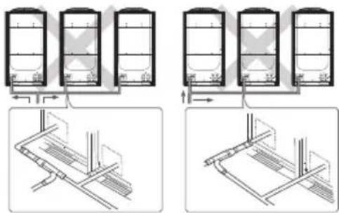 |
| Branch joint between outdoor units must be installed horizontally. | 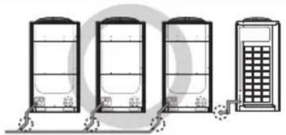 | 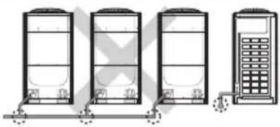 |
| When the piping length between outdoor unit and the branch joint exceeds 2 m (6.56 ft), install a vertical trap as show in the figure. | 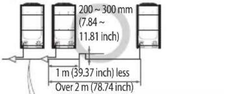 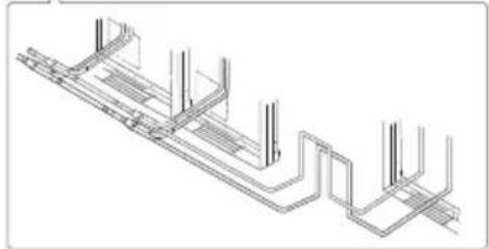 | 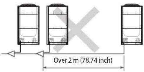 |
Refrigerant pipe installation
Examples of refrigerant pipe installation
H/P
- Using Y-joint
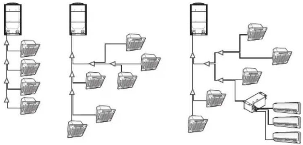
- Using distribution header
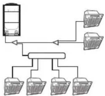
flowchart
graph TD
    A["Data Unit"] --> B["Processing Unit"]
    B --> C1["Device 1"]
    B --> C2["Device 2"]
    B --> C3["Device 3"]
    B --> C4["Device 4"]
    B --> C5["Device 5"]
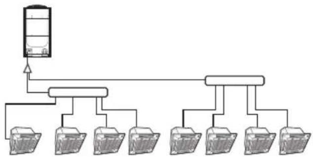
flowchart
graph TD
    A["Central Server"] --> B["Client 1"]
    A --> C["Client 2"]
    A --> D["Client 3"]
    A --> E["Client 4"]
    A --> F["Client 5"]
    A --> G["Client 6"]
    A --> H["Client 7"]
Allowable length of the refrigerant pipe and the installation examples
H/P
| Classification Single Installation Module installation | ||
| Installing only with Y-joint | Outdoor unit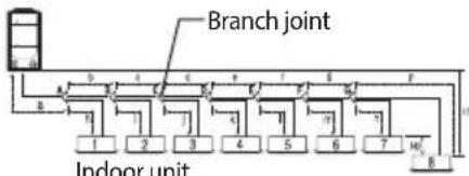 indoor unit indoor unit | Outdoor unit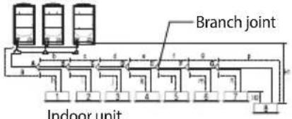 indoor unit indoor unit |
| Installing with Y-joint and distribution header | 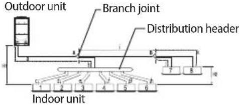 | Outdoor unit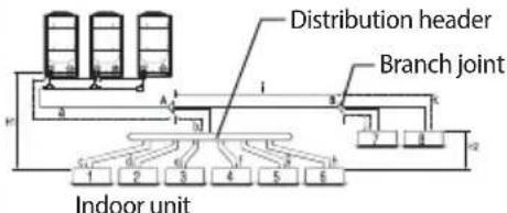 |
| Installing only with distribution header | Outdoor unit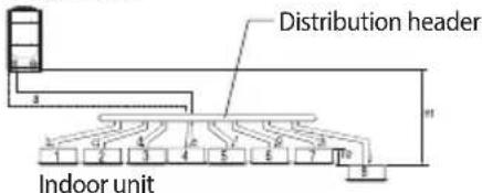 | Outdoor unit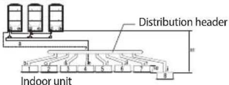 |
| Classification Example Remarks | ||||||
| Maximum allowable length of pipe | Outdoor unit ~ Indoor unit | Actual length (Equivalent length) | 200 m (656.17 ft) and below (220 m (721.78 ft) and below) | Installing only with Y-joint | a+b+c+d+e+f+g+p ≤ 200 m (656.17 ft)(220 m (721.78 ft)) | Equivalent length Y-joint: 0.5 m (1.64 ft), Distribution header: 1 m (3.28 ft) |
| Installing with Y-joint and distribution header | a+b+h ≤ 200 m (656.17 ft) (220 m (721.78 ft)), a+i+k ≤ 200 m (656.17 ft) (220 m (721.78 ft)) | |||||
| Installing only with distribution header | a+i ≤ 200 m (656.17 ft) (220 m (721.78 ft)) | |||||
| Total length of pipe (m) | 1000 m (3280.84 ft) or less | Installing only with Y-joint | a+b+c+d+e+f+g+h+u+j+k+l+m+n+p ≤ 1000 m (3280.84 ft) | - | ||
| Installing with Y-joint and distribution header | a+b+c+d+e+f+g+h+i+j+k ≤ 1000 m (3280.84 ft) | - | ||||
| Installing only with distribution header | a+b+c+d+e+f+g+h+i ≤ 1000 m (3280.84 ft) | - | ||||
| Outdoor unit ~ Outdoor unit (Module installation) | Pipe length | 10 m (32.80 ft) or less | r ≤ 10 m (32.80 ft), s ≤ 10 m (32.80 ft), t ≤ 10 m (32.80 ft) | 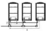 | ||
| Equivalent length | 13 m (42.65 ft) or less | r ≤ 13 m (42.65 ft), s ≤ 13 m (42.65 ft), t ≤ 13 m (42.65 ft) | ||||
| Maximum allowable height difference of pipe | Outdoor unit ~ Indoor unit | 110/110 m (360.89/360.89 ft) Note 2) | H1 ≤ 110/110 m (360.89/360.89 ft) | |||
| Indoor unit ~ Indoor unit | 50 m (164.04 ft) or less H2 | ≤ 50 m (164.04 ft) | ||||
| But, when AM * * *FNQD * is installed, H2 is 15 m (49.21 ft) or less | ||||||
Refrigerant pipe installation
| Classification Example Remarks | |||||
| Maximum allowable length after branch joint | First branch joint ~ Farthest Indoor unit | Pipe length | 45 m (147.64 ft) or less | b+c+d+e+f+g+p ≤ 45 m (147.64 ft), i ≤ 45 m (147.64 ft) | - |
| 45 ~ 90 m (147.64 ~ 295.28 ft) | Required conditions must be satisfied | Exclude H/R | |||
| EEV kit Model name Remarks | |||||
| EEV kit ~ Indoor unit | Actual pipe length | 2 m (6.56 ft) | MEV-E24SA | 1 indoor | Apply to products without EEV (Wall mount & ceiling) |
| MEV-E32SA | |||||
| 20 m (65.62 ft) or less | MXD-E24K132A | 2 indoorMXD-E24K200A | |||
| MXD-E32K200A | |||||
| MXD-E24K232A | 3 indoor | ||||
| MXD-E24K300A | |||||
| MXD-E32K224A | |||||
| MXD-E32K300A | |||||
* Please refer to the EEV Kit manual.
Note 1) Required condition
| Classification Condition Example | ||
| First branch joint ~ Farthest Indoor unit | 45 m (147.64 ft) ≤ b+c+d+e+f+g+p ≤ 90 m (295.28 ft): branch pipes (b, c, d, e, f, g) size must be increased by 1 grade | 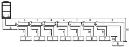 |
| Total length of extended pipe | If the size of pipe (main pipe), between the first branch joint and the outdoor unit, is not increased by 1 grade, a+(b+c+d+e+f+g)×2 +h+i+j+k+l+m+n+p ≤ 1000 m (3280.84 ft) | |
| If the size of pipe (main pipe), between the first branch joint and the outdoor unit, is increased by 1 grade, (a+b+c+d+e+f+g)×2 +h+i+j+k+l+m+n+p ≤ 1000 m (3280.84 ft) | ||
| Each Y-joint ~ Each indoor unit | h, i, j, ... p ≤ 45 m (147.64 ft) | |
| Difference between the distance of the outdoor unit to the farthest indoor unit and nearest indoor unit ≤ 45 m (147.64 ft), (a+b+c+d+e+f+g+p)-(a+h) ≤ 45 m (147.64 ft) | ||
Note 2) When indoor unit is located at higher level than outdoor unit, allowable height difference is 110 m(360.89 ft), (If the height difference is over 40 m(131.23 ft), contact your local dealer for more information.) but when the indoor unit is located at lower level than outdoor unit, allowable height difference is 110 m (360.89 ft) (If the height difference is over 50 m(164.04 ft), need to decide whether to install PDM kit or not.) Model name of the PDM kit : MXD-A38K2A, MXD-A12K2A, MXD-A58K2A
Installing the branch joints
Branch joints must be installed 'horizontally' or 'vertically'.
Horizontal installation
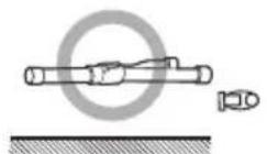
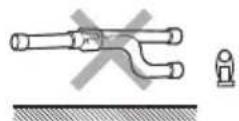
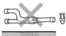
Vertical installation
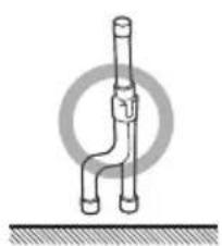
natural_image
Simple line drawing of a pipe fitting with a circular target symbol above (no text or labels)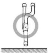
natural_image
Pure diagram of a pipe fitting with no text, numbers, or symbols
NOTE
- For A\~J type branch joints: Connect the branch joint to the connection pipe with the provided reducer.
- For K\~Z type branch joints: Cut the connection part of the branch joint or the provided socket, according to the diameter of the connection pipe, before connecting them.
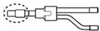
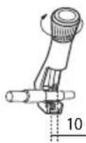
10 \~ 15 mm (0.39 \~ 0.59 inch)

CAUTION
• Install the branch joint within ±15^ of the horizon or vertical line.
• Make sure that the pipe is not bent at where it is connected to the branch joint.
- Keep a minimum straight line distance of 500 mm (19.69 inch) or more before connecting branch joint.
![Connect to other branch joint or indoor unit After branching Pipe connection Socket After branching Socket After branching Gas side/Liquid side branch joint Before branching Connect to indoor unit 30° Pipe (Main pipe) Minimum straight line [Over 500 mm (10-60 inch)]](/content/2026/05/1053352/images/f1c018d03143e1ccd1b25d8b982c943a4b5664d4e157c42d7f5d762792bf90e0.jpg)
* Install within ±15° of the horizon or vertical line.
![Pipe (Main pipe) Minimum straight line [Over 500 mm (19.69 inch)]](/content/2026/05/1053352/images/bc4c724dc1ec101798814c670c02160d691b9fad802f2cc753378d3e77c45c7e.jpg)
Refrigerant pipe installation
Installing the distribution header
- Select the reducer that fits the diameter of the pipe.
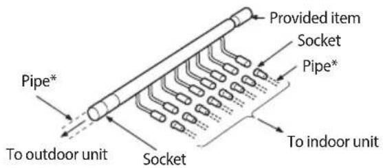
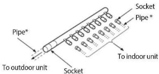
* Pipe : Separately purchased item
- If the number of connected indoor unit is fewer than ports on the distribution header, block the unused ports with caps.
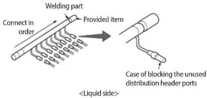
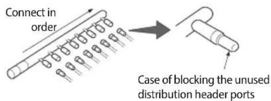

NOTE
• For A\~J type distribution header:
Connect the distribution header to the connection pipe with the provided reducer.
• For K\~Z type distribution headers :
Cut the provided socket, according to the diameter of the connection pipe, before connecting it.
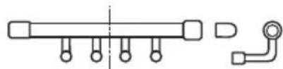
natural_image
Pure mechanical component diagram without any text, numbers, or symbols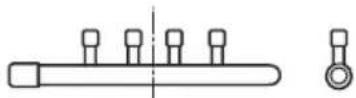
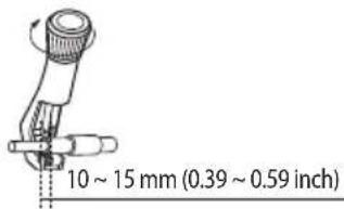

CAUTION
- Connect the indoor units in order, while respecting the direction of the arrow shown in the illustration.
- When indoor units are connected to same distribution head, indoor unit must be connected in order of their capacity, from largest to smallest.
- Install the distribution header horizontally.
▶ Install the distribution header horizontally so that its ports does not face down.
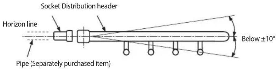
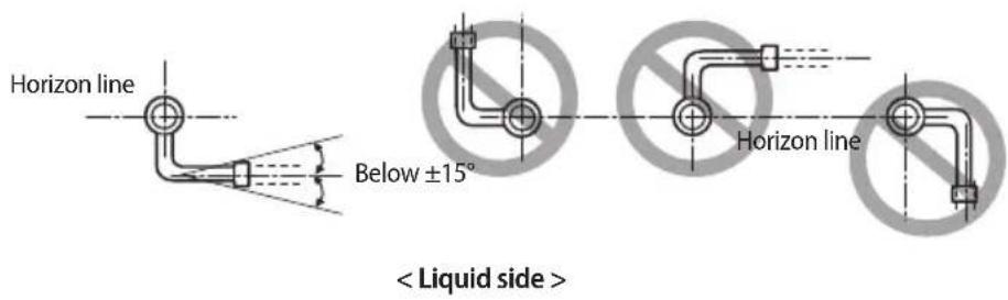
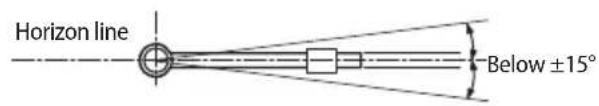
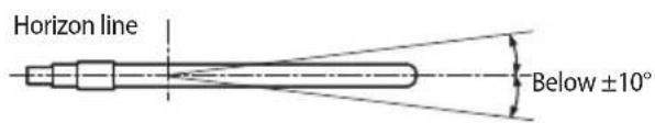
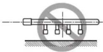
natural_image
Pure mechanical diagram showing a shaft with four vertical supports and a diagonal line, no text or symbols present.Installing the branch joint between outdoor units
Installation of outdoor joints
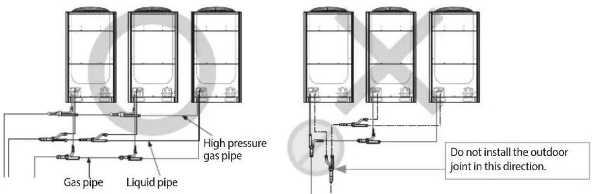
* High pressure gas pipe only applies to the H/R product.
Refrigerant pipe installation
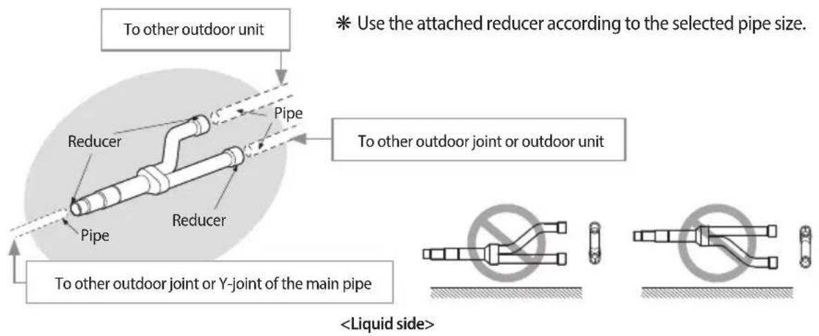

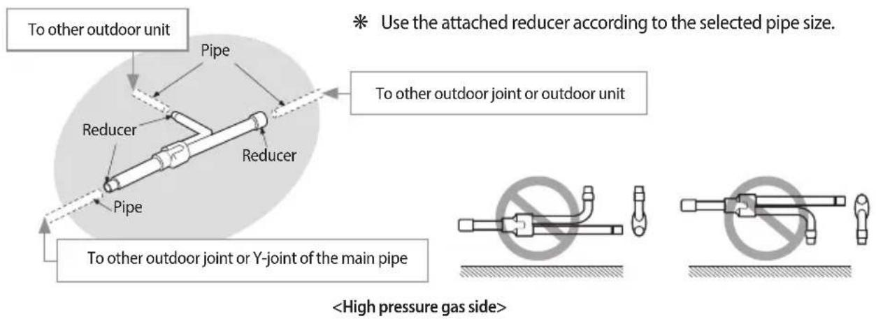

NOTE
- Connect the Outdoor joint to the pipe by cutting the outlet of the Outdoor joint or provided reducer properly.
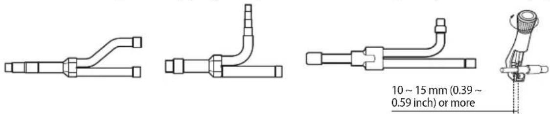
Electrical wiring work
Specification of the circuit breaker and power cable
Single (Heat pump)
| Model MCA MFA | ||
| AM080FXVAHH 18.0 25 | ||
| AM100FXVAHH 21.1 32 | ||
| AM120FXVAHH 25.0 32 | ||
| AM140FXVAHH 25.0 32 | ||
| AM160FXVAHH 32.0 40 | ||
| AM180FXVAHH 39.1 50 | ||
| AM200FXVAHH 42.5 63 | ||
| AM220FXVAHH 44.5 63 | ||
| AM240HXVAHH 55.0 63 | ||
| AM260HXVAHH 58.0 63 |
High Efficiency Single (Heat pump)
| Model MCA MFA | ||
| AM080JXVGHH 18.0 25 | ||
| AM100JXVGHH 21.1 32 | ||
| AM120JXVGHH 25.0 32 | ||
| AM140JXVGHH 25.0 32 | ||
| AM160JXVGHH 32.0 40 | ||
| AM180JXVGHH 39.1 50 | ||
| AM200JXVGHH 42.5 63 |
High Efficiency Single II (Heat pump)
| Model MCA MFA | ||
| AM080KXVGHH 18 25 | ||
| AM100KXVGHH 21.1 32 | ||
| AM120KXVGHH 25 32 | ||
| AM140KXVGHH 25 32 | ||
| AM160KXVGHH 32 40 | ||
| AM180KXVGHH 39.1 50 | ||
| AM200KXVGHH 42.5 63 | ||
| AM220KXVGHH 44.5 63 |
Electrical wiring work
Standard module (Heat pump)
| Model MCA MFA | ||
| AM280HXVAHH1 57.0 63 | ||
| AM300HXVAHH1 64.1 75 | ||
| AM320HXVAHH1 67.5 75 | ||
| AM340HXVAHH1 69.5 80 | ||
| AM360HXVAHH1 69.5 80 | ||
| AM380HXVAHH1 76.5 90 | ||
| AM400HXVAHH1 83.0 100 | ||
| AM420HXVAHH1 87.0 100 | ||
| AM440HXVAHH1 89.0 100 | ||
| AM460HXVAHH1 94.5 125 | ||
| AM480HXVAHH1 94.5 125 | ||
| AM500HXVAHH1 101.5 125 | ||
| AM520HXVAHH1 108.6 125 | ||
| AM540HXVAHH1 112.0 125 | ||
| AM560HXVAHH1 114.0 125 | ||
| AM580HXVAHH1 114.0 125 | ||
| AM600HXVAHH1 121.0 150 | ||
| AM620HXVAHH1 128.1 150 | ||
| AM640HXVAHH1 131.5 150 | ||
| AM660HXVAHH1 133.5 150 | ||
| AM680HXVAHH1 139.0 175 | ||
| AM700HXVAHH1 139.0 175 | ||
| AM720HXVAHH1 146.0 175 | ||
| AM740HXVAHH1 153.1 175 | ||
| AM760HXVAHH1 156.5 175 | ||
| AM780HXVAHH1 158.5 175 | ||
| AM800HXVAHH1 158.5 175 |
Compact module (Heat pump)
| Model MCA MFA | ||
| AM360HXVAHH2 80.0 90 | ||
| AM380HXVAHH2 83.0 100 | ||
| AM460HXVAHH2 100.5 125 | ||
| AM480HXVAHH2 102.5 125 | ||
| AM500HXVAHH2 113.0 125 | ||
| AM520HXVAHH2 116.0 150 | ||
| AM580HXVAHH2 125.5 150 | ||
| AM600HXVAHH2 127.5 150 | ||
| AM620HXVAHH2 138.0 175 | ||
| AM640HXVAHH2 141.0 175 | ||
| AM680HXVAHH2 144.0 175 | ||
| AM700HXVAHH2 147.0 175 | ||
| AM720HXVAHH2 157.5 175 | ||
| AM740HXVAHH2 160.5 200 | ||
| AM760HXVAHH2 171.0 200 | ||
| AM780HXVAHH2 174.0 200 |
High Efficiency module (Heat pump)
| Model MCA MFA | ||
| AM220JXVGHH 46.1 63 | ||
| AM240JXVGHH 50.0 63 | ||
| AM260JXVGHH 50.0 63 | ||
| AM280JXVGHH 57.0 63 | ||
| AM300JXVGHH 64.1 75 | ||
| AM320JXVGHH 67.5 75 | ||
| AM340JXVGHH 67.5 75 | ||
| AM360JXVGHH 74.5 90 | ||
| AM380JXVGHH 81.6 90 | ||
| AM400JXVGHH 85.0 100 | ||
| AM420JXVGHH 88.6 100 | ||
| AM440JXVGHH 92.5 125 | ||
| AM460JXVGHH 92.5 125 | ||
| AM480JXVGHH 99.5 125 | ||
| AM500JXVGHH 106.6 125 | ||
| AM520JXVGHH 110.0 125 | ||
| AM540JXVGHH 110.0 125 | ||
| AM560JXVGHH 117.0 150 | ||
| AM580JXVGHH 124.1 150 | ||
| AM600JXVGHH 127.5 150 | ||
| AM620JXVGHH 131.1 150 | ||
| AM640JXVGHH 135.0 150 | ||
| AM660JXVGHH 135.0 150 | ||
| AM680JXVGHH 142.0 175 | ||
| AM700JXVGHH 149.1 175 | ||
| AM720JXVGHH 152.5 175 | ||
| AM740JXVGHH 152.5 175 | ||
| AM760JXVGHH 159.5 175 | ||
| AM780JXVGHH 166.6 200 | ||
| AM800JXVGHH 170.0 200 |
Electrical wiring work
High Efficiency module II (Heat pump)
| Model MCA MFA | ||
| AM240KXVGHH 50 63 | ||
| AM260KXVGHH 50 63 | ||
| AM280KXVGHH 57 63 | ||
| AM300KXVGHH 64.1 75 | ||
| AM320KXVGHH 67.5 75 | ||
| AM340KXVGHH 69.5 80 | ||
| AM360KXVGHH 69.5 80 | ||
| AM380KXVGHH 76.5 90 | ||
| AM400KXVGHH 85 100 | ||
| AM420KXVGHH 87 100 | ||
| AM440KXVGHH 89 100 | ||
| AM460KXVGHH 94.5 125 | ||
| AM480KXVGHH 94.5 125 | ||
| AM500KXVGHH 101.5 125 | ||
| AM520KXVGHH 108.6 125 | ||
| AM540KXVGHH 112 125 | ||
| AM560KXVGHH 114 125 | ||
| AM580KXVGHH 114 125 | ||
| AM600KXVGHH 121 150 | ||
| AM620KXVGHH 129.5 150 | ||
| AM640KXVGHH 131.5 150 | ||
| AM660KXVGHH 133.5 150 | ||
| AM680KXVGHH 139 175 | ||
| AM700KXVGHH 139 175 | ||
| AM720KXVGHH 146 175 | ||
| AM740KXVGHH 153.1 175 | ||
| AM760KXVGHH 156.5 175 | ||
| AM780KXVGHH 158.5 175 | ||
| AM800KXVGHH 158.5 175 | ||
| AM820KXVGHH 165.5 200 | ||
| AM840KXVGHH 172.6 200 | ||
| AM860KXVGHH 176 200 | ||
| AM880KXVGHH 178 200 |
* When installing outdoor units in module, select the power supply cable according to the sum of outdoor unit capacity. (Refer to the table for each model)
Ex.) AM500FXVAH*
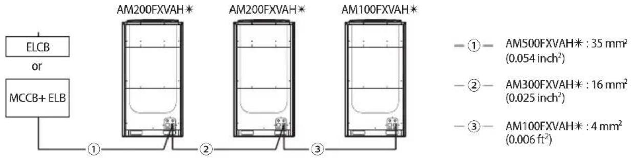

NOTE
- This device is intended for the connection to a power supply system with a maximum permissible system impedance shown in the table (on the left page) at the interface point (power service box) of the user's supply.
- The user must ensure that this device is connected only to a power supply system which fulfills the requirement above. If necessary, the user can ask the public power supply company for the system impedance at the interface point.
- This equipment complies with IEC 61000-3-12 provided that the short-circuit powers is greater than or equal to S_sc (*2) at the interface point between the user's supply and the public system. It is the responsibility of the installer or user of the equipment to ensure, by consultation with the distribution network operator if necessary, that the equipment is connected only to a supply with a short-circuit power S_sc greater than or equal to S_sc (*2). [ S_sc (*2)]
| Model S | sc[MVA] Model S | sc[MVA] | |
| AM080*XV*H* | 3.3 | AM180*XV*H* | 7.6 |
| AM100*XV*H* | 4.5 | AM200*XV*H* | 8.1 |
| AM120*XV*H* | 5.3 | AM220FXVAH* | 8.6 |
| AM140*XV*H* | 5.3 | AM240HXVAH* | 11.7 |
| AM160*XV*H* | 6.8 | AM260HXVAH* | 8.6 |

CAUTION
Caution for electrical work
• You must install ELCB or MCCB + ELB
- ELCB: Earth leakage breaker
- MCCB: Molded case circuit breaker
- ELB: Earth leakage breaker
- Do not operate the outdoor unit before completing the refrigerant pipe work.
- Do not disconnect or change the cable inside the product. It may cause damage to the product.
- Specification of the power cable is selected based on following installation condition; culvert installation/ambient temperature 30 °C (86 °F) / single multi conductor cables. If the condition is different from the ones stated, please consult an electrical installation expert and re-select the power cable.
- If the length of power cable exceed 50 m (164.04 ft), re-select the power cable considering the voltage drop.
- Use a power cable made out of incombustible material for the insulator (inner cover) and the sheath (outer cover).
- Do not use the power cable with the core wire exposed due to insulator damage occurred during removal of the sheath. When the core wire is exposed, it may cause fire.
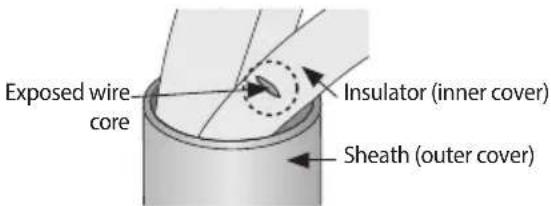
(The example of exposed core wire>
Electrical wiring work
Power and communication cable configuration
▶ Main power and the ground cable must be withdrawn through the knock-out hole on the bottom-right or right side of the cabinet.
▶ Withdraw the communication cable from the designated knock-out hole on the bottom-right side of the front part.
▶ Install the power and communication cable using separate cable protection tube.
▶ Fix a protection tube to the knock-out hole on the outdoor unit by using a CD connector or bushing. Make sure to use insulating bushing.
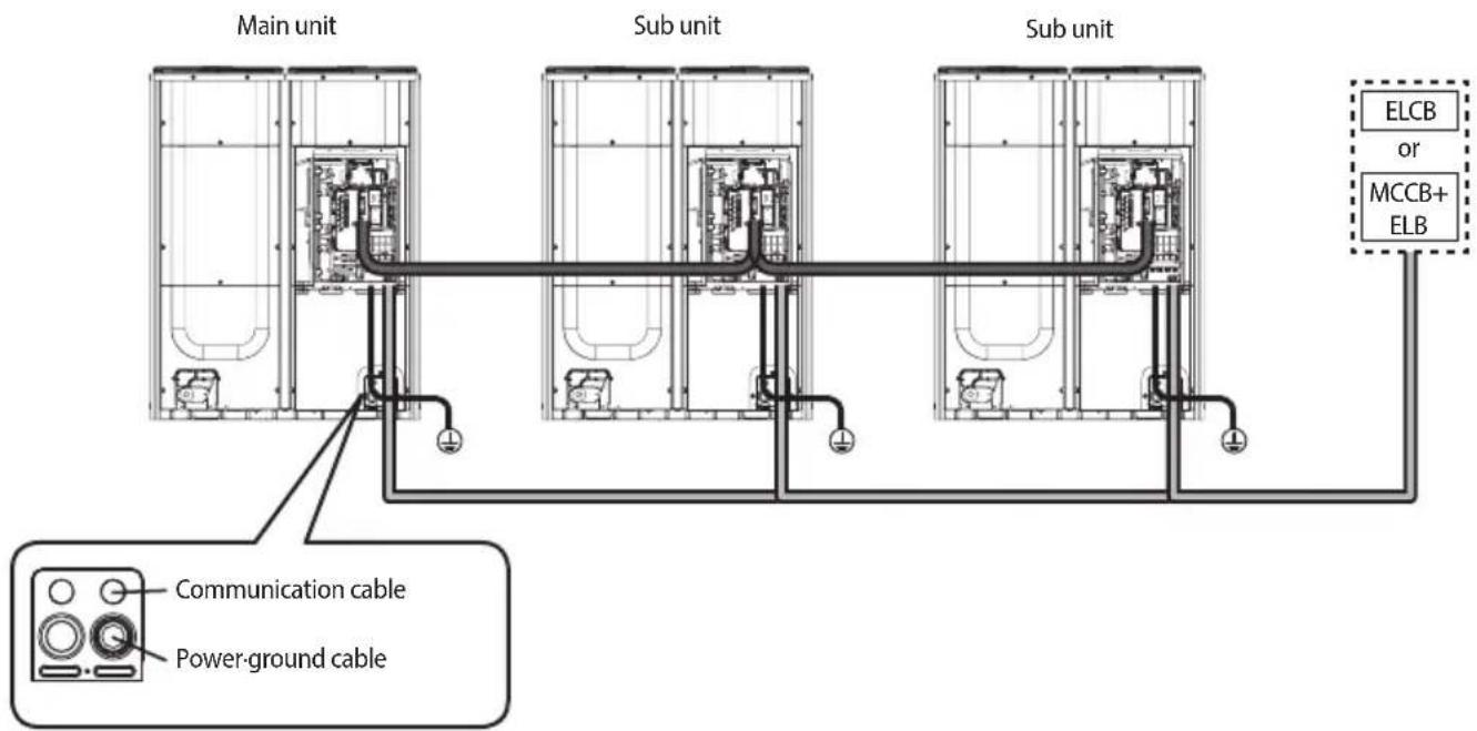

Communication cable between outdoor units Power cable


Protection tube Power/ground cable

| Name Temper grade | Applicable conditions | |
| Flexible PVC conduit PVC | When the protection tube is installed indoor and not exposed to outside, because it is embedded in concrete structure | |
| Class 1 flexible conduit Galvanized steel sheet | When the protection tube is installed indoor but exposed to outside so there are risk of damage to the protection tube | |
| Class 1 PVC coated flexible conduit | Galvanized steel sheet and Soft PVC compound | When the protection tube is installed outdoor and exposed to outside so there are risk of damage to the protection tube and extra waterproof is needed |

Caution for perforating the knock-out hole
- Perforate a knock-out hole by punching it with a hammer.
• After perforating the knock-out hole, apply rust resisting paint around the hole. - When you need to pass the cables through the knock-out hole, remove burrs on the hole and protection the cable with a protection tape or bushing etc.
Caution for installing communication cable
- When you connect the cable, it may sag and pressed by other parts. Therefore cables should be fixed to a clamp highlighted with a box on the illustration.
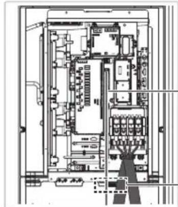
natural_image
Architectural floor plan showing room layouts and equipment layout (no text or labels)Path for arranging external communication cable
Fixing location of the external communication cable
Electrical wiring work
Power wiring diagram
Supplying 3 phase 4 wires (380 V\~)
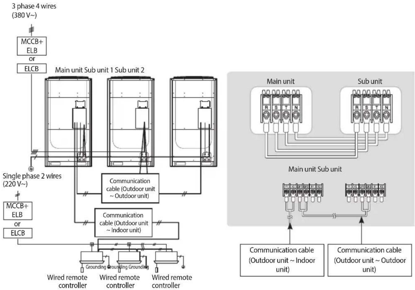
flowchart
graph TD
    A["3 phase 4 wires (380 V~)"] --> B["MCCB+ ELB or ELCB"]
    B --> C["Main unit Sub unit 1 Sub unit 2"]
    C --> D["Single phase 2 wires (220 V~)"]
    D --> E["MCCB+ ELB or ELCB"]
    C --> F["Communication cable (Outdoor unit ~ Outdoor unit)"]
    F --> G["Grounding"]
    F --> H["Wired remote controller"]
    F --> I["Wired remote controller"]
    F --> J["Wired remote controller"]
    C --> K["Communication cable (Outdoor unit ~ Indoor unit)"]
    K --> L["Grounding"]
    K --> M["Wired remote controller"]
    K --> N["Wired remote controller"]
    C --> O["Main unit Sub unit"]
    O --> P["Main unit"]
    O --> Q["Sub unit"]
    P --> R["Main unit Sub unit"]
    Q --> S["Sub unit"]
    R --> T["Communication cable (Outdoor unit ~ Indoor unit)"]
    S --> U["Communication cable (Outdoor unit ~ Outdoor unit)"]
Connect a power cable of the outdoor unit after checking that R-S-T-N (3 phase 4 wire) is properly connected. (If the 380 V power is supplied to the N phase, PCB and other electrical part will be damaged.)
▶ Communication cable between indoor and outdoor units and communication cable between outdoor units has no polarity.
▶ Arrange the cables with a cable tie.
* ELCB and ELB must be installed since there is risk of electric shock or fire when they are not installed.
Selecting solderless ring terminal
▶ Select a solderless ring terminal for a power cable according to the nominal dimensions for cable.
▶ Apply insulation coating to the connection part of the solderless ring terminal and the power cable.
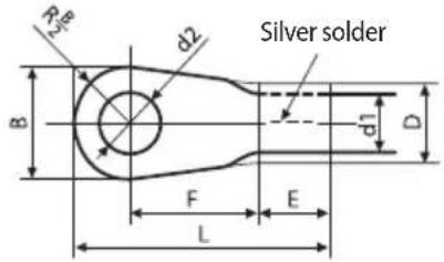
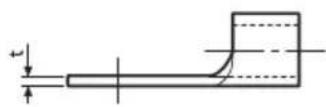
| Nominal dimensions for cable [mm2 (inch2)] | 4/6 (0.006/0.009) | 10 (0.01) 16 | (0.02) 25 (0.03) 35 (0.05) 50 (0.07) 70 (0.10) | ||||||||
| Nominal dimensions for screw [mm (inch)] | 4 (3/8) 8 | (3/16) 8 (3/16) 8 (3/16) 8 (3/16) 8 (3/16) 8 (3/16) 8 (3/16) 8 (3/16) 8 (3/16) 8 (3/16) 8 (3/16) 8 (3/16) 8 (3/16) 8 (3/11) | |||||||||
| B | Standard dimension [mm (inch)] | 9.5 (3/8) | 15 (9/16) | 15 (9/16) 16 | (10/16) 12 (1/2) | 16.5 (10/16) | 16 (10/16) | 22 (7/8) | 22 (7/8) 24 (1) | ||
| Allowance [mm (inch)] | ±0.2 (±0.007) | ±0.2 (±0.007) | ±0.2 (±0.007) | ±0.3 (±0.011) ±0.3 (±0.011) | ±0.3 (±0.011) | ±0.4 (±0.015) | |||||
| D | Standard dimension [mm (inch)] | 5.6 (1/4) | 7.1 (1/4) | 9 (3/8) | 11.5 (7/16) | 13.3 (1/2) | 13.5 (1/2) | 17.5 (1/2) | |||
| Allowance [mm (inch)] | +0.3 (+0.011) -0.2 (-0.007) | +0.3 (+0.011) -0.2 (-0.007) | +0.3 (+0.011) -0.2 (-0.007) | +0.5 (+0.019) -0.2 (-0.007) | +0.5 (+0.019) -0.2 (-0.007) | +0.5 (+0.019) -0.2 (-0.007) | +0.5 (+0.019) -0.4 (-0.015) | ||||
| d1 | Standard dimension [mm (inch)] | 3.4 (1/8) | 4.5 (3/16) | 5.8 (1/4) | 7.7 (5/16) | 9.4 (3/8) | 11.4 (7/16) | 13.3 (1/2) | |||
| Allowance [mm (inch)] | ±0.2 (±0.007) | ±0.2 (±0.007) | ±0.2 (±0.007) | ±0.2 (±0.007) | ±0.2 (±0.007) | ±0.3 (±0.011) | ±0.4 (±0.015) | ||||
| E Min. [mm (inch)] | 6 (1/4) | 7.9 (5/16) | 9.5 (5/16) | 11 (3/8) | 12.5 (1/2) | 17.5 (11/16) | 18.5 (3/4) | ||||
| F Min. [mm (inch)] | 5 (3/16) | 9 (3/8) | 9 (3/8) | 13 (1/2) | 15 (5/8) | 13 (1/2) | 13 (1/2) | 13 (1/2) | 14 (9/16) | 20 (3/4) | |
| L | Max. [mm (inch)] | 20 (3/4) | 28.5 (1-1/8) | 30 (1-3/16) | 33 (1-5/16) | 34 (1-3/8) | 38 (1-1/2) | 43 (1-11/16) | 50 (2) | 51 (2) | |
| d2 | Standard dimension [mm (inch)] | 4.3 (3/16) | 8.4 (1-3/16) | 8.4 (1-3/16) | 8.4 (1-3/16) | 8.4 (1-3/16) | 8.4 (1-3/16) | 8.4 (1-3/16) | 8.4 (1-3/16) | 8.4 (1-3/16) | 8.4 (1-3/15) |
| Allowance [mm (inch)] | +0.2 (+0.007) 0 (0) | +0.4 (+0.015) 0 (0) | +0.4 (+0.015) 0 (0) | +0.4 (+0.015) 0 (0) | +0.4 (+0.015) 0 (0) | +0.4 (+0.015) 0 (0) | +0.4 (+0.015) 0 (0) | +0.4 (+0.015) 0 (0) | |||
| t | Min. [mm (inch)] | 0.9 (0.03) | 1.15 (0.04) | 1.45 (0.05) | 1.7 (0.06) | 1.8 (0.07) | 1.8 (0.07) | 2.0 (0.078) | |||
Electrical wiring work
Connecting the power terminal
▶ Connect the cables to the terminal board with solderless ring terminals.
▶ Properly connect the cables by using certified and rated cables and make sure to fix them properly so that external force is not applied to the terminal.
▶ Use a driver and wrench that can apply the rated torque when tightening the screws on the terminal board.
▶ Tighten the terminal screws by complying rated torque value. If the terminal is loose, fire can occur due to arc heat generation and if the terminal is too tight, terminal board could get damaged.
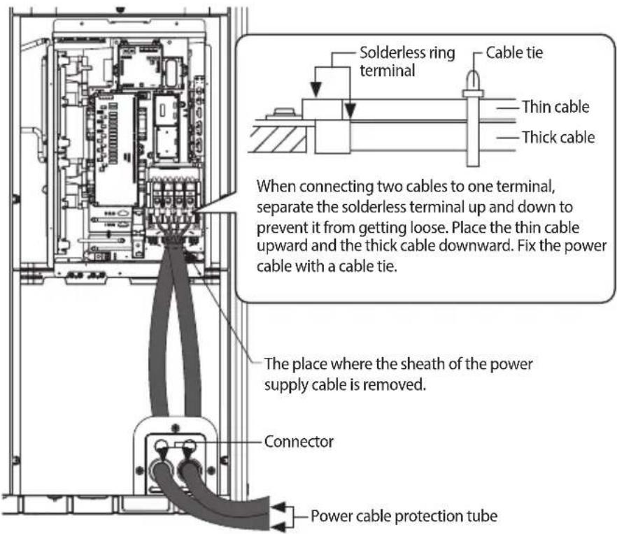

- When removing the outer sheath of the power supply cable, be careful not to scratch the inner sheath of the cable.
- Make sure that more than 20 mm (0.79 inch) of the outer sheath of the indoor unit power and communication cable are inside the electrical component box.
• Install the communication cable separately from power cable and other communication cables.
| Screw | Tightening torque for terminal | Remarks | |
| N·m lbf·ft | |||
| M4 1.2~1.5 | 0.9~1.1 Single phase (220 V) power cable | ||
| M8 5.5~7.3 | 4.1~5.4 3 phase (380 V) power cable | ||
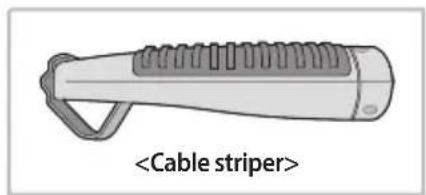
natural_image
Illustration of a cable stripper tool with threaded body and handle (no text or symbols on the diagram itself)-
Adjust the blade position by coin. (Controller is at the bottom side of the tool.) Fix the blade position according to the outer sheath thickness of the power cable.
-
Fix the power cable and tool by using the hook at the top side of the tool.
-
Cut out the outer sheath of the power cable by revolving the tool in the direction of the arrow, two or three times.
-
At this situation, cut out the outer sheath of the power cable by moving the tool toward the direction of the arrow.
-
Slightly bend the wire and pull out the cut part of the outer sheath.
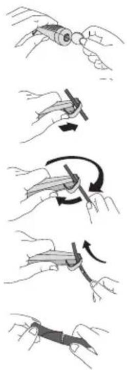
natural_image
Illustration of a hand holding a tool with multiple steps of folding or cutting (no text or symbols)Electrical wiring work
Fixing the power cable
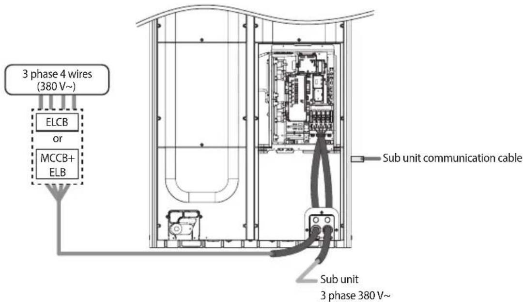

- Do not let the power cable come into contact with the pipes inside the outdoor unit. If the power supply cable touches the pipes, the vibration of the compressor is transferred to the pipes and can damage the power supply cables or pipes, creating the danger of fire or explosion.
- Make sure that the place where the sheath of power supply cable is removed is inside the power supply box. If it is impossible, you should connect the protection tube for power cable to the power supply box.
• After arranging the power cable into the power supply box, tighten the cover.
Connect the ring terminal of 3 phase cable
- Cut the power cable to an appropriate length and connect it with the solderless terminal.
- After connecting the power cable to the terminal as seen in the illustration, fix it with cable tie.
- Fix the housing, which has an insulator, to the terminal board.
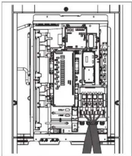
natural_image
Architectural floor plan of an electronic device showing internal components and wiring (no text or labels)Fixing the ground cable
Connect the ground cable to the grounding hole inside the power supply box.
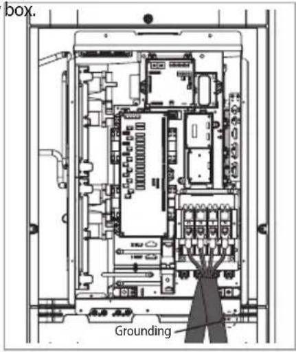
Withdrawing the power cable
▶ Withdrawing from the front side
- Connect the power cable protection tube into the power supply box as shown picture.
- Be sure that the power supply cable is not damaged by burr on the knock-out hole.
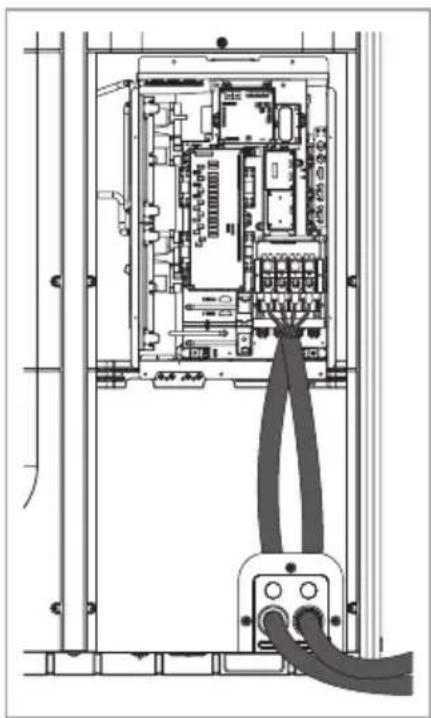
natural_image
Technical line drawing of an electrical enclosure with visible wiring and components (no text or labels)Electrical wiring work
Installing the Solution device
When the number of indoor units installed with the outdoor unit is 16 or less
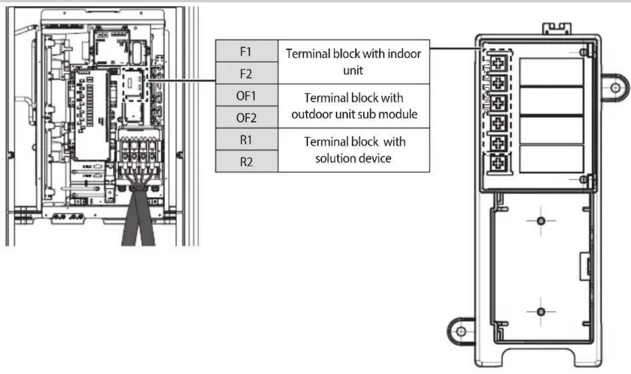
Grounding work
Grounding must be done by a qualified installer for your safety.
Grounding the power cable
The standard of grounding may vary according to the rated voltage and installation place of the air conditioner.
▶ Ground the power cable according to the following table.
| Installation place\Power condition | Voltage to ground is lower than 150V Voltage to ground is over 150V | |
| High humidity | Must perform the grounding work 3. Note 1)(Including the case where earth leakage breaker is installed) | |
| Average humidity Perform grounding work 3. Note 1) | Must perform the grounding work 3. Note 1)(Including the case where earth leakage breaker is installed) | |
| Low humidity | Perform grounding work 3, if possible, for your safety. Note 2) | |
Note 1) About grounding work 3.
• Grounding work must be done by an expert (with qualification).
- Check if the grounding resistance is lower than 100 Ω. When installing a earth leakage breaker (that can cut the electric circuit within 0.5 second in case of a short circuit), allowable grounding resistance should be 30\~500 Ω.
Note 2) Grounding at dry place
- The grounding resistance should be lower than 100 . Even in worst case, grounding resistance should be lower than 250 .
Performing the grounding work
▶ Use a rated grounding cable by referring to the specification of the electric cable for the outdoor unit.
* When using the exclusive grounding terminal (When the grounding terminal is already built on the house)
* When using grounding of the switch board
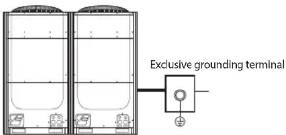
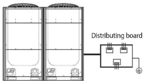
Air tightness test and vacuum drying
Air tightness test
▶ Use tools for R-410A to prevent the inflow of foreign substances and resist against the internal pressure.
▶ Do not remove the core of filling port.
▶ Use Nitrogen gas for air tightness test as shown in the illustration.
H/P
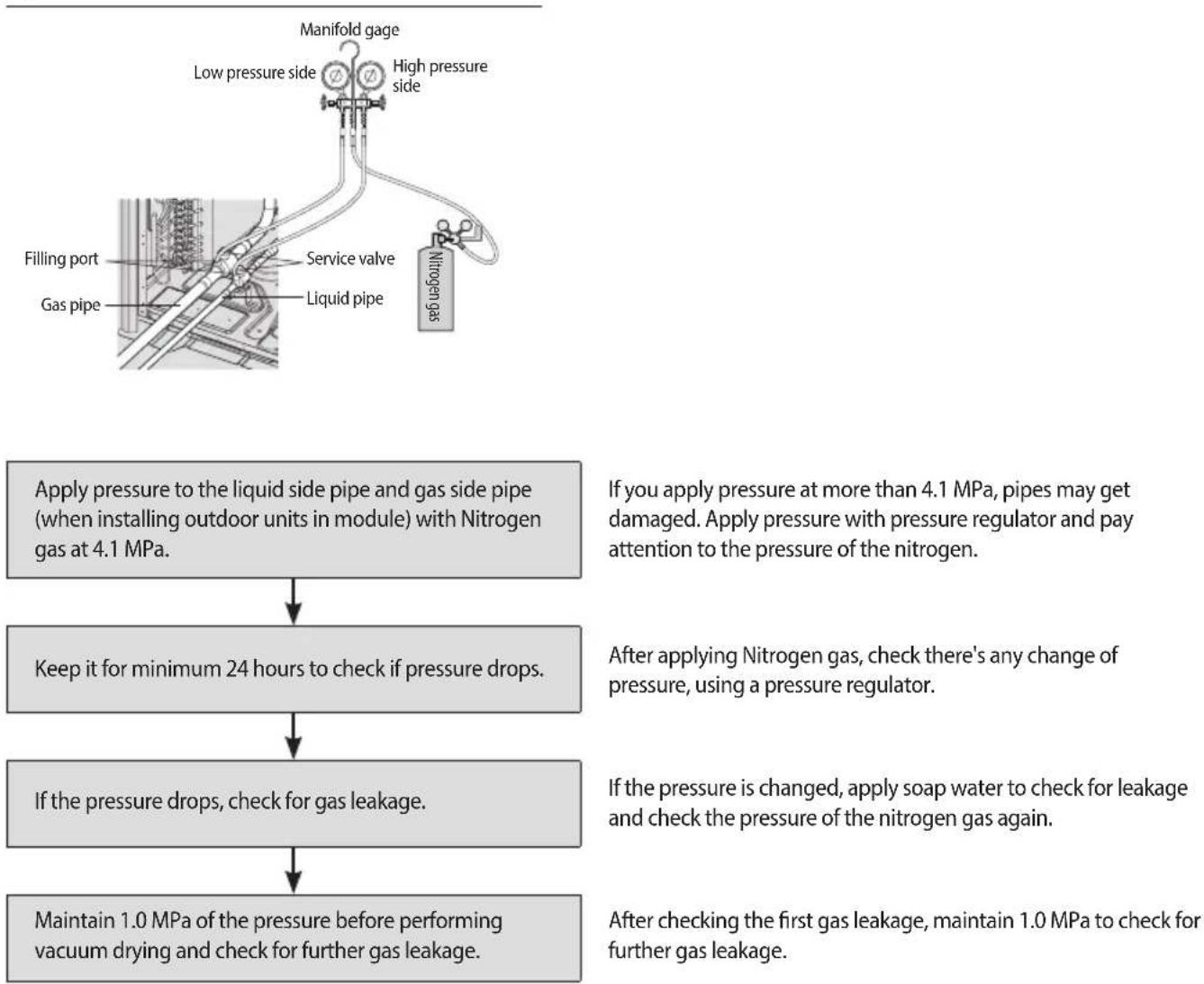
flowchart
graph TD
    A["Manifold gage"] --> B["Low pressure side"]
    A --> C["High pressure side"]
    B --> D["Filling port"]
    B --> E["Service valve"]
    B --> F["Liquid pipe"]
    C --> G["Nitrogen gas"]
    D --> H["Apply pressure to the liquid side pipe and gas side pipe (when installing outdoor units in module) with Nitrogen gas at 4.1 MPa."]
    E --> H
    F --> H
    H --> I["Keep it for minimum 24 hours to check if pressure drops."]
    I --> J["If the pressure drops, check for gas leakage."]
    J --> K["Maintain 1.0 MPa of the pressure before performing vacuum drying and check for further gas leakage."]
    K --> L["After applying Nitrogen gas, check there's any change of pressure, using a pressure regulator."]
    L --> M["If the pressure is changed, apply soap water to check for leakage and check the pressure of the nitrogen gas again."]
    M --> N["After checking the first gas leakage, maintain 1.0 MPa to check for further gas leakage."]

• Perform a Nitrogen gas leak test with the service valve of the outdoor unit closed.
- When charging the nitrogen gas, charge it from the both (high-low pressure) sides.
- If the pipe is filled in a short time with a highly excessive pressure of Nitrogen gas, the pipes may get damaged. Make sure to use a regulator to prevent the high pressure Nitrogen gas, over 4.1 MPa, from entering into the pipe.
Vacuum drying pipes and indoor units
▶ Use tools for R-410A to prevent the inflow of foreign substances and resist against the internal pressure.
▶ Use vacuum pump that allows vacuuming under -100.7 kPa (5 Torr).
▶ Use the vacuum pump with the check valve to prevent pump oil from flowing backward while the vacuum pump is stopped.
▶ Completely close the liquid-gas side service valve of the outdoor unit.
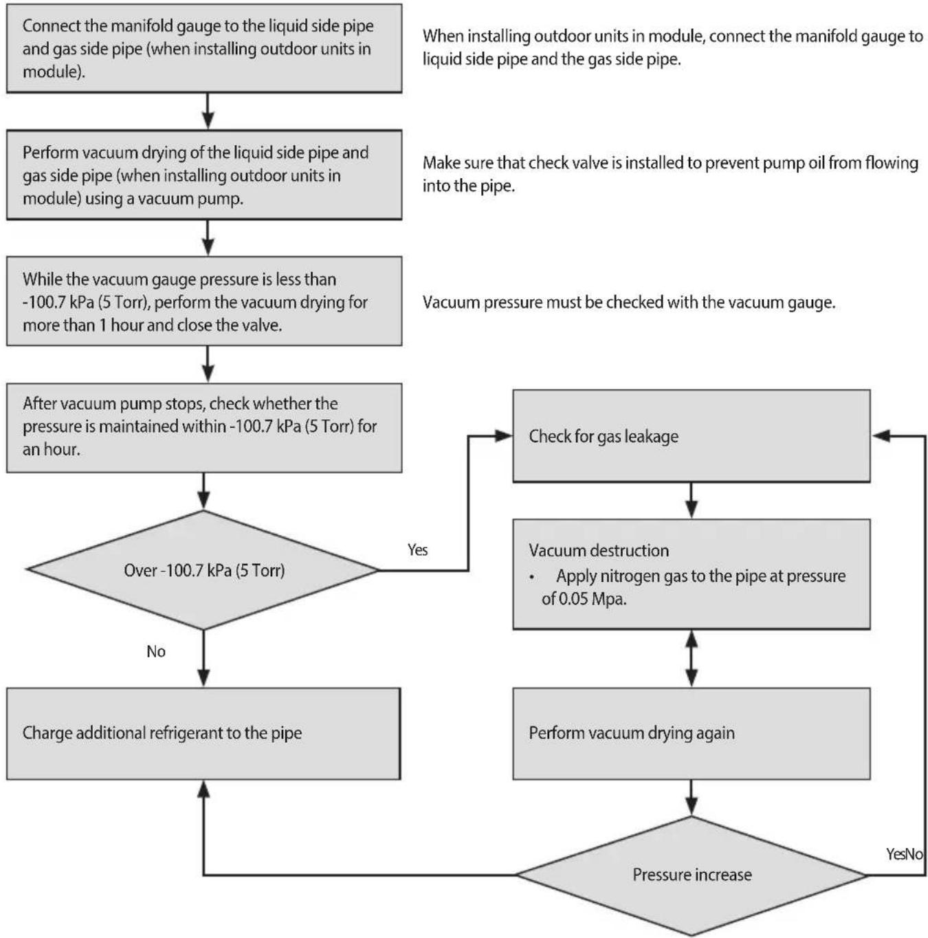
flowchart
graph TD
    A["Connect the manifold gauge to the liquid side pipe and gas side pipe (when installing outdoor units in module)."] --> B["Perform vacuum drying of the liquid side pipe and gas side pipe (when installing outdoor units in module) using a vacuum pump."]
    B --> C["While the vacuum gauge pressure is less than -100.7 kPa (5 Torr), perform the vacuum drying for more than 1 hour and close the valve."]
    C --> D["After vacuum pump stops, check whether the pressure is maintained within -100.7 kPa (5 Torr) for an hour."]
    D --> E{Over -100.7 kPa (5 Torr)}
    E -->|Yes| F["Check for gas leakage"]
    E -->|No| G["Charge additional refrigerant to the pipe"]
    F --> H["Vacuum destruction<br>• Apply nitrogen gas to the pipe at pressure of 0.05 Mpa."]
    H --> I["Perform vacuum drying again"]
    I --> J{Pressure increase}
    J -->|Yes| K["Check for gas leakage"]
    J -->|No| L["Charge additional refrigerant to the pipe"]
    K --> M["Check for gas leakage"]
    L --> N["Check for gas leakage"]
    M --> O["Check for gas leakage"]
    N --> P["Check for gas leakage"]
* If the pressure rises in an hour, either water is remaining inside the pipe or there is a leakage.
* When the ambient temperature of vacuuming pipe is low (less than 0 °C (32 °F)), moisture might remain within the pipe. Therefore, pay special attention to the pipe sealing in the winter.
Pipe insulation
Insulating the refrigerant pipes and branch joints
▶ Check for gas leakage before completing (the hose and pipe insulation) and if there is no sign of leakage, make sure to insulate the pipes and hoses.
▶ Use EPDM material insulator that meets the following conditions.
| Test item Unit Standard | ||
| Density g/cm | ^3 | 0.048~0.096 |
| Dimensional change rate by heat % Below -5 | ||
| Absorption rate g/cm | ^3 | Below 0.005 |
| Thermal conduction rate W/m·K Below 0.037 | ||
| Moisture transpiration factor ng/(m | ^2 ·s·Pa) Below 15 | |
| Moisture transpiration grade g/(m | ^2 ·24h) Below 15 | |
| Formaldehyde dispersion mg/L | There should be none | |
| Oxygen rate | % | Over 25 |
Selecting the refrigerant pipe insulator
▶ Insulate the gas pipe and liquid pipe by referring to the thickness of insulator for each pipe size.
The standard condition is; temperature at 30 °C (86 °F), humidity less than 85%. If case if the humidity is higher, you must increase the size by one grade as stated in below table.
| Pipe | Outer diameter | Insulator (Cooling, Heating) | Remarks | ||||
| General[30°C (86°F), 85%] | High humidity[30°C (86°F), over 85%] | ||||||
| EPDM, NBR | |||||||
| mm | inch | mm | inch | mm | inch | ||
| Liquid pipe | 6.35~9.52 | 1/4~3/8 | 9 | 3/8 | 9 | 3/8 | Heating resisting temperature over 120°C(248°F) |
| 12.7~50.8 | 1/2~2 | 13 | 1/2 | 13 | 1/2 | ||
| Gas pipe | 6.35 | 1/4 | 13 | 1/2 | 19 | 3/4 | |
| 9.52~25.4 | 3/8~1 | 19 | 3/4 | 25 | 1 | ||
| 28.58~44.45 | 1 1/8~1 3/4 | 19 | 3/4 | 32 | 1 1/4 | ||
| 50.8 | 2 | 25 | 1 | 38 | 1 1/2 | ||
* When installing insulation in places and conditions below, use the same insulation that is used for high humidity conditions.
- High humidity places such as shoreline, hot spring, near lake or river, and ridge (when the part of the building is covered by earth and sand.)
- Restaurant ceiling, sauna, swimming pool etc.
- The ceiling frequently exposed to moisture and cooling is not covered. (e.g. The pipe installed at a corridor of a dormitory and studio or near an exit that opens and closes frequently.")
- The place where the pipe is installed is highly humid due to the lack of ventilation system.
Insulate the refrigerant pipe
▶ Make sure to insulate the refrigerant pipe, branch joint, distribution header, and the connection part of the pipes.
If you insulate the pipes, condensed water will not fall from the pipes.
▶ Check if there are any cracks on the insulation at the bent part of the pipe.
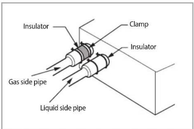
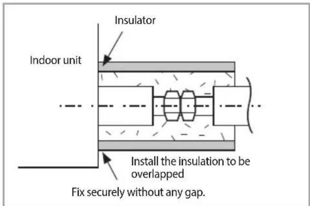
Insulating pipes Insulating pipes connected behind the EEV kit
- The insulation of the gas and liquid pipes can be in contact with each other but they should not press excessively against each other.
- When the gas side and liquid side pipes are contacting each other, increase the thickness of the insulation by one grade.
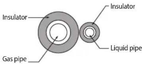
- When installing the gas side and liquid side pipes, leave at least 10 mm (3/8") of space.
- When the gas side and liquid side pipes are contacting each other, increase the thickness of the insulation by one grade.
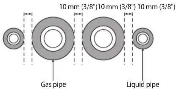

Install the insulation without any gaps or cracks and use adhesive on the connection part of it to prevent moisture from entering.
- Bind the refrigerant pipe with insulation tape if it is exposed to outside sunlight. (When binding the pipe with finishing tape, be careful not to reduce the thickness of the insulation.)
• Install the refrigerant pipe respecting that the insulation does not get thinner on the bent part or hanger of pipe. - When the thickness of insulation is reduced, reinforce the reduced thickness with additional insulation.
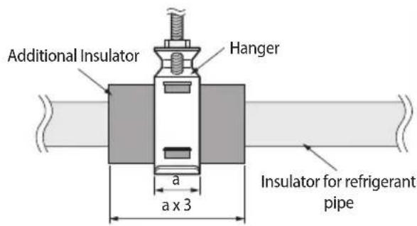
Pipe insulation
Insulate the distribution header
▶ Fix the distribution header with a cable tie and cover the connected part.
▶ Insulate the distribution header and the welded part and wrap the connected part with an adhesive insulation tape to prevent dew formation.
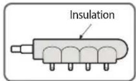
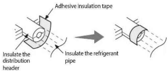
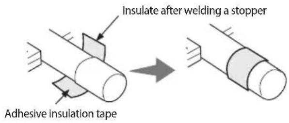
▶ Fix the distribution header with a hanger after insulating it.
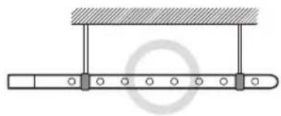
natural_image
Pure mechanical assembly diagram showing a beam supported by two rods with circular holes, no text or symbols present.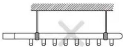
natural_image
Pure mechanical assembly diagram showing a beam supported by rods with no text or symbolsInsulating the branch joint
▶ Tightly attach the insulator, provided with the branch joint, to the separately purchased insulator. Wrap the connected part with an insulator (separately purchased item) that has thickness of at least 10 mm (0.39 inch).
▶ Use an insulator that resist heat up to 120 °C (248 °F). Wrap the branch joint with an insulation that has thickness of at least 10 mm (0.39 inch).
Pipe insulator
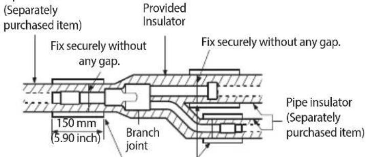
Thickness of the insulator (Separately purchased item) should be thicker than 10 mm (0.39 inch).
Insulation tape (Separately purchased item)
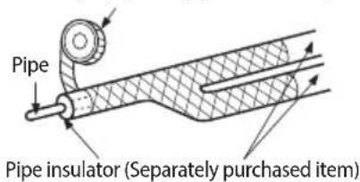
* Attach the adhesive insulation tape to the pipe, as shown in the picture, after insulating the pipe.
Insulating the pipe located inside of the outdoor unit
▶ With a pipe insulator, insulate the pipe up to whole service valve located inside of the outdoor unit.
▶ Seal the gap between the outdoor unit pipe and the insulator. Rainwater and dewdrops may soak through the gap between the pipe and the insulation of the outdoor unit installed on the outside.
Separate the cover of the pipe and close it after insulation work. Only remove a knock-out hole cover where the pipe will be installed. If the knock-out hole is open unnecessarily, it must be closed. If not, small animals such as squirrels and rats may get into the unit through the hole and the unit may be damaged.
H/P
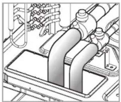
natural_image
Technical line drawing of a mechanical assembly with pipes and components (no visible text or symbols)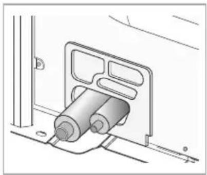
natural_image
Technical line drawing of a mechanical assembly with cylindrical components and mounting brackets (no text or symbols)Charging additional refrigerant
▶ R-410A refrigerant is blended refrigerant. Add refrigerant in liquid form only. (Make sure to use the refrigerant bomb in upright position)
▶ Measure the quantity of the refrigerant according to the length of the liquid side pipe. Add fixed quantity of the refrigerant using a scale.
Single installation
▶ Open the manifold gauge valve connected to the liquid side service valve and add the liquid refrigerant.
▶ If you cannot add the whole quantity of the refrigerant while the outdoor unit is stopped, open the gas side and liquid side service valve. Then, add remaining refrigerant by pressing the refrigerant adding button of the outdoor PCB.
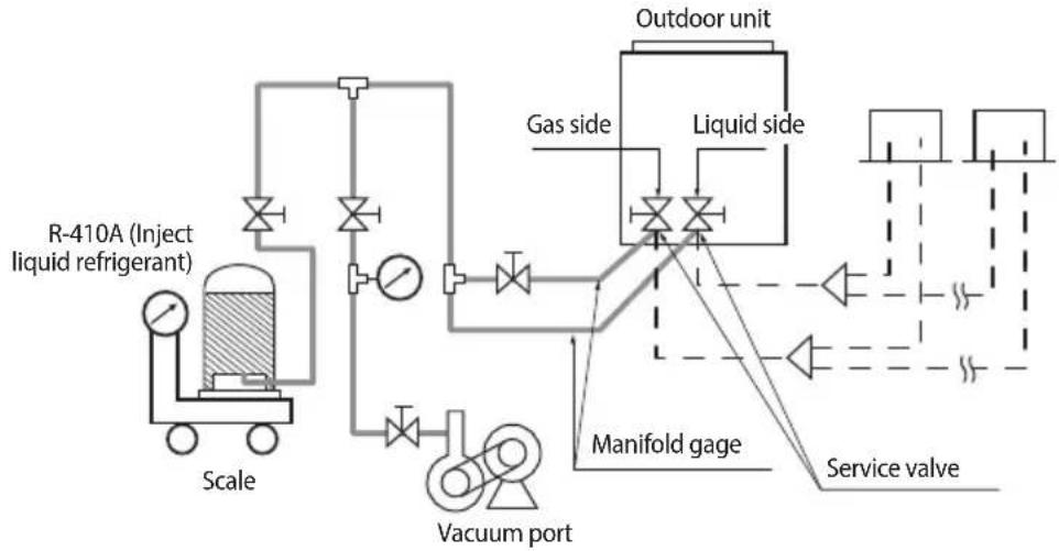
flowchart
graph TD
    A["R-410A (Inject liquid refrigerant)"] --> B["Scale"]
    B --> C["Vacuum port"]
    C --> D["Manifold gage"]
    D --> E["Service valve"]
    D --> F["Liquid side"]
    F --> G["Outdoor unit"]
    G --> H["Gas side"]
    H --> I["Valve with inlet/outlet"]
Module installation
▶ Open the manifold gauge valve connected to the liquid side service valve and add the liquid refrigerant.
If you cannot add the whole quantity of the refrigerant while the outdoor unit is stopped, open the gas side and liquid side service valve. Then, add remaining refrigerant by pressing the refrigerant adding button of the outdoor PCB.
If you use the refrigerant charging function from the PCB, outdoor unit will operate and charge the refrigerant. At this time, you must use gas side manifold gauge for cooling operation and use charging port for heating at the manifold gauge for heating operation.
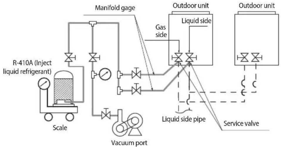
flowchart
graph TD
    A["R-410A (Inject liquid refrigerant)"] --> B["Scale"]
    B --> C["Manifold gage"]
    C --> D["Vacuum port"]
    D --> E["Liquid side pipe"]
    E --> F["Outdoor unit"]
    F --> G["Service valve"]
    G --> H["Liquid side"]
    H --> I["Outdoor unit"]
    I --> J["Gas side"]
    J --> K["Outdoor unit"]

- Open the gas side and liquid side service valve completely after charging the refrigerant. (If you operate the air conditioner with the service valve closed, the important parts may be damaged.)
• Put on safety equipment when charging refrigerant. - Do not charge the refrigerant when you adjust or control other product such as indoor units or EEV kits.
- If you charge the refrigerant with the front cabinet open, be very careful with the fan on the top of the product to prevent personal injury.
- When the ambient temperature is low in winter time, do not heat the refrigerant container to speed up the charging process. There is risk of explosion.
- Beware for possibility of refrigerant leakage when you connect the manifold gauge to the charging port for heating.
- Close the valve of the refrigerant container immediately after charging the refrigerant. If not, there might be a change in entire amount of refrigerant.
Using service valve for gas
▶ After charging the refrigerant, close all caps as shown in the illustration.
▶ Tightening torque for the cap of refrigerant charging port 10\~12 N·m (7.4 \~ 8.9 lbf·ft)
▶ Tightening torque for the cap of control part 20\~25 N·m (14.8 \~ 18.4 lbf·ft)
▶ Opening/closing torque for the valve
- Over ∅19.05 mm (∅3/4): 10 N·m (7.4 lbf·ft)
Cap for the control part
Cap for the refrigerant charging port
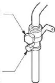
natural_image
Technical line drawing of a mechanical valve assembly (no text or symbols)Basic segment display
| Step Display content | Display | ||||
| At initial power input Checking | segment display | SEG 1 SEG | 2 SEG 3 SEG 4 | ||
| “8” “8” “8” “8” | |||||
| While setting communication between indoor and outdoor unit (Addressing) | Number of connected indoor units | SEG 1 SEG | 2 SEG 3 SEG 4 | ||
| “A” “d” | Number of communicated units* Refer to "View Mode" for communication address | ||||
| After communication setting (usual occasion) | Transmit/Reception address | SEG 1 SEG | 2 SEG 3 SEG 4 | ||
| I/U:“A”MCU:“C” | I/U:“0”MCU:“1” | Reception address (in decimal number) | |||
* I/U: Indoor unit
Setting outdoor unit option switch and key function
Setting outdoor unit option switches: A TYPE
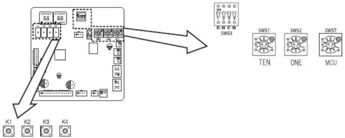
flowchart
graph TD
    A["Switch K1"] --> B["Component 88"]
    C["Switch K2"] --> D["Component 88"]
    E["Switch K3"] --> F["Component 88"]
    G["Switch K4"] --> H["Component 88"]
    I["Switch SW53"] --> J["SW51 TEN"]
    I --> K["SW52 ONE"]
    I --> L["SW57 MCU"]
| Switch Setting Function | Remarks | |||
| SW51 / SW52 | Setting total number of installed indoor unitSW51: Tens digit, SW52: Units digit | Setting can be done from the main outdoor unit only (sub unit: setting is unnecessary)Ex) When 12 indoor units are installed→ SW51: 1, SW52: 2 | ||
| SW53 | K6 | On | Enable maximum capacity restriction for cooling operation | Restrict excessive capacity increase when operating indoor units with small capacity |
| Off | Disable maximum capacity restriction for cooling operation | - | ||
| K7 K8 | Selecting outdoor unit address | |||
| On | On | Outdoor unit address: No. 1 | Main unit | |
| On | Off | Outdoor unit address: No. 2 | Sub unit 1 | |
| Off | On | Outdoor unit address: No. 3 | Sub unit 2 | |
| Off | Off | Outdoor unit address: No. 4 | Sub unit 3 | |
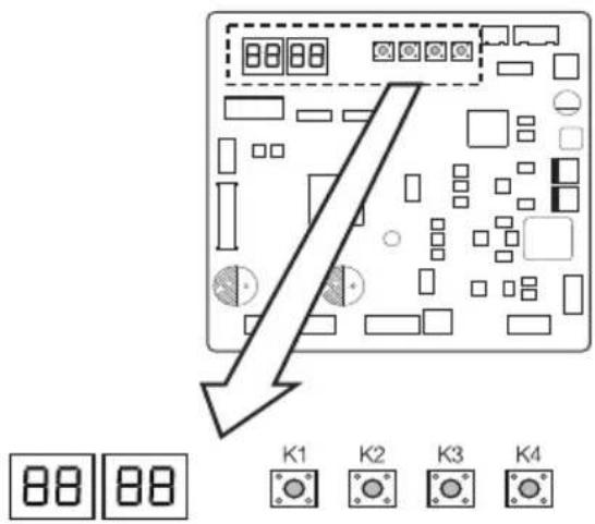
▶ Setting outdoor install option
| Step B | Button Display Description Note | |||
| Outdoor unit address | ||||
| Step1 | Outdoor unit display | od nd | Setting required - | |
| Step2 | Press (K1+K2) for 2 seconds | od 00 | Unit address for module combination | 00: Main unit |
| K4 x 1 time | od 01 | 01: Sub1 unit | ||
| K4 x 2 times | od 02 | 02: Sub2 unit | ||
| K4 x 3 times | od 03 | 03: Sub3 unit | ||
| Step3 | If it is main unit, go to step4. Otherwise, press K2 button for 2 seconds to save & exit (system will be reset) | |||
| Quantity of indoor units | ||||
| Step4 | Press K1 | -à 00 | Ready to set - | |
| Step5 | K2 x n times | -à X 0 | Tens digit (0 ~ 6) | Ex) 03: 3 units64: 64 units |
| K4 x n times | -à 0X | Ones digit (0 ~ 9) | ||
| *K4: Press for 2 seconds - automatic detection of indoor units' quantity | ||||
| Step6 | If it is heat recovery model, go to step 7. Otherwise, press K2 button for 2 seconds to save & exit (system will be reset) | |||
| Quantity of MCUs * Heat recovery model only | ||||
| Step7 | Press K1 | nC 00 | Ready to set - | |
| Step8 | K2 x n times | nC X 0 | Tens digit (0 ~ 1) | Ex) 03: 3 units16: 16 units |
| K4 x n times | nC 0X | Ones digit (0 ~ 9) | ||
| *K4: Press for 2 seconds - automatic detection of MCUs' quantity | ||||
| Step9 | K2: long | Ad 00 | Save Restart | |
| *Press K1 for 2 seconds to exit without save regardless of setting step. | ||||
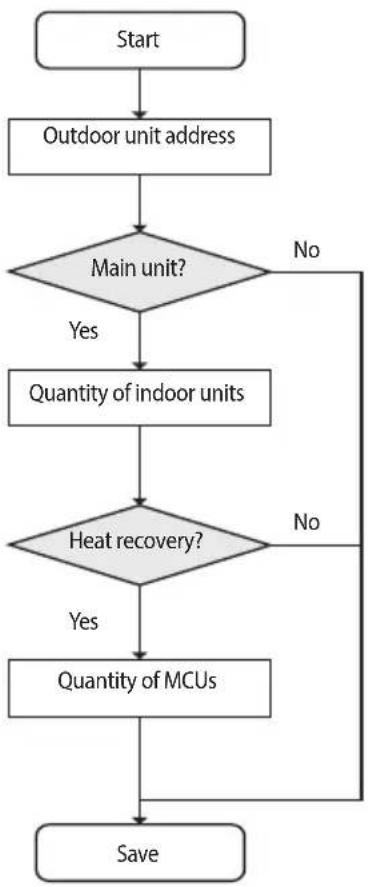
flowchart
graph TD
    A["Start"] --> B["Outdoor unit address"]
    B --> C{Main unit?}
    C -->|Yes| D["Quantity of indoor units"]
    C -->|No| E["Save"]
    D --> F{Heat recovery?}
    F -->|Yes| G["Quantity of MCUs"]
    F -->|No| E
Setting outdoor unit option switch and key function
Installing and setting the option with tact switch and explanation of the functions
Setting the option
- Press and hold K2 to enter the option setting. (Only available when the operation is stopped)
- If you enter the option setting, display will show the following. (If you have set the 'Emergency operation for compressor malfunction', 1 or 2 will be displayed on Seg 4.)
- Seg 1 and Seg 2 will display the number for selected option.
- Seg 3 and Seg 4 will display the number for set value of the selected option.
- If you have entered option setting, you can shortly press the K1 switch to adjust the value of the Seg 1, Seg 2 and select the desired option. (Refer to pages 68\~71 for the Seg number of the function for each option)
Example)


- If you have selected desired option, you can shortly press the K2 switch to adjust the value of the Seg 3, Seg 4 and change the function for the selected option. (Refer to pages 68\~71 for the Seg number of the function for each option)
Example)

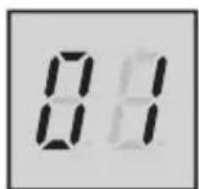
- After selecting the function for options, press and hold the K2 switch for 2 seconds. Edited value of the option will be saved when entire segments blinks and tracking mode begins.

CAUTION
- Edited option will not be saved if you do not end the option setting as explained in above instruction.
* While you are setting the option, you may press and hold the K1 button to reset the value to previous setting.
* If you want to restore the setting to factory default, press and hold the K4 button while you are in the option setting mode.
- If you press and hold the K4 button, setting will be restored to factory default but it doesn't mean that restored setting is saved. Press and hold the K2 button. When the segments shows that tracking mode is in progress, setting will be saved.
| Optional item | Input unit | SEG1 | SEG2 | SEG3 | SEG4 | Function of the option | Remarks |
| Emergency operation for compressor malfunction | Individual 0 | 0 | 0 0 | Disabled | (Factory default) | E560 will occur when all the compressors are set as malfunction state. | |
| 0 | 1 | Set compressor 1 as malfunction state | |||||
| 0 | 2 | Set compressor 2 as malfunction state | |||||
| Cooling capacity correction | Main 0 1 | 0 | 0 | 7-9 (Factory default in case of A type PBA) | Targeted evaporation temperature [°C]. (When low temperature value is set, discharged air temperature of the indoor unit will decrease) | ||
| 0 | 1 | 5-7 (Factory default in case of B type PBA) | |||||
| 0 2 9 | -11 | ||||||
| 0 3 1 | 0-12 | ||||||
| 0 4 1 | 1-13 | ||||||
| 0 5 1 | 2-14 | ||||||
| 0 6 1 | 3-15 | ||||||
| Capcity correction for heating | Main 0 2 | 0 0 3 | 0 (Factory default) | Targeted high pressure [MPa]. (When low pressure value is set, discharged air temperature of the indoor unit will decrease) | |||
| 0 1 2 | 5 | ||||||
| 0 2 2 | 6 | ||||||
| 0 3 2 | 7 | ||||||
| 0 4 2 | 8 | ||||||
| 0 5 2 | 9 | ||||||
| 0 6 3 | 1 | ||||||
| 0 7 3 | 2 | ||||||
| 0 8 3 | 3 | ||||||
| Current restriction rate | Individual 0 | 3 | 0 0 1 | 100% (Factory default) | When restriction option is set, cooling and heating performance may decrease. | ||
| 0 1 9 | 5 % | ||||||
| 0 2 9 | 90 % | ||||||
| 0 3 8 | 5 % | ||||||
| 0 4 8 | 0 % | ||||||
| 0 5 7 | 5 % | ||||||
| 0 6 7 | 0 % | ||||||
| 0 7 6 | 5 % | ||||||
| 0 8 6 | 0 % | ||||||
| 0 9 5 | 5 % | ||||||
| 1 0 5 | 0 % | ||||||
| 1 1 No restriction | |||||||
| Oil collection interval | Main 0 4 | 0 0 | Factory default | ||||
| 0 1 | Shorten the interval by 1/2 | ||||||
| Temperature to trigger defrost operation | Main 0 5 | 0 0 | Factory default | ||||
| 0 | 1 | Apply setting when the product is being installed in humid area such as near river or lake | |||||
Setting outdoor unit option switch and key function
| Optional item | Input unit | SEG1 | SEG2 | SEG3 | SEG4 | Function of the option | Remarks |
| Fan speed correction for outdoor unit | Individual 0 | 6 | 0 0 | Factory default | |||
| 0 1 | Increase | fan speed | Increase the outdoor unit's fan speed to maximum valueCAUTIONDo not use this option in an ambient temperature over 54 °C. Failing to do so may overheat the fan motor, causing it to stop operating. | ||||
| Silent mode for night-time | Main 0 7 | 0 0 | Disabled | (Factory default) | |||
| 0 1 | LEVEL 1 | Auto | Enables the silent mode for night-time (It operates automatically depending on the temperature.) However, if the external contact interface module (MIM-B14) is used, entering the silent mode is available with contact signal. | ||||
| 0 2 | LEVEL 2 | Auto | |||||
| 0 3 | LEVEL 3 | Auto | |||||
| 0 4 | LEVEL 4 | External contact | |||||
| 0 5 | LEVEL 5 | External contact | |||||
| 0 6 | LEVEL 6 | External contact | |||||
| High-head condition setting | Main 0 8 | 0 0 | Disabled | (Factory default) | |||
| 0 | 1 | Level 1 of height difference type 1 (Indoor unit is lower than outdoor unit) | When outdoor unit is located 40~80m above the indoor unit | ||||
| 0 | 2 | Level 2 of height difference type 1 (Indoor unit is lower than outdoor unit) | When outdoor unit is located over 80m above the indoor unit | ||||
| 0 | 3 | Height difference type 2 (Outdoor unit is lower than indoor unit) | When indoor unit is over 30 m above the outdoor unit | ||||
| Long-pipng condition setting (Setting is unnecessary if high-head condition is set) | Main 0 9 | 0 0 | Disabled | (Factory default) | |||
| 0 1 | LEVEL 1 | When equivalent length of farthest indoor unit from the outdoor unit is between 100~170m | |||||
| 0 2 | LEVEL 2 | When equivalent length of farthest indoor unit from the outdoor unit is over 170m | |||||
| Energy saving setting (A type PBA) | Main 1 0 | 0 0 | Disabled | (Factory default) | |||
| 0 1 | Enabled | Energy saving mode triggers when the room temperature reaches desired temperature while operating in heating mode. | |||||
| Energy control Operator (B type PBA) | Main 1 0 | 0 0 | Basic (Factory default) | Energy control option of designated operation sequence* Operating in energy saving mode, capacity might decrease compared to normal operation mode | |||
| 0 1 | Energy saving | ||||||
| 0 2 | Power | ||||||
| Rotation defrost (HR only) | Main 1 1 | 0 0 | Disabled | (Factory default) | |||
| 0 1 | Enabled | When enabled, continuous heating operation is possible but heating performance will decrease during rotation defrost operation | |||||
| Expand operational temperature range for cooling operation (HR only) | Main 1 2 | 0 0 | Disabled | (Factory default) | |||
| 0 1 | Enabled | When enabled, continuous cooling operation is possible even in low temperature condition up to -15°C, but noise of the MCU will increase | |||||
| Channel address Main 1 3 | A | U | Automatic setting (Factory default) | Address for classifying the product from upper level controller (DMS, S-NET 3, etc.) | |||
| 0 ~ 15 | Manual setting for channel 0~15 | ||||||
| Snow accumulation prevention control | Main 1 4 | 0 0 | Enabled | (Factory default) | During snow accumulation, the fan may spin even when the unit is not in operation | ||
| 0 1 | Disabled | ||||||
| Unused option Main 1 5 0 0 Unused option Unused option by this model | |||||||
| Unused option Main 1 6 0 0 Unused option Unused option by this model | |||||||
| Speed operation Main 1 7 | 0 0 | Disabled | (Factory default) | Enabling this setting will command the air conditioner to cool/heat faster at initial start-up However, this function will not work when High-head condition setting or Long-piping condition setting is enabled. | |||
| 0 1 | Enabled | ||||||
| Max. capacity restriction (B type PBA) | Main 1 8 | 0 0 | Enabled | (Factory default) | Restrict excessive capacity increase when operating indoor units with small capacity | ||
| 0 1 | Disabled | ||||||
| Gasleak Pumpdown (B type PBA) | Main 1 9 | 0 0 | Disabled | (Factory default) | If the gas leak occurred it should be entered in the pumpdown operation. | ||
| 0 1 | Enabled | ||||||
Setting outdoor unit option switch and key function
Setting key operation and checking the view mode with tact switch
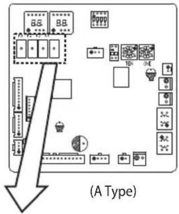


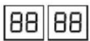
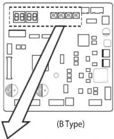


| K1 control KEY | operation Display on segment | |
| Press and hold 1 time | Auto trial operation "K""K""BLANK""BLANK" |
| K1 (Number of press) | KEY operation Display on segment | |
| 1 time Refrigerant charging in Heating mode "K""1""BLANK""BLANK" | ||
| 2 times Trial operation in Heating mode "K""2""BLANK""BLANK" | ||
| 3 times Pump out in Heating mode (Outdoor unit address 1) "K""3""BLANK""1" | ||
| 4 times Pump out in Heating mode (Outdoor unit address 2) "K""3""BLANK""2" | ||
| 5 times Pump out in Heating mode (Outdoor unit address 3) "K""3""BLANK""3" | ||
| 6 times Pump out in Heating mode (Outdoor unit address 4) "K""3""BLANK""4" | ||
| 7 times Vacuumig (Outdoor unit address 1) "K""4""BLANK""1" | ||
| 8 times Vacuumig (Outdoor unit address 2) "K""4""BLANK""2" | ||
| 9 times Vacuumig (Outdoor unit address 3) | "K""4""BLANK""3" | |
| 10 times | Vacuumig (Outdoor unit address 4) "K""4""BLANK""4" | |
| 11 times | Vacuuming (All outdoor units) | "K""4""BLANK""A" |
| 12 times | End Key operation | - |
| K2 (Number of press) | KEY operation Display on segment | |
| 1 time Refrigerant charging in Cooling mode “K”“5”“BLANK”“BLANK” | ||
| 2 times Trial operation in Cooling mode “K”“6”“BLANK”“BLANK” | ||
| 3 times Pump down all units in Cooling mode “K”“7”“BLANK”“BLANK” | ||
| 4 times Automatic setting of operation mode (Cooling/ Heating) for trail operation | “K”“8”“BLANK”“BLANK” | |
| 5 times Checking the amount of refrigerant | “K”“9”XX (Display of last two digits may differ depending on the progress) | |
| 6 times Discharge mode of DC link voltage “K”“A”“BLANK”“BLANK” | ||
| 7 times Forced defrost operation “K”“B”“BLANK”“BLANK” | ||
| 8 times Forced oil collection “K”“C”“BLANK”“BLANK” | ||
| 9 times Inverter compressor 1 check | “K”“D”“BLANK”“BLANK” | |
| 10 times Inverter compressor 2 check | “K”“E”“BLANK”“BLANK” | |
| 11 times Fan 1 check | “K”“F”“BLANK”“BLANK” | |
| 12 times Fan 2 check | “K”“G”“BLANK”“BLANK” | |
| 13 times End Key operation | - | |
* During "Discharge mode of DC link voltage", voltage of INV1 and INV2 will be displayed alternately.
* Even when the outdoor unit power is off, it is dangerous when you come in contact with inverter PCB and fan PCB since they are charged with high DC voltage.
* When replacing/repairing the PCB, cut-off the power and wait until the DC voltage is discharged before replacing/repairing them. (Wait for more than 15 minutes to allow it to discharge naturally.)
* When there were error, 'Dicharge mode of DC link voltage' may not have been effective. Especially if error E464 and E364 have been occurred, power element might be damaged by fire and therefore, do not use the 'Discharge mode of DC link voltage'.
| K3 (Number of press) | KEY operation Display on segment | |
| 1 time | Initialize (Reset) setting | Same as initial state |
Setting outdoor unit option switch and key function
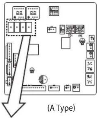
flowchart
graph TD
    A["Device Layout"] --> B["Display Icon"]
    A --> C["Control Icon"]
    A --> D["Data Storage Icon"]
    A --> E["Data Control Icon"]
    A --> F["Data Storage & Control Icon"]
    A --> G["Data Control & Data Storage Icon"]
    H["Arrow to (A Type)"] --> I["Arrow to (A Type)"]
    style A fill:#f9f,stroke:#333
    style I fill:#ccf,stroke:#333


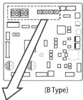


| K4 (Number of press) | KEY operation | Display on segment | |
| SEG 1 SEG2, 3, 4 | |||
| 1 time Outdoor unit model 1 AM160FXV | Off, 1, 6 | ||
| 2 times Order frequency (Compressor 1) 2 120 Hz | 1, 2, 0 | ||
| 3 times Order frequency (Compressor 2) 3 120 Hz | 1, 2, 0 | ||
| 4 times High pressure (MPa) 4 1.52 MPa | 1, 5, 2 | ||
| 5 times Low pressure (MPa) 5 0.43 MPa | 0, 4, 3 | ||
| 6 times | Discharge temperature (Compressor 1) | 6 | 87°C 0, 8, 7 |
| 7 times | Discharge temperature (Compressor 2) | 7 | 87°C 0, 8, 7 |
| 8 times | IPM temperature (Compressor 1) | 8 | 87°C 0, 8, 7 |
| 9 times | IPM temperature (Compressor 2) | 9 | 87°C 0, 8, 7 |
| 10 times | CT sensor value (Compressor 1) | A | 2 A 0, 2, 0 |
| 11 times | CT sensor value (Compressor 2) | B | 2 A 0, 2, 0 |
| 12 times | Suction temperature | C -42°C | -, 4, 2 |
| 13 times COND OUT temperautre D -42 °C | -, 4, 2 | ||
| 14 times | Temperature of liquid pipe | E | -42°C -, 4, 2 |
| 15 times | TOP temperature (Compressor 1) | F | -42°C -, 4, 2 |
| 16 times | TOP temperature (Compressor 2) G -42 °C | -, 4, 2 | |
| 17 times | Outdoor temperature | H -42°C | -, 4, 2 |
| 18 times EVI inlet temperature I | -42°C | -, 4, 2 | |
| 19 times | EVI outlet temperature | J | -42°C -, 4, 2 |
| 20 times | Main EEV1 step | K | 2000 steps 2, 0, 0 |
| 21 times | Main EEV2 step | L | 2000 steps 2, 0, 0 |
| 22 times | EVI EEV step | M | 300 steps 3, 0, 0 |
| 23 times | HR EEV step | N | 300 steps 3, 0, 0 |
| 24 times | Fan step (SSR or BLDC) | O | 13 steps 0, 1, 3 |
| 25 times | Current frequency (Compressor 1) | P | 120 Hz 1, 2, 0 |
| 26 times | Current frequency (Compressor 2) | Q | 120 Hz 1, 2, 0 |
| 27 times | Suction 2 temperature (H/R) | R | -42°C -, 4, 2 |
| 28 times | Master indoor unit address | S | Master indoor unit not selected BLANK, N, DIf indoor unit No.1 is selected as the master unit 0, 0, 1 |
| K4 (Number of press)Press and hold the K4 to enter the setting | Displayed content | Display on segment | |||
| page1 page2 | |||||
| 1 time Main version MAIN Version (ex. 1412) | |||||
| 2 times Hub version HUB Version (ex. 1412) | |||||
| 3 times Inverter 1 version INV1 Version (ex. 1412) | |||||
| 4 times Inverter 2 version INV2 Version (ex. 1412) | |||||
| 5 times Fan 1 version FAN1 Version (ex. 1412) | |||||
| 6 times Fan 2 version FAN2 Version (ex. 1412) | |||||
| 7 times EEP version EEP Version (ex. 1412) | |||||
| 8 times | Automatically assigned address of the units | AUTO | SEG1 SEG2 | SEG3, 4 | |
| Indoor unit: “A”MCU: “C” | Indoor unit: “0”MCU: “1” | Address(ex: 07) | |||
| 9 times Manually assigned address of the units MANU | SEG1 SEG2 | SEG3, 4 | |||
| Indoor unit: “A” | Indoor unit: “0” | Address(ex: 15) | |||
Things to check after completing the installation
- Before supplying the power, use DC 500 V insulation resistance tester to measure the power (3 phase: R, S, T / 1 phase: L, N) terminal and the outdoor unit grounding.
- Measurement should be over 30 MΩ.
- Before supplying the power, use a voltmeter and phase tester to check the voltage and the phase.
- R, S, T, N terminal: check if the voltage is 380 V between wires (R-S, S-T, T-R) and 220 V between phases (R-N, S-N, T-N) before turning on the switch.
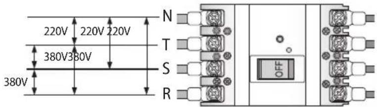
CAUTION
- Never measure the communication terminal since communication circuit may get damaged.
- Check for short-circuit of the communication terminal with a general circuit tester.
3. Check if the R-410A indoor units are connected.
4. When N phase is not correctly connected to R, S and T phase, over-voltage protection control will be in effect and it will cut-off the power of the PCB. Check the power cable connection of the N phase if the PCB is not turned on.
5. Check the following after the installation is completed.
| Installation work | Outdoor unit | Have you checked the external surface and the inside of the outdoor unit?Is there any possibility of short-circuit caused by the heat of an outdoor unit?Is the place well-ventilated and ensures space for service?Is the outdoor unit fixed securely to withstand any external force? |
| Indoor unit | Have you checked the external surface and the inside of the indoor unit?Is there enough space for service?Have you checked if the center of the indoor unit is ensured and it is installed horizontally? | |
| Refrigerant pipe work | Have you selected correct pipes?Are the liquid and gas valve open?Is the total number of connected indoor units within the allowable range?Are the length and the height difference between the refrigerant pipes within the allowable range?Are the branch joints properly installed?Did you check the connection of liquid and gas pipes?Have you selected correct insulator for pipes and insulated them correctly?Did you insulate the pipes and connection part correctly?Is the quantity of the additional refrigerant correctly weighed in? (You must record the amount of additional refrigerant on the service record paper placed inside of the outdoor unit.) | |
| Drain pipe work | Have you checked if the drain pipes of the indoor and outdoor unit are connected together?Have you completed the drain test?Is the drain pipe properly insulated? | |
| Electrical wiring work | Are the power cable and communication cable tightened firmly on the terminal board within the range of rated tightening torque?Have you checked for cross-connection of the power and communication cables?Have you performed the earthing work 3 to the outdoor unit?Did you make sure to use 2-core cable (not multi-core cable) for the communication cable?Is the length of the wire within allowed range?Is the wiring route correct? | |
| Setting address | Did you set the address of the indoor and outdoor units properly?Did you set the address of the indoor and outdoor units properly? (When using multiple remote controllers) | |
| Option | If there is a possibility of the outdoor unit from vibrating, check whether the anti-vibration frame is correctly installed. | |
Inspection and test operation

CAUTION
Precautions before test operation
- When the outdoor temperature is low, turn on the main power 6 hours before beginning the operation.
- If you start the operation immediately after turning on the main power, it may cause serious damage to the part within the product.
- Do not touch the refrigerant pipe during or right after the operation.
- Refrigerant pipe may be hot or cold during or right after the operation depending on the status of the refrigerant which flows through the refrigerant pipe, compressor and other parts of the refrigerant cycle.
- Do not operate the product with its panel or protection nets off.
- There is risk of personal injury from the parts that rotates, heated or with the high voltage.
- Do not turn off the main power immediately after stopping the operation.
- Wait for at least 5 minutes before turning off the main power. If not, water leakage or other problems may occur.
- Connect all the indoor units and the power supply for the outdoor unit and run auto address setting. Run auto address setting even after changing the indoor unit PCB.
Checklist before auto trial operation
- Check the power cable and communication cable of the indoor and outdoor unit.
- Supply power to the outdoor unit 6 hours before trial operation to pre-heat the crank case heater.
- Before supplying the power, use a voltmeter and phase tester to check the voltage and the phase.
- R, S, T, N terminal: check if the voltage is 380 V between wires (R-S, S-T, T-R) and 220 V between phases (R-N, S-N, T-N).
- When the power is supplied, outdoor unit will execute tracking to check the indoor unit connection and other optional functions.
- Write down the installation report on the service history report paper attached on the front part of the control box.

CAUTION
• Supply power to the outdoor unit 6 hours before auto trial operation to pre-heat the crank case heater.
6. Guaranteed range of auto trial operation
For precise judgment, you must perform auto trial operation in below indoor/outdoor temperature condition.
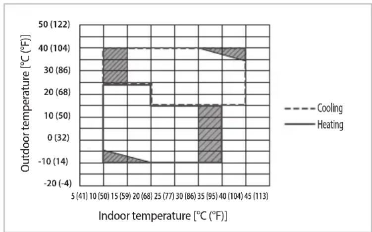
bar_line
| Indoor temperature [°C (°F)] | Outdoor temperature [°C (°F)] | Category | |---|---|---| | 5 (41) | 50 (122) | Heating | | 10 (50) | 40 (104) | Heating | | 15 (59) | 30 (86) | Heating | | 20 (68) | 20 (68) | Heating | | 25 (77) | 10 (50) | Heating | | 30 (86) | 10 (50) | Heating | | 35 (95) | 10 (50) | Heating | | 40 (104) | 40 (104) | Heating | | 45 (113) | 40 (104) | Heating | | 5 (41) | -10 (-14) | Heating | | 10 (50) | -10 (-14) | Heating | | 15 (59) | -10 (-14) | Heating | | 20 (68) | -10 (-14) | Heating | | 25 (77) | -10 (-14) | Heating | | 30 (86) | -10 (-14) | Heating | | 35 (95) | -10 (-14) | Heating | | 40 (104) | -10 (-14) | Heating | | 45 (113) | -10 (-14) | Heating |- In Auto trial operation, product will automatically select either cooling or heating mode and operate in selected mode.
- In the temperature range marked with slashed pattern, system protection control may trigger during operation. (If the system protection control is enabled, it can be hard to get the precise judgment after the auto trial operation.)
- When the temperature is outside of guaranteed range, accuracy of judgment on auto trial operation may decrease near boarder line area.
Auto trial operation
-
If the Auto Trial Operation is not completed, normal operation will be prohibited.
-
When the auto trial operation is not completed, UP (UnPrepared) will appear on the segment after the communication check and restrict compressor from operating. (UP Mode will be cleared automatically when auto trial mode is completed.)
- Auto trial operation may take 20 minutes to maximum 2 hours depending on the operation status.
-
During auto trial operation, noise can be generated due to vavle inspection. (Check the product if abnormal noise occurs continuously)
-
When error occurs during auto trial operation, check the error code and take appropriate measures.
-
Refer to next couple of pages when E503, E505 or E506 error occurs.
-
Refer to service manual if you need inspection or when other errors occur.
-
When auto trial operation ends, use S-NET pro or S-CHECKER to issue a result report.
-
Refer to service manual for further actions if you have any items with "inspection required" sign on the result report.
-
After taking appropriate measure for the items with "inpection required" sign, run the auto trial operation again.
-
Check the following items by running trial operation (cooling/heating).
-
Check if cooling/heating operation performs normally.
- Individual indoor unit control: Check for air flow direction and fan speed.
- Check for abnormal operation noise from the indoor and outdoor unit.
- Check for proper draining from the indoor unit during cooling operation.
-
Use S-NET pro to check the detail operation status.
-
Explain to the user how to use the air conditioner according to the user's manual.
-
Hand over the installation manual to the customer so they can keep it with them.
-
Explain to the user how to use the air conditioner according to the user's manual.
- Hand over the installation manual to the customer so they can keep it with them.

- Make sure to close the top and bottom part of the outdoor unit cabinet during operation. If you operate the unit with the front cabinet open, it may cause damage to the product and you may not get the precise data from S-NET pro.
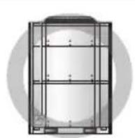
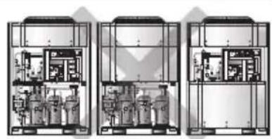
natural_image
Three-panel technical diagram showing internal components of an industrial or laboratory facility, with no visible text or symbols.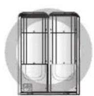
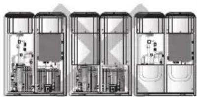
natural_image
Three-panel diagram showing internal layout of electronic devices or modules (no text or symbols visible)Inspection and trial operation
Measure to take when E503 error occurs (When "inspection required" sign is appeared on result report of S-NET pro)
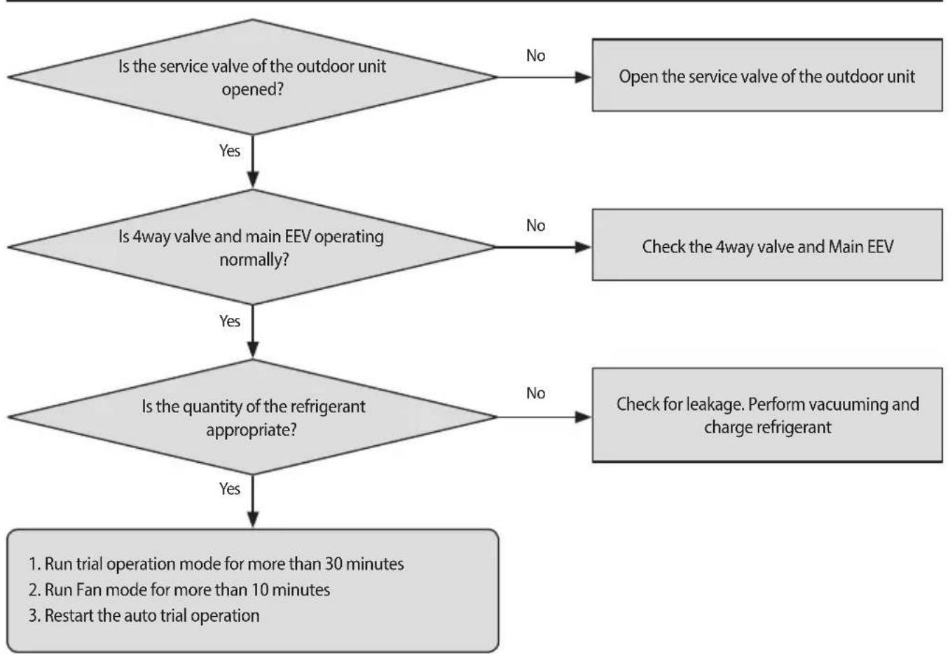
flowchart
graph TD
    A{Is the service valve of the outdoor unit opened?}
    B["Open the service valve of the outdoor unit"] -->|No| A
    A -->|Yes| C{Is 4way valve and main EEV operating normally?}
    C -->|No| D["Check the 4way valve and Main EEV"]
    C -->|Yes| E{Is the quantity of the refrigerant appropriate?}
    D --> E
    E -->|No| F["Check for leakage. Perform vacuuming and charge refrigerant"]
    E -->|Yes| G["1. Run trial operation mode for more than 30 minutes\n2. Run Fan mode for more than 10 minutes\n3. Restart the auto trial operation"]
* Symptoms for abnormal operation of the 4way valve
- Refrigerant noise is increased while compressor operates and temperature of the pipe inlet (H/P: Suction, H/R: Suction 2) remains over 10^ (50^) compared to low pressure's saturation temperature.
- Temperature of Eva. in/out remains below 0 °C (32 °F) during heating operation.
* Symptoms for abnormal operation of the Main EEV
- Error on controlling degree of superheat of compressor inlet during heating operation.
: If there's operation error while the EEV is fully opened, targeted degree of superheat [1 °C (33.8 °F)] cannot be secured [below 0 °C (32 °F)] and discharge temperature of the compressor will be low.
: If there's operation error while the EEV is fully closed, low pressure will decrease and the degree of superheat on the compressor inlet will increase excessively.

- If the service valve need to be detected, corresponding outdoor unit will display the error.
- If the service valve need to be detected, auto detection mode will end. Check both gas pipe and liquid pipe service valves when detecting service valve.
- When 4way valve, Main EEV detection is needed, run heating trial operation for more than 1 hour and analyze the data to check for a problem.
- If there's frost formed in outdoor unit or the outdoor unit is operating in deforst operation, it may be hard to detect problem normally. In this case, run heating trial operation for more than 1 hour.
- If the operation range is not within guaranteed range, error may occur even though the product is normal.
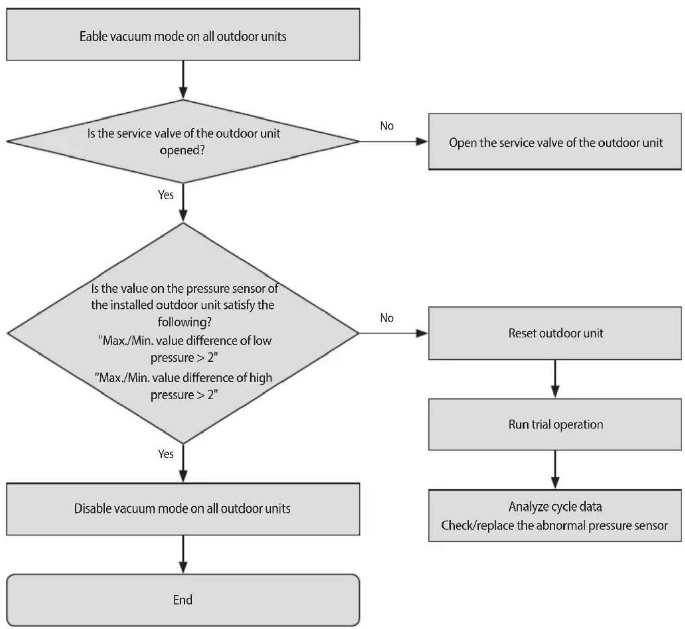
flowchart
graph TD
    A["Eable vacuum mode on all outdoor units"] --> B{Is the service valve of the outdoor unit opened?}
    B -->|No| C["Open the service valve of the outdoor unit"]
    B -->|Yes| D{Is the value on the pressure sensor of the installed outdoor unit satisfy the following? "Max./Min. value difference of low pressure > 2" "Max./Min. value difference of high pressure > 2"}
    D -->|No| E["Reset outdoor unit"]
    E --> F["Run trial operation"]
    F --> G["Analyze cycle data\nCheck/replace the abnormal pressure sensor"]
    D -->|Yes| H["Disable vacuum mode on all outdoor units"]
    H --> I["End"]

- When the auto trial operation for pressure sensor was executed before the pressure of the outdoor unit is equilized (when there's close to no difference between high and low pressure), error may occur even though the product is normal.
• If the pressure sensor need to be detected, all outdoor units will display the error.
• If the pressure sensor need to be detected, auto trial operation mode will end. - To check for the pressure sensor with the problem, run trial operation for more than 1 hour and analyze the data to check for a problem.
Automatic refrigerant amount detection function
This function detects amount of refrigerant in the system through refrigerant amount detection operation
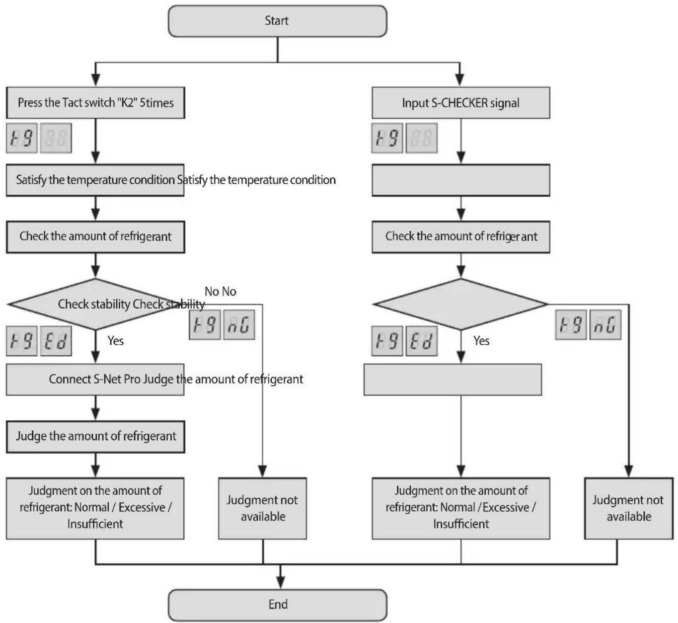
flowchart
graph TD
    A["Start"] --> B["Press the Tact switch "K2" 5 times"]
    A --> C["Input S-CHECKER signal"]
    B --> D["Satisfy the temperature condition Satisfy the temperature condition"]
    D --> E["Check the amount of refrigerant"]
    E --> F{Check stability Check stability}
    F -->|Yes| G["Connect S-Net Pro Judge the amount of refrigerant"]
    F -->|No| H["Judgment not available"]
    G --> I["Judge on the amount of refrigerant: Normal / Excessive / Insufficient"]
    I --> J["End"]
    C --> K["Check the amount of refrigerator"]
    K --> L["Judgment on the amount of refrigerant: Normal / Excessive / Insufficient"]
    L --> M["End"]
    C --> N["End"]
    style A fill:#ccc,stroke:#333
    style B fill:#ccc,stroke:#333
    style C fill:#ccc,stroke:#333
    style D fill:#ccc,stroke:#333
    style E fill:#ccc,stroke:#333
    style F fill:#ccc,stroke:#333
    style G fill:#ccc,stroke:#333
    style H fill:#ccc,stroke:#333
    style I fill:#ccc,stroke:#333
    style J fill:#ccc,stroke:#333
    style K fill:#ccc,stroke:#333
    style L fill:#ccc,stroke:#333
    style M fill:#ccc,stroke:#333
    style N fill:#ccc,stroke:#333
* After refrigerant amount detection is finished if you see "K9 Ed" on the display and cannot check the refrigerant amount from the S-net pro and S-checker, it means insufficient degree of supercooling.

- If the temperature is out of the guaranteed range below, exact result will not be obtained.
- Indoor: 20\~32 °C
- Outdoor: 5\~43 °C
- If the operation cycle is not stable, the operation of refrigerant amount check may be forcibly finished.
- Accuracy of the result may decrease if the product has not been operated for a long period of time or heat mode has been operated before running the function of refrigerant amount check. Therefore, use the function of refrigerant amount check after operating the product in cool mode for at least 30 minutes.
- Product may trigger system protection operation depending on the installation environment. In this case, the result of refrigerant amount check may not be accurate.
Actions to take for the check result
• Excessive amount of refrigerant
- Discharge 5% of total amount of refrigerant and restart the refrigerant amount check.
• Insufficient amount of refrigerant
- Add 5% of the total amount of refrigerant and restart the refrigerant amount check.
• Insufficient degree of supercooling
- Add 10% of the total amount of refrigerant and restart the refrigerant amount check.
• Judgment not available
- Check if the function of refrigerant amount check is executed within the guaranteed temperature range. Run trial operation to check if there are other problems on the system.