
AM180CXVAFH - Séparateur SAMSUNG - Free user manual and instructions
Find the device manual for free AM180CXVAFH SAMSUNG in PDF.

| Product Type | Split Air Conditioner |
| Model | AM180CXVAFH |
| Brand | Samsung |
| Cooling Capacity | 18,000 BTU/h |
| Heating Capacity | 20,000 BTU/h |
| Power Supply | 208-230V / 60Hz |
| Indoor Unit Dimensions (WxHxD) | 39.0 x 12.5 x 9.8 inches |
| Outdoor Unit Dimensions (WxHxD) | 34.0 x 24.5 x 14.0 inches |
| Indoor Unit Weight | 28 lbs |
| Outdoor Unit Weight | 88 lbs |
| Refrigerant Type | R-410A |
| Seasonal Energy Efficiency Ratio (SEER) | 16 SEER |
| Main Functions | Cooling, Heating, Dehumidification, Fan |
| Controls | Remote Control with LCD Display |
| Air Filter | Washable, Anti-bacterial |
| Maintenance & Cleaning | Clean filter every 2 weeks; annual professional service |
| Safety Features | Overload protection, auto restart, child lock |
| Spare Parts & Repairability | Replacement filters, remote, and main PCB available |
| Warranty | 1 year parts and labor; 5 years compressor |
| General Information | Designed for residential use; suitable for rooms up to 1000 sq ft |
Frequently Asked Questions - AM180CXVAFH SAMSUNG
User questions about AM180CXVAFH SAMSUNG
0 question about this device. Answer the ones you know or ask your own.
Ask a new question about this device
Download the instructions for your Séparateur in PDF format for free! Find your manual AM180CXVAFH - SAMSUNG and take your electronic device back in hand. On this page are published all the documents necessary for the use of your device. AM180CXVAFH by SAMSUNG.
USER MANUAL AM180CXVAFH SAMSUNG
- Thank you for purchasing this Samsung air conditioner.
- Before operating this unit, please read this installation manual carefully and retain it for future reference.

SAMSUNG
Contents
Safety Information 3
Safety Information 3
Installation Procedure 5
Preparations for Outdoor Unit 5
Choosing the installation location 10
Preparing materials and tools 12
Outdoor unit installation 12
Refrigerant pipe installation 17
Electrical wiring work 32
Air tightness test and vacuum drying 39
Pipe insulation 41
Basic segment display 44
Setting outdoor unit option switch and key function 45
Performing final checks and trial operation 53
Appendix 55
Inspection and trial operation 55
Automatic refrigerant amount detection function 57
2 English
Safety Information
Please follow the following safety information for safety of the installer and the user.
• DVM S2 air conditioner uses R-410A refrigerant.
- When using R-410A, moisture or foreign substances may affect the performance and reliability of the product. Safety precautions must be obeyed when installing the refrigerant pipe.
- The designed maximum pressure of the system is 4.1MPa and therefore select appropriate material and thickness according to the regulations.
-
R-410A is a quasi-azetrope of two refrigerants and it has to be charged in liquid phase when filling the refrigerant. (If you charge vapor refrigerant, it may change the blend of the refrigerant and cause product malfunction.)
-
You must connect the indoor units for R-410A refrigerant. Refer to product catalog to find out the models names for connectable indoor units. (If you connect the indoor units that are not designed for R-410A, it cannot operate normally.)
- After completing the installation and trial operation, explain to the user how to use and maintain the product. Also, hand over this installation manual so that it can be stored by the user.
- Manufacturer is not responsible for the incidents occurred by improper installation. Installer is responsible for any installation related claims from the user occurred by neglecting warnings and cautions stated in this manual. (Installer will be responsible for any service charges that may occur)
- Generally, system air conditioners should not be relocated after installation. But when it has to be relocated for inevitable reasons, please contact Samsung's qualified dealers for system air conditioners.

WARNING
- Hazards or unsafe practices that may result in severe personal injury or death.

CAUTION
- Hazards or unsafe practices that may result in minor personal injury (to installer/user) or property damage.
General information

WARNING
- Consult qualified installer or dealer for installation.
- When installation is done by unqualified person, problems such as water leakage, electric shock or fire may occur.
• Installation work must be done properly according to this installation manual.
- When installation is not done properly, it may cause water leakage, electric shock or fire.
- When installing the unit in a small room, take measure to keep the refrigerant concentration from exceeding allowable safety limits in case of refrigerant leakage. Consult the dealer for precautionary measure before the installation.
When refrigerant leaks and exceed dangerous concentration level, it may cause suffocation accidents.
- If any gas or impurities, except R-410A refrigerant, come into the refrigerant pipe, serious problem may occur and it may cause injury.
- Use the supplied accessories, specified components and tools for the installation.
- Do not use the pipe and the installation product used for refrigerants except R-410A.
- Failure to use the specified components can cause product fall down, water leakage, electrical shock, and fire. (The pipe and flare components used for refrigerants except R-410A must not be used)
• Install the outdoor unit on a hard and even place that can support its weight.
- If the place cannot support its weight, the outdoor unit may fall down and it may cause injury.
- Check the following before installation and service work.
- Before welding, remove dangerous and inflammable things that may cause an explosion and fire around the work.
- Before welding, remove the refrigerant from inside the pipe or the product.
- If you perform welding while refrigerant is in the pipe, it may increase the pressure of the refrigerant and cause the pipe to burst. If the pipe bursts or explodes, it may cause severe injury to the installer.
- When welding, use the nitrogen gas to eliminate oxidation inside the pipe.
- Do not modify the product on your own.
- Potential risk of electric shock, fire, product failure or injury.
- Fix the outdoor unit securely on foundation to resist strong wind or earthquake.
If the outdoor unit is not properly fixed, it turns over and accidents may occur.
- Electric work must be done by qualified persons, complying the national wiring regulations and installed according to the instruction stated in the installation manual with leased circuit.
- Capacity shortage on the leased circuit and improper installation may cause electric shock or fire.
• Make sure to perform grounding work.
- Do not connect the ground wire to a gas pipe, water pipe, lightning rod or telephone grounding. Improper grounding could cause electric shock.
- Wiring must be connected with the designated wires and it must be fixed securely so that it does not apply any external force to the connection part of the terminals.
- If connection for fixation is not properly done, it may cause heat generation or fire.
- Neatly arrange the wires in the electrical parts to make sure that electrical cover is closed securely without any gaps.
- If the cover is not properly closed, heat may generate on the electrical terminal and cause electric shock or fire.
- Exclusive circuit breaker (MCCB, ELB) must be installed to the power supply.
- When overcurrent or current leakage occurs with no circuit breaker installed, power will not be cut-off and it may cause electric shock or fire.
- Do not use damaged parts. It may cause fire or electric shock.
- You must cut-off the power before you work on, or adjust any power supply part for product installation, maintenance, repair or any other services.
- There is risk of electric shock.
- Even when the power is off, it is dangerous when you come in contact with inverter PCB, fan PCB since high pressure DC voltage is charged to those parts.
Safety Information
- When replacing/repairing the PCB, cut-off the power and wait until the DC voltage is discharged before replacing/repairing them. (Wait for more than 15 minutes to allow it to discharge naturally.)
- If the refrigerant gas leaks during the installation, you should ventilate the room.
- When the refrigerant gas gets in contact with flammable substance, it may generate toxic gas.
• Gas leakage must be checked after installation is completed.
- When the refrigerant gas gets in contact with flammable substance, it may generate toxic gas.
- You can get a frostbite if you get in contact with the leaked refrigerant gas.
- Supply power to the product during winter time since the product will operate in protection mode itself when the temperature decrease below 0°C (32°F).
- If you cut-off the power, compressor protection mode cannot be operated and may cause damage to the product.
- Wear protective equipment (such as safety gloves, goggles, and headgear) during installation and maintenance works. Installation/repair technicians may be injured if protective equipment is not properly equipped.
- This appliance is not intended for use by persons (including children) with reduced physical, sensory or mental capabilities, or lack of experience and knowledge, unless they have been given supervision or instruction concerning use of the appliance by a person responsible for their safety. Children should be supervised to ensure that they do not play with the appliance.
For use in Europe: This appliance can be used by children aged from 8 years and above and persons with reduced physical, sensory or mental capabilities or lack of experience and knowledge if they have been given supervision or instruction concerning use of the appliance in a safe way and understand the hazards involved. Children shall not play with the appliance. Cleaning and user maintenance shall not be made by children without supervision.
CAUTION
- Do not install the drain pipe directly to the bottom part of the outdoor unit and built a proper drainage so that water drains out smoothly. If not, pipe may freeze or bursts during winter time and cause damage to the product or water leakage.
- When the draining work is not done properly, water leak may occur and cause property damage.
- Install the power cable and communication cable of the indoor and outdoor unit at least 1.5m (4.92ft) away from the electric appliances and install it at least 2m (6.56ft) away from the lightning conductor.
– Noise may be generated from the electronic devices, depending on the status of the electric wave.
• Install the outdoor unit within the angle stated in the table, according to the height of the building.
- Do not leave the refrigerant container under the hot sunlight. (There is risk of explosion.)
- You must use the appropriate pipes according to the standard since the pressure of the refrigerant is high.
- Make sure that the pipes does not get any weaker by welding it too much.
- Make sure to install the product away from children's reach. (Sharp parts of the heat exchanger may cause personal injury and when parts of the product gets damage, it may decrease product's performance.)
Lightning rod
Protection angle: 25°\~55°
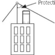
| Height of the building Protection angle | |
| 20m(65.6 ft) or less 55" | |
| 40m(131.2 ft) or less 35" | |
| 60m(196.9 ft) or less 25" | |
• Install the indoor unit away from lighting apparatus that uses ballast stabilizer.
- If you use the wireless remote control, it may not operate normally due to ballast stabilizer.
- Do not install the product in following places.
- Place where outdoor unit's noise and warm air may disturb neighbors. (It may cause property loss.)
- Do not leave any obstacles around the inlet and outlet of the product. (It may cause damage or accidents.)
– The place where there is mineral oil or arsenic acid.
– Those parts may get damaged due to burned resin and cause water leakage or product may fall.
- The efficiency of the heat exchanger may reduce or product may break.
- The place where corrosive gas such as sulfurous acid gas generates from the vent pipe or air outlet.
- The copper pipe or connection pipe may corrode and refrigerant may leak.
- The place where there is a machine that generates electromagnetic waves.
- The air conditioner may not operate normally due to problems in control system.
- The place where there is a danger of combustible gas leakage or place where thinner or gasoline is handled.
- (There is risk of fire or explosion.)
– The place with carbon fiber or flammable dust. - The place near seashore or hot spring where there is risk of outdoor unit corrosion.
- Changes in DVM S2 (inverter) compare to conventional models that has to noted when installing
- For optimal distribution of the refrigerant, you must use Y-joint as branch joint for connecting outdoor units. (Do not use T-joint)
- You cannot operate normally if you do not complete the trial operation through outdoor unit key mode. You must use KEY MODE to run trial operation.
- Check the compatibility of other products such as indoor unit, EEV kits etc. which will be connected to DVM S2.
- Make sure to note that outdoor unit combination is different from DVM PLUS III, IV and DVM S.
- The length of maximum piping, level difference, the quantity of connectable indoor units, the installation at the outdoor joints and the outdoor unit combinations are different from the conventional models.
- If the pipe length is over 2m (6.56ft) between outdoor units, make traps to prevent oil stagnation. Oil stagnation may occur when outdoor unit at the end of module stops while other outdoor units are still in operation.
4 English
Preparations for Outdoor Unit
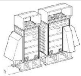
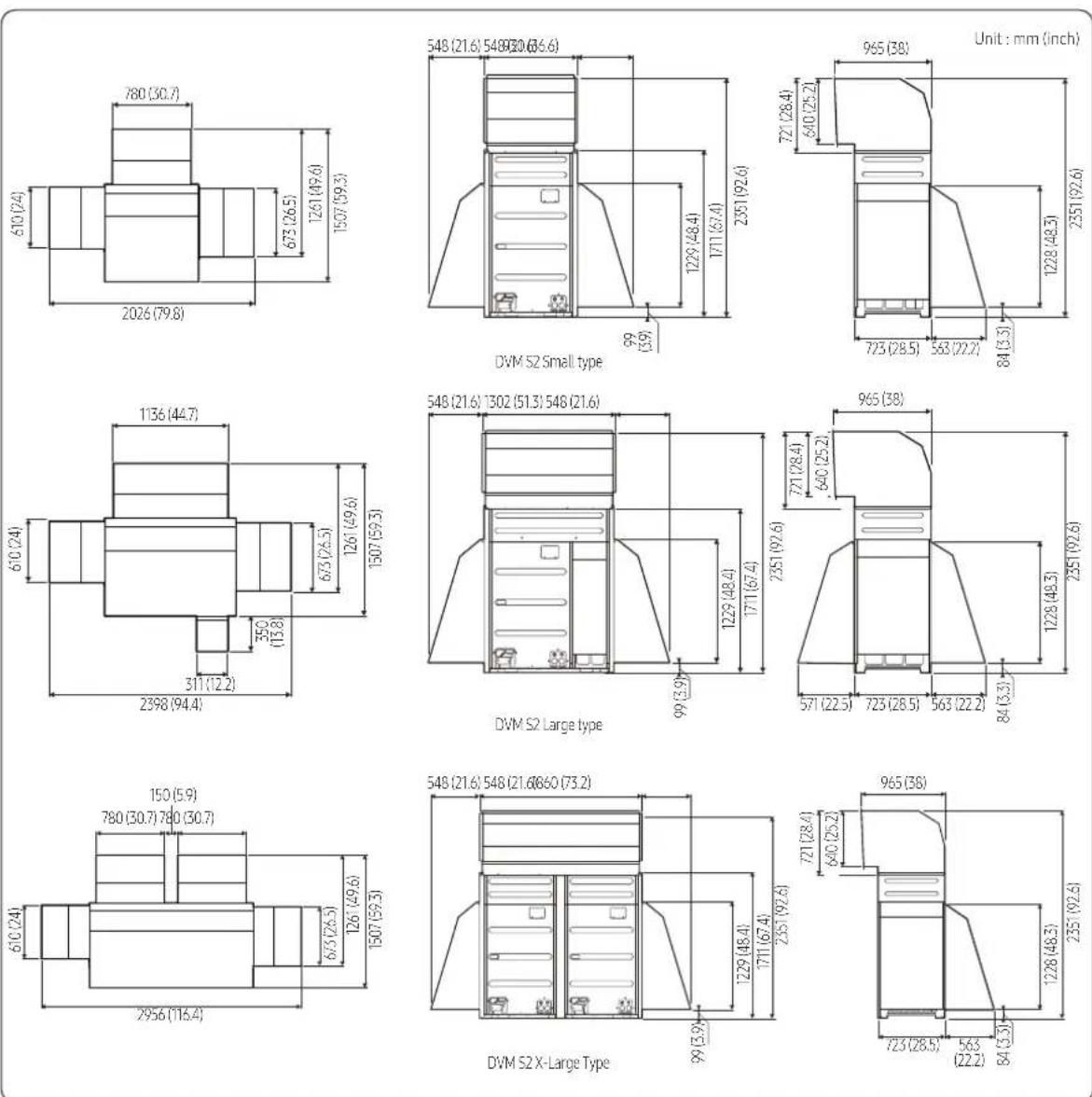
Outdoor unit classification
| Classification | DVM S2 Small type | DVM S2 Large type | DVM S2 X-Large type |
| Appearance | 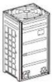 | 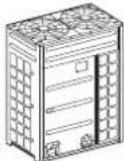 | 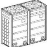 |

CAUTION
Packaging material disposition
- Safely store or dispose the packaging materials.
- Sharp metals such as nails or wooden material packaging that may break into pieces become a cause for personal injury.
- Make sure to store or dispose the vinyl type packaging material to keep it out of reach of children. Children may put them over their face, which is very dangerous since it may lead them to suffocation.
Moving the outdoor unit
- Select the moving path in advance.
- Be sure that moving path can support weight of the outdoor unit.
- Do not slant the product more than 30^ when carrying it. (Do not lay the product down in sideways.)
- Surface of the heat exchanger is sharp. Be careful not to get injured while moving the product.
- When transporting DVM S2 outdoor, be aware of the center of gravity of the outdoor (Please refer to the center of gravity label attached on the front panel, and remove it after installation.)

CAUTION
- You must use certain part of the product when moving the product.
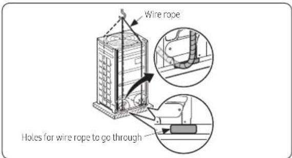
When moving with a crane
- Fasten the wire rope as shown in the figure.
- To protect damage or scratches, insert a piece of cloth between the outdoor unit and the wire rope.
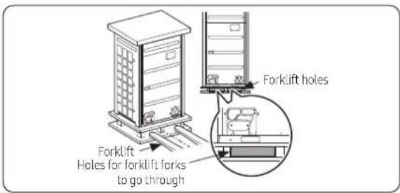
When moving with a forklift
- Carefully insert the forklift forks into the forklift holes at the bottom of the outdoor unit.
- Be careful with the forklift from damaging the product.
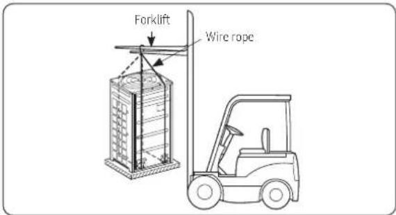
When moving the product without wooden pallet and the crane is not available for use
- Connect a wire rope to the outdoor unit as you would move it with a crane.
- Hang the wire rope to the forklift fork to move the outdoor unit.
Outdoor unit combination
- Make sure to use an indoor unit that is compatible with DVM S2.
- Indoor units can be connected within the range indicated in following table.
- If the total capacity of the connected indoor units exceeds the indicated maximum capacity, cooling and heating capacity of the indoor unit may decrease.
- Total capacity of the connected indoor units can be allowed from 50% to 130% of the total outdoor unit capacity. 0.5 × (Outdoor unit capacity) ≤ Total capacity of the connected indoor units ≤ 1.3 × (Outdoor unit capacity)
- Please contact your local Samsung representative or refer to the Technical Data Book for further details if the project requires you to design the project with a connection ratio greater than 130%.
- You can connect maximum 64 indoor units to the outdoor unit. Maximum quantity of connectable indoor unit is set to 64 since outdoor unit only support up to 64 communication address. Indoor unit address can be assigned from 0\~63. If the indoor unit address was assigned from 64\~79, E201 error will occur.
- Maximum 32 Wall-mount type indoor units with EEV (AM****NQD*, AM****NVD*) can be connected.
- Do not install 1st-generation MCU and 2nd-generation MCU together.
- 1st-generation MCU: MCU-S*NEE*N, MCU-S2NEK1N
- 2nd-generation MCU: MCU-S*NEK2N, MCU-S4NEK3N, MCU-S1NEK1N

CAUTION
- Use the following table to determine the size and number of outdoor units needed to achieve the capacity requirements.
English 5
Preparations for Outdoor Unit
Module combination for AM***CXVAFH series
| Model name for combination | Number of individual outdoor units | Rated Capacity | Total cooling capacity of the connected indoor units | Maximum number of connectable indoor units | Combined outdoor units | |||||||||||
| AM***CXVAFH | ||||||||||||||||
| Cooling (Btu/h) | Heating (Btu/h) | Minimum (Btu/h) | Maximum (Btu/h) | 080 | 100 | 120 | 140 | 160 | 180 | 200 | 220 | 240 | 260 | |||
| AM080CXVAFH | 1 | 76,400 | 86,000 | 38,200 | 99,300 | 14 | 1 | |||||||||
| AM100CXVAFH | 1 | 95,500 | 107,500 | 47,800 | 124,200 | 18 | 1 | |||||||||
| AM120CXVAFH | 1 | 114,600 | 129,000 | 57,300 | 149,100 | 21 | 1 | |||||||||
| AM140CXVAFH | 1 | 136,500 | 153,500 | 68,200 | 177,400 | 26 | 1 | |||||||||
| AM160CXVAFH | 1 | 153,500 | 172,000 | 76,800 | 199,600 | 29 | 1 | |||||||||
| AM180CXVAFH | 1 | 172,000 | 193,500 | 86,000 | 223,500 | 32 | 1 | |||||||||
| AM200CXVAFH | 1 | 191,100 | 215,000 | 95,500 | 248,400 | 36 | 1 | |||||||||
| AM220CXVAFH | 1 | 210,200 | 236,500 | 105,100 | 273,300 | 40 | 1 | |||||||||
| AM240CXVAFH | 1 | 229,300 | 258,000 | 114,700 | 298,200 | 43 | 1 | |||||||||
| AM260CXVAFH | 1 | 248,400 | 267,500 | 124,200 | 322,800 | 47 | 1 | |||||||||
| AM280CXVAFH | 2 | 268,200 | 301,000 | 134,100 | 348,700 | 51 | 1 | 1 | ||||||||
| AM300CXVAFH | 2 | 286,600 | 322,400 | 143,300 | 372,600 | 54 | 1 | 1 | ||||||||
| AM320CXVAFH | 2 | 305,700 | 343,900 | 152,900 | 397,500 | 58 | 1 | 1 | ||||||||
| AM340CXVAFH | 2 | 324,800 | 365,400 | 162,400 | 422,500 | 61 | 1 | 1 | ||||||||
| AM360CXVAFH | 2 | 343,900 | 386,900 | 172,000 | 447,000 | 64 | 1 | 1 | ||||||||
| AM380CXVAFH | 2 | 363,100 | 396,500 | 181,500 | 471,900 | 64 | 1 | 1 | ||||||||
| AM400CXVAFH | 2 | 382,200 | 429,900 | 191,100 | 496,800 | 64 | 2 | |||||||||
| AM420CXVAFH | 2 | 401,300 | 451,400 | 200,600 | 521,800 | 64 | 1 | 1 | ||||||||
| AM440CXVAFH | 2 | 420,400 | 472,900 | 210,200 | 546,700 | 64 | 2 | |||||||||
| AM460CXVAFH | 2 | 439,500 | 494,400 | 219,800 | 571,200 | 64 | 1 | 1 | ||||||||
| AM480CXVAFH | 2 | 458,600 | 515,900 | 229,300 | 596,100 | 64 | 2 | |||||||||
| AM500CXVAFH | 2 | 477,700 | 525,500 | 238,900 | 621,100 | 64 | 1 | 1 | ||||||||
| AM520CXVAFH | 2 | 496,800 | 535,000 | 248,400 | 646,000 | 64 | 2 | |||||||||
| AM540CXVAFH | 3 | 515,900 | 580,400 | 258,000 | 670,900 | 64 | 1 | 1 | 1 | |||||||
| AM560CXVAFH | 3 | 535,000 | 601,900 | 267,500 | 695,400 | 64 | 1 | 2 | ||||||||
| AM580CXVAFH | 3 | 554,100 | 623,400 | 277,100 | 720,400 | 64 | 1 | 1 | 1 | |||||||
| AM600CXVAFH | 3 | 573,200 | 644,900 | 286,600 | 745,300 | 64 | 1 | 2 | ||||||||
| AM620CXVAFH | 3 | 592,300 | 654,400 | 296,200 | 770,200 | 64 | 1 | 1 | 1 | |||||||
| AM640CXVAFH | 3 | 611,500 | 664,000 | 305,800 | 795,100 | 64 | 1 | 2 | ||||||||
| AM660CXVAFH | 3 | 630,600 | 709,400 | 315,300 | 819,700 | 64 | 3 | |||||||||
| AM680CXVAFH | 3 | 649,700 | 730,900 | 324,900 | 844,600 | 64 | 2 | 1 | ||||||||
| AM700CXVAFH | 3 | 668,800 | 740,400 | 334,400 | 869,500 | 64 | 2 | 1 | ||||||||
| AM720CXVAFH | 3 | 687,900 | 761,900 | 344,000 | 894,400 | 64 | 1 | 1 | 1 | |||||||
| AM740CXVAFH | 3 | 707,000 | 783,400 | 353,500 | 919,300 | 64 | 2 | 1 | ||||||||
| AM760CXVAFH | 3 | 726,100 | 793,000 | 363,100 | 943,900 | 64 | 1 | 2 | ||||||||
| AM780CXVAFH | 3 | 745,200 | 802,500 | 372,600 | 968,800 | 64 | 3 | |||||||||
| AM800CXVAFH | 4 | 764,300 | 859,900 | 382,200 | 993,700 | 64 | 1 | 2 | 1 | |||||||
| AM820CXVAFH | 4 | 783,400 | 881,400 | 391,700 | 1,018,600 | 64 | 1 | 1 | 2 | |||||||
| AM840CXVAFH | 4 | 802,500 | 902,900 | 401,300 | 1,043,500 | 64 | 1 | 3 | ||||||||
| AM860CXVAFH | 4 | 821,600 | 912,400 | 410,900 | 1,068,100 | 64 | 1 | 2 | 1 | |||||||
| AM880CXVAFH | 4 840 | 800 | 922,000 | 420,400 | 1,093,000 | 64 | 1 | 1 | 2 | |||||||
| AM900CXVAFH | 4 | 859,900 | 931,500 | 430,000 | 1,117,900 | 64 | 1 | 3 | ||||||||
| AM920CXVAFH | 4 | 879,600 | 965,000 | 439,900 | 1,143,500 | 64 | 1 | 1 | 2 | |||||||
| AM940CXVAFH | 4 | 898,800 | 974,500 | 449,400 | 1,168,400 | 64 | 1 | 3 | ||||||||
| AM960CXVAFH | 4 | 917,200 | 1,007,900 | 458,600 | 1,192,300 | 64 | 2 | 2 | ||||||||
| AM980CXVAFH | 4 | 936,300 | 1,029,400 | 468,200 | 1,217,200 | 64 | 1 | 1 | 2 | |||||||
English
Module combination for AM***CXVAFC series
| Model name for combination | Number of Individual outdoor units | Rated Capacity | Total cooling capacity of the connected indoor units | Maximum number of connectable indoor units | Combined outdoor units | |||||||||||
| AM***CXVAFC | ||||||||||||||||
| Cooling (Btu/h) | Heating (Btu/h) | Minimum (Btu/h) | Maximum (Btu/h) | 080 | 100 | 120 | 140 | 160 | 180 | 200 | 220 | 240 | 260 | |||
| AM080CXVAFC | 1 | 76,400 | - | 38,200 | 99,300 | 14 | 1 | |||||||||
| AM100CXVAFC | 1 | 95,500 | - | 47,800 | 124,200 | 18 | 1 | |||||||||
| AM120CXVAFC | 1 | 114,600 | - | 57,300 | 149,100 | 21 | 1 | |||||||||
| AM140CXVAFC | 1 | 136,500 | - | 68,200 | 177,400 | 26 | 1 | |||||||||
| AM160CXVAFC | 1 | 153,500 | - | 76,800 | 199,600 | 29 | 1 | |||||||||
| AM180CXVAFC | 1 | 172,000 | - | 86,000 | 223,500 | 32 | 1 | |||||||||
| AM200CXVAFC | 1 | 191,100 | - | 95,500 | 248,400 | 36 | 1 | |||||||||
| AM220CXVAFC | 1 | 210,200 | - | 105,100 | 273,300 | 40 | 1 | |||||||||
| AM240CXVAFC | 1 | 229,300 | - | 114,700 | 298,200 | 43 | 1 | |||||||||
| AM260CXVAFC | 1 | 248,400 | - | 124,200 | 322,800 | 47 | 1 | |||||||||
| AM280CXVAFC | 2 | 268,200 | - | 134,100 | 348,700 | 51 | 1 | 1 | ||||||||
| AM300CXVAFC | 2 | 286,600 | - | 143,300 | 372,600 | 54 | 1 | 1 | ||||||||
| AM320CXVAFC | 2 | 305,700 | - | 152,900 | 397,500 | 58 | 1 | 1 | ||||||||
| AM340CXVAFC | 2 | 324,800 | - | 162,400 | 422,500 | 61 | 1 | 1 | ||||||||
| AM360CXVAFC | 2 | 343,900 | - | 172,000 | 447,000 | 64 | 1 | 1 | ||||||||
| AM380CXVAFC | 2 | 363,100 | - | 181,500 | 471,900 | 64 | 1 | 1 | ||||||||
| AM400CXVAFC | 2 | 382,200 | - | 191,100 | 496,800 | 64 | 1 | 1 | ||||||||
| AM420CXVAFC | 2 | 401,300 | - | 200,600 | 521,800 | 64 | 1 | 1 | ||||||||
| AM440CXVAFC | 2 | 420,400 | - | 210,200 | 546,700 | 64 | 2 | |||||||||
| AM460CXVAFC | 2 | 439,500 | - | 219,800 | 571,200 | 64 | 1 | 1 | ||||||||
| AM480CXVAFC | 2 | 458,600 | - | 229,300 | 596,100 | 64 | 2 | |||||||||
| AM500CXVAFC | 2 | 477,700 | - | 238,900 | 621,100 | 64 | 1 | 1 | ||||||||
| AM520CXVAFC | 2 | 496,800 | - | 248,400 | 646,000 | 64 | 2 | |||||||||
| AM540CXVAFC | 3 | 515,900 | - | 258,000 | 670,900 | 64 | 1 | 1 | 1 | |||||||
| AM560CXVAFC | 3 | 535,000 | - | 267,500 | 695,400 | 64 | 1 | 2 | ||||||||
| AM580CXVAFC | 3 | 554,100 | - | 277,100 | 720,400 | 64 | 1 | 1 | 1 | |||||||
| AM600CXVAFC | 3 | 573,200 | - | 286,600 | 745,300 | 64 | 1 | 2 | ||||||||
| AM620CXVAFC | 3 | 592,300 | - | 296,200 | 770,200 | 64 | 1 | 1 | 1 | |||||||
| AM640CXVAFC | 3 | 611,500 | - | 305,800 | 795,100 | 64 | 1 | 2 | ||||||||
| AM660CXVAFC | 3 | 630,600 | - | 315,300 | 819,700 | 64 | 1 | 1 | 1 | |||||||
| AM680CXVAFC | 3 | 649,700 | - | 324,900 | 844,600 | 64 | 2 | 1 | ||||||||
| AM700CXVAFC | 3 | 668,800 | - | 334,400 | 869,500 | 64 | 2 | 1 | ||||||||
| AM720CXVAFC | 3 | 687,900 | - | 344,000 | 894,400 | 64 | 1 | 1 | 1 | |||||||
| AM740CXVAFC | 3 | 707,000 | - | 353,500 | 919,300 | 64 | 2 | 1 | ||||||||
| AM760CXVAFC | 3 | 726,100 | - | 363,100 | 943,900 | 64 | 1 | 2 | ||||||||
| AM780CXVAFC | 3 | 745,200 | - | 372,600 | 968,800 | 64 | 3 | |||||||||
| AM800CXVAFC | 4 | 764,300 | - | 382,200 | 993,700 | 64 | 1 | 2 | 1 | |||||||
| AM820CXVAFC | 4 | 783,400 | - | 391,700 | 1,018,600 | 64 | 1 | 1 | 2 | |||||||
| AM840CXVAFC | 4 | 802,500 | - | 401,300 | 1,043,500 | 64 | 1 | 3 | ||||||||
| AM860CXVAFC | 4 | 821,600 | - | 410,900 | 1,068,100 | 64 | 1 | 2 | 1 | |||||||
| AM880CXVAFC | 4 | 840,800 | - | 420,400 | 1,093,000 | 64 | 1 | 1 | 2 | |||||||
| AM900CXVAFC | 4 | 859,900 | - | 430,000 | 1,117,900 | 64 | 1 | 3 | ||||||||
| AM920CXVAFC | 4 | 879,600 | - | 439,900 | 1,143,500 | 64 | 1 | 1 | 2 | |||||||
| AM940CXVAFC | 4 | 898,800 | - | 449,400 | 1,168,400 | 64 | 1 | 3 | ||||||||
| AM960CXVAFC | 4 | 917,200 | - | 458,600 | 1,192,300 | 64 | 2 | 2 | ||||||||
| AM980CXVAFC | 4 | 936,300 | - | 468,200 | 1,217,200 | 64 | 1 | 1 | 2 | |||||||
English 7
Preparations for Outdoor Unit
Module combination for AM***CXVAJH series
| Model name for combination | Number of individual outdoor units | Rated Capacity | Total cooling capacity of the connected indoor units | Maximum number of connectable indoor units | Combined outdoor units | |||||||||||||||
| AM***CXVAJH | ||||||||||||||||||||
| Cooling (Btu/h) | Heating (Btu/h) | Minimum (Btu/h) | Maximum (Btu/h) | 080 | 100 | 120 | 140 | 160 | 180 | 200 | 220 | 240 | 260 | 280 | 300 | 320 | 340 | |||
| AM080CXVAJH | 1 | 76,400 | 86,000 | 38,200 | 99,300 | 14 | 1 | |||||||||||||
| AM100CXVAJH | 1 | 95,500 | 107,500 | 47,800 | 124,200 | 18 | 1 | |||||||||||||
| AM120CXVAJH | 1 | 114,600 | 129,000 | 57,300 | 149,100 | 21 | 1 | |||||||||||||
| AM140CXVAJH | 1 | 136,500 | 153,500 | 68,200 | 177,400 | 26 | 1 | |||||||||||||
| AM160CXVAJH | 1 | 153,500 | 172,000 | 76,800 | 199,600 | 29 | 1 | |||||||||||||
| AM180CXVAJH | 1 | 172,000 | 193,500 | 86,000 | 223,500 | 32 | 1 | |||||||||||||
| AM200CXVAJH | 1 | 191,100 | 215,000 | 95,500 | 248,400 | 36 | 1 | |||||||||||||
| AM220CXVAJH | 1 | 210,200 | 236,500 | 105,100 | 273,300 | 40 | 1 | |||||||||||||
| AM240CXVAJH | 1 | 229,300 | 258,000 | 114,700 | 298,200 | 43 | 1 | |||||||||||||
| AM260CXVAJH | 1 | 248,400 | 267,500 | 124,200 | 322,800 | 47 | 1 | |||||||||||||
| AM280CXVAJH | 1 | 268,200 | 301,000 | 134,100 | 348,700 | 51 | 1 | |||||||||||||
| AM300CXVAJH | 1 | 286,600 | 322,400 | 143,300 | 372,600 | 54 | 1 | |||||||||||||
| AM320CXVAJH | 1 | 305,700 | 343,900 | 152,900 | 397,500 | 58 | 1 | |||||||||||||
| AM340CXVAJH | 1 | 324,800 | 365,400 | 162,400 | 422,500 | 61 | 1 | |||||||||||||
| AM360CXVAJH | 2 | 343,900 | 386,900 | 172,000 | 447,000 | 64 | 1 | 1 | ||||||||||||
| AM380CXVAJH | 2 | 363,100 | 396,500 | 181,500 | 471,900 | 64 | 1 | 1 | ||||||||||||
| AM400CXVAJH | 2 | 382,200 | 429,900 | 191,100 | 496,800 | 64 | 1 | 1 | ||||||||||||
| AM420CXVAJH | 2 | 401,300 | 451,400 | 200,600 | 521,800 | 64 | 1 | 1 | ||||||||||||
| AM440CXVAJH | 2 | 420,400 | 472,900 | 210,200 | 546,700 | 64 | 2 | |||||||||||||
| AM460CXVAJH | 2 | 439,500 | 494,400 | 219,800 | 571,200 | 64 | 1 | 1 | ||||||||||||
| AM480CXVAJH | 2 | 458,600 | 515,900 | 229,500 | 596,100 | 64 | 2 | |||||||||||||
| AM500CXVAJH | 2 | 477,700 | 525,500 | 238,900 | 621,100 | 64 | 1 | 1 | ||||||||||||
| AM520CXVAJH | 2 | 496,800 | 535,000 | 248,400 | 646,000 | 64 | 2 | |||||||||||||
| AM540CXVAJH | 3 | 515,900 | 580,400 | 258,000 | 670,900 | 64 | 1 | 1 | 1 | |||||||||||
| AM560CXVAJH | 3 | 535,000 | 601,900 | 267,500 | 695,400 | 64 | 1 | 2 | ||||||||||||
| AM580CXVAJH | 3 | 554,100 | 623,400 | 277,100 | 720,400 | 64 | 1 | 1 | 1 | |||||||||||
| AM600CXVAJH | 3 | 573,200 | 644,900 | 286,600 | 745,300 | 64 | 1 | 2 | ||||||||||||
| AM620CXVAJH | 3 | 592,300 | 654,400 | 296,200 | 770,200 | 64 | 1 | 1 | 1 | |||||||||||
| AM640CXVAJH | 3 | 611,500 | 664,000 | 305,800 | 795,100 | 64 | 1 | 2 | ||||||||||||
| AM660CXVAJH | 3 | 630,600 | 709,400 | 315,300 | 819,700 | 64 | 1 | 1 | 1 | |||||||||||
| AM680CXVAJH | 3 | 649,700 | 730,900 | 324,900 | 844,600 | 64 | 2 | 1 | ||||||||||||
| AM700CXVAJH | 3 | 668,800 | 740,400 | 334,400 | 869,500 | 64 | 2 | 1 | ||||||||||||
| AM720CXVAJH | 3 | 687,900 | 761,900 | 344,000 | 894,400 | 64 | 1 | 1 | 1 | |||||||||||
| AM740CXVAJH | 3 | 707,000 | 783,400 | 353,500 | 919,300 | 64 | 2 | 1 | ||||||||||||
| AM760CXVAJH | 3 | 726,100 | 793,000 | 363,100 | 943,900 | 64 | 1 | 2 | ||||||||||||
| AM780CXVAJH | 3 | 745,200 | 802,500 | 372,600 | 968,800 | 64 | 3 | |||||||||||||
| AM800CXVAJH | 4 | 764,300 | 859,900 | 382,200 | 993,700 | 64 | 1 | 2 | 1 | |||||||||||
| AM820CXVAJH | 4 | 783,400 | 881,400 | 391,700 | 1,018,600 | 64 | 1 | 1 | 2 | |||||||||||
| AM840CXVAJH | 4 | 802,500 | 902,900 | 401,300 | 1,043,500 | 64 | 1 | 3 | ||||||||||||
| AM860CXVAJH | 4 | 821,600 | 912,400 | 410,900 | 1,068,100 | 64 | 1 | 2 | 1 | |||||||||||
| AM880CXVAJH | 4 | 840,800 | 922,000 | 420,400 | 1,093,000 | 64 | 1 | 1 | 2 | |||||||||||
| AM900CXVAJH | 4 | 859,900 | 931,500 | 430,000 | 1,117,900 | 64 | 1 | 3 | ||||||||||||
| AM920CXVAJH | 4 | 879,600 | 965,000 | 439,900 | 1,143,500 | 64 | 1 | 1 | 2 | |||||||||||
| AM940CXVAJH | 4 | 898,800 | 974,500 | 449,400 | 1,168,400 | 64 | 1 | 3 | ||||||||||||
| AM960CXVAJH | 4 | 917,200 | 1,007,900 | 458,600 | 1,192,300 | 64 | 2 | 2 | ||||||||||||
| AM980CXVAJH | 4 | 936,300 | 1,029,400 | 468,200 | 1,217,200 | 64 | 1 | 1 | 2 | |||||||||||
English
Module combination for AM***CXVAJC series
| Model name for combination | Number of Individual outdoor units | Rated Capacity | Total cooling capacity of the connected indoor units | Maximum number of connectable indoor units | Combined outdoor units | |||||||||||||||
| AM***CXVAJC | ||||||||||||||||||||
| Cooling (Btu/h) | Heating (Btu/h) | Minimum (Btu/h) | Maximum (Btu/h) | 080 | 100 | 120 | 140 | 160 | 180 | 200 | 220 | 240 | 260 | 280 | 300 | 320 | 340 | |||
| AM080CXVAJC | 1 | 76,400 | - | 38,200 | 99,300 | 14 | 1 | |||||||||||||
| AM100CXVAJC | 1 | 95,500 | - | 47,800 | 124,200 | 18 | 1 | |||||||||||||
| AM120CXVAJC | 1 | 114,600 | - | 57,300 | 149,100 | 21 | 1 | |||||||||||||
| AM140CXVAJC | 1 | 136,500 | - | 68,200 | 177,400 | 26 | 1 | |||||||||||||
| AM160CXVAJC | 1 | 153,500 | - | 76,800 | 199,600 | 29 | 1 | |||||||||||||
| AM180CXVAJC | 1 | 172,000 | - | 86,000 | 223,500 | 32 | 1 | |||||||||||||
| AM200CXVAJC | 1 | 191,100 | - | 95,500 | 248,400 | 36 | 1 | |||||||||||||
| AM220CXVAJC | 1 | 210,200 | - | 105,100 | 273,300 | 40 | 1 | |||||||||||||
| AM240CXVAJC | 1 | 229,300 | - | 114,700 | 298,200 | 43 | 1 | |||||||||||||
| AM260CXVAJC | 1 | 248,400 | - | 124,200 | 322,800 | 47 | 1 | |||||||||||||
| AM280CXVAJC | 1 | 268,200 | - | 134,100 | 348,700 | 51 | 1 | |||||||||||||
| AM300CXVAJC | 1 | 286,600 | - | 143,300 | 372,600 | 54 | 1 | |||||||||||||
| AM320CXVAJC | 1 | 305,700 | - | 152,900 | 397,500 | 58 | 1 | |||||||||||||
| AM340CXVAJC | 1 | 324,800 | - | 162,400 | 422,500 | 61 | 1 | |||||||||||||
| AM360CXVAJC | 2 | 343,900 | - | 172,000 | 447,000 | 64 | 1 | 1 | ||||||||||||
| AM380CXVAJC | 2 | 363,100 | - | 181,500 | 471,900 | 64 | 1 | 1 | ||||||||||||
| AM400CXVAJC | 2 | 382,200 | - | 191,100 | 496,800 | 64 | 1 | 1 | ||||||||||||
| AM420CXVAJC | 2 | 401,300 | - | 200,600 | 521,800 | 64 | 1 | 1 | ||||||||||||
| AM440CXVAJC | 2 | 420,400 | - | 210,200 | 546,700 | 64 | 2 | |||||||||||||
| AM460CXVAJC | 2 | 439,500 | - | 219,800 | 571,200 | 64 | 1 | 1 | ||||||||||||
| AM480CXVAJC | 2 | 458,600 | - | 229,300 | 596,100 | 64 | 2 | |||||||||||||
| AM500CXVAJC | 2 | 477,700 | - | 238,900 | 621,100 | 64 | 1 | 1 | ||||||||||||
| AM520CXVAJC | 2 | 496,800 | - | 248,400 | 646,000 | 64 | 2 | |||||||||||||
| AM540CXVAJC | 3 | 515,900 | - | 258,000 | 670,900 | 64 | 1 | 1 | 1 | |||||||||||
| AM560CXVAJC | 3 | 535,000 | - | 267,500 | 695,400 | 64 | 1 | 2 | ||||||||||||
| AM580CXVAJC | 3 | 554,100 | - | 277,100 | 720,400 | 64 | 1 | 1 | 1 | |||||||||||
| AM600CXVAJC | 3 | 573,200 | - | 286,600 | 745,300 | 64 | 1 | 2 | ||||||||||||
| AM620CXVAJC | 3 | 592,300 | - | 296,200 | 770,200 | 64 | 1 | 1 | 1 | |||||||||||
| AM640CXVAJC | 3 | 611,500 | - | 305,800 | 795,100 | 64 | 1 | 2 | ||||||||||||
| AM660CXVAJC | 3 | 630,600 | - | 315,300 | 819,700 | 64 | 1 | 1 | 1 | |||||||||||
| AM680CXVAJC | 3 | 649,700 | - | 324,900 | 844,600 | 64 | 2 | 1 | ||||||||||||
| AM700CXVAJC | 3 | 668,800 | - | 334,400 | 869,500 | 64 | 2 | 1 | ||||||||||||
| AM720CXVAJC | 3 | 687,900 | - | 344,000 | 894,400 | 64 | 1 | 1 | 1 | |||||||||||
| AM740CXVAJC | 3 | 707,000 | - | 353,500 | 919,300 | 64 | 2 | 1 | ||||||||||||
| AM760CXVAJC | 3 | 726,100 | - | 363,100 | 943,900 | 64 | 1 | 2 | ||||||||||||
| AM780CXVAJC | 3 | 745,200 | - | 372,600 | 968,800 | 64 | 3 | |||||||||||||
| AM800CXVAJC | 4 | 764,300 | - | 382,200 | 993,700 | 64 | 1 | 2 | 1 | |||||||||||
| AM820CXVAJC | 4 | 783,400 | - | 391,700 | 1,018,600 | 64 | 1 | 1 | 2 | |||||||||||
| AM840CXVAJC | 4 | 802,500 | - | 401,300 | 1,043,500 | 64 | 1 | 3 | ||||||||||||
| AM860CXVAJC | 4 | 821,600 | - | 410,900 | 1,068,100 | 64 | 1 | 2 | 1 | |||||||||||
| AM880CXVAJC | 4 | 840,800 | - | 420,400 | 1,093,000 | 64 | 1 | 1 | 2 | |||||||||||
| AM900CXVAJC | 4 | 859,900 | - | 430,000 | 1,117,900 | 64 | 1 | 3 | ||||||||||||
| AM920CXVAJC | 4 | 879,600 | - | 439,900 | 1,143,500 | 64 | 1 | 1 | 2 | |||||||||||
| AM940CXVAJC | 4 | 898,800 | - | 449,400 | 1,168,400 | 64 | 1 | 3 | ||||||||||||
| AM960CXVAJC | 4 | 917,200 | - | 458,600 | 1,192,300 | 64 | 2 | 2 | ||||||||||||
| AM980CXVAJC | 4 | 936,300 | - | 468,200 | 1,217,200 | 64 | 1 | 1 | 2 | |||||||||||
English 9

Choosing the installation location
Outdoor unit location requirements
Decide the installation location, with the consideration of the following conditions, under user's approval.
- Place where hot discharge air or noise from the outdoor unit may not disturb the neighbor (Especially in residential areas, keep the operation hours in mind.)
- Place where structure can bear the weight and vibration of the outdoor unit.
- Place with flat surface where rainwater does not settle or leak.
- Place where it is not exposed to strong wind.
- Well ventilated place with sufficient service place for repairs and maintenance. (Discharge duct must be purchased separately in your local market.)
- Place where you can connect the refrigerant pipes between indoor and outdoor units within allowable distance.
- Place where it allows easy waterproofing and draining work for the condensation water generated from the outdoor unit during heating operation.
- Place where there is no risk of inflammable gas leakage.
- Place where there is no direct influence of snow or rain.
- Place where a large amount of water generated by external environment does not directly affect the top of the outdoor unit.
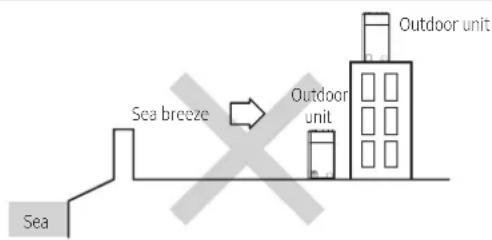
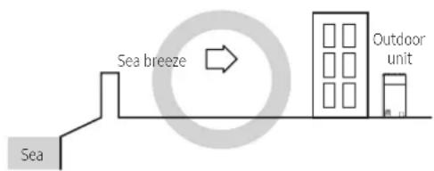
Installation Guide at the seashore
Make sure to follow below guides when installing at the seashore.
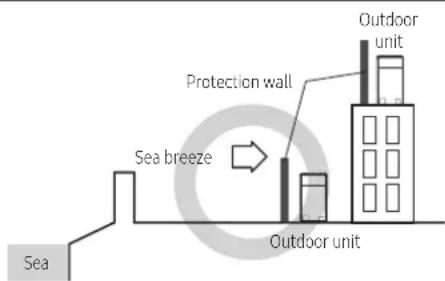
1 Do not install the product in a place where it is directly exposed to sea water and sea breeze.
- Make sure to install the product behind a structure (such as building) that can block see breeze.
- Even when it is inevitable to install the product in seashore, make sure that product is not directly exposed to sea breeze by installing a protection wall.
flowchart
graph LR
    A["Sea"] --> B["Sea breeze"]
    B --> C["Protection wall"]
    C --> D["Outdoor unit"]
    D --> E["Outdoor unit"]
Protection wall should be constructed with a solid material that can block the sea breeze and the height and width of the wall should be 1.5 times larger than the size of the outdoor unit. (You must secure more than 700mm (28inch) of space between the protection wall and the outdoor unit for air circulation.)
※ As we cannot guarantee that the corrosion resistance model(AM***AXVAFCAAZ) can prevent corrosion completely, we recommend that you install a protection wall or install the outdoor unit behind a structure(such as building) that can block sea breeze.
2 Consider that the salinity particles clinging to the external panels should be sufficiently washed out.
3 Because the residual water at the bottom of the outdoor unit significantly promotes corrosion, make sure that the slope does not disturb drainage.
- Keep the floor level so that rain does not accumulate.
- Be careful not to block the drain hole due to foreign substance
4 When product is installed in seashore, periodically clean it with water to remove attached salinity.
5 Make sure to install the product in a place that provides smooth water drainage. Especially, ensure that the base part has good drainage.
6 If the product is damaged during the installation or maintenance, make sure to repair it.
7 Check the condition of the product periodically.
- Check the installation site every 3 months and perform anticorrosion treatment such as R-Pro supplied by SAMSUNG (Code : MOK-220SA) or commercial water repellent grease and wax, etc., based on the product condition.
- When the product is to be shut down for a long period of time, such as off-peak hours, take appropriate measures like covering the product.
8 If the product installed within 500m (1640ft) of seashore, special anti-corrosion treatment is required.
* Please contact your local SAMSUNG representative for further details.
If you cannot find a proper location to install the outdoor unit, consult with an expert or specialty store.
flowchart
graph LR
    A["Sea"] --> B["Sea breeze"]
    B --> C["Outdoor unit"]
    C --> D["Outdoor unit"]
    style C stroke:#000,stroke-width:2px
    style D fill:#f9f,stroke:#333
flowchart
graph LR
    A["Sea"] --> B["Sea breeze"]
    B --> C["Outdoor unit"]
CAUTION
- System air conditioner may cause static noise when listening to AM stations. Therefore, select an installation location for indoor unit where electrical wiring can be done while keeping certain distance from a radio, computer and stereo equipment.
- Especially, keep the unit at least 3m (9.84ft) away from the electrical equipment in an area with weak electromagnetic waves and put the main power cable and communication cables in a separately installed protection tube.
-
Make sure that there is no equipment that generates electromagnetic waves. If not electromagnetic waves may cause problem to the control systems which may lead to air conditioner malfunction. (Example: Remote control sensor of the indoor unit may not receive the signal very well, due to ballast stabilizer of the lighting equipment.)
-
In regions with heavy snowfall, make sure to install the outdoor unit where there is no concerns of direct snowfall on the outdoor unit. Also, build higher base support so that accumulated snow does not block the air inlet or the heat exchanger.
- R-410A refrigerant is a safe, nontoxic and nonflammable refrigerant. However, if the place holds any concerns for exceeding dangerous level of refrigerant concentration in case of refrigerant leakage, extra ventilation system is required.
10 English
- When you install the outdoor unit in high places such as a roof, install fence or guardrail around it. When there is no fence or guardrail, service person could fall.
- Do not install the product in places where corrosive gases such as sulfur oxides, ammonia, and sulfurous gas are produced. (e.g. Toilet outlet, ventilation opening, sewage works, dyeing complex, cattle shed, sulfuric hot spring, nuclear power plant, ship etc.) When installing the product in those places, contact an installation specialty store as the copper pipe and brazing part will need additional corrosion proof or anti-rust additive to prevent corrosion.
- Make sure not to keep any inflammable materials (such as wooden materials, oil etc.) around the outdoor unit. When there's fire, those inflammable material will easily catch the fire and may pass it on to the product.
- Depending on the condition of power supply, unstable power or voltage any cause malfunction of the parts or control system. (At the ship or places using power supply from electric generator...etc)
- Make sure to install MCU when using HR products.
- When you select the location to install the MCU, the location is far away from indoor rooms because the refrigerant running of MCU may create noise.
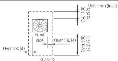
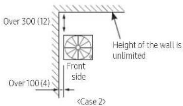
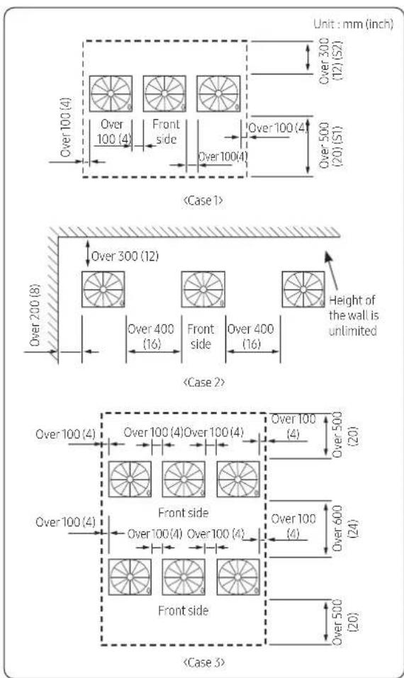
Outdoor unit space requirements
- Space requirement was decided based on following conditions; Cooling mode, outdoor temperature of 35^ C ( 95^ F). Larger space is required if the outdoor temperature is higher than 35^ C ( 95^ F) or if the place is heated easily by quantity of solar radiation.
- When you secure installation space, consider path for people and the direction of the wind.
- Secure installation space as shown in the below illustration, considering ventilation and the service space.
- If the installation space is narrow, installer or other worker may get injured during work and may also cause problem to the product.
- If you install multiple number of outdoor units in one space, make sure to secure enough ventilation space if there's any walls around the product that may disturb the air flow. If enough ventilation space is not secured, product may malfunction.
- You may install the outdoor units with 20mm (0.78inch) of space between the product, but product's performance may decrease depending on the installation environment.
Single installation
Module installation
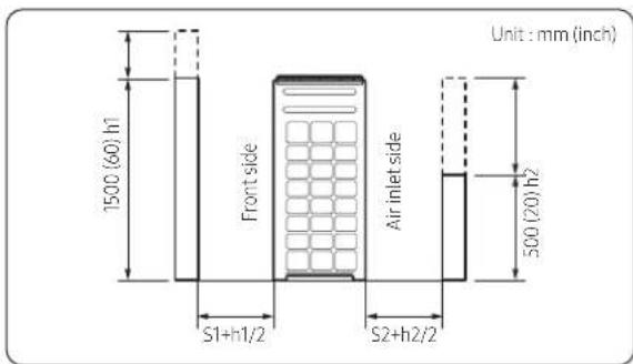
- For
or - Height of the wall on the front side should not be higher than 1500mm (60inch).
- Height of the wall on the air inlet side should not be higher than 500mm (20inch).
- Height of the wall on the side is not limited.
- If the height of the wall exceeds by certain value (h1, h2), additional clearance [(h1)/2, (h2)/2 : Half of the exceeded height] should be added to the service space (S1, S2).
English 11
Preparing materials and tools
- You must keep the installation manual until the installation is finished.
- Hand over the installation manual to the customer after finishing the installation.
| Installation manual (1) Packing socket (1) | |
※ Certain models are supplied with a packing socket. The socket type may differ, depending on the model.
Optional accessories
- Following optional accessories are needed for connecting pipes between the indoor and outdoor units.
| Classification Model Name | Specification | |
| MBH kW | ||
| Y-Joint | MXJ-YA1509M 51 and below 15.0 and below | |
| MXJ-YA2512M 52-136 15.1 ~40.0 | ||
| MXJ-YA2812M 137-154 40.1 -45.0 | ||
| MXJ-YA2815M 155-240 45.1 ~70.3 | ||
| MXJ-YA3419M 241~336 70.4 ~98.4 | ||
| MXJ-YA4119M 337-461 98.5 ~135.2 | ||
| MXJ-YA4422M Over 461 Over 135.2 | ||
| Classification Model Name | Specification | ||
| MBH kW | |||
| Y-Joint(Only H/R) | MXJ-YA1500M | 76 and below 22 | 4 and below |
| MXJ-YA2500M | 77-240 | 22.5 -70.3 | |
| MXJ-YA3100M 2 | 41~461 | 70.4 ~135.2 | |
| MXJ-YA3800M | Over 461 | Over135.2 | |
| Distributionheader | MXJ-HA2512M | 154 and below(for 4 rooms) | 45.0 and below(for 4 rooms) |
| MXJ-HA3115M | 240 and below(for 8 rooms) | 70.3 and below(for 8 rooms) | |
| MXJ-HA3819M | 241 ~ 461(for 8 rooms) | 70.4 ~ 135.2(for 8 rooms) | |
| Y-Joint-Outdoor unit | MXJ-TA3819M | 461 and below | 135.2 andbelow |
| MXJ-TA4422M | Over 461 | Over135.2 | |
| Y-Joint(Only H/R)-Outdoor unit | MXJ-TA3100M | 461 and below | 135.2 andbelow |
| MXJ-TA3800M | Over 461 | Over135.2 | |
※ If you use an indoor unit with no internal EEV(Electric Expansion Valve), you will need an EEV kit.
※ Only use the genuine accessories listed in above table and do not use imitated accessories.
Outdoor unit installation
WARNING
- Make sure to remove the wooden pallet before installing the outdoor unit. If you do not remove the wooden pallet, there is risk of fire during welding the pipes. If the outdoor unit is installed with wooden pallet on, and it was used for long period time, wooden palette may break and cause electrical hazard or high pressure may damage the pipes.
※ Fix an outdoor unit firmly on the base ground with anchor bolts.
※ Manufacturer is not responsible for the damage occurred by not following the installation standards.
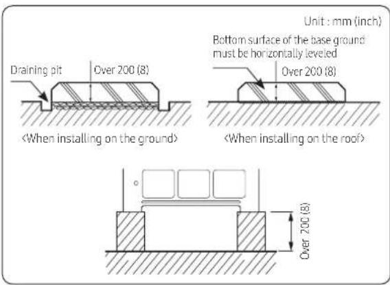
1 Make sure that the height of the base ground is 200mm (8inch) or higher to protect the outdoor unit from rain water or other external conditions. Also, install a draining pit around the base ground and connect the drain pipe to the drainage.
2 Considering the vibration and weight of the outdoor unit, strength of the base ground must be strong to prevent noise and the top surface of it should be flat.
3 Base ground should be 1.5 times larger than the bottom of the outdoor unit.
4 Outdoor unit must be fixed firmly so that it can withstand the wind speed of 30m/s. If you cannot fix the outdoor unit on the base ground, fix it by side or use extra structure.
5 In heating operation, defrost water may form so you must really care about the drainage and waterproofing the floor. To prevent defrost water from stagnating or freezing, construct a drainage with over 1/50 slope. (Ice may form on the floor in winter season.)
6 It is necessary to add wire mesh or steel bar during concrete construction for the base ground to prevent damages or cracks.
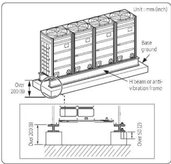
7 When installing multiple outdoor units at the same place, construct an H beam or an anti-vibration frame on the base ground to install the outdoor unit.
8 After installing an H beam or an anti-vibration frame, apply corrosion protection and other necessary coating.
9 When concrete construction for outdoor unit installation is completed, install an anti-vibration pad (t=20mm/0.78inch or more) or an anti-vibration frame to prevent vibration of the outdoor unit from transferring to the base ground.
10 Place the outdoor unit on an H beam or an anti-vibration frame and fix it with the bolt, nut and washer. (The bearing force has to be over 3.5kN)
12 English
Base ground construction
Outdoor unit installation
Outdoor unit base mount and anchor bolt position
![Unit : mm (inch) Outdoor unit - Anti-vibration frame [4/8-Φ12(0.47)] Anti-vibration - Base ground [4-Φ18(0.71)]](/content/2026/05/1065471/images/294239a144274d5fd73dfe9aac82a48ed46a1d95e401d373412959383f752f4c.jpg)
Unit: mm (inch)
| Classification | DVM S2 Small type | DVM S2 Large type | DVM S2 X-Large type |
| A 930 (36.6) | 1295 (51) 1860 (73.2) | ||
| B 790 (31.1) | 1155 (45.5) 1720 (67.7) | ||
| C -- 150 (5.9) |
※ Refer to the blueprints in technical data book to make a holes for connecting the anti-vibration pad.
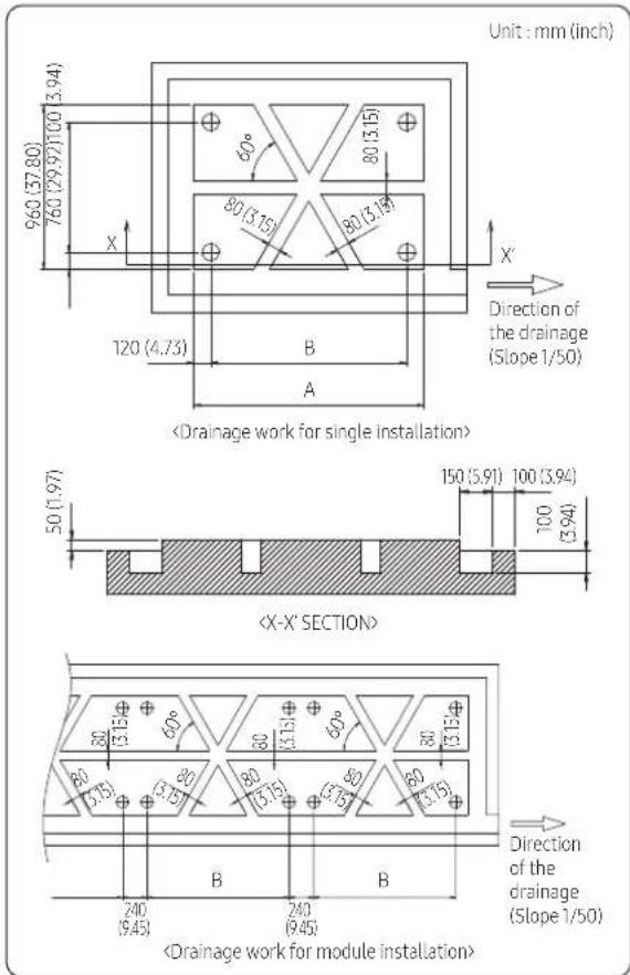
Examples of draining work
- Construct the drainage ditch with reinforced concretes and make sure that water-proofing work is done.
- For smooth draining of defrost water, make sure to apply 1/50 slope.
- Construct a drainage around the outdoor unit to prevent the defrost water (from the outdoor unit) from stagnating, overflowing or freezing near the installation space.
- When the outdoor unit is installed on the roof, check the strength and waterproof status of the roof.
Unit : mm (inch)
| Classification | DVM S2 Small type | DVM S2 Large type | DVM S2 X-Large type |
| A | 1030 (40.6) | 1395 (54.9) | 1960 (77.2) |
| B 790 (31.1) | 1155 (45.5) | 1720 (67.7) |
English 13
Outdoor unit installation

CAUTION
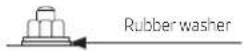
- Cautions regarding on connecting the anchor bolt - Tighten the rubber washer to prevent the bolt connection part of the outdoor unit from corroding.
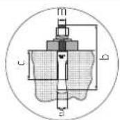
- Anchor specification
| Size | Diameter of drill bit (a) | Anchor length (b) | Sleeve length (c) | Insert depth | Fastening torque |
| 10 | 14mm(1/2") | 75mm(3") | 40mm(1-1/2") | 50mm(2") | 30 N·m |
※ Use the anchor bolts and nuts that is zinc plated or made of STS material. Regular anchor bolts or nuts may get damaged by corrosion.
• Cautions regarding on connecting the pipe
- If you install the outdoor unit on the rooftop, check the strength and make sure to waterproof the rooftop.
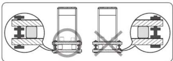
- Construct draining pit around the base construction and pay attention to the drainage around the outdoor unit. (Condensation or defrost water may form during outdoor unit operation.)
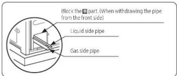
- If there's any possibility of small animals from entering the pipe outlet, block the outlet as shown in the illustration.
- Cautions regarding on anti-vibration frame installation
- During installation, make sure there is no gap between the base ground and the supporting structures such as anti-vibration frame or H beam.
- Base ground must be constructed strongly to support the bottom part of the anti-vibration mount.
natural_image
Technical diagram showing mechanical assembly with cross-sectional views and no visible text or symbols- After installing the anti-vibration frame, untighten the fixing part on the top and bottom part of the frame.
- Caution for installing discharge duct
- Static pressure of the discharge duct should be within the standard specification when installing the duct.
- If you remove the fan guard to install the discharge duct, make sure to install a safety net on the duct outlet. Foreign substance may enter into the product and there could be a risk of personal injury.
- Wear protection equipment at all times when making galvanized sheet metal duct, since the worker may get injured by the sharp parts.
- When installing the outdoor unit under the tree or near forest, leafs may get into the product and cause problems on the product. Therefore, install a discharge duct to prevent foreign substance infiltration.
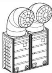
natural_image
Illustration of two industrial ventilation units with fans and heat sinks (no text or symbols)(Preventing foreign substance infiltration)
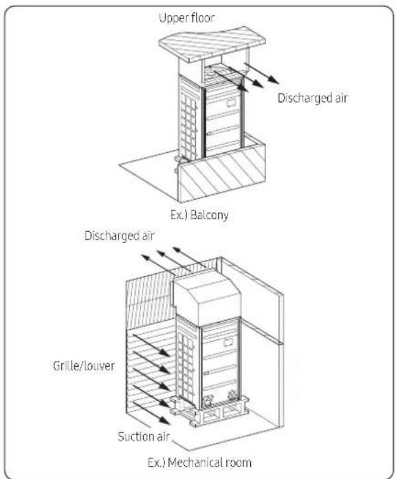
Installing the outdoor unit in various environments
Installing the outdoor unit around the obstacles
- It is necessary to install a discharge guide duct(field supply) to direct exhaust from the fan horizontally, when it is difficult to provide a minimum space of 2m (6.56ft) between the air outlet and a nearby obstacle.
14 English

WARNING
- Should adopt bar type louver. Don't use a type of rain resistance louver.
[Bar type louver] [Rain resistance louver]
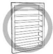
- Louver specifications.
- Angle criteria: less than 20^
- Opening ratio criteria: greater than 80%
Installing the outdoor unit in cold region
- In cold regions with lots of snowfall, install a snow prevention duct, as a sufficient countermeasure, to prevent snow from accumulating on the outdoor unit. When the snow prevention duct is not installed, frost may accumulate on the heat exchanger and heating operation may not work normally.
• Air outlet of the duct should not be directed to the enclosed space.

CAUTION
- Cautions regarding on installing the frame and selecting the base ground
- Height (h) of the frame and the base ground should be higher than the "heaviest expected snowfall".
– Area of the frame and the base ground should not be larger than the are of the outdoor unit. Snow may accumulate if the area of the frame or the base ground is larger.
natural_image
Technical line drawing of two industrial equipment units with no visible text or symbolsInstalling the outdoor unit in windy region
- In windy regions such as near sea shores, protection wall or wind protection duct must be installed for normal operation of the outdoor unit. (Refer to the illustration of the snow prevention duct, for installing the wind protection duct.)
- Install the wind prevention duct with the consideration of major wind direction. If the direction of the discharge part is same as major direction of the wind, it could cause product's performance decrease.

CAUTION
- Cautions regarding on installing the frame and selecting the base ground
- The base ground must be solid and the outdoor unit must be fixed with anchor bolts.
- Make sure to install outdoor unit in a place strong enough to withstand its weight. If the place cannot withstand the weight of the outdoor unit, outdoor unit may fall and cause personal injury.
- When installing on a rooftop subject to strong wind, countermeasures must be taken to prevent the unit from falling down.
- Use a frame that is resistant to corrosion.
English 15
Outdoor unit installation
Refrigerant pipe installation

WARNING
- When installing, make sure there is no leakage. When collecting the refrigerant, stop the compressor first before removing the connection pipe. If the refrigerant pipe is not properly connected and the compressor works with the service valve open, the pipe inhales the air and it makes the pressure inside of the refrigerant cycle abnormally high which may lead to explosion and injury.
Refrigerant pipe work
- The length of refrigerant pipe should be as short as possible and the height difference between an indoor and outdoor unit should be minimized.
- Piping work must be done within allowable piping length, height difference, and the allowable length after branching.
- The pressure of the R-410A is high. Use only certified refrigerant pipe and follow the installation method.
- After installing the pipes, calculate the total length of the pipe to check if additional refrigerant is needed. When you need to charge the additional refrigerant, make sure to use R-410A refrigerant.
- Use clean refrigerant pipe and there shouldn't be any harmful ion, oxide, dust, iron content or moisture inside pipe.
- Use tools and accessories that fit on R-410A only.
| Tool | Installation process/purpose | Compatibility with conventional tool | |
| Pipe cutter | pe flaring | Pipe cutting | Compatible |
| Flaring tool P | |||
| Refrigerant machine oil | Refrigerant pipe installation | Apply refrigerant oil on flared part | Exclusive ether oil, ester oil, alkali benzene oil or synthetic oil |
| Torque wrench | Connect flare nut with pipe | Compatible | |
| Pipe bender | Pipe bending | ||
| Nitrogen gas | Air tightness test | Prevent oxidation within the pipe | |
| Welder | Pipe welding | ||
| Manifold gage | Air tightness test ~ additional refrigerant charging | Vacuuming, charging refrigerant and checking operation | Compatible |
| Refrigerant charging hose | Need exclusive one since there is risk of refrigerant leakage or inflow of impurities | ||
| Tool | Installation process/purpose | Compatibility with conventional tool |
| Vacuum pump | Pipe drying | Compatible (Use products which contain the check valve to prevent the oil from flowing backward into the outdoor unit.) Use the one that can be vacuumed up to -100.7kpa(5Torr). |
| Scale for refrigerant charging | Refrigerant charging Compatible | |
| Gas leak detector | Gas leak test | Need exclusive one (Ones used for R-134a is compatible) |
| Flare nut Must use the flare nut equipped with the product. | ||
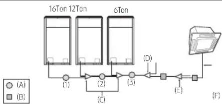
Selecting refrigerant pipe
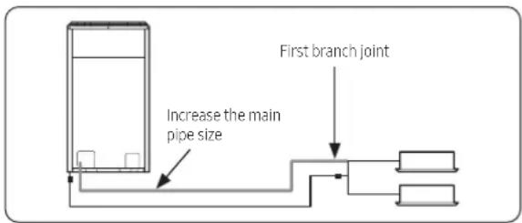
• Install the refrigerant pipe according to main pipe size of each outdoor unit capacity.
- When the pipe length (including elbow) between an outdoor unit and the farthest indoor unit exceeds 90m, you must increase the size of the pipe (main pipe) by one grade which connects between the outdoor unit to the first branch joint.
- For H/R model, When the pipe length (including elbow) between an outdoor unit and the farthest indoor unit exceeds 90m, you must increase the size of the liquid pipe by one grade among the pipes(main pipe) which connects between the outdoor unit to the first branch joint.
English 17
Refrigerant pipe installation
flowchart
graph TD
    A["16Ton"] --> B["(1)"]
    C["12Ton"] --> D["(2)"]
    E["6Ton"] --> F["(3)"]
    G["Control Unit"] --> H["(E)"]
    I["(F)"] --> J["(F)"]
Size of the pipe connected to the outdoor unit (A) Branch joint (C+E)
Select the size of the main pipe according to the below table.
| Outdoor unit capacity (MBH) (Cooling) | Outdoor unit capacity (kW) (Cooling) | *Maximum pipe length within 295ft (90m) | *Maximum pipe length over 295ft (90m) | ||||||
| Liquid Gas | Liquid Gas | ||||||||
| inch mm inch | inch mm inch | inch | mm | ||||||
| Capacity ≤ 85 | Capacity ≤ 25 | ∅3/8 | ∅9.52 | ∅3/4 | ∅19.05 | ∅1/2 | ∅12.70 | ∅7/8 | ∅22.22 |
| 85 < Capacity ≤ 99 | 25 < Capacity ≤ 29 | ∅7/8 | ∅22.22 | ∅1 non=0 | ∅25.40 non=0 | ||||
| 99 < Capacity ≤ 120 | 29 < Capacity ≤ 35 | ∅1/2 | ∅12.70 | ∅11/8 | ∅28.58 | ∅5/8 | ∅15.88 | ∅11/8 | ∅28.58 |
| 120 < Capacity ≤ 140 | 35 < Capacity ≤ 41 | ||||||||
| 140 < Capacity ≤ 160 | 41 < Capacity ≤ 47 | ∅5/8 | ∅15.88 | ∅11/4 non=0 | ∅31.75 non=0 | ||||
| 160 < Capacity ≤ 181 | 47 < Capacity ≤ 53 | ∅3/4 | ∅19.05 | ||||||
| 181 < Capacity ≤ 222 | 53 < Capacity ≤ 65 | ||||||||
| 222 < Capacity ≤ 240 | 65 < Capacity ≤ 70 | ∅1 3/8 | ∅34.92 | ∅1 3/8 | ∅34.92 | ||||
| 240 < Capacity ≤ 336 | 70 < Capacity ≤ 98 | ∅3/4 | ∅19.05 | ∅7/8 | ∅22.22 | ∅11/2 non=0 | ∅38.10 non=0 | ||
| 336 < Capacity ≤ 467 | 98 < Capacity ≤ 137 | ∅1 5/8 | ∅41.28 | ∅1 5/8 | ∅41.28 | ||||
| 467 < Capacity ≤ 583 | 137 < Capacity ≤ 171 | ||||||||
*Maximum pipe length: The pipe length between an outdoor unit and the farthest indoor unit. Note1) If 1^ (25.40mm) pipe is not available on site, use 1 1/8^ (28.58mm) pipe.
Note2) If ∅11/4" (31.75mm) pipe is not available on site, use ∅1 3/8" (34.92mm) pipe.
Note3) If ∅11/2" (39.10mm) pipe is not available on site, use ∅1 5/8" (41.28mm) pipe.
For the case that the diameter of the default pipe of an outdoor unit does not match that of the pipe installed on the site, a socket is provided by default together with the outdoor unit.
Size of the pipe between branch joints (B)
Select the pipe size according to the sum of indoor unit capacity which will be connected after the branch.
※ However, if the size of the pipe between branch joints (B) is bigger than the size of the pipe connected to the outdoor unit (A), apply the pipe size (A).
| Indoor unit capacity (MBH) | Indoor unit capacity (kW) | Branch pipe length within 148ft (45m) | Branch pipe length between 148ft~295ft (45~90m) | ||||||
| Liquid Gas Liquid Gas | |||||||||
| inch | mm | inch | mm | inch | mm | inch | mm | ||
| Capacity<19 | Capacity <5.7 | ∅1.4 | ∅6.35 | ∅1.2 | ∅12.70 | ∅3.8 | ∅9.52 | ∅5.8 | ∅15.88 |
| 19 ≤ Capacity <55 | 5.7 ≤ Capacity <16 | ∅3.8 | ∅9.52 | ∅5.8 | ∅15.88 | ∅1.2 | ∅12.70 | ∅3.4 | ∅19.05 |
| 55 ≤ Capacity <79 | 16 ≤ Capacity <23.2 | ∅3.4 | ∅19.05 | ∅7.8 | ∅22.22 | ||||
| 79 ≤ Capacity <115 | 23.2 ≤ Capacity <33.6 | ∅7.8 | ∅22.22 | ∅1 mm=0 | ∅25.40 mm=0 | ||||
| 115 ≤ Capacity <133 | 33.6 ≤ Capacity <39 | ∅1.2 | ∅12.70 | ∅11.8 | ∅28.58 | ∅5.8 | ∅15.88 | ∅11.8 | ∅28.58 |
| 133 ≤ Capacity <150 | 39 ≤ Capacity <44 | ∅11.4 mm=0 | ∅31.75 mm=0 | ||||||
| 150 ≤ Capacity <172 | 44 ≤ Capacity <50.4 | ||||||||
| 172 ≤ Capacity <229 | 50.4 ≤ Capacity <67.2 | ∅5.8 | ∅15.88 | ∅3.4 | ∅19.05 | ∅13.8 | ∅34.92 | ||
| 230 ≤ Capacity <248 | 67.2 ≤ Capacity <72.8 | ∅15.8 | ∅34.92 | ∅17.7 mm=0 | ∅58.10 mm=0 | ||||
| 248 ≤ Capacity <344 | 72.8 ≤ Capacity <100.8 | ∅3.4 | ∅19.05 | ∅7.8 | ∅22.22 | ∅15.8 | ∅41.28 | ||
| 344 ≤ Capacity <392 | 100.8 ≤ Capacity <115 | ∅15.8 | ∅41.28 | ∅13.4 mm=0 | ∅44.45 mm=0 | ||||
| 392 ≤ Capacity <592 | 115 ≤ Capacity <173.6 | ||||||||
| 592 ≤ Capacity <676 | 173.6 ≤ Capacity <198 | ∅7.8 | ∅22.22 | ∅13.4 mm=0 | ∅44.45 mm=0 | ∅1 mm=0 | ∅25.40 mm=0 | ∅21.8 | ∅53.98 |
| 676 ≤ Capacity <860 | 198 ≤ Capacity <252 | ∅21.8 | ∅53.98 | ||||||
| 860 ≤ Capacity | 252 ≤ Capacity | ∅1 mm=0 | ∅25.40 mm=0 | ∅11.8 | ∅78.58 | ||||
Note1) If ∅1" (25.40mm) pipe is not available on site, use ∅1 1/8" (28.58mm) pipe.
Note2) If ∅11/4" (31.75mm) pipe is not available on site, use ∅1 3/8" (34.92mm) pipe.
Note3) If ∅11/2" (38.10mm) pipe is not available on site, use ∅1 5/8" (41.28mm) pipe.
Note4) If 01 3/4" (44.45mm) pipe is not available on site, use 02 1/8" (53.98mm) pipe.
Ex.) 34 Ton
| Ton No. | Pipe size (O.D) | ||||
| Liquid pipe Gas pipe | |||||
| mm inch | mm inch | ||||
| 16 (1) | 15.88 5/8 | 28.58 | 11/8 | ||
| 28 (2) | 19.05 3/4 | 34.92 | 15/8 | ||
| 34 (3) | 19.05 3/4 | 41.28 | 15/8 | ||
Branch joint between outdoor units (C)
Select a branch joint according to the sum of the capacity of outdoor units connected to the branch joint.
| Classification | Outdoor unit capacity | Model name | |
| MBH | kW | ||
| Y-joint for outdoor unit (C) | Capacity ≤ 467 | Capacity ≤ 137 | MXJ-TA3819M |
| 467 < Capacity | 137 < Capacity | MXJ-TA4422M | |
First branch joint (D)
Select according to the sum of the capacity of the outdoor unit.
| Classification | Outdoor unit capacity | Model name | |
| MBH | kW | ||
| Y-joint (D) | Capacity ≤ 140 | Capacity ≤ 41 | MXJ-YA2512M |
| Capacity ≤ 160 | Capacity ≤ 47 | MXJ-YA2812M | |
| Capacity ≤ 239 | Capacity ≤ 70 | MXJ-YA2815M | |
| Capacity ≤ 336 | Capacity ≤ 98 | MXJ-YA3419M | |
| Capacity ≤ 467 | Capacity ≤ 137 | MXJ-YA4119M | |
| 467 < Capacity | 137 < Capacity | MXJ-YA4422M | |
Branch joint (E)
Select a branch joint according to the sum of indoor unit capacity which will be connected after the branch.
※ However, if the branch joints (E) is bigger than the first branch joint (D), apply the branch joint of the same size as the first branch joint (D).
| Classification | Indoor unit capacity | Model name | |
| MBH | kW | ||
| Y-joint (E) | Capacity < 55 | Capacity < 16 | MXJ-YA1509M |
| 55 ≤ Capacity < 133 | 16 ≤ Capacity < 39 | MXJ-YA2512M | |
| 133 ≤ Capacity < 172 | 39 ≤ Capacity < 50.4 | MXJ-YA2812M | |
| 172 ≤ Capacity < 248 | 50.4 ≤ Capacity < 72.8 | MXJ-YA2815M | |
| 248 ≤ Capacity < 344 | 72.8 ≤ Capacity < 100.8 | MXJ-YA3419M | |
| 344 ≤ Capacity < 478 | 100.8 ≤ Capacity < 140 | MXJ-YA4119M | |
| 478 < Capacity | 140 < Capacity | MXJ-YA4422M | |
| Distribution header (E) | Capacity < 172 (for 4 rooms) | Capacity < 50.4 (for 4 rooms) | MXJ-HA2512M |
| Capacity < 248 (for 8 rooms) | Capacity < 72.8 (for 8 rooms) | MXJ-HA3115M | |
| Capacity < 478 (for 8 rooms) | Capacity < 140 (for 8 rooms) | MXJ-HA3819M | |
Size of the pipe between the branch joint and the indoor unit (F)
Select according to the capacity of the indoor unit.
| Indoor unit capacity | Liquid | Gas | |||
| MBH | kW | inch | mm | inch | mm |
| Capacity ≤ 20 | Capacity ≤ 6 | 1/4 | 6.35 | 1/2 | 12.7 |
| 20 < Capacity ≤ 54 | 6 < Capacity ≤ 16 | 3/8 | 9.52 | 5/8 | 15.88 |
| 54 < Capacity ≤ 78 | 16 < Capacity ≤ 23 | 3/8 | 9.52 | 3/4 | 19.05 |
| 78 < Capacity | 23 < Capacity | 3/8 | 9.52 | 7/8 | 22.22 |
* If the criteria for selecting the branch in the outdoor installation manual and the branch installation manual are different, please select the branch in accordance with the outdoor installation manual.
When all the following conditions are met, install the main liquid pipe that is one step smaller to reduce piping load and the amount of refrigerant.
Note that the refrigerant for the main liquid pipe must be added by the specified amount upon reduction.
Condition 1: The vertical piping length is less than 131 ft (40 m)
Condition 2: For BG units, allowable length A (ft) ≥ max. piping length (ft) / {1 - (vertical piping length (ft) * 0.0046)}
* Max. piping length: The equivalent length (ft) of piping from the outdoor unit to the farthest indoor unit
For SI units, allowable length A (m) ≥ max. piping length (m) / {1 - (vertical piping length (m) * 0.015)}
※ Max. piping length: The equivalent length (m) of piping from the outdoor unit to the farthest indoor unit
※ If the conditions above are satisfied and one-size smaller piping has been installed, set the "liquid pipe (main pipe) size reduction" option.
- Length allowed to reduce the diameter of liquid pipe, A (equivalent length)
| Capacity (HP) | Below 90 m Over 90m | |||||||
| Pipe diameter | Max length (m) | Pipe diameter | Max length (m) | |||||
| mm | inch | m | ft | mm | inch | m | ft | |
| 8 | This capacity is not supported. | |||||||
| 10 | This capacity is not supported. | |||||||
| 12 | 9.52 | 3/8 | 50 | 164 | 12.7 | 1/2 | 200 | 656 |
| 14 | 9.52 | 3/8 | 40 | 131 | 12.7 | 1/2 | 190 | 623 |
| 16 | 9.52 | 3/8 | 30 | 98 | 12.7 | 1/2 | 150 | 492 |
| 18 | 12.7 | 1/2 | 90 | 298 | 15.88 | 5/8 | 200 | 656 |
| 20 | 12.7 | 1/2 | 90 | 298 | 15.88 | 5/8 | 200 | 656 |
| 22 | 12.7 | 1/2 | 80 | 262 | 15.88 | 5/8 | 200 | 656 |
| 24 | 12.7 | 1/2 | 70 | 230 | 15.88 | 5/8 | 200 | 656 |
| 26 | 15.88 | 5/8 | 90 | 295 | 19.05 | 3/4 | 200 | 656 |
| 28 | 15.88 | 5/8 | 90 | 295 | 19.05 | 3/4 | 200 | 656 |
| 30 | 15.88 | 5/8 | 90 | 295 | 19.05 | 3/4 | 200 | 656 |
| 32 | 15.88 | 5/8 | 90 | 295 | 19.05 | 3/4 | 200 | 656 |
| 34 | 15.88 | 5/8 | 90 | 295 | 19.05 | 3/4 | 200 | 656 |
| 36 | 15.88 | 5/8 | 90 | 295 | 19.05 | 3/4 | 200 | 656 |
| 38 | 15.88 | 5/8 | 90 | 295 | 19.05 | 3/4 | 200 | 656 |
| 40 | 15.88 | 5/8 | 80 | 262 | 19.05 | 3/4 | 200 | 656 |
| 42 | 15.88 | 5/8 | 70 | 230 | 19.05 | 3/4 | 200 | 656 |
| 44 | 15.88 | 5/8 | 70 | 230 | 19.05 | 3/4 | 200 | 656 |
| 46 | 15.88 | 5/8 | 60 | 197 | 19.05 | 3/4 | 180 | 591 |
| 48 | 15.88 | 5/8 | 60 | 197 | 19.05 | 3/4 | 170 | 558 |
| 50 | 15.88 | 5/8 | 50 | 164 | 19.05 | 3/4 | 150 | 492 |
| 52 | 15.88 | 5/8 | 50 | 164 | 19.05 | 3/4 | 140 | 459 |
| Capacity (HP) | Below 90 m Over 90m | |||||||
| Pipe diameter | Max length (m) | Pipe diameter | Max length (m) | |||||
| mm | inch | m | ft | mm | inch | m | ft | |
| 54 | 15.88 | 5/8 | 40 | 131 | 19.05 | 3/4 | 130 | 427 |
| 56 | 15.88 | 5/8 | 40 | 131 | 19.05 | 3/4 | 120 | 394 |
| 58 | 15.88 | 5/8 | 40 | 131 | 19.05 | 3/4 | 120 | 394 |
| 60 | 15.88 | 5/8 | 40 | 131 | 19.05 | 3/4 | 110 | 361 |
| 62 | 19.05 | 3/4 | 90 | 295 | 22.22 | 7/8 | 200 | 656 |
| 64 | 19.05 | 3/4 | 90 | 295 | 22.22 | 7/8 | 200 | 656 |
| 66 | 19.05 | 3/4 | 90 | 295 | 22.22 | 7/8 | 200 | 656 |
| 68 | 19.05 | 3/4 | 90 | 295 | 22.22 | 7/8 | 200 | 656 |
| 70 | 19.05 | 3/4 | 80 | 262 | 22.22 | 7/8 | 190 | 623 |
| 72 | 19.05 | 3/4 | 80 | 262 | 22.22 | 7/8 | 180 | 591 |
| 74 | 19.05 | 3/4 | 70 | 230 | 22.22 | 7/8 | 170 | 558 |
| 76 | 19.05 | 3/4 | 70 | 230 | 22.22 | 7/8 | 160 | 525 |
| 78 | 19.05 | 3/4 | 70 | 230 | 22.22 | 7/8 | 150 | 492 |
| 80 | 19.05 | 3/4 | 60 | 197 | 22.22 | 7/8 | 150 | 492 |
| 82 | 19.05 | 3/4 | 60 | 197 | 22.22 | 7/8 | 140 | 459 |
| 84 | 19.05 | 3/4 | 60 | 197 | 22.22 | 7/8 | 130 | 427 |
| 86 | 19.05 | 3/4 | 50 | 164 | 22.22 | 7/8 | 130 | 427 |
| 88 | 19.05 | 3/4 | 50 | 164 | 22.22 | 7/8 | 120 | 394 |
| 90 | 19.05 | 3/4 | 50 | 164 | 22.22 | 7/8 | 120 | 394 |
| 92 | This capacity is not supported. | |||||||
| 94 | This capacity is not supported. | |||||||
| 96 | This capacity is not supported. | |||||||
| 98 | This capacity is not supported. | |||||||
E.g. 1: For a site with 18 tons (BG units), max. piping length of 460 ft (395 ft-long horizontal piping and 65 ft-long vertical piping) condition, allowable length A ≥ max. piping length / {1 - (vertical piping length * 0.0046)}
656ft ≥ 460ft / {1 - (65 * 0.0046)} = 460ft / 0.701 = 656ft
Accordingly, the max. piping length of 460 ft (395 ft-long horizontal piping and 65 ft-long vertical piping) is allowable.
E.g. 2: For a site with 18 tons (SI units), max. piping length of 140 m (120 m-long horizontal piping and 20 m-long vertical piping) condition, allowable length A ≥ max. piping length / {1 - (vertical piping length * 0.015)}
200m ≥ 140m / {1 - (20 * 0.015)} = 140m / 0.7 = 200m
Accordingly, the max. piping length of 140m (120m-long horizontal piping and 20m-long vertical piping) is allowable.
English 19
Refrigerant pipe installation
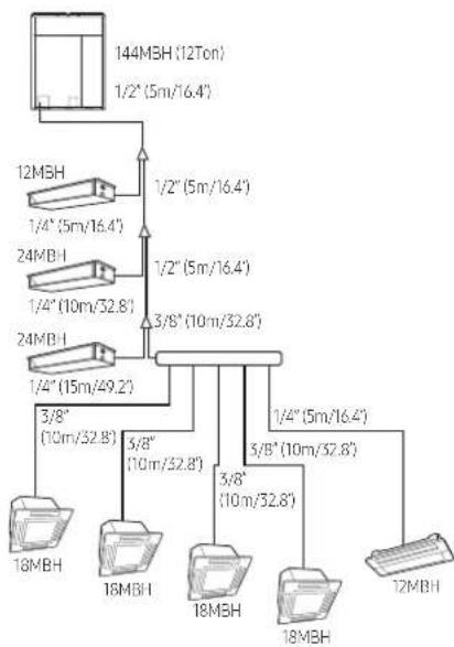
Additional refrigerant
flowchart
graph TD
    A["144MBH (12Ton)\n1/2" (5m/16.4')"] --> B["12MBH"]
    B --> C["1/4" (5m/16.4)"]
    B --> D["24MBH"]
    D --> E["1/4" (10m/32.8)"]
    D --> F["24MBH"]
    F --> G["1/4" (15m/49.2)"]
    G --> H["18MBH"]
    G --> I["18MBH I"]
    G --> J["18MBH"]
    G --> K["18MBH"]
    G --> L["12MBH"]
    B --> M["1/2" (5m/16.4)"]
    D --> N["1/2" (5m/16.4)"]
    F --> O["3/8" (10m/32.8)"]
    G --> P["3/8" (10m/32.8)"]
    H --> Q["1/4" (5m/16.4)"]
    I --> R["3/8" (10m/32.8)"]
    J --> S["3/8" (10m/32.8)"]
    K --> T["3/8" (10m/32.8)"]
    L --> U["12MBH"]
Refrigerant pipe installation
- Basic amount of refrigerant within the outdoor unit [lb(kg)]
- Amount of additional refrigerant has to be calculated based on the sum of all liquid pipe length.
| Classification AM080CXVAFH AM100CXVAFH AM120CXVAFH AM140CXVAFH AM160CXVAFH AM200CXVAFH AM220CXVAFH | ||||||||
| Basic amount [lb(kg)] | 15.4 (7.0) | 15.4 (7.0) | 15.4 (7.0) | 17.6 (8.0) | 17.6 (8.0) | 23.1 (10.5) | 23.1 (10.5) | 23.1 (10.5) |
| Classification AM240CXVAFH AM260CXVAFH AM080CXVAFC AM100CXVAFC AM120CXVAFC AM140CXVAFC AM160CXVAFC AM180CXVAFC | ||||||||
| Basic amount [lb(kg)] | 30.9 (14.0) | 30.9 (14.0) | 15.4 (7.0) | 15.4 (7.0) | 15.4 (7.0) | 17.6 (8.0) | 17.6 (8.0) | 23.1 (10.5) |
| Classification | AM200CXVAFC | AM220CXVAFC | AM240CXVAFC | AM260CXVAFC | AM080CXVAJH | AM100CXVAJH | AM120CXVAJH | AM140CXVAJH |
| Basic amount [lb(kg)] | 23.1 (10.5) | 23.1 (10.5) | 24.3 (11.0) | 24.3 (11.0) | 15.4 (7.0) | 15.4 (7.0) | 15.4 (7.0) | 17.6 (8.0) |
| Classification | AM160CXVAJH | AM180CXVAJH | AM200CXVAJH | AM220CXVAJH | AM240CXVAJH | AM260CXVAJH | AM280CXVAJH | AM300CXVAJH |
| Basic amount [lb(kg)] | 17.6 (8.0) | 23.1 (10.5) | 23.1 (10.5) | 23.1 (10.5) | 30.9 (14.0) | 30.9 (14.0) | 30.9 (14.0) | 34.2 (15.5) |
| Classification | AM320CXVAJH | AM340CXVAJH | AM080CXVAJC | AM100CXVAJC | AM120CXVAJC | AM140CXVAJC | AM160CXVAJC | AM180CXVAJC |
| Basic amount [lb(kg)] | 34.2 (15.5) | 34.2 (15.5) | 13.7 (6.2) | 15.4 (7.0) | 15.4 (7.0) | 17.6 (8.0) | 17.6 (8.0) | 23.1 (10.5) |
| Classification | AM200CXVAJC | AM220CXVAJC | AM240CXVAJC | AM260CXVAJC | AM280CXVAJC | AM300CXVAJC | AM320CXVAJC | AM340CXVAJC |
| Basic amount [lb(kg)] | 23.1 (10.5) | 23.1 (10.5) | 24.3 (11.0) | 24.3 (11.0) | 24.3 (11.0) | 24.3 (11.0) | 27.6 (12.5) | 27.6 (12.5) |
- Amount of additional refrigerant depending on the pipe size (a)
- Amount of additional refrigerant has to be calculated based on the sum of all liquid pipe length.
| Size of liquid pipe[mm (Inch)] | 1/4 ( 6.35 ) | 3/8 ( 9.52 ) | 1/2 ( 12.7 ) | 5/8 ( 15.88 ) | 3/4 ( 19.05 ) | 7/8 ( 22.22 ) | 1 ( 25.4 ) | 1 1/8 ( 28.58 ) |
| Additional amount[lb/ft (kg/m)] | 0.013(0.02) | 0.04(0.06) | 0.084(0.125) | 0.121(0.18) | 0.181(0.27) | 0.235(0.35) | 0.356(0.53) | 0.437(0.65) |
| Amount of refrigerantadded when the diameterof liquid pipe is reduced[kg/m (lb/ft)] | - | 0.054(0.08) | 0.087(0.13) | 0.131(0.195) | 0.188(0.28) | 0.282(0.42) | 0.356(0.53) | - |
- For the indoor unit already connected to EEV kit, the additional refrigerant charging is 0.0067lb/ft (0.01kg/m) regardless of the pipe size.
- Amount of additional refrigerant for each indoor unit ( ) ^b
Unit : lb(kg)
| Capacity (MBH) Model | 5 | 6 | 7 | 9 | 12 | 15 | 18 | 19 | 20 | 24 | 27 | 28 | 30 | 32 | 36 | 38 | 42 | 48 | 54 | 60 | 72 | 76 | 96 |
| 1way cassette (AM***F(N)N1DCH/** ) | 0.25(0.55) | 0.25(0.55) | 0.25(0.55) | 0.32(0.71) | 0.32(0.71) | ||||||||||||||||||
| 2way cassette (AM****N2DCH/** ) | 0.31(0.68) | 0.47(1.04) | |||||||||||||||||||||
| 4way cassette S (600x600) (AM****NNDCH/** ) | 0.29(0.64) | 0.29(0.64) | 0.29(0.64) | 0.29(0.64) | 0.37(0.82) | 0.37(0.82) | |||||||||||||||||
| 4way cassette S (AM****F(N)N4DCH/** ) | 0.45(0.99) | 0.45(0.99) | 0.45(0.99) | 0.45(0.99) | 0.69(1.52) | 0.69(1.52) | 0.69(1.52) | ||||||||||||||||
| 4way cassette S (AM***JN4D(P)CH/** ) | 0.45(0.99) | 1.00(2.20) | 1.00(2.20) | ||||||||||||||||||||
| 360 cassette (AM***KN4DCH/** ) | 0.45(0.99) | 0.45(0.99) | 0.45(0.99) | 0.45(0.99) | 0.69(1.52) | 0.69(1.52) | 0.69(1.52) | ||||||||||||||||
| Duct S (AM***MNMDCH/** ) | 0.45(0.99) | 0.45(0.99) | 0.45(0.99) | 0.45(0.99) | 0.45(0.99) | ||||||||||||||||||
| Duct S (AM***ANHPKH/** ) | 0.45(0.99) | 0.45(0.99) | 0.45(0.99) | 0.68(1.50) | 0.64(1.85) | 0.64(1.85) | 0.64(1.85) | ||||||||||||||||
| Duct S (AM***MNHDCH/** ) | 0.68(1.50) | 0.68(1.50) | 0.68(1.50) | 0.64(1.85) | 0.64(1.85) | ||||||||||||||||||
| Slim duct (AM***FNLDCH/** ) | 0.35(0.77) | 0.35(0.77) | 0.35(0.77) | 0.45(0.99) | 0.45(0.99) | 0.42(0.93) | 0.42(0.93) | 0.62(1.37) | |||||||||||||||
| Slim duct (with drain pump) (AM***KNLDCH/** ) | 0.35(0.77) | 0.35(0.77) | 0.35(0.77) | 0.45(0.99) | 0.45(0.99) | 0.42(0.93) | 0.42(0.93) | 0.62(1.57) | |||||||||||||||
| MSP duct (AM***FU/K)NMDCH*** (AM***JNHDCH*** ) | 0.37(0.82) | 0.37(0.82) | 0.37(0.82) | 0.37(0.82) | 0.54(1.19) | 0.47(1.04) | 0.47(1.04) | 0.47(1.04) | 0.68(1.50) | 0.68(1.50) | 0.91(2.01) | ||||||||||||
| MSP duct (AM****NMPCH*** ) | 0.37(0.82) | 0.68(1.50) | 0.68(1.50) | 0.68(1.50) | 0.68(1.50) | ||||||||||||||||||
| HSP duct (AM***FNHDCH/** ) | 0.68(1.50) | 0.68(1.50) | 1.18(2.60) | 1.18(2.60) | |||||||||||||||||||
| Big duct (AM***JNHFKH/** ) | 1.15(2.54) | 1.15(2.54) | |||||||||||||||||||||
| OAP duct (AM****NE*CH/** ) | 0.68(1.50) | 1.18(2.60) | 1.18(2.60) |
※ If there is no additional refrigerant value for the indoor unit in the above table, refer to the indoor unit installation manual.
- If AHU kit is included among the indoor units, you must add 0.018kg(0.04lb) of refrigerant for every 1MBH of AHU capacity increase. Note1) In case the capacity conjunction of the Hydro Unit HT exceeds 50 % among the total indoor unit, please don't put the additional refrigerant.
• Method to calculate total amount of additional refrigerant
- Amount of additional refrigerant depending on the pipe length (a)
- Amount of additional refrigerant for each indoor unit (6) = (Amount of additional refrigerant for each connected indoor unit)
※ Refer to the table
- Total amount of additional refrigerant = (a) + (b)
Sum of total amount of additional refrigerant and the basic amount of refrigerant should not exceed 100kg (220lb). If the refrigerant exceeds 100kg (220lb), separate the module so that weight of the refrigerant doesn't exceed 100kg (220lb).
Ex> If the outdoor unit's basic refrigerant amount is 8.7kg (19.1lb), the total amount of additional refrigerant(b) should not exceed 91.3kg (200.9lb).
English 21
Refrigerant pipe installation
• Example of refrigerant calculation for HP models
| Classification | Size of liquid pipe [mm (inch)] | Length [m (ft)] | Unit amount of refrigerant [kg/m (lb/ft)] | Amount of additional refrigerant [kg (lb)] | Total amount of additional refrigerant [kg (lb)] |
| 1 | 2 | 1×2 | Σ(1×2) | ||
| Liquid pipe (a) | ∅6.35 (∅1/4) | 35 (114.8) | 0.02 (0.013) | 0.7 (1.49) | a 5.575 (12.19) |
| ∅9.52 (∅3/8) | 50 (164.0) | 0.06 (0.040) | 3.0 (6.56) | ||
| ∅12.70 (∅1/2) | 15 (49.2) | 0.125 (0.084) | 1.875 (4.13) |
| Classification | Model name of indoor unit | Number of indoor units | Unit amount of refrigerant [kg/EA (lb/EA)] | Amount of additional refrigerant [kg (lb)] | Total amount of additional refrigerant [kg (lb)] |
| 1 | 2 | 1 × 2 | (1 × 2) | ||
| Indoor unit (b) | 4way cassette (AM018RN4DCH) | 4 | 0.57 (1.26) | 2.28 (4.92) | b 3.78 (8.22) |
| LSP duct (AM024FNLDCH) | 2 | 0.45 (0.99) | 0.90 (1.98) | ||
| LSP duct (AM012FNLDCH) | 1 | 0.35 (0.77) | 0.35 (0.77) | ||
| 1way cassette (AM012AN1PCH) | 1 | 0.25 (0.55) | 0.25 (0.55) |
- Total amount of refrigerant (a+b) = 5.575 + 3.78 = 9.355 (kg)
= 12.19 + 8.22 = 20.41 (lb)
Temper grade and minimum thickness of the refrigerant pipe
| Outer diameter Minimum thickness | Temper grade | |||
| mm inch | mm inch | |||
| 6.35 1/4 0 | 70 0.028 | Annealed | ||
| 9.52 3/8 0 | 70 0.028 | |||
| 12.70 1/2 | 0.80 0.031 | |||
| 15.88 5/8 | 1.00 0.039 | |||
| 19.05 3/4 | 0.90 0.035 | Drawn | ||
| 22.22 7/8 | 0.90 0.035 | |||
| 25.40 1 | 1.00 0.039 | |||
| 28.58 | 11/8 | 1.10 | 0.043 | |
| 31.75 | 11/4 | 1.10 | 0.043 | |
| 34.92 1 3/8 | 1.21 | 0.048 | ||
| 38.10 11/2 | 1.35 0.053 | |||
| 41.28 15/8 | 1.43 0.056 | |||
| 44.45 | 13/4 1.60 | 0.063 | ||
| 50.80 | 2 | 2.00 | 0.079 | |
| 53.98 | 21/8 | 2.10 | 0.083 | |
Keeping refrigerant pipe
To prevent foreign materials or water from entering the pipe, storing method and sealing method (especially during installation) is very important. Apply correct sealing method depending on the environment.
| Exposure place | Exposure time | Sealing type |
| Outdoor | Longer than one month | Pipe pinch |
| Shorter than one month | Taping | |
| Indoor | - | Taping |
Refrigerant pipe welding and safety information

CAUTION
- Important information for refrigerant pipe work.
- Make sure there is no moisture inside the pipe.
- Make sure there are no foreign substances and impurities in the pipe.
- Make sure there is no leakage.
- Make sure to follow the instruction when welding or storing the pipe.

CAUTION
- For pipes larger than ∅ 3/4" (∅ 19.05mm), drawn type (C1220T-1/2H or C1220T-H) type copper pipe must be used. If a annealed type (C1220T-O) copper pipe is used, pipe may break due to its low pressure resistance and cause personal injury.
English
Nitrogen flushing welding
- When welding the refrigerant pipes, flush them with nitrogen gas as shown in the picture.
- If you do not perform nitrogen flushing when welding the pipes, oxide may form inside the pipe. It can cause the damage of the important parts such as compressor and valves etc.
- Adjust the flow rate of the nitrogen flushing with a pressure regulator to maintain 0.05 ~m^2 / h (0.54ft²/h) or less.
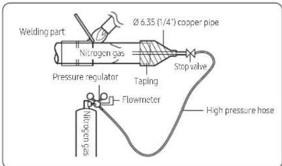
Direction of the pipe when welding
- Direction of the pipe should be headed downward or in a sideways when welding.
- Avoid welding the pipe with pipe direction heading upward.

CAUTION
- When you test gas leakage after welding the pipes, use a designated solution for gas leakage detection. If you use the detection solution that includes sulfuric ingredient, it may cause corrosion to the pipes.
Cutting or flaring the pipes
1 Make sure that you prepared the required tools.
– Pipe cutter, Deburring tool, flaring tool and pipe holder, etc.
2 If you want to shorten the pipe, cut it with a pipe cutter ensuring that the cut edge remains at 90° with the side of the pipe.
- Refer to below illustrations for correct and incorrect examples of cut edges.
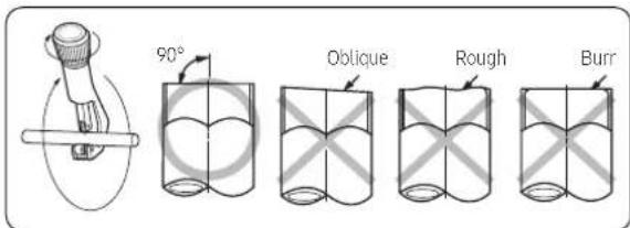
3 To prevent a gas leak, remove all burrs at the cut edge of the pipe using a Deburring tool.
4 Carry out flaring work using flaring tool as shown below.
[Flaring tools]
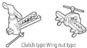
natural_image
Two types of clutch-type wing nut tools shown in line drawings (no text or symbols on the tools themselves)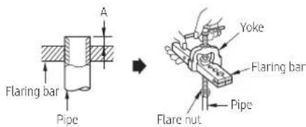
| Pipe diameter [D, mm (inch)] | Depth of flaring part [A, mm (inch)] | |||
| Using flaring tool for R-410A | Using conventional flaring tool | |||
| Clutch type | Wing nut type | |||
| ø6.35(ø1/4) | 0~0.5(0~0.02) | 1.0~1.5(0.04~0.06) | 1.5~2.0(0.06~0.08) | |
| ø9.52(ø3/8) | ||||
| ø12.70(ø1/2) | ||||
| ø15.88(ø5/8) | ||||
5 Check that you flared the pipe correctly.
– Refer to below illustrations for correct and incorrect examples of flared pipe.
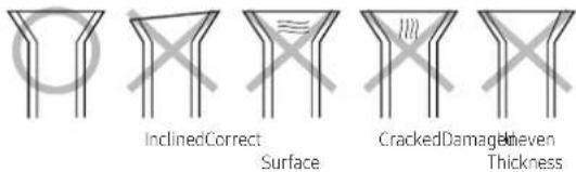

CAUTION
- If foreign matters or burrs are not removed after cutting pipe, refrigerant gas may leak.
- If foreign matters enter inside the pipe, important interior parts of the unit may get damaged or product efficiency will be reduced. So, the direction of pipe should be downward during pipe cutting or flaring.
English 23
Refrigerant pipe installation
Connecting the flared pipes
- Check if the flaring is properly done according to the standard size.
- Align the center of the piping and tighten the flare nut with your hands. Then, tighten the flare nut with torque wrench in a direction of the arrow indicated in below illustration.
- Make sure to use ester oil to coat the flare connection section.
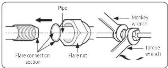
| Outer diameter (D) | Torque | Flare dimension (L) | Flare shape (mm) | |||
| mm inch N·m | lbf·ft mm inch | 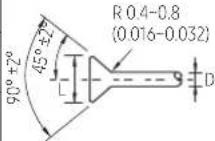 | ||||
| 6.35 1/4 | 14 ~ 18 | 10.3 ~ 13.3 | 8.7 ~ 9.1 | 0.34 ~ 0.36 | ||
| 9.52 3/8 | 34 ~ 42 | 25.1 ~ 31.0 | 12.8 ~ 13.2 | 0.50 ~ 0.52 | ||
| 12.7 1/2 | 49 ~ 61 | 36.1 ~ 45.0 | 16.2 ~ 16.6 | 0.64 ~ 0.65 | ||
| 15.88 5/8 | 68 ~ 82 | 50.2 ~ 60.5 | 19.3 ~ 19.7 | 0.76 ~ 0.78 | ||
CAUTION
- Blowing Nitrogen gas should be done when welding the pipe.
• Make sure to use the provided flare nut.
• Make sure that there are no cracks or twisted part when you need to bend the pipe. - Do not fasten the flare nut with excessive strength.
- R-410A is a high pressure refrigerant and there is a risk of refrigerant leakage if the flare connection is not coated with ester oil. Therefore, apply ester oil to coat the flare connection area.
Pipe installation for an outdoor unit
1 Direction of the pipe Refrigerant pipe can be withdrawn from the front, left and right side. Take necessary method to install the pipes according to the condition of the installation site.
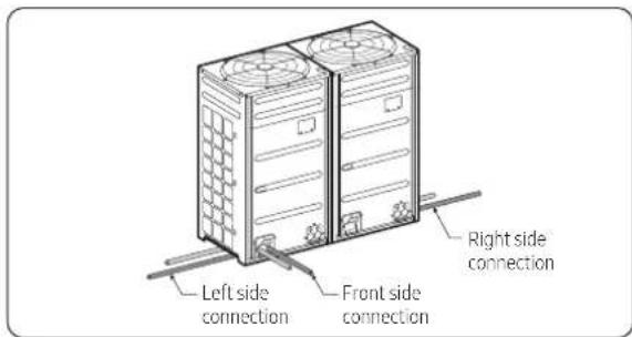
CAUTION
- Caution for using knock-out hole
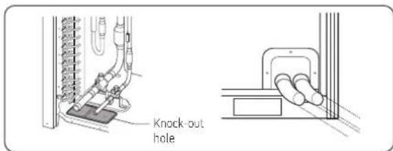
- Make sure to prevent any damages on the exterior of the outdoor unit.
- Remove all burrs around the knock-out hole and apply varnish on the cross section and edges of the knock-out hole to prevent rust.
- Use a cable protection tube and bushing to prevent a cable from being damaged when passing through a knock-out hole.
2 Connecting refrigerant pipe for outdoor unit
| Classification Front side connection Right/left (and bottom) side connection | ||
| Working process | First, remove the piping cover from the outdoor unit.Separate the knock-out hole that you are going to use. If you separate the knock-out hole that is going to be unused, small animals such as squirrels and rats may get into the unit through the hole.Fix the bottom side of the piping cover first and then fix the top part of it. | Separate the knock-out hole at the bottom side of the unit and install the pipe.After installing and insulating the pipe, close up the remaining holes. If not, small animals such as rats and squirrels may get inside the unit. |
| H/P | 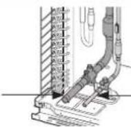 —— Liquid side pipe Gas side pipe —— Liquid side pipe Gas side pipe | 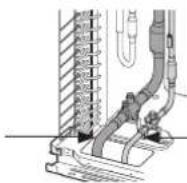 —— Liquid side pipe Gas —— Liquid side pipe Gas |
| H/R | 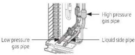 | 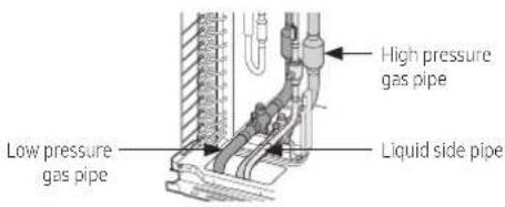 |

CAUTION
- Caution for welding the pipe to an outdoor unit
- When welding the pipe, the unit may get damaged by the heat and flame from welding. Use a flame proofing cloth to protect the unit from a welding fire or flame. Sensor for detecting outside temperature is located on the left side of the welding part so be extra careful not to damage the sensor when welding.
- The O-ring and Teflon packing inside service valve may get damaged by the heat from welding. Wrap the bottom side of the service valve with a wet cloth and weld it as shown in the illustration. Also, water dripping from the wet cloth may interrupt the welding. Make sure the water does not drip from the wet cloth.
- Make sure that connected pipes does not interrupt each other or make contact with the product. (Vibration may cause damage to the pipes.)
- When removing the sealed pipe on the bottom side of the service valve, cut it with a pipe cutter first and then start the welding. When the sealed pipe is welded without cutting, you may get injured by the refrigerant within the pipe.
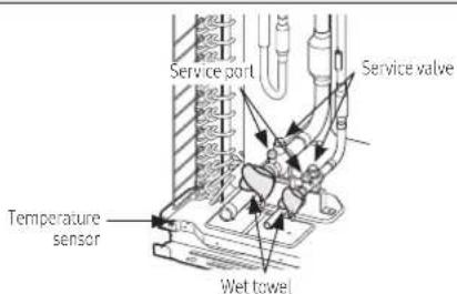
English 25
Refrigerant pipe installation
3 Pipe installation between the outdoor units
- You will need branch joints, which is an optional accessory, for connecting in between outdoor units in order to combine outdoor units in module.
For optimal distribution of the refrigerant, you must use Y-joint as branch joint for connecting outdoor units. (Do not use T-joint) - When you install the outdoor units in module, there is no restriction of installation order among outdoor units.
• Height of the connection pipe should be same or lower than the ones connected to the outdoor units. - Check the changes in comparison with the DVM II, III and IV.
| Caution Correct installation Incorrect installation | ||
| Refrigerant pipes should be connected at the same or lower level than the ones connected to the outdoor unit. | 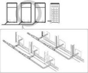 | 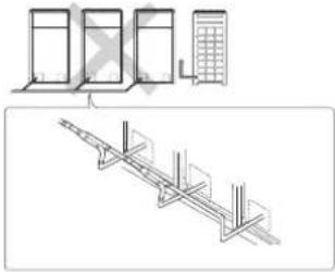 |
| Refrigerant pipes must be connected by the side of the product. | 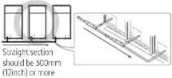 | 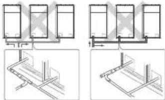 |
| Branch joint between outdoor units must be installed horizontally.. | 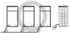 | 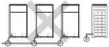 |
| Install a vertical trap in following cases as shown in the figure :Case1. Pipe length between outdoor unit branches exceeds 2.5m(8.20ft).Case2. Pipe length between outdoor unit and its branch exceeds 2.5m(8.20ft). | 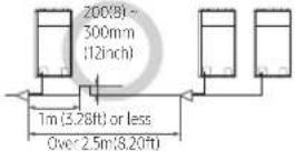 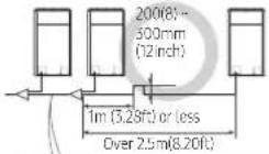 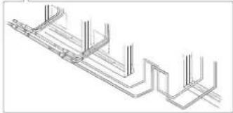 | 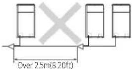 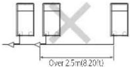 |
Examples of refrigerant pipe installation
1 Using Y-joint
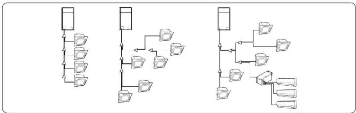
flowchart
graph TD
    A["Server 1"] --> B["Desktop"]
    A --> C["Desktop"]
    A --> D["Desktop"]
    A --> E["Desktop"]
    B --> F["Central Hub"]
    C --> F
    D --> F
    E --> F
    F --> G["Desktop"]
    G --> H["Desktop"]
    G --> I["Desktop"]
    G --> J["Desktop"]
    H --> K["Central Hub"]
    I --> K
    J --> K
    K --> L["Desktop"]
    L --> M["Desktop"]
    L --> N["Desktop"]
    L --> O["Desktop"]
    M --> P["Central Hub"]
    N --> P
    O --> P
    P --> Q["Desktop"]
    Q --> R["Desktop"]
    Q --> S["Desktop"]
    Q --> T["Desktop"]
2 Using distribution header
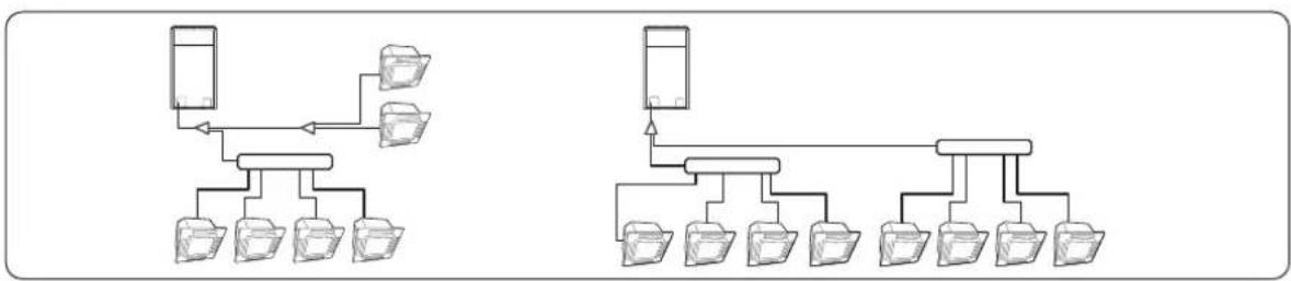
flowchart
graph TD
    A[" "] --> B[" "]
    B --> C[" "]
    B --> D[" "]
    B --> E[" "]
    C --> F[" "]
    D --> G[" "]
    E --> H[" "]
    F --> I[" "]
    G --> J[" "]
    H --> K[" "]
    I --> L[" "]
    J --> M[" "]
    K --> N[" "]
    L --> O[" "]
    M --> P[" "]
English 27
Refrigerant pipe installation
Allowable length of the refrigerant pipe and the installation examples
| Classification Single Installation Module installation | ||
| Installing only with Y-joint | Outdoor unit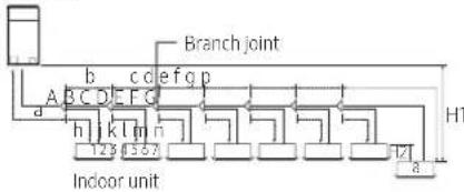 | Outdoor unit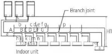 |
| Installing with Y-joint and distribution header | Outdoor unit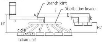 | Outdoor unit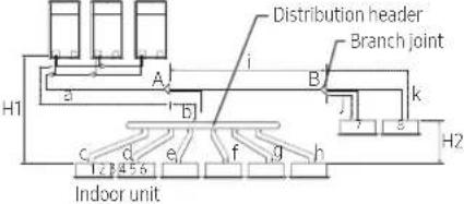 |
| Installing only with distribution header | Outdoor unit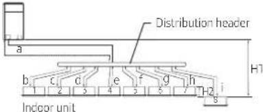 | Outdoor unit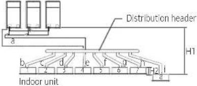 |
| Classification | Example | Remarks | ||||
| Maximum allowable length of pipe | Outdoor unit ~ Indoor unit | Actual length (Equivalent length) | 200 m(656') and below [220 m(722') and below] | Installing only with Y-joint | a+b+c+d+e+f+g+p ≤ 200 m(220 m)/656'(722') | Equivalent length Y-joint: 0.5 m (1.64'), Distribution header: 1 m(3.28') |
| Installing with Y-joint and distribution header | a+b+h ≤ 200m (220m), a+i+k ≤ 200 m(220 m)/656'(722') | |||||
| Installing only with distribution header | a+i ≤ 200 m(220 m)/656'(722') | |||||
| Total length of pipe (m) | 1000 m(3281') or less | Installing only with Y-joint | a+b+c+d+e+f+g+h+i+j+k+l+m+n+p ≤ 1000 m (3281') | - | ||
| Installing with Y-joint and distribution header | a+b+c+d+e+f+g+h+i+j+k ≤ 1000 m (3281') | - | ||||
| Installing only with distribution header | a+b+c+d+e+f+g+h+i ≤ 1000 m (3281') | - | ||||
| Outdoor unit ~ Outdoor unit (Module installation) | Pipe length | 10 m (33') or less | x ≤ 10 m (33'), y ≤ 10 m (33'), z ≤ 10 m (33') | 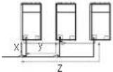 | ||
| Equivalent length | 13 m (43') or less | x ≤ 13 m (43'), y ≤ 13 m (43'), z ≤ 13 m (43') | ||||
| Maximum allowable height difference of pipe | Outdoor unit ~ Indoor unit | 110/110 m(361'/361) ^Note 21 | H1 ≤ 110/110 m(361'/361') | |||
| Indoor unit ~ Indoor unit | 50 m (164') or less | H2 ≤ 50 m (164') | ||||
| But, when wall-mount type indoor units with EEV (AM****NQD* / AM****NVD*) is installed, H2 is 15 m(49') or less.Classification Example Remarks | ||||||
| Maximum allowable length after branch joint | First branch joint ~ Farthest Indoor unit | Pipe length | 45 m (148') or less | Installing only with Y-joint | b+c+d+e+f+g+p ≤ 45 m (148') | - |
| Installing with Y-joint and distribution header | i+k ≤ 45 m (148') | |||||
| Installing only with distribu-tion header | i ≤ 45 m (148') | |||||
| 45 m~90 m (148'~295') Note 10 | Required conditions must be satisfied | - | ||||
| EEV kit Model name Remarks | |||||
| EEV kit ~ Indoor unit Actual pipe length | 2 m (6.6) | MEV-E24SA | 1 indoor | Apply to products without EEV (Wall mount & ceiling) | |
| MEV-E32SA | |||||
| 20 m (66') or less | MXD-E24K132A | 2 indoorMXD-E24K200A | |||
| MXD-E32K200A | |||||
| MXD-E24K232A | 3 indoor | ||||
| MXD-E24K300A | |||||
| MXD-E32K224A | |||||
| MXD-E32K300A | |||||
* Please refer to the EEV Kit manual.
Note 1) Required condition
| Classification Condition Example | ||
| First branch joint - Farthest Indoor unit | 45m(148') ≤ b+c+d+e+f+g+p ≤ 90m (295') : branch pipes ( b, c, d, e, f, g ) size must be increased by 1 grade | 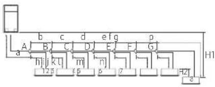 |
| Total length of extended pipe | If the size of pipe (main pipe), between the first branch joint and the outdoor unit, is not increased by 1 grade, a+(b+c+d+e+f+g)× 2+h+i+j+k+l+m+n+p ≤ 1000 m (3281') | |
| If the size of pipe (main pipe), between the first branch joint and the outdoor unit, is increased by 1 grade, (a+b+c+d+e+f+g)× 2+h+i+j+k+l+m+n+p ≤ 1000 m (3281') | ||
| Each Y-joint ~ Each indoor unit | h, i, j, ... p ≤ 45 m (148') | |
| Difference between the distance of the outdoor unit to the farthest indoor unit and nearest | ||
| indoor unit ≤ 45m(148'), (a+b+c+d+e+f+g+p)-(a+h) ≤ 45m (148') | ||
Note 2) When indoor unit is located at higher level than outdoor unit, allowable height difference is 110m(361'), (If the height difference is over 40m(131'), contact your local dealer for more information.)
but when the indoor unit is located at lower level than outdoor unit, allowable height difference is 110m(361') (If the height difference is over 50m(164'), need to decide whether to install PDM kit or not.)
Model name of the PDM kit: MXD-A38K2A, MXD-A12K2A, MXD-A58K2A
English 29
Refrigerant pipe installation
Installing the branch joints
Branch joints must be installed 'horizontally' or 'vertically'.
Horizontal installation
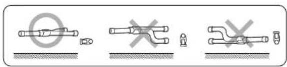
natural_image
Three schematic diagrams of pipe fittings with no text or symbols, showing different mechanical or electrical configurations (no readable text or labels)Vertical installation
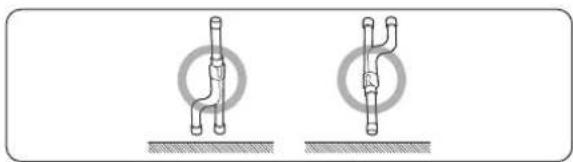
natural_image
Two identical pipe fittings with circular components, placed on a textured surface (no text or symbols)
NOTE
- For A\~J type branch joints: Connect the branch joint to the connection pipe with the provided reducer.
- For K\~Z type branch joints: Cut the connection part of the branch joint or the provided socket, according to the diameter of the connection pipe, before connecting them.
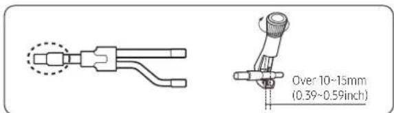

CAUTION
• Install the branch joint within ±15° of the horizon or vertical line.
• Make sure that the pipe is not bent at where it is connected to the branch joint.
- Keep a minimum straight line distance of 500mm (20inch) or more before connecting branch joint.
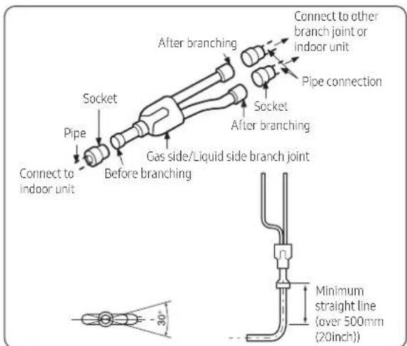
※ Install within ±15° of the horizon or vertical line.
Installing the distribution header
1 Select the reducer that fits the diameter of the pipe.
![Pipe* To outdoor unit Socket Provided item Socket Pipe* To indoor unit [Liquid side] Pipe* To outdoor unit Socket Socket To indoor unit [Gas side]](/content/2026/05/1065471/images/7ee4b2910123749de5aa5381cf5ca2d5e2d7aa768dc21331b3db8fa652e0c73f.jpg)
※ Pipe : Separately purchased item
2 If the number of connected indoor unit is fewer than ports on the distribution header, block the unused ports with caps.
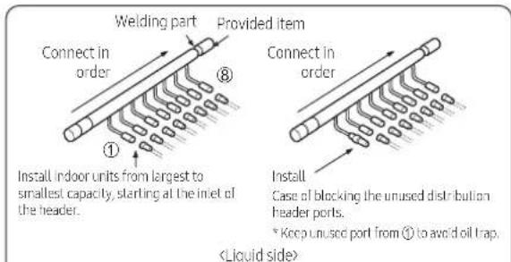
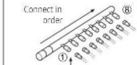
Install indoor units from largest to smallest capacity, starting at the inlet of the header.
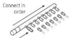
Install
Case of blocking the unused distribution header ports.
* Keep unused port from ① to avoid oil trap.

NOTE
- For A\~J type distribution header: Connect the distribution header to the connection pipe with the provided reducer.
- For K\~Z type distribution headers: Cut the provided socket, according to the diameter of the connection pipe, before connecting it.
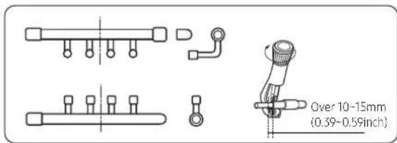

CAUTION
- Connect the indoor units in order, while respecting the direction of the arrow shown in the illustration.
- When indoor units are connected to same distribution head, indoor unit must be connected in order of their capacity, from largest to smallest.
- Keep unused port from ① to avoid oil trap.
3 Install the distribution header horizontally.
- Install the distribution header horizontally so that its ports does not face down.
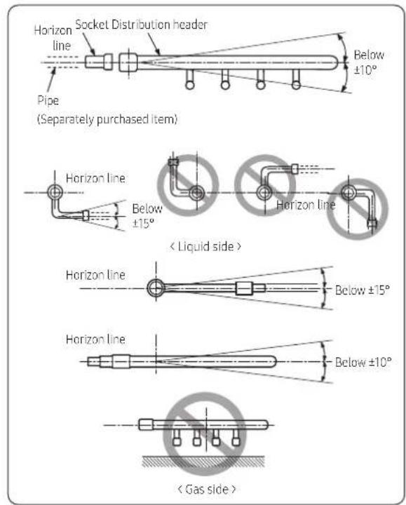
Installing the branch joint between outdoor units
Installation of outdoor joints
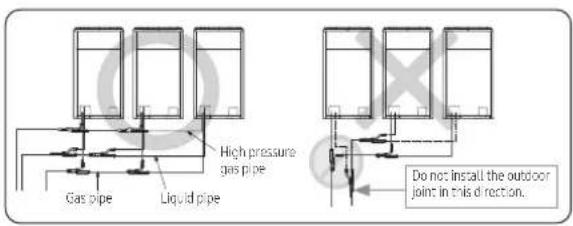
※ High pressure gas pipe only applies to the H/R product.
![To other outdoor unit To other outdoor joint or outdoor unit Pipe Pipe Pipe To other outdoor joint or Y-joint of the main pipe [Liquid side] Pipe Pipe Pipe To other outdoor unit To other outdoor joint or outdoor unit Reducer Reducer Reducer To other outdoor joint or Y-joint of the main pipe Pipe Pipe Pipe To other outdoor unit To other outdoor joint or outdoor unit Reducer Reducer Reducer To other outdoor joint or Y-joint of the main pipe](/content/2026/05/1065471/images/9f1d09b0941d1b3066781d5087e87dd8f62c909c6974bac19c9bbab7ed22f222.jpg)
※ Use the attached reducer according to the selected pipe size.

NOTE
- Connect the Outdoor joint to the pipe by cutting the outlet of the Outdoor joint or provided reducer properly.
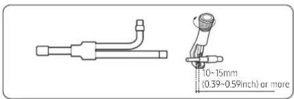
Electrical wiring work
Specification of the circuit breaker and power cable
| Model | MCA | MFA |
| AM080CXVAFH 28.0 | 40 AM160CXVAJH 28.0 | 35 |
| AM100CXVAFH 34.0 | 50 AM180CXVAJH 35.0 | 50 |
| AM120CXVAFH | 37.0 | 50 |
| AM140CXVAFH | 50.0 | 63 |
| AM160CXVAFH | 52.0 | 63 |
| AM180CXVAFH | 60.0 | 75 |
| AM200CXVAFH | 64.0 | 75 |
| AM220CXVAFH | 68.0 | 75 |
| AM240CXVAFH | 71.0 | 80 |
| AM260CXVAFH | 73.0 | 80 |
| AM080CXVAFC | 28.0 | 40 |
| AM100CXVAFC | 34.0 | 50 |
| AM120CXVAFC | 37.0 | 50 |
| AM140CXVAFC | 50.0 | 63 |
| AM160CXVAFC | 52.0 | 63 |
| AM180CXVAFC | 60.0 | 75 |
| AM200CXVAFC | 64.0 | 75 |
| AM220CXVAFC | 68.0 | 75 |
| AM240CXVAFC | 71.0 | 80 |
| AM260CXVAFC | 73.0 | 80 |
| AM080CXVAJH | 17.4 | 20 |
| AM100CXVAJH | 18.8 | 25 |
| AM120CXVAJH | 20.6 | 25 |
| AM140CXVAJH | 26.2 | 35 |
| Model | MCA | MFA |
| AM200CXVAJH | 38.0 | 50 |
| AM220CXVAJH | 41.0 | 50 |
| AM240CXVAJH | 45.0 | 50 |
| AM260CXVAJH | 49.0 | 63 |
| AM280CXVAJH | 50.0 | 63 |
| AM300CXVAJH | 55.0 | 63 |
| AM320CXVAJH | 58.0 | 75 |
| AM340CXVAJH | 61.0 | 75 |
| AM080CXVAJC | 17.4 | 20 |
| AM100CXVAJC | 18.8 | 25 |
| AM120CXVAJC | 20.6 | 25 |
| AM140CXVAJC | 26.2 | 35 |
| AM160CXVAJC | 28.0 | 35 |
| AM180CXVAJC | 35.0 | 50 |
| AM200CXVAJC | 38.0 | 50 |
| AM220CXVAJC | 41.0 | 50 |
| AM240CXVAJC | 45.0 | 50 |
| AM260CXVAJC | 49.0 | 63 |
| AM280CXVAJC | 50.0 | 63 |
| AM300CXVAJC | 55.0 | 63 |
| AM320CXVAJC | 58.0 | 75 |
| AM340CXVAJC | 61.0 | 75 |
- When installing outdoor units in module, select the power supply cable according to the sum of outdoor unit capacity. (Refer to the table for each model)
- Power Supply cords of parts of appliances for outdoor use shall not be lighter than polychloroprene sheathed flexible cord. (Code designation IEC:60245 IEC 66 / CENELEC: H07RN-F) Ex.) AM500*XV***
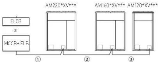
-①- AM500*XV***:35 mm ^2
-②- AM280*XV***:16 mm²
-③- AM120*XV***:4 mm²

CAUTION
- Caution for electrical work
- You must install ELCB or MCCB + ELB
- ELCB: Earth leakage breaker
- MCCB: Molded case circuit breaker
-
ELB: Earth leakage breaker
-
Do not operate the outdoor unit before completing the refrigerant pipe work.
- Do not disconnect or change the cable inside the product. It may cause damage to the product.
- Specification of the power cable is selected based on following installation condition; culvert installation/ ambient temperature 30^ (86°F)/ single multi conductor cables. If the condition is different from the ones stated, please consult an electrical installation expert and re-select the power cable.
- If the length of power cable exceed 50m (164.04ft), re-select the power cable considering the voltage drop.
- Use a power cable made out of incombustible material for the insulator (inner cover) and the sheath (outer cover).
- Do not use the power cable with the core wire exposed due to insulator damage occurred during removal of the sheath. When the core wire is exposed, it may cause fire.
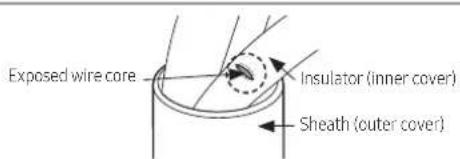
(The example of exposed core wire)
32 English
Power and communication cable configuration
- Main power and the ground cable must be withdrawn through the knock-out hole on the bottom-right or right side of the cabinet.
- Withdraw the communication cable from the designated knock-out hole on the bottom-right side of the front part.
• Install the power and communication cable using separate cable protection tube. - Fix a protection tube to the knock-out hole on the outdoor unit by using a CD connector or bushing. Make sure to use insulating bushing.
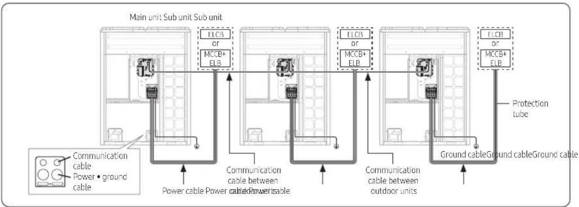
flowchart
graph TD
    A["Main unit Sub unit Sub unit"] --> B["Protection tube"]
    A --> C["Ground cable"]
    B --> D["Power cable"]
    B --> E["Ground cable"]
    C --> F["Power cable Power"]
    C --> G["Ground cable Power"]
    D --> H["Communication cable between outdoor units"]
    E --> I["Communication cable between outdoor units"]
    F --> J["Communication cable between outdoor units"]
    G --> K["Communication cable between outdoor units"]
Specification of the protection tube
| Name Temper grade Applicable conditions | ||
| Flexible PVC conduit | PVC | When the protection tube is installed indoor and not exposed to outside, because it is embedded in concrete structure |
| Class 1 flexible conduit | Galvanized steel sheet | When the protection tube is installed indoor but exposed to outside so there are risk of damage to the protection tube |
| Class 1 PVC coated flexible conduit | Galvanized steel sheet and Soft PVC compound | When the protection tube is installed outdoor and exposed to outside so there are risk of damage to the protection tube and extra waterproof is needed |

CAUTION
- Caution for perforating the knock-out hole
• Perforate a knock-out hole by punching it with a hammer.
• After perforating the knock-out hole, apply rust resisting paint around the hole.
- When you need to pass the cables through the knock-out hole, remove burrs on the hole and protection the cable with a protection tape or bushing etc.
- Caution for installing communication cable
- When you connect the cable, it may sag and pressed by other parts. Therefore cables should be fixed to a clamp highlighted with a box on the illustration.
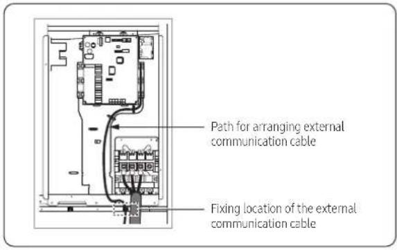
English 33
Electrical wiring work
Power wiring diagram
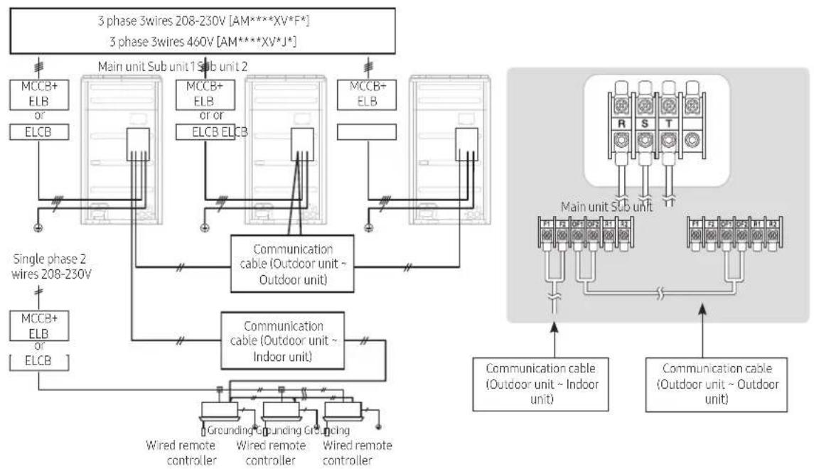
flowchart
graph TD
    A["3 phase 3wires 208-230V [AM****XV*F*"]]
    B["3 phase 3wires 460V [AM****XV*J*"]]
    C["MCCB+ ELB or ELCB"] --> D["Main unit Sub unit 1 Sub unit 2"]
    D --> E["MCCB+ ELB or ELCB"]
    E --> F["Communication cable (Outdoor unit ~ Outdoor unit)"]
    G["MCCB+ ELB or ELCB"] --> H["Single phase 2 wires 208-230V"]
    H --> I["MCCB+ ELB or ELCB"]
    I --> J["Grounding"]
    J --> K["Wired remote controller"]
    J --> L["Wired remote controller"]
    J --> M["Wired remote controller"]
    N["Communication cable (Outdoor unit ~ Indoor unit)"] --> O["Main unit Sub unit"]
    O --> P["Main unit Sub unit"]
    P --> Q["Communication cable (Outdoor unit ~ Indoor unit)"]
    Q --> R["Communication cable (Outdoor unit ~ Outdoor unit)"]
- Connect a power cable of the outdoor unit after checking that R-S-T (3 phase 3 wire) is properly connected.
- Malfunction may occur if one or more of the wires among R-S-T phases (3 Phases-3 Wires) are not connected properly. (*Malfunction: Turning on/off, occurrence of error, consecutive reset)
• Communication cable between indoor and outdoor units and communication cable between outdoor units has no polarity.
- Arrange the cables with a cable tie.
※ ELCB and ELB must be installed since there is risk of electric shock or fire when they are not installed.
Selecting solderless ring terminal
- Select a solderless ring terminal for a power cable according to the nominal dimensions for cable.
- Apply insulation coating to the connection part of the solderless ring terminal and the power cable.
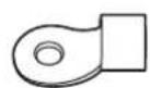
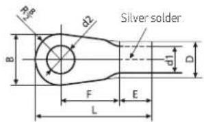
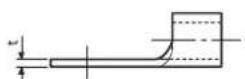
| Nominal dimensions for cable[mm2 (inch2)] | 4/6 (0.006/0.009) 10 | (0.01) 16 (0) | 02) 25 (0.03) | 35 (0.05) 50 (0.07) 70 (0.10) | |||||||
| Nominal dimensions for screw[mm (inch)] | 4 (3/8) 8 | 3/16) 8 (3/16) | 6) 8 (3/16) 8 | (3/16) 8 (3/16) | 6) 8 (3/16) 8 | (3/16) 8 (3/16) | 16) 8 (3/16) | ||||
| B | Standard dimension[mm (inch)] | 9.5 (3/8) 15 | (9/16) 15 | (9/16) 16 (10) | (6) 12 (1/2) | 16.5(10/16) | 16 (10/16) | 2 (7/8) 22 (7/8) 24 (1) | |||
| Allowance[mm (inch)] | ±0.2 (±0.007) | ±0.2(±0.007) | ±0.2(±0.007) | ±0.3 (±0.011) ±0.3 | (±0.011) | ±0.3(±0.011) | ±0.4(±0.015) | ||||
| D | Standard dimension[mm (inch)] | 5.6 (1/4) | 7.1 (1/4) | 9 (3/8) | 11.5 (7/16) | 13.3 (1/2) | 13.5 (1/2) | 17.5 (1/2) | |||
| Allowance[mm (inch)] | +0.3 (+0.011)-0.2 (-0.007) | +0.3(+0.011)-0.2(-0.007) | +0.3(+0.011)-0.2(-0.007) | +0.5 (+0.019)-0.2 (-0.007) | +0.5 (+0.019)-0.2 (-0.007) | +0.5(+0.019)-0.2(-0.007) | +0.5(+0.019)-0.4(-0.015) | ||||
| d1 | Standard dimension[mm (inch)] | 3.4 (1/8) | 4.5 (3/16) | 5.8 (1/4) | 7.7 (5/16) | 9.4 (3/8) | 11.4 (7/16) | 13.3 (1/2) | |||
| Allowance[mm (inch)] | ±0.2 (±0.007) | ±0.2(±0.007) | ±0.2(±0.007) | ±0.2 (±0.007) | ±0.2 (±0.007) | ±0.3(±0.011) | ±0.4(±0.015) | ||||
| E | Min. [mm (inch)] | 6 (1/4) | 7.9 (5/16) | 9.5 (5/16) | 11 (3/8) | 12.5 (1/2) | 17.5 (11/16) | 18.5 (3/4) | |||
| F | Min. [mm (inch)] | 5 (3/16) | 9 (3/8) | 9 (3/8) | 13 (1/2) | 15 (5/8) | 13 (1/2) | 13 (1/2) | 13 (1/2) | 14 (9/16) | 20 (3/4) |
| L | Max. [mm (inch)] | 20 (3/4) | 28.5 (1-1/8) | 30 (1-3/16) | 33 (1-5/16) | 34 (1-3/8) | 38 (1-1/2) | 43 (1-11/16) | 50 (2) | 51 (2) | |
| d2 | Standard dimension[mm (inch)] | 4.3 (3/16) | 8.4 (1-3/16) | 8.4 (1-3/16) | 8.4 (1-3/16) | 8.4 (1-3/16) | 8.4 (1-3/16) | 8.4 (1-3/16) | 8.4 (1-3/16) | 8.4 (1-3/16) | 8.4 (1-3/15) |
| Allowance [mm (inch)] | +0.2(+0.007)0 (0) | +0.4(+0.015)0 (0) | +0.4(+0.015)0 (0) | +0.4(+0.015)0 (0) | +0.4 (+0.015)0 (0) | +0.4 (+0.015)0 (0) | +0.4(+0.015)0 (0) | +0.4(+0.015)0 (0) | |||
| t | Min. [mm (inch)] | 0.9 (0.03) | 1.15 (0.04) | 1.45 (0.05) | 1.7 (0.06) | 1.8 (0.07) | 1.8 (0.07) | 2.0 (0.078) | |||
Connecting the power terminal
- Connect the cables to the terminal board with solderless ring terminals.
- Properly connect the cables by using certified and rated cables and make sure to fix them properly so that external force is not applied to the terminal.
- Use a driver and wrench that can apply the rated torque when tightening the screws on the terminal board.
- Tighten the terminal screws by complying rated torque value. If the terminal is loose, fire can occur due to arc heat generation and if the terminal is too tight, terminal board could get damaged.
1 Front connection
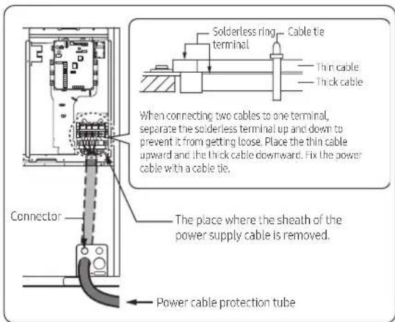
English 35
Electrical wiring work
2 Closing the cover
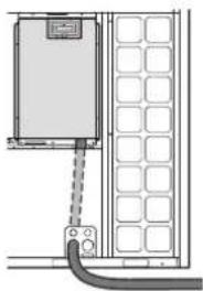
natural_image
Diagram of an electrical enclosure with a cable and grid-patterned panel (no text or symbols)| Screw | Tightening torque for terminal | Remarks | |
| N·m lbf·ft | |||
| M3.5 0.7 | 8~1.18 0.6 | 0.9 communication cable | |
| M4 1.2 | 1.8 0.9~1.3 | Single phase | 208~230V power cable |
| M8 | 5.5~7.3 | 4.1~5.4 | 3 phase 208~230V / 460V power cable |

CAUTION
- When removing the outer sheath of the power supply cable, be careful not to scratch the inner sheath of the cable.
- Make sure that more than 20mm (0.79 inch) of the outer sheath of the indoor unit power and communication cable are inside the electrical component box.
• Install the communication cable separately from power cable and other communication cables. - There is a risk of electric shock when power is applied. Close the cover of the control box before proceeding to work.
- To inspect the compressor or PBA, first make sure to turn off the system. Electricity may flow even in a compressor that has not been used recently. Exercise caution to protect yourself from an electric shock.
Examples of how to use the cable striper
1 Adjust the blade position by coin. (Controller is at the bottom side of the tool.) Fix the blade position according to the outer sheath thickness of the power cable.
2 Fix the power cable and tool by using the hook at the top side of the tool.
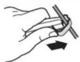
3 Cut out the outer sheath of the power cable by revolving the tool in the direction of the arrow, two or three times.
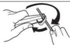
4 At this situation, cut out the outer sheath of the power cable by moving the tool toward the direction of the arrow.
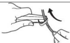
5 Slightly bend the wire and pull out the cut part of the outer sheath.
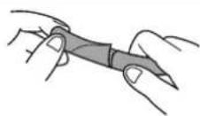
Fixing the power cable
3 phase 3wires 208-230V
[AM***XV*F*]
3 phase 3wires 460V
[AM****XV*J*]
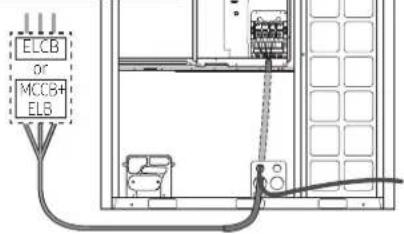
Sub unit communication cable

CAUTION
- Do not let the power cable come into contact with the pipes inside the outdoor unit. If the power supply cable touches the pipes, the vibration of the compressor is transferred to the pipes and can damage the power supply cables or pipes, creating the danger of fire or explosion.
- Make sure that the place where the sheath of power supply cable is removed is inside the power supply box. If it is impossible, you should connect the protection tube for power cable to the power supply box.
• After arranging the power cable into the power supply box, tighten the cover.
Connect the ring terminal of 3 phase cable
1 Cut the power cable to an appropriate length and connect it with the solderless terminal.
2 After connecting the power cable to the terminal as seen in the illustration, fix it with cable tie.
3 Fix the housing, which has an insulator, to the terminal board.
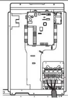
Fixing the ground cable
- Connect the ground cable to the grounding hole inside the power supply box.
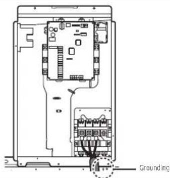
Withdrawing the power cable
- Withdrawing from the front side
- Connect the power cable protection tube into the power supply box as shown picture.
- Be sure that the power supply cable is not damaged by burn on the knock-out hole.
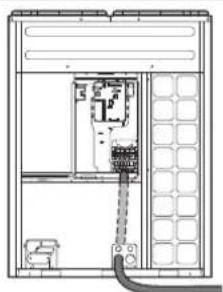
natural_image
Technical line drawing of an electrical enclosure with internal components and wiring (no text or symbols)Installing the Solution device
- When the number of indoor units installed with the outdoor unit is 16 or less
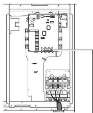
| F1 F2 OF1 OF2 R1 | R2 | |||
| Terminal block with indoor unit | Terminal block with outdoor unit sub module | Terminal block with solution device | ||
Where to install the interface module
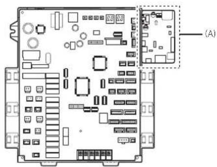
- Install the interface module in location (A), considering the installation conditions. - For details on how to install, refer to the interface module installation manual.
English 37
Electrical wiring work
Grounding work
Grounding must be done by a qualified installer for your safety.
Grounding the power cable
• The standard of grounding may vary according to the rated voltage and installation place of the air conditioner.
- Ground the power cable according to the following table.
| Installation place\Power condition | Voltage to ground is lower than 150V Voltage | to ground is over 150V |
| High humidity | Must perform the grounding work 3.^Note1) (Including the case where earth leakage breaker is installed) | |
| Average humidity Perform grounding work 3.^Note1) | Must perform the grounding work 3.^Note1) (Including the case where earth leakage breaker is installed) | |
| Low humidity | Perform grounding work 3 , if possible, for your safety. ^Note2) | |
Note 1) About grounding work 3.
- Grounding work must be done by an expert (with qualification).
- Check if the grounding resistance is lower than 100Ω. When installing an earth leakage breaker (that can cut the electric circuit within 0.5 second in case of a short circuit), allowable grounding resistance should be 30\~500Ω.
Note 2) Grounding at dry place
- The grounding resistance should be lower than 100 . Even in worst case, grounding resistance should be lower than 250 .
Performing the grounding work
• Use a rated grounding cable by referring to the specification of the electric cable for the outdoor unit.
* When using the exclusive grounding terminal (When the grounding terminal is already built on the house)
※ When using grounding of the switch board
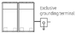
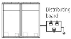
Air tightness test and vacuum drying
Air tightness test
- Use tools for R-410A to prevent the inflow of foreign substances and resist against the internal pressure.
- Do not remove the core of filling port.
- Use dry nitrogen gas for air tightness test as shown in the illustration.
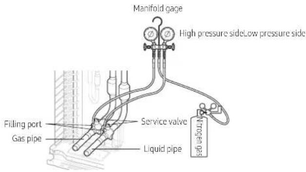
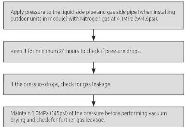
flowchart
graph TD
    A["Apply pressure to the liquid side pipe and gas side pipe (when installing outdoor units in module) with Nitrogen gas at 4.1MPa (594.6psi)."] --> B["Keep it for minimum 24 hours to check if pressure drops."]
    B --> C["If the pressure drops, check for gas leakage."]
    C --> D["Maintain 1.0MPa (145psi) of the pressure before performing vacuum drying and check for further gas leakage."]
If you apply pressure at more than 4.1MPa (594.6psi), pipes may get damaged. Apply pressure with pressure regulator and pay attention to the pressure of the nitrogen.
After applying Nitrogen gas, check there's any change of pressure, using a pressure regulator.
If the pressure is changed, apply soap water to check for leakage and check the pressure of the nitrogen gas again.
After checking the first gas leakage, maintain 1.0MPa (145psi) to check for further gas leakage.

CAUTION
- Perform a Nitrogen gas leak test with the service valve of the outdoor unit closed.
- When charging the nitrogen gas, charge it from the both (high-low pressure) sides.
- If the pipe is filled in a short time with a highly excessive pressure of Nitrogen gas, the pipes may get damaged. Make sure to use a regulator to prevent the high pressure Nitrogen gas, over 4.1MPa (594.6psi), from entering into the pipe.
English 39
Air tightness test and vacuum drying
Vacuum drying pipes and indoor units
- Use tools for R-410A to prevent the inflow of foreign substances and resist against the internal pressure.
- Use vacuum pump that allows vacuuming under -100.7kPa (5 Torr).
- Use the vacuum pump with the check valve to prevent pump oil from flowing backward while the vacuum pump is stopped.
- Completely close the liquid gas side service valve of the outdoor unit.
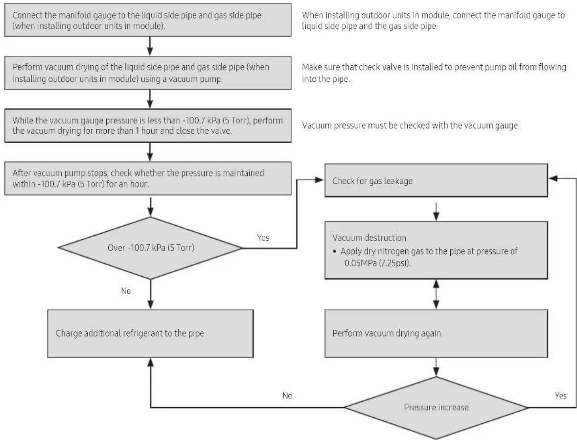
flowchart
graph TD
    A["Connect the manifold gauge to the liquid side pipe and gas side pipe (when installing outdoor units in module)."] --> B["Perform vacuum drying of the liquid side pipe and gas side pipe (when installing outdoor units in module) using a vacuum pump."]
    B --> C["While the vacuum gauge pressure is less than -100.7 kPa (5 Torr), perform the vacuum drying for more than 1 hour and close the valve."]
    C --> D["After vacuum pump stops, check whether the pressure is maintained within -100.7 kPa (5 Torr) for an hour."]
    D --> E{Over -100.7 kPa (5 Torr)}
    E -->|Yes| F["Check for gas leakage"]
    E -->|No| G["Charge additional refrigerant to the pipe"]
    F --> H["Vacuum destruction<br>• Apply dry nitrogen gas to the pipe at pressure of 0.05MPa (7.25psi)."]
    H --> I["Perform vacuum drying again"]
    I --> J{Pressure increase}
    J -->|Yes| K["End"]
    J -->|No| D
    style A fill:#ccc,stroke:#333
    style K fill:#ccc,stroke:#333
※ If the pressure rises in an hour, either water is remaining inside the pipe or there is a leakage.
When the ambient temperature of vacuuming pipe is low (less than 0^ C ( 32^ F)), moisture might remain within the pipe. Therefore, pay special attention to the pipe sealing in the winter.
Pipe insulation
Insulating the refrigerant pipes and branch joints
- Check for gas leakage before completing (the hose and pipe insulation) and if there is no sign of leakage, make sure to insulate the pipes and hoses.
- Use EPDM material insulator that meets the following conditions.
| Test item Unit Standard | ||
| Density g/cm | ^3 | 0.048~0.096 |
| Dimensional change rate by heat | % Below -5 | |
| Absorption rate g/cm | ^3 | Below 0.005 |
| Thermal conduction rate W/m·K Below 0.037 | ||
| Moisture transpiration factor | ng/(m2·s·Pa) Below 15 | |
| Moisture transpiration grade | g/(m2·24h) Below 15 | |
| Formaldehyde dispersion mg/L | There should be none | |
| Oxygen rate % Over | 25 | |
Selecting the refrigerant pipe insulator
• Insulate the gas pipe and liquid pipe by referring to the thickness of insulator for each pipe size.
- The standard condition is; temperature at 30°C (89.6°F), humidity less than 85%. If case if the humidity is higher, you must increase the size by one grade as stated in below table.
| Pipe | Diameter of refrigerant pipe | Insulator (Cooling-Heating) | Remarks | ||||
| General 1)[30 °C, 85 %] | High humidity 2)[30 °C, over 85 %] | ||||||
| EPDM, NBR | |||||||
| mm inch mm inch mm | inch | ||||||
| Liquid | 6.35~9.52 | 1/4~3/8 | 9 | 3/8 | 9 | 3/8 | Heat resisting temperature over 120°C |
| 12.7~50.8 | 1/2~2 | 13 | 1/2 | 13 | 1/2 | ||
| Gas | 6.35 | 1/4 | 13 | 1/2 | 19 | 3/4 | |
| 9.52~25.4 | 3/8~1 | 19 | 3/4 | 25 | 1 | ||
| 28.58~44.45 | 11/8~13/4 | 19 | 3/4 | 32 | 11/4 | ||
| 50.8 | 2 | 25 | 1 | 38 | 11/2 | ||
^11 To install in any of the following places or environments, use the same insulating material used in general conditions.
- An air-conditioned place where humidity is high inside the ceiling tiles
- A space where temperature/humidity difference is large between the upper and lower air due to a high ceiling (e.g., a large chapel/church, cinema, split-level open lobby, lecture hall with theatre seating)
- A corridor or passageway with no air conditioning system
- An old building with poor insulation
[Under the following conditions, a gas pipe of ∅9.52 to ∅25.40 mm(3/8inch to 1inch) and plumbing of thickness 13mm(1/2) can be used]
- A general town centre building (e.g., an apartment building, dwelling house, lecture hall, educational institute building, office, shopping complex)
- A structure with an exposed ceiling
- A structure with ceiling tiles and a ventilation system
- A structure where there is no inflow of air from the outside due to plumbing laid inside a wall
※ Even in the above conditions, if humidity is very high or condensation is expected to occur, change the installation thickness for high humidity.
^2) To install in any of the following places or environments, use the same insulating material used in a place with high humidity.
- A location with high humidity, such as a seaside area, a hot spring area, an area near a pond/river or a ridge (a building that is partially covered in earth and sand)
- A location where morning dew occurs frequently (e.g., once every three days)
- Sauna, swimming pool or restaurant
- Installation inside a ceiling that is not air-conditioned where there is inflow of a large amount of moisture (plumbing installed along a corridor or near the entrance of a hall of residence or studio flat)
- A place where humidity is high due to an insufficient ventilation system in the space where plumbing is installed
- A room on a semi-basement floor
- If you are not sure which insulating material to use, choose material used in a place with high humidity.
- If the purpose of the room is subject to change, reconsider the thickness of insulating material.
- Use the specified insulating material only.
Insulate the refrigerant pipe
• Make sure to insulate the refrigerant pipe, branch joint, distribution header, and the connection part of the pipes.
• If you insulate the pipes, condensed water will not fall from the pipes.
- Check if there are any cracks on the insulation at the bent part of the pipe.
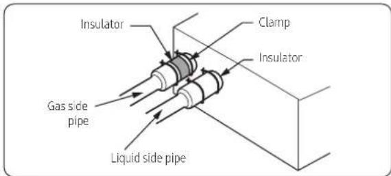
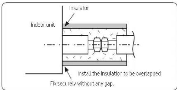
English 41
Pipe insulation
Insulating pipes
- The insulation of the gas and liquid pipes can be in contact with each other but they should not press excessively against each other.
- When the gas side and liquid side pipes are contacting each other, increase the thickness of the insulation by one grade.
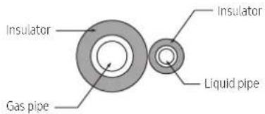
Insulating pipes connected behind the EEV kit
- When installing the gas side and liquid side pipes, leave at least 10mm of space.
- When the gas side and liquid side pipes are contacting each other, increase the thickness of the insulation by one grade.
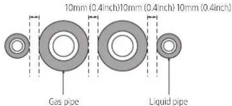

CAUTION
- Install the insulation without any gaps or cracks and use adhesive on the connection part of it to prevent moisture from entering.
- Bind the refrigerant pipe with insulation tape if it is exposed to outside sunlight. (When binding the pipe with finishing tape, be careful not to reduce the thickness of the insulation.)
• Install the refrigerant pipe respecting that the insulation does not get thinner on the bent part or hanger of pipe. - When the thickness of insulation is reduced, reinforce the reduced thickness with additional insulation.
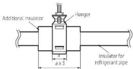
Insulate the distribution header
- Fix the distribution header with a cable tie and cover the connected part.
- Insulate the distribution header and the welded part and wrap the connected part with an adhesive insulation tape to prevent dew formation.
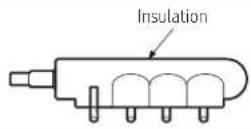
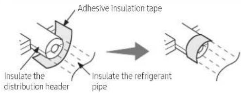
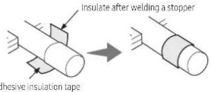
- Fix the distribution header with a hanger after insulating it.
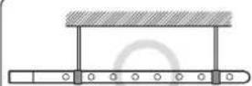
Insulating the branch joint
- Tightly attach the insulator, provided with the branch joint, to the separately purchased insulator. Wrap the connected part with an insulator (separately purchased item) that has thickness of at least 10mm (0.4inch).
- Use an insulator that resist heat up to 120°C (248°F). Wrap the branch joint with an insulation that has thickness of at least 10mm (0.4inch).
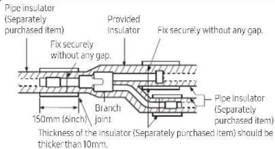
Insulation tape (Separately purchased item)
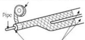
Pipe insulator (Separately purchased item)
※ Attach the adhesive insulation tape to the pipe, as shown in the picture, after insulating the pipe.
Insulating the pipe located inside of the outdoor unit
- With a pipe insulator, insulate the pipe up to whole service valve located inside of the outdoor unit.
- Seal the gap between the outdoor unit pipe and the insulator. Rainwater and dewdrops may soak through the gap between the pipe and the insulation of the outdoor unit installed on the outside.
- Separate the cover of the pipe and close it after insulation work. Only remove a knock-out hole cover where the pipe will be installed. If the knock-out hole is open unnecessarily, it must be closed. If not, small animals such as squirrels and rats may get into the unit through the hole and the unit may be damaged.
H/P
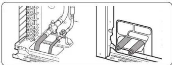
natural_image
Technical line drawings of mechanical components, one showing internal tubing and the other a side view with a rectangular component (no text or symbols)
CAUTION
- The filled-out label must be adhered in the proximity of the product charging port. (ex. onto the inside of the stop valve cover.)
Single installation
- Open the manifold gauge valve connected to the liquid side service valve and add the liquid refrigerant.
- If you cannot add the whole quantity of the refrigerant while the outdoor unit is stopped, open the gas side and liquid side service valve. Then, add remaining refrigerant by pressing the refrigerant adding button of the outdoor PCB.
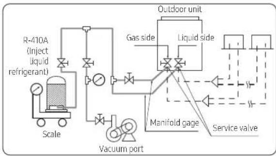
flowchart
graph TD
    A["R-410A (Inject liquid refrigerant)"] --> B["Scale"]
    B --> C["Vacuum port"]
    C --> D["Manifold gage"]
    D --> E["Outdoor unit"]
    E --> F["Liquid side"]
    F --> G["Gas side"]
    G --> H["Service valve"]
    H --> I["Ground"]
    style A fill:#f9f,stroke:#333
    style B fill:#ccf,stroke:#333
    style C fill:#cfc,stroke:#333
    style D fill:#fcc,stroke:#333
    style E fill:#cff,stroke:#333
    style F fill:#ffc,stroke:#333
    style G fill:#cfc,stroke:#333
    style H fill:#fcc,stroke:#333
    style I fill:#ffc,stroke:#333
Module installation
- Open the manifold gauge valve connected to the liquid side service valve and add the liquid refrigerant.
- If you cannot add the whole quantity of the refrigerant while the outdoor unit is stopped, open the gas side and liquid side service valve. Then, add remaining refrigerant by pressing the refrigerant adding button of the outdoor PCB.
- If you use the refrigerant charging function from the PCB, outdoor unit will operate and charge the refrigerant. At this time, you must use gas side manifold gauge for cooling operation and use charging port for heating at the manifold gauge for heating operation.
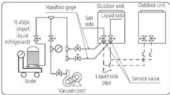
flowchart
graph TD
    A["Scale"] --> B["R-410A (Inject liquid refrigerant)"]
    B --> C["Manifold gage"]
    C --> D["Gas side"]
    D --> E["Liquid side pipe"]
    E --> F["Service valve"]
    F --> G["Outdoor unit"]
    G --> H["Outdoor unit"]
    H --> I["Liquid side"]
    I --> J["Liquid side"]
    J --> K["Vacuum port"]
English 43
Pipe insulation

CAUTION
- Open the gas side and liquid side service valve completely after charging the refrigerant. (If you operate the air conditioner with the service valve closed, the important parts may be damaged.)
- Put on safety equipment when charging refrigerant.
- Do not charge the refrigerant when you adjust or control other product such as indoor units or EEV kits.
- If you charge the refrigerant with the front cabinet open, be very careful with the fan on the top of the product to prevent personal injury.
- When the ambient temperature is low in winter time, do not heat the refrigerant container to speed up the charging process. There is risk of explosion.
- Beware for possibility of refrigerant leakage when you connect the manifold gauge to the charging port for heating.
- Close the valve of the refrigerant container immediately after charging the refrigerant. If not, there might be a change in entire amount of refrigerant.
Using service valve for gas
• After charging the refrigerant, close all caps as shown in the illustration.
- Tightening torque for the cap of refrigerant charging port 10\~12N·m (7.4 \~ 8.9 lbf·ft)
- Tightening torque for the cap of control part 20\~25N·m (14.8 \~ 18.4lbf·ft)
- Opening/closing torque for the valve
- ∅19.05mm (∅3/4inch) : 10 N·m (7.4 lbf·ft)
Cap for the control part
Cap for the refrigerant charging port
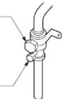
Basic segment display
| Step Display content Display | |||||
| At initial power input Checking segment display | SEG 1 SEG 2 | SEG 3 SEG 4 | |||
| "8" "8" "8" "8" | |||||
| While setting communication between indoor and outdoor unit (Addressing) | Number of connected indoor units | SEG 1 SEG 2 | SEG 3 SEG 4 | ||
| "A" "d" | Number of communicated unitsRefer to "View Mode" for communication address | ||||
| After communication setting (usual occasion) | MCU, Indoor unit address | SEG 1 SEG 2 | SEG 3 SEG 4 | ||
| I/U: "A"MCU: "C" | I/U: "0"MCU: "1" | Reception address (in decimal number) | |||
※ I/U : Indoor unit
Setting outdoor unit option switch and key function
Setting outdoor unit option switches
- Setting outdoor install option
| Step Button Display Description | Note | |||
| Outdoor unit address | ||||
| Step1 Outdoor unit display | od nd | Setting required - | ||
| Step2 | Press (K1+K2) for 2 seconds | od 00 | Unit address for module combination | 00: Main unit |
| K4 x 1 time | od 01 | 01: Sub1 unit | ||
| K4 x 2 times | od 02 | 02: Sub2 unit | ||
| K4 x 3 times | od 03 | 03: Sub3 unit | ||
| Step3 | If it is main unit, go to step4. Otherwise, press K2 button for 2 seconds to save & exit (system will be reset) | |||
| Quantity of indoor units | ||||
| Step4 Press K1 | Td 00 | Ready to set - | ||
| Step5 | K2 x n times | Td x 0 | Tens digit (0 ~ 6) | Ex) 03: 3 units64: 64 units |
| K4 x n times | Td 0x | Ones digit (0 ~ 9) | ||
| * K4: Press for 2 seconds - automatic detection of indoor units' quantity | ||||
| Step6 | If it is heat recovery model, go to step 7. Otherwise, press K2 button for 2 seconds to save & exit (system will be reset) | |||
| Quantity of MCUs * Heat recovery model only | ||||
| Step7 Press K1 | NC 00 | Ready to set - | ||
| Step8 | K2 x n times | NC x 0 | Tens digit (0 ~ 1) | Ex) 03: 3 units16: 16 units |
| K4 x n times | NC 0x | Ones digit (0 ~ 9) | ||
| * K4: Press for 2 seconds - automatic detection of MCUs' quantity | ||||
| Step9 K2: long | Ad 00 | Save Restart | ||
| * Press K1 for 2 seconds to exit without save regardless of setting step. | ||||
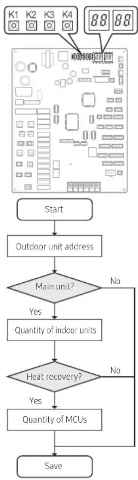
flowchart
graph TD
    A["Start"] --> B["Outdoor unit address"]
    B --> C{Main unit?}
    C -->|Yes| D["Quantity of indoor units"]
    C -->|No| E["Heat recovery?"]
    D --> F{Quantity of MCUs}
    F --> G["Save"]
    E --> G
English 45
Setting outdoor unit option switch and key function
Installing and setting the option with tact switch and explanation of the functions
Setting the option
1 Press and hold K2 to enter the option setting. (Only available when the operation is stopped)
- If you enter the option setting, display will show the following. (If you have set the 'Emergency operation for compressor malfunction', 1 or 2 will be displayed on Seg 4.)
- Seg 1 and Seg 2 will display the number for selected option.
- Seg 3 and Seg 4 will display the number for set value of the selected option.
2 If you have entered option setting, you can shortly press the K1 switch to adjust the value of the Seg1, Seg 2 and select the desired option.
Example)
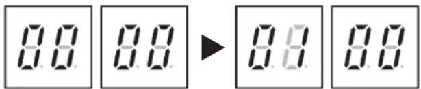
3 If you have selected desired option, you can shortly press the K2 switch to adjust the value of the Seg 3, Seg 4 and change the function for the selected option.
Example)
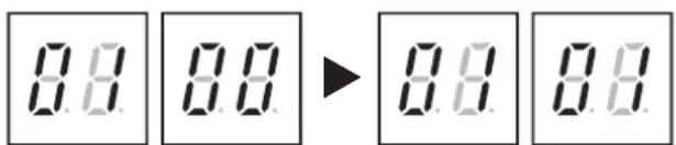
4 After selecting the function for options, press and hold the K2 switch for 2 seconds. Edited value of the option will be saved when entire segments blinks and tracking mode begins.
CAUTION
- Edited option will not be saved if you do not end the option setting as explained in above instruction.
※ While you are setting the option, you may press and hold the K1 button to reset the value to previous setting.
※ If you want to restore the setting to factory default, press and hold the K4 button while you are in the option setting mode.
- If you press and hold the K4 button, setting will be restored to factory default but it doesn't mean that restored setting is saved. Press and hold the K2 button. When the segments shows that tracking mode is in progress, setting will be saved.
| Optional item | Input unit | SEG1 | SEG2 | SEG3 | SEG4 | Function of the option | Remarks |
| Emergency operation for compressor malfunction | Individual 0 0 | 0 0 | Disabled (Factory default) | E560 will occur when all the compressors are set as malfunction state. | |||
| 0 | 1 | Set compressor 1 as malfunction state | |||||
| 0 | 2 | Set compressor 2 as malfunction state | |||||
| Capacity correction for cooling | Main 0 1 | 0 0 7 | 9 | Targeted evaporation temperature [°C].(When low temperature value is set, discharged air temperature of the indoor unit will decrease) | |||
| 0 1 5 | 7 (Factory default) | ||||||
| 0 2 | 9-11 | ||||||
| 0 3 | 10-12 | ||||||
| 0 4 | 11-13 | ||||||
| 0 5 | 12-14 | ||||||
| 0 6 | 13-15 | ||||||
| Capacity correction for heating | Main 0 2 | 0 0 | 3.0 (Factory default) | Targeted high pressure [MPa].(When low pressure value is set, discharged air temperature of the indoor unit will decrease) | |||
| 0 1 | 2.5 | ||||||
| 0 2 | 2.6 | ||||||
| 0 3 | 2.7 | ||||||
| 0 4 | 2.8 | ||||||
| 0 5 | 2.9 | ||||||
| 0 6 | 3.1 | ||||||
| 0 7 | 3.2 | ||||||
| 0 8 | 3.3 | ||||||
| Current restriction rate | Individual 0 5 | 0 0 | 100% (Factory default) | When restriction option is set, cooling and heating performance may decrease. | |||
| 0 1 | 95 % | ||||||
| 0 2 | 90 % | ||||||
| 0 3 | 85 % | ||||||
| 0 4 | 80 % | ||||||
| 0 5 | 75 % | ||||||
| 0 6 | 70 % | ||||||
| 0 7 | 65 % | ||||||
| 0 8 | 60 % | ||||||
| 0 9 | 55 % | ||||||
| 1 0 | 50 % | ||||||
| 1 1 | No restriction | ||||||
| Oil collection interval | Main 0 4 | 0 0 | Factory default | ||||
| 0 1 | Shorten the interval by 1/2 | ||||||
| Temperature to trigger defrost operation | Main 0 5 | 0 0 | Factory default | ||||
| 0 | 1 | Apply setting when the product is being installed in humid area such as near river or lake | |||||
| Fan speed correction for outdoor unit | Individual 0 6 | 0 0 | Factory default | ||||
| 0 1 | Increase fan speed | Increase the outdoor unit's fan speed to maximum value | |||||
English 47
Setting outdoor unit option switch and key function
| Optional item | Input unit | SEG1 | SEG2 | SEG3 | SEG4 | Function of the option | Remarks |
| Silent mode Main 07 | 0 0 Disabled (Factory default) | Enables the silent mode for night-time in cooling mode (It operates automatically depending on the temperature.)However, if the external contact interface module (MIM-B14) is used, entering the silent mode is available with contact signal in cooling and heating mode. | |||||
| 0 1 LEVEL 1 / Auto | |||||||
| 0 2 | LEVEL 2 / Auto | ||||||
| 0 3 | LEVEL 3 / Auto | ||||||
| 0 4 LEVEL 1 / External contact | |||||||
| 0 5 | LEVEL 2 / External contact | ||||||
| 0 6 | LEVEL 3 / External contact | ||||||
| 0 7 | LEVEL 1 | ||||||
| 0 8 | LEVEL 2 | ||||||
| 0 9 | LEVEL 3 | ||||||
| High-head condition setting | Main 0 8 | 0 0 Disabled (Factory default) | |||||
| 0 | 1 | Level 1 of height difference type 1 (Indoor unit is lower than outdoor unit) | When outdoor unit is located 40~80m above the indoor unit | ||||
| 0 | 2 | Level 2 of height difference type 1 (Indoor unit is lower than outdoor unit) | When outdoor unit is located over 80m above the indoor unit | ||||
| 0 | 3 | Height difference type 2 (Outdoor unit is lower than indoor unit) | When indoor unit is over 30 m above the outdoor unit | ||||
| Long-piping condition setting | Main 0 9 | 0 0 Disabled (Factory default) | |||||
| 0 1 | LEVEL 1 | When equivalent length of farthest indoor unit from the outdoor unit is between 100~170m | |||||
| 0 2 | LEVEL 2 | When equivalent length of farthest indoor unit from the outdoor unit is over 170m | |||||
| Energy control operation | Main | 1 0 | 0 0 | Basic (Factory default) | Energy control option of designated operation sequenceOperating in energy saving mode, capacity might decrease compared to normal operation mode | ||
| 0 1 | Energy saving | ||||||
| 0 2 | Power | ||||||
| Rotation defrost (HR only) | Main | 1 1 | 0 0 Disabled (Factory default) | ||||
| 0 1 | Enabled | When enabled, continuous heating operation is possible but heating performance will decrease during rotation defrost operation | |||||
| Expand operational temperature range for cooling operation (HR only) | Main | 1 | 2 | 0 0 Disabled (Factory default) | |||
| 0 1 | Enabled | When enabled, continuous cooling operation is possible even in low temperature condition up to -15°C, but noise of the MCU will increase | |||||
| Channel address | Main | 1 | 3 | A | U | Automatic setting (Factory default) | Address for classifying the product from upper level controller (DMS, S-NET 3, etc.) |
| 0 ~ 15 | Manual setting for channel 0~15 | ||||||
| Snow accumulation prevention control | Main | 1 | 4 | 0 0 | Enabled (Factory default) | During snow accumulation, the fan may spin even when the unit is not in operation | |
| 0 1 | Disabled | ||||||
| Unused option | Main | 1 | 5 | 0 | 0 | Unused option | Unused option by this model |
| Unused option | Main | 1 | 6 | 0 | 0 | Unused option | Unused option by this model |
| Speed operation Main 17 | 0 0 Disabled (Factory default) | Enabling this setting will command the air conditioner to cool/heat faster at initial start-up.However, this function will not work when High-head condition setting or Long-piping condition setting is enabled. | |||||
| 0 1 Enabled | |||||||
| Max. capacity restriction | Main 18 | 0 0 Enabled (Factory default) Restrict excessive capacity | city increasewhen operating indoor units with small capacity | ||||
| 0 1 | Disabled | ||||||
| Unused option | Main | 1 | 9 | 0 | 0 | Unused option | Unused option by this model |
| Unused option | Main | 2 | 0 | 0 | 0 | Unused option | Unused option by this model |
| LA KIT option | Main | 2 | 1 | 0 0 Disabled (Factory default) | Set when LA KIT is installed. | ||
| 0 1 Enabled | |||||||
| Emergency operation for indoor unit communication error | Main | 2 2 | 0 0 Disabled (Factory default) | When set, emergency operation is possible even if an indoor communication error occurs. | |||
| 0 | 1 | Indoor high humidity condition (operating for up to 12hours) | |||||
| 0 | 2 | Indoor low humidity condition (operating for up to 24hours) | |||||
| Base Heater | Main 2 3 | 0 0 Disabled (Factory default) | Set when Base Heater is installed. | ||||
| 0 1 Enabled | |||||||
| Inverter Carrier Frequency | Main | 2 4 | 0 0 | Disabled (default) | Set inverter carrier frequency | ||
| 0 1 | 8kHz | ||||||
| Aux Heater's interworking control for cycle heating (cooling priority control) | Main | 2 5 | 0 0 | Not applied | When using the Aux Heating, set the delay time for Switching from cooling to heating.※ Unused by the cooling only models | ||
| 0 1 | Switching delay to heating (30 mins.) | ||||||
| 0 2 | Switching delay to heating (15 mins.) | ||||||
| 0 3 | Switching delay to heating (10 mins.) | ||||||
| 0 4 | Switching delay to heating (5 mins.) | ||||||
| 0 5 | Not switching delay | ||||||
| Auto Change Over | Main | 2 | 6 | 0 0 | Not applied | When Thermo off for all running indoor units, change the operation mode.※ Unused by the cooling only models | |
| 0 1 | Applied | ||||||
| Emergency defrost operation | Main | 2 7 | 0 0 | Disable (default) | You can enable this fuction, if the ice on the outdoor Heat exchanger is not removed even after continuous defrost operation, emergency defrosting operation is performed, but defrost operation can take a long time. | ||
| 0 1 | Enable | ||||||
| Reduction of the diameter of liquid pipe | Main | 2 8 | 0 0 | Disable (default) | Set when piping is installed with Reduction of the diameter of liquid pipe. | ||
| 0 1 | Enable | ||||||
| View Mode Unit Option | Main | 2 9 | 0 | 0 | Temperature: °CPressure: MPa | Converts the temperature, pressure units in the view mode(K4 switch) | |
| 0 | 1 | Temperature: °FPressure: psi | |||||
※ There is a risk of water leakage during emergency operation for indoor unit communication error. Please be careful when using it.
English 49
Setting outdoor unit option switch and key function
Setting key operation and checking the view mode with tact switch
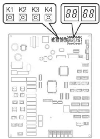
| K1 control KEY operation Display on segment | |
| Press and hold 1 time Auto trial operation | "K" "K" "BLANK" "BLANK"Display can be changed into "K" "9" "X" "X"(Last two digits display the progress.) |
| K1 (Number of press) KEY operation Display on segment | ||
| 1 time | Refrigerant charging in Heating mode | “K” “7” “BLANK” “BLANK” |
| 2 times Trial operation in Heating mode “K” “2” “BLANK” “BLANK” | ||
| 3 times | Pump out in Heating mode (Outdoor unit address 1) | “K” “3” “BLANK” “1” |
| 4 times | Pump out in Heating mode (Outdoor unit address 2) | “K” “3” “BLANK” “2” |
| 5 times | Pump out in Heating mode (Outdoor unit address 3) | “K” “3” “BLANK” “3” |
| 6 times | Pump out in Heating mode (Outdoor unit address 4) | “K” “3” “BLANK” “4” |
| 7 times | Vacuuming (Outdoor unit address 1) | “K” “4” “BLANK” “1” |
| 8 times | Vacuuming (Outdoor unit address 2) | “K” “4” “BLANK” “2” |
| 9 times | Vacuuming (Outdoor unit address 3) | “K” “4” “BLANK” “3” |
| 10 times | Vacuuming (Outdoor unit address 4) | “K” “4” “BLANK” “4” |
| 11 times | Vacuuming (All outdoor units) | “K” “4” “BLANK” “A” |
| 12 times | Inverter Fault Detection (Comp#1) | “K” “5” “1” “1” |
| 13 times | Inverter Fault Detection (Comp#2) | “K” “5” “1” “2” |
| 14 times | Inverter Fault Detection (Fan#1) | “K” “5” “F” “1” |
| 15 times | Inverter Fault Detection (Fan#2) | “K” “5” “F” “2” |
| 16 times | End Key operation | - |

WARNING
- After installing the product, be sure to perform leak tests on the piping connections. After pumping down refrigerant to inspect or relocate the outdoor unit, be sure to stop the compressor and then remove the connected pipes.
- Do not operate the compressor while a valve is open due to refrigerant leakage from a pipe or an unconnected or incorrectly connected pipe. Failure to do so may cause air to flow into the compressor and too a high pressure to develop inside the refrigerant circuit, leading to an explosion or product malfunction.
| K2 (Number of press) | KEY operation Display on segment | |
| 1 time | Refrigerant charging in Cooling mode | “K” “5” “BLANK” “BLANK” |
| 2 times Trial operation in Cooling mode | “K” “6” “BLANK” “BLANK” | |
| 3 times | Pump down all units in Cooling mode | “K” “7” “BLANK” “BLANK” |
| 4 times | H/R: Checking the pipe connectionH/P: Automatic setting of operation mode (Cooling/Heating) for trial operation | “K” “8” “BLANK” “BLANK” |
| 5 times Checking the amount of refrigerant | “K” “9” X X (Display of last two digits may differ depending on the progress) | |
| 6 times Discharge mode of DC link voltage | “K” “A” “BLANK” “BLANK” | |
| 7 times Forced defrost operation | “K” “B” “BLANK” “BLANK” | |
| 8 times | Forced oil collection | “K” “C” “BLANK” “BLANK” |
| 9 times | Inverter compressor1 check | “K” “D” “BLANK” “BLANK” |
| 10 times | Inverter compressor 2 check | “K” “E” “BLANK” “BLANK” |
| 11 times | Fan 1 check | “K” “F” “BLANK” “BLANK” |
| 12 times | Fan 2 check | “K” “G” “BLANK” “BLANK” |
| 13 times | H/R : Auto pipe pairingH/P : Unused | “K” “H” X X (Display of last two digits may differ depending on the progress) |
| 14 times | Baseheater testing mode | “K” “I” “BLANK” “BLANK” |
| 15 times | Unused | “K” “J” “BLANK” “BLANK” |
| 16 times | End Key operation | - |
※ Even when the outdoor unit power is off, it is dangerous when you come in contact with inverter PCB and fan PCB since they are charged with high DC voltage.
* When replacing/repairing the PCB, cut-off the power and wait until the DC voltage is discharged before replacing/repairing them. (Wait for more than 15 minutes to allow it to discharge naturally.)
※ When there were error, 'Discharge mode of DC link voltage' may not have been effective. Especially if error E464 and E364 have been occurred, power element might be damaged by fire and therefore, do not use the 'Discharge mode of DC link voltage'.
During "Discharge mode of DC link voltage", voltage of INV1 and INV2 will be displayed alternately. After discharging of DC link voltage, "K" "A" "o" "k" is displayed.
※ If "K" "A" "n" "A" is displayed or the voltage does not drop during "Discharge mode of DC link voltage", please cut-off the power and wait for 15 minutes until voltage discharges naturally. Due to the characteristics of the inverter PCB, "Discharge mode of DC link voltage" may not be supported.
※ When pressing K2 key 9 to 12 times without inverter checker, error code can be displayed on segment even though the outdoor unit is normal.
※ If error have been occurred, do not use the key operation.
※ If the 1st-generation MCU is installed, the Auto pipe pairing operation can not be used. If the 2nd-generation MCU is installed, the Checking the pipe connection can not be used.
- 1st-generation MCU : MCU-S*NEE*N, MCU-S2NEK1N
- 2nd-generation MCU : MCU-S*NEK2N, MCU-S4NEK3N, MCU-S1NEK1N
※ KEY operation of K215 times(Automatic refrigerant charging function) is an unused function. It can be available with Automatic refrigerant charging option KIT.
| K3 (Number of press) KEY operation Display on segment | |||
| 1 time | Initialize (Reset) setting | Same as initial state | |
| K4 (Number of press) KEY operation | Display on segment | ||
| SEG1 | SEG2, 3, 4 | ||
| 1 time | Capacity of Outdoor unit Model | 1 | (a) Capacity → Off, 1, 6 |
| 2 times | Order frequency of the compressor 1 | 2 | 120 Hz → 1, 2, 0 |
| 3 times | Order frequency of the compressor 2 | 3 | 120 Hz → 1, 2, 0 |
| 4 times | High pressure (MPa) | 4 | 1.52 MPa → 1, 5, 2 |
| 5 times | Low pressure (MPa) | 5 | 0.43 MPa → 0, 4, 3 |
| 6 times | Discharge temperature (Compressor 1) | 6 | 87 °C → 0, 8, 7 |
| 7 times | Discharge temperature (Compressor 2) | 7 | 87 °C → 0, 8, 7 |
| 8 times | IPM temperature (Compressor 1) | 8 | 87 °C → 0, 8, 7 |
| 9 times | IPM temperature (Compressor 2) | 9 | 87 °C → 0, 8, 7 |
| 10 times | CT sensor value (Compressor 1) | A | 2 A → 0, 2, 0 |
| 11 times | CT sensor value (Compressor 2) | B | 2 A → 0, 2, 0 |
English 51
Setting outdoor unit option switch and key function
| K4 (Number of press) KEY operation | Display on segment | ||
| SEG1 SEG2, 3, 4 | |||
| 12 times | Suction temperature | C | -42 °C → -, 4, 2 |
| 13 times | COND OUT temperature | D | -42 °C → -, 4, 2 |
| 14 times | Temperature of liquid pipe | E | -42 °C → -, 4, 2 |
| 15 times | TOP temperature (Compressor 1) | F | -42 °C → -, 4, 2 |
| 16 times | TOP temperature (Compressor 2) | G | -42 °C → -, 4, 2 |
| 17 times | Outdoor temperature | H | -42 °C → -, 4, 2 |
| 18 times | EVI inlet temperature | I | -42 °C → -, 4, 2 |
| 19 times | EVI outlet temperature | J | -42 °C → -, 4, 2 |
| 20 times | Main EEV1 step | K | 2000 steps → 2, 0, 0 |
| 21 times | Main EEV2 step | L | 2000 steps → 2, 0, 0 |
| 22 times | EVI EEV step | M | 300 steps → 3, 0, 0 |
| 23 times | HR EEV step | N | 300 steps → 3, 0, 0 |
| 24 times | Fan step (SSR or BLDC) | O | 13 steps → 0, 1, 3 |
| 25 times | Current frequency (Compressor 1) | P | 120 Hz → 1,2,0 |
| 26 times | Current frequency (Compressor 2) | Q | 120 Hz → 1,2,0 |
| 27 times | Suction 2 temperature | R | -42 °C → -, 4, 2 |
| 28 times | Main indoor unit address 5 | Main indoor unit not selected → BLANK, N, DIf indoor unit No.1 is selected as the main unit → 0, 0, 1 | |
| 29 times | unused | T | - |
| 30 times | Suction 3 temperature | U | -42°C → -, 4, 2 |
| 31 times | COND OUT 2 temperature | V | -42°C → -, 4, 2 |
| 32 times | End key operation | ||
※ Suction2 temperature is displayed on Heat Recovery or X-Large models.
※ Suction3 temperature & Cond out2 temperature are displayed on X-Large models.
(a) When pressing K4 key 1 time, below number is displayed on segment depending on model.
| Model | Display on segment |
| AM080*** | off, 0, 8 |
| AM100*** | off, 1, 0 |
| AM120*** | off, 1, 2 |
| AM140*** | off, 1, 4 |
| AM160*** | off, 1, 6 |
| AM180*** | off, 1, 8 |
| AM200*** | off, 2, 0 |
| Model | Display on segment |
| AM220*** | off, 2, 2 |
| AM240*** | off, 2, 4 |
| AM260*** | off, 2, 6 |
| AM280*** | off, 2, 8 |
| AM300*** | off, 3, 0 |
| AM320*** | off, 3, 2 |
| AM340*** | off, 3, 4 |
| K4 (Number of press)Press and hold the K4 to enter the setting | Displayed content | Display on segment | |||
| page1 | page2 | ||||
| 1 time | Main version | MAIN | Version (ex. 1412) | ||
| 2 times | Hub version | HUB | Version (ex. 1412) | ||
| 3 times | Inverter1 version | INV1 | Version (ex. 1412) | ||
| 4 times | Inverter 2 version | INV2 | Version (ex. 1412) | ||
| 5 times | Fan 1 version | FAN1 | Version (ex. 1412) | ||
| 6 times | Fan 2 version | FAN2 | Version (ex. 1412) | ||
| 7 times | EEP version | EEP | Version (ex. 1412) | ||
| 8 times | Automatically assigned address of the units | AUTO | SEG1 | SEG2 | SEG3, 4 |
| Indoor unit: "A"MCU: "C" | Indoor unit: "0"MCU: "1" | Address(ex: 07) | |||
| 9 times | Manually assigned address of the units | MANU | SEG1 | SEG2 | SEG3, 4 |
| Indoor unit: "A" | Indoor unit: "0" | Address(ex: 15) | |||
※ I/U : Indoor unit
Performing final checks and trial operation
1 Before supplying the power, use DC 500V (AM****XV*J*) or DC 600 V (AM****XV*F*) insulation resistance tester to measure the power (3 phase: R, S, T/1 phase: L, N) terminal and the outdoor unit grounding.
- Measurement should be over 30MΩ.
2 Before supplying the power, use a voltmeter and phase tester to check the voltage and the phase.
- R, S, T terminal: Check the 460V (AM****XV*J*) or 230V (AM****XV*F*) between wires (R-S, S-T, T-R)

CAUTION
- Never measure the communication terminal since communication circuit may get damaged.
- Check for short-circuit of the communication terminal with a general circuit tester.
![[AM***XV*J*] 460V 460V 460V T S R < ELB >](/content/2026/05/1065471/images/313c21248f7cb17c9767251ef6cf181d4b23bdea0e49d5533fb5e4aac6ee6609.jpg)
![[AM* * * * XV* F*] 230V 230V 230V T S R < ELB >](/content/2026/05/1065471/images/400a222bb58df8b26cc0aa66c3705c153005a8354574f47718da08192fc5521e.jpg)
3 Check if the R-410A indoor units are connected.
4 When N phase is not correctly connected to R, S and T phase, over-voltage protection control will be in effect and it will cut-off the power of the PCB. Check the power cable connection of the N phase if the PCB is not turned on.
5 Check the following after the installation is completed.
| Installation work | Outdoor unit | Have you checked the external surface and the inside of the outdoor unit?Is there any possibility of short-circuit caused by the heat of an outdoor unit?Is the place well-ventilated and ensures space for service?Is the outdoor unit fixed securely to withstand any external force? |
| Indoor unit | Have you checked the external surface and the inside of the indoor unit?Is there enough space for service?Have you checked if the center of the indoor unit is ensured and it is installed horizontally? | |
| Refrigerant pipe work | Have you selected correct pipes?Are the liquid and gas valve open?Is the total number of connected indoor units within the allowable range?Are the length and the height difference between the refrigerant pipes within the allowable range?Are the branch joints properly installed?Did you check the connection of liquid and gas pipes?Have you selected correct insulator for pipes and insulated them correctly?Did you insulate the pipes and connection part correctly?Is the quantity of the additional refrigerant correctly weighed in? (You must record the amount of additional refrigerant on the service record paper placed inside of the outdoor unit.) | |
| Drain pipe work | Have you checked if the drain pipes of the indoor and outdoor unit are connected together?Have you completed the drain test?Is the drain pipe properly insulated? | |
| Electrical wiring work | Are the power cable and communication cable tightened firmly on the terminal board within the range of rated tightening torque?Have you checked for cross-connection of the power and communication cables?Have you performed the earthing work 3 to the outdoor unit?Did you make sure to use 2-core cable (not multi-core cable) for the communication cable?Is the length of the wire within allowed range?Is the wiring route correct? | |
| Setting address | Did you set the address of the indoor and outdoor units properly?Did you set the address of the indoor and outdoor units properly? (When using multiple remote controllers) | |
| Option | If there is a possibility of the outdoor unit from vibrating, check whether the anti-vibration frame is correctly installed. | |
English 53
Performing final checks and trial operation

CAUTION
Precautions before test operation
- When the outdoor temperature is low, turn on the main power 6 hours before beginning the operation.
- If you start the operation immediately after turning on the main power, it may cause serious damage to the part in the product.
- Do not touch the refrigerant pipe during or right after the operation.
- Refrigerant pipe may be hot or cold during or right after the operation depending on the status of the refrigerant which flows through the refrigerant pipe, compressor and other parts of the refrigerant cycle.
- Do not operate the product with its panel or protection nets off. - There is risk of personal injury from the parts rotating, heated or with the high voltage.
- Do not turn off the main power immediately after stopping the operation.
- Wait for at least 5 minutes before turning off the main power. If not, water leakage or other problems may occur.
- Connect all the indoor units and the power supply for the outdoor unit and run auto address setting. Run auto address setting even after changing the indoor unit PCB.
Checklist before auto trial operation
1 Check the power cable and communication cable of the indoor and outdoor unit.
2 Supply power to the outdoor unit 6 hours before trial operation to pre-heat the compressor.
3 Before supplying the power, use a voltmeter and phase tester to check the voltage and the phase.
- R,S,T terminal: check the 460V between wires (R-S, S-T, T-R) (AM****XV*J* Model only) / 230V between wires (R-S, S-T, T-R) (AM****XV*F* Model only).
4 When the power is supplied, outdoor unit will execute tracking to check the indoor unit connection and other optional functions.
5 Write down the installation report on the service history report paper attached on the front part of the control box.

CAUTION
• Supply power to the outdoor unit 6 hours before auto trial operation to pre-heat the compressor.
6 Guaranteed range of auto trial operation For precise judgment, you must perform auto trial operation in below indoor/outdoor temperature condition.
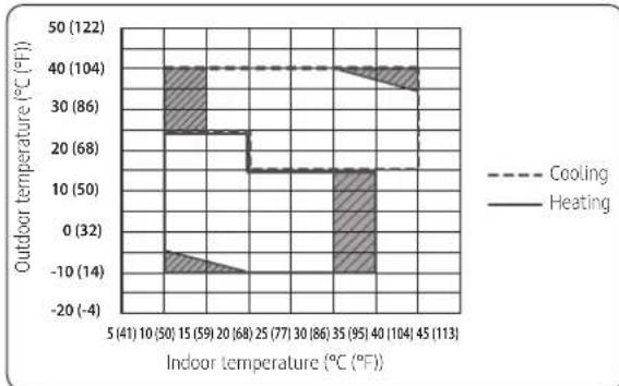
bar_line
| Indoor temperature (°C (°F)) | Outdoor temperature (°C (°F)) | |---|---| | 5 (41) | 40 (104) | | 10 (50) | -10 (14) | | 15 (59) | 20 (68) | | 20 (68) | 30 (86) | | 25 (77) | 20 (68) | | 30 (86) | 10 (50) | | 35 (95) | 10 (50) | | 40 (104) | 40 (104) | | 45 (113) | 40 (104) |- In Auto trial operation, product will automatically select either cooling or heating mode and operate in selected mode.
- In the temperature range marked with slashed pattern, system protection control may trigger during operation.(If the system protection control is enabled, it can be hard to get the precise judgment after the auto trial operation.)
- When the temperature is outside of guaranteed range, accuracy of judgment on auto trial operation may decrease near boarder line area.
- If all indoor units are connected with only hydro unit, it is operated by heating mode. If outdoor temperature is above 35^ (95°F), auto trial operation is skipped and UP mode will be cleared.
Auto trial operation
1 If the Auto Trial Operation is not completed, normal operation will be prohibited.
- When the auto trial operation is not completed, UP (UnPrepared) will appear on the segment after the communication check and restrict compressor from operating. (UP Mode will be cleared automatically when auto trial mode is completed.)
- Auto trial operation may take 20 minutes to maximum 2 hours depending on the operation status.
– During auto trial operation, noise can be generated due to valve inspection. (Check the product if abnormal noise occurs continuously)
2 When error occurs during auto trial operation, check the error code and take appropriate measures.
- Refer to next couple of pages when E503, E505 or E506 error occurs.
3 When auto trial operation ends, use S-NET pro or S-CHECKER to issue a result report.
- Refer to service manual if you have any items with "NG" on the result report.
- After taking appropriate measure for the items with "NG", run the auto trial operation again.
4 Check the following items by running trial operation (cooling/heating).
- Check if cooling/heating operation performs normally.
- Individual indoor unit control: Check for air flow direction and fan speed.
- Check for abnormal operation noise from the indoor and outdoor unit.
- Check for proper draining from the indoor unit during cooling operation.
- Use S-NET pro to check the detail operation status.
5 Explain to the user how to use the air conditioner according to the user's manual.
6 Hand over the installation manual to the customer so they can keep it with them.

CAUTION
- Make sure to close the top and bottom part of the outdoor unit cabinet during operation. If you operate the unit with the front cabinet open, it may cause damage to the product and you may not get the precise data from S-NET pro.
Inspection and trial operation
Measure to take when E503 error occurs
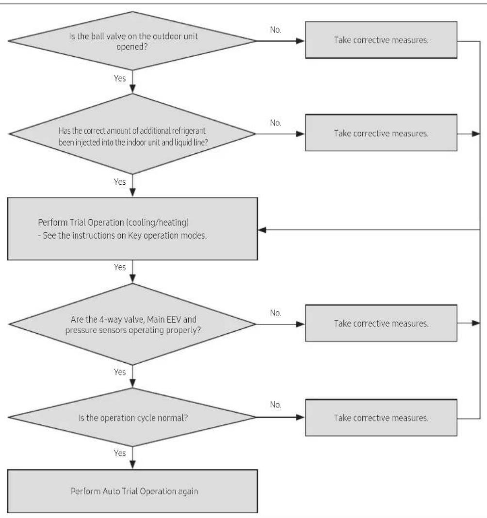
flowchart
graph TD
    A{Is the ball valve on the outdoor unit opened?}
    B{Has the correct amount of additional refrigerant been injected into the indoor unit and liquid line?}
    C["Perform Trial Operation (cooling/heating)<br>- See the instructions on Key operation modes."] -->|Yes| D{Are the 4-way valve, Main EEV and pressure sensors operating properly?}
    E["Perform Auto Trial Operation again"] -->|No| F["Take corrective measures."]
    F --> G{Is the operation cycle normal?}
    G -->|Yes| D
    G -->|No| H["Take corrective measures."]
    H --> I["Take corrective measures."]
    I --> J{Has correct amount of additional refrigerant been injected into the indoor unit and liquid line?}
    J -->|Yes| K["Perform Trial Operation (cooling/heating)<br>- See the instructions on Key operation modes."]
    J -->|No| L["Take corrective measures."]
    L --> M{Are the 4-way valve, Main EEV and pressure sensors operating properly?}
    M -->|Yes| N["Perform Auto Trial Operation again"]
    M -->|No| O["Take corrective measures."]
    O --> P["Take corrective measures."]
    P --> Q{Is the operation cycle normal?}
    Q -->|Yes| R["Perform Auto Trial Operation again"]
    Q -->|No| S["Take corrective measures."]
※ Symptoms for abnormal operation of the 4way valve
- Abnormal noise during compressor operation, Increase in the suction temperature.
※ Symptoms for abnormal operation of the Main EEV
- It is not possible to control the superheat (SH)
- It is not possible to secure a DSH of higher than 20K
※ For more information, see the troubleshooting in the service manual.
CAUTION
- If service valve (ball valve) check is required, corresponding outdoor unit will display the error.
- If service valve (ball valve) check is required, auto detection mode will be terminated. Check service valve (ball valve) of gas pipe and liquid pipe at the same time when checking service valve (ball valve).
- When 4way valve, Main EEV detection is needed, run heating trial operation for more than 1 hour and analyze the data to check for a problem.
- If there's frost formed in outdoor unit or the outdoor unit is operating in defrost operation, it may be hard to detect problem normally. In this case, perform Trial operation or Forced defrost operation to eliminate the frost, and then perform Auto Trial Operation again.
- If the operation range is not within guaranteed range, error may occur even though the product is normal.
- To replace a component or inspect the PBA, be sure to cut off the power supply first. If inspection must be performed with the power supply on, exercise extra care to prevent electric shock.
English 55
Inspection and trial operation
Measure to take when E505 or E506 error occurs
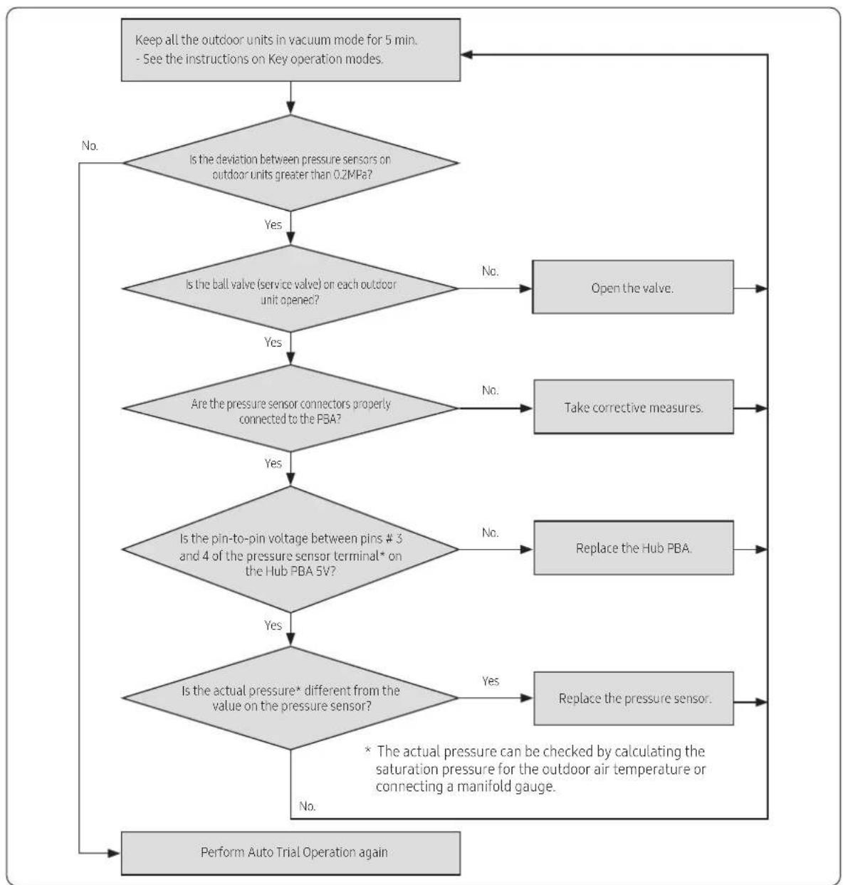
flowchart
graph TD
    A["Keep all the outdoor units in vacuum mode for 5 min.<br>- See the instructions on Key operation modes."] --> B{Is the deviation between pressure sensors on outdoor units greater than 0.2MPa?}
    B -->|No.| C["Perform Auto Trial Operation again"]
    B -->|Yes.| D{Is the ball valve (service valve) on each outdoor unit opened?}
    D -->|Yes| E{Are the pressure sensor connectors properly connected to the PBA?}
    D -->|No.| F["Open the valve."]
    E -->|Yes| G{Is the pin-to-pin voltage between pins # 3 and 4 of the pressure sensor terminal* on the Hub PBA 5V?}
    E -->|No.| H["Take corrective measures."]
    G -->|Yes| I{Is the actual pressure* different from the value on the pressure sensor?}
    G -->|No.| J["Replace the Hub PBA."]
    I -->|Yes| K["Replace the pressure sensor."]
    I -->|No.| L["The actual pressure can be checked by calculating the saturation pressure for the outdoor air temperature or connecting a manifold gauge."]
    K --> M["End"]
※ For more information, see the troubleshooting in the service manual.

CAUTION
- When the auto trial operation for pressure sensor was executed before the pressure of the outdoor unit is equalized (when there's close to no difference between high and low pressure), error may occur even though the product is normal.
- If pressure sensor check is required, error will be displayed on all installed outdoor units.
- If pressure sensor check is required, outdoor units will terminate auto trial operation mode automatically.
- To check for the pressure sensor with the problem, run trial operation for more than 1 hour and analyze the data to check for a problem.
- To replace a component or inspect the PBA, be sure to cut off the power supply first. If inspection must be performed with the power supply on, exercise extra care to prevent electric shock.
Automatic refrigerant amount detection function
This function checks amount of refrigerant in the system through refrigerant amount detection operation
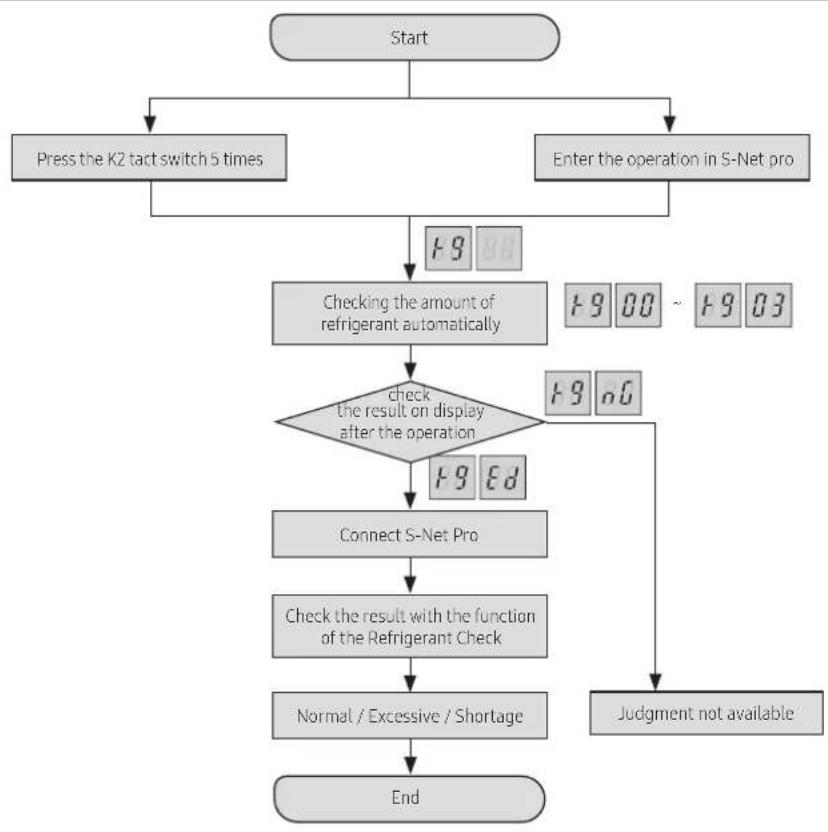
flowchart
graph TD
    A["Start"] --> B["Press the K2 tact switch 5 times"]
    A --> C["Enter the operation in S-Net pro"]
    B --> D{19.00}
    C --> E{19.00 ~ 19.03}
    D --> F["Checking the amount of refrigerant automatically"]
    F --> G{check the result on display after the operation}
    G -->|19.00| H["Connect S-Net Pro"]
    G -->|19.00| I["Judgment not available"]
    H --> J["Check the result with the function of the Refrigerant Check"]
    J --> K["Normal / Excessive / Shortage"]
    K --> L["End"]
* After refrigerant amount detection is finished, if you see "K9 Ed" on the display and cannot check the refrigerant amount from the S-net pro and S-checker, it means insufficient degree of supercooling.

CAUTION
- If the temperature is out of the guaranteed range below, exact result will not be obtained.
- Indoor: 20\~32 °C (68\~89.6 °F)
- Outdoor: 5\~43 °C (41\~109.4°F)
- If the operation cycle is not stable, the operation of refrigerant amount check may be forcibly finished.
- Accuracy of the result may decrease if the product has not been operated for a long period of time or Heat mode has been operated before running the function of refrigerant amount check. Therefore, use the function of refrigerant amount check after operating the product in Cool mode for at least 30 minutes.
- Product may trigger system protection operation depending on the installation environment. In this case, the result of refrigerant amount check may not be accurate.
Actions to take for the check result
• Excessive amount of refrigerant
- Discharge 10% of total amount of refrigerant and restart the refrigerant amount check.
• Insufficient amount of refrigerant
- Add 10% of the total amount of refrigerant and restart the refrigerant amount check.
• Judgment not available
- Check if the function of refrigerant amount check is executed within the guaranteed temperature range. Run trial operation to check if there are other problems on the system.
English 57


SAMSUNG


- Contents
- Safety Information 3
- Installation Procedure 5
- Appendix 55
- English
- Safety Information
- WARNING
- CAUTION
- General information
- Preparations for Outdoor Unit
- Moving the outdoor unit
- When moving with a crane
- When moving with a forklift
- When moving the product without wooden pallet and the crane is not available for use
- Outdoor unit combination
- Choosing the installation location
- Outdoor unit location requirements
- Installation Guide at the seashore
- Outdoor unit space requirements
- Preparing materials and tools
- Optional accessories
- Outdoor unit installation
- Examples of draining work
- Installing the outdoor unit in various environments
- Installing the outdoor unit around the obstacles
- Installing the outdoor unit in cold region
- Installing the outdoor unit in windy region
- Refrigerant pipe installation
- Refrigerant pipe work
- Selecting refrigerant pipe
- Size of the pipe between branch joints (B)
- Size of the pipe between the branch joint and the indoor unit (F)
- Additional refrigerant
- Temper grade and minimum thickness of the refrigerant pipe
- Keeping refrigerant pipe
- Refrigerant pipe welding and safety information
- Nitrogen flushing welding
- Direction of the pipe when welding
- Cutting or flaring the pipes
- Connecting the flared pipes
- Pipe installation for an outdoor unit
- Examples of refrigerant pipe installation
- Installing the branch joints
- NOTE
- Installing the distribution header
- Installing the branch joint between outdoor units
- Electrical wiring work
- Power and communication cable configuration
- Selecting solderless ring terminal
- Connecting the power terminal
- Examples of how to use the cable striper
- Fixing the power cable
- Connect the ring terminal of 3 phase cable
- Fixing the ground cable
- Withdrawing the power cable
- Installing the Solution device
- Where to install the interface module
- Grounding work
- Grounding the power cable
- Performing the grounding work
- Air tightness test and vacuum drying
- Air tightness test
- Vacuum drying pipes and indoor units
- Pipe insulation
- Insulating the refrigerant pipes and branch joints
- Selecting the refrigerant pipe insulator
- Insulate the refrigerant pipe
- Insulating pipes
- Insulating pipes connected behind the EEV kit
- Insulate the distribution header
- Insulating the branch joint
- Insulating the pipe located inside of the outdoor unit
- Single installation
- Module installation
- Using service valve for gas
- Basic segment display
- Setting outdoor unit option switch and key function
- Setting outdoor unit option switches
- Installing and setting the option with tact switch and explanation of the functions
- Setting the option
- Performing final checks and trial operation
- Checklist before auto trial operation
- Auto trial operation
- Inspection and trial operation
- Automatic refrigerant amount detection function
- SAMSUNG
Brand : SAMSUNG
Model : AM180CXVAFH
Category : Séparateur