EX-100A - Lamp Impact - Free user manual and instructions
Find the device manual for free EX-100A Impact in PDF.


| Product Type | Monolight (studio flash unit) |
| Model | Impact EX-100A |
| Power Output | 100 W/s |
| Guide Number | 30 (with included reflector, ISO 100, 10 ft) |
| Output Control Range | Full to 1/8 power, stepless |
| Recycling Time | 1–2 seconds |
| Flash Duration | 1/1000 – 1/1500 second |
| Flash Ready Indicator | LED and audible beep |
| Modeling Lamp | 60W (max 100W), can be set to proportional or full power |
| Trigger Methods | Sync cable, built-in optical slave, test button |
| Trigger Voltage | 4.3V (safe for all cameras) |
| Color Temperature | 5800°K ±200°K |
| Reflector Mount | Elinchrom-style (accepts accessories, 8-inch grid reflector included) |
| Sync Connection | 1/8 inch mini-plug jack |
| Power Source | 110–120V AC, 60Hz (US model) or 220V AC (Europe model) |
| Circuit Protection | 6.3A fuse (user-replaceable, spare included) |
| Dimensions (without reflector) | 9.5 × 7.75 × 5 in (240 × 198 × 127 mm) |
| Dimensions (with reflector) | 11.25 × 8.25 × 10.3 in (285 × 210 × 262 mm) |
| Weight | 2.6 lb (1.2 kg) |
| Included Accessories | Protective cap, flashtube, 60W modeling lamp, 8" grid reflector, sync cable, spare fuse, power cable, user manual |
| Warranty | One year limited warranty (parts and labor) |
Frequently Asked Questions - EX-100A Impact
User questions about EX-100A Impact
0 question about this device. Answer the ones you know or ask your own.
Ask a new question about this device
Download the instructions for your Lamp in PDF format for free! Find your manual EX-100A - Impact and take your electronic device back in hand. On this page are published all the documents necessary for the use of your device. EX-100A by Impact.
USER MANUAL EX-100A Impact
natural_image
Black megaphone with white lens against yellow background (no text or symbols visible)EX-100A Monolight
INSTRUCTIONS
Thank you for your purchase of the Impact EX-100A Monolight. The EX-100A Monolight is economical and lightweight, yet durable enough to give you many years of trouble-free service and enjoyment. Please read these operating instructions and safety precautions carefully before operating this equipment.
Features
- Three-stop range – full power to 1/8 power, steplessly
• Built-in optical slave - Modeling lamp can be set to proportional or full power
- Accepts Elinchrom-style reflectors and head accessories (8-inch grid reflector included)
- Tactile, "grippy" feel that resists slipping, scratches, and shock damage
- Commonly available 1/8" mini-plug sync input
- Low 4.3V trigger voltage – safe for any camera's circuitry
Power Requirements
This light comes in two models; one is designed for use with 110/120V AC power in the US and the other for 220V AC power in Europe. Neither model can be used outside of its native power region. Both are supplied with a three-prong, grounded plug. Do not attempt to defeat this safety feature. If necessary, use only grounded extension cords rated for six amps or greater.
Warning
There are no user-serviceable parts inside the unit. Only qualified service engineers should access the inside of the case (Danger – high-voltage parts inside). Avoid damage to both the flashtube and modeling lamp. If the modeling lamp or flashtube become cracked or damaged in any way, they should be replaced immediately. Do not use your flash unit in an environment where moisture or flammable vapor is likely to come in contact with the unit. Turn the power off and unplug the power cord when the unit is not in use. Always remove the modeling lamp and replace the protective cap when transporting the unit. Avoid strong light falling onto the slave cell as it will prevent efficient operation. If the unit blows a fuse, a replacement fuse can be inserted in the pull-out compartment on the back of the unit. To ensure long life of the flash capacitors, the flash unit should be powered up and fired several times at least every two months.
Preparing Your Monolight for Use
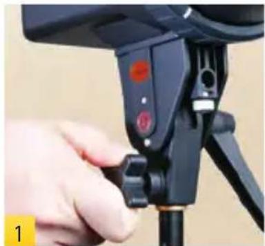
Mount on a stand
(1) Select a stand or support system of suitable weight and dimensions to ensure stable operation of the unit.
Install Reflector & Modeling Lamp
(2) Remove the protective cap by pressing in and turning it counterclockwise. Pull the cap off and set aside.
(3) Install the modeling lamp by screwing it into the threaded socket.
natural_image
Close-up of a hand adjusting a black tripod-mounted camera mount with adjustment knobs (no visible text or symbols)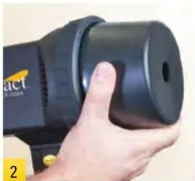
natural_image
Close-up of a hand holding a black handheld device with a circular button, no visible text or symbols on the device itself.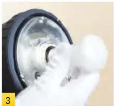
natural_image
Close-up of a mechanical component with white foam and a black plastic housing (no visible text or symbols)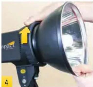
natural_image
Close-up of a black compact camera lens being held, with yellow arrow indicating light direction (no text or symbols visible)CAUTION: Do not touch the lamp with your bare hands. Oil residue from your fingers can cause the surface of the lamp to heat unevenly and explode. Use white cotton gloves or a clean cloth.
(4) Install the reflector where the protective cap was before. Align the two notches on the reflector with the white guidelines on the flash unit, press the reflector in and rotate clockwise until it locks in place. Rotate the outer ring to secure the reflector.
Note: Take care when fitting or removing reflectors or softboxes to not damage the flashtube assembly. The flashtube is very delicate. Always switch off the unit and disconnect the power before fitting or changing lamps, flashtubes, reflectors, or softboxes.
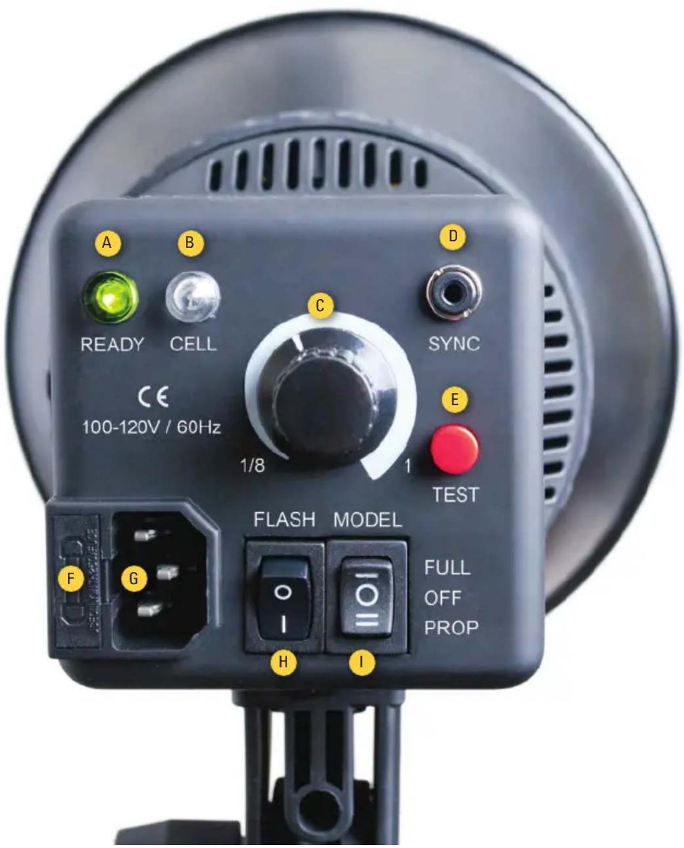
Operating Instructions
Legend
A – Recycle Indicator Light F – Fuse Holder
B - Photocell G - Power Socket
C – Power Regulator Dial H – On/Off Switch
D - Sync Jack I - Modeling Light Switch
E - Test Fire Button
Power Supply
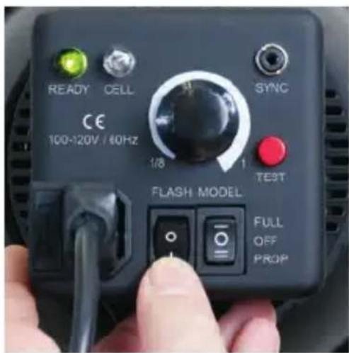
Plug the power cord into the back of the flash unit. Before plugging the power cord into the wall socket, make certain that the power switch is set to the OFF (circle) position.
Note: The EX-100A flash unit comes in two designs; one is designed for use with 110/120V AC power in the US and the other for use with 220V AC power in Europe. Neither model can be used outside of its native power region.
Power Switch
Turn the power switch to the ON (line) position. The flash will sound a beep and then sound a second beep indicating that flash power has been reached and the unit is ready to fire. The green ready light will also be lit. We recommend charging the flash unit for one hour prior to its initial use and after an extended period of inactivity (more than two weeks). If the unit is left unused for a few months, or the unit has been used predominantly at low power settings, we recommend that the power be increased to the maximum and the unit left switched on (with the modeling lamp OFF) for at least 30 minutes, with several test flashes fired, to help preserve the life of the capacitors.
Flash Settings
Flash Output
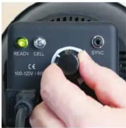
The flash power output is variable over a three f/stop range (four f/stops) from full power to 1/8 power in a stepless gradation. Flash power is adjusted by rotating the power-regulator knob on the back panel of the unit. The EX-100A will sound a beep and the green indicator will light when the unit has recycled and is ready to flash.
Lowering Flash Power
While raising the flash power requires no special consideration, lowering the power does. Excess power that has built up in the system's capacitors must be released. You must press the red test button to manually "pop" the flash after a power-lowering adjustment. The EX-100A will then recycle to the lower power you've selected. A beep will sound and the green indicator will light when the unit has recycled and is ready to flash again.
Caution: To avoid eye damage, do not look into the strobe while firing. Do not fire the flash in close proximity to the face. Turn the unit off and unplug the power cord when changing attachments.
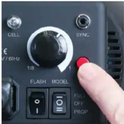
Manually "pop" the flash when reducing flash power. This will flush the excess power in the capacitors.
Modeling Light Settings
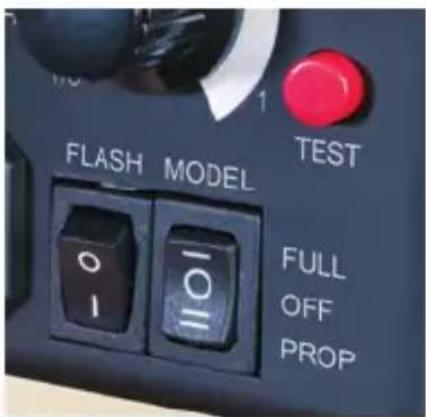
The Modeling Light switch is to the right of the power switch and has three settings: Proportional Mode, Full Power, and Off.
Proportional Mode
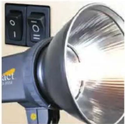
During normal use, most photographers will use a monolight in “Proportional” Mode. The modeling light intensity will increase or decrease in response to changes in the flash power. To work in Proportional Mode, rock the modeling light switch so that bottom of the switch (marked with double horizontal lines) is down.
Full Power
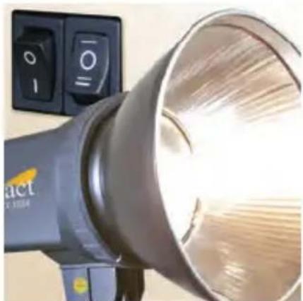
The EX-100A allows you to reduce the flash power but keep your modeling light at full power. Rock the modeling light switch so that the top of the switch (marked with a single horizontal line) is down. The modeling light will stay on at its full power.
Off
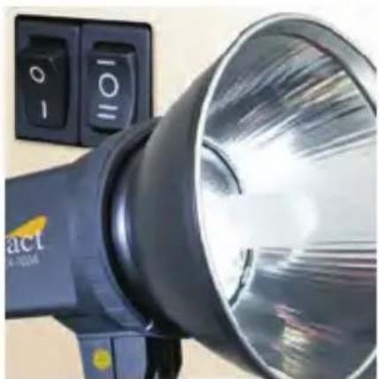
To turn off the modeling light, set the modeling light switch to its middle position (marked with an "O").
natural_image
Close-up of a black handheld light bulb with control buttons, no visible text or symbols on the bulb itself.Modeling light and flash power are proportional
natural_image
Close-up of a black and silver handheld light bulb with control buttons, no visible text or symbols on the bulb itself.Modeling light set to full power
natural_image
Close-up of a black compact light bulb with control buttons, no visible text or symbols on the bulb itself.Modeling light is off
Triggering the Flash
TEST Button
There are three ways to trigger your flash, but the simplest is to press the red TEST button. This is useful when you need to discharge the power built up in the flash unit, for example, just before replacing the flashtube (more on that later).
Sync Connection
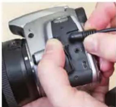
The sync jack on the EX-100A Monolight may be used for direct connection to a camera set to 'X' synchronization. Insert the "PC" end of the supplied sync cord into the connection on your camera and the other mini-plug end into the sync jack on the back panel of the EX-100A. A radio slave receiver with a mini-plug may also be plugged into this jack.
Photo Cell
The EX-100A Monolight features a photo cell which allows the flash unit to be triggered by another flash. This is called “Slave Mode.” The photo cell is located on the back panel next to the ready light. The photo cell is very sensitive, but some experimentation with positioning may be necessary to ensure a reliable trigger, particularly if the cell is not in the direct line of sight of the triggering flash unit. Avoid directly illuminating the photo cell from a continuous light source (such as ceiling lights or windows) since this can prevent correct operation. Very high ceilings can also affect the operation of the photo cell.
The EX-100A is always in Slave Mode, even when using sync cords. To disable the photo cell, cover both the ready and photo cell sensors with black electrical tape.
natural_image
Close-up of hands using a camera to adjust the lens (no visible text or symbols)Sync connection: step 1
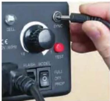
Sync connection: step 2
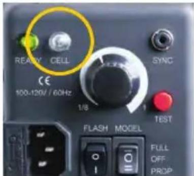
The photo cell sensor
Use of Umbrellas
natural_image
Person using a Impact camera to adjust the lens (no visible text or symbols)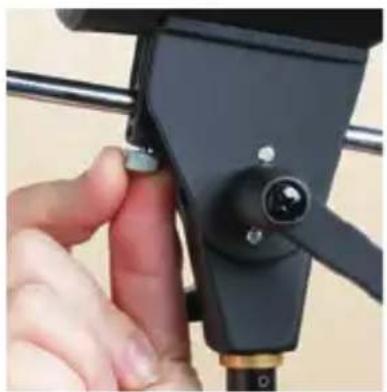
natural_image
Close-up of a hand adjusting a black camera lens mounted on a tripod stand (no visible text or symbols)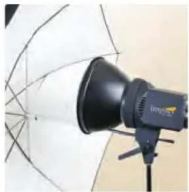
natural_image
Photography studio lighting equipment with a black megaphone and white umbrella (no visible text or symbols)Umbrellas
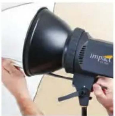
An umbrella with a handle diameter of up to 9mm can be secured in the umbrella holder. Firmly press the umbrella shaft through the holder. The locking knob is located beneath the holder. Do not overtighten to avoid damaging the shaft of the umbrella. The reflector supplied with the Impact EX-100A features a slot through which you can feed the umbrella shaft. Be sure to install the reflector with the slot at the bottom.
Use of Softboxes
The EX-100A Monolight is often sold as a kit with an Impact softbox included. The following instructions will guide you to set up the Impact softbox typically included in an EX-100A kit. If you bought the EX-100A alone, you can use any softbox that has an Elinchrom mount.
natural_image
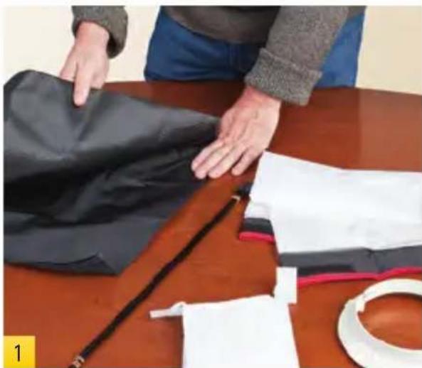
Person folding a black fabric on a wooden table with scissors and paper nearby (no text or symbols visible)Begin by unfolding the softbox skin.
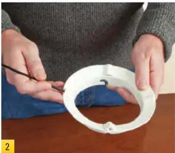
Remove the rubber bands holding the flex rods together.
natural_image
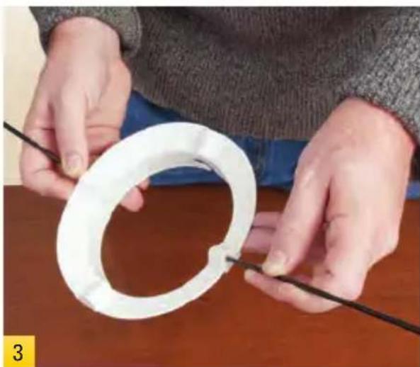
Person holding a white circular object with a black tool, placed on a wooden table (no text or symbols visible)Insert the small end of one of the flex rods into the mounting ring. Be certain to insert the rod as far as it will go.
natural_image
Person assembling a white plastic ring with black wires (no text or symbols visible)Insert a second flex rod in the hole opposite the first one.

natural_image
Close-up of hands holding a white plastic helmet with a yellow 'impact' logo on the sleeve (no other text or symbols visible)Pull the softbox skin over the mounting ring. Align the corners with the flex rods.
natural_image
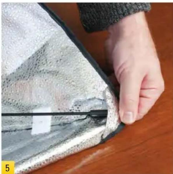
Close-up of a hand holding a transparent glass panel over a dark surface, with no visible text or symbols.Tuck the thick end of one of the flex rods into a pocket in the corner of the softbox skin.
natural_image
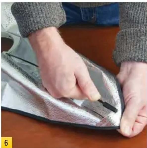
Close-up of hands using a tool to cut a metallic object with a black clip, placed on a wooden surface (no text or symbols visible)Tuck the opposite flex rod into its pocket. You'll have to bend the rod a little to get it to fit.
natural_image
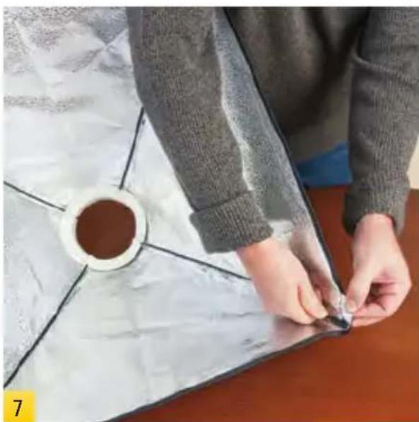
Person assembling a patterned fabric with a circular container nearby (no visible text or symbols)Continue with the third and fourth flex rods, inserting the small ends all the way into the mounting ring first.
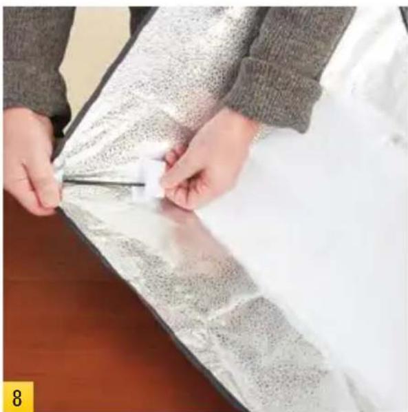
natural_image
Person cutting through a patterned plastic sheet with scissors, no visible text or symbolsThe interior baffle attaches with touch fasteners. You can leave this baffle off for more intense light.
Use of Softboxes (Continued)
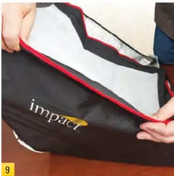
The front diffuser attaches to touch fasteners on the outside edge of the softbox skin.
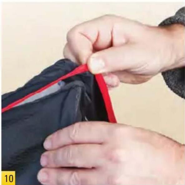
natural_image
Close-up of hands adjusting a red fabric piece on a dark garment (no text or symbols visible)After you've attached the touch fasteners on all four sides, pull the corners of the diffuser over the corners of the softbox.
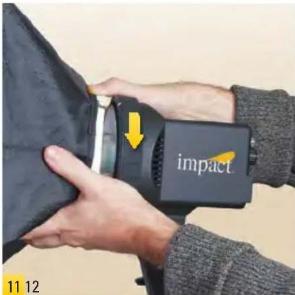
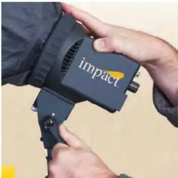
Mount your softbox onto the monolight. Line up the notches with the white marks, push in and turn clockwise until it locks.
natural_image
Person adjusting a Impact camera lens with black frame (no visible text or symbols on device)You're ready to shoot. You can angle the softbox by releasing the locking arm. Adjust positioning, then lock it back down.
Breaking Down Your Softbox
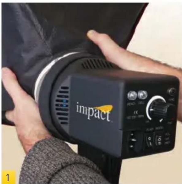
natural_image
Close-up of hands holding a black compact camera with 'impact' branding, no visible text or symbols on the device itself.Turn off the power to your light head and disconnect the power supply. Unmount the softbox assembly from the monolight.
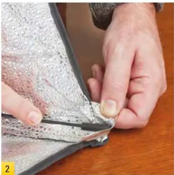
natural_image
Close-up of hands folding a metallic fabric or leather piece on a wooden surface (no text or symbols visible)Remove both diffusers. Release a flex rod by folding the corner of the softbox away from its captured rod.
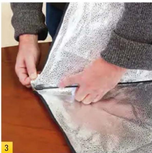
natural_image
Person handling a transparent plastic sheet over a dark surface, no visible text or symbolsThe second rod to be released should be the one opposite the first. Continue with the third and fourth flex rods.
natural_image
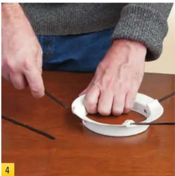
Person using a white plastic device to cut or wire around a table with black wires (no text or symbols visible)Pull the flex rods from the mounting ring. Stow everything until the next shoot.
Changing the Flashtube
Discharge the Flash Unit
The charge in the flash unit must be discharged before removing the flashtube. Make sure the flash unit is on. Push the TEST button on the rear panel of the flash. The unit will flash, discharging the power. Immediately turn off the power switch on the rear panel. Unplug the power cord from the power source. It is advisable to wait at least 30 minutes before touching or removing the flashtube.
natural_image
Close-up of a gloved hand holding a small mechanical component, possibly a pump or motor (no visible text or symbols)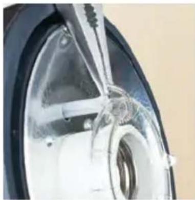
natural_image
Close-up of a jet engine wheel rim and fuselage (no visible text or symbols)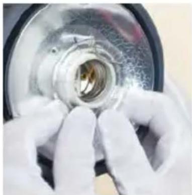
natural_image
Close-up of gloved hands holding a metallic mechanical component (no visible text or symbols)Remove Old Flashtube
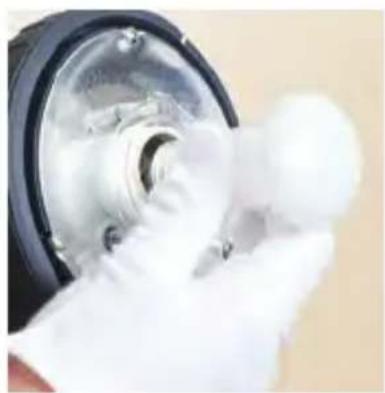
First, remove any reflector, softbox, or flash head accessory. Then, using white cotton gloves or a clean cloth, remove the modeling lamp. You will need to remove the retention spring wrapped around the top of the flashtube. With needle-nose pliers, unhook the retention spring loop. Using white cotton gloves or a clean cloth, grip the base of the flashtube on each side. Carefully pull the flashtube from the flash unit.
Install New Flashtube
Make sure the power switch is off and the power cord is disconnected from the outlet. Locate the two flashtube pin sockets above the modeling lamp socket. Using white cotton gloves or a clean cloth, push the pins of the flashtube into the sockets using firm, even pressure at the base of the flashtube. With needle-nose pliers, hook the retention spring over the hook above the flashtube. Reinsert the modeling lamp using white cotton gloves or a clean cloth. Reinstall the reflector.
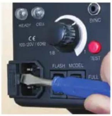
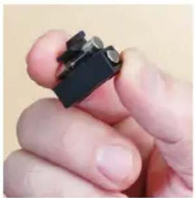
A 6.3A fuse is mounted in the rear panel and protects the circuitry of the flash unit. Turn off the unit and disconnect the power supply before changing the fuse. Never replace with a fuse of a different type or rating. A spare 6.3A fuse has been included with your EX-100A monolight. Use a small screwdriver to release the fuse cover. Remove the old fuse, place the new fuse in the slot, then replace the fuse holder.
natural_image
Close-up of a hand holding a small black electronic component (no visible text or symbols)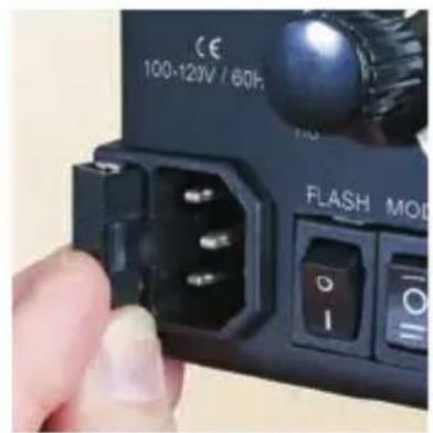
Safety and Maintenance Notes
Safety Notes
- Do not use your flash in an environment where moisture may come in contact with the unit.
- A fire hazard exists if flammable materials are placed in close proximity to the flashtube or the modeling lamp. Do not use your flash in an environment where flammable vapors are present.
- Do not restrict the ventilation holes when the flash is in use.
- Always switch off the power and disconnect the power cord before changing the fuse, modeling lamp, or flashtube.
- Avoid placing cables where they can be tripped over. Replace damaged cords immediately.
- Never use a flash unit with damaged covers, moldings, flashtube, or modeling lamp. If the unit is dropped or damaged, have it checked by a professional repair service before using.
- Due to the high-voltage circuitry inside this device, do not attempt to disassemble or repair the unit yourself.
- Keep out of the reach of children.
Maintenance Notes
- Turn the power off and unplug the power cord when the flash is not in use.
- We recommend charging the flash unit for one to two hours prior to its initial use and after an extended period of inactivity (more than two weeks).
- If the unit is left unused for a few months, or the unit has been used predominantly at low power settings, we recommend that the power be increased to the maximum and the unit left switched on (with the modeling lamp OFF) occasionally for at least 30 minutes to help preserve the life of the capacitors.
- Avoid rapid, high-power flashing, especially when using restrictive reflectors such as snoots or grids. Excessive heat will shorten the lifespan of your flash unit, modeling lamp, and flashtube.
Best Practices
As with any flash unit, the useful life of the flash tube and the unit as a whole depends on the way it is used. Avoiding excessive heat is the key to long life.
- The fast recycling feature of the EX-100A allows a rapid sequence of high-power flashes. However, this feature should be used sparingly, since continuous rapid flashing can cause overheating and subsequent damage to the flashtube and possibly the internal electronics.
- Rapid sequences of flashes should always be followed by a reasonable cooling period; 10 to 20 minutes without flashing, or at a substantially reduced rate.
- Dimming or turning off the modeling lamp will reduce heat.
- Avoid rapid high-power flashing when using restrictive reflectors such as snoots or grid reflectors, particularly if the unit is pointing downward.
- Do not flash over 12 shots per minute for over 10 minutes.
- Do not flash over eight shots per minute for over 30 minutes.
• Take special care when shooting in a high-temperature environment.
Specifications
EX-100A
Power Output 100 W/S
Guide Number ^1 30
Output Control Range Full power to 1/8 stepless
Recycling Time 1\~2 seconds
Flash Duration 1/1000 \~ 1/1500 second
Flash Ready Indicator LED and audible beep
Modeling Lamp 60W (not to exceed 100W)
Triggers Sync cable, slave sensor, test button
Trigger Voltage 4.3V
Built-in Slave Cell Yes
Color Temperature 5800°K ±200°K
Flash Tube Plug-in type, user replaceable
Reflector Mount Elinchrom-type
Sync Cable 1/8" phono jack
Power Source 110\~120V AC, 60Hz
Circuit Protection 6.3A Fuse
Dimensions 9.5 × 7.75 × 5'' (240 × 198 × 127 mm) – without reflector
11.25 × 8.25 × 10.3'' (285 × 210 × 262 mm) - with reflector
Weight 2.6 lb. (1.2 kg)
^1 Guide Number is calculated at f/8, 10ft, ISO 100, using the included reflector, and is a starting point.
You should perform your own evaluations to determine the results you prefer.
Contents of carton
Carefully remove the monolight from the box. You should have the following:
• monolight with protective cap and flashtube installed
- 60W modeling lamp
- 8" grid reflector
- sync cable
- spare fuse
- power cable
- user manual
You may also have other items, such as a light stand, umbrella, or softbox, if you purchased the EX-100A as part of a kit.
One-Year Limited Warranty
This IMPACT product is warranted to the original purchaser to be free from defects in materials and workmanship under normal consumer use for a period of one (1) year from the original purchase date or thirty (30) days after replacement, whichever occurs later. The warranty provider's responsibility with respect to this limited warranty shall be limited solely to repair or replacement, at the provider's discretion, of any product that fails during normal use of this product in its intended manner and in its intended environment. Inoperability of the product or part(s) shall be determined by the warranty provider. If the product has been discontinued, the warranty provider reserves the right to replace it with a model of equivalent quality and function.
This warranty does not cover damage or defect caused by misuse, neglect, accident, alteration, abuse, improper installation or maintenance. EXCEPT AS PROVIDED HEREIN, THE WARRANTY PROVIDER MAKES NEITHER ANY EXPRESS WARRANTIES NOR ANY IMPLIED WARRANTIES, INCLUDING BUT NOT LIMITED TO ANY IMPLIED WARRANTY OF MERCHANTABILITY OR FITNESS FOR A PARTICULAR PURPOSE. This warranty provides you with specific legal rights, and you may also have additional rights that vary from state to state.
To obtain warranty coverage, contact the Impact Customer Service Department to obtain a return merchandise authorization ("RMA") number, and return the defective product to Impact along with the RMA number and proof of purchase. Shipment of the defective product is at the purchaser's own risk and expense.
For more information or to arrange service, visit www.impactstudiolighting.com or call Customer Service at 212-594-2353.

IMPACT™
A Gradus Group Brand
Product warranty provided by the Gradus Group.
www.gradusgroup.com
IMPACT is a registered trademark of the Gradus Group.
© 2014 Gradus Group LLC. All Rights Reserved.
impact™
www.impactstudiolighting.com
- EX-100A Monolight
- INSTRUCTIONS
- Features
- Power Requirements
- Warning
- Preparing Your Monolight for Use
- Mount on a stand
- Install Reflector & Modeling Lamp
- Operating Instructions
- Legend
- Power Supply
- Power Switch
- Flash Settings
- Flash Output
- Lowering Flash Power
- Modeling Light Settings
- Proportional Mode
- Full Power
- Off
- Triggering the Flash
- TEST Button
- Sync Connection
- Photo Cell
- Use of Umbrellas
- Umbrellas
- Use of Softboxes
- Use of Softboxes (Continued)
- Breaking Down Your Softbox
- Changing the Flashtube
- Discharge the Flash Unit
- Remove Old Flashtube
- Install New Flashtube
- Safety and Maintenance Notes
- Safety Notes
- Maintenance Notes
- Best Practices
- Specifications
- EX-100A
- Contents of carton
- One-Year Limited Warranty
Brand : Impact
Model : EX-100A
Category : Lamp