I4-340AHDVF - Security Camera Provision-ISR - Free user manual and instructions
Find the device manual for free I4-340AHDVF Provision-ISR in PDF.


| Product Type | Security Camera |
| Model | I4-340AHDVF |
| Brand | Provision-ISR |
| Resolution | 4MP (2560 x 1440) |
| Lens Type | Varifocal, 2.8-12mm |
| Video Output | AHD / TVI / CVI / CVBS (switchable) |
| Night Vision | IR LEDs up to 30m |
| Power Supply | 12V DC, 1A |
| Power Consumption | < 12W |
| Dimensions | 200 x 70 x 70 mm |
| Weight | 0.5 kg |
| Mounting Type | Wall or ceiling mount |
| Protection Rating | IP66 (weatherproof) |
| Motion Detection | Yes, with adjustable sensitivity |
| Main Functions | Day/Night, WDR, DNR, BLC |
| Maintenance | Clean lens with soft dry cloth; check connections periodically |
| Safety Precautions | Disconnect power before cleaning; use certified power adapter |
| Spare Parts | Power adapter, mounting bracket, screws |
| Repairability | Contact authorized service center |
| General Information | Compatible with Provision-ISR DVRs and most AHD recorders |
Frequently Asked Questions - I4-340AHDVF Provision-ISR
User questions about I4-340AHDVF Provision-ISR
0 question about this device. Answer the ones you know or ask your own.
Ask a new question about this device
Download the instructions for your Security Camera in PDF format for free! Find your manual I4-340AHDVF - Provision-ISR and take your electronic device back in hand. On this page are published all the documents necessary for the use of your device. I4-340AHDVF by Provision-ISR.
USER MANUAL I4-340AHDVF Provision-ISR
Now you can see!
natural_image
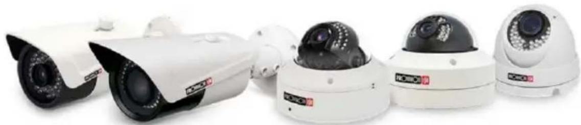
Row of white surveillance cameras with black and white modules, no visible text or labelsIP Series
CAMERA USER MANUAL
This user manual covers the following cameras:
Eye-Sight:
• 390IP5 2MP Series
• 340IP5+ 4MP Series
• 250IP5 5MP Series
• 280IP5 8MP Series
Dark-sight
• 251IP5+ 5MP Series
VF/MVF Lens Models (Excluding DI-VF Models)
v4.2 User Manual
For H.265 IP Camera
All rights reserved
Notes
■ Before operating the camera, we strongly advise users to read this manual and keep it for later use.
■ Please use the specified power supply to connect.
■ Avoid incorrect operation, shock vibration, heavy pressing which can cause damage to the product.
■ Do not use corrosive detergent to clean the body of the camera. If necessary, please use a soft dry cloth to wipe dirt; for hard contamination, use neutral detergent. Any cleanser for high-grade furniture is applicable.
■ Avoid aiming the camera directly towards extremely bright objects, such as the sun, as this may damage the image sensor.
■ Please follow the instructions to install the camera. Do not reverse the camera, or the reversing image will be received.
■ Do not operate the camera in extreme temperatures or extreme humidity conditions.
■ Use the power supply supplied authorized by a PROVISION-ISR technician.
- Keep away from heat sources such as radiators, heat registers, stove, etc.
The instructions in this manual could be outdated; if you need any clarifications you can contact an authorized PROVISION-ISR technician. PROVISION-ISR reserves the right to add changes to this manual and publish it online on our website (www.provision-ISR.com): there may be inconsistencies with the latest version. This applies to any and all software upgrades and product improvements, interpretation and modification added. These changes will be published in the latest version without prior notification.
■ When this product is in use, the relevant contents of Microsoft, Apple and Google will be involved in. The pictures and screenshots in this manual are only used to explain the usage of our product. The ownership of trademarks, logos and other intellectual properties related to Microsoft, Apple and Google belong to the above-mentioned companies.
■ All pictures and examples used in the manual are for reference only.
Table of Contents
1 Introduction....1
2 IE Remote Access....2
2.1 LAN....2
2.1.1 Access through IP-Manager....2
2.1.2 Direct Access through IE....4
2.2 WAN 5
3 Live Preview 6
3.1 The Live Preview Interface....6
3.2 MVF (Motorized Vari-Focal) Controls*....7
3.3 RS-485 (PTZ) Controls 8
4 IPC Configuration 8
4.1 System Configuration 8
4.1.1 Basic Information....8
4.1.2 Date & Time Configuration 10
4.1.3 Local Config 10
4.1.4 Storage 11
4.2 Video Configuration 13
4.2.1 Camera Configuration.... 14
4.2.2 Video/Audio....15
4.2.3 OSD Configuration 16
4.2.4 Video Mask....17
4.2.5 ROI Configuration 18
4.2.6 Zoom/Focus* 18
4.3 PTZ Configuration....19
4.3.1 Protocol....19
4.4 Alarm Configuration....20
4.4.1 Motion Detection 20
4.4.2 General Fault....21
4.4.3 Alarm In 24
4.4.4 Alarm Out....25
4.5 Basic Analytics 27
4.5.1 Object Monitoring....27
4.5.2 Camera Tampering 29
4.5.3 Line Crossing 30
4.5.4 Sterile Area 32
4.5.5 Crowd Density....34
4.5.6 People Intrusion....36
4.5.7 People Counting....37
4.5.8 Analytics and Live Display....40
4.6 Network Configuration....40
4.6.1 TCP/IP 40
4.6.2 Port 41
IP CAMERA USER MANUAL
4.6.3 Server Configuration 42
4.6.4 DDNS Configuration 42
4.6.5 SNMP 44
4.6.6 802.1X 44
4.6.7 RTSP....44
4.6.8 UPnP 45
4.6.9 Email Setting....46
4.6.10 FTP 47
4.6.11 QoS....48
4.7 Security 48
4.7.1 User 48
4.7.2 Online Users....49
4.7.3 Block and Allow Lists....50
4.8 Maintenance....51
4.8.1 Configure Backup & Restore 51
4.8.2 Reboot Device 52
4.8.3 Upgrade....53
4.9 Playback 53
5 Mobile Surveillance ....56
5.1 Network Configuration....56
6 Q & A....57
1 Introduction
This IPC (short for IP Camera) is designed for high-performance CCTV solutions. It adopts the state of the art video processing chips and utilizes most advanced technologies, such as video encoding and decoding technology, complies with the TCP/IP protocol, SoC, etc to ensure that this system will be extremely stable and reliable. The IPC device should be used together with Provision-ISR's IP manager to enable the quick setting and full utilization of the camera.
Main Features
- ICR auto switch, true day/night
● H.265/H.264 Compression - 3D DNR,
- True WDR*/BLC/HLC
- ROI coding
● Support CVBS output
● Support MIC in/out
● Support Alarm in/out
● Support RS485 Output - PoE power supply
- Remote monitoring support (Via smartphone/CMS/IE)
2 IE Remote Access
You may connect IPC via LAN or WAN. In this manual, we will use IE v11 for example. The details are as follows:
2.1 LAN
In LAN, there are two ways to access IPC:
- Access through IP Manager Software.
- Direct access through IE browser.
2.1.1 Access through IP-Manager
① Make sure the PC and IPC are connected to the LAN and that the IP-Manager is installed on the PC. You can install the IP manager form the disc provided with the camera or download it by clicking here.
② Double-click the IP-Manager icon on the desktop to run this software as shown below:
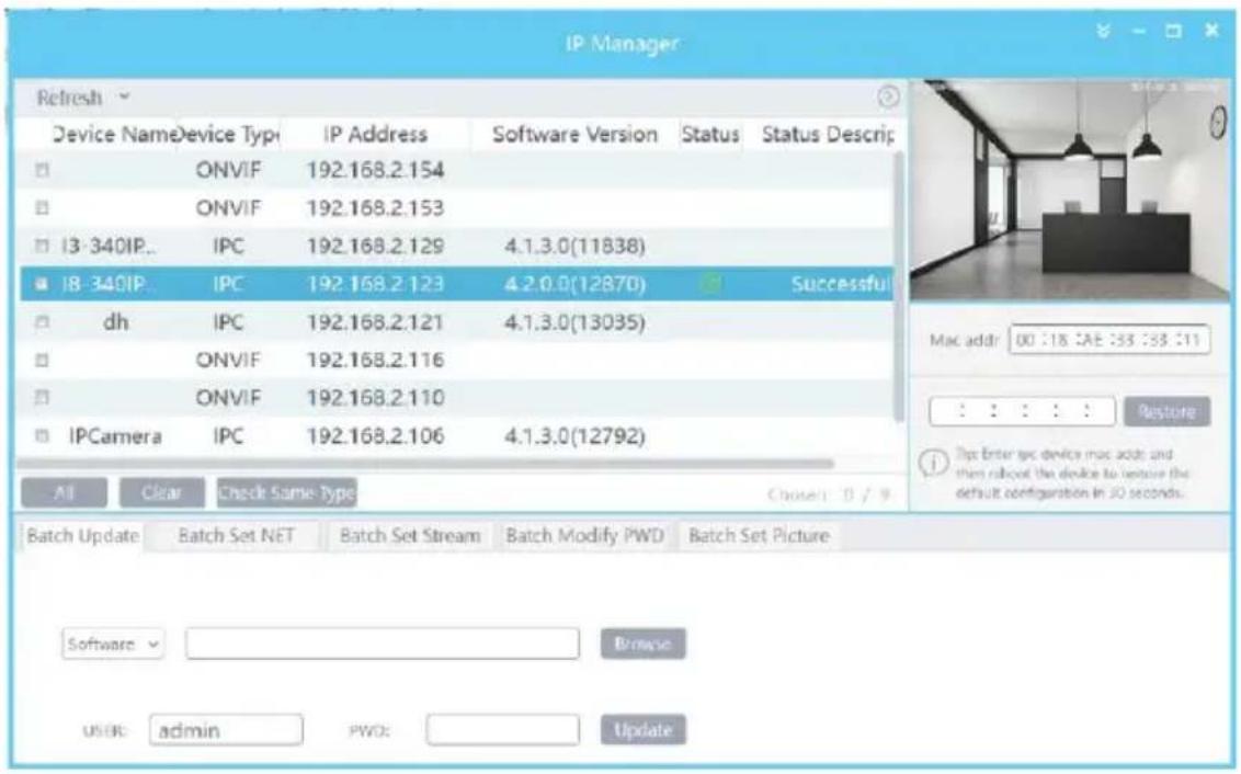
③ Modify the IP address. The default IP address of this camera is 192.168.226.201. Tick all the cameras you wish to set and then click on the “Batch Set NET” tab.
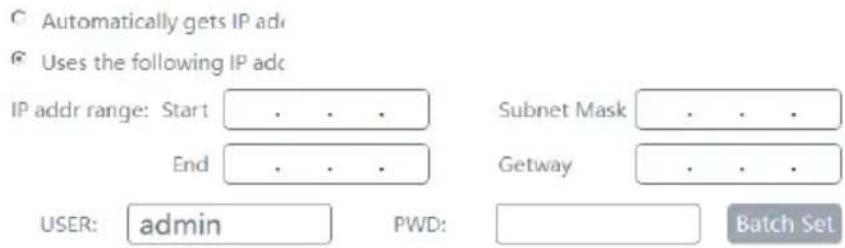
If you wish to use DHCP (IP Address automatic assignment), choose “Automatically gets IP address”, set the password and click on “Batch set”. Wait for a few moments until the IP manager will configure the cameras. After configuration, the IP addresses of the cameras will refresh automatically.
Please note:
1) In order for the DHCP mode to work, you must have a DHCP server on the LAN.
2) Using DHCP for permanent installations is not advisable as the IP Address might change after a while and cause the camera to be unreachable.
If you wish to set static IP addresses, choose “Uses the following IP Addresses”, set the range of IP addresses you wish to assign (First and last address), set the gateway and subnet mask and click on batch set. Wait for a few moments until the IP manager will configure the cameras. After configuration, the IP addresses of the cameras will refresh automatically.
Please note:
1) The IP range must fit the number of chosen cameras.
2) The selected IP addresses in the specified range must be available.
For example, if the IP address of your computer is 192.168.1.4, then the IP address of the cameras should be changed to 192.168.1.x. (x stands for any number between 1 and 255).

The default password of the administrator is "123456".
④ Double click on the IP address of the system will pop up IE browser and connect to the IPC. IE browser will auto download the Active X control. You must install it in order for the camera to work. After successful installation, a login window will appear as shown below.
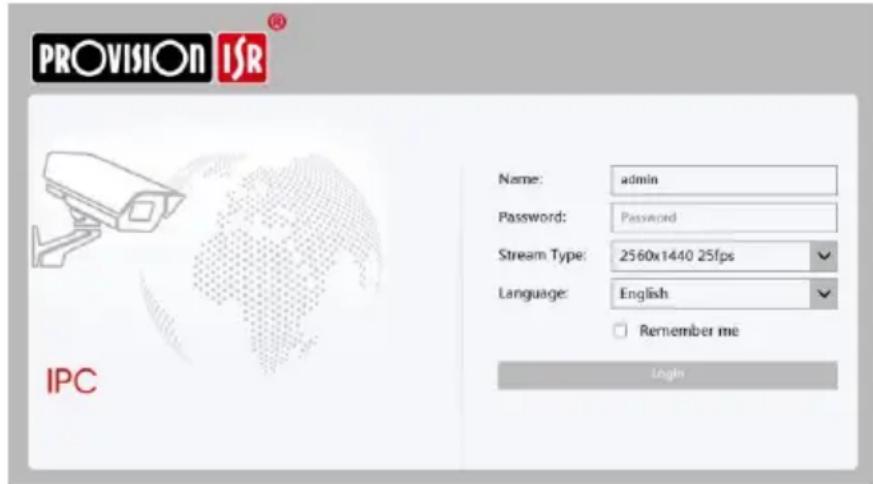
Input the username and password to log in.

The default username is “admin”; the default password is “123456”.
2.1.2 Direct Access through IE
The default network settings are as shown below:
IP address: 192.168.226.201
Subnet Mask: 255.255.255.0
Gateway: 192.168.226.1
HTTP: 80
Data port: 9008
You may use the above default settings when you log in the camera for the first time.
① You can use the IP manager to access the camera even if the camera is still using the default IP address. Double click on the IP address within the IP manager for the system to pop up IE browser and connect to the IPC. IE browser will auto download the Active X control. You must install it in order for the camera to work. After successful installation, a login window will appear.
You can then set the IP address from the camera configuration menu.
② If you wish to access the camera using its default IP address you will have to manually set the IP address of the PC to be in the same IP segment as the default settings of the IP camera. Open the network and sharing center. Click “Local Area Connection” to pop up the following window.
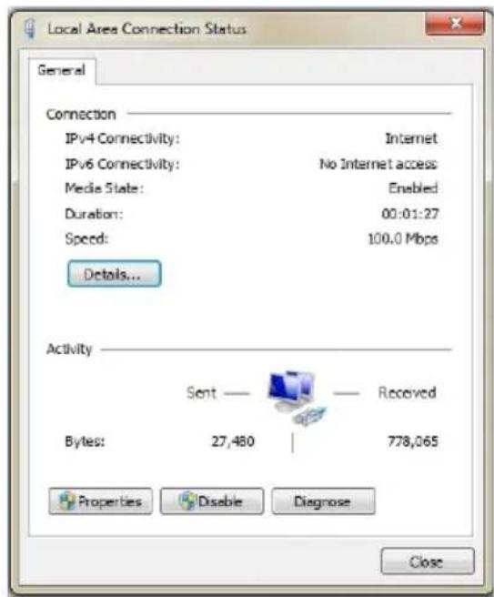
Select “Properties” and then select internet protocol according to the actual situation (most probably you are using IPv4). Next, click “Properties” button and set the network of the PC as shown below.
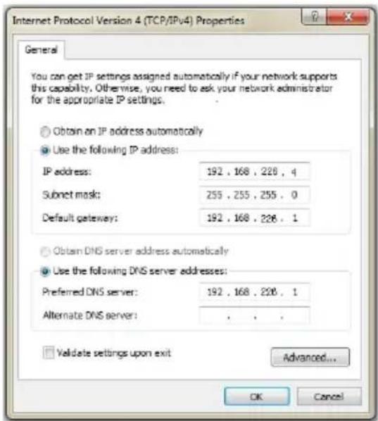
② Open the IE browser and input the default address of IPC and confirm. The IE browser will download Active X control automatically.
③ After downloading and installing the Active X control, the login dialog box will appear.
④ Input the default username and password and click "Login".
2.2 WAN
Allows you to access the camera using a router or virtual server.
① Make sure the camera is well connected and configured via LAN. Log in the camera via LAN and go to the Config→Network Config→Port menu to set up the port number.
② Go to Config → Network Config → TCP/IP menu to modify the IP address.
③ After modifying the IP Address, click on “Port” and modify the port according to your needs.
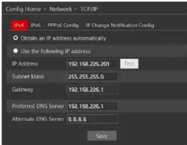
Port Setup
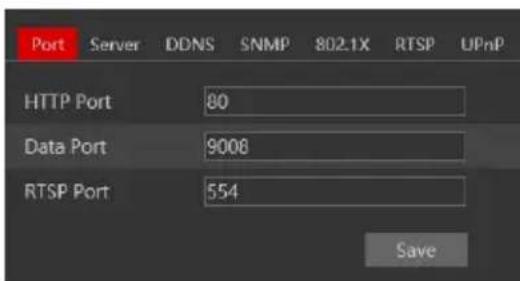
IP Setup
④ Go to the router's management interface through IE browser to forward the IP address and port of the camera to the “Virtual Server”. In the picture example below you will see an example of the setting as if the IPC IP address is “192.168.6.6” and the ports are default (9008 & 80)
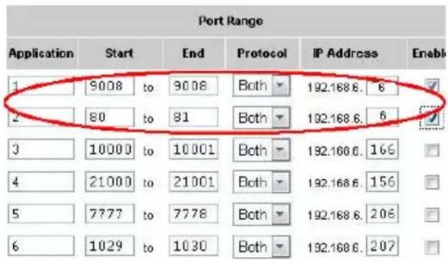
Router Setup
④ Open the IE browser and input your WAN IP and HTTP port to access the camera.
3 Live Preview
3.1 The Live Preview Interface
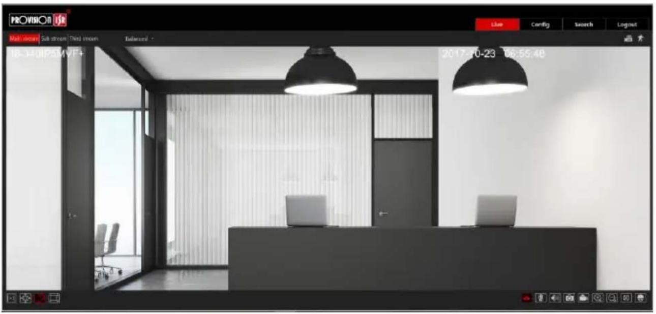
Icons and operation buttons:
| Icon | Description | Icon | Description |
 | Actual Size |  | Digital Zoom-Out |
 | Fit to screen - True Proportions |  | MVF Controls* |
 | Fit to screen - Stretch |  | PTZ Controls (Through RS-485 output) |
 | Full screen |  | Motion Detection indicator |
 | Enable/Disable live view |  | SD Card recording indicator |
 | Talk |  | Alarm In Indicator |
 | Listen |  | Use mainstream for live-view |
 | Take Snapshot |  | Use sub-stream for live-view |
 | Enable/Disable Local Recording |  | Use third stream for live-view |
 | Digital Zoom-in |  | Choose the buffering plan |
3.2 MVF (Motorized Vari-Focal) Controls\*
Clicking on the MVF lens controls will unfold the MVF control panel. Using this interface, you can control the zoom and focus of the MVF lens.
The descriptions of the control panel are as follows:
| Icon | Description | Icon | Description |
 | Zoom Out |  | Focus In |
 | Zoom In |  | One Key Focus |
 | Focus Out |
*Relevant for MVF Models Only
3.3 RS-485 (PTZ) Controls
Clicking on the PTZ extended button to unfold PTZ control panel. Using this interface will control the RS-485 Output of the camera.
Please note: RS-485 output must be properly configured before being able to control any device.
The descriptions of the control panel are as follows:
| Button | Description |
 | to rotate the dome upwards; to rotate the dome downwards; to rotagethe dome towards left; to rotate the dome towards right; to rotate the domediagonally up-left; to rotate the dome diagonally up-right; to rotate the domediagonally down-left; to rotate the dome diagonally down-right; to stoprotating the dome. |
 | Drag the scroll bar to adjust the rotating speed of the dome. |
 | Zoom button. Click to zoom in the image; click to zoom out the image. |
 | Focus button. Click for far focus; Click for near focus. |
 | Iris button. Click reduce the iris size; click to increase the iris size. |
4 IPC Configuration
In this chapter, we will go through all the possible configurations of the IPC.
4.1 System Configuration
The “System Configuration” includes four submenus: Basic Information, Date & Time, Local Config and Storage.
4.1.1 Basic Information
In the “Basic Information” interface, you can view all the necessary information related to the IPC, as seen below:
| Config Home ▶ System ▶ Basic Information | |
| Device Name | 18-340IP5MVF+ |
| Product Model | 18-340IP5MVF+ |
| Brand | Provision ISR |
| Software Version | 4.2.0.0(12870) |
| Software Build Date | 2017-08-22 |
| Kernel Version | 20170413 |
| Hardware Version | 1.3-1414405 |
| Onvif Version | 16.12(#2) |
| OCX Version | 2.0.1.3 |
| MAC | 00:18:ae:33:33:11 |
The following table will explain the available detail field.
| Parameter | Meaning |
| Device name | Name of the device – can be modified from the OSD settings |
| Product Model | The model of the device |
| Brand | The brand of the camera |
| Software version | The current software version |
| Software build date | The software build-date |
| Kernel version | The kernel version of the device |
| Hardware version | The hardware version of the device |
| ONVIF Version | The current ONVIF version |
| OCX Version | The current OCX version |
| Mac Address | The MAC address of device |
4.1.2 Date & Time Configuration
Setting steps:
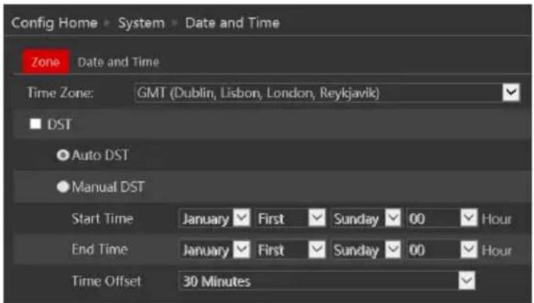
- Go to Config→Date & Time menu as shown below.
-
Set the time zone.
-
Enable DST mode if required. DST settings are already configured according to your time zone. If you wish to set the DST manually, switch to “Manual DST” and set it accordingly.
- To set the date and time, click on the “Date and Time” tab. You may synchronize the camera time with an NTP server (Internet connection required), synchronize the camera time with the time of the computer you are using or set the time manually.
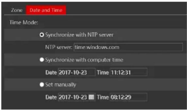
4.1.3 Local Config
- Got to "System Configuration" "Local config" as shown below:
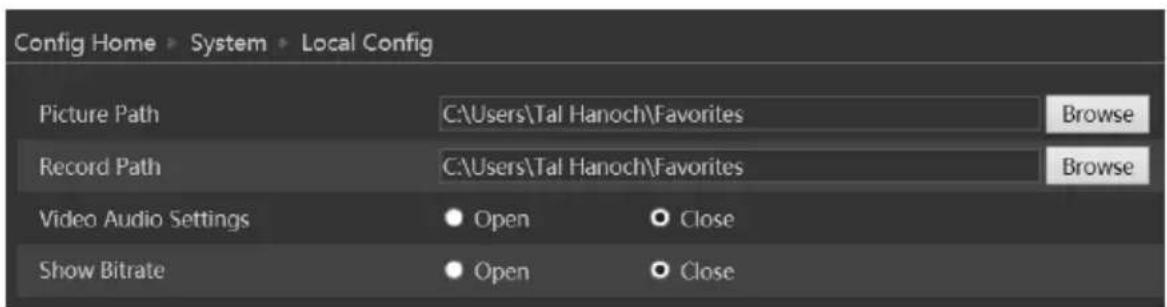
From here you can set the path on your computer where local snapshots and videos will be saved.
You can also choose if the camera will show the current bit-rate on the live-view image (Local interface only).
4.1.4 Storage
The SD card feature allows you to insert an SD card into the camera and enable the camera to operate with a local storage. The SD card will be used for both snapshot and video files. You can allocate a certain percentage for each from the settings menu.
- Go to "System Configuration" "Storage" as shown below:
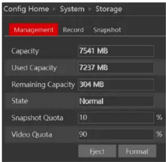
If it is the first time you are using the SD card with the camera or if the state is showing any value different than “Normal”, you should click on “Format” before the SD card will be available for recording.
Click “Eject card” to stop writing data to SD card and allow you to remove it safely. Inserting an SD card to the camera must be done while the camera is powered off.

Note: Using of SD card function should be coordinated with motion or sensor alarms.
The following table will explain the available detail field.
| Parameter | Meaning |
| Capacity | The total capacity of the SD card |
| Used capacity | The capacity currently being used |
| Remaining Capacity | The available capacity |
| State | The state of the SD card. |
| Snapshot Quota | The percentage of the SD card dedicated for Snapshots |
| Video Quota | The percentage of the SD card dedicated to Videos |
The next tab is "Record". Click on it to set the video recording parameters and schedule.
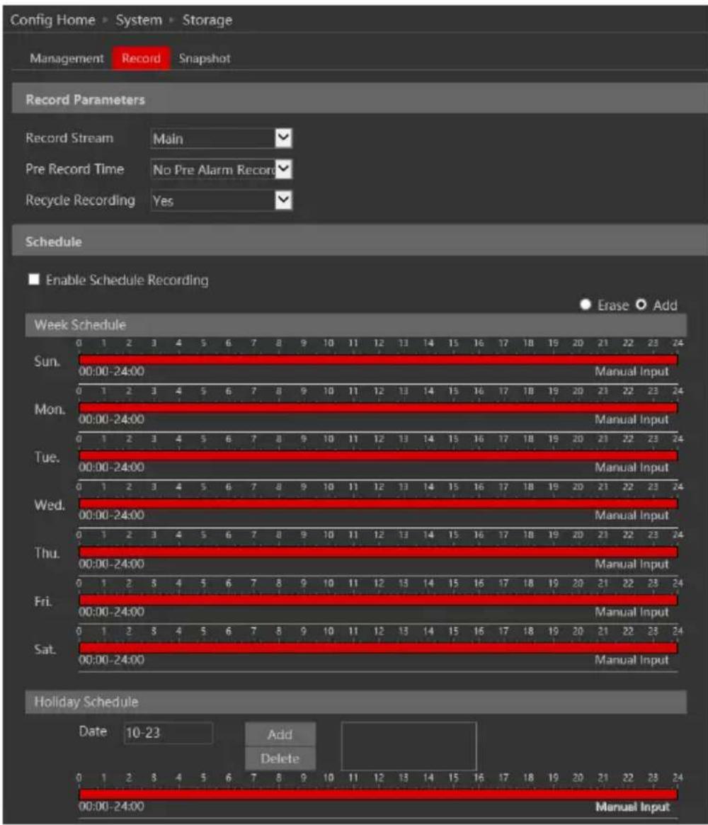
The video parameters are as follows:
| Parameter | Meaning |
| Record stream | Which video stream will be used for record |
| Pre-recording time | The duration of video prior to the recording trigger |
| Cycle recording | Weather to recycle record or stop when the SD card is full |
Below are the schedule settings. Enable the schedule if required and set the recording time for each of the weekdays. You can also set a holiday schedule and add required dates to it.
The next tab is "Snapshot" Click on it to set the snapshot parameters and schedule.
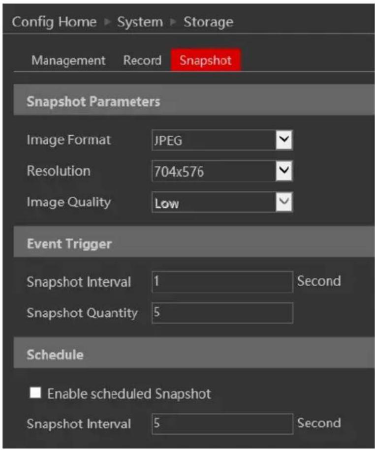
The snapshot parameters are as follows:
| Parameter | Meaning |
| Image Format | The image format is JPEG |
| Resolution | Set the snapshot resolution |
| Image quality | The quality of the image reflects on its size. |
| Snapshot Interval | The duration between two snapshots |
| Snapshot Quantity | The total number of snapshots to be taken after a trigger |
| Scheduled snapshots | Taking a snapshot according to a specified schedule |
Below are the schedule settings. Enable the schedule if required and set the recording time for each of the weekdays. You can also set a holiday schedule and add required dates to it.
4.2 Video Configuration
Camera Configuration includes five submenus: Display Configuration, Video Stream, OSD Config, Video Mask and ROI Config.
4.2.1 Camera Configuration
Setting steps:
- Go to "Video Configuration" → "Display" interface as shown below.
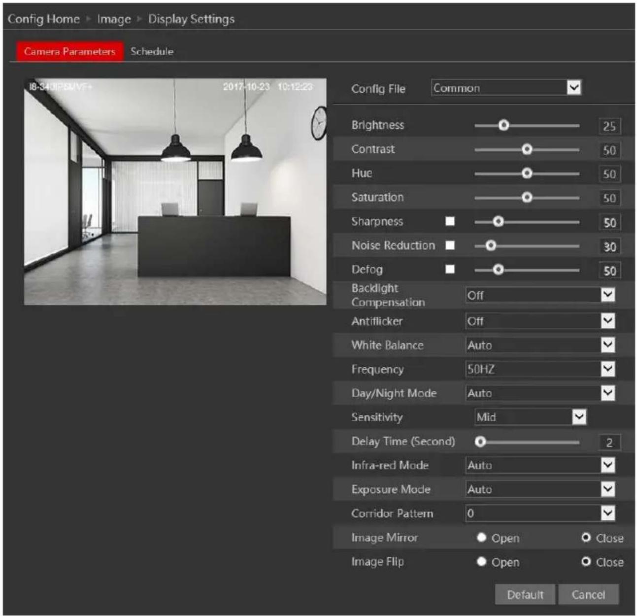
The display parameters are as follows:
| Parameter | Meaning |
| Config file* | You can set an individual configuration for Day and night. Common is used for both |
| Brightness | Set the image brightness |
| Contrast | Set the image contrast |
| Hue | Set the image hue |
| Saturation | Set the image saturation |
| Sharpness | Enable/Disable the sharpness and set its level |
| Noise reduction | Enable/Disable the 3D-DNR and set its level |
| Defog | Enable/Disable the defog and set its level |
| Backlight | Set HLC/BLC/True-WDR to deal with advanced light conditions. |
| Anti-Flickering | Manually set the shutter to synchronize with 50/60Hz environments. |
| White Balance | Set the white balance of the camera |
| Frequency | Set the frequency to 50/60Hz |
| Day/Night Mode* | Set the day/night mode (Auto/Day/Night/Schedule) |
| - Sensitivity | The light sensor sensitivity |
| - Delay Time | The delay time before switching day/night modes |
| Infra-Red Mode | Set the IR status |
| Exposure Mode | Set the exposure to auto or set it manually |
| Corridor Pattern | Rotate the image to fit corridors |
| Image Mirror | Mirror the image horizontally |
| Image Flip | Flip the image vertically |
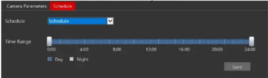
*If you set the day/night mode to schedule or you wish to differentiate between the daytime and night-time image settings, you will need to set the schedule accordingly.
Click on the "Schedule" tab and set the schedule as you wish.
4.2.2 Video/Audio
Go to “Video configuration” → “Video/Audio” to see an interface as shown below.
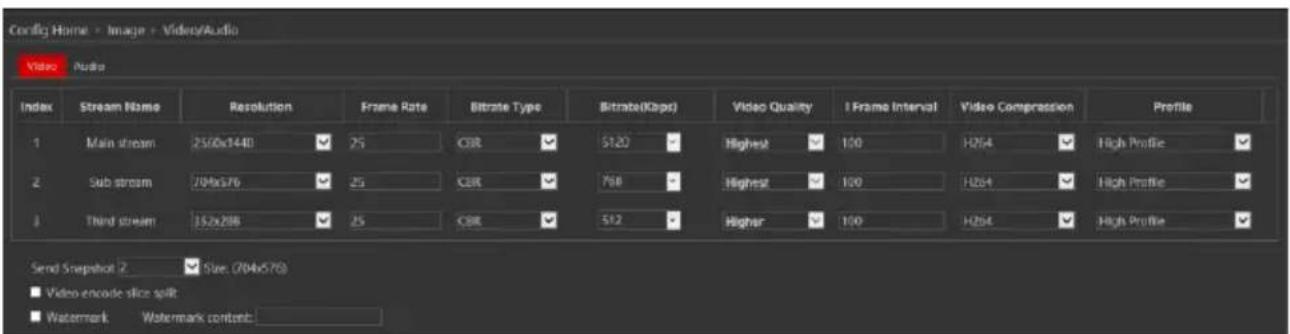
Three video streams are available. You can set each one of them differently with the limitations of the camera's capabilities.
Resolution: The higher the resolution is, the bigger the image is.
Frame rate: The higher the frame rate is, the more fluent the video is. However, more storage room will be taken up.
Bitrate type: CBR and VBR are available. CBR (Constant Bit-Rate) means that no matter how what the video resources are, the compression bitrate will be constant as configured. This will not only facilitate the image quality better in a constant bitrate but also help to calculate the capacity of the recording. VBR (Variable Bit-Rate) means that the compression bitrate can be automatically adjusted according to the change of the video resources with the configured bit-rate as the maximum value. This will help to optimize the storage network bandwidth.
Video Quality: When VBR is selected, you need to choose image quality. The higher the image quality you choose, the more bitrate will be required.
Bitrate: Please set it according to your needs while taking in consideration the bandwidth and storage limits.
I Frame interval: It is recommended to use the default value. If the value is too high, the read speed picture group will be slow resulting in video quality loss.
Video Compression: Choose between H.265 and H.264. The IPC also support MJPEG on sub-stream resolution but you need to make sure that the application connected to the camera also supports it.
Profile: Baseline, main profile and high profile are optional. Baseline profile is mainly used in interactive applications with low complexity and delay. The main or high profile is mainly used for higher coding requirements.
Send Snapshot: Please select it according to the actual situation.
Video encode slice split: If enabled, you may get a more fluent image even when using a low-performance PC.
Watermark: You can set a watermark that will appear on the image.
In the next tab we have "Audio" settings as shown below:
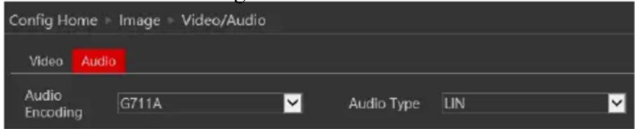
Set the encoding profile as desired and the type of audio input. If LIN (Line) is selected, it means that the audio input is already amplified and the input volume will be set to "low". If MIC (Microphone) will be selected, it means that the audio signal is not amplified and the input volume will be set to "high".
4.2.3 OSD Configuration
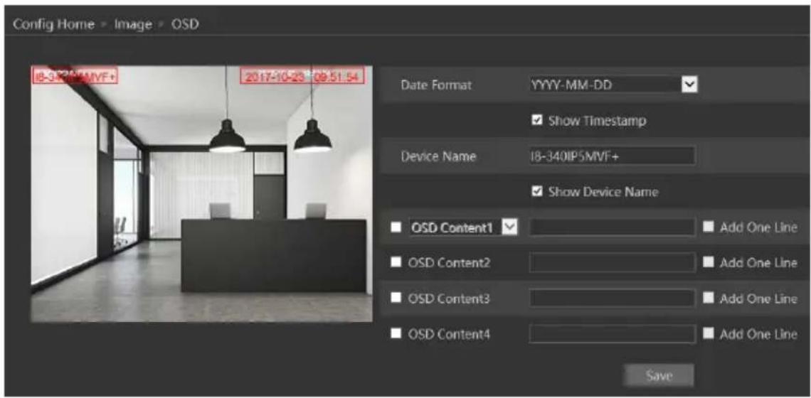
Go to “Video Config” → “OSD” menu to display the interface as shown below.
You may set the device name, time stamp and custom OSDs here. Drag the time stamp and custom OSD over the image on the left side to set their position. Then press the “Save” button to save the settings.
4.2.4 Video Mask
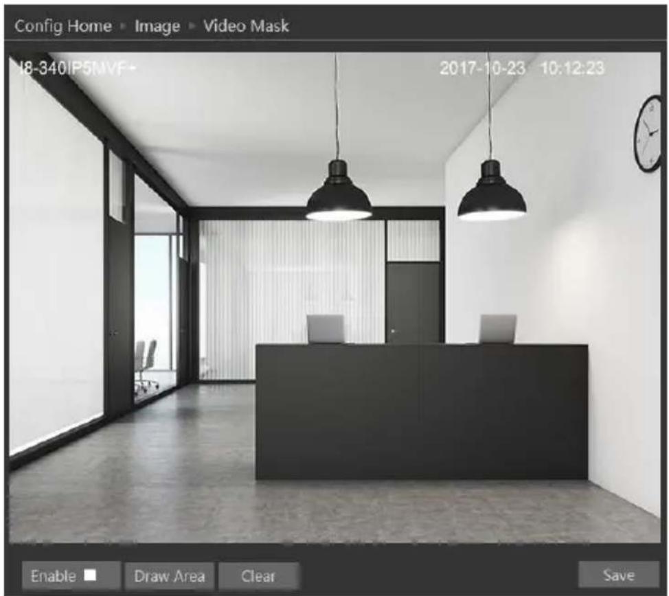
You can set 4 mask areas at most.
To set up video mask
- Enable video mask.
- Click "Draw" button and then drag the mouse to draw the video mask area.
- Click "Save" button to save the settings.
- Return to the live to see the following picture.
To clear the video mask:
Go to video mask menu and then click "Clear" button to delete the current video mask area.
4.2.5 ROI Configuration
ROI is used to allocate higher bit-rate on a certain area of the image than other areas To set up ROI
- Go to Config→ROI menu.
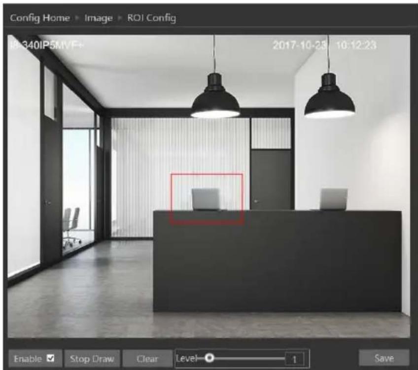
- Check "Enable" and then click "Draw" button.
- Drag the mouse to set the ROI area.
- Set the level.
- Click "Save" button to save the settings.
Now, you will see that the selected ROI area is clearer than other areas, especially in low bit-rate settings.
4.2.6 Zoom/Focus\*
The zoom/focus interface is used for setting the lens of the camera (In MVF Models only).
You can also enable “Day/Night Switching focus” which will refocus the lens every time the camera switched from day to night and vice-versa.
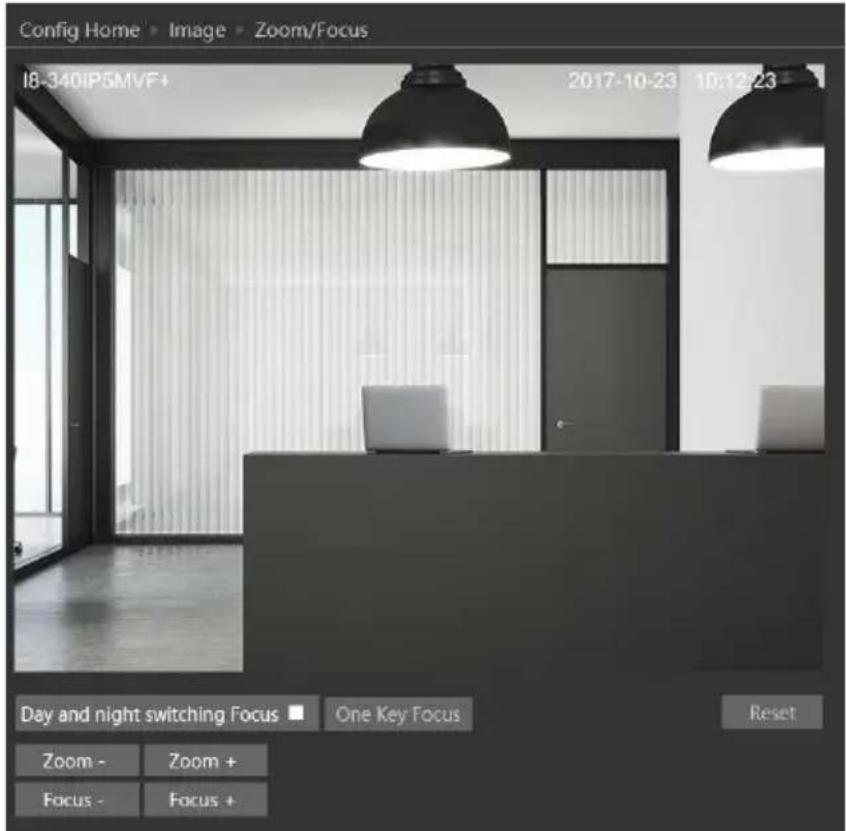
"One Key Focus" will automatically focus the lens in one click.
Zoom +/- will manually control the zoom ratio.
Focus +/- will manually set the focus of the lens.
4.3 PTZ Configuration
PTZ Configuration relates to the RS-485 output of the camera and includes three settings: Protocol, address, and baud-rate.
4.3.1 Protocol
- Go to "PTZ Configuration"→ "Protocol" interface as shown below:
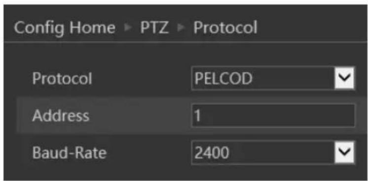
- Input the protocol, address and baud rate according to the speed dome.
4.4 Alarm Configuration
Alarm configuration includes four submenus: Motion Detection, General Fault, Alarm in and Alarm Out.
4.4.1 Motion Detection
Go to “Alarm configuration”→“Motion Detection” to see an interface as below.
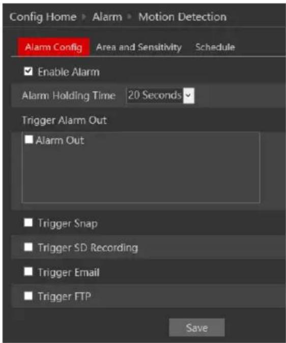
The first tab is the “Alarm Config”. Enable or disable the alarm and set the alarm holding time. The holding time means that the alarm signal will stay active and no additional alarms will be generated during that time.
Choose the camera's response to the alarm:
| Alarm Triggers: | |
| Alarm Out | triggers the alarm out relay |
| Trigger Snap | takes a snapshot (SD card must be available) |
| Trigger SD Recording | Initiates video recording over the SD card (SD card must be available) |
| Trigger Email | sends an email as configured in the Email section. |
| Trigger FTP | send a snapshot as configured in the FTP section |
Next is the “Area and Sensitivity” Tab. Move the “Sensitivity” scroll bar to set up the motion sensitivity and click on “draw” to enable the marking on the image. Note that you can set different sensitivities to a different area of the picture as shown below. Once finished, click on “Stop Draw”.
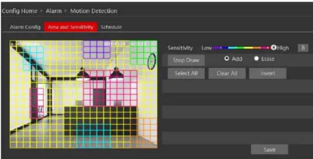
- Click "Save" to save the settings.
Last is the "Schedule" tab:
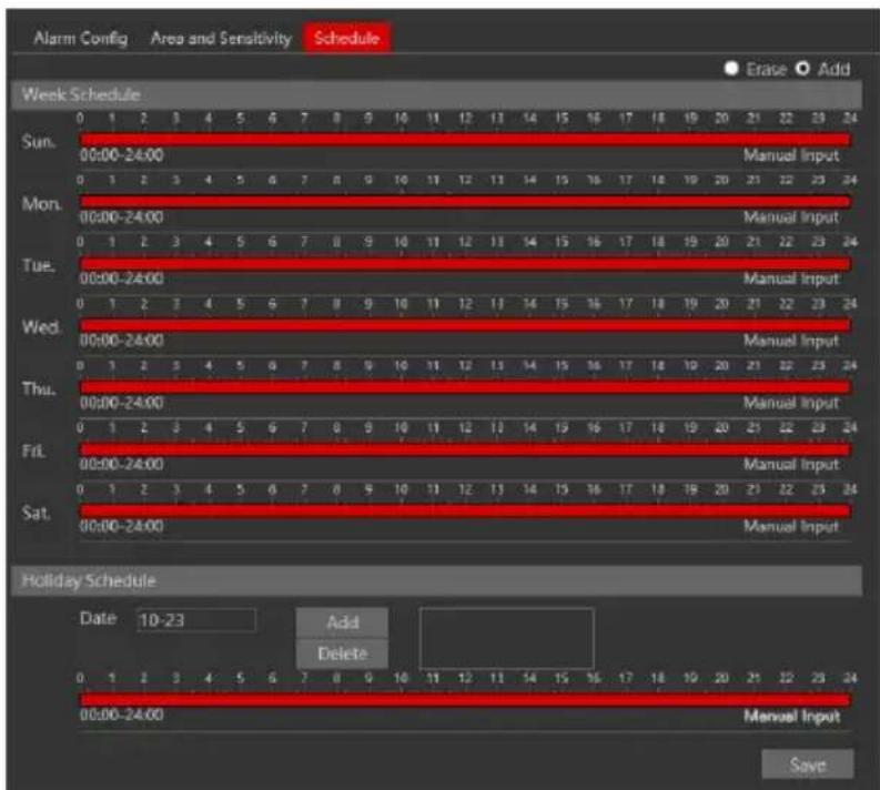
Set the active alarm time for each of the weekdays. You can also set a holiday schedule and add required dates to it.
4.4.2 General Fault
A problem with the network cable or with the SD card will produce a general fault. The alarms can be configured as follows: SD Card Full, SD Card Error, IP Address Conflict, Network cable disconnected.
Enter “Alarm Configuration”→ “General Faults” to see a screen as shown below. The default tab is “SD Card Full”:
Enable the alarm if required. This alarm will only be relevant if “Recycle Record” is not marked. If “recycle record” is active, the SD card will never get full.
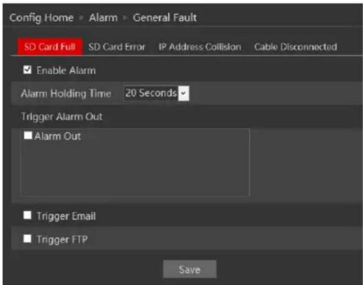
After enabling the alarm, choose the responses required from the camera in case the alarm will be active. After the setting is complete, click “Save”.
Next is the “SD Card Error” Tab. This alarm will be triggered if any fault will be developed with the SD card. It can be a malfunction or removing the SD card from the camera.
To activate it, enable the alarm.
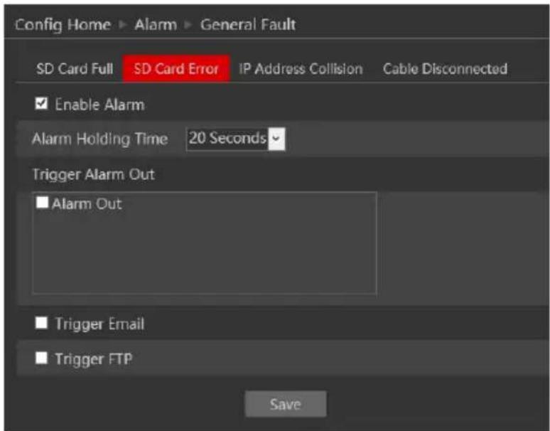
After enabling the alarm, choose the responses required from the camera in case the alarm will be active. After the setting is complete, click “Save”.
Next is the “IP Address Collision”. This alarm will be triggered when another device in the network will be assigned with the same IP address of the IPC (or vice versa).
To activate it, enable the alarm.
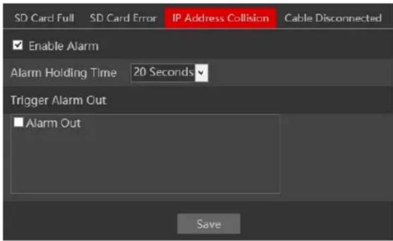
After enabling the alarm, choose the responses required from the camera in case the alarm will be active. Note that any response related to the network such as email or FTP is not available since in most cases the network will become unavailable for the camera. After the setting is complete, click “Save”.
Last is the “Cable Disconnected” tab. This alarm will be generated if the network cable will be disconnected from the camera. Please note that this alarm is not usable if you are using PoE to power the camera since the disconnection of the cable will cause the camera to turn off due to power loss.
To activate it, enable the alarm.
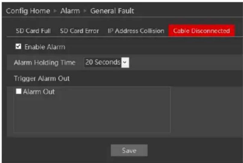
After enabling the alarm, choose the responses required from the camera in case the alarm will be active. Note that any response related to the network such as email or FTP is not
available since the disconnection of the network cable prevents any external network communication by the camera. After the setting is complete, click "Save".
4.4.3 Alarm In
Enter “Alarm”→“Alarm In” to see a screen as shown below:
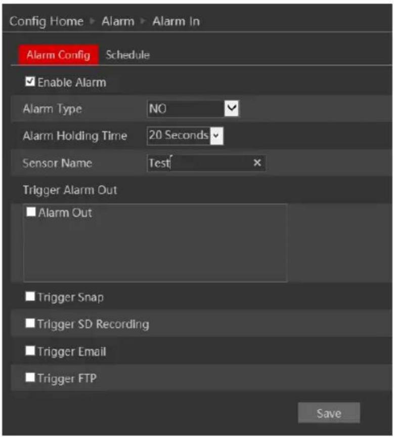
- Enable the alarm to activate it and see the configuration parameters:
| Parameter | Meaning |
| Alarm Type | You can set it to “NO” (Normally open) which means that the once the line is closed the alarm will be active, or “NC” (Normally Closed”) which means that once the line is open the alarm will be active. |
| Alarm Holding Time | The holding time means that the alarm signal will stay active and no additional alarms will be generated during that time. |
| Sensor Name | You can set a unique name for easy identification. |
| Alarm Triggers: | |
| Alarm Out | triggers the alarm out relay |
| Trigger Snap | takes a snapshot (SD card must be available) |
| Trigger Email | sends an email as configured in the Email section. |
| Trigger FTP | send a snapshot as configured in the FTP section |
| Alarm Triggers: | |
| Alarm Out | triggers the alarm out relay |
| Trigger Snap | takes a snapshot (SD card must be available) |
| Trigger Email | sends an email as configured in the Email section. |
| Trigger FTP | send a snapshot as configured in the FTP section |
-
After the setting is complete, click "Save".
-
Next, you will need to set the alarm schedule. Click on the "Schedule" tab to get the following interface:
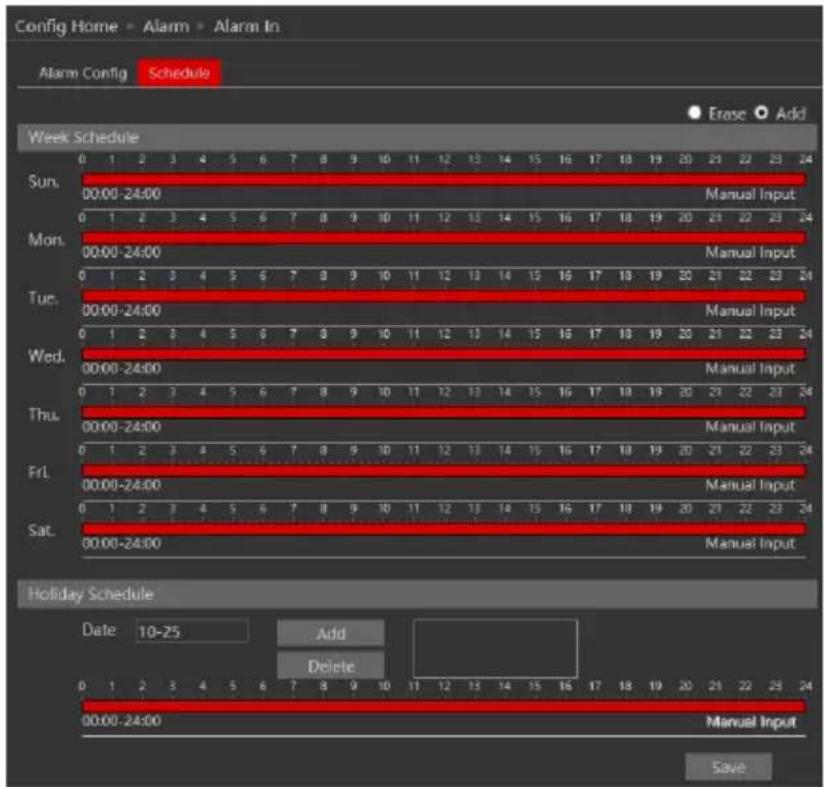
- Set the active alarm time for each of the weekdays. You can also set a holiday schedule and add required dates to it. The holiday schedule overtakes the normal schedule.
4.4.4 Alarm Out
The Alarm output is actually a relay that can operate many types of devices such as gates, doors, strobe light, and sirens. The alarm out always works in a “NO” mode (Normally open) which means that the relay is open in a normal state and closed in an armed state.
- Go to “Alarm”→“Alarm Out” to get to the interface as shown below:
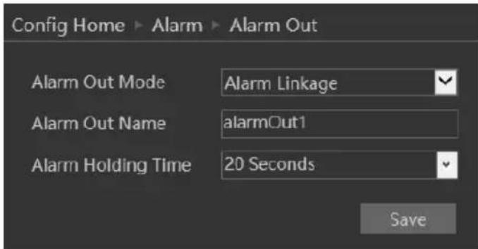
- Alarm out has 4 modes as described below:
A. Alarm Linkage (Shown Above): This mode will set the alarm out to be triggered as a response to any of the available alarms (Motion, Alarm in, Analytics). If this mode is chosen you will need to set it properly.
| Parameter | Meaning |
| Alarm Out Name | You can set a unique name for easy identification. |
| Alarm Holding Time | The holding time means that the alarm signal will stay active and no additional alarms will be generated during that time. |
B. Manual Mode: This mode will enable you to manually operate the relay.
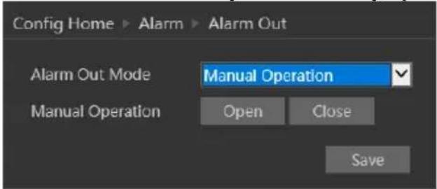
C. Day/night switch linkage: This mode allows you to set the relay condition according to the day/night mode of the camera.
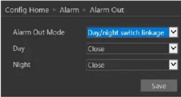
D. Schedule mode: This mode allows you to set the relay condition according to a pre-defined schedule.
Once chosen you will have to set the schedule. The set schedule will be relevant for all weekdays and cannot be set for each day independently.
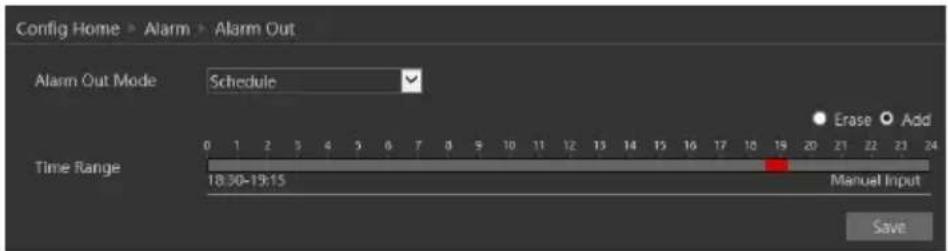
- Press the "Save" button to save the settings.
4.5 Basic Analytics
This version offers special video analytics that was designed to detect special scenarios and events. Video analytics detection is based on VMD (Video Motion Detection). v4.2 offers a variety of Analytics: Object Monitoring, Line Crossing, Sterile Area, Camera Tampering, Crowd Density, People Intrusion and People counting.
Note that some features might not be available in specific models. For confirmation please refer to the camera's technical specs.
4.5.1 Object Monitoring
Object Monitoring Analytics can work in one of two methods: Missing Item and Left Item. Missing item will detect if the marked item was moved or taken while left item will detect if an item was left behind in a defined area.
- Go to “Basic Analytics”→“Object Monitoring” to get to the interface as shown below:
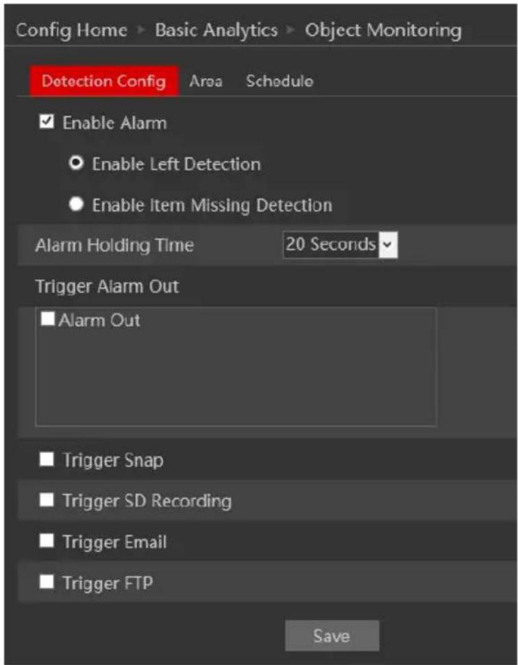
- Enable Alarm if required.
-
Choose if you wish for the object monitoring to work as "Missing Object" or "Left Object"
-
Set the Alarm response as follows and click "Save" to confirm:
| Alarm Triggers: | |
| Alarm Out | triggers the alarm out relay |
| Trigger Snap | takes a snapshot (SD card must be available) |
| Trigger SD Recording | Initiates video recording over the SD card (SD card must be available) |
| Trigger Email | sends an email as configured in the Email section. |
| Trigger FTP | send a snapshot as configured in the FTP section |
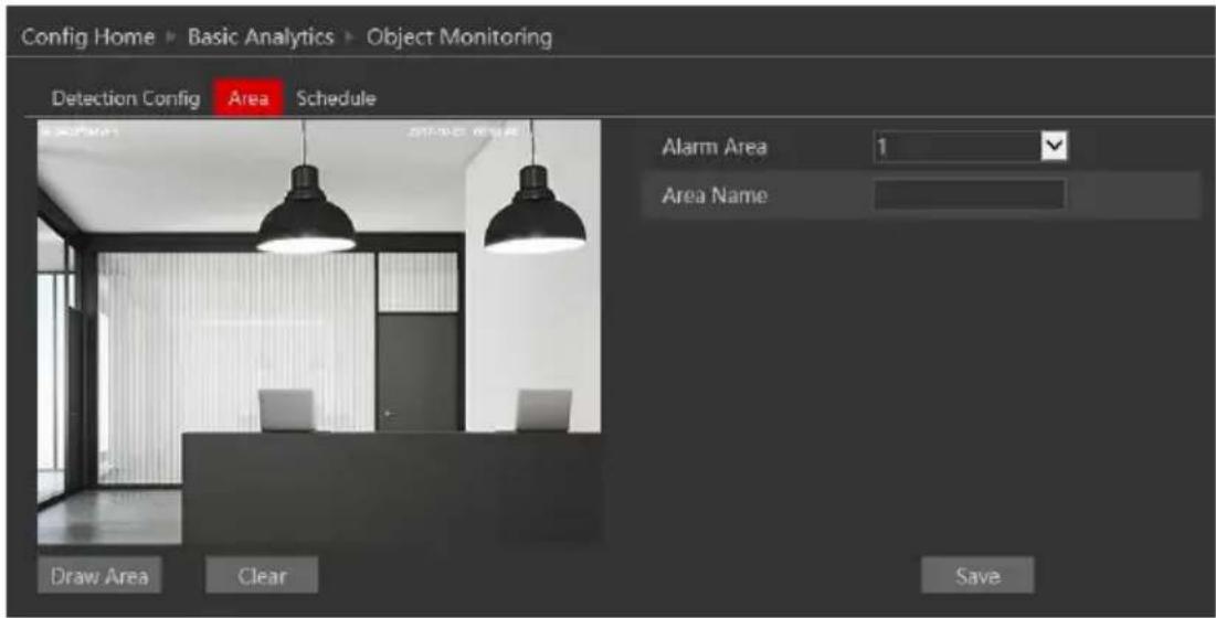
- Now you will have to set the detection area. Click on the "Area" tab to get to the interface shown below.
-
Click on "Draw Area".
-
If you set the detection to “Missing Object” you will have to draw the area around the object. Notice that the area should be large enough for the camera to see clearly and detect changes efficiently.
If you chose “Left object” you will need to draw an area for detection where left objects will trigger an alarm.
-
Set the area name.
-
Click "Save" to confirm the settings.
-
You can set up to 4 objects/areas. If you wish to set additional detection areas/objects, change the Alarm area number and repeat stages 6-9.
-
Next, you will need to set the schedule. Click on the “Schedule” tab to get the following interface:
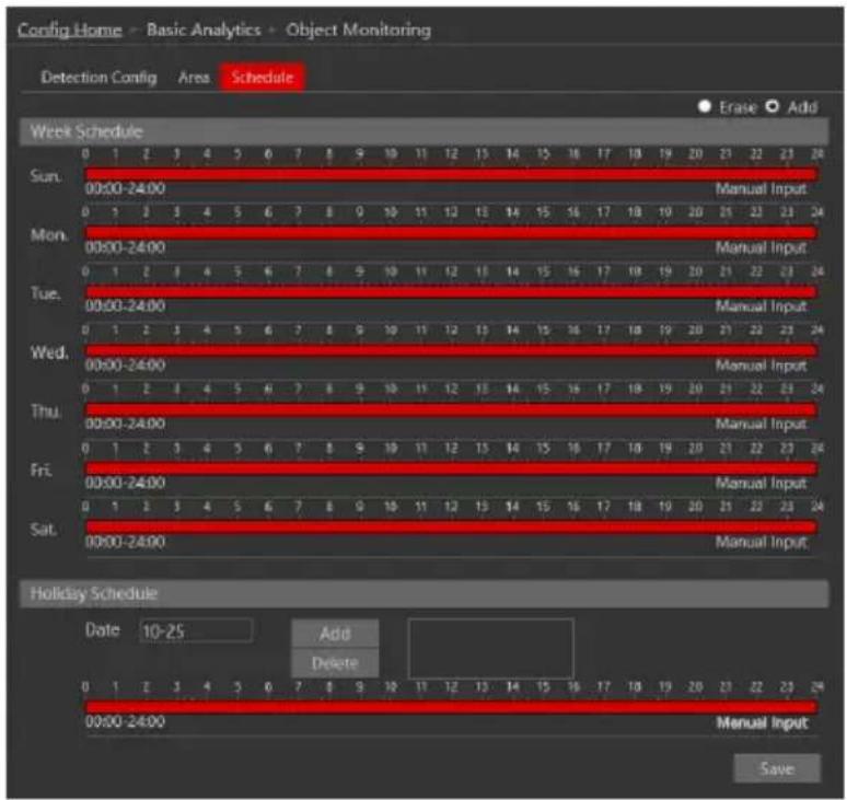
- Set the active alarm time for each of the weekdays. You can also set a holiday schedule and add required dates to it. The holiday schedule overtakes the normal schedule.
4.5.2 Camera Tampering
Camera tapering uses special analytics algorithm to detect if the camera was tampered with. This includes: Camera shifting – detects if the camera was shifted from its original location. Lens Tampering – detects if the lens was tampering resulting with a blurry image. Masking detection – detects if the camera view was covered or blocked by any means.
- Go to "Basic Analytics"→ "Camera Tampering" to get to the interface as shown below:
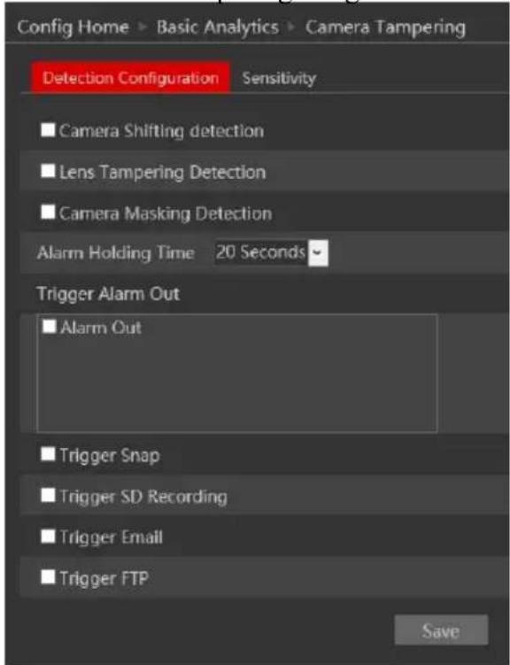
- Enable the required detection analytics out of Camera Shifting/Lens Tampering/Masking detection.
- Set the Alarm response as follows:
| Alarm Triggers: | |
| Alarm Out | triggers the alarm out relay |
| Trigger Snap | takes a snapshot (SD card must be available) |
| Trigger SD Recording | Initiates video recording over the SD card (SD card must be available) |
| Trigger Email | sends an email as configured in the Email section. |
| Trigger FTP | send a snapshot as configured in the FTP section |
-
Click "Save" to confirm.
-
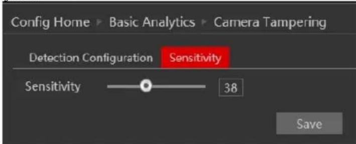
Go to the sensitivity tab:
-
Set the sensitivity (0 - lowest, 100 - Highest)
-
Click "Save" to confirm.
4.5.3 Line Crossing
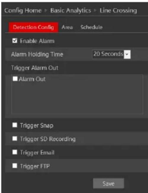
Line Crossing Analytics will detect if an object crossed a defined line. The crossing direction can be adjusted.
- Go to “Basic Analytics”→“Line Crossing” to get to the interface as shown below:
-
Enable Alarm if required.
-
Set the Alarm response as follows and click "Save" to confirm:
| Alarm Triggers: | |
| Alarm Out | triggers the alarm out relay |
| Trigger Snap | takes a snapshot (SD card must be available) |
| Trigger SD Recording | Initiates video recording over the SD card (SD card must be available) |
| Trigger Email | sends an email as configured in the Email section. |
| Trigger FTP | send a snapshot as configured in the FTP section |
- Now you will have to set the detection are (lines). Click on the "Area" tab to get to the interface shown below.

-
Click on "Draw Area".
-
Draw the line. The length of the line should be as long as possible to increase the detection efficiency.
-
Set the crossing direction. The “A” and “B” sides will reflect on the image on the left. The available options are. A→B – Crossing from A side to B side, B→A - Crossing from B side to A side, A<->B – Crossing from any side to any side.
-
Click "Save" to confirm the settings.
-
You can set up to 4 lines. If you wish to set additional lines, change the cordon number and repeat stages 6-9.
-
Next, you will need to set the schedule. Click on the "Schedule" tab to get the following interface:
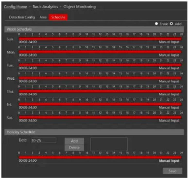
- Set the active alarm time for each of the weekdays. You can also set a holiday schedule and add required dates to it. The holiday schedule overtakes the normal schedule.
4.5.4 Sterile Area
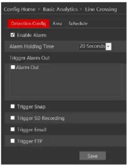
Sterile Area Analytics will detect if any object entered the defined area.
- Go to "Basic Analytics"→ "Sterile Area" to get to the interface as shown below:
-
Enable Alarm if required.
-
Set the Alarm response as follows and click "Save" to confirm:
| Alarm Triggers: | |
| Alarm Out | triggers the alarm out relay |
| Trigger Snap | takes a snapshot (SD card must be available) |
| Trigger SD Recording | Initiates video recording over the SD card (SD card must be available) |
| Trigger Email | sends an email as configured in the Email section. |
| Trigger FTP | send a snapshot as configured in the FTP section |
- Now you will have to set the detection area. Click on the "Area" tab to get to the interface shown below.
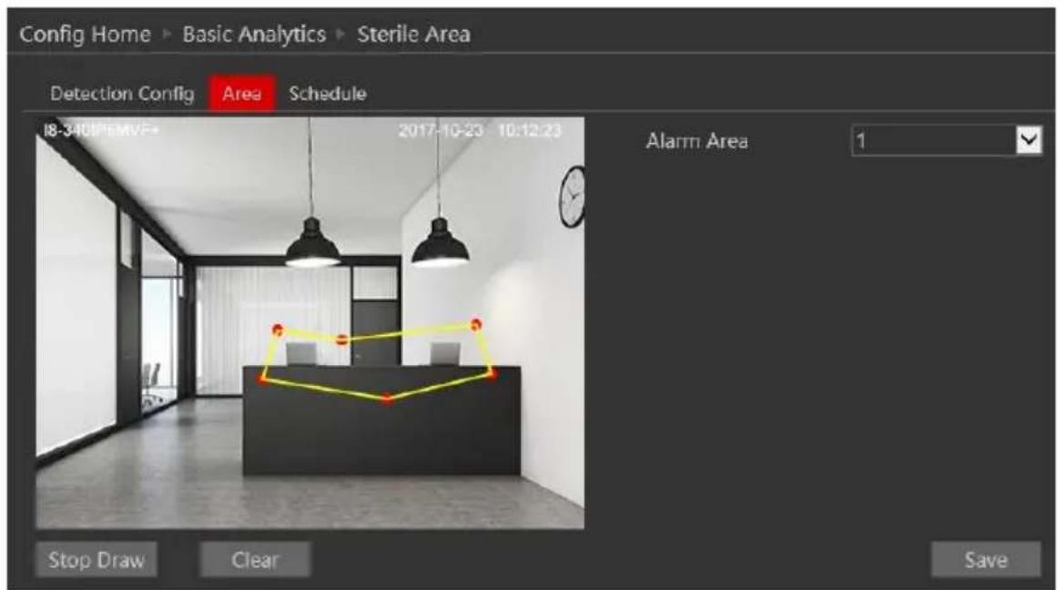
- Click on "Draw Area".
- Draw the area. Drawing the area is done by clicking on the corners of the area you wish to monitor. The maximum points for the polygon are 6. Once you marked the 6^th corner, the camera will automatically connect it with the 1^st point and close the area.
- Click "Save" to confirm the settings.
- You can set up to 4 areas. If you wish to set additional areas, change the alarm area number and repeat stages 6-8.
- Next, you will need to set the schedule. Click on the "Schedule" tab to get the following interface:
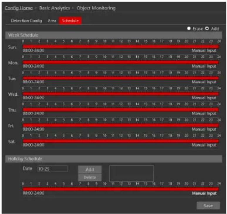
- Set the active alarm time for each of the weekdays. You can also set a holiday schedule and add required dates to it. The holiday schedule overtakes the normal schedule.
4.5.5 Crowd Density
Crowd Density Analytics can detect if there is a gathering of people in a marked area.
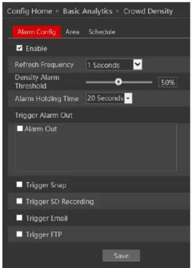
- Go to “Basic Analytics”→“Crowd Density” to get to the interface as shown below:
-
Enable Alarm if required.
-
Set the “Refresh Frequency” to set the time periods between each compare of the scene. The minimum is 0.5 seconds and the maximum is 2 seconds. The default is 1 second.
-
Set the “Density Alarm Threshold”. This setting reflects the percentage of the marked area that will be filled with people.
-
Set the Alarm response as follows and click "Save" to confirm:
| Alarm Triggers: | |
| Alarm Out | triggers the alarm out relay |
| Trigger Snap | takes a snapshot (SD card must be available) |
| Trigger SD Recording | Initiates video recording over the SD card (SD card must be available) |
| Trigger Email | sends an email as configured in the Email section. |
| Trigger FTP | send a snapshot as configured in the FTP section |
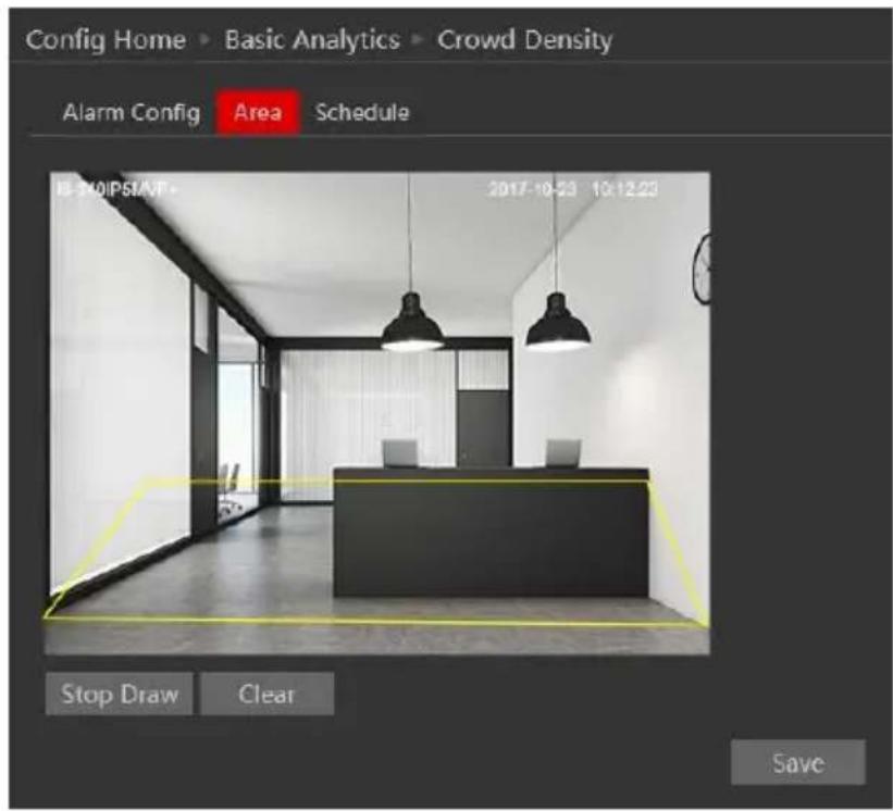
- Now you will have to set the detection area. Click on the "Area" tab to get to the interface shown below.
-
Click on "Draw Area".
-
Define the area. It is shown as a square and cannot be changed. Drag the borders of the square to adjust it.
-
Click "Save" to confirm the settings.
-
Next, you will need to set the schedule. Click on the "Schedule" tab to get the following interface:
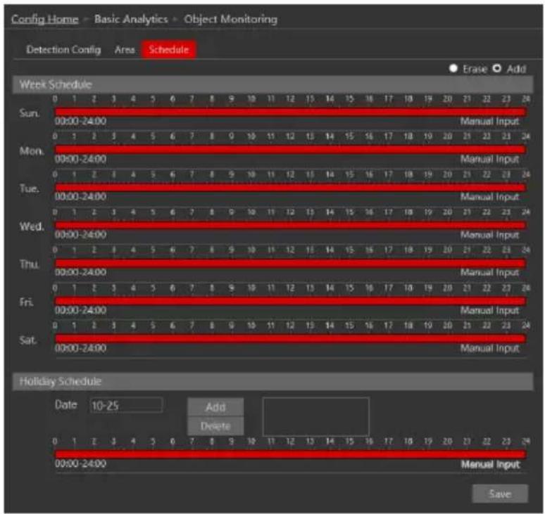
- Set the active alarm time for each of the weekdays. You can also set a holiday schedule and add required dates to it. The holiday schedule overtakes the normal schedule.
4.5.6 People Intrusion
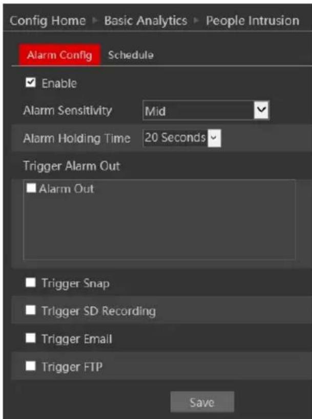
People Intrusion Analytics works like the sterile area but is more oriented to detect human beings other than vehicles, animals or other objects. It is working on the whole scene and cannot be configured for a defined area of the monitored area.
- Go to “Basic Analytics”→“People Intrusion” to get to the interface as shown below:
-
Enable Alarm if required.
-
Set the alarm sensitivity and response as follows and click "Save" to confirm:
| Alarm Triggers: | |
| Alarm Out | triggers the alarm out relay |
| Trigger Snap | takes a snapshot (SD card must be available) |
| Trigger SD Recording | Initiates video recording over the SD card (SD card must be available) |
| Trigger Email | sends an email as configured in the Email section. |
| Trigger FTP | send a snapshot as configured in the FTP section |
- Next, you will need to set the schedule. Click on the "Schedule" tab to get the following interface:
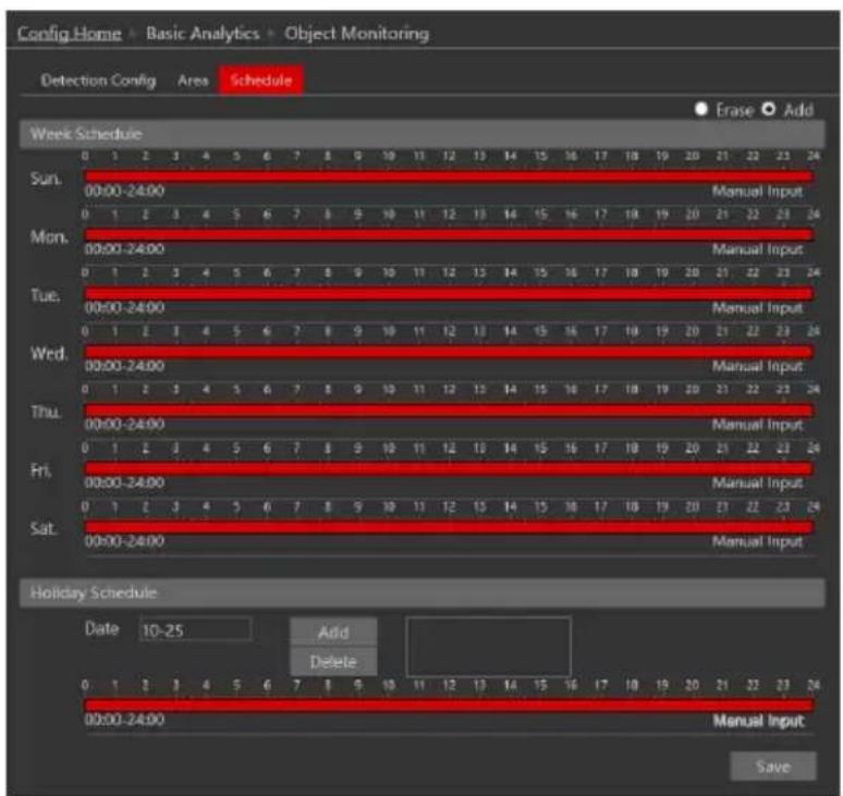
- Set the active alarm time for each of the weekdays. You can also set a holiday schedule and add required dates to it. The holiday schedule overtakes the normal schedule.
4.5.7 People Counting.
People counting analytics will detect the number of people that entered or left a defined area. It will also calculate the number of people that have entered but didn't leave the area.
- Go to “Basic Analytics”→ “People Counting” to get to the interface as shown below:
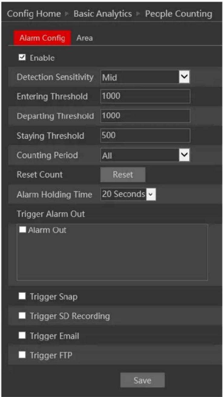
- Enable Alarm if required.
- Set the detection sensitivity.
- Set the “Entering Threshold” – Once the number of people that entered the area will reach the threshold, the alarm will be generated.
- Set the “Departing Threshold” – Once the number of people that left the area will reach the threshold, the alarm will be generated.
- Set the "Staying Threshold" – Once the number of people that are currently in the area will reach the threshold, the alarm will be generated.
- Set the “Counting Period” – The counter will be reset automatically at the end of the defined period.
-
You can manually reset the counter by clicking on the "Reset" button.
-
Set the Alarm response as follows and click "Save" to confirm:
| Alarm Triggers: | |
| Alarm Out | triggers the alarm out relay |
| Trigger Snap | takes a snapshot (SD card must be available) |
| Trigger SD Recording | Initiates video recording over the SD card (SD card must be available) |
| Trigger Email | sends an email as configured in the Email section. |
| Trigger FTP | send a snapshot as configured in the FTP section |
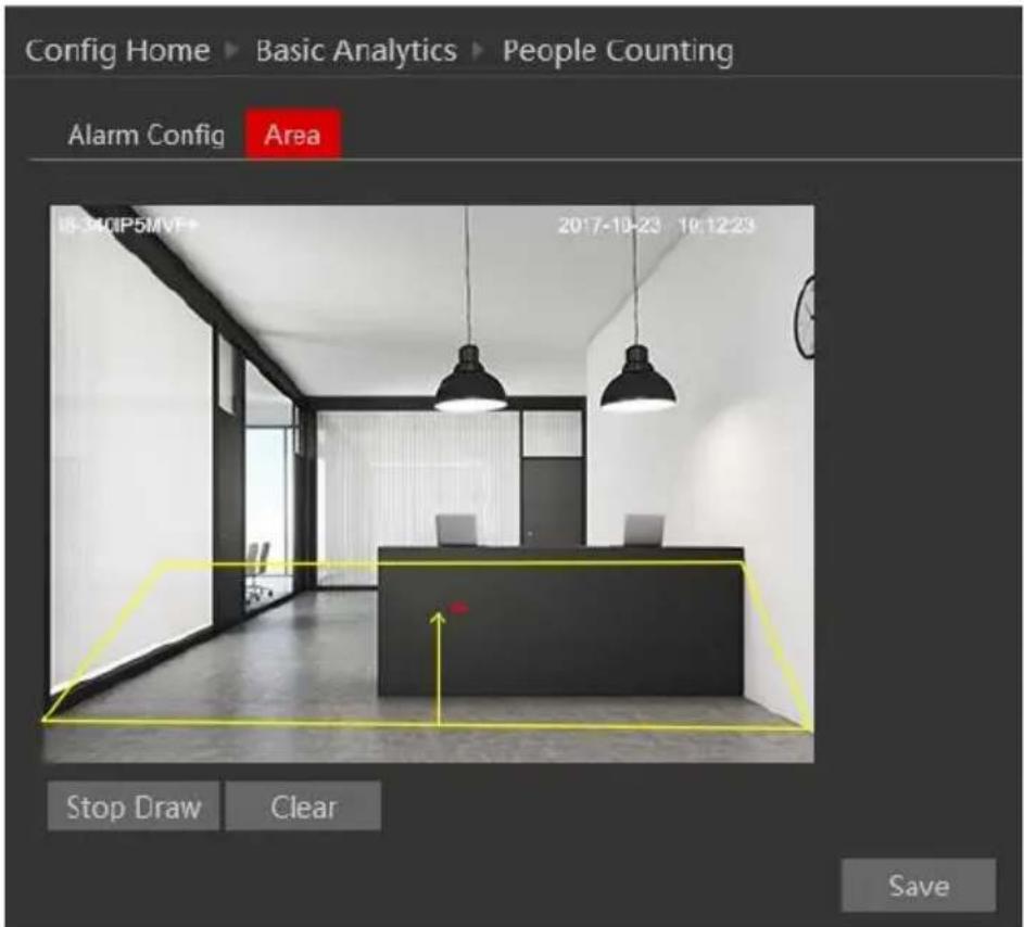
- Now you will have to set the detection area. Click on the “Area” tab to get to the interface shown below.
-
Click on "Draw Area".
-
Define the area. This definition consists out of 2 layers:
A. The entrance: Indicated by a yellow square. Set it around the entrance door/opening. Make sure that it is big enough to allow accurate detection. We recommend a minimum of 50% of the frame. It is shown as a square and cannot be changed. Drag the borders of the square to adjust it.
B. Entrance Direction: Indicated by a red arrow. Set it by clicking on the top/bottom of the arrow and setting it accordingly. The arrow should mark the direction of the entrance. The direction of exit will be the opposite direction.
- Click "Save" to confirm the settings.
Once enabled, the live interface of the camera will show the marked area together with the counter's current state as shown below:
4.5.8 Analytics and Live Display.
Once enabled, the Analytics will appear on the camera's live interface. It will not appear on any other device connected to the camera such as NVR or CMS.
4.6 Network Configuration
Network configuration includes eight submenus: Port, IP Address, Server Configuration, IP Notify, DDNS Config, RTSP, UPnP, Mail Setting, and FTP.
4.6.1 TCP/IP
Go to “Network”→“TCP IP” tab to see the interface shown below. The first and default tab is IPv4 Protocol. There are two options for IP setup: obtain an IP address automatically by DHCP or a defined IP address. You may choose one of the options as required.
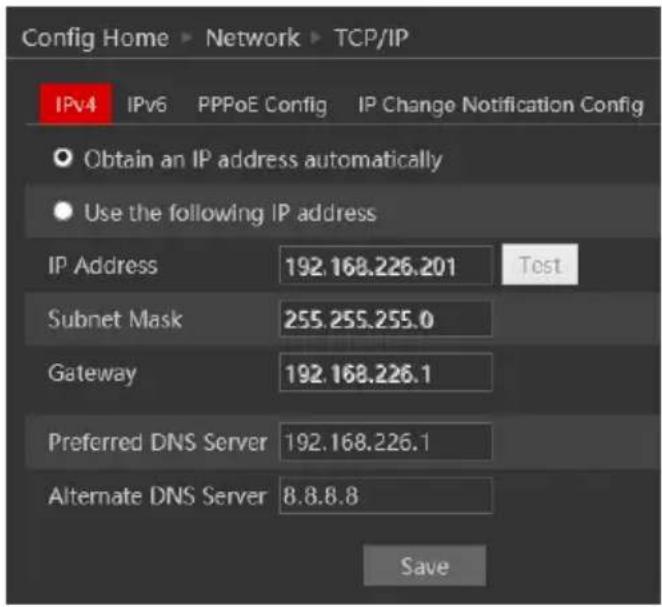
Automatic IP Assignment: Use “Obtain an IP address automatically” for the camera to communicate with an available DHCP server that will assign the camera with an IP address automatically.
Please note:
1) In order for the DHCP mode to work, you must have a DHCP server on the LAN.
2) Using DHCP for permanent installations is not advisable as the IP Address might change after a while and cause the camera to be unreachable.
Manual IP Assignment: If you wish to set static IP addresses, choose “Use the following IP Address”, set the range of IP addresses you wish to assign (First and last address), set the
gateway and subnet mask and click on batch set. Wait for a few moments until the IP manager will configure the cameras. After configuration, the IP addresses of the cameras will refresh automatically.
Please note:
1) The selected IP address must be available.
The next tab is IPv6:
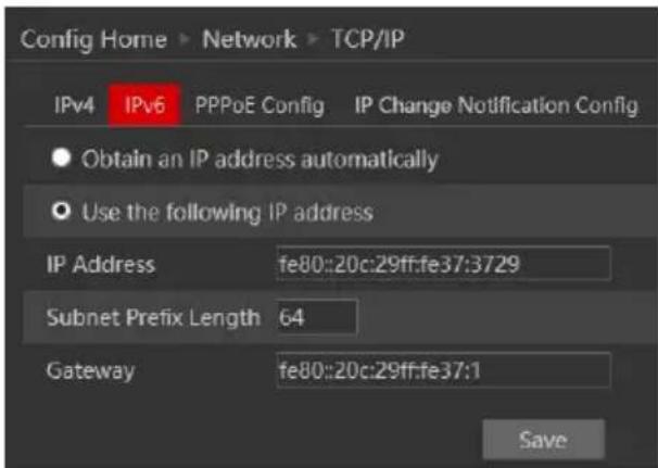
If you need to use IPv6, configure it in the same method as described for IPv4.
The next tab is PPPoE:
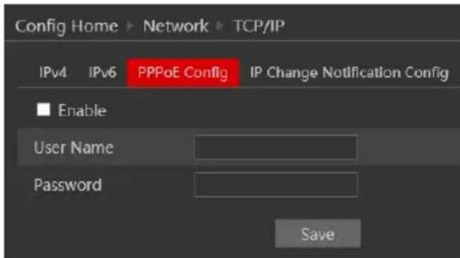
For PPPoE, the user is required to manually input the username and password for dial-up internet. After saving the username/password information set up IP address change notification. Last, connect with Modem and the device will dial-up internet automatically.
Press the "Save" button to save the settings.
The next tab is “IP Change Notification Config”: If you have used DHCP and you need to be notified that the IP Address assigned to the camera was changed, enable it and set Email or FTP for the notification process.
4.6.2 Port
- Go to “Network”→“Port” to see the interface as shown below.
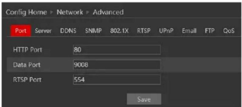
- Input port number for IE access in the "HTTP Port" textbox.
- Input the port number for audio & video transmission in the "Data Port" textbox.
- Set the RTSP port for video/audio transmission over RTSP
4.6.3 Server Configuration
Go to "Network"→ "Server".
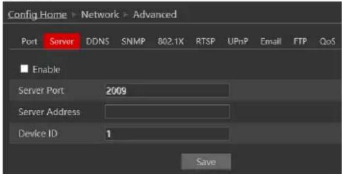
This section refers to "Auto Report Server". Enable it if required.
Auto report server will make the camera to report back to the defined server using the port 2009.
Set the port (default port is 2009. It is advisable not to change it.) Set the server address (usually it is the CMS address which needs to be a static address). Set a unique device ID.
Each of the devices using auto server report should have its own ID.
The Camera will report back to the defined server its current IP using port 2009.
4.6.4 DDNS Configuration
- Enter into "Network"→"DDNS" tab as below:
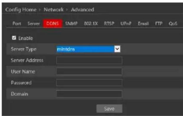
The default choice is Mint-Server which is Provision-ISR's free Domain name Registration (http://www.provision-ISR-dns.com)
Note: DDNS is used to register for a hostname with DDNS username and password.
Provision ISR now allows you to use our mint DDNS server in order to create a virtual address for your security device on the internet. Each account is limited to 35 different addresses using your preferred domain name address instead of using IP addresses. Follow the steps below to register your device's name and to configure your DVR to use Provision ISR's Mint DDNS server.
(a) To register a domain with Provision-ISR DDNS server follow these steps:
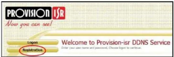
1) Visit our website: http://provision-ISR-dns.com and register for a domain name by clicking "Registration"
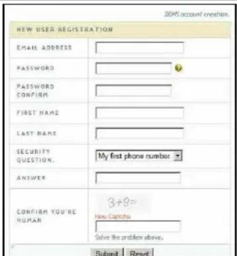
2) Fill in the registration form, then click "Submit"
3) Fill in the hostname you want to apply for and press "Request Domain" (for example "home")
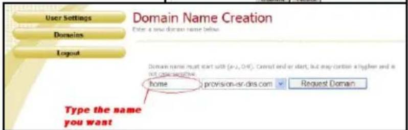
4) If there is no problem with the domain registration you will see the following
message: "Your domain was successfully created."
If you do not see this
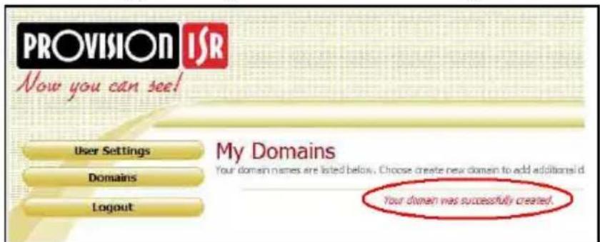
message, the domain name you requested is already in use and you will be requested to provide an alternate domain name (please note: the domain name is sometimes called hostname).
You can create up to 35 domain records under a single account
5) The domain name is added at the beginning of your DVR's address, for example, the domain "home" will appear at home.provision-ISR-dns.com.
Press the "Save" button to save the settings.
4.6.5 SNMP
Simple Network Management Protocol (SNMP) is a popular protocol for network management. It is used for collecting information from and configuring, network devices, such as servers, printers, hubs, switches, and routers on an Internet Protocol (IP) network. In order to Enable and work with SNMP, you need that the switch or another server on the network will support this protocol as well. Though our IPC fully supports SNMP will not explain how to configure it in this manual.
4.6.6 802.1X
The 802.1X standard is designed to enhance the security of wireless and local area networks (WLANs) that follow the IEEE 802.11 standard. 802.1X provides an authentication framework for wireless LANs, allowing a user to be authenticated by a central authority.
4.6.7 RTSP
RTSP is used to stream video/audio using the shared protocol. v4.2 is also supporting RTSP using Multicast protocol.
Go to “Network”→ “RTSP” interface as shown below.
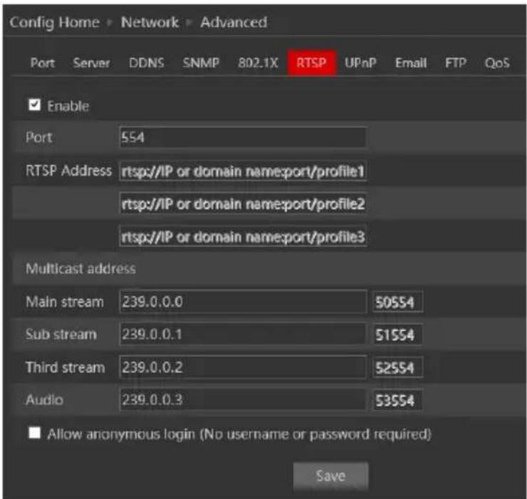
- Enable the RTSP if required.
- RTSP Port: Access Port of the streaming media. The default port is 554.
- RTSP Address: each of the streams have a unique RTSP address. Input the desired address into your RTSP player.
Notice that the camera also support multicast addresses that can be used as well for supporting players. - Enabling “Allow anonymous login” will authorize RTSP connection without the need for username/password.
- Click "Save" to confirm and save settings.
4.6.8 UPnP
Go to “Network”→“UPnP” interface as shown below.
Select "Enable UPnP" and then input friendly name.
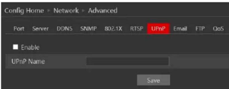
Then double-click “Network” icon on the desktop of the PC to see an icon with the name and IP address of the camera. You may quickly access the device by double-clicking this icon.
4.6.9 Email Setting
Go to “Network” → “Email” interface.
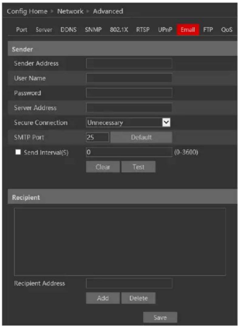
The input fields are as follows:
| Field | Meaning |
| Sender Address | Sender's e-mail address |
| User Name | The username of the Email account |
| Password | The password for the Email account |
| Server Address | The SMTP/Outgoing Email server address |
| Secure Connection | Choose between Unnecessary/SSL/TLS |
| SMTP Port | The SMTP port. The default port will be used according to the secure connection choice but can be edited manually if required. |
| Send Intervals | The minimum time duration between 2 Email that will be sent by the system, |
| Recipient Address | The email addresses that Emails generated by the system will be sent to. |
After all parameters are properly set up, you can click “Test” to confirm that the system can connect to the email server with the provided details. If an email sent successful, a “Test Successful” window will pop up, if not, you should try other email addresses or check and correct the settings.
In order to input new mail recipient, input the recipient address and click on “Add”. The new address will be added to the recipient list box.
Notice: If you change the static IP into PPPoE and select mailbox, there will be an e-mail sent to your mailbox for notifying a new IP address.
4.6.10 FTP
Go to “Network” →“FTP” interface as shown below.
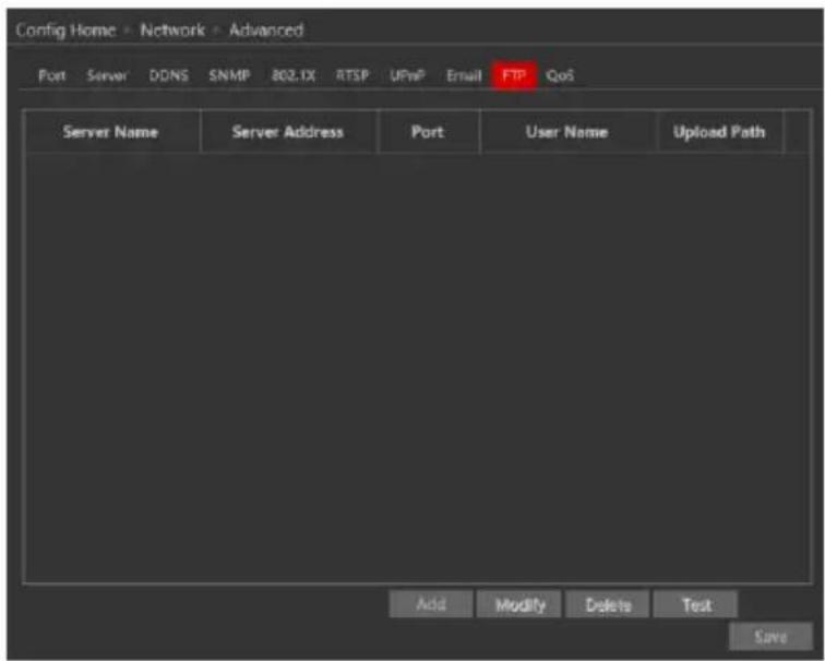
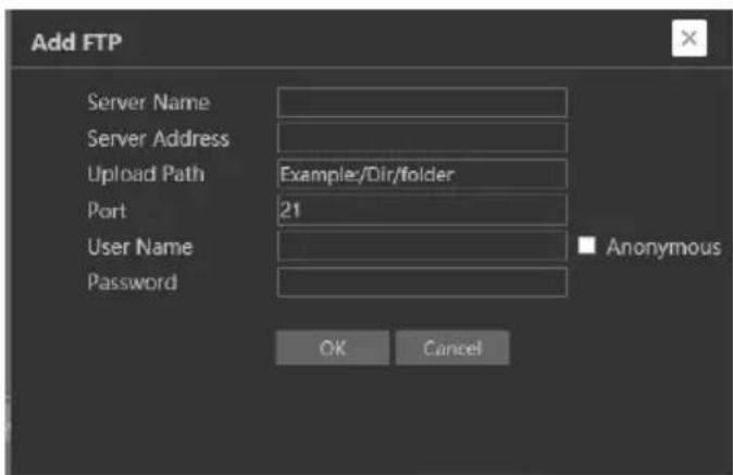
To add a new FTP server click on “Add” and input the FTP server’s server name, address, port number, username, password, and upload path, click OK to confirm the setting.
Click on "Modify" to edit the information of the FTP server
Click on "Delete" to delete the FTP server
Click on “Test” to confirm the setting and availability of the FTP server.
4.6.11 QoS
Quality of Service (QoS) is an advanced feature that prioritizes internet traffic for applications to minimize the impact of busy bandwidth. It must be supported by the switch/router being used.
4.7 Security
Security configuration includes three submenus: User Settings, Online Users, and Block & Allow lists.
4.7.1 User
Go to “Network” → “User” to access the following interface.

Adding a user:
Click on the “Add” button to pop up the “Add user” dialog box.
Input the username, password and confirm the password.
Set the user type. 3 user types are available:
A. Administrator – Can perform all action and settings on the camera.
B. Advanced user – Can view and configure the camera excluding the “User Access” section.
C. Normal User - Can only view the live image and cannot configure.
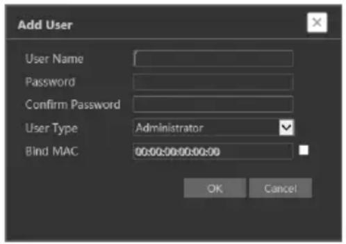
At this stage, you can also bind a MAC address for the user. This means that this user will only be able to connect from a single pre-defined device and his access will be denied if he will try to connect from any other device.
Click on "OK" and "Save"
Modify user:
Select the user you wish to modify and click on the “Modify” button. A modification window will pop up as shown below.
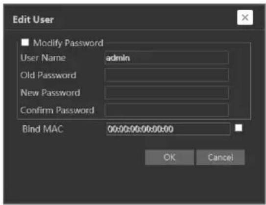
You can change the username if required. If you wish to edit the password of the user, tick “modify password” and input the old password, new password, and confirmation of the new password.
You can also bind a MAC address for the user as explained in the “Add user” section. Click “OK” to save.
Delete user:
Select the user you wish to delete and click on the “Delete” button. A confirmation prompt will pop up. Click “Ok” to confirm.
Note: The default user "admin" cannot be deleted.
4.7.2 Online Users
“Online users” section will allow you to view users who are currently connected to the camera. Administrator level users can also kick out other users who are currently connected to the camera.
Go to “Network” → “Online Users” to access the following interface.

You can view the IP address, port, username and user type used for the connection.
The “Kick Out” button will kick out the selected user and input his IP address to the blacklist. Click on it for the relevant user and confirm the prompt message.
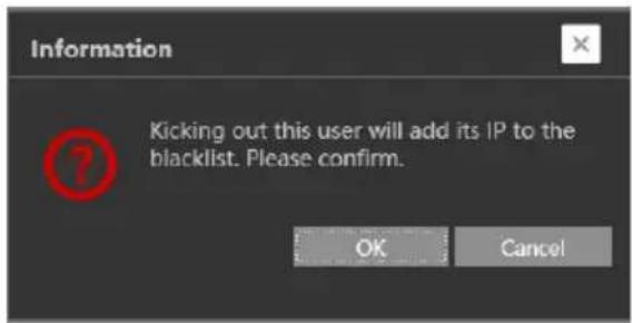
Important Note: once the user is kicked out, the IP address used for connection will be blacklisted. Therefore, the device used for connection will not be able to connect to the camera until the IP address will be manually removed from the blacklist.
4.7.3 Block and Allow Lists
“Block and Allow” lists allow the user to create lists of IP/MAC addresses that will be allowed or denied for connection.
Once a “Block” list is created, all devices except the blocked devices will be allowed to connect to the camera.
Once an “Allow” list is created, all devices except the allowed devices will be blocked from connecting to the camera.
Go to “Network” → “Block and Allow Lists” to access the following interface.
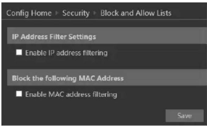
The lists can be based on IP Only / MAC only / Both IP and MAC together.
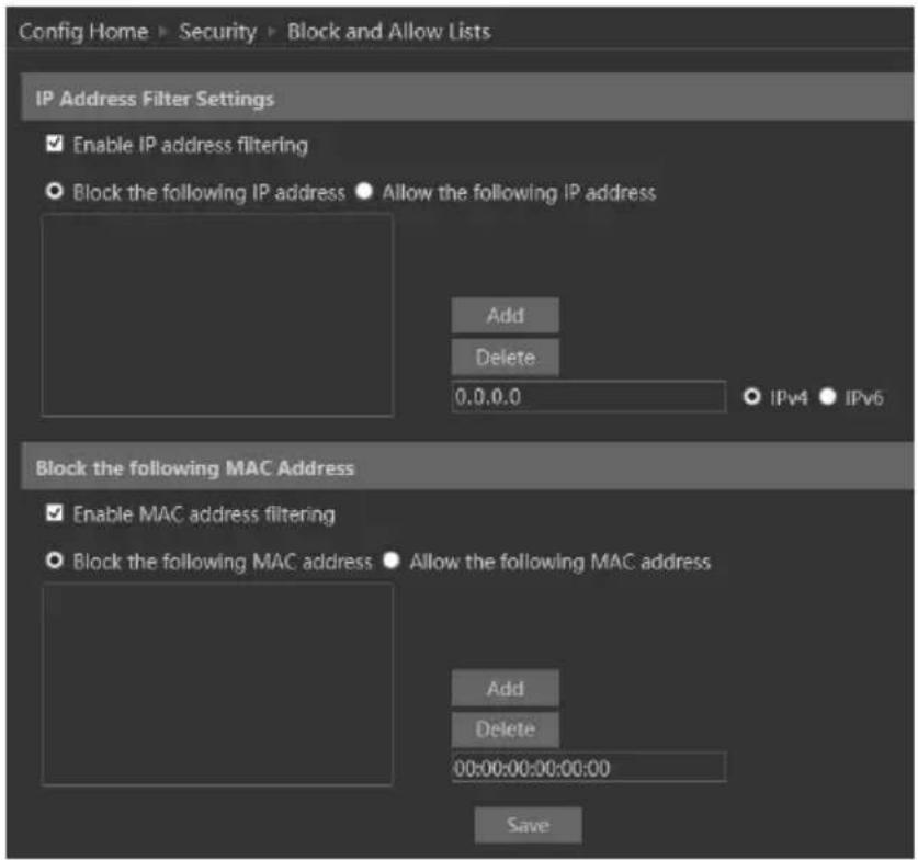
Enable the filtering you wish to activate. For the demonstration, we will enable both IP and MAC filtering, so the instructions below are true for both.
1) Choose the type of list you wish to create (block or allow)
2) Input the IP/MAC address you wish to add to the list
3) Click on add.
4) If you wish to add more than one address, repeat stages 1-3
5) Once finished, click "Save" to confirm, save the settings and enable the lists.
4.8 Maintenance
Maintenance includes 4 submenus: Backup & Restore, Reboot, Upgrade and Operation log.
4.8.1 Configure Backup & Restore
Backup and restore are used to save the camera's configuration on a PC and use it in case the camera's configuration was changed or when you wish to change the configuration of several cameras to be uniformed. This section also allows you to restore the camera's setting to factory default with some exceptions.
Go to "Maintenance"→" Backup and Restore".
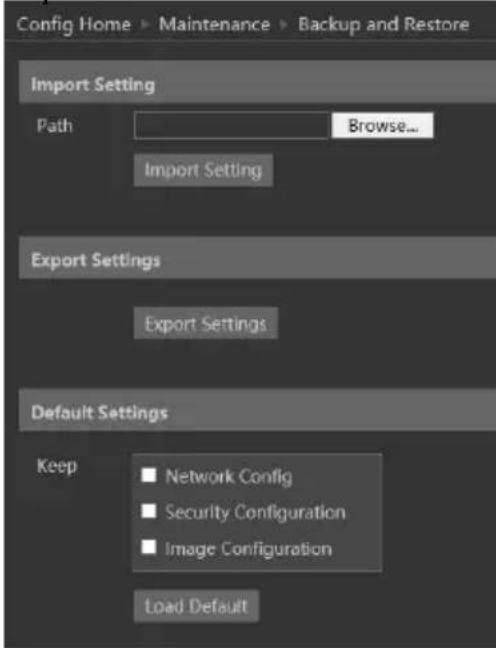
- Importing Settings: If you have a configuration file and you wish to import it to the camera, click on “browse” and choose the relevant config file.
After choosing the file click on “Import settings” and wait for the process to finish. - Exporting settings: If you wish to export the configuration settings of the camera click on “Export”. Choose the location on your PC and set the file name. Click on “OK” to save the file on the desired location.
- Loading factory default: If for any reason you wish to restore your camera settings to factory default, you can use the “Load Default” button. Notice that you can mark some configuration that will be saved:
○ Network Config: Will save all the network section configuration
o Security Configuration: Will save all the security section configuration.
○ Image configuration: Will save the image section configuration.
4.8.2 Reboot Device
Go to “Maintenance”→“Reboot” to see the interface as shown below.
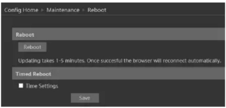
In order to reboot the IPC click on the reboot “Reboot” button and confirm the pop up prompt message, then wait for the reboot process to finish.
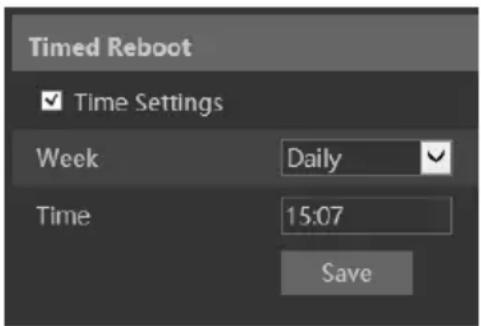
You can also set a scheduled reboot. Tick the “Time Settings” and set the time period and time for the reboot. You can choose a day of the week when the reboot will automatically take place or you can set it to happen on a daily basis. The reboot will occur on the specified day and time.
4.8.3 Upgrade
Go to "Maintenance"→"Update" to open the interface as shown below.

- Click "Browse" button to select the upgrade file.
- Click "Upgrade" button to start the upgrading process of the IPC.
- The device will restart automatically once completed.
- Depending on the update release note, the IPC configuration might reset.
Notice:
1) You must not disconnect to PC or close the IPC during the upgrade process to prevent permanent damage to the camera.
2) The camera update file is ***.TAR. the "TAR" file should not be extracted.
4.9 Playback
Playing back videos taken by the camera have 2 options:
A. Video files/Images saved locally on the PC (If any were taken)
B. Video files/Images saved on the Camera SD card (If available)
To access the playback interface, click on the “Search” Main tab. The interface below will appear.
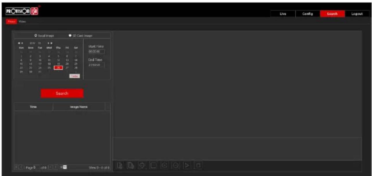
1) First, you will have to choose which type of media you wish to search. On the left top corner choose from Photo and Video
2) Choose the location of the stored media. You can either choose "Local" – which is your PC or you can choose "SD Card" which is the camera's SD Card.
3) If you chose the SD card as the search source you can also define the alarm trigger as follows:
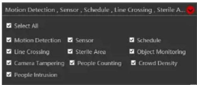
4) Set the search range. You can choose a single day and set a time range of up to 24 hours. (full day). Once finished click on "Search" to show the results.
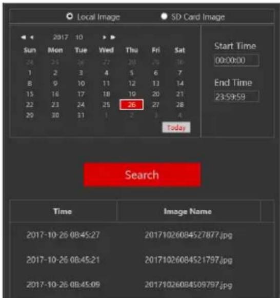
5) Double click on the image/video from the list for it to show on the main playback window and it to the playback queue.

natural_image
Interior view of a modern office with large windows and a desk, no visible text or symbolsThe playback controls are described below. Notice that it is different for Videos and Photos
- For Photos
| Icon | Description | Icon | Description | |
 | Close the displayed image |  | Digital Zoom In | |
 | Close the displayed image and delete the queue list |  | Digital Zoom out | |
 | Download the displayed image to your PC (SD Card search only) |  | Play a slideshow of the queued images | |
 | Download the displayed image and queue list to your PC (SD Card search only) |  | Stop the slideshow | |
 | Fit the image to the screen |  | Dwell time between images | |
 | Display the image in real-size | |||
- For Videos
| Icon | Description | Icon | Description |
 | Play |  | Play next file |
 | Pause playback |  | Enable/Disable Watermark |
 | Stop Playback |  | Download the selected file (SD Card only) |
 | Reduce playback speed |  | Enable/Disable Audio + Volume control |
 | Increase playback speed |  | Full-screen mode |
 | Play previous file |  | Buffering mode selection |
5 Mobile Surveillance
This IPC supports mobile surveillance from internet browsers and iOS/Android mobile phones using Provision-ISR's application “Provision Cam2”
5.1 Network Configuration
- Access the device via LAN
Step 1: Connect device via a wireless router. Then checkmark DHCP both in router and device to automatically acquire IP address or enter the IP address manually.
Step 2: Use WIFI function on your mobile phone to connect the wireless router.
Note: Make sure your phone network and device network are on the same network segment on LAN.
Step 3: Add the IP address and port in the mobile phone surveillance client.
- Access the device via 3G network
Step 1: Set the device network. Please enter Main Menu→Setup→Network tab.
If you use PPPoE to connect the device, please enable PPPoE and input username and password received from your ISP in network tab. Then click “Apply”. You can enter Main Menu→Information→Network tab to see the IP address. If you want to utilize dynamic domain name, please apply for a domain name in a DNS server supported by the device.
If you have a static WAN IP address, please enter Main Menu→Setup→Network tab to input your IP address, gateway, and port.
If you use LAN IP address, please enter Main Menu→Setup→Network tab to input your IP address, gateway and port and then forward IP address and port number in virtual server setup of the router or virtual server(If you have enabled the UPnP function in both the device and router, you can skip this step). Port forwarding setting may be different in different routers and servers. Please refer to the router's manual for details. After you forward your LAN IP address and port, please check the WAN IP address of the router or server.
Step 2: Add the WAN IP address or domain name in mobile phone surveillance client.
6 Q & A
1. Q: How to find my password if I forget it?
A : The default username is "admin" and the default password is "123456".
If you have changed the password and you can't remember it, use the physical reset button on the camera (Press and hold if available) or use the IP Manager to reset the camera to factory default.
Default IP: 192.168.226.201
User name: admin
Password: 123456
2. Q : The IPC fails to connect devices through IE browser, why?
A: Network cable is not connected well. Please check the connection and make sure it is connected securely to the camera.
B: IP was not assigned to an IP.
C: Web port number has been revised: contact an administrator or use the IP manager to get the correct port number.
D: If none of the above worked, recover the IPC's default setting by using the physical reset button on the camera (Press and hold if available) or using the IP Manager to reset the camera to factory default.
Note: Default IP: 192.168.226.201 , mask number: 255.255.255.0
3. Q : IP tool cannot search for devices, why?
A :It may be caused by the anti-virus/firewall software on your computer. Please disable it and try to search device again.
4. Q : IE cannot download ActiveX control. How can I do?
a. Your IE browser probably set to block ActiveX controls. Please perform the following steps:
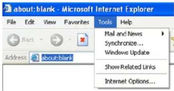
① Open IE browser. Click Tools----Internet Options....
② Select Security----Custom Level....Refer to Fig 4-1
③ Enable all the sub-options under "ActiveX controls and plug-ins". Refer to Fig 4-2
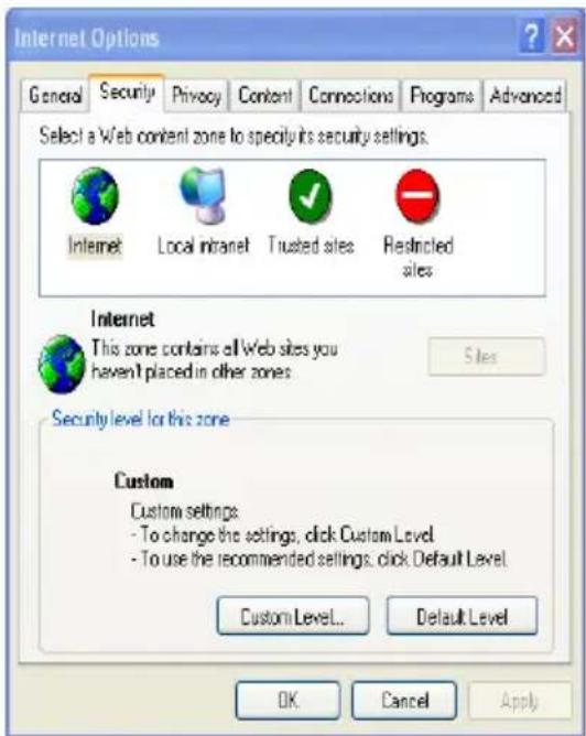
Fig 4-1
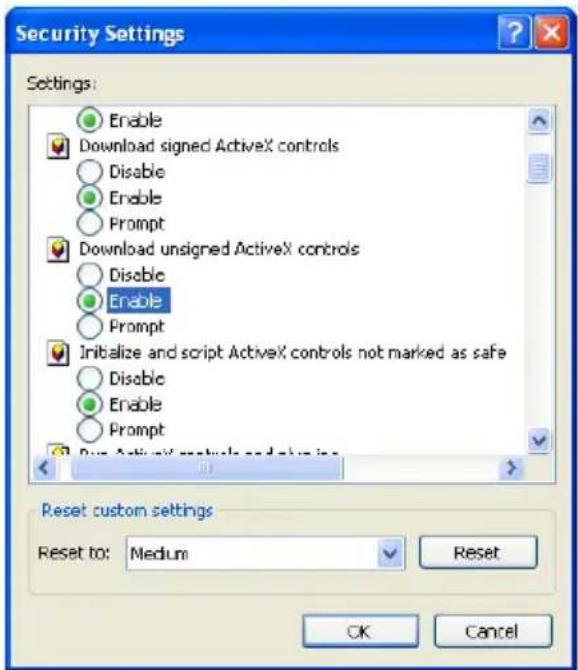
Fig 4-2
④ Click ok to finish setup.
b. Other plug-ins or anti-virus blocks ActiveX. Please uninstall or close them.
5. Q: No sound can be heard, why?
A : Audio input device was not connected. Please connect and try again.
B: Audio was not enabled in the live view interface. Please check the AUDIO item to enable this function.
- IP Series
- This user manual covers the following cameras:
- Eye-Sight:
- Dark-sight
- v4.2 User Manual
- Notes
- Table of Contents
- Introduction....1
- IE Remote Access....2
- Live Preview 6
- IPC Configuration 8
- IP CAMERA USER MANUAL
- Introduction
- Main Features
- IE Remote Access
- LAN
- Access through IP-Manager
- Please note:
- Direct Access through IE
- WAN
- Live Preview
- The Live Preview Interface
- Icons and operation buttons:
- MVF (Motorized Vari-Focal) Controls\*
- RS-485 (PTZ) Controls
- IPC Configuration
- System Configuration
- Basic Information
- Date & Time Configuration
- Setting steps:
- Local Config
- Storage
- Video Configuration
- Camera Configuration
- Video/Audio
- OSD Configuration
- Video Mask
- To set up video mask
- ROI Configuration
- Zoom/Focus\*
- PTZ Configuration
- Protocol
- Alarm Configuration
- Motion Detection
- General Fault
- Alarm In
- Alarm Out
- Basic Analytics
- Object Monitoring
- Camera Tampering
- Line Crossing
- Sterile Area
- Crowd Density
- People Intrusion
- People Counting.
- Analytics and Live Display.
- Network Configuration
- TCP/IP
- Port
- Server Configuration
- DDNS Configuration
- To register a domain with Provision-ISR DDNS server follow these steps:
- SNMP
- 802.1X
- RTSP
- UPnP
- Email Setting
- FTP
- QoS
- Security
- User
- Adding a user:
- Modify user:
- Delete user:
- Online Users
- Block and Allow Lists
- Maintenance
- Configure Backup & Restore
- Reboot Device
- Upgrade
- Notice:
- Playback
- Mobile Surveillance
- Network Configuration
- - Access the device via LAN
- - Access the device via 3G network
- Q & A
- Q: How to find my password if I forget it?
- Q : The IPC fails to connect devices through IE browser, why?
- Q : IP tool cannot search for devices, why?
- Q : IE cannot download ActiveX control. How can I do?
- Q: No sound can be heard, why?
Brand : Provision-ISR
Model : I4-340AHDVF
Category : Security Camera