MSR930 - Router HP - Free user manual and instructions
Find the device manual for free MSR930 HP in PDF.

| Product Type | Multi-service Router |
| Brand | HP |
| Model | MSR930 |
| Dimensions (W x D x H) | 270 mm x 200 mm x 44 mm |
| Weight | 0.9 kg |
| Power Supply | AC 100-240V, 50/60 Hz, external adapter |
| Power Consumption | 15 W typical |
| Ethernet Ports | 4 x 10/100/1000 LAN, 1 x 10/100/1000 WAN |
| USB Ports | 1 x USB 2.0 (for storage or 3G/4G modem) |
| Console Port | 1 x RJ45 console |
| Wireless Support | Optional (requires HP MSR-Wi-Fi card) |
| VPN Support | IPsec, L2TP, GRE, SSL VPN |
| Firewall | Stateful packet inspection, ACL, NAT |
| QoS | Traffic shaping, priority queuing |
| Routing Protocols | Static, RIP, OSPF, BGP |
| Management | Web GUI, CLI (telnet/SSH), SNMP |
| Operating Temperature | 0°C to 40°C |
| Storage Temperature | -10°C to 70°C |
| Humidity | 10% to 90% non-condensing |
| Mounting | Desktop or 19-inch rack mount (brackets included) |
| LED Indicators | Power, Status, WAN, LAN, USB |
| Cleaning | Use a dry cloth; avoid liquids and solvents |
| Safety | Ensure proper ventilation; do not cover vents |
| Spare Parts | Power adapter, mounting brackets; other parts not user-serviceable |
| Repairability | No user-serviceable components inside; contact HP support |
Frequently Asked Questions - MSR930 HP
User questions about MSR930 HP
0 question about this device. Answer the ones you know or ask your own.
Ask a new question about this device
Download the instructions for your Router in PDF format for free! Find your manual MSR930 - HP and take your electronic device back in hand. On this page are published all the documents necessary for the use of your device. MSR930 by HP.
USER MANUAL MSR930 HP
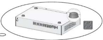
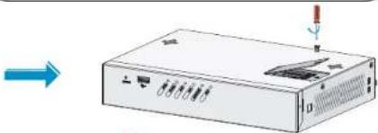
Introduction of Installation Accessories

Wear an ESD-preventive wrist strap, and make sure that the wrist strap has a good skin contact and is well grounded.

Grounding cable

Rubber pads

Screw and anchor kit (User supplied)

M3 screw (user supplied)

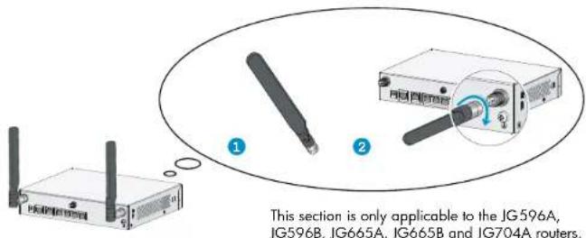
WIFI antenna

GPS antenna

M6 screw (User supplied)

3G antenna

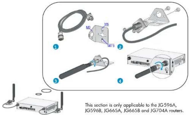
3G/4G antenna cable

3G/4G antenna bracket

4G antenna
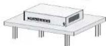
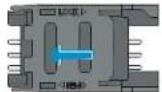
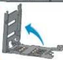
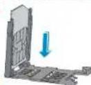
Mounting the Router to a Workbench
Stick the rubber pads to the appropriate positions on the router bottom
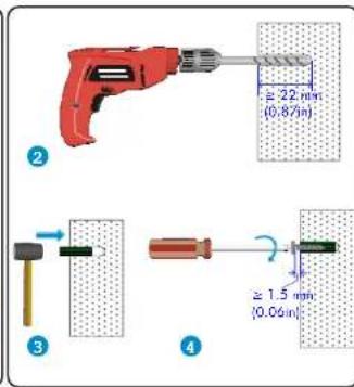
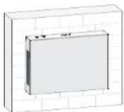
Wall Mounting
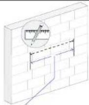
180mm(7.09in), JGS11A, JGS11B, JGS12A, JGS12B, JH012A, JH012B, JGS13A, JGS13B, JGS96A, JGS96B, JG665A, JG665B, JG704A
240mm(9.45in): JG514A, JG514B, JG515A, JG515B, JG531A, JG531B, JG516A, JG516B, JG517A, JG517B, JG518A, JG518B, JG519A, JG519B, JG520A, JG520B, JG597A, JG597B, JH013A
natural_image
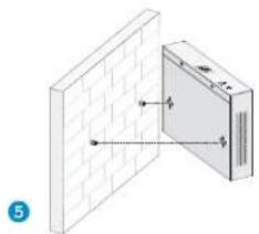
Diagram showing a brick wall and a rectangular panel with dimension lines, no text or symbols present

The chassis size varies with router models. When you drill holes on a wall, see the hole separations in the diagram for reference.
When you mount the router on a wall, position the router so the Ethernet ports face downwards, and the sides with ventilation openings are perpendicular to the ground.
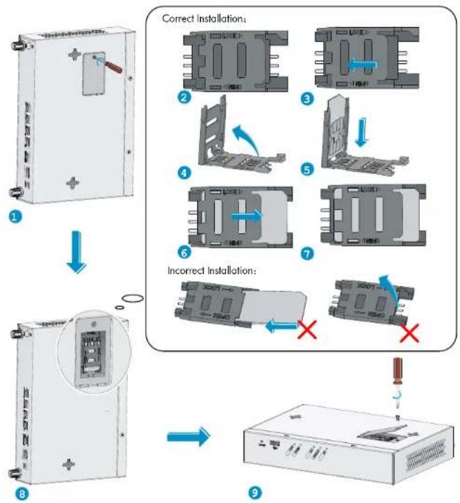
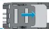
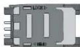
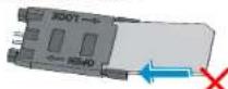
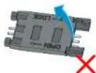
Installing 3G Standard SIM cards

Support RF bands:
- 3G: 800/850/900/1900/2100MHz WCDMA/HSDPA/HSUPA/HSPA- - 2G: 850/900/1800/1900MHz GSM/GPRS/EGPRS
flowchart
graph TD
    A["1: Initial device"] --> B["2: Correct installation"]
    B --> C["3: Incorrect installation"]
    C --> D["4: Correct installation"]
    D --> E["5: Correct installation"]
    E --> F["6: Incorrect installation"]
    F --> G["7: Correct installation"]
    G --> H["8: Incorrect installation"]
    H --> I["9: Correct installation"]

    style A fill:#f9f,stroke:#333
    style B fill:#ccf,stroke:#333
    style C fill:#cfc,stroke:#333
    style D fill:#fcc,stroke:#333
    style E fill:#cff,stroke:#333
    style F fill:#ffc,stroke:#333
    style G fill:#cfc,stroke:#333
    style H fill:#fcc,stroke:#333
    style I fill:#ffc,stroke:#333
This section is only applicable to the JG513A, JG513B, JG515A, JG515B,
routers.JG531A, JG517A, JG517B, JG520A and JG520B
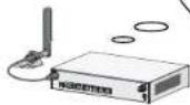
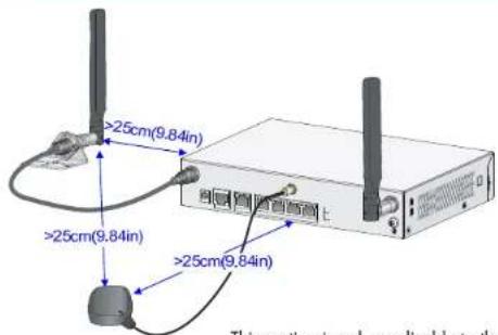
Installing the 3G Antenna

A 3G module is provided with a 3G antenna and a 3G extender cable. Connect the 3G antenna to the port marked "MAIN" by using the 3G extender cable. Ensure a minimum of 25 cm (9.84 in) distance between the 3G antenna and the chassis and between the 3G antenna and any other antenna installed on or connected to the router.


When a second 3G antenna is required, purchase the other 3G antenna and 3G extender cable yourself. Attach the second 3G antenna to the port marked "DIV" if no antennas are installed on the router or connect the second 3G antenna to the port marked "DIV" by using the 3G extender cable if the router has antennas installed. Ensure a minimum of 25 cm (9.84 in) distance between the 3G antenna (when the extender cable is used) and the chassis and between the 3G antenna and any other antenna installed on or connected to the router.
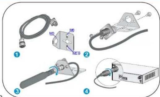
This section is only applicable to the JG513A, JG513B, JG515A, JG515B, JG531A, JG517A, JG517B, JG520A and JG520B routers.
Installation Guidelines for Dual-3G Routers
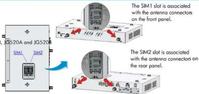
This section is only applicable to the JG531A and JG531B routers.

On a dual-3G JG531A and JG531B router, the SIM1 and SIM2 slots are associated with the antenna connectors on the front and rear panels, respectively.
Installing the WIFI Antenna
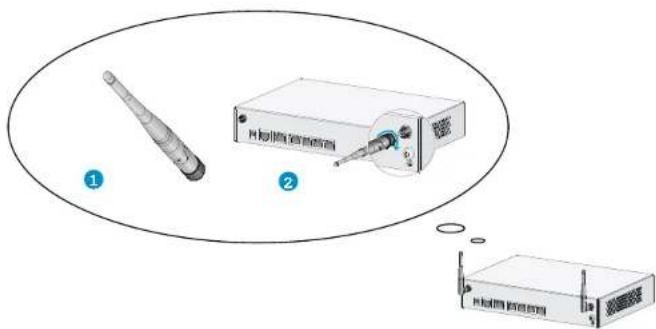
This section is only applicable to the JG512A, JG512B, JH012A, JH012B, JG519A, JG519B, JH013A, JG597A and JG597B routers.
Installing 4G Standard SIM cards

JG596A Support RF bands:
4G: 700MHz LTE
3G: 800/1900MHz CDMA
JG704A Support RF bands:
4G: 700/1700/2100MHz LTE
3G: 800/850/1900/2100MHz WCDMA/HSDPA/HSUPA/HSPA+/DC-HSPA+
2G: 850/900/1800/1900MHz GSM/GPRS/EDGE
JG665A Support RF bands:
• 4G: DD800/900/1800/2100/2600MHz LTE
• 3G: 900/2100MHz WCDMA/HSDPA/HSUPA/HSPA+
• 2G: 900/1800/1900MHz GSM/GPRS/EDGE

JG596B Support RF bands:
• 4G: 2100/1700/700/850/1900MHz LTE
• 3G: 2100/1900/1700/850/900MHz UMTS/HSDPA/HSUPA/HSPA+/DC-HSPA+
800/1900MHz CDMA
• 2G: 1900/1800/900/850MHz GSM/GPRS/EDGE
JG665B Support RF bands:
• 4G: DD800/900/1800/2100/2600MHz LTE
• 3G: 900/2100/850/800/1900MHz UMTS/HSDPA/HSUPA/HSPA+/DCHSPA+
• 2G: 850/900/1800/1900MHz GSM/GPRS/EDGE
natural_image
Illustration of a rectangular electronic device with a switch and mounting holes (no text or symbols)1
Correct Installation:
2
③
4
5
6
7
Incorrect Installation:
natural_image
Illustration of a server rack with ports and indicator lights, showing no text or symbols9
This section is only applicable to the JG596A, JG596B, JG665A, JG665B and JG704A routers.

Installing the 4G Antenna
When you install two 4G antennas on a JG704A router, connect one or both of the antennas to the router by using antenna extender cables.
Installing the 4G Extender Cable
One 4G antenna extender cable is provided with the HP JG704A router. No 4G antenna extender cable is provided with other router models. Purchase 4G antenna extender cables as required.
Installing the GPS antenna
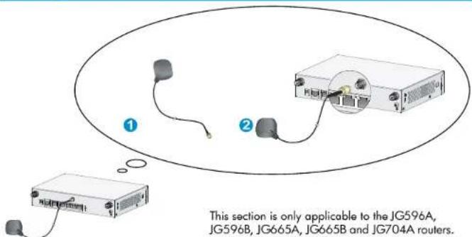
JG704A router antenna installation instructions
⚠ Ensure a minimum distance of 25 cm (9.84 in) between any two antennas on the router and between a GPS antenna or a 4G antenna (when an extender cable is used) and the router.
This section is only applicable to the JG704A routers.

Connecting the Grounding Cable
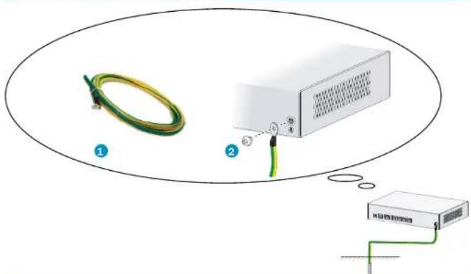
Properly connect the router grounding cable since it is crucial to the lightning protection and electromagnetic shield (EMS) of your router.
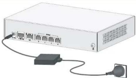
Connecting the Power Cable
Before connecting the power cable, make sure that the device is correctly grounded. Connect the power cable to the router first and then to the equipment-room power supply system to avoid bodily injury.
natural_image
Illustration of a network switch device with ports and cable (no text or symbols)
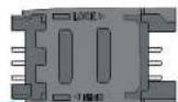
Device Module List
HP MSR93X routers include:
Device Description
JH012A/JH012B HP MSR930 Wireless Router (NA)
JH013A HP MSR935 Wireless Router (NA)
JG511A/JG511B HP MSR930 Router
JG512A/JG512B HP MSR930 Wireless Router
JG513A/JG513B HP MSR930 3G Router
JG514A/JG514B HP MSR931 Router
JG515A/JG515B HP MSR931 3G Router
JG516A/JG516B HP MSR933 Router
JG517A/JG517B HP MSR933 3G Router
JG518A/JG518B HP MSR935 Router
JG519A/JG519B HP MSR935 Wireless Router
JG520A/JG520B HP MSR935 3G Router
JG531A/JG531B HP MSR931 Dual 3G Router
JG596A/JG596B HP MSR930 4G LTE/3G CDMA Router
JG597A/JG597B HP MSR936 Wireless Router
JG665A/JG665B HP MSR930 4G LTE/3G WCDMA Global Router
JG704A HP MSR930 4G LTE/3G WCDMA ATT Router
Documentation
For more information about the installation, see HP MSR93X Routers Installation Guide.
© Copyright 2015 Hewlett-Packard Development Company, L.P.
The information contained herein is subject to change without notice.
Web Configuration Preparation
- Connect the PC to the GE LAN interface of the device.
- Assign the PC on IP address of the subnet 192.168.1.0/24 (except 192.168.1.1), for example, 192.168.1.2.
- Run the Web browser and enter http://192.168.1.1 in the address bar. The IP address 192.168.1.1 is the default login IP address for the device, and it is modifiable after login.
- Enter login information to log on to the device. Both the default username and password are admin, and they are modifiable after login.
Figure 1 Web user login

Quick Configuration Wizard
- From the navigation tree, select Wizard > Basic Configuration Wizard. The page for basic configuration wizard as shown in Figure 2 appears.
- Click Next to enter the page for setting WAN interface parameters. You can set WAN interface parameters manually, automatically, or through PPPoE.
Figure 2 Basic configuration wizard page
Welcome to use the basic configuration wizard
This wizard guides you through the basic configurations on the device.
Click Next to continue.

Figure 3 Setting WAN interface parameters
Set WAN Interface Parameters
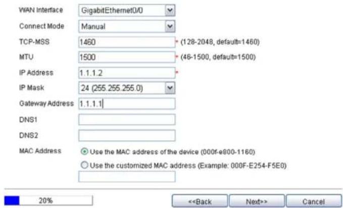
3. Click Next.
On the page as shown in Figure 4, you can perform the following configurations:
Modify the IP address of VLAN-interface 1. Make sure VLAN-interface 1
LAN and the interface of the
interface are on the same subnet.
- Enable DHCP to assign IP addresses, gateway address, and DNS server addresses to hosts or devices that connect to the GE LAN interface.
Figure 4 Setting LAN interface parameters
Set LAN Interface Parameters
| VLAN Interface.1 | |
| IP Address: | 192.168.1.1 |
| Subnet Mask: | 255.255.255.0 |
| DHCP Server: | |
| Enable Disable | |
| Start IP Address: | 192.168.1.100 |
| End IP Address: | 192.168.1.200 |
| Gateway IP Address: | 192.168.1.1 |
| DNS Server 1: | |
| DNS Server 2: | |
Note
- For the DHCP server to work properly in case the IP address/subnet mask of a LAN interface changes, ensure that the address pool configured on the DHCP server is on the same network segment as the new IP address of the LAN interface.
- Modification of the IP address of the LAN interface may result in disconnection with the device. Perform the operation with caution.


4. Click Next.
The page that displays basic configuration summary appears
Figure 5 Complete basic configuration wizard page
Complete Basic Configuration Wizard
| LAN Interface Parameters | |
| VLAN Interface | :1 |
| IP Address | :192.168.1.1 |
| Server Node | 74620255.0 |
| Dhcp Server Parameters | |
| DHCP Server | :Enable |
| Start IP Address | :192.168.1.100 |
| End IP Address | :192.168.1.200 |
| Gateway IP Address | :192.168.1.1 |
| DNS Server 1 | : |
| DNS Server 2 | : |
| WAN Interface Parameters | |
| WAN Interface | :GigabitEthernet0/0 |
| Connect Mode | :Manual |
| TCP-NOG | :1660 |
Save Current Configuration

5. Verify the configuration and click Finish.
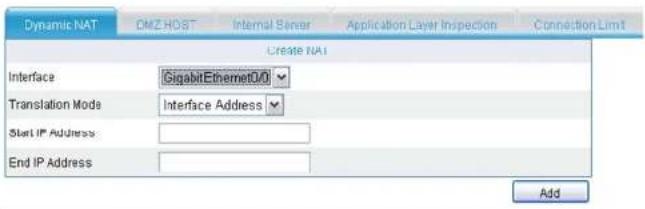
Configuring NAT
- From the navigation tree, select NAT Configuration > NAT Configuration. The page for dynamic NAT configuration as shown in Figure 6 appears. You can set the translation mode to Interface Address, PAT, or No-PAT.
Figure 6 Dynamic NAT configuration page
Select the NAT(s) you want to remove
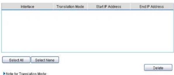
2 Click Add.
Documentation
For more information about the installation, see HP MSR Router Series Web-based Configuration Guide (V5).