SPP160-MC4 - Solar panel Projecta - Free user manual and instructions
Find the device manual for free SPP160-MC4 Projecta in PDF.

| Product Type | Solar Panel |
| Brand | Projecta |
| Model | SPP160-MC4 |
| Power Output | 160W |
| Cell Type | Monocrystalline |
| Dimensions | 1480 x 670 x 35 mm |
| Weight | 12 kg |
| Open Circuit Voltage (Voc) | 22.5 V |
| Short Circuit Current (Isc) | 9.2 A |
| Maximum Power Voltage (Vmp) | 18.5 V |
| Maximum Power Current (Imp) | 8.65 A |
| Connector Type | MC4 |
| Frame Material | Aluminum |
| Glass Type | Low iron tempered glass |
| Operating Temperature | -40°C to +85°C |
| Maximum System Voltage | 1000V DC |
| Warranty | 25 years power output, 5 years materials |
| Maintenance | Clean with soft cloth and mild soap; avoid abrasive materials |
| Safety Precautions | Do not look directly at sun; avoid shading; use with charge controller |
| Spare Parts | MC4 connectors, junction box |
| Repairability | Diode replacement possible; professional repair recommended |
Frequently Asked Questions - SPP160-MC4 Projecta
User questions about SPP160-MC4 Projecta
0 question about this device. Answer the ones you know or ask your own.
Ask a new question about this device
Download the instructions for your Solar panel in PDF format for free! Find your manual SPP160-MC4 - Projecta and take your electronic device back in hand. On this page are published all the documents necessary for the use of your device. SPP160-MC4 by Projecta.
USER MANUAL SPP160-MC4 Projecta
natural_image
Close-up of a black solar panel with grid lines, no visible text or symbols
natural_image
Close-up of a black solar panel with grid lines, no visible text or symbolsWARNING
- For installations with lead acid batteries, avoid sparks or flames near the batteries and always use proper eye protection.
- Given sufficient light, solar panels always generate energy even when they are disconnected. Accidental 'shorting' of the terminals or wiring can result in sparks causing personal injury or a fire hazard. It is recommended that the front face of the panel(s) are covered with a soft cloth to block incoming light during installation and wiring.
- When connecting panels in series do not exceed 24VDC (Max. 2 panels).
- Do not scratch or bend solar panels.
- Do not disassemble the solar panel frame.
- When mounting solar panels at a height adhere to all relevant safety regulations.
- For fixed installations ground the frame of the solar panel(s) to reduce lightning hazard.
- Do not walk on modules.
- Do not attempt to increase module output by concentrating light on its surface with mirrors.
- Be sure to use components (cables, fuses, etc) with ratings greater than 25% of solar panel/s maximum current ratings.
FEATURES
COMPACT AND POWERFUL
Polycrystalline solar panels are manufactured from a solar cell that is cast from silicon. These cells are more efficient at producing power than an amorphous panel, so the size of the panel is smaller yet produces greater output power.
HEAVY DUTY FRAME
Corrosion resistant frames are constructed to withstand wind speeds in excess of 130 km/h in typical ground mounted applications. The frames are clear anodized and the inner corner connection has a strong mechanical resistance to weather.
TEMPERED LOW IRON GLASS
Clear encapsulated insulation enhances solar cell performance and provides proven weather protection, Tempered low iron glass provides both better impact resistance and better light transmission, allowing the generation of more electricity by reducing the quantity of light that is reflected away from the module.
SPECIFICATIONS
Table 1
| SPP80-MC4 SPP120-MC4 SPP135-MC4 SPP150-MC4 | ||||
| TYPE Polycrystalline Polycrystalline Polycrystalline Polycrystalline | ||||
| RATED POWER 80W 120W 135W 150W | ||||
| OPEN CIRCUIT 21.5V 21.5V 21.5V 21.5V VOLTAGES | ||||
| SHORT CIRCUIT 5.04A 7.55A 8.5A 9.44A CURRENT | ||||
| PEAK POWER 17.5V 17.5V 17.5V 17.5V VOLTAGE | ||||
| PEAK POWER 4.58A 6.86A 7.72A 8.58A CURRENT | ||||
| TEST 1000W/m ^2 CONDITIONS 25°C | 1000W/m ^2 25°C | 1000W/m ^2 25°C | 1000W/m ^2 25°C | 1000W/m ^2 25°C |
| SPP80-MC4 SPP120-MC4 SPP135-MC4 SPP150-MC4 | ||||
| BATTERY SIZES(1 Panel) | 250–900CCA(automotive) | 250–1200CCA(automotive) | 300–1300CCA(automotive) | 350–1400CCA(automotive) |
| 300–1000MCA(marine) (marine) | 350–1500MCA(marine) (marine) | 400–2000MCA | 500–2200MCA | |
| 30–140Ah(deep cycle) | 40–200Ah(deep cycle) | 50–240Ah(deep cycle) | 60–260Ah(deep cycle) | |
INSTALLATION
PLACEMENT
Locate the panel in a position where it is exposed to the sun for the majority of the day. For best results use a northern orientation. Make sure that the front side (dark side) of the solar panel faces the sun. Although the panel will function in the horizontal position, for best performance tilt the panel towards the sun especially during the winter months in the southern states. The angle of the tilt should be similar to the angle of the sun so that the panel is perpendicular to the sun rays. Recommended angles for Indonesian, Australian & New Zealand latitudes are shown below:

Suggested solar panel angles for regions in Australia and New Zealand
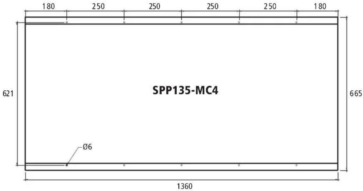
MOUNTING
The panels are supplied with four or eight mounting holes (depending on the model). Use suitable fasteners and mount the panel to a flat surface or mounting frame as per fig. 1, 2 & 3. Ensure the battens or frame does not twist or bend the solar panel's aluminium frame.
FIG 1
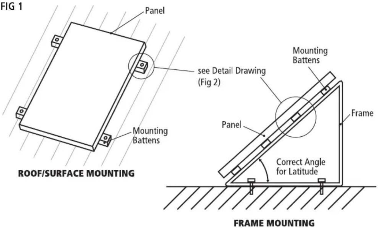
FIG 2
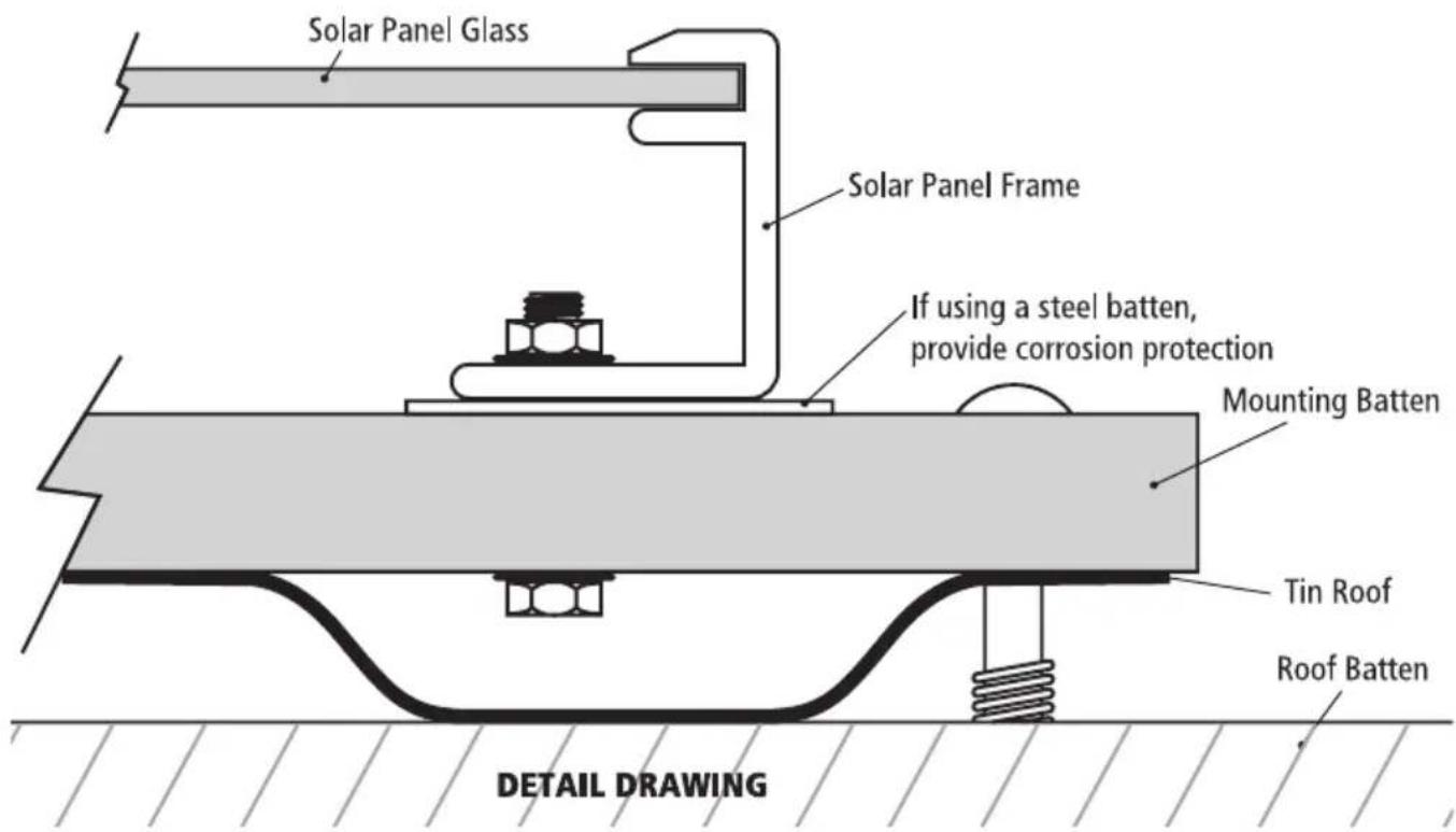
FIG 3
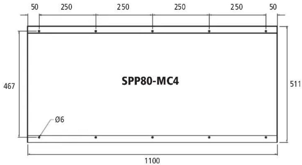
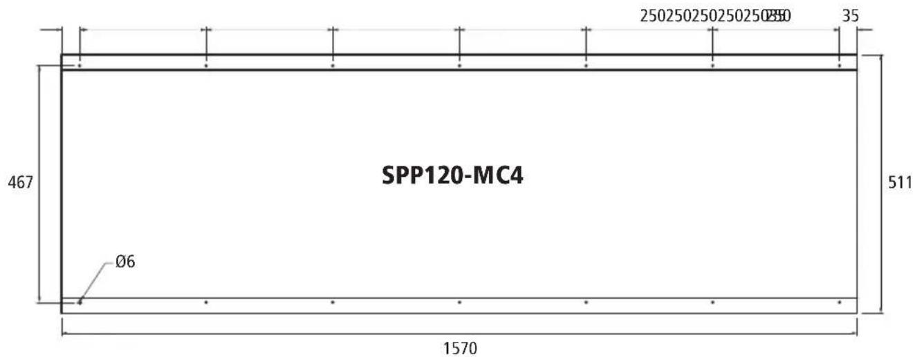
FIXING HOLE DIMENSIONS (NOT DRAWN TO SCALE)
FIG 3 (continued)
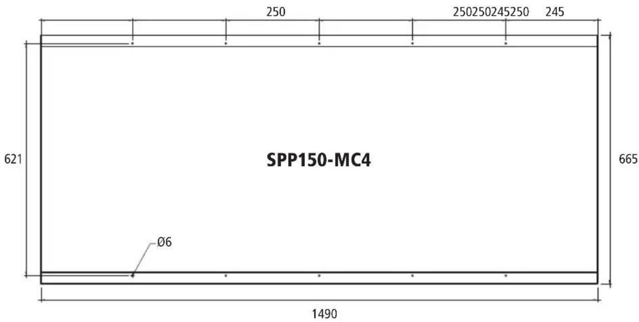
FIXING HOLE DIMENSIONS (NOT DRAWN TO SCALE)
CHARGE CONTROL
Solar panels are most commonly used to charge lead acid batteries. Projecta solar panels are designed to charge 12 VDC batteries. 24VDC batteries can be charged using 2 panels wired in series and using a 24VDC solar charge controller.
For battery charging it is recommended that you use a Solar Charge controller to prevent the battery from being overcharged (damaged) and prevent the battery from discharging (loosing power) into the solar panel at night. Solar Charge controllers are connected between the solar panel and the battery.
Projecta 12VDC Solar Charge controllers:
P/No. SC005 - 7 AMP Automatic Solar Charge Controller (suitable) for solar panels up to 80W.
P/No. SC010 - 10 AMP Automatic Solar Charge Controller (suitable) for solar panels up to 120W.
P/No. SC030 - 30 AMP Automatic Solar Charge Controller (suitable) for solar panels up to 360W.
Projecta 12 & 24VDC Solar Charge Controllers:
P/No. SC320 & SC320D - 20 AMP Automatic Solar Charge Controller (suitable) for solar panels up to 240W.
P/No. SC330 - 30 AMP Automatic Solar Charge Controller (suitable) for solar panels up to 360W.
CONNECTING SOLAR PANEL TO BATTERY
Projecta products are covered by a 12 month warranty. Failure to follow the operating instructions may damage the product and will void warranty. Please read these operating instructions carefully before use. For a warranty claim please return unit to the place of purchase with your sales receipt as proof of purchase date.
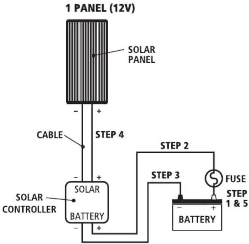
Single Panel, 12V Installation
You will also need:
- Suitable solar controller
-
Suitable cable. (If solar panel is within 3 metres from the battery use 4mm cable, within 6m use 5mm cable and within 9 metres use 6mm. It is not recommended to run longer than 9m.)
• 10A Fuse or circuit breaker. -
Connect a fuse or circuit breaker to the positive terminal of the battery, (As near to the battery as possible) refer to Fig. 4. Leave the fuse out.
- Connect a cable from the fuse or circuit breaker to the solar controllers' positive terminal.
- Connect a cable from the battery's negative terminal to the solar controller's negative terminal.
- Connect the solar panel to the solar controller. Ensure positive to positive and negative to negative.
- Insert fuse.
FIG 4
flowchart
graph TD
    A["1 PANEL (12V)"] --> B["SOLAR PANEL"]
    B --> C["CABLE"]
    C --> D["SOLAR CONTROLLER"]
    D --> E["SOLAR BATTERY"]
    E --> F["BATTERY"]
    F --> G["FUSE STEP 1 & 5"]
    G --> H["STEP 2"]
    H --> I["STEP 3"]
    I --> J["STEP 4"]
CONNECTING MULTIPLE SOLAR PANELS
Additional solar panels can be connected together. Different configurations produce different voltages and currents. For example: Two panels connected in series, will double the voltage. Two panels connected in parallel will double the current.
Note: When connecting multiple solar panels in arrays always use the same type and size!
Blocking & Bypass Diodes – Shading
Where multiple solar panels are used, diodes are necessary to ensure solar panels perform as efficiently as possible. If one of the solar panels is shaded it will begin to discharge (draw power from the system). To overcome this effect, diodes are placed in the circuit. See Fig. 5 & Fig. 6.
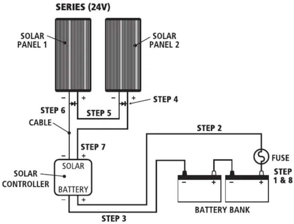
Two Panels in Series 24V Installation
You will also need:
- 24V Solar Controller
-
Suitable cable. (If solar panel is within 3 metres from the battery use 4mm cable, within 6m use 5mm cable and within 9 metres use 6mm. It is not recommended to run longer than 9m.)
• 10A Fuse or circuit breaker -
Connect a fuse or circuit to the positive terminal of the battery bank, (As near to the battery as possible) refer to Fig. 6. Leave the fuse out.
- Connect a cable from the fuse or circuit breaker to the solar controllers' positive terminal.
- Connect a cable from the battery bank's negative terminal to the solar controller's negative terminal.
- Connect a cable from Solar Panel No.1's positive terminal to Solar Panel No.2's negative terminal to create a solar panel array.
- Connect a cable from the solar array's negative terminal to the solar controller's negative terminal.
- Connect a cable from the solar array's positive terminal to the solar controller's positive terminal.
- Insert fuse.
FIG 5
flowchart
graph TD
    A["SOLAR PANEL 1"] -->|+| B["SOLAR PANEL 2"]
    C["SOLAR CONTROLLER"] -->|-| B
    B -->|+| D["BATTERY BANK"]
    D -->|+| E["STEP 3"]
    E --> F["STEP 2"]
    F --> G["FUSE"]
    G --> H["STEP 1 & 8"]
    style A fill:#f9f,stroke:#333
    style B fill:#f9f,stroke:#333
    style C fill:#f9f,stroke:#333
    style D fill:#ccf,stroke:#333
    style E fill:#ccf,stroke:#333
    style F fill:#cfc,stroke:#333
    style G fill:#fcc,stroke:#333
    style H fill:#fcc,stroke:#333
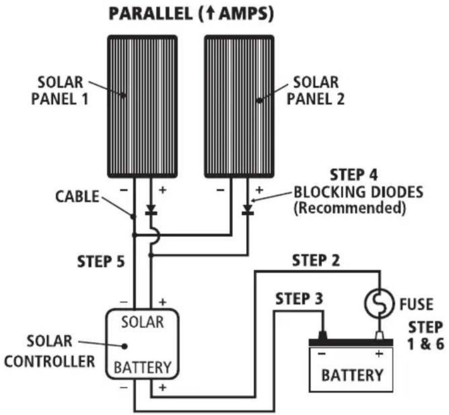
Two Panels in Parallel, 12V Installation
You will also need:
- Suitable solar controller
- Suitable cable (See table 2 for recommended cable sizes)
-
Correct rated fuse or circuit breaker
-
Connect a fuse or circuit breaker to the positive terminal of the battery, (As near to the battery as possible) refer to Fig. 8. Leave the fuse out.
- Connect a cable from the fuse or circuit breaker to the solar controllers' positive terminal.
- Connect a cable from the battery's negative terminal to the solar controller's negative terminal.
- Connect both solar panels to the solar controller. Ensure positive to positive and negative to negative. Refer to Figure 8.
- Insert fuse.
Note: More than two solar panels can be added in parallel by simply repeating steps 4 and 5. Depending on the number of Solar panels added choose a solar controller, fuse and cabling between the battery and solar controller that will handle the increased current.
Table 2 – Recommended Cable Sizes
| Cable distance Solar Panel Solar Panel Solar Panel Solar Panel (meters) SPP80-MC4 SPP120-MC4 SPP135-MC4 SPP150-MC4(Total 160W, (Total 240W, (Total 270W, (Total 300W, 9.16A) 13.72A) 15.44A) 17.16A) | ||||
| 3m | 4mm | 5mm | 5mm | 6mm |
| 6m | 6mm | 8mm^2 or 8 B&S | 8mm^2 or 8 B&S | 8mm^2 or 8 B&S |
| 9m | 8mm^2 or 8 B&S | 8mm^2 or 8 B&S | 8mm^2 or 8 B&S | 8mm^2 or 8 B&S |
FIG 6
flowchart
graph TD
    A["SOLAR PANEL 1"] --> B["CABLE"]
    C["SOLAR PANEL 2"] --> D["STEPS 4 BLOCKING DIODES (Recommended)"]
    B --> E["SOLAR BATTERY"]
    D --> E
    E --> F["SOLAR CONTROLLER"]
    F --> G["FUSE STEP 3"]
    G --> H["BATTERY"]
    H --> I["STEPS 5"]
    I --> J["SOLAR PANEL 1 ↑AMPS"]
    style A fill:#f9f,stroke:#333
    style C fill:#f9f,stroke:#333
    style E fill:#ccf,stroke:#333
    style F fill:#cfc,stroke:#333
    style G fill:#fcc,stroke:#333
    style H fill:#cff,stroke:#333
    style I fill:#ffc,stroke:#333
Four Panels in Series & Parallel, 24V Installation
You will also need:
- 24V Solar Controller
- Suitable cable. (see Table 3 for recommended cable sizes)
-
Correct rated fuse or circuit breaker
-
Connect a fuse or circuit breaker to the positive terminal of the battery, (As near to the battery as possible) refer to Fig. 10. Leave the fuse out.
- Connect a cable from the fuse or circuit breaker to the solar controllers' positive terminal.
- Connect a cable from the battery's negative terminal to the solar controller's negative terminal.
- Connect blocking diode to solar Panel 2 and 4. Be sure to connect the end of the diode with the white band to the extra post and the unmarked end to the positive (+) terminal. Note: The SPP60, SPP80, SPP120 & SPP135 do not have an extra post and will have to be connected directly to the cable. See Fig. 11.
- Connect the cable from Solar Panel No.1's positive terminal to Solar Panel No.2's negative terminal to create a solar panel array.
- Connect the cable from Solar Panel No.3's positive terminal to Solar Panel No.4's negative terminal to create a second solar panel array.
- Connect cables from all of the solar array's negative terminals to the solar controller's negative terminal.
- Connect cables from all of the solar array's positive terminals to the solar controller's positive terminal.
- Insert fuse.
Table 3 – Recommended Cable Sizes
| Cable distance Solar Panel Solar Panel Solar Panel Solar Panel(meters) SPP80-MC4 SPP120-MC4 SPP135-MC4 SPP150-MC4(24V, 9.16A) (24V, 13.72A) (24V, 15.44A) (24V, 17.16A) | ||||
| 3m 4mm 5mm 5mm 6mm | ||||
| 6m 6mm 8mm | ^2 or 8 B&S | 8mm ^2 or 8 B&S | 8mm ^2 or 8 B&S | |
| 9m 8mm | ^2 or 8 B&S | 8mm ^2 or 8 B&S | 8mm ^2 or 8 B&S | 8mm ^2 or 8 B&S |
FIG 7

flowchart
graph TD
    A["SOLAR ARRAY 1"] --> B["SOLAR PANEL 1"]
    B --> C["SOLAR PANEL 2"]
    C --> D["SOLAR PANEL 3"]
    D --> E["SOLAR PANEL 4"]
    E --> F["SOLAR ARRAY 2"]
    F --> G["STEP 4 BYPASS DIODES (Recommended)"]
    G --> H["STEP 5 BLOCKING DIODES (Recommended)"]
    H --> I["STEP 5"]
    I --> J["SOLAR CONTROLLER"]
    J --> K["SOLAR BATTERY"]
    K --> L["BATTERY BANK"]
    L --> M["FUSE"]
    M --> N["STEP 1 & 10"]
    style A fill:#f9f,stroke:#333
    style B fill:#f9f,stroke:#333
    style C fill:#f9f,stroke:#333
    style D fill:#f9f,stroke:#333
    style E fill:#f9f,stroke:#333
    style F fill:#f9f,stroke:#333
    style G fill:#f9f,stroke:#333
    style H fill:#f9f,stroke:#333
    style I fill:#f9f,stroke:#333
    style J fill:#f9f,stroke:#333
    style K fill:#f9f,stroke:#333
    style L fill:#f9f,stroke:#333
    style M fill:#f9f,stroke:#333
    style N fill:#f9f,stroke:#333
MAINTENANCE
Periodically inspect the electrical connections and panel mounting bolts. Make sure they are all tight and free from corrosion. If necessary clean the surface of the solar panels with a soft dump cloth. Mild detergent can also be used. Any dirt or residue on the glass may effect performance.
FREQUENTLY ASKED QUESTIONS
Q. Can the solar panel be mounted on a flat roof or wall?
A. Yes. It is fine to mount the panel on a horizontal surface such as a roof or on a vertical surface like a wall as long as the panel receives full sun for a reasonable period of the day. You will however gain 25% performance if the panel is tilted toward the sun and faced in a northerly direction, since this enables the maximum amount of solar energy to reach the panel.
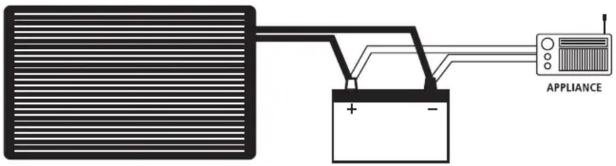
Q. What appliances can I run on the solar panel?
A. Solar panels gain all their energy from the sun and are therefore limited in their ability to operate 12VDC appliances directly. Although they may run very small appliances it is more common to connect the solar panel and appliance to a battery. This method is much more effective, provides a stable voltage and allows the appliance to continue to operate even if the panel is shaded.
Q. Can I run more than one solar panel?
A. It is possible to run multiple solar panels for higher voltage applications or for more power:
-
Placing 2 solar panels in 'Series' will make them suitable for use on 24VDC battery systems or vehicles
-
Placing 2 or more panels in 'Parallel' will still make them suitable for 12VDC use but will provide twice as much power (current). Refer to the section "Connecting Multiple Solar Panels".
Q. Will the solar panel charge my flat battery & how long will it take?
A. The SPP80-MC4, SPP120-MC4, SPP135-MC4 & SPP150-MC4 will charge a battery. See table below for recommended charge times.
Recommended charge times for different solar panels
| SPP80-MC4 SPP120-MC4 SPP135-MC4 SPP150-MC4 | ||||
| Automotive 250–900 CCA 250–1200 CCA 300–1300 CCA 350–1400 CCA | ||||
| Marine 300–1000 MCA 350–1500 MCA 400–2000 MCA 500–2200 MCA | ||||
| Deep Cycle 30–140 Ah 40–200 Ah 50–240 Ah 60–260 Ah | ||||
| Charging times | 7–35 Hours | 7–35 Hours | 7–35 Hours | 7–35 Hours |
Q. I am going on a 4WD trip. How many solar panels will I need?
A. It really comes down to how many appliances are drawing power from your battery.
The number of solar panels required should be based on how much power is used over a 24 hour period.
For example: Most people when they go away would run a Fridge, and a couple of lights to cook with etc.
We need to work out how much power would be used in a day.
Energy consumption per day
| Appliance | Current use/hour (Ah) | Total time of use/day (Hours) | Total Current per day (Amps) |
| Fridge | 1.5 | 24 | 36 |
| Lights | 3 | 3 | 9 |
| Grand total 45 |
So we need to size a solar system that can produce around 45 Amps per day. If we say we get around 10 hours of solar energy from the panels per day (for summer months). We can then calculate what size and how many panels we need.
45 amps ÷ 10 hours = 4.5 Amps per hour
One SPP80 to produce 4.6 Amps an hour should be more than enough. You might find that during cloudy weather you will have to charge the battery by running your car for half an hour every second or third day
NOTES
WARRANTY STATEMENT
APPLICABLE ONLY TO PRODUCT SOLD IN AUSTRALIA
Brown & Watson International Pty Ltd of 1500 Ferntree Gully Road, Knoxfield, Vic., telephone (03) 9730 6000, fax (03) 9730 6050, warrants that all products described in its current catalogue (save and except for all bulbs and lenses whether made of glass or some other substance) will under normal use and service be free of failures in material and workmanship for a period of one (1) year (unless this period has been extended as indicated elsewhere) from the date of the original purchase by the consumer as marked on the invoice. This warranty does not cover ordinary wear and tear, abuse, alteration of products or damage caused by the consumer.
To make a warranty claim the consumer must deliver the product at their cost to the original place of purchase or to any other place which may be nominated by either BWI or the retailer from where the product was bought in order that a warranty assessment may be performed. The consumer must also deliver the original invoice evidencing the date and place of purchase together with an explanation in writing as to the nature of the claim.
In the event that the claim is determined to be for a minor failure of the product then BWI reserves the right to repair or replace it at its discretion. In the event that a major failure is determined the consumer will be entitled to a replacement or a refund as well as compensation for any other reasonably foreseeable loss or damage.
This warranty is in addition to any other rights or remedies that the consumer may have under State or Federal legislation.
IMPORTANT NOTE
Our goods come with guarantees that cannot be excluded under the Australian Consumer Law. You are entitled to a replacement or refund for a major failure and compensation for any other reasonably foreseeable loss or damage. You are also entitled to have the goods repaired or replaced if the goods fail to be of acceptable quality and the failure does not amount to a major failure.
Distributed by
AUSTRALIA
Brown & Watson International Pty Ltd
Knoxfield, Victoria 3180
Telephone (03) 9730 6000
Facsimile (03) 9730 6050
National Toll Free 1800 113 443
NEW ZEALAND
Narva New Zealand Ltd
22–24 Olive Road
PO Box 12556 Penrose
Auckland, New Zealand
Telephone (09) 525 4575
Facsimile (09) 579 1192