Vision 8AS - Tripod Vinten - Free user manual and instructions
Find the device manual for free Vision 8AS Vinten in PDF.

| Product Type | Tripod |
| Brand | Vinten |
| Model | Vision 8AS |
| Category | Professional Tripod System |
| Material | Aluminum alloy with carbon fiber legs (optional) |
| Maximum Load Capacity | 8 kg (17.6 lbs) |
| Weight (Tripod only) | 3.2 kg (7.1 lbs) |
| Height Range | 40 cm to 160 cm (15.7 in to 63 in) |
| Leg Sections | 3 sections |
| Lock Type | Quick-release lever locks |
| Leveling Bubble | Integrated bubble level |
| Fluid Head Type | Vision 8AS fluid head with variable counterbalance |
| Pan Range | 360 degrees |
| Tilt Range | +90° / -75° |
| Spreader Type | Mid-level spreader (included) |
| Warranty | 3 years (parts and labor) |
| Cleaning Instructions | Wipe with a dry cloth; avoid solvents |
| Storage Recommendations | Store in a dry place at room temperature |
| Safety Warnings | Do not exceed maximum load; secure all locks before use |
| Repair Parts Availability | Contact Vinten authorized service centers |
| Country of Origin | United Kingdom |
| Dimensions (Folded) | 80 cm (31.5 in) |
| Accessories Included | Fluid head, spreader, panhandle, carry bag |
Frequently Asked Questions - Vision 8AS Vinten
User questions about Vision 8AS Vinten
0 question about this device. Answer the ones you know or ask your own.
Ask a new question about this device
Download the instructions for your Tripod in PDF format for free! Find your manual Vision 8AS - Vinten and take your electronic device back in hand. On this page are published all the documents necessary for the use of your device. Vision 8AS by Vinten.
USER MANUAL Vision 8AS Vinten
Vision AS Pan & Tilt Heads
V4043-0001
V4044-0001
V4045-0001
V4046-0001
Operating instructions
V4045-4984/4
EN
JP
Serial No. 1500 onwards
Publication No. V4045-4984 Issue 4
English ...... page 5
日本語 ……ページ 29
Copyright © Vitec Group plc.
All rights reserved throughout the world. No part of this document may be stored in a retrieval system, transmitted, copied or reproduced in any way including, but not limited to, photocopy, photograph, magnetic or other record without the prior agreement and permission in writing of Vitec Group plc.
Trademarks
Vinten® and Vision® are registered trademarks of Vitec Group plc.
Important information about this document
Information contained within this document is subject to change. Vitec Videocom Limited reserves the right, without notice to make changes in equipment design or performance as progress in engineering, manufacturing or technology may warrant.
Published by
Vitec Group Videocom division Technical Publications Department William Vinten Building Western Way Bury St Edmunds Suffolk IP33 3TB UK Email: technical.publications@vitecgroup.com
Understanding these instructions
English

The original instructions presented in this operators guide were written in English, and subsequently translated into other languages. If you are unable to understand these instructions, contact Vinten or your distributor to obtain a translation of the original instructions (EU Countries).
БЪЛГАРСКИ

Safety - read this first. 6
Usage....6
Caring for the environment by recycling 6
Technical specification ....7
Introduction and description.... 11
Balance 11
Pan and tilt drag....11
Pan and tilt brakes....11
Illuminated level bubble 11
Camera mounting 11
Pan bar 12
Operation 13
Fitting the pan bar 13
Mounting the camera using 3/8 in. camera mounting screws ..... 14
Checking camera balance 18
Applying the pan and tilt brakes. 22
Applying pan and tilt drag 22
Maintenance....24
General 24
Cleaning....24
Routine maintenance....24
Battery replacement....24
Adjusting the pan and tilt brakes 25
Parts list 27
Safety - read this first
Warning Symbols in this Operators Guide

Where there is a risk of personal injury or injury to others, comments appear highlighted by the word WARNING!—supported by the warning triangle symbol.
Where there is a risk of damage to the product, associated equipment, process or surroundings, comments appear highlighted by the word CAUTION!
Usage
The Vision AS range of pan and tilt heads are designed for use by professional camera operators and are ideally suited for electronic news gathering and video production. These lightweight heads can support and balance a camera and ancillary equipment weighing up to 17.0 kg (37.5 lb). It is important that the head is mounted onto equipment designed to support the head and its maximum payload.

Warning!
- Do NOT attempt to use this product if you do not understand how to operate it.
- Do NOT use this product for any other purpose than that specified in this Usage statement.
- Maintenance beyond that detailed in this Operators Guide must be performed only by competent personnel in accordance with the procedures specified in the Maintenance Manual.
Caring for the environment by recycling
Disposal of waste batteries
Any batteries included with this product must not be treated as household waste. By ensuring these batteries are disposed of correctly, you will help prevent potentially negative consequences for the environment and human health, and help conserve natural resources. Please view the section on how to remove the battery from the product safely. Hand the battery over to the applicable collection point for recycling waste batteries.
Technical specification
Vision 3AS pan and tilt head
Height 15.1 cm (5.9 in.)
Length 13.8 cm (5.4 in.)
Width 13.8 cm (5.4 in.)
Weight including pan bar and bowl clamp assembly 2.8 kg (6.2 lb)
Tilt range. ±90°
Pan range 360°
Levelling bubble ..... illuminated
Typical Payload 3.5 kg (7.72 lb)
Mounting interface 75 mm ball base
Pan bar.....single universal fixed length
Vision 5AS pan and tilt head
Height....15.1 cm (5.9 in.)
Length 13.8 cm (5.4 in.)
Width 13.8 cm (5.4 in.)
Weight including pan bar and bowl clamp assembly 2.8 kg (6.2 lb)
Tilt range. ±90^
Pan range 360°
Levelling bubble ..... illuminated
Typical Payload 7.0 kg (15.4 lb)
Mounting interface 75 mm ball base
Pan bar.....single universal fixed length
Vision 8AS pan and tilt head
Height 16 cm (6.3 in.)
Length 15.1 cm (5.9 in.)
Width 13.8 cm (5.4 in.)
Weight including pan bar and bowl clamp assembly 3.1 kg (6.8 lb)
Tilt range. ±90^
Pan range 360°
Levelling bubble ..... illuminated
Typical payload.... 11 kg (24.3 lb)
Mounting interface 100 mm ball base
Pan bar.....single universal fixed length
Vision 10AS pan and tilt head
Height.... 16 cm (6.3 in.)
Length 15.1 cm (5.9 in.)
Width 13.8 cm (5.4 in.)
Weight including pan bar and bowl clamp assembly . . . . . . . . . . . . . . . . . . . . . . . . . . . . . . . . . . . . . . . . . . . . . . . . . . . . . . . . . 3.2 kg (7.0 lb)
Tilt range. ±90^
Pan range 360°
Levelling bubble ..... illuminated
Typical payload....13.0 kg (28.7 lb)
Mounting interface 100 mm ball base
Pan bar.....single universal telescopic
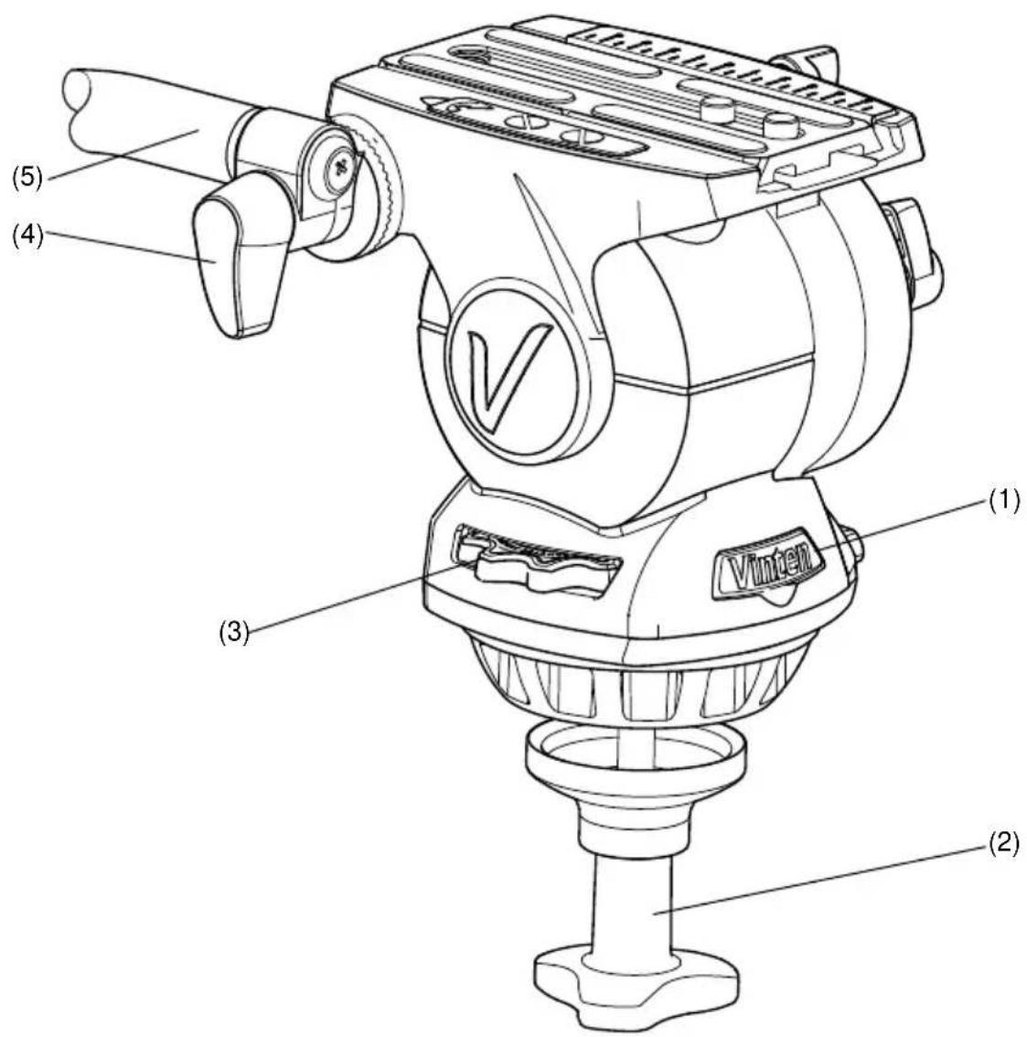
Fig. 1 Vision AS pan and tilt head (front and right-hand side)
(1) Battery compartment
(2)......Bowl clamp assembly
(3) Perfect balance control
(4) Pan bar clamp
(5)....Pan bar
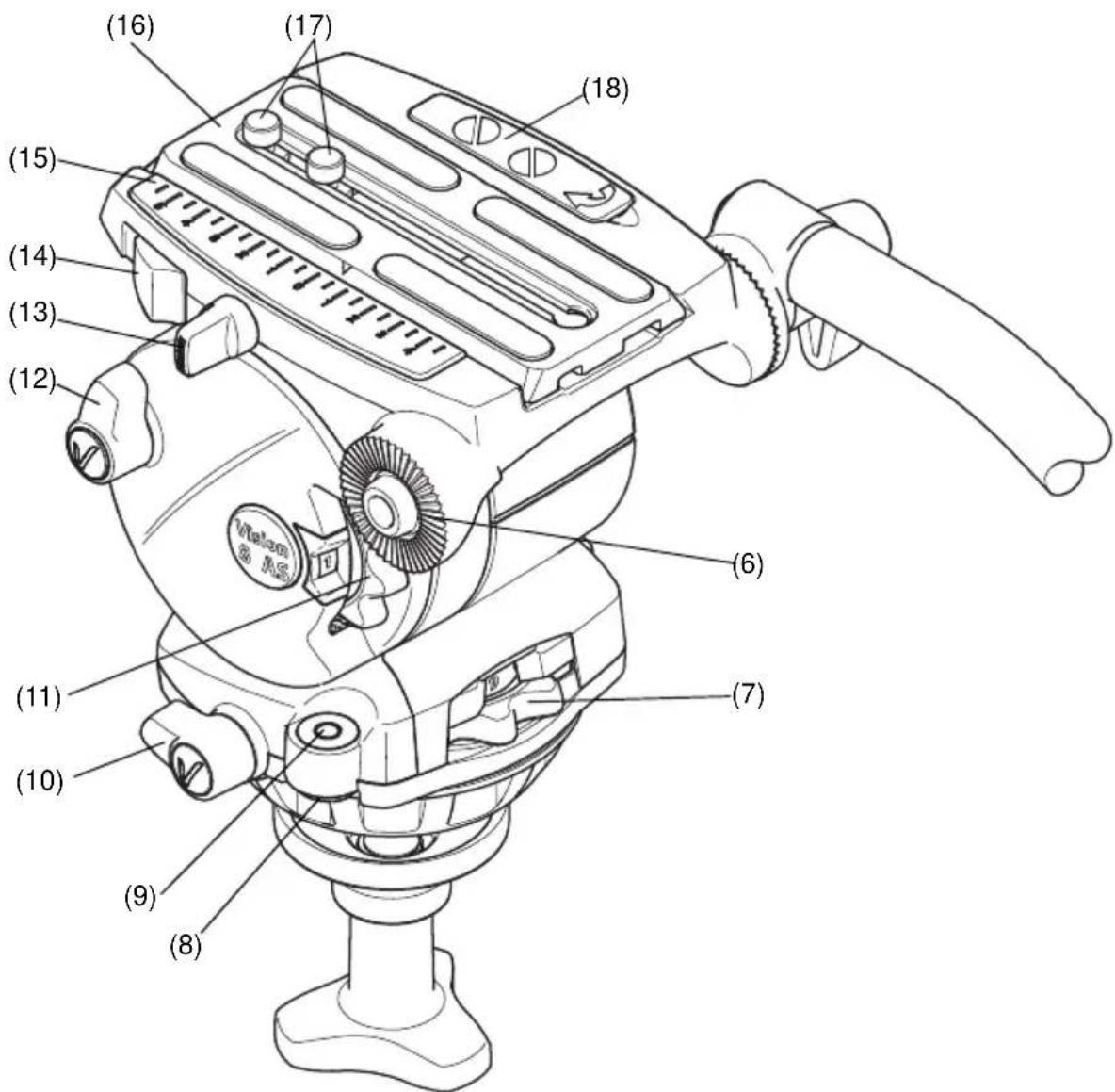
Fig 2 Vision AS pan and tilt head (left-hand side)
(6)....Pan bar mounting
(7)....Pan drag control
(8) Switch for illuminating the level bubble
(9)Level bubble
(10) Pan brake lever
(11)....Tilt drag control
(12) Tilt brake lever
(13) ...... Slide plate clamp
(14)....Slide load release
(15) ...... Slide plate scale
(16) Slide plate (side-loading)
(17)....3/8 in. camera mounting screws
(18).Camera screw storage compartment
Introduction and description
The Vision 3AS, 5AS, 8AS and 10AS pan and tilt heads have been designed to support and perfectly balance a range of professional digital video cameras. The Vision AS pan and tilt head is equipped with a quick release side-loading camera plate that allows operators to easily and quickly setup and remove the camera. Levelling the head is achieved using the level bubble that can be illuminated when setting up at locations with low lighting levels. The placement of the pan and tilt brakes, drag controls and counter balance allows the operator to easily adjust the settings whilst operating the camera.
Balance
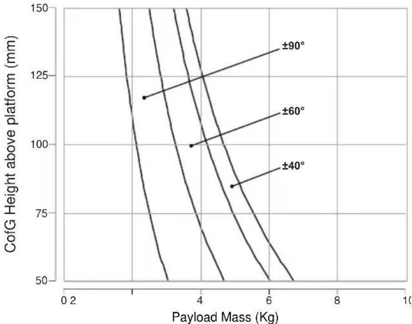
The AS head provides infinitely adjustable balance, allowing operators to adjust the amount of counter balance required using the Perfect Balance control (3) located on the right-hand-side of the head. Maximum and minimum payloads that can be balanced are dependent on the weight of the camera and accessories fitted, and on the centre of gravity (C of G) height. The balance graphs (Fig. 8 to Fig. 11) illustrate the range of load and C of G height that can be maintained in balance.
Pan and tilt drag
Both pan and tilt mechanisms incorporate the patented Vinten lubricated friction (LF) system to ensure smooth movement of the camera about these axes. The pan and tilt drag is adjusted using the pan drag control (7) and tilt drag control (11).
Pan and tilt brakes
Both pan and tilt brakes allow each axis on the head to be locked at any chosen position. The pan brake lever (10) and tilt brake lever (12) are located on the left-hand side of the head.
Illuminated level bubble
An illuminated level bubble (9) is located to the rear of the head on the left-hand side. In situations of low light, the level bubble can be illuminated by pressing the switch (8) located underneath the level bubble. The level bubble will be illuminated for approximately 20 seconds. If longer illumination is required (approximately 40 seconds), press and hold the button until it flashes once. Pressing the button a second time will switch the illumination off.
The battery for the illuminated level bubble is located in the battery compartment at the front of the head (1) behind the Vinten label. If the battery level is low, the level bubble illumination will flash 3 times when switched on.
Camera mounting
The camera is attached to the head using the new side-loading slide plate (16), which allows the camera to be rapidly setup and removed. The side-loading slide plate (16) is attached to the camera and then loaded from above into a side-loading clamp mechanism and secured in
English
position by the slide plate clamp (13). The slide load release (14) allows rapid removal of the slide plate (16) from the head by lifting the camera upwards.
The head is supplied with a 1/4 in. screw and pin adaptor to suit most lightweight camcorders and two 3/8 in. camera mounting screws. When not in use, the 1/4 in. screw and pin adaptor, and 3/8 in. camera mounting screws can be stored in the camera screw storage compartment (18) located on the left-hand side of the camera mounting platform.
Pan bar
Pan bar mounting points (6) are located at the rear of the head on either side of the camera mounting platform. The pan bar (5) is attached using a pan bar clamp (4), with angular adjustment available on the mount serrations. A fixed pan bar is supplied with the Vision 3AS, 5AS and 8AS heads. A telescopic pan bar is supplied with the Vision 10AS head. A second pan bar may be fitted on the other side of the head if required.
Field service spares kit
A field service spares kit (V4045-1902), that includes brake levers and a spare battery, is supplied with all Vision AS pan and tilt heads. See the spares part listing on page 28 for more information.
Operation
Fitting the pan bar
A single pan bar is supplied and is fitted to either the right or left-hand side of the head onto the pan bar mounting (6).
To fit the pan bar:
Position the pan bar (5) onto the pan bar mounting (6).
Rotate the pan bar clamp (4) in a clockwise direction until the pan bar is secured.
A second pan bar can be fitted to the other side of the head if required.
Installing the head onto a tripod
The Vision 3AS and 5AS pan and tilt heads are supplied with an integral 75 mm ball mount and the Vision 8As and 10AS heads have an integral 100 mm ball mount, designed for installation on a compatible Vinten tripod. Adaptors are available to allow the head to be installed onto tripods or pedestals fitted with other mountings.
To install the head onto the tripod:
Remove the bowl clamp assembly (2) from the head by turning the assembly in a counter-clockwise direction.
Position the head on the tripod, carefully lowering the head into the tripod bowl.
Using the pan bar to steady the head, refit the bowl clamp assembly (2) from below the tripod bowl, turning the bowl clamp assembly (2) in an clockwise direction until the head is held in position.
Apply the pan brake (10) and tilt brake (12) by turning the levers in a clockwise direction.
CAUTION! DO NOT use force on the brake levers. Hand tighten only.
Level the head using the level bubble (8) and once level, tighten the bowl clamp assembly (2) to secure the head in position. When attempting to level the head in situations where there is low light, the level bubble can be illuminated by pressing the switch (8) located underneath the level bubble (9). The light will extinguish after approximately 20 seconds.
Mounting the camera using 3/8 in. camera mounting screws
The camera slide plate (16) is secured to the base of the camera using either two 3/8 in. camera screws or a 1/4 in. screw pin adaptor (also see Mounting the camera using the 1/4 in. screw and pin adaptor on page 16).
To mount the camera onto the head:
Remove the camera slide plate (16) from the head (Fig. 3). Turn the slide plate clamp (13) approximately 1/2 a turn in a counter-clockwise direction to release the clamp. Then push the slide lock release (14) in a forwards direction to release and eject the slide plate (16). When released, the camera slide plate (16) can be lifted upwards and removed from the head.
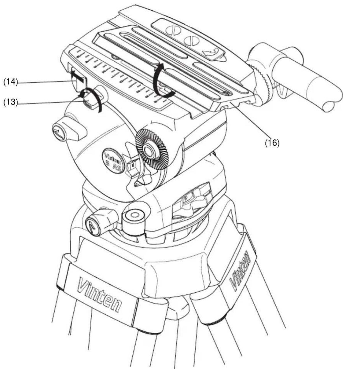
Fig. 3 Removing the camera slide plate
Position the two 3/8 in. camera screws (17) as far apart as possible on the camera slide plate (16) (Fig. 4).
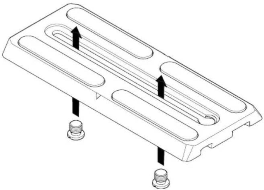
natural_image
Technical line drawing of a mechanical component with three slots and two threaded fasteners (no text or symbols)Fig. 4 Fitting the 3/8 in. camera mounting screws
Attach the camera slide plate (16) to the camera or camera mounting plate approximately under the centre of the camera's weight.
If not already done, apply both the pan brake (10) and tilt brake (12) by turning the levers in a clockwise direction.
CAUTION! DO NOT use force on the brake levers. Hand tighten only.
Lower the camera onto the camera mounting platform (Fig. 5) ensuring that the edge of the camera slide plate (16) opposite the slide clamp (13) engages first, and then push downward until the slide clamp ‘snaps’ into position.
Using the pan bar (5) to steady the camera, tighten the slide plate clamp (13) in a clockwise direction to secure the camera in position.
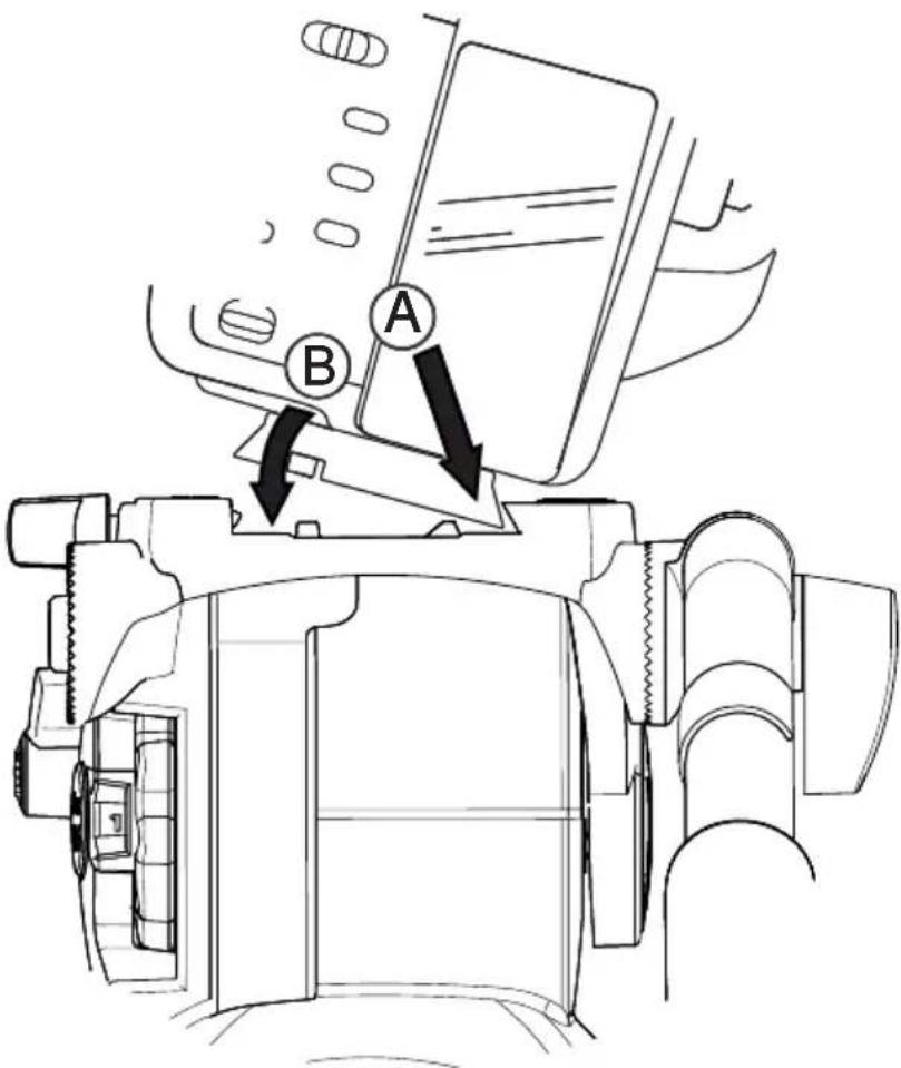
Fig. 5 Mounting the camera onto the head
Mounting the camera using the 1/4 in. screw and pin adaptor
A 1/4 in. screw and pin adaptor, comprising a 1/4 in. locating pin on a plate and a 1/4 in. camera mounting screw, is stored in the camera storage compartment (18) on right-hand side of the camera mounting platform.
To mount the camera onto the head:
Remove the camera slide plate (16) from the head (Fig. 3). Turn the slide plate clamp (13) approximately 1/2 a turn in a counter-clockwise direction to release the clamp. Then push the slide lock release (14) in a forwards direction to release and eject the slide plate (16). When released, the camera slide plate (16) can be lifted upwards and removed from the head.
Open the camera storage compartment (18) by lifting the cover upwards and remove the 1/4 in. screw and pin adaptor (19) (Fig. 6).
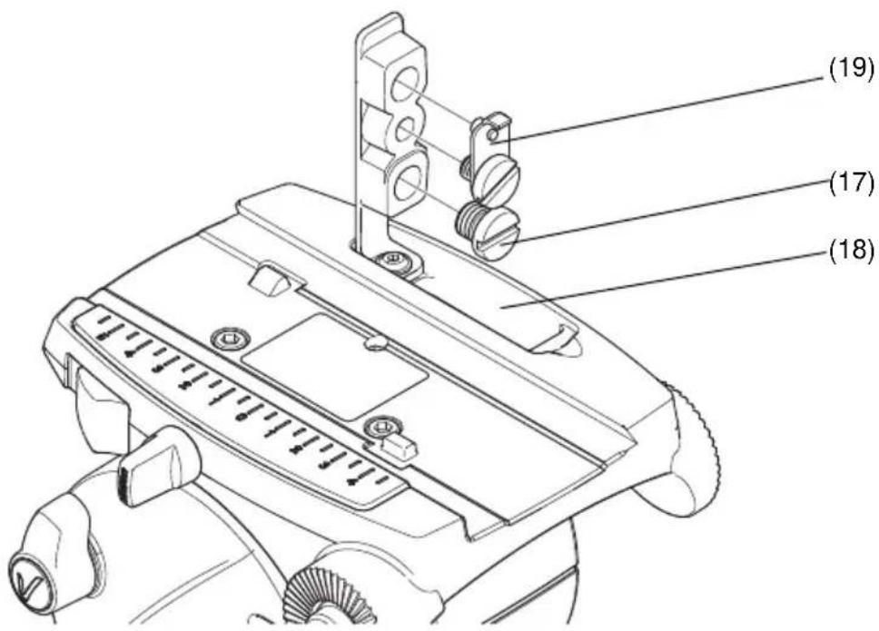
Fig. 6 Camera screw storage compartment
Remove the 3/8 in. camera mounting screws (17) from the camera slide plate (16) (if not already done) and place them into the camera storage compartment (18). Secure the compartment cover by pressing the cover downwards.
Mount the 1/4 in. screw and pin adaptor (19) onto the top of the camera slide plate (16) with the 1/4 in. camera mounting screw from under the slide plate (Fig. 7).
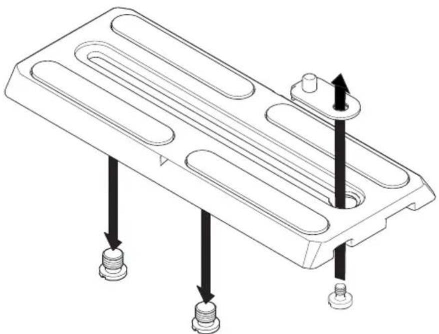
natural_image
Technical line drawing of a mechanical component with three threaded fasteners and mounting holes (no text or symbols)Fig. 7 Fitting the 1/4 in. pin adaptor assembly
English
Attach the camera slide plate (16) to the camera or camera mounting plate approximately under the centre of the camera's weight.
If not already done, apply both pan brake (10) and tilt brake (12) by turning the levers in a clockwise direction.
CAUTION! DO NOT use force on the brake levers. Hand tighten only.
Lower the camera onto the camera mounting platform (Fig. 5) ensuring that the edge of the camera slide plate (16) opposite the slide clamp (13) engages first, and then push downward until the slide clamp 'snaps' into position.
Using the pan bar (5) to steady the camera, tighten the slide plate clamp (13) in a clockwise direction to secure the camera in position.
Checking camera balance
A perfectly balanced head allows operators to control camera movement with the minimal amount of effort. Once balanced, the head and its payload can be set to any tilt position and remain at that position, allowing operators work hands-free.
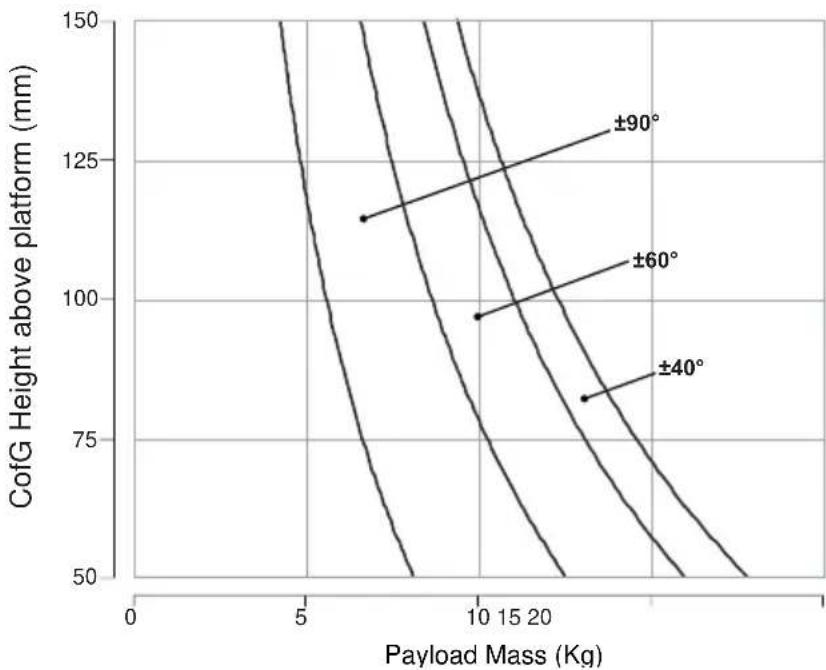
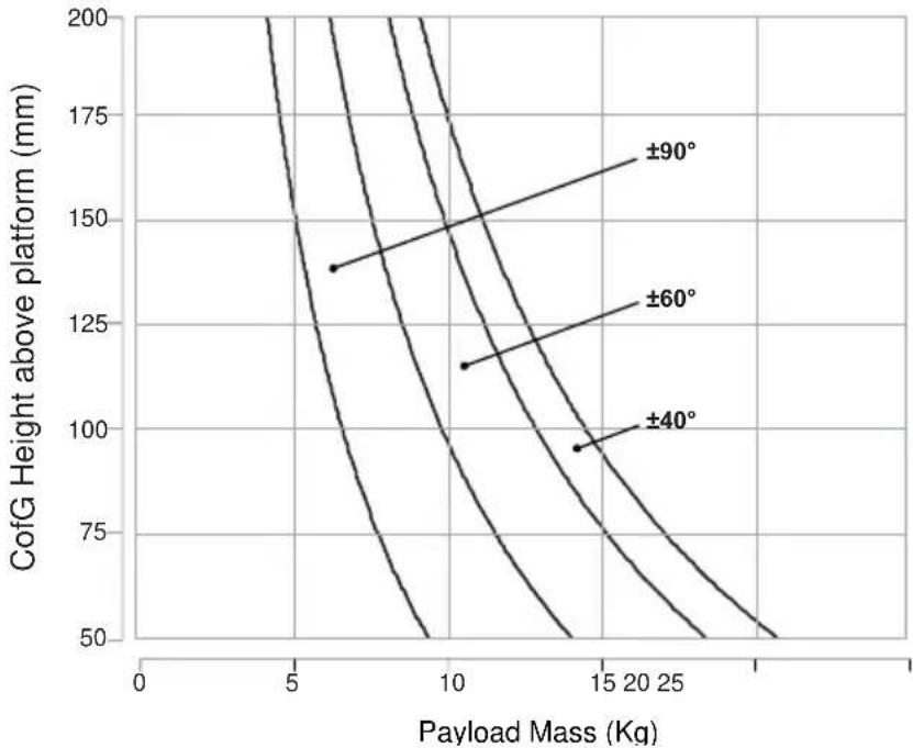
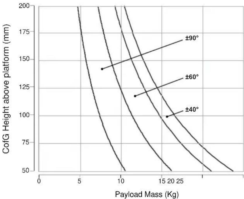
Balance graphs (Fig. 8 to Fig. 11) illustrate the relationship between load and Centre of Gravity (C of G) height for each Vision AS pan and tilt head. The balance graphs can be used to ascertain the suitability of the head for any given combination of camera, lens and accessories. The shaded area of graph corresponds to those load/C of G combinations that can be balanced over the full tilt range. The areas to the right indicate the progressively reducing tilt range with greater load and higher C of G. Where a load/C of G combination falls outside of the graph it will be necessary to increase or decrease the weight or the C of G height to enable the head to balance the load.
Before balancing the head, ensure that the camera and lens, pan bar(s) and all ancillary equipment has been fitted. The head must be balanced whenever the camera and/or lens is changed, or when ancillary equipment is added or removed.
line
| Payload Mass (Kg) | CofG Height above platform (mm) | Offset (°) | | ----------------- | -------------------------------- | ---------- | | ~3.5 | ~115 | ±90 | | ~4.0 | ~100 | ±60 | | ~5.0 | ~85 | ±40 |Fig. 8 Vision 3AS balance graph
line
| Payload Mass (Kg) | CofG Height above platform (mm) | | ----------------- | ------------------------------- | | 10 | 115 | | 15 | 95 | | 20 | 80 |Fig. 9 Vision 5AS balance graph
line
| Payload Mass (Kg) | CofG Height above platform (mm) | | ----------------- | ------------------------------- | | 6 | 138 | | 10 | 115 | | 14 | 95 |Fig. 10 Vision 8AS balance graph
line
| Payload Mass (Kg) | CofG Height above platform (mm) | | ----------------- | ------------------------------- | | 8 | 140 | | 12 | 115 | | 20 | 100 |Fig. 11 Vision 10AS balance graph

Warning!
- Do NOT exceed the maximum capacity of either the head or the tripod. The system will become unstable and may fail.
- Always support the camera payload when disengaging the counterbalance (Perfect Balance control) mechanism to prevent it falling away suddenly.
- Keep hands clear of the moving platform to avoid trapping fingers.
To check camera balance:
Reduce tilt drag to a minimum level by turning the tilt adjustment control (11) in an counter-clockwise direction.
Reduce the counter-balance a minimum level by turning the perfect balance control (3) in a clockwise direction.

Warning!
Steady the camera payload using the pan bar. Be prepared to prevent the head falling away suddenly.
Whilst holding the pan bar firmly, release the tilt brake (12) by turning the lever in a counter-clockwise direction.
Tilt the head backwards and forwards to determine if the camera position is equally balanced in both directions. The camera and payload must be positioned over the centre of gravity (Fig. 12).
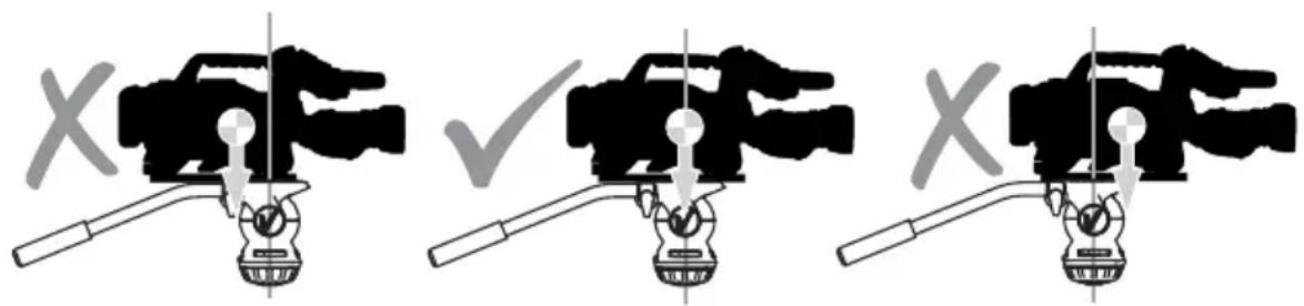
Fig. 12 Positioning the camera over the Centre of Gravity
If the camera is not positioned over the centre of gravity, set the platform level and apply the tilt brake (12). Position the camera correctly on the head by releasing the slide plate clamp (13) and then sliding the camera (on the camera slide plate) backwards or forwards until it balances horizontally. Tighten the slide plate clamp (13) to secure the camera in position. Re-check and adjust as necessary.

Warning!
Securely apply the slide plate clamp (13) when the camera is positioned, to prevent the camera payload slipping.
English
Using the pan bar (5), tilt the head backwards and forwards. Turn the Perfect Balance control (3) clockwise until the camera remains in position and does not fall away when the head is tilted and then released (hands-free).
Repeat the setup until perfect balance is achieved, when the camera remains set at any angle from +90^ to -90^ without falling away or springing back.
NOTE: Maximum tilt angle is less than 90^ for heavy payloads with a high C of G - refer to the balance graphs (Fig. 8 to Fig. 11).
Apply the tilt brake (12) when balance is achieved to prevent the camera from moving accidentally when not in use.
Applying the pan and tilt brakes
Brakes on each axis allow the head to be locked at any chosen position. The pan brake (10) and tilt brake (12) are fitted at the left-hand side of the head.
CAUTION! DO NOT use the brakes to supplement drag, the head may be damaged. When the brakes are not in use, always ensure they are fully released.
To apply the brake:
Turn the brake lever fully clockwise.
CAUTION! DO NOT use force on the brake levers. Hand tighten only.
To release the brake:
Turn the brake lever fully counter-clockwise
Applying pan and tilt drag
Both the pan and tilt mechanisms incorporate a fluid drag system to ensure smooth movement of the camera about these axes. The tilt drag control (11) is located on the left-hand side of the head and the pan drag control (7) is located at the back of the head, beneath the camera mounting platform (Fig. 13).
NOTE: The whip-pan facility is not affected by the pan drag setting.
CAUTION! Reduce drag to a minimum when the head is out of use for long periods, to minimize wear on drag components.
To increase tilt drag:
Turn the tilt drag control (11) in a clockwise direction (downward).
To decrease tilt drag:
Turn the tilt drag control (11) in a counter-clockwise direction (upward).
To increase pan drag:
Turn the pan drag control (7) in a counter-clockwise direction (left to right).
To decrease pan drag:
Turn the pan drag control (7) in a clockwise direction (right to left).
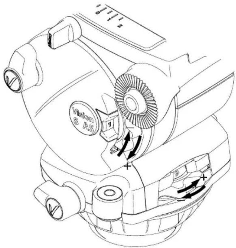
Fig. 13 Adjusting the pan and tilt drag
Maintenance
General
Vinten products are robustly made to high engineering standards and little attention is required to maintain serviceability save regular cleaning. Attention to the following points will ensure a long and useful service life with minimum need for repair.
Cleaning
During indoor use, the only cleaning required should be a regular wipe over with a lint-free cloth. Dirt accumulated during storage may be removed using a semi-stiff brush. Particular attention should be paid to the ball mounting face of the head, the space between the tilting assembly and the base and the mounting bowl of the tripod.
Use out-of-doors under adverse conditions will require special attention. Salt spray should be washed off with fresh water at the earliest opportunity. Sand and dirt acts as an abrasive and should be removed using a semi-stiff brush or vacuum cleaner.
CAUTION! DO NOT use solvent or oil-based cleaners, abrasives or wire brushes to remove accumulations of dirt, as these damage the protective surfaces. Use only detergent-based cleaners.
Routine maintenance
During use, check the following:
Check the illumination of the level bubble. Replace battery if necessary.
Check the effectiveness of the pan and tilt drag controls. Reset as necessary.
Check the effectiveness of the pan and tilt brakes. Reset as necessary.
No further routine maintenance is required.
Battery replacement
The battery used to illuminate the level bubble should be replaced yearly or whenever the illumination is considered inadequate. A replacement battery is included in the field service spares kit.
To replace the battery:
Using a thin-bladed precision screwdriver or similar tool, carefully prise open the battery compartment (1).
Pull out the battery compartment (1) from the head.
Remove the battery (1.1).
Position the new battery (positive terminal upward) in the battery compartment (1), ensuring that it is neatly stowed in the cut-out provided.
CAUTION! Use plastic tweezers when handling the battery. Avoid shortening the battery by holding it by the circumference edge.
Refit the battery compartment (1) into the head.
CAUTION! DO NOT use force on the battery compartment. Ensure that the compartment is correctly aligned with the fittings inside the head.
Press the switch (8) and ensure that the level bubble (9) illuminates for approximately 20 seconds.
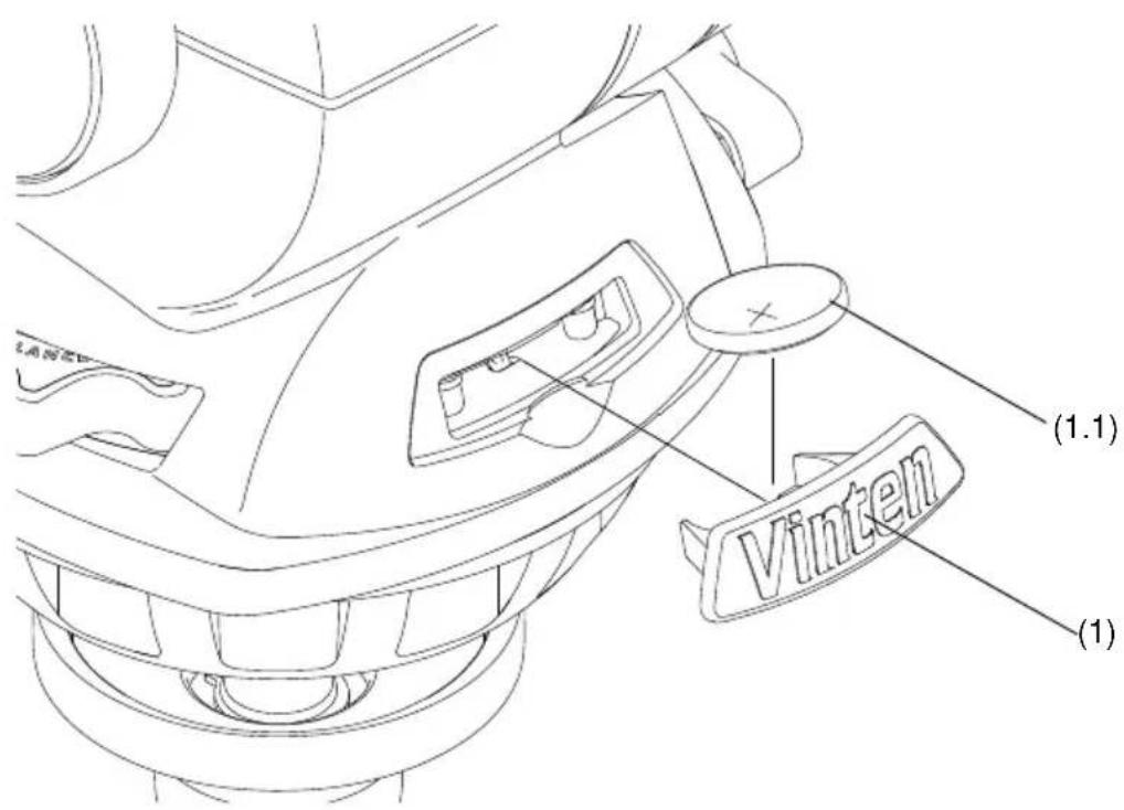
Fig. 14 Replacing the level bubble battery
Adjusting the pan and tilt brakes
The pan and tilt brakes may require adjustment after prolonged use. These adjustments should be carried out by competent persons only. The field service spares kit includes replacement brake levers and caps (if required).
To adjust the brakes:
Turn the brake lever counter-clockwise to its lowest off position as shown in Fig. 15.
Insert the thin-blade of a precision screwdriver or similar tool into the top of the cap (10.1 & 12.1). Carefully prise off the cap. Note that the cap is secured using a small adhesive pad and therefore may require a small amount of force to remove.
Using a 2.5mm allen key, remove the screw (10.2 & 12.2) securing the brake lever.
Remove the brake lever without moving the brake shaft.
Turn the brake shaft clockwise until the brake makes contact.
Replace the brake lever onto the brake shaft at approximately 30-45 degrees from the off position (Fig. 15).
Refit the screw (10.2 & 12.2) using the allen key.
Turn the lever clockwise and ensure that the brake is fully applied before the end stop is reached.
Turn the lever fully counter-clockwise and ensure that the brake is fully released before the end stop is reached.
Re-adjust the position of the lever as necessary.
Ensure that the brake is set to the off position and replace the cap (10.1 & 12.1). Ensure that the cap is positioned with the cut-out at the top and the 'V' in a vertical position.
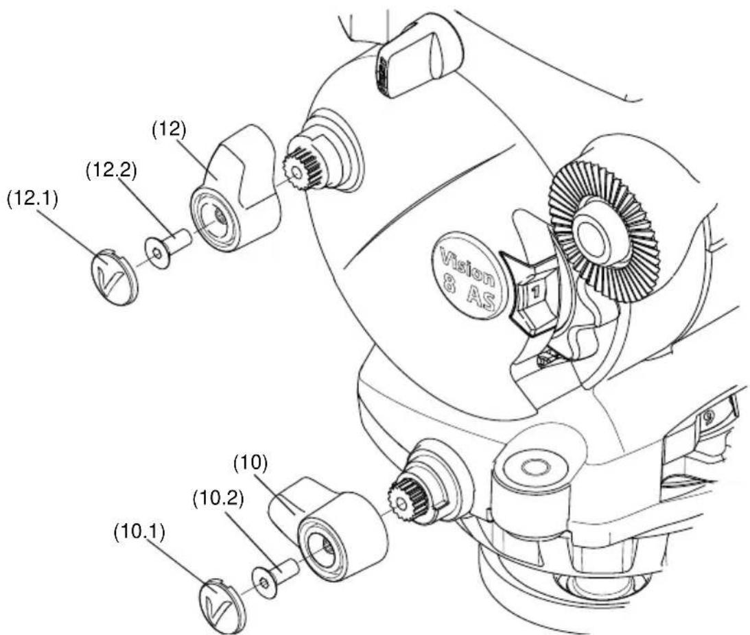
Fig. 15 Adjusting the pan and tilt brakes
Parts list
The following parts lists include main assemblies, user-replaceable spare parts and field service spares kit. The Vision range can be purchased as a complete system including tripod, spreader and soft case if required. For further information regarding the complete systems and spare parts, please contact Vinten or your local Vinten distributor.
For information on-line, visit our website at
www.vinten.com
Vision AS range of pan and tilt heads
Vision 3AS (75 mm bowl)....V4043-0001
Vision 5AS (75 mm bowl)....V4044-0001
Vision 8 AS (100 mm bowl) V4045-0001
Vision 10 AS (100 mm bowl) V4046-0001
Pan bars
Telescopic pan bar (Vision 10AS)....3219-91
Fixed pan bar (Vision 3AS & Vision 5AS).... 3219-110
Fixed pan bar (Vision 8AS)....3219-101
Tripods
Single stage aluminium Pozi Loc tripod, 100 mm bowl, black, ENG ..... V3823-0001
Single stage aluminium Pozi Loc tripod, 75 mm bowl, black, ENG . . . . . . . . . . . V3822-0001
Single stage carbon fibre Pozi-Loc tripod, 100 mm bowl, black, ENG .... 3773-3
Single stage carbon fibre Pozi-Loc tripod, 75 mm bowl, black, ENG .... 3777-3
Two stage aluminium Pozi Loc tripod, 100 mm bowl, black, ENG .... 3821-3
Two stage aluminium Pozi Loc tripod, 75 mm bowl, black, ENG .... 3819-3
Two stage carbon fibre Pozi-Loc tripod, 100 mm bowl, black, ENG 3772-3
Two stage carbon fibre Pozi-Loc tripod, 75 mm bowl, black, ENG 3776-3
Spreaders
Floor spreader 3363-3
Spread-Loc mid-level spreader including carpet feet 3781-3
Soft Cases
Single stage tripod case.... 3334-3
Two stage tripod case 3358-3
English
Optional Accessories
Telescopic pan bar (Vision 3AS and Vision 5AS). 3219-113
Telescopic pan bar (Vision 8AS)....3219-91
Fixed pan bar (Vision 10AS).... 3219-101
User-replaceable spare parts
Camera slide plate (side-loading)....V4045-1008
3/8 in. camera screw (AS range only) V4045-2074
1/4 in. screw and pin adaptor....V4045-1006
Battery tray moulding (8AS & 10AS) V4045-1904
Battery tray moulding (3AS & 5AS) V4043-1904
Bowl clamp assembly 3330-30
Field service spares kit
Field service spares kit....V4045-1902
仕様
ページ
natural_image
Technical line drawing of a mechanical component with three slots and two threaded fasteners (no text or symbols)Fig. 4 カメラ固定ねじを装着する
Fig. 6 カメラの収納部
natural_image
Technical line drawing of a mechanical component with three threaded fasteners and mounting holes (no text or symbols)Operating instructions
V4045-4984/4
Information contained in this document is subject to change.
Vitec Videocom Ltd reserves the right, without notice, to
make changes in equipment design or performance as
progress in engineering, manufacturing or technology may warrant.
本書の情報は変更される場合があります。