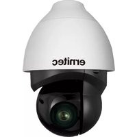
ORION DX 822IR - Security Camera Ernitec - Free user manual and instructions
Find the device manual for free ORION DX 822IR Ernitec in PDF.


| Product Type | Network IR PTZ Security Camera |
| Model | ORION DX 822IR |
| Brand | Ernitec |
| Image Sensor | Sony Progressive Scan CMOS Sensor (2M/3M/4M resolution options) |
| Optical Zoom | Up to 30x |
| Digital Zoom | 10x |
| High Dynamic Range | 120 dB |
| Video Compression | Quad Codec: H.264 Baseline / Main / High Profile + MJPEG |
| Day/Night Function | True Day & Night (ICR) |
| Noise Reduction | 2D/3D Noise Reduction |
| IR Distance | Up to 200 m (adjustable by zoom ratio) |
| Power Input | DC 12V, AC 24V, or PoE+ (IEEE 802.3at 4-Pair 60W) |
| Power Switching | Zero Downtime Power Switching (ZDT) between DC and PoE+ |
| Servo Feedback | Yes, for precise positioning |
| Weatherproof Rating | IP66 (International standard) |
| Network Interface | RJ-45 (10/100/1000Base-T) |
| Audio I/O | 1 Audio In, 1 Audio Out (terminal block) |
| Alarm I/O | 4 Alarm In, 2 Alarm Out (terminal block) |
| RS-485 | Yes (terminal block) |
| SD Card Slot | Yes (for local storage) |
| Dimensions (W x H x D) | Approx. 250 x 300 x 200 mm (estimated from typical PTZ) |
| Weight | Approx. 2.5 kg (estimated) |
| Operating Temperature | Indoor use only (not specified, typical range -10°C to 50°C) |
| Regulatory Compliance | FCC Part 15, RoHS, WEEE |
| Cleaning | Shut down system, unplug, use damp cloth only; no liquid or aerosol cleaners |
| Package Contents | Camera, M4 security screw with rubber, quick guide, CD, 3-pin power terminal block, 14-pin alarm/audio I/O terminal block |
Frequently Asked Questions - ORION DX 822IR Ernitec
User questions about ORION DX 822IR Ernitec
0 question about this device. Answer the ones you know or ask your own.
Ask a new question about this device
Download the instructions for your Security Camera in PDF format for free! Find your manual ORION DX 822IR - Ernitec and take your electronic device back in hand. On this page are published all the documents necessary for the use of your device. ORION DX 822IR by Ernitec.
USER MANUAL ORION DX 822IR Ernitec
natural_image
Black-and-white photo of a modern security camera with 'ernitec' branding, set against a cityscape at night (no text or symbols on the camera itself)Follow us on

OnVIF
© 2015 Ernitec. All rights reserved
www.ernitec.com
Ernitec
Tempovej 41
2750 Ballerup
Denmark
Caution and Preventive Tips
Important Information
Before proceeding, please read and observe all instructions and warnings in this manual. Retain this manual with the original bill of sale for future reference and, if necessary, warranty service. When unpacking your unit, check for missing or damaged items. If any item is missing, or if damage is evident, DO NOT INSTALL OR OPERATE THIS PRODUCT. Contact your dealer for assistance.
- Handle with care, do not drop the unit
- Mount the unit in an equipment rack or place it on a solid, stable surface
- Indoor use only. Do not place the unit in a humid, dusty, oily, or smoky site
- Do not place it in an area with poor ventilation or in an area close to fire or other sources of heat. Doing so may damage the unit as well as cause fire or an electric shock
- When cleaning is necessary, shut down the system and unplug the unit from the outlet before uncovering the top cover. Do not use liquid cleaners or aerosol cleaners. Use only a damp cloth for cleaning
- Always shut down the system prior connecting or disconnecting accessories, with the exception of USB devices
Copyright
Under copyright laws, the contents of this user manual may not be copied, photocopied, translated, reproduced or reduced to any electronic medium or machine-readable format, in whole or in part, without prior written permission of the company.
Important Information
Before proceeding, please read and observe all instructions and warnings in this manual. Retain this manual with the original bill of sale for future reference and, if necessary, warranty service. When unpacking your unit, check for missing or damaged items. If any item is missing, or if damage is evident, DO NOT INSTALL OR OPERATE THIS PRODUCT. Contact your dealer for assistance.
Regulation

This device complies with Part 15 of the FCC Rules. Operation is subject to the following two conditions:
(1) this device may not cause harmful interference, and (2) this device must accept any interference received, including interference that may cause undesired operation.

natural_image
Symbol of a trash bin with crossed lines indicating no waste or restriction, plus a solid black rectangle below (no text or symbols)This symbol on the product or on its packaging indicates that this product shall not be treated as household waste in accordance with Directive 2002/96/EC. Instead it shall be handed over to the applicable collection point for the recycling of electrical and electronic equipment. By proper waste handling of this product you ensure that it has no negative consequences for the environment and human health, which could otherwise be caused if this product is thrown into the garbage bin. The recycling of materials will help to conserve natural resources.
For more details information about recycling of this product, please contact your local city office, your household waste disposal service or the shop where you purchased the product.
This symbol intends to alert the user to the presence of unprotected "Dangerous Voltage" within the product's enclosure that may be strong enough to cause a risk of electric shock.

This symbol intends to alert the user to the presence of important operating and maintenance (servicing) instructions in the literature accompanying the appliance.

Compliance is evidenced by written declaration from our suppliers, assuring that any potential trace contamination levels of restricted substances are below the maximum level set by EU Directive 2002/95/EC, or are exempted due to their application.
Table of Contents
1. Overview 4
1.1 Features .... 4
1.2 Package Contents 5
1.3 Dimensions....6
1.4 Connectors....7
2. Camera Cabling 8
2.1 Power Connection 9
2.2 Ethernet Cable Connection 9
2.3 Audio/Alarm I/O & RS-485 Connection 10
3. System Requirements....11
- Access Camera....12
- Setup Video Resolution 15
- Configuration Files Export / Import 16
- Tech Support Information....17
7.1 Delete the Existing DCViewer 17
7.2 Setup Internet Security....18
Appendix: Technical Specifications
1. OVERVIEW
With the latest encoding technology and built-in IR LEDs, Network IR PTZ Camera presents strong HDR and high sensitivity performance, and is capable of capturing high resolution images during daylight hours and even, in pitch-black darkness.
At night, or in any environment where there is low/zero lighting, Network IR PTZ Camera is able to provide effective illumination to the objects 200 meters away, and also deliver crystal clear and image with high quality 30x optical zoom lens in long distance.
With delicate mechanism design, Network IR PTZ Camera features Servo Feedback technology, which makes the camera precisely return to the previous position without stalling, and ensures the target monitoring region is fully secured when encountering environmental vibrations. IP66 International standard is also guaranteed for outdoor installation.
Furthermore, combining 0 downtime power switching (ZDT) technology, the camera ensures smooth streaming without sudden power-loss.
1.1 FEATURES
- Sony Progressive Scan CMOS Sensor 2M/3M/4M Resolution*
- Up to 30x Optical Zoom
• 10x Digital Zoom Support
• High Dynamic Range (120dB) - Quad Stream Support
- Quad Codec: H.264 Baseline / Main / High Profile + MJEPG
• True Day & Night (ICR)
• 2D/3D Noise Reduction - 802.3at PoE+ With 4 Pair Support for IR & Heater Activation
- Cisco UPoE Support
- Servo Feedback
- Weatherproof (IP66 International)
• 0 Downtime Power Switching (ZDT) - IR Distance up to 200m*
• IR Illumination Adjustment by Zoom Ratio
*Optional
1.2 PACKAGE CONTENTS
Please check the box contains the items listed here. If any item is missing or has defects, DO NOT install or operate the product and contact the dealer for assistance.
Outdoor
 Network IR PTZ Camera Network IR PTZ Camera |  M4 Security Screw with Rubber M4 Security Screw with Rubber |
 Quick Guide Quick Guide |  CD CD |
 3-Pin PowerTerminal Block 3-Pin PowerTerminal Block |  14-Pin Alarm/Audio I/OTerminal Block 14-Pin Alarm/Audio I/OTerminal Block |
NOTE: To purchase power adaptor, please contact the camera manufacturer for further information.
1.3 DIMENSIONS

1.4 CONNECTORS
Refer to the diagrams below for the positions of the reset button and various connectors of the camera. Definition of the reset button and the connectors are given as follow.
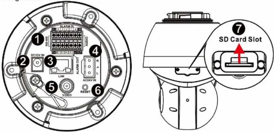
| No. | Connector | Definition |
| 1 | Audio/Alarm I/O & RS-485 Connector * | Audio/Alarm I/O & RS-485 connection |
| 2 | Power Connector (DC 12V) | DC 12V power connection |
| 3 | RJ-45 Port ** | IEEE 802.3at (PoE+) 4-Pair 60W only |
| 4 | Power Connector (AC 24V) | AC 24V power connection |
| 5 | BNC | For analog video output |
| 6 | Reset Button | Press the button with a proper tool for at least 20 seconds to restore the system. |
| 7 | SD Card Slot | Insert the SD card into the card slot to store videos and snapshots. Do not remove the SD card when the camera is powered on. |
*Do NOT connect external power supply to the alarm I/O connector of the camera.
**Please contact the manufacturer for compatible PoE injector.

NOTE: DV 12V power jack and AC 24V power connector cannot be used at the same time in case of unexpected damage.

NOTE: It is not recommended to record with the SD card for 24/7 continuously, as it may not be able to support long term continuous data read/write. Please contact the manufacturer of the SD card for information regarding the reliability and the life expectancy.
2. CAMERA CABLING
The outdoor models are being IP66-rated to prevent water from entering the camera. However, water might still enter the camera if it is being improperly installed. Please make sure the warnings below are strictly followed when installing the camera.
- Place all cables and the adaptor in dry and well-waterproofed environments, e.g. waterproof boxes. The purpose is to prevent moisture accumulation inside the camera and moisture penetration into cables.
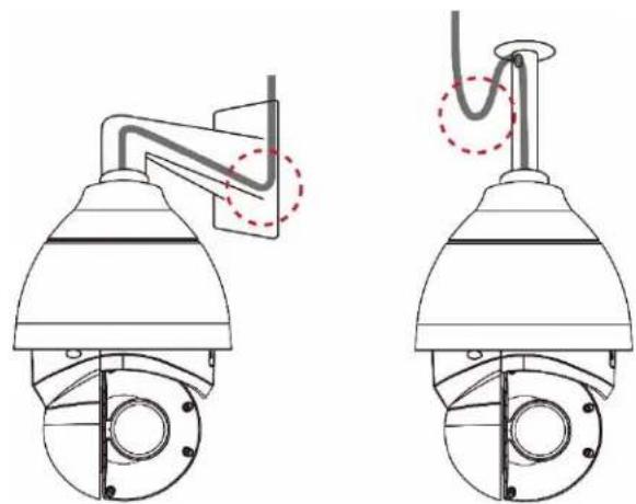
- While running cables, slightly bend the cables to a U-shaped curve to make a low point (as demonstrated in the figures below). The purpose is to prevent water from entering the camera along the cables from above.
natural_image
Technical line drawing of two security camera modules with no visible text or symbols- The cable entry hole of the outdoor mounting kit (indicated in the figure below) needs to be sealed with thread seal tape to avoid water from entering the camera.

natural_image
Technical line drawing of a mechanical assembly with a central component and red dashed ring (no text or symbols)2.1 POWER CONNECTION
To power up the camera, connect the DC 12V / AC 24V power adaptor to the power connector of the camera and the power outlet. Refer to the diagram and pin definition table below for AC 24V power connection.

Alternatively, users can use an Ethernet cable and connect it to the RJ-45 port of the camera and an IEEE 802.3at (PoE+) 4-Pair 60W switch.
Zero Downtime Power Switching (ZDT)
When users connect DC12V power jack and the RJ-45 port at the same time, the power input comes from the DC 12V connector. If the DC 12V power source fails, the camera will switch power input seemly to the RJ-45 port until the DC 12V power source is restored.
2.2 ETHERNET CABLE CONNECTION
To connect one end of the Ethernet cable to the RJ-45 connector of the camera, and plug the other end of the cable to the network switch or PC.

NOTE: In some cases, Ethernet crossover cable might be needed when connecting the camera directly to the PC.

NOTE: Check the status of the link indicator and activity indicator LEDs. If the LEDs are unlit, please check the LAN connection.
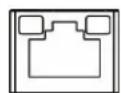
Green Link Light indicates good network connection.
Orange Activity Light flashes for network activity indication.
2.3 AUDIO/AIARM I/O & RS-485 CONNECTION
Please refer to the diagram and pin definition tables below for audio/alarm I/O & RS-485 connection.

| Pin | Definition | Pin | Definition | Pin | Definition | Pin | Definition |
| 1 | Audio In | 5 | Alarm In 1 | 9 | Alarm In 3 | 13 | RS-485 D- |
| 2 | Audio Out | 6 | Alarm Out A1 | 10 | Alarm Out B1 | 14 | RS-485 D+ |
| 3 | GND (Alarm I/O& RS-485) | 7 | Alarm In 2 | 11 | Alarm In 4 | ||
| 4 | GND (Audio I/O) | 8 | Alarm Out A2 | 12 | Alarm Out B2 |
3. SYSTEM REQUIREMENTS
To perform the camera via web browser, please ensure the PC is in good network connection, and meet the system requirement as described below.
| Items | System Requirement |
| Personal Computer | Minimum:1. Intel® CoreTMi5-2430M @ 2.4 GHz2. 2 GB RAM or more |
| Recommended:3. Intel® CoreTMi7-870 @ 2.93 GHz4. 8 GB RAM | |
| Operating System | Windows VISTA / Windows XP / Windows 7 |
| Web Browser | Microsoft Internet Explorer 10.0 or later (recommended)Firefox (32-bit)Safari |
| Network Card | 10Base-T (10 Mbps) or 100Base-TX (100 Mbps) or 1000Base-T operation |
| Viewer | ActiveX control plug-in for Microsoft IEApple QuickTime 7.7.7 or Before for Firefox |

NOTE: The ITE is to be connected only to PoE networks without routing to the outside plant or equivalent description.
4. ACCESS CAMERA
For initial access to the camera, users can search the camera through the installer program: DeviceSearch.exe, which can be found in "Device Search" folder in the supplied CD.
Accessing the Camera by Device Search Software
Step 1: Double click on the program Device Search.exe.
Step 2: After its window appears, click on the
Step 3: Find the camera in the list by its IP address and click on it. The default IP address of the camera is: 192.168.0.250.
Step 4: The default IP address of the camera may not be in the same LAN as the IP address of the PC. If so, the IP address of the camera needs to be changed. Right click on the camera and click
Step 5: The
Step 6: Click
Step 7: Click on the
Step 8: A prompt window requesting for default username and password will appear. Enter the default username and password shown below to login to the camera.
| Login ID | Password |
| Admin | 1234 |

NOTE: ID and password are case sensitive.

NOTE: It is strongly advised that administrator's password be altered for the security concerns. Refer to the Network IR PTZ Camera Menu Tree in the supplied CD for further details.
Installing DCViewer Software Online
For the initial access to the camera, a client program, DCViewer, will be automatically installed to the PC when connecting to the camera.
If the web browser doesn't allow Viewer installation, please check the Internet security settings or ActiveX controls and plug-ins settings (refer to section Setup Internet Security) to continue the process.
The Information Bar (just below the URL bar) may come out and ask for permission to install the ActiveX Control for displaying video in browser. Right click on the Information Bar and select
The download procedure of DCViewer software is specified as follows.
Step 1: In the DCViewer installation window, click on
Step 2: A status bar will be displayed to show the installation progress. After the installation is completed, click on
Step 3: Click on
Once the Viewer is successfully installed, the Home page of the camera will be shown as the figure below.

Zoom and Focus Adjustment
The live image will be displayed on the Home page when the camera is successfully accessed. If zoom or focus is not at the desired position, please use the function buttons on the Home page for adjustment. Refer to the Network IR PTZ Camera Menu Tree in the supplied CD for more details about the function buttons.
5. SETUP VIDEO RESOLUTION
Users can setup video resolution on Video Format page of the user-friendly browser-based configuration interface.
Video Format can be found under this path: Streaming> Video Format.

The default value of the video resolution is as below.
| 2M | Normal Mode | H.264- 1920 x 1080 (60/50 fps) + H.264- 720 x 480 (60 fps) / 720 x 576 (50 fps) |
| HDR Mode-2 Shutter | H.264- 1920 x 1080 (30/25 fps) + H.264- 720 x 480 (30 fps) / 720 x 576 (25 fps) | |
| HDR Mode-3 Shutter | H.264- 1920 x 1080 (30/25 fps) + H.264- 720 x 480 (30 fps) / 720 x 576 (25 fps) | |
| 3M | Normal Mode | H.264- 2048 x 1536 (60/50 fps) + H.264- 720 x 480 (60 fps) / 720 x 576 (50 fps) |
| HDR Mode-2 Shutter | H.264- 2048 x 1536 (30/25 fps) + H.264- 720 x 480 (30 fps) / 720 x 576 (25 fps) | |
| HDR Mode-3 Shutter | H.264- 2048 x 1536 (15/13 fps) + H.264- 720 x 480 (15 fps) / 720 x 576 (13 fps) | |
| 4M | Normal Mode | H.264- 2688 x 1512 (30/25 fps) + H.264- 720 x 480 (30 fps) / 720 x 576 (25 fps) |
| HDR Mode-2 Shutter | H.264- 2560 x 1440 (30/25 fps) + H.264- 720 x 480 (30 fps) / 720 x 576 (25 fps) | |
| HDR Mode-3 Shutter | H.264- 2560 x 1440 (15/13 fps) + H.264- 720 x 480 (15 fps) / 720 x 576 (13 fps) |
For more details about the combinations of video resolution, please refer to the Network IR PTZ Camera Menu Tree in the supplied CD.
6. CONFIGURATION FILES EXPORT / IMPORT
To export / import configuration files, users can access the Maintenance page on the user-friendly browser-based configuration interface.
The Maintenance setting can be found under this path: System>Maintenance.
Users can export configuration files to a specified location and retrieve data by uploading an existing configuration file to the camera. It is especially convenient to make multiple cameras having the same configuration.
Export
Users can save the system settings by exporting the configuration file (.bin) to a specified location for future use. Click on the
Upload
To upload a configuration file to the camera, click on
7. TECH SUPPORT INFORMATION
This chapter will introduce how to delete previously-installed DCViewer in the PC and how to setup the Internet security.
7.1 DELETE THE EXISTING DCVIEWER
For users who have installed the DCViewer in the PC previously, please remove the existing DCViewer from the PC before accessing to the IP camera.
Deleting the DCViewer
In the Windows
Deleting Temporary Internet Files
To improve browser performance, it is suggested to clean up all the files in the
Step 1: In the web browser, clicks on the
Step 2: Click on the
Step 3: In the appeared window, tick the box beside the
7.2 SETUP INTERNET SECURITY
If ActiveX control installation is blocked, please either set Internet security level to default or change ActiveX controls and plug-ins settings.
Internet Security Level: Default
Step 1: Start the Internet Explorer (IE).
Step 2: Click on the
Step 3: Click on the
Step 4: Down the page, click on the
ActiveX Controls and Plug-ins Settings
Step 1: Repeat Step 1 to Step 3 of the previous section above.
Step 2: Down the page, click on the
Step 3: Under
ActiveX controls and plug-ins settings:
- Binary and script behaviors.
- Download signed ActiveX controls.
- Download unsigned ActiveX controls.
- Allow previously unused ActiveX controls to run without prompt.
- Allow Scriptlets.
- Automatic prompting for ActiveX controls.
- Initialize and script ActiveX controls not marked as safe for scripting.
- Run ActiveX controls and plug-ins.
- Only allow approved domains to use ActiveX without prompt.
-
Script ActiveX controls marked safe for scripting*
-
Display video and animation on a webpage that does not use external media player.
Step 4: Click on
Step 5: Click on
Step 6: Close the browser window, and restart a new one later to access the IP camera.
- Caution and Preventive Tips
- Important Information
- Copyright
- Regulation
- Table of Contents
- Overview 4
- Camera Cabling 8
- System Requirements....11
- Appendix: Technical Specifications
- OVERVIEW
- FEATURES
- PACKAGE CONTENTS
- DIMENSIONS
- CONNECTORS
- CAMERA CABLING
- POWER CONNECTION
- Zero Downtime Power Switching (ZDT)
- ETHERNET CABLE CONNECTION
- AUDIO/AIARM I/O & RS-485 CONNECTION
- SYSTEM REQUIREMENTS
- ACCESS CAMERA
- Accessing the Camera by Device Search Software
- Installing DCViewer Software Online
- Zoom and Focus Adjustment
- SETUP VIDEO RESOLUTION
- CONFIGURATION FILES EXPORT / IMPORT
- Export
- Upload
- TECH SUPPORT INFORMATION
- DELETE THE EXISTING DCVIEWER
- Deleting the DCViewer
- Deleting Temporary Internet Files
- SETUP INTERNET SECURITY
- Internet Security Level: Default
- ActiveX Controls and Plug-ins Settings
- ActiveX controls and plug-ins settings:
Brand : Ernitec
Model : ORION DX 822IR
Category : Security Camera