IB IL 24 PWR IN/F-D-PAC - Uncategorized Phoenix - Free user manual and instructions
Find the device manual for free IB IL 24 PWR IN/F-D-PAC Phoenix in PDF.

| Product Type | Power Supply Module |
| Brand | Phoenix Contact |
| Model | IB IL 24 PWR IN/F-D-PAC |
| Input Voltage | 24 V DC (nominal) |
| Output Voltage | 24 V DC |
| Output Current | 2 A (typical) |
| Mounting Type | DIN Rail (35 mm) |
| Dimensions (W x H x D) | Approx. 48 x 100 x 80 mm |
| Weight | Approx. 150 g |
| Operating Temperature | -25°C to +60°C |
| Protection Features | Reverse polarity protection, overload protection |
| Connection Type | Spring-cage terminals |
| Diagnostics | LED status indication for input and output |
| Functions | Power supply for Inline stations, with diagnostics |
| Certifications | CE, UL, cUL (typical) |
| Maintenance | No regular maintenance required; clean with dry cloth |
| Spare Parts | Contact manufacturer for spare parts |
| Repairability | Not user-repairable; return to manufacturer |
| Safety Precautions | Disconnect power before installation |
| Warranty | Standard 2 years |
Frequently Asked Questions - IB IL 24 PWR IN/F-D-PAC Phoenix
User questions about IB IL 24 PWR IN/F-D-PAC Phoenix
0 question about this device. Answer the ones you know or ask your own.
Ask a new question about this device
Download the instructions for your Uncategorized in PDF format for free! Find your manual IB IL 24 PWR IN/F-D-PAC - Phoenix and take your electronic device back in hand. On this page are published all the documents necessary for the use of your device. IB IL 24 PWR IN/F-D-PAC by Phoenix.
USER MANUAL IB IL 24 PWR IN/F-D-PAC Phoenix
natural_image
Collection of green industrial electrical connectors and modules on a blue gradient background (no text or symbols visible)Automation terminals of the Inline product range
User manual
User manual
Automation terminals of the Inline product range
2017-04-25
Designation: IL SYS INST UM E
Revision: 08
This user manual is valid for:
All automation terminals in the Inline product range without bus couplers and bus-specific special features
Please observe the following notes
User group of this manual
The use of products described in this manual is oriented exclusively to qualified electricians or persons instructed by them, who are familiar with applicable standards and other regulations regarding electrical engineering and, in particular, the relevant safety concepts.
Explanation of symbols used and signal words

This is the safety alert symbol. It is used to alert you to potential personal injury hazards. Obey all safety measures that follow this symbol to avoid possible injury or death.
There are three different categories of personal injury that are indicated with a signal word.
DANGER This indicates a hazardous situation which, if not avoided, will result in death or serious injury.
WARNING This indicates a hazardous situation which, if not avoided, could result in death or serious injury.
CAUTION This indicates a hazardous situation which, if not avoided, could result in minor or moderate injury.

This symbol together with the signal word NOTE and the accompanying text alert the reader to a situation which may cause damage or malfunction to the device, hardware/software, or surrounding property.

This symbol and the accompanying text provide the reader with additional information or refer to detailed sources of information.
How to contact us
Internet Up-to-date information on Phoenix Contact products and our Terms and Conditions can be found on the Internet at: phoenixcontact.com
Make sure you always use the latest documentation. It can be downloaded at: phoenixcontact.net/products
Subsidiaries If there are any problems that cannot be solved using the documentation, please contact your Phoenix Contact subsidiary. Subsidiary contact information is available at phoenixcontact.com.
Published by PHOENIX CONTACT GmbH & Co. KG
Should you have any suggestions or recommendations for improvement of the contents and layout of our manuals, please send your comments to: tecdoc@phoenixcontact.com
General terms and conditions of use for technical documentation
Phoenix Contact reserves the right to alter, correct, and/or improve the technical documentation and the products described in the technical documentation at its own discretion and without giving prior notice, insofar as this is reasonable for the user. The same applies to any technical changes that serve the purpose of technical progress.
The receipt of technical documentation (in particular user documentation) does not constitute any further duty on the part of Phoenix Contact to furnish information on modifications to products and/or technical documentation. You are responsible to verify the suitability and intended use of the products in your specific application, in particular with regard to observing the applicable standards and regulations. All information made available in the technical data is supplied without any accompanying guarantee, whether expressly mentioned, implied or tacitly assumed.
In general, the provisions of the current standard Terms and Conditions of Phoenix Contact apply exclusively, in particular as concerns any warranty liability.
This manual, including all illustrations contained herein, is copyright protected. Any changes to the contents or the publication of extracts of this document is prohibited.
Phoenix Contact reserves the right to register its own intellectual property rights for the product identifications of Phoenix Contact products that are used here. Registration of such intellectual property rights by third parties is prohibited.
Other product identifications may be afforded legal protection, even where they may not be indicated as such.
Table of Contents
1 Documentation landscape of Inline 9
2 The Inline product range ....11
2.1 Features 11
2.2 Product description.... 12
3 Important information about voltage areas 15
3.1 Voltage areas for Inline Modular IO and Inline Block IO.... 15
3.2 Correct usage....16
3.3 Notes for Inline Modular IO....16
3.3.1 Safety notes for use in the low voltage area 16
3.3.2 Safety notes for electrical equipment used in industrial plants with a 400 V AC voltage ....17
3.3.3 Installation instructions and notes for low voltage terminals 17
3.3.4 Electronics base and connectors for the different voltage areas ..... 19
3.3.5 Safety mechanisms to prevent incorrect connection of terminals for different voltage areas ....20
3.3.6 Response to the connection of a 120 V AC or 230 V AC terminal in the 24 V DC area ....21
4 Inline product groups 23
4.1 Supported bus systems....23
4.2 Inline Modular IO terminals....24
4.2.1 Versions 24
4.2.2 Scope of supply 25
4.2.3 Transmission speed in the local bus 26
4.2.4 Example of an Inline station 27
4.2.5 Bus couplers and terminals with remote bus branch .....28
4.2.6 Power, segment, and accessory terminals 29
4.2.7 I/O terminals 36
4.2.8 Power-level terminals 38
4.2.9 Safety modules ....39
4.2.10 Programmable logic controllers (PLC) 42
4.2.11 Branch terminals ....43
4.2.12 Typical structure of an Inline Modular IO station 45
4.3 Inline Block IO modules....46
5 Structure and dimensions ....49
5.1 Structure and dimensions of Inline Modular IO terminals....49
5.1.1 Basic structure of terminals in the 24 V DC and 120 V AC/230 V AC areas 49
5.1.2 Electronics base 50
5.1.3 Connectors for terminals in the 24 V DC and 120 V AC/230 V AC areas 50
5.1.4 Basic structure of power-level terminals 51
5.1.5 Connectors for power-level terminals .....52
5.1.6 Function identification and labeling 53
5.1.7 Housing dimensions of terminals in the 24 V DC and 120 V AC/230 V AC areas ....54
5.1.8 Dimensions of power-level terminals 59
5.2 Structure and dimensions of Inline Block IO modules....60
5.2.1 Basic structure of modules 60
5.2.2 Function identification and labeling 61
5.2.3 Housing dimensions 62
6 Inline connectors 63
6.1 Basic structure and dimensions of Inline connectors.... 63
6.2 Connectors for the 24 V DC area....65
6.3 Connectors for the 120 V AC/230 V AC area (Inline Modular IO)....67
6.4 Numbering and labeling of terminal points.... 69
6.5 Terminal point keying 71
7 Electrical potential and data routing (Inline Modular IO) 73
7.1 Circuits and provision of supply voltages.... 73
7.1.1 Bus coupler supply ....73
7.1.2 Logic circuit ....74
7.1.3 Analog circuit 74
7.1.4 Main circuit 75
7.1.5 Segment circuit 76
7.1.6 Mains voltage for power-level terminals .....77
7.1.7 Example of a circuit diagram 78
7.2 Electrical potential and data routing....80
7.2.1 Arrangement of potential and data jumpers 80
7.2.2 Current and voltage distribution 84
8 Diagnostic and status indicators 87
8.1 Indicators on Inline Modular IO terminals....87
8.1.1 Indicators on bus couplers and terminals with remote bus branch ..... 87
8.1.2 Indicators available on different terminals in the Inline system 88
8.1.3 Indicators on power and segment terminals ....89
8.1.4 Indicators on I/O terminals 90
8.1.5 Indicators on power-level terminals 93
8.2 Indicators on Inline Block IO modules....94
8.2.1 Indicators in the bus system function area (BUS) 94
8.2.2 Indicators in the supply function area (PWR) 95
8.2.3 Indicators in the I/O function area (IN, OUT, IN/OUT) 96
9 Mounting/removing devices 99
9.1 Installation instructions ..... 99
9.1.1 Unpacking 99
9.1.2 Replacing a device 99
9.2 Basic information about mounting 100
9.3 Mounting distances 101
9.3.1 Mounting distances for Inline Modular IO terminals 101
9.3.2 Mounting distances for Inline Block IO modules 105
9.4 Grounding concept ......106
9.4.1 Functional earth ground (FE) 106
9.4.2 Protective earth ground (PE) (Inline Modular IO) 108
9.5 Shielding concept.... 109
9.5.1 Inline shielding concept 109
9.5.2 Shielding when connecting analog sensors and actuators ..... 109
9.6 Mounting/removal.... 111
9.6.1 Inline Modular IO: Mounting/removal 111
9.6.2 Inline Block IO: Mounting/removal 119
9.6.3 Order of the Inline Modular IO terminals 120
10 Connecting cables 123
10.1 Connecting cables using Inline connectors 123
10.1.1 Connecting unshielded cables 123
10.1.2 Connecting shielded cables using an Inline shield connector ..... 124
10.1.3 Connecting shielded cables using an Inline connector 127
10.2 Connecting the power supplies 128
10.2.1 Inline Modular IO: Supply options 128
10.2.2 Power supply requirements 129
10.3 Recommendation for supplying the supply voltage and resetting the voltage with regard to Inline Modular....130
10.3.1 Supply at the bus head 130
10.3.2 Supply at power terminals and boost terminals 131
10.3.3 Supply when connecting sensors and actuators in 1-wire technology 131
10.3.4 Testing the supply during startup 132
10.3.5 Behavior during reset at the bus coupler, Inline controller or field multiplexer 132
10.4 Connecting the bus.... 133
10.5 Connecting sensors and actuators 134
10.5.1 Connection methods for sensors and actuators 134
10.5.2 Connections used for digital input and output terminals .....135
10.5.3 The various connection methods for sensors and actuators ..... 136
10.6 Connections on a power-level terminal (Inline Modular IO) 139
10.6.1 Connecting or forwarding the incoming mains 140
10.6.2 Connecting the motor circuit connector 142
10.6.3 Connecting the brake module and brake (optional) .....144
10.6.4 Connecting the hand-held operator panel 145
10.6.5 Enabling the power level/24 V isolation ....146
11 Inline Modular IO: Technical data and ordering data 147
11.1 Technical data for Inline Modular IO....147
11.2 Ordering data 153
A Appendix: Inline Modular IO: Additional information 155
A 1 Use of Inline terminals at an elevation of more than 3000 meters....155
A 2 Tips for working with Inline.... 156
A 3 Configuration help for selecting the optimum analog input device for temperature recording .... 157
A 3.1 Inline Modular IO .... 157
A 3.2 Inline Block IO 159
A 4 Maximum cable lengths for analog devices.... 160
A 4.1 Inline standard .....160
A 4.2 Analog output ...... 161
A 4.3 Analog I/O 161
A 4.4 Inline ECO terminals .... 162
A 5 Temperature response of the terminals ....163
A 6 Calculation examples for power dissipation and working points .... 164
A 6.1 Constant power dissipation of the housing over the operating temperature range .... 164
A 6.2 Power dissipation of the housing within the operating temperature range depending on the ambient temperature .... 166
B Appendix: Software support....169
B 1 Overview of the software .... 169
B 2 Project+....170
B 3 CLIP PROJECT....171
B 4 Other software....171
C Appendix: Explanation of abbreviations and symbols....173
C 1 Explanation of abbreviations .... 173
C 2 Representations used in basic circuit diagrams....174
C 3 Frequently used symbols.... 175
D Appendix: Index....177
E Appendix: Revision history 181
1 Documentation landscape of Inline
The documentation for the Inline product range is modular, providing you with the optimum information for your specific bus system, Inline Modular IO terminal or Inline Block IO module.

The documentation can be downloaded at phoenixcontact.net/products.
For a comprehensive list of the documentation, please refer to the ordering data (see Section "Ordering data" on page 153).
Terminal-specific documentation can be found in the download area for the corresponding device.
Make sure you always use the latest documentation.

"Automation terminals of the Inline product range" user manual, IL SYS INST UM E (this manual)
For Inline Modular IO and Inline Block IO.
This manual is the higher-level system manual for Inline and describes the use of terminals/modules for all bus systems.

User manuals (system, bus coupler or special terminal)
For Inline Modular IO.
The additional user manuals either describe:
– A bus system (e.g., INTERBUS)
- A bus coupler in association with a bus system (e.g., PROFIBUS DP) or
- A special Inline terminal (e.g., counter terminal, positioning terminal)
Each manual only describes the relevant terminal and/or bus-specific special features. As the higher-level manual, the "IL SYS INST UM E" user manual also applies.

"INTERBUS & AUTOMATION - Terms and definitions" reference manual, IBSTERM RGUME
This manual provides an overview of technical terms and definitions in the field of INTERBUS & AUTOMATION.

Quick Start Guides
For Inline Modular IO.
A Quick Start Guide is available for various topics. A Quick Start Guide describes the startup of a system or a terminal step-by-step using an example.

Terminal/module-specific data sheets
For Inline Modular IO and Inline Block IO.
The data sheet describes the specific properties of each device.
This includes at the very least:
- Function description
– Local diagnostic and status indicators
- Pin assignment/terminal point assignment and connection example
- Programming data/configuration data
- Technical data
Application notes
For Inline Modular IO and Inline Block IO.
Application notes provide additional information about special topics, such as:

- Overview of Inline terminals that can be used at various bus couplers
AH IL BK IO LIST
The document will be replaced by the Project+ configuration software.
– Information about addressing 16-channel Inline Block IO modules
AH ILB 24 DI/DO 16 ADDRESS
– Information about addressing 32-channel Inline Block IO modules
AH ILB 24 DI/DO 32 ADDRESS
– General information about the safety-related segment circuit
AH EN IL SAFE
– General information about use in zone 2 potentially explosive areas
AH EN IL EX ZONE 2
– Example for the use of a terminal with a specific software tool
– Example for the communication of a terminal with a specific control system
– Information about firmware versions of specific terminals
– Information about firmware updates

Package slips
For Inline Modular IO and Inline Block IO.
A package slip contains key information for the electrical installation of a device or group of devices. This includes, for example:
- Short description
- S a f e t y n o t e s
- Mounting/removal
– Terminal point assignment
2 The Inline product range
The Inline product range consists of:
- Inline Modular IOs: Modular terminals
- In line Block OS : Comp a c remote

This manual mainly describes the Inline Modular IOs, which are referred to as Inline terminals. For information about the Inline Block IOs, please refer to the module-specific data sheets.
2.1 Features
Inline Modular IO
- Can be easily installed side by side without tools
- Open, flexible, and modular structure
- Terminals of varying widths can be combined to create a time-saving, compact, and cost-effective station structure
- 2-slot terminals:
These terminals enable optimum adaptation to the desired configuration. They enable a flexible and compact station structure without unnecessary reserve installation space. - 8-slot terminals:
These terminals provide a fast and effective station structure for larger stations. - Functional orientation of the control box or control cabinet
The modular structure makes it possible to assemble standard function blocks in advance. Parts of the system can be started up independently of one another. This means that pretests can be carried out when the system is set up and the whole system can be adapted and extended.
– Automatic creation of isolated groups, potential circuits, and data circuits - The amount of costly parallel wiring is reduced
Within a station, potential and data routing can be carried out without additional wiring.
– Supports all popular bus systems
Inline Block IO
- Integrated bus interface for all popular bus systems
– High channel density - C o m p a c t 5 5 m m f l a t d e s i g n
- Can be easily installed without tools
- Same look and feel as Inline Modular IO
2.2 Product description
| Automation terminals with various functions are available within the Inline product range.With just a few exceptions, the automation terminals consist of an electronics base (Inline Modular IO) or an electronic module (Inline Block IO) and one or more connectors for connecting the I/O or power supply. The electronics can be replaced without removing a single wire from the connector. | |
| Inline Modular IO versions | The Inline product range offers terminals for all automation tasks:- Bus couplers to integrate the Inline station into various bus systems, some with input and output function for digital signalsThe bus can be connected using copper or fiber optic technology.- Terminals with remote bus branch for opening an INTERBUS remote bus branchThe remote bus branch can be connected using copper or fiber optic technology.- Terminals for supplying the supply voltages and segmenting the station (with and without fuse)- Accessory terminals (potential distributor terminals, distance terminals)- Input and output terminals for digital and analog signals- Power-level terminals for switching, protecting, and monitoring three-phase standard motors- Branch terminals for integrating further product ranges (e.g., integration of a Fieldline Modular local bus in the Inline station) or to extend the local bus by several rows- Terminals for open and closed-loop control, communication, and position detection- Safety modules- Programmable terminals (CPU and Inline Controller) |
| Inline Block IO versions | - Input modules, output modules, and I/O modules for digital and analog signals- Bus interface is integrated in the module |
| Mounting location | Inline Modular IO terminals and Block IO modules meet IP20 protection. They can be used in closed control cabinets or in control boxes (terminal boxes) with IP54 protection or higher according to EN 60529. The compact design means that most Inline Modular IO terminals and all Block IO modules can be installed in standard terminal boxes.Please observe the mounting distances when selecting the housing (see Section “Mounting distances” on page 101). |
| Mounting | Inline Modular IO terminals and Block IO modules can be snapped onto DIN rails without tools. Potential and data jumpers are automatically created when the Inline Modular IO terminals are properly installed.See Section “Mounting/removing devices” on page 99. |
| Bus connection (network) | Inline Modular IO: The Inline station is integrated in the bus system via a bus coupler or controller. The bus is controlled by the Inline station through data routing. |
| Inline Block IO: The bus interface is integrated in the module. The bus is connected directly to the I/O module. | |
| I/O connection | The Inline terminals and Block IO modules have connectors for 1, 2, 3, and 4-wire sensors or actuators. The wires are connected using spring-cage technology. For more detailed information, please refer to the individual sections. |
3 Important information about voltage areas
3.1 Voltage areas for Inline Modular IO and Inline Block IO
Inline Block IO modules are available for the SELV area
Inline Modular IO terminals are available for the SELV and low voltage areas. The terminals are divided into three product groups according to their use in a specific voltage area and their function.
Table 3-1 Voltage areas and corresponding terminal designations for Inline
| Voltage area Voltage used for Inline Product group | ||
| SELV 24 V DC Low-level signal terminals; | Inline Block IO modules | |
| Low voltage 120 V AC Low voltage terminals; AC | terminals | |

Observe the safety notes in the following sections when working outside the SELV area.
3.2 Correct usage
Inline Block IO modules and Inline Modular IO terminals should only be used according to the instructions in the terminal-specific data sheets and this user manual. Phoenix Contact accepts no liability if the device is used for anything other than its designated use.
When used in the SELV area:

NOTE: Disregarding this warning may result in malfunction
Do not replace terminals while the power is connected.
Before removing or mounting a terminal, disconnect power to the entire station.
Make sure the entire station is reassembled before switching the power back on.
When used in the low voltage area:

WARNING: Dangerous contact voltage
Do not replace terminals while the power is connected.
Before removing or mounting a terminal, disconnect power to the entire station.
Make sure the entire station is reassembled before switching the power back on.

WARNING: Dangerous contact voltage
Please note that there are dangerous contact voltages when switching circuits that do meet SELV requirements.
When working on the terminals and wiring, always switch off the supply voltage and ensure it cannot be switched on again.
3.3 Notes for Inline Modular IO
3.3.1 Safety notes for use in the low voltage area
Only qualified personnel (qualified electricians or persons instructed in electrical engineering) may work on Inline terminals outside the SELV area.

The instructions given in the terminal-specific data sheets must be followed during installation and startup.
An electrician is a person who, because of their education, experience, and instruction, and their knowledge of relevant standards, can assess any required operations and recognize any possible dangers. (Definitions according to DIN VDE 1000-10:1995).
A person instructed in electrical engineering is someone who has been instructed by an electrician in their required tasks and the possible dangers caused by incorrect handling and, if necessary, has also been informed of the necessary safety equipment and safety measures. (Definitions according to DIN VDE 1000-10:1995).
3.3.2 Safety notes for electrical equipment used in industrial plants with a 400 V AC voltage

WARNING: Dangerous contact voltage
The electrical power-level terminals for the 400 V AC area and connected machines refer to equipment used in industrial plants. During operation, this equipment has dangerous, live, moving or rotating parts. These can therefore cause considerable damage to health or equipment, e.g., due to the unauthorized removal of protective covers or inadequate maintenance.
- Only qualified personnel may work on the power-level terminals or system (for the definition, see Section 3.3.1 on page 16).
- When working on the power-level terminals and the system, you must always keep the operating instructions and other items of product documentation to hand and observe the information therein.
- It is prohibited for unqualified personnel to work on the power-level terminals, on the machine or in their vicinity.
The instructions given in the terminal-specific data sheets must be followed during installation and startup.
The notes on the procedures and the circuit details presented in the terminal-specific data sheets should be understood in a general sense and the relevant application should be tested to see if they apply.
Phoenix Contact cannot guarantee the suitability of the procedures or the circuit suggestions described for the relevant application.
3.3.3 Installation instructions and notes for low voltage terminals

WARNING: Dangerous contact voltage
Please note that there are dangerous contact voltages when switching circuits that do meet SELV requirements.
Connecting and disconnecting the terminals for the 120 V AC and 230 V AC voltage areas is only permitted if the power supply is disconnected.
When working on the terminals and wiring, always switch off the supply voltage and ensure it cannot be switched on again.

WARNING: Dangerous contact voltage in the event of ground faults
(e.g., because the FI circuit breaker has not tripped or the star point connection is "free") Inline terminals for the 120 V AC and 230 V AC voltage areas should only be operated in grounded AC voltage networks (AC networks).
3.3.3.1 Structure of a 120 V AC/230 V AC area
A 120 V AC/230 V AC area must have a power terminal at one end and an end terminal at the other.
I/O terminals for these voltage areas can be used between these terminals. The number of terminals is limited by the system limits of the bus system and the Inline system (see Section 11, "Inline Modular IO: Technical data and ordering data").
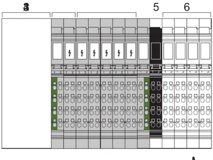
Figure 3-1 Typical structure of an Inline station with different voltage areas
1 Bus coupler
2 Power terminal for the 120 V AC or 230 V AC area
3 Various I/O terminals for the 120 V AC or 230 V AC area
4 End terminal for the 120 V AC or 230 V AC area
5 Power terminal for the 24 V DC area
6 Various I/O terminals for the 24 V DC area
3.3.3.2 Fuse protection for a 120 V AC/230 V AC area
Each 120 V AC/230 V AC area must be protected by its own external fuse. Select the rating of the fuse according to the strength of the cable. The maximum fuse value is 8 A. For additional restrictions, please refer to the data sheets for the power terminals.
3.3.3.3 Connecting the power supply and I/O in the 120 V AC/230 V AC area

WARNING: Dangerous contact voltage
The supply voltage must only be provided at the appropriate power terminal.
If you provided voltage to several places in an incomplete Inline station, there would be a danger of touching live parts.
The connecting cables of all actuators and sensors must only be connected to the Inline terminals for the relevant voltage area. The use of external bus bars for group potentials is not permitted.
3.3.3.4 Interrupting PE jumpering in the 120 V AC/230 V AC area
The PE jumper begins at the power terminal of the 120 V AC/230 V AC area and, in a complete AC voltage area, ends at the end terminal.
If a terminal is removed from this area, the PE jumper is interrupted.
If the installation instructions have been followed, all subsequent terminals will be disconnected.
3.3.4 Electronics base and connectors for the different voltage areas
Power-level terminals are located in a power housing.
Low-level signal terminals and low voltage terminals are located in the same type of housing, which is referred to as low-level signal housing. An external feature that distinguishes the base and the corresponding connectors of low voltage terminals from the base and connectors of low-level signal terminals is their color:
Table 3-2 Base and connector colors for the different voltage areas
| Area | Terminal | Connector | Other differences |
| Low-level signal (24 V DC) | Green Green or black | Light color for function identification (e.g., light blue) | |
| Low voltage (120 V AC/ 230 V AC) | Gray Gray Dark color for function identification (e.g., dark blue) with white lightning bolt | ||
3.3.5 Safety mechanisms to prevent incorrect connection of terminals for different voltage areas
3.3.5.1 Protection against the insertion of 24 V DC terminals and power-level terminals in the 120 V AC/230 V AC area
Low-level signal terminals and power-level terminals cannot be snapped-on within a low voltage area because there is no keyway on the right-hand side of the low voltage terminals (120 V AC/230 V AC).

WARNING: Dangerous contact voltage
The power terminals for the 24 V DC area can be inserted in a 120 V AC/230 V AC area. The minimum isolating distance in this case is the distance between two adjacent connectors. This isolating distance is not permitted. Therefore, only use end terminals that are designed for terminating the 120 V AC/230 V AC area.
3.3.5.2 Protection against the connection of 24 V connectors to 120 V AC/230 V AC terminals
The two terminal points for the low voltage I/O terminals are closed using filler plugs. The connectors for low-level signal terminals therefore do not fit on the low voltage terminals.
Exception 1: The low-level signal connectors can be plugged into 120 V AC/230 V AC power terminals.
This connection error has no hazardous effect on the electrical components, but it can lead to system malfunctions.
Only the appropriate connectors should therefore be plugged into the low voltage power terminals.
Exception 2: The low-level signal connectors can be plugged into relay terminals. Because the relay outputs are floating, this connection error has no adverse effects.
3.3.5.3 Protection against the connection of live 120 V AC/230 V AC connectors in the 24 V DC area
If the connectors for the I/O terminals are wired according to the installation instructions, they are disconnected from the power supply when removed.
The following connectors may be live in the low voltage area:
1 Connectors of the power terminals for the 120 V AC and 230 V AC areas
2 Connectors for relay terminals
These connectors are closed using filler plugs in some places and therefore do not fit on the terminals of the 24 V area.
3.3.6 Response to the connection of a 120 V AC or 230 V AC terminal in the 24 V DC area
An AC terminal can be inserted in the 24 V DC area. The effects are described in Table 3-3.

A 24 V DC terminal cannot be inserted accidentally in an AC area as these terminals are not mechanically compatible.
Table 3-3 Response to the connection of an AC terminal in the 24 V DC area
| AC terminal in the 24 V DC area | Effect/description |
| AC power terminal in the 24 V DC area | Specified interface between a 24 V DC area and an AC area.The AC power terminal consists of two function parts:- The left-hand part interrupts the jumpering of U_S, U_M, GND , and FE- The connections for the power supply and the jumper contacts for L, N, and PE are on the right-hand part |
| Digital AC output terminal in the 24 V DC area | No direct danger to people.If the output is activated, the Triac output may be forced to trip and no longer switch off because the supply voltage does not pass through zero. NOTE: Possible malfunctionThis is likely to be caused by a malfunction of the actuator connected to the relevant output. NOTE: Possible malfunctionThis is likely to be caused by a malfunction of the actuator connected to the relevant output. |
| Digital AC input terminal in the 24 V DC area | No danger to people or machines.The input does not function due to missing ground. |
| Relay terminal in the 24 V DC area | No direct danger to people.The module has no diagonal routing, so there is no direct danger from the terminal, even with a 230 V connector. This means that the shortest isolating distance is the distance from one connector to the next. This isolating distance is not permitted. Therefore, insert a distance terminal (order designation IB IL DOR LV-SET) before and after the relay terminal. |
| AC end terminal in the 24 V DC area | No danger to people or machines.The terminal offers neither diagonal routing nor connector connection. |
4 Inline product groups
The following sections provide an overview of the Inline product groups. For specific information about the individual terminals/modules, please refer to the specific data sheets and the individual sections in this manual.

The product range is continuously growing. Additional information can be found in the latest catalog or on the Internet at phoenixcontact.net/products.
4.1 Supported bus systems
Inline devices are available for the following bus systems:
Table 4-1 Bus systems supported by Inline
| Bus system | Inline Modular IO | Inline Block IO |
| PROFINET IO Yes Yes | ||
| INTERBUS Yes Yes | ||
| PROFIBUS DP Yes Yes | ||
| Ethernet/IPTM Yes Not at present | ||
| Ethernet TCP/IP Yes Yes | ||
| Modbus/TCP Yes Yes | ||
| Modbus/RTU Yes Not at present | ||
| Sercos II | Yes Not at present | |
| Sercos III | Yes Yes | |
| DeviceNetTM | Yes Yes | |
| CANopen® | Yes Yes | |
| Mechatrolink | Yes Not at present | |
| Bluetooth | Not at present Yes |
4.2 Inline Modular IO terminals
4.2.1 Versions
4.2.1.1 Extreme conditions version (IB IL ... -XC-PAC)
Thanks to special engineering measures and tests as well as coated PCBs, the XC modules can be used under extreme ambient conditions.
For use in the extended temperature range from -40^ to +70^ , please observe Section "Tested successfully: use under extreme ambient conditions", and the notes in the terminal-specific data sheet.
The function of an XC version is the same as the function of the corresponding standard version.
Tested successfully: Use under extreme ambient conditions
XC terminals have been tested successfully over 250 temperature change cycles in accordance with IEC 61131-2 in the range from -40^ to +70^ .
The following conditions were observed:
- The Inline devices for all connecting cables were connected with a minimum conductor cross section of 0.5mm^2
- The Inline station was assembled on a wall-mounted horizontal DIN rail
– Fans were used to ensure continuous movement of air in the control cabinet - The Inline station was not exposed to vibration or shock
- The Inline station was operated with a maximum of 24.5 V (ensured by using regulated power supply units)
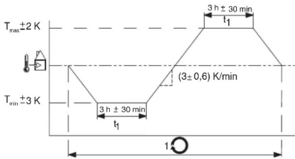
Figure 2 Temperature change cycle

Temperature in the control cabinet/ambient temperature

Cycle

WARNING:
The terminal is not approved for use in potentially explosive areas.
The terminal is not approved for use in safety technology.
4.2.1.3 ECO version (IB IL ...-ECO)
ECO version
Inline ECO terminals enhance the Inline portfolio by inexpensive and especially simple terminals providing basic functionality. You can recognize these terminals by the "ECO" specified in the order designation. You can install Inline ECO terminals in series behind Inline bus couplers or Inline controllers, and combine them with standard terminals. Please note that if an Inline ECO terminal is used, the permissible ambient temperature for the station is limited to 0 °C to 55 °C.
Features of Inline ECO terminals
- No parameterization required (for digital and analog input and output terminals)
- Limited temperature range for operation: 0 °C ... 55 °C
– Scope of supply: electronics base and required connectors
- Analog and function terminals come without shield plug. For notes on shielding, please refer to Section “Connecting cables using Inline connectors” on page 123.
- Labeling fields are not included. For ordering data for labeling fields, please refer to the Section "Ordering data for accessories" on page 153.
4.2.2 Scope of supply
Depending on the type, Inline terminals are available with varying accessories. Type “-PAC” and “-ME” Inline terminals come with:
- The electronics base,
– all required Inline connectors, and
– all required labeling fields.
Inline connectors are designed for connecting the cables. They are required for correct operation of the terminal.
Labeling fields are used for clear marking. They are optional accessories.
In the past, Inline terminals were available as stand-alone items without accessories. For a stand-alone item without accessories, the Inline connectors have to be ordered separately.
If your item comes without labeling field, you can separately order labeling fields as optional accessories.
Table 4-1 Scope of supply for Inline terminals, depending on the type
| Type (example) Connector Labeling field | |
| IB IL 24 DO 4-PAC included in scope of supply included in scope of supply | |
| IB IL 24 DO 4-ME included in scope of supply included in scope of supply | |
| IB IL 24 DO 4/EF-ECO included in scope of supply accessories (optional) | |
| IB IL 24 PWR IN accessories (required) accessories (optional) | |
4.2.3 Transmission speed in the local bus
It is possible to operate at a transmission speed of 500 kbps or 2 Mbps within an Inline station.
Items designed for 2 Mbps are indicated by the extension "-2MBD" in the order designation. The versions without this extension are designed for 500 kbps.

In the product range, terminals with 500 kbps are basic versions. Some (not all) of the terminals are also available as 2MBD versions. Additional information about the available terminals can be found in the latest catalog or on the Internet at phoenixcontact.net/products.

NOTE:
Use the same transmission speed throughout an Inline station. The station cannot operate otherwise. Make sure that your bus coupler supports this transmission speed in the local bus.
For INTERBUS, a separate bus coupler version is available for each transmission speed. Bus couplers for other bus systems may only support terminals with 500 kbps or even both transmission speeds in the local bus.

For details of which transmission speed your bus coupler can use within the local bus, please refer to the corresponding documentation.
Examples Examples of order designations:
IB IL 24 DO 4-PAC 500 kbps; complete with accessories (connector and labeling field)
IB IL 24 DO 4-2MBD-PAC 2 Mbps; complete with accessories (connector and labeling field)
Convention for this document
The PAC version for 500 kbps is used in the following examples. However, all information also applies for the versions for 2 Mbps and the versions without accessories.
4.2.4 Example of an Inline station
Figure 4-1 shows a typical Inline station. It contains just a few terminals from the extensive product range. The functions and special features of the individual product groups are described in the sections below.
In addition, Figure 4-1 also shows the structure of the main and segment circuits. This structure can be created using power and/or segment terminals (see Section "Power, segment, and accessory terminals" on page 29).
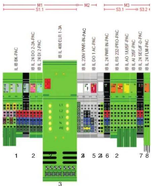
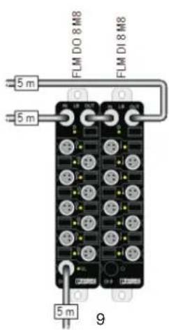
Figure 4-1 Typical Inline station
1 Bus coupler (here: with supply voltages supplied)
2 I/O terminals for 24 V area
3 Power-level terminal
4 Power and end terminal for a 230 V area
5 Output terminal for 230 V area
6 Power terminal for 24 V area
7 Segment terminal
8 Branch terminal (here: to connect Fieldline Modular M8 devices)
9 Fieldline Modular M8 devices
M1, M2, M3 Main circuit 1, 2, 3
S1.1 Segment circuit 1 in main circuit 1
S3.1, S3.2 Segment circuit 1 and 2 in main circuit 3
4.2.5 Bus couplers and terminals with remote bus branch

Bus coupler for Profinet: IL PN BK DI8 DO4 2TX-PAC
natural_image
Technical line drawing of an electrical component with no visible text or symbolsTerminal with remote bus branch: IBS IL 24 RB-T-PAC
Figure 4-2 Example: Bus coupler and terminal with remote bus branch
4.2.5.1 Bus coupler
A bus coupler is required to connect an Inline station to a bus. Bus couplers are available for various bus systems (see Table 4-1).

The bus couplers are described in detail in a separate document. Not all Inline terminals can be used with every bus coupler. For an overview of the compatibility between Inline terminals and bus couplers for various bus systems, please refer to "AH IL BK IO LIST".
4.2.5.2 Terminals with remote bus branch
A terminal with remote bus branch can only be used in an INTERBUS system.

For more detailed information about this, please refer to the IB IL SYS PRO UM E user manual or the data sheet for the terminal with remote bus branch.
4.2.6 Power, segment, and accessory terminals

For more detailed information about the voltages used within an Inline station, please refer to Section “Circuits and provision of supply voltages” on page 73.
4.2.6.1 Overview of power and segment terminals
Power terminals and segment terminals are available to supply the station with I/O voltage. The segment terminals extend the power terminals. The segment terminals make it possible to create different segments within a main circuit. Different types can be used to meet your requirements.
Table 4-2 Overview of power and segment terminals
| Designation TypeSupply/ | provision | Fuse Diagnostics | (bus device) | Fused area | |
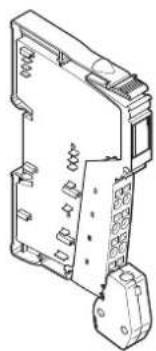
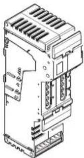
| IB IL 24 PWR INIB IL 24 PWR IN-PAC | Power terminal | U_M/U_S | No No None | ||
| IB IL 24 PWR IN/F-PAC Yes No Main | |||||
| IB IL 24 PWR IN/2-F-PAC | Yes No | Main circuit and segment circuit | |||
| IB IL 24 PWR IN/F-D-PAC | Yes Yes (500 kbps) | Main circuit | |||
| IB IL 24 PWR IN/2-F-D-PAC | Yes Yes (500 kbps) | Main circuit and segment circuit | |||
| IB IL 24 PWR IN/2-F-D-2MBD-PAC | Yes Yes (2 Mbps) | Main circuit and segment circuit | |||
| IB IL 24 PWR IN/2F-DF-PAC | Yes Yes (500 kbps) | Main circuit and segment circuit | |||
| IB IL 24 PWR IN/2F-DF-2MBD-PAC | Yes Yes (2 Mbps) | Main circuit and segment circuit | |||
| IB IL 24 PWR IN/R/L-0.8A-PAC | U_24V(U_L) | No | No | None | |
| IB IL 24 PWR IN/R-PAC | U_24V(U_L/U_ANA)/U_M/U_S | No No None | |||
| IB IL 24 PWR IN/PS-PAC | No No None | ||||
| IB IL 120 PWR IN-PAC | L | No No None | |||
| IB IL 230 PWR IN-PAC | No No None | ||||
| IB IL 230 PWR IN/F-D-PAC | Yes Yes (500 kbps) | Main circuit | |||
| IB IL 24 SEG-PAC | Segment terminal | U_S | No No None | ||
| IB IL 24 SEG/F-PAC | Yes No Segment circuit | ||||
| IB IL 24 SEG/F-D-PAC | Yes | Yes (500 kbps) | Segment circuit | ||
| IB IL 24 SEG-ELF-PAC | Yes (electronic) | Yes (500 kbps) | Segment circuit |
Table 4-2 Overview of power and segment terminals
| Designation TypeSupply/ | provision | Fuse Diagnostics | (bus device) | Fused area | |
| XC versions | |||||
| IB IL 24 PWR IN-XC-PAC | Power terminal | U_M/U_S | No No None | ||
| IB IL 24 PWR IN/2-F-XC-PAC Yes N | Main circuit and segment circuit | ||||
| IB IL 24 PWR IN/R-XC-PAC | U_24V(U_L/U_ANA)/ U_M/U_S | No No None | |||
| IB IL 24 SEG/F-XC-PAC | Segment terminal | U_S | Yes No Segment circuit | ||
U_M Main voltage
U_S Segment voltage
U_24V 24 V supply, generated from voltages U_L and U_ANA
U_L Communications power
U_ANA Analog voltage

NOTE: Consequential damage
Protect the power supply externally, regardless of the power and/or segment terminal used.

Terminals that are not bus devices can be used in a local bus with 500 kbps as well as a local bus with 2 Mbps.
4.2.6.2 Power terminals
A power terminal is used to supply the required voltages to the internal station potential jumpers. Several power terminals can be used in one station. This means that different circuits can be electrically isolated and areas with different voltages can be created within the station (e.g., 24 V DC and 230 V AC).
All power terminals are used to supply the main voltage and/or segment voltage.
A 24 V supply voltage is also supplied at the IB IL 24 PWR IN/R-PAC and IB IL 24 PWR IN/PS-PAC terminals, from which the communications power U_L and the analog voltage U_ANA are generated. These terminals are mainly designed to boost the communications power and analog voltage when the maximum current carrying capacity of the potential jumpers for U_L/U_ANA or the maximum current carrying capacity of the bus coupler for U_L/U_ANA is reached.
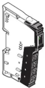
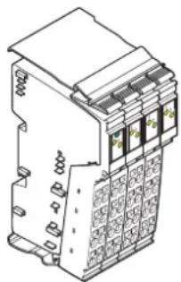
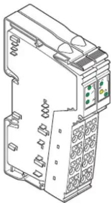
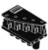
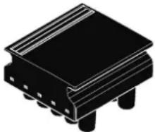
natural_image
Technical line drawing of a mechanical or electronic component with no visible text or symbolsFigure 4-3 Example of a power terminal: IB IL 24 PWR IN-PAC
Voltage areas
Depending on the power terminal, it is possible to work with 24 V DC, 120 V AC or 230 V AC within an Inline station.
To utilize different voltage areas within a station, a new power terminal must be used for each area.

WARNING: Dangerous contact voltage
When the power terminal is removed, the metal contacts are freely accessible. With 120 V AC or 230 V AC power terminals, it should be assumed that dangerous contact voltage is present. You must disconnect power to the station before removing a terminal.
If these instructions are not followed, there is a danger of damage to health or even of a life-threatening injury.

Observe safety notes
Observe the notes provided in Section “Important information about voltage areas” on page 15 when using voltages outside the SELV area.
IL SYS INST UM E
| Potential jumpers | The power terminal interrupts all potential jumpers for the voltages to be reinjected, and recreates all potential jumpers (see also Section “Electrical potential and data routing (Inline Modular IO)” on page 73). |
| Carrying capacity of the jumper contacts | The maximum current carrying capacity of the jumper contacts on the side is specified in Section “Current and voltage distribution” on page 84. |
| Electrical isolation | The power terminal is used to create electrically isolated I/O areas within a station. |
| Functional earth grounding (24 V DC) | 24 V power terminals are connected to functional earth ground when they are snapped onto the grounded DIN rail via the FE spring on the bottom of the terminal. This spring is connected to the FE potential jumper and to the terminal points for an FE connection.If the previous terminal is a 24 V terminal, the power terminal is connected to the FE potential jumper of the station when it is snapped onto this terminal. |
| Required additional functional earth grounding (24 V DC) | A 120 V AC and 230 V AC voltage level area interrupts the FE jumper, which is connected to FE via the additional functional earth grounding at the bus coupler. A 24 V DC power terminal that is at a different voltage area must therefore be reconnected to functional earth ground via the FE connection to ensure reliable functional earth grounding of the station even if the FE spring is dirty or damaged. Connect the terminal points for the FE connection to a grounded PE terminal (see Section “Grounding concept” on page 106). |
| Protective earth grounding(120 V AC/230 V AC) | The PE terminal point of the power connector connects the 120 V AC and 230 V AC power terminals to protective earth ground (PE). This terminal point is connected to the PE potential jumper, which is led through the entire 120 V AC or 230 V AC voltage area. |
| Additional documentation |

For more detailed information about the function, properties, and wiring of the individual terminals, please refer to the terminal-specific documentation.
4.2.6.3 Segment terminals
Segment terminals can only be used in the 24 V DC area. Segment terminals can be used to create partial circuits (segment circuits) within the main circuit.
On segment terminals without a fuse, the connection between the main circuit U_M and the segment circuit U_S must be established using a jumper or a switch. Segment terminals with a fuse establish this connection automatically.

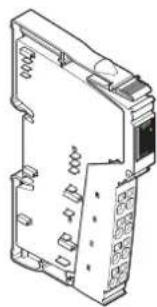
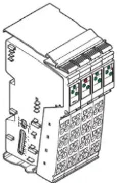
natural_image
Technical line drawing of an electrical enclosure or switchgear component (no text or symbols visible)Figure 4-4 Example of a segment terminal: IB IL 24 SEG-PAC
U_M The potential jumper for the main circuit U_M is not interrupted in the segment terminal. The potential for the segment circuit U_S is tapped from the potential jumper at the segment terminal.
U_S The segment terminal interrupts the segment circuit U_S in the potential jumper of the previous terminal.
For more detailed information about the supply voltages, please refer to Section "Circuits and provision of supply voltages" on page 73.
Carrying capacity of the jumper contacts The maximum current carrying capacity of the jumper contacts on the side is specified in Section "Current and voltage distribution" on page 84.
Functional earth grounding The terminal is connected to functional earth ground when it is snapped onto the grounded DIN rail via the FE spring on the bottom of the terminal. This spring is connected to the FE potential jumper and to the terminal points for an FE connection.
When snapped onto the previous terminal, the segment terminal is connected to the FE potential jumper of the station.
Additional documentation

For more detailed information about the function, properties, and wiring of the individual terminals, please refer to the terminal-specific documentation.
4.2.6.4 Accessory terminals
Potential distributor terminals and distance terminals are available as accessory terminals.
Potential distributor terminals (for GND and 24 V) are designed for the economical return wiring of sensor and actuator cables when using Inline terminals with 1-wire termination.
The distance terminal set creates the specified creepage distance when using AC terminals. Both distance terminals interrupt the potential jumpers for the main voltage, segment voltage, ground, and functional earth ground.
natural_image
Isometric line drawing of a mechanical or electrical component with no visible text, numbers, or symbols.Figure 4-5 Example of a potential distributor terminal: IB IL PD 24V-PAC
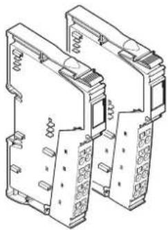
natural_image
Technical line drawing of two mechanical components with spring and housing (no text or symbols)Figure 4-6 Distance terminal set: IB IL DOR LV-SET-PAC
Additional documentation

For more detailed information about the function, properties, and wiring of the individual terminals, please refer to the terminal-specific documentation.
4.2.6.5 Supply and segmentation options
Figure 4-7 provides an overview of supply and segmentation. For more detailed information, please refer to Section "Electrical potential and data routing (Inline Modular IO)" on page 73.
Supply and segmentation Structure of an AC area
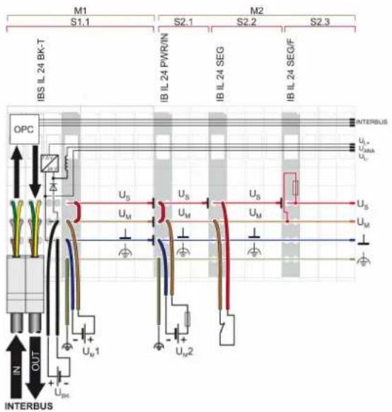
Segment terminals can be used to create different segment circuits within a 24 V area of an Inline station.
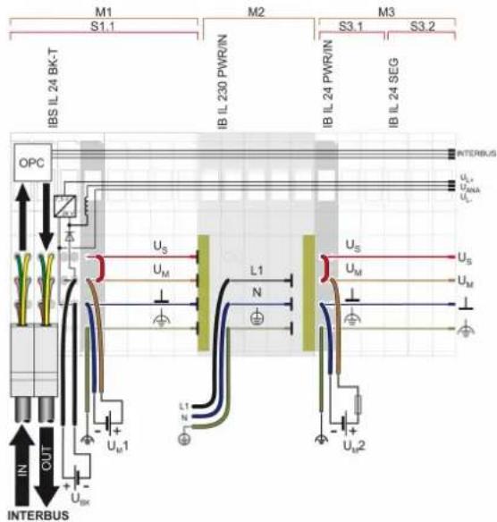
Special AC power and segment terminals can be used to create AC areas within an Inline station.
Integration of power-level terminals
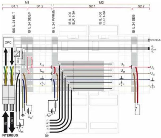
A 400 V power bus is supplied at the first power-level terminal and jumpered further.
Figure 4-7 Supply and segmentation options
4.2.7 I/O terminals
Functions
Terminals with different functions are available for low-level signals. These include the following terminals, for example: The text in brackets indicates the function according to the order designation.
– Digital input and output terminals (DI, DO)
– Analog input and output terminals (AI, AO)
- Relay terminals (DOR)
– Temperature measurement terminals (TEMP)
- Communication terminals
- Communication terminals with serial interface (RS232, RS485/422)
- Inline/AS-i master (ASI MA)
– DALI terminals (DALI)
– Position detection terminals (INC-IN, IMPULSE-IN, SSI-IN)
- Terminals for open and closed-loop control
– Function terminals (PWM, CNT)
- Positioning terminals (SSI, INC)
– Temperature controller terminals (TEMPCON)
Digital input and output terminals and relay terminals are available for the low voltage area.
These terminals are available in different sizes. This enables you to set up the station in a modular way so that it meets your application requirements.
natural_image
Isometric line drawing of a multi-pin electrical terminal block (no text or symbols)Figure 4-8 Example of a digital input terminal: IB IL 24 DI 8-PAC
Protection
Overload protection of the system is provided centrally by a fuse in the power terminal or by an external fuse provided by the operator. The rating of the preconnected fuse must be such that the maximum load current is not exceeded. For the maximum permissible load current of an I/O terminal, please refer to the terminal-specific data sheet.
Carrying capacity of the jumper contacts
The maximum current carrying capacity of the jumper contacts on the side is specified in Section “Current and voltage distribution” on page 84.
Grounding (FE or PE)
Connection to functional earth ground (24 V DC area) or protective ground (120 V AC or 230 V AC area) is established via the corresponding potential jumpers when the terminal is snapped onto the previous terminal.
| Voltage areas | I/O terminals are available for different voltage areas. Depending on the power terminal, it is possible to operate with 24 V DC, 120 V AC or 230 V AC.To utilize different voltage areas within a station, a new power terminal must be used for each area. |
| Shielding | Inline shield connectors are available for connecting shielded cables. |
| Parameterization | Some terminals can be parameterized via process data or PCP. For detailed information, please refer to the terminal-specific data sheet. |
| Data formats | The measured values and the corresponding output values of analog and temperature measurement terminals can be represented in different data formats depending on the terminal used and its configuration. These formats are listed in the relevant terminal-specific data sheets. |
| Diagnostics | The scope of the diagnostics depends on the terminal used and is specified in the relevant terminal-specific data sheet. |
| Additional documentation | |
| For more detailed information about the function, properties, wiring, and parameterization of the individual terminals, please refer to the terminal-specific documentation. |
4.2.8 Power-level terminals
natural_image
Technical line drawing of an industrial electronic device with cooling fins and internal components (no text or symbols)Figure 4-9 Power-level terminal
Different power-level terminals are available for direct switching, protection, and monitoring of three-phase standard motors via a bus system:
– Power-level terminal as electronic direct starter for motors up to 1.5 kW/400 V AC
– Power-level terminal as electromechanical direct starter for motors up to 3.7 kW/400 V AC
- Power-level terminal as electronic reversing load starter for motors up to 1.5 kW/400 V AC
Features – Electronic motor protection
- Motor current parameterization via a bus system
- Motor current monitoring
- Quick shutdown
- Mains voltage up to 400 V AC or 520 V AC, maximum (without tolerance in electromechanical versions)
– Nominal output power of 1.5 kW to 3.7 kW depending on the version - Hand-held operator panel mode
- Can be extended with brake function as an option
- Thermal motor monitoring using connected thermistor terminal
Connections
Connections for the mains supply input, remote cabling, motor output, hand-held operator panel mode, and a brake are available on a power-level terminal.
Carrying capacity of the jumper contacts
The maximum current carrying capacity of the jumper contacts on the side is specified in Section "Current and voltage distribution" on page 84.
Protective earth grounding (PE)
The power-level terminal is connected to protective earth ground via the mains connection.
Voltage area
Power-level terminals must be installed in a 24 V DC area within an Inline station. Operation in a different voltage area is not permitted.
Additional documentation

For more detailed information about the function, properties, wiring, and parameterization of the individual terminals, please refer to the terminal-specific documentation.
4.2.9 Safety modules
4.2.9.1 Bus-independent safety modules
IB IL 24 SAFE 2-ECO
The Inline ECO safety module with sensor circuits is designed for use within the 24 V area of an Inline station.
The module monitors two sensor circuits. The sensor circuits can be designed as single/two-channel, non-equivalent/equivalent.
If at least one sensor circuit is interrupted, the safety module initiates the safe state, and switches off the subsequent segment circuit for safety.
Possible signal generators
- Emergency stop button
– Safety door monitoring
- Light grid
Suitable up to category 4, PL e (EN ISO 13849-1), SILCL 3 (EN 62061)
natural_image
Technical line drawing of an industrial electrical switchgear unit (no text or symbols)Figure 4-10 Safety module IB IL SAFE 2-ECO
Safety-related segment circuit
The safety module can be used to create a safety-related segment circuit.
The structure of the safety-related segment circuit in the Inline system is such that actuators/controlled devices, which are connected to output terminals, can be switched separately via the bus system and can be switched off safely on a safety demand to the pre-connected safety module.
The safety-related segment circuit starts at a safety module and finishes at the last Inline terminal before another power supply unit or at the end of the station. Only Inline terminals that are specifically designed for the safety-related segment circuit may be used. They are listed in the "Safety-related segment circuit" application note, AH EN IL SAFE. Please also refer to the data sheet for the safety module in use.
4.2.9.2 Safety modules in a bus system with a safe protocol
In addition to the use of bus-independent, conventional safety modules (such as IB IL SAFE 2-ECO) in an Inline station, safety modules can also be used in a bus system with a safe protocol (SafetyBridge technology, PROFIsafe). In this type of bus system, the safe data is transmitted between the safe controller and the safety modules via the bus using a safe protocol. This means that the same cable is used for both safety-related communication and standard communication.
natural_image
Technical line drawing of an electrical component with no visible text or symbolsFigure 4-11 Example of a safety module: IB IL 24 PSDO 8-PAC
SafetyBridge Technology
SafetyBridge Technology means that input and output modules exchange safety-related signals with each other. Since the modules process the safety functions themselves, they use the standard controller and network only for transport purposes.
Without a safety controller or safe fieldbus system, this is a cost-effective solution for functional safety in standard applications.
With SafetyBridge Technology, safety functions with the following requirements can be met: - up to category 4, PL e according to standard EN ISO 13849-1, - up to SILCL 3 according to standard EN 62061.
Within the Inline product group, the following safety modules, for example, are available for SafetyBridge Technology: - IB IL 24 LPSDO 8-PAC - IB IL 24 LPSDO 8 V2-PAC - IB IL 24 LPSDO 8 V3-PAC - IB IL 24 PSDI 8-PAC - IB IL 24 PSDI 16-PAC - IB IL 24 PSDO 8-PAC - IB IL 24 PSDO 4/4-PAC - IB IL 24 PSDOR 4-PAC

For detailed information, please refer to the module-specific user manuals.
PROFIsafe
PROFIsafe is a profile for PROFIBUS and PROFINET certified according to IEC 61508.
PROFIsafe can be used to achieve safety functions with the following requirements:
- up to category 4, PL e according to standard EN ISO 13849-1,
- up to SILCL 3 according to standard EN 62061.
Within the Inline product range, the following safety modules, for example, are available for PROFIsafe:
- IB IL 24 PSDI 8-PAC
- IB IL 24 PSDI 16-PAC
- IB IL 24 PSDO 8-PAC
- IB IL 24 PSDO 4/4-PAC
- IB IL 24 PSDOR 4-PAC
4.2.10 Programmable logic controllers (PLC)
Programmable logic controllers, so-called Inline controllers, are available for control tasks. Using an Inline Controller, the Inline station becomes a distributed control system. The Inline Controller integrates an IEC 61131-programmable PLC CPU in the Inline system. The Inline Controller enables direct signal processing of the distributed I/O points. The Inline Controller also enables the creation of independent subnetworks, which process automation tasks autonomously.
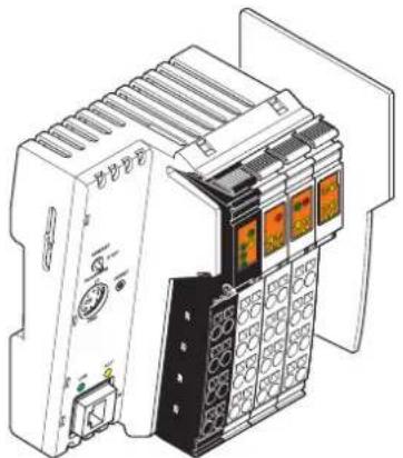
natural_image
Technical line drawing of an industrial control unit with multiple modules and a power outlet (no text or symbols visible)Figure 4-12 Example of an Inline Controller: ILC 151 ETH

For more detailed information, please refer to the terminal-specific data sheets and user manuals.
4.2.11 Branch terminals
4.2.11.1 Branch terminal for integrating a Fieldline Modular local bus in an Inline station
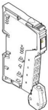
natural_image
Technical line drawing of an electrical fuse or socket component (no text or symbols visible)Figure 4-13 Example of a branch terminal: IB IL 24 FLM-PAC
These branch terminals can be used to integrate sensors and actuators in close proximity to the station, which are connected to the Fieldline Modular M8 or M12 local bus with IP65/67 protection, in your bus system.
The terminal converts the physical transmission method of the Inline local bus to the physical transmission method of the Fieldline Modular local bus.

For additional information, please refer to the terminal-specific data sheet and the documentation for Fieldline Modular.
4.2.11.2 Local bus extension (jumping between two rows)
An Inline station can be extended by one or more rows. A combination of an IB IL 24 FLM-PAC branch terminal and an IB IL 24 LSKIP-PAC local bus extension terminal is used for this.
The branch terminal is installed at the end of a row of an Inline station and the local bus extension terminal is installed at the start of the following row.
The data is transmitted between the two terminals via the RS-422 protocol.
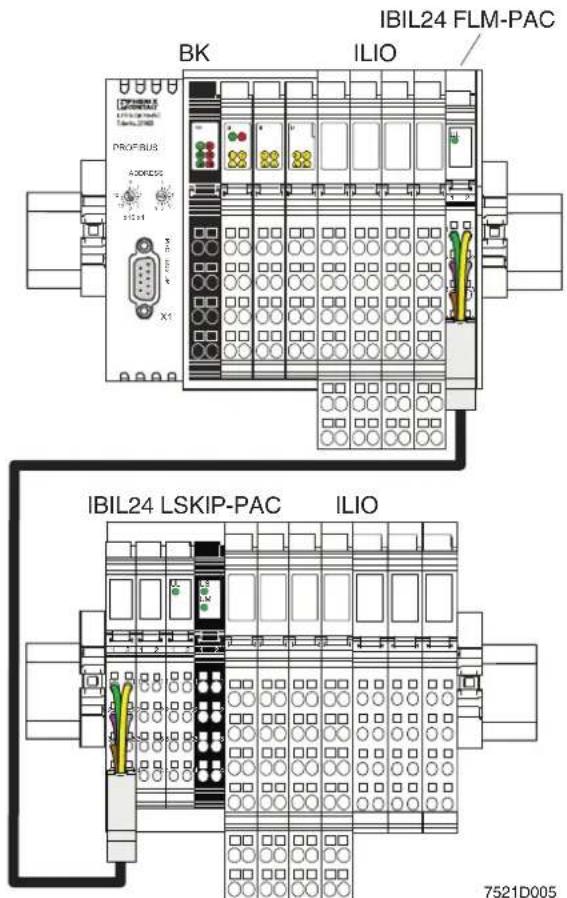
Figure 4-14 Example: Jumping between two rows within an Inline station
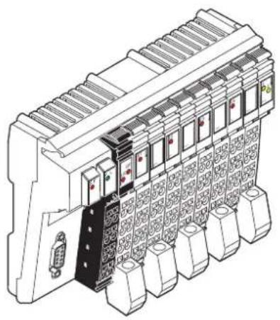
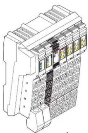
4.2.12 Typical structure of an Inline Modular IO station
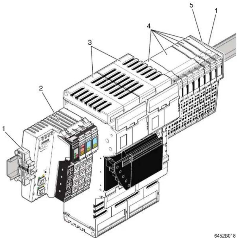
Figure 4-15 Example station with power-level terminals and 24 V DC terminals
The example Inline station shown in Figure 4-15 consists of the following elements:
1 End clamps
2 Bus coupler (example)
3 Power-level terminals
4 Terminals for the 24 V DC area (e.g., I/O terminal)
5 End plate (end of the station)
4.3 Inline Block IO modules
Block IO modules are available for inputting and/or outputting digital and analog signals to various bus systems (see Table 4-1).
natural_image
Technical line drawing of an industrial control unit with multiple modules and a central connector (no text or symbols visible)Module for PROFIBUS with four analog inputs and two analog outputs: ILB PB AI4 AO2
natural_image
Technical line drawing of a mechanical device with grid patterns and mounting brackets (no text or symbols)Module for INTERBUS with 16 digital inputs: ILB IB 24 DI16
Figure 4-16 Example: Modules of the Inline Block IO product range
| Scope of supply | Inline Block IO modules are available as complete items. The following are supplied as standard with a complete item:– The electronics base– All required Inline connectors |
| Bus system | Inline Block IO modules are available for various bus systems (see Table 4-1). |
| Power supply | All the required voltages are supplied at each individual Inline Block IO module. |
| Voltage areas | Inline Block IO modules are available for the 24 V DC voltage area. |
| Functions | Inline Block IO modules are available with various functions. These include the following modules, for example: The text in brackets indicates the function according to the order designation.– Digital input and output modules (DI, DO, DIO)– Analog input and output modules (AI, AO) |
| Protection | Overload protection of the system must be provided by the operator. The rating of the preconnected fuse must be such that the maximum load current is not exceeded. For the maximum permissible load current of an I/O module, please refer to the module-specific data sheet. |
| Grounding (FE) | All Inline Block IO modules have an FE spring (metal clip) on the bottom of the electronics base. This spring establishes an electrical connection to the DIN rail. Use grounding terminals to connect the DIN rail to protective earth ground. The module is grounded when it is snapped onto the DIN rail.To ensure reliable functional earth grounding of the module even when the DIN rail is dirty or the metal clip is damaged, Phoenix Contact also recommends grounding the module via one of the FE terminal points of a power connector. |
| Shielding | Shield connectors are available for connecting shielded cables. |
| Parameterization | Some modules can be parameterized via process data or PCP. For detailed information, please refer to the module-specific data sheet. |
| Data formats | The measured values and the corresponding output values of analog modules can be represented in different data formats depending on the module used and its configuration. These formats are listed in the relevant module-specific data sheets. |
| Diagnostics | The scope of the diagnostics depends on the module used and is specified in the relevant module-specific data sheet. |
| Additional documentation | |
| For more detailed information about the function, properties, wiring, and parameterization of the individual modules, please refer to the module-specific documentation. |
5 Structure and dimensions
5.1 Structure and dimensions of Inline Modular IO terminals
5.1.1 Basic structure of terminals in the 24 V DC and 120 V AC/230 V AC areas
Regardless of the function and design width, an Inline terminal for these voltage areas consists of the electronics base and the snap-on connector (Inline connector).
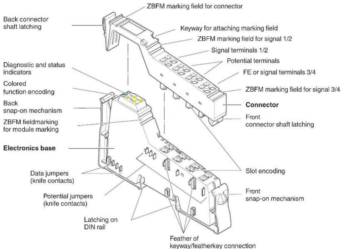
Figure 5-1 Basic structure of an Inline Modular IO terminal
ZBFM: Zack marker sheets, flat
(See also Section "Function identification and labeling" on page 53)

The components required for labeling are listed in the Phoenix Contact catalog.
5.1.2 Electronics base
| The electronics base holds the entire electronics for an Inline terminal and the potential and data routing. | |
| Potential and data routing | Potential and data routing are located in the base. As all terminals are snapped onto the DIN rail, the position of the interfaces between the terminals in relation to the DIN rail is the same for all terminals. The advantage of this is that terminals of different sizes can be integrated into the station.The knife contacts are located on the left-hand side of the terminal (shown in Figure 5-1). They snap into the featherkeys of the next terminal on the left when the station is mounted.The type of routing contacts (i.e., potential or data) that are on each terminal depends on the function of the terminal and is shown in the circuit diagram of the relevant terminal-specific data sheet. |
| Snap-on mechanism/latching | Pressing the front and back snap-on mechanism at the same time releases the latching, enabling the terminal to be removed by pulling it straight back from the DIN rail (see Section “Basic information about mounting” on page 100). |
| Keyway/featherkey connection | The featherkeys are on the left-hand side of the terminal (Figure 5-1). They snap into the keyways of the next terminal on the left when the terminal is mounted on the DIN rail. The featherkeys are also referred to as locking clips and the keyways as guideways. |
| Base colors | The base and the appropriate connectors for the different voltage areas are of different colors (see Section “Electronics base and connectors for the different voltage areas” on page 19). |
5.1.3 Connectors for terminals in the 24 V DC and 120 V AC/230 V AC areas
The I/O or supply voltages are connected using a pluggable connector. For more detailed information about the Inline connectors, please refer to Section 6, "Inline connectors".
5.1.4 Basic structure of power-level terminals
Power-level terminals are located in a power housing.
The power housing consists of the following parts:
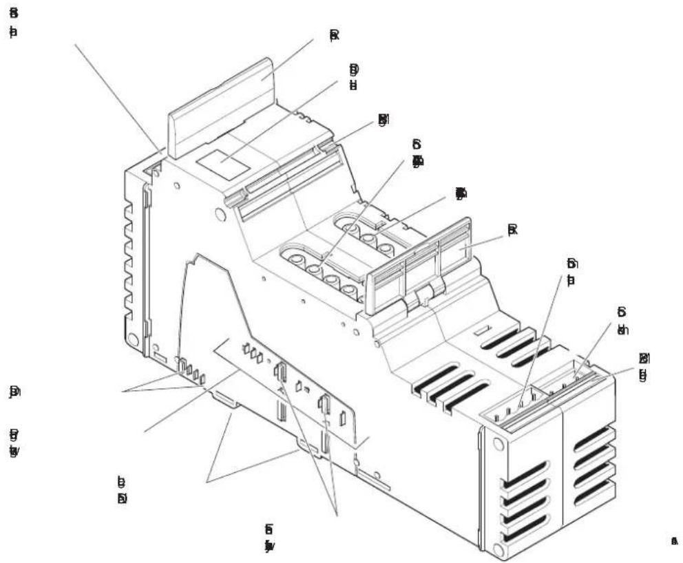
Figure 5-2 Basic structure of Inline housing for power-level terminals
ZBFM: Zack marker sheets, flat
(See also Section "Function identification and labeling" on page 53)

The components required for labeling are listed in the Phoenix Contact catalog.
| The entire electronics for the Inline power-level terminal, the potential routing for the 24 V DC area, and the data routing are located in the power housing. | ||
| Potential and data routing | The potential and data jumpers that are led through the 24 V DC terminals are not interrupted by the power-level terminals. For more detailed information about the jumpers, please refer to Section “Electrical potential and data routing (Inline Modular IO)” on page 73. | |
| Release flaps | Remove the power-level terminal from the DIN rail by pulling both release flaps (see Section “Mounting/removing power-level terminals” on page 117). | |
| Keyway/featherkey connection | The featherkeys are on the left-hand side of the terminal (Figure 5-2). They snap into the keyways of the next terminal on the left when the terminal is mounted on the DIN rail. | |
| 5.1.5 Connectors for power-level terminals | ||
| The mains voltage, motor output, brake module, hand-held operator panel mode, and the enable power level/24 V isolation functions are connected via connectors. | ||
| Power connector/ power bridge/ cover | A power connector is available for supplying the mains voltage (IB IL 400 CN-PWR-IN).A power bridge is available for forwarding the mains voltage between power-level terminals (IB IL 400 CN-BRG).A cover is available for covering unused connections for the 400 V mains connection of the Inline power-level terminals (IB IL 400 CN-COV). | |
 |   | |
| Figure 5-3 Power connector, power bridge, and cover | ||
| Other connectors | All other connectors are connected using COMBICON or MINI-COMBICON connectors (see Phoenix Contact catalog). | |
5.1.6 Function identification and labeling
Housing
The basic fields of application for Inline Modular IO terminals can be identified by their housing type or color.
Table 5-1 Field of application and housing
| Housing type Housing color Connector | color | Field of application | ||
| Low-level signal housing | Green | Green | Low-level signal (24 V DC) | All functions except supply, safety, DALI |
| Black | Low-level signal (24 V DC) | Supply, segmentation | ||
| Yellow | Yellow | Low-level signal (24 V DC) | Safety | |
| Gray | Gray | Low-level signal (24 V DC) | DALI | |
| Low voltage (120 V AC/230 V AC) | I/O, supply | |||
| Power housing | Green | Power | ||
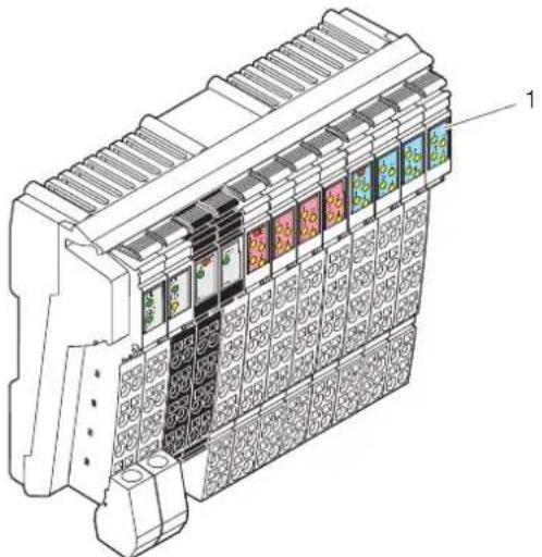
Function identification
The area for the diagnostic and status indicators on the terminals is color-coded to enable visual identification of the functions (1 in Figure 5-4).
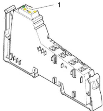
natural_image
Technical line drawing of a mechanical component with no visible text or symbolsFigure 5-4 Function identification
The following colors indicate the functions:
Table 5-2 Color-coding of terminal function
| Color | Terminal function |
| Gray | Bus couplers, terminals with remote bus branch |
| 24 V DC area | |
| Black | Supply/segmentation |
| Light blue, blue | Digital input |
| Pink, red | Digital output |
| Light green, green | Analog input, temperature recording |
| Light yellow, yellow | Analog output |
| Orange | Open and closed-loop control, communication, position detection, programmable terminals |
Table 5-2 Color-coding of terminal function
| Color Terminal function | |
| 120 V AC/230 V AC area | |
| White Distance | |
| White with lightning bolt Supply | |
| Dark blue with lightning bolt Digital input | |
| Dark red with lightning bolt Digital output | |
Identification of transmission speed
Terminals with a transmission speed of 500 kbps have solid color-coding.
Terminals with a transmission speed of 2 Mbps are identified by a white stripe at the level of the D LED.
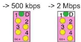
Figure 5-5 Identification of transmission speed
5.1.7 Housing dimensions of terminals in the 24 V DC and 120 V AC/230 V AC areas
Today, small I/O stations are frequently installed in 80 mm standard control boxes. Inline terminals are designed so that they can be used in this type of control box.
The terminal housing dimensions are determined by the dimensions of the electronics base and the dimensions of the connector.
The width of the terminal depends on the electronics base used (housing).
When a connector is plugged in, each terminal has a depth of 72 mm.
The height of the terminal depends on the connector used and is a maximum of 141 mm.
For the dimensions of the terminals, please refer to the relevant terminal-specific data sheet.
5.1.7.1 Dimensions of the electronics base with possible connectors
BK housing, example: IL CO BK-PAC
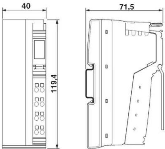
Figure 5-6 Dimensions of BK housing (in mm)
BK IO housing, example: IL xx BK DI8 DO4 2TX-PAC ILC 150 ETH
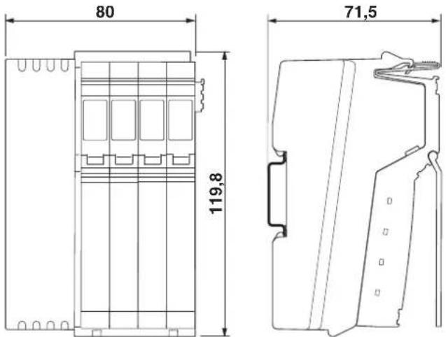
Figure 5-7 Dimensions of BK IO housing (in mm)
Container housing, example:
IBS IL 24 BK-LK-PAC
IL PB DP/V1-PAC
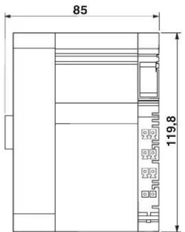
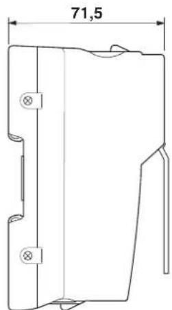
Figure 5-8 Dimensions of the electronics base (container housing 1, in mm)
Container housing, example:
ILC 3xx ...
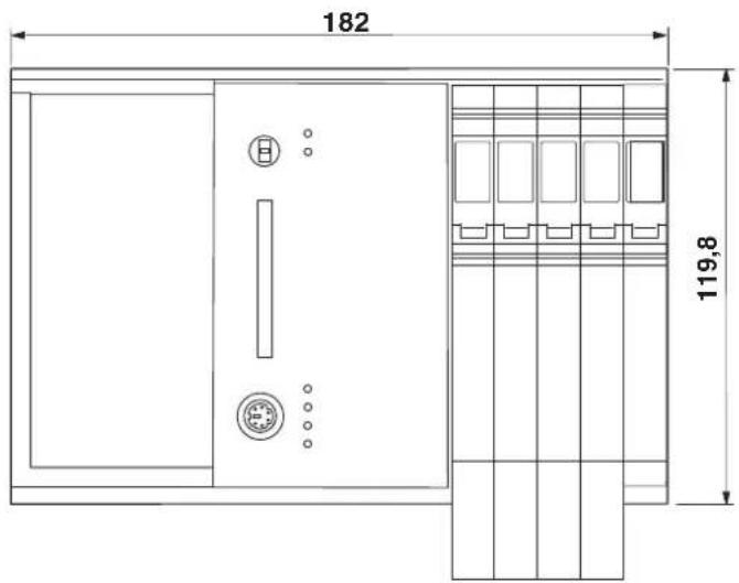
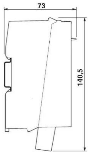
Figure 5-9 Dimensions of container housing 4 (in mm)
Container housing, example:
ILC 200 IB
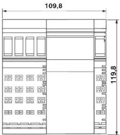
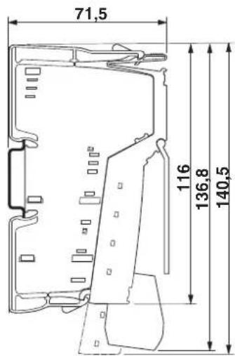
Figure 5-10 Dimensions of container housing 3 (in mm)
Dimensions of 2-slot, 4-slot, 8-slot housing
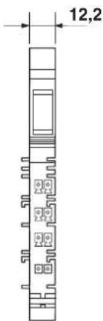
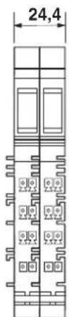
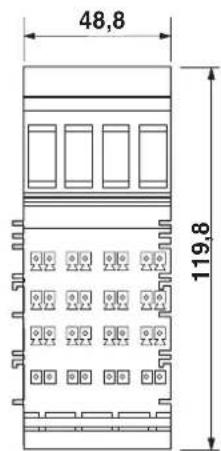
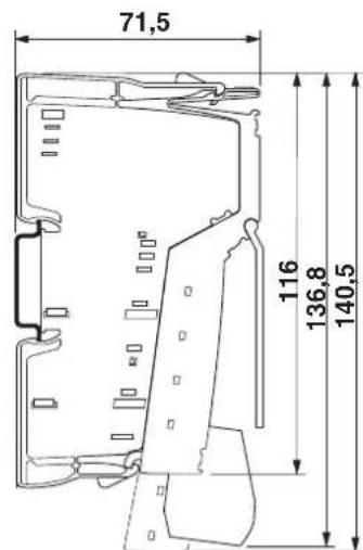
Figure 5-11 Dimensions of the electronics base with possible connectors (2-slot, 4-slot, 8-slot housing, in mm)
Examples for 2-slot, 4-slot or 8-slot housing:
2-slot housing 4-slot housing 8-slot housing
IB IL 24 DO 2-PAC IB IL AO 1/SF-PAC IB IL 24 DO 8-PAC
IB IL 24 DI 4-PAC IB IL CNT-PAC IB IL 24 DI 16-PAC
These bases take one, two or four 12.2 mm wide connectors.
Container housing, example:
ASI MA IB IL
IB IL 24 SAFE 1-PAC
ILC 200 UNI
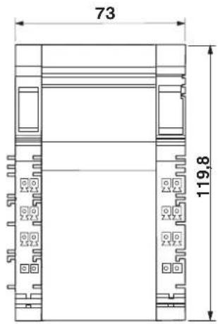
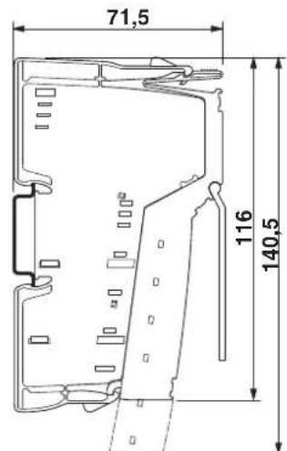
Figure 5-12 Dimensions of container housing 2 (in mm)
5.1.8 Dimensions of power-level terminals
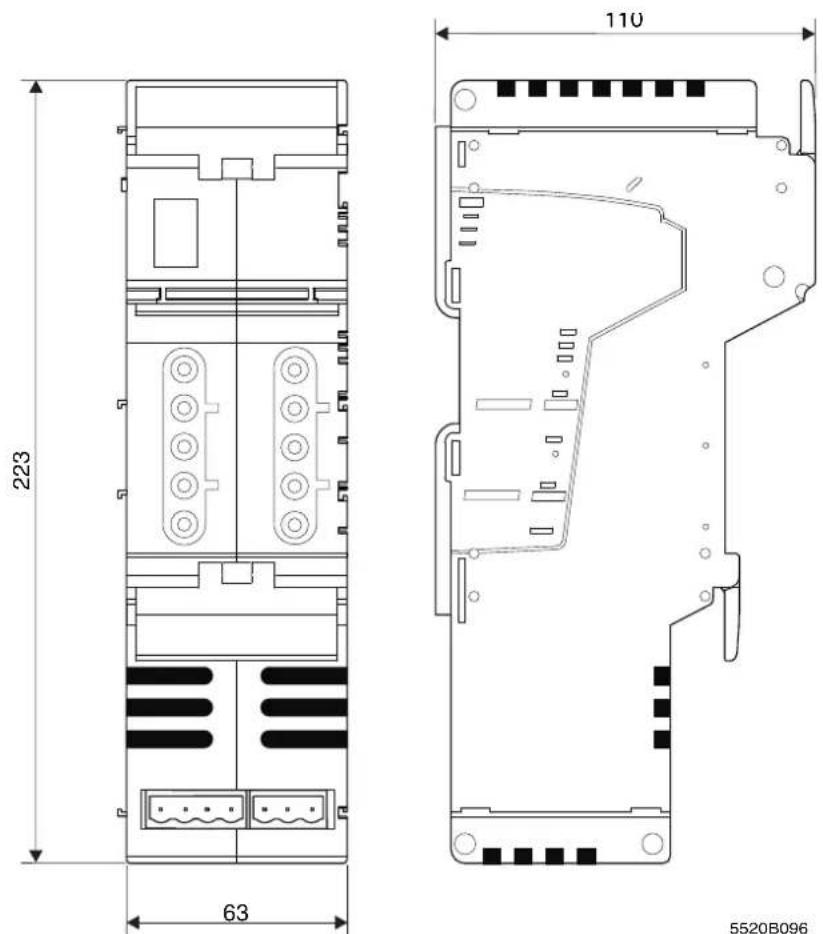
Figure 5-13 Dimensions of power housing

Please note the additional space required when inserting a connector for a hand-held operator panel.
5.2 Structure and dimensions of Inline Block IO modules
5.2.1 Basic structure of modules
Regardless of the function, an Inline Block IO module consists of the electronic module and the snap-on connectors (Inline connectors).
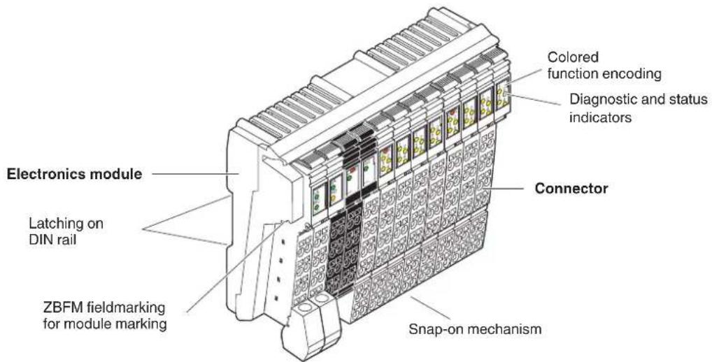
Figure 5-14 Basic structure of an Inline Block IO module
ZBFM: Zack marker sheets, flat
(See also Section "Function identification and labeling" on page 53)

The components required for labeling are listed in the Phoenix Contact catalog.
Electronic module
The electronic module holds the entire electronics for an Inline Block IO module.
Pressing the snap-on mechanism releases the latching, enabling the terminal to be removed by pulling it straight back from the DIN rail (see Section "Basic information about mounting" on page 100).
Connector
The I/O or supply voltages are connected using a pluggable connector. For more detailed information about the Inline connectors, please refer to Section 6, "Inline connectors".
5.2.2 Function identification and labeling
Housing
Apart from their width, Inline Block IO modules have the same appearance in terms of their housing type and housing color (green).
Function identification
The Inline Block IO modules are color-coded to enable visual identification of the function areas (1 in Figure 5-15).
natural_image
Technical line drawing of a mechanical device with multiple panel slots and decorative patterns (no text or symbols)Figure 5-15 Function identification
The following colors indicate the functions:
Table 5-3 Color-coding of module function areas
| Color Module function area | |
| Gray Bus/supply | |
| Light blue Digital input | |
| Pink Digital output | |
| Purple Digital input or output | |
| Green Analog input | |
| Yellow Analog output |
5.2.3 Housing dimensions
Today, small I/O stations are frequently installed in 80 mm standard control boxes.
Inline Block IO modules are designed so that they can be used in this type of control box.
The terminal housing dimensions are determined by the dimensions of the electronic module and the dimensions of the connector.
The width of the electronic modules depends on the function and is either 95 mm or 156 mm.
When a connector is plugged in, each terminal has a depth of 55 mm.
The height of the terminal depends on the connector used and is a maximum of 141 mm.
For the dimensions of the modules, please refer to the relevant module-specific data sheet.
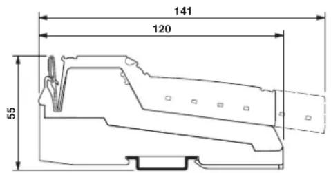
Figure 5-16 Maximum dimensions (dimensions in mm)
6 Inline connectors
Inline connectors are used on Inline Modular IO terminals and Inline Block IO modules.
6.1 Basic structure and dimensions of Inline connectors
Connector width The connectors have a width of two terminal points.
Connector colors
To distinguish between the functions and voltage areas, the connectors have been assigned different colors:
Green Connectors for low-level signal terminals (24 V DC, excluding power/segment terminals)
Black Connectors for low-level signal power/segment terminals (24 V DC)
Gray Connectors for terminals in the 120 V AC and 230 V AC areas (not required for Inline Block IO modules)
Basic structure
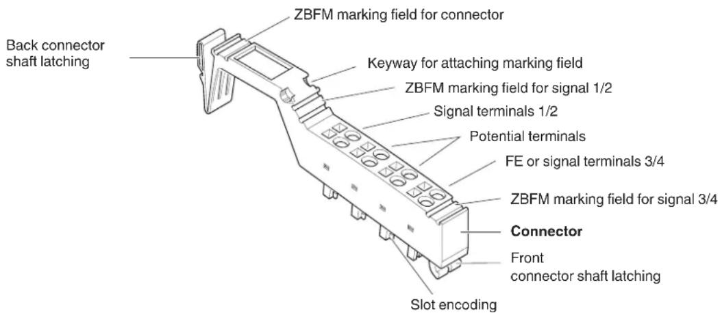
Figure 6-1 Basic structure of an Inline connector
ZBFM: Zack marker sheets, flat
(See also Section "Function identification and labeling" on page 53)

The components required for labeling are listed in the Phoenix Contact catalog.
Dimensions
A
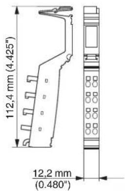
B
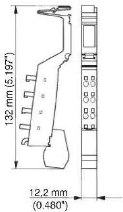
C
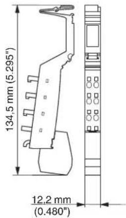
D
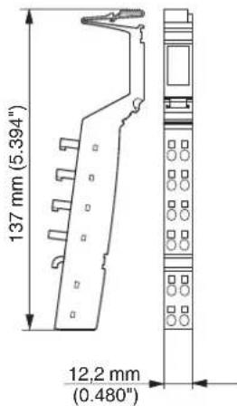
Figure 6-2 Connector dimensions
Key:
A S t a n d a r d c o n n e c t
B Shield connector for connecting one cable
C Shield connector for connecting two cables
D Extended double signal connector
The depth of the connector does not influence the overall depth of the Inline Modular IO terminal or Inline Block IO module.
6.2 Connectors for the 24 V DC area
Connector types
The following connector types are available for the 24 V DC area:
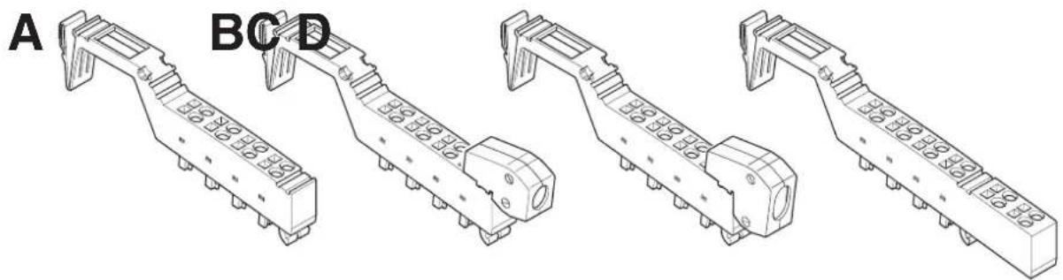
natural_image
Technical line drawings of four mechanical components labeled A, B, C, D (no text or symbols on the parts themselves)Figure 6-3 Connector types for Inline terminals
A S t a n d a r d c o n n e c t
The green standard connector is used for the connection of two signals in 4-wire technology or 8 signals in 1-wire technology (e.g., digital I/O signals).
The black standard connector is used to supply the supply voltage. Some of the adjacent contacts can be jumpered internally (see Figure 6-4 on page 66).
B Shield connector for connecting one cable
C Shield connector for connecting two cables
Green connectors B and C are used for signals connected using shielded cables (e.g., analog I/O signals, high-frequency counter inputs, remote bus cable).
FE or shielding is connected via a shield connection clamp rather than via a terminal point.
D Extended double signal connector
The green double signal connector is used for the connection of four signals in 3-wire technology (e.g., digital I/O signals).
The black double signal connector is used to supply the supply voltage. Some of the adjacent contacts can be jumpered internally (see Figure 6-4 on page 66).
Connector identification
All connectors are available with and without color print. The connectors with color print (indicated with CP in the order designation) have terminal points that are color-coded according to their functions. The following colors indicate the signals of the terminal points:
Table 6-1 Color-coding of terminal points (24 V DC)
| Color Signal at terminal point | |
| Red + | |
| Blue - | |
| Green Functional earth ground (FE) | |
| Green/yellow Functional earth ground (FE);This marking may still be seen on older connectors. Functional earth ground is marked in green on modern connectors. | |
Internal jumpering

Depending on their function, the connectors may support internal jumpering.
NOTE: Disregarding this warning may result in malfunction
To avoid malfunction, only snap the connector onto an appropriate terminal. Refer to the relevant terminal-specific data sheet to select the correct connectors.
Only place black connectors on power or segment terminals.
When the terminal points are jumpered in the black connector, potential is routed through the jumpering in the connector and not through the printed circuit board of the terminal.
The complete current carrying capacity is ensured through this jumpering.
A black connector must not be placed on a terminal that is to be used for a double signal connector. Incorrect connection may lead to a short circuit between two signal terminal points.
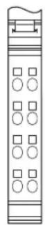


natural_image
Vertical diagram with grid patterns and a labeled section 'D' (no text or symbols within the diagram itself)
natural_image
Pure electrical circuit lines without any symbols
natural_image
Pure electrical circuit lines without any symbolsFigure 6-4 Internal jumpering in connectors for the 24 V DC area
A Green connector for connecting the I/O
B Black connector for supplying the supply voltages with jumpering of the terminal points for power supply
C Black connector for supplying the supply voltages without jumpering of the terminal points for power supply
D Green shield connector for connecting shielded cables; the terminal points are jumpered via the shield connection.
E Green double signal connector for connecting the I/O
F Black connector for supplying the supply voltages with jumpering of the terminal points for power supply
The shield connector is jumpered between terminal points 1.4 and 2.4 through the shield connection as seen in Figure 6-4. All other connectors are jumpered internally through the terminal point connections in the connector.
6.3 Connectors for the 120 V AC/230 V AC area (Inline Modular IO)
Connector types
Gray standard connectors (see A in Figure 6-4) are available for the 120 V AC and 230 V AC areas. They have different color print according to their function.
Special features
The special features of the connectors and base for the 120 V AC and 230 V AC areas are described in Section “Electronics base and connectors for the different voltage areas” on page 19.
Table 6-2 Color-coding of terminal points (120 V AC/230 V AC)
| Color Signal at terminal point | |
| Black Phase (L) | |
| Blue Neutral conductor (N) | |
| Green/yellow Protective earth ground (PE) |

The connectors for terminals used to isolate different voltage areas are color-coded with two colors. This includes connectors for power terminals and end terminals for the 120 V AC and 230 V AC areas, as well as distance terminals.
The green marked side must point in the direction of the 24 V area and the gray marked side in the direction of the AC area.
Internal jumpering and special features of the terminal points
Depending on their function, the connectors may support internal jumpering. In addition, some terminal points are not used or are indeed closed.

NOTE: Disregarding this warning may result in malfunction
To avoid malfunction, only snap the connector onto an appropriate terminal. Refer to the relevant terminal-specific data sheet to select the correct connectors.
A
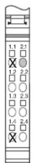
B
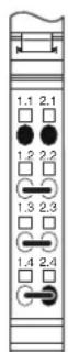
C

D
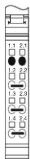
E
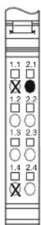
Figure 6-5 Internal jumpering and special features of connectors for the 120 V AC/230 V AC area
X Connector contact not present

Terminal point without metal contact

Terminal point closed
A Gray connector for plugging onto the left-hand side of a power terminal (start of the AC area)
B Gray connector for supplying the supply voltage
C Gray connector for connecting the I/O
D Gray connector for connecting the cables to a relay terminal
E Gray connector for plugging onto an end terminal
6.4 Numbering and labeling of terminal points
Labeling/terminal numbering
Terminal point numbering is explained using the example of an 8-slot Inline Modular IO terminal.
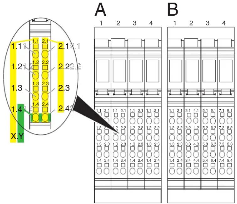
Figure 6-6 Terminal point numbering
Slot/connector
The slots (connectors) on a base are numbered consecutively. This numbering is not indicated on the terminal (shown above the terminals in Figure 6-6).
Terminal point
Connectors are available with different forms of marking. In general, the numbering format X.Y is marked above the terminal point.
1 Terminal point numbering by connector (detail A in Figure 6-6):
On these connectors:
X: Number of the terminal point column on the connector.
Y: Number of the terminal point within the terminal point column.
2 Terminal point numbering by channel (detail B in Figure 6-6):
For terminals with 8, 16 or 32 I/Os, connector sets are available in which the terminal point rows are numbered by terminal (1 to 8) rather than by connector (1 and 2).
X: Number of the terminal point column on the Inline terminal.
Y: Number of the terminal point within the terminal point column.

Select the necessary connectors from the Phoenix Contact catalog.
Additional labeling
In addition to this connector marking, you can identify the slots, terminal points, and connections using Zack marker strips and labeling fields.
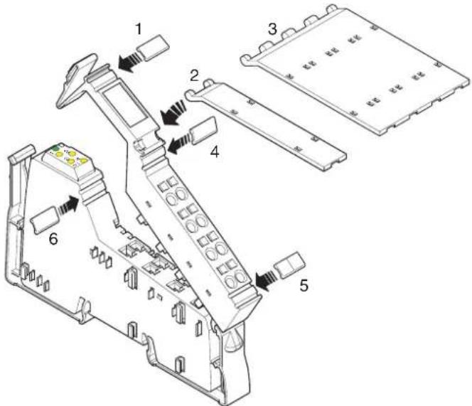
Figure 6-7 Labeling
Various options are available for labeling the slots and terminal points:
1 Each connector can be labeled individually using Zack marker strips. 2/3 Another option is to use a labeling field. Labeling fields are available in two widths, either as a labeling field covering one connector (2; IB IL FIELD 2) or as a labeling field covering four connectors (3; IB IL FIELD 8). You can label each channel individually with free text. On the upper part of the connector there is a keyway for attaching this labeling field. The labeling field can be tilted up and down. In each end position a light latching ensures that the labeling field remains in place.
4/5 Each signal can be labeled individually using Zack marker strips. On a double signal connector, the upper keyway (4) is designed for labeling signals 1 and 2 and the lower keyway (5) is for signals 3 and 4.
6 On the electronics base, each slot can be labeled individually using Zack marker strips. These marker strips are covered when a connector is plugged in.
Using the marker strips on the connector and on the electronics base, you can clearly assign both connector and slot.
Insert strips for use with a laser printer are available for insertion in the IB IL FIELD 2 and IB IL FIELD 8 labeling fields (see Section "Ordering data for accessories" on page 153).

The components required for labeling are listed in the Phoenix Contact catalog.
6.5 Terminal point keying
In order to prevent connectors being mixed up, the connection points between connectors and terminals can be keyed using the IL CP keying profile.
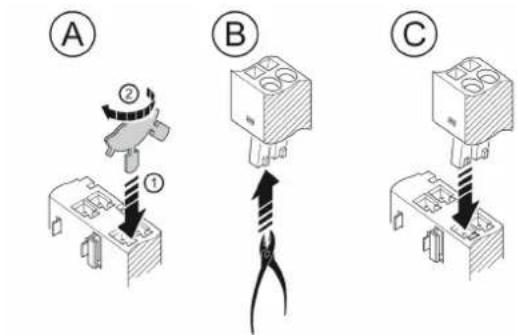
Figure 6-8 Connector and terminal keying
A 1. Insert a keying section of the keying profile in the corresponding keyway of the terminal point on the electronic housing.
- Twist the keying profile to break off the keying section.
B Remove the keying tab from the corresponding slot keying on the connector.
C Insert the keyed connector in the corresponding slot.
7 Electrical potential and data routing (Inline Modular IO)

The Project+ software provides support when configuring an Inline station (see Section "Appendix: Software support" on page 169).
7.1 Circuits and provision of supply voltages
There are several circuits within an Inline station. These are automatically created when the terminals are properly installed. The voltages of the different circuits are supplied to the connected terminals via potential jumpers.
An example of the circuits within an Inline station is given in Section "Example of a circuit diagram" on page 78. The descriptions in the following sections refer to this example.

Please refer to the terminal-specific data sheet for the circuit to which the I/O circuit of a specific terminal is to be connected.
Carrying capacity of the jumper contacts
Observe the maximum current carrying capacity of the jumper contacts on the side for each circuit. The current carrying capacities for all potential jumpers are given in the following sections and are summarized in Section "Current and voltage distribution" on page 84.
For the arrangement of the potential jumpers and information about current and voltage distribution on the potential jumpers, please refer to Section “Electrical potential and data routing” on page 80.
The connection of the supply voltages is described in Section “Connecting the power supplies” on page 128.

For voltage connection, please observe the notes in the terminal-specific data sheets.
7.1.1 Bus coupler supply

Please refer to the documentation for your bus coupler to determine the correct supply voltage for the bus coupler.
The voltages for the logic circuit U_L and the supply of the terminals for analog signals U_ANA are always internally generated from the bus coupler supply.
7.1.2 Logic circuit
The logic circuit with the communications power U_L starts at the bus coupler or at a power terminal (IB IL 24 PWR IN/R-PAC; IB IL 24 PWR IN/PS-PAC) and is led through all the terminals of an Inline station.
Function The logic circuit (e.g., protocol chip, microcontroller) of the devices in a station is supplied with voltage from the logic circuit.
Voltage The voltage in this circuit is 7.5 V DC ±5%.
Provision of U_L The communications power U_L is provided by the bus coupler or a corresponding power terminal from the connected supply voltage.
Current carrying capacity The maximum current carrying capacity is 2 A. If this value is reached, the voltage must be boosted via a power terminal or a new station must be created using a bus coupler.
The current consumption from the logic circuit of each device is specified in the DB GB IB IL DEVICE LIST data sheet and the relevant terminal-specific data sheet.
The communications power is not electrically isolated from the 24 V DC input voltage for the bus coupler.

This maximum current carrying capacity can be limited by certain bus couplers or corresponding power terminals. Please refer to the information in the terminal-specific data sheets.
7.1.3 Analog circuit
The analog circuit with the supply for the analog terminals (also referred to as analog voltage) U_ANA starts at the bus coupler or at a power terminal (IB IL 24 PWR IN/R-PAC; IB IL 24 PWR IN/PS-PAC) and is led through all the terminals of an Inline station.
Function The I/O for analog signal terminals is supplied from the analog circuit.
Voltage The voltage in this circuit is 24 V DC (+20%, -15%).
Provision of U_ANA The analog voltage U_ANA is provided by the bus coupler or a corresponding power terminal from the connected supply voltage.
Current carrying capacity The maximum current carrying capacity is 0.5 A. If this value is reached, the voltage must be boosted via a power terminal or a new station must be created using a bus coupler.
The current consumption from the analog circuit of each device that is supplied from U_ANA is specified in the DB GB IB IL DEVICE LIST data sheet and the relevant terminal-specific data sheet.
7.1.4 Main circuit
The main circuit with the main voltage U_M starts at the bus coupler or a power terminal and is led through subsequent terminals until it reaches the next power terminal.

Please note the special requirements of Inline terminals with relay outputs. These terminals interrupt the potential jumpers U_M and U_S .
A new circuit starts at the next power terminal. This circuit is electrically isolated from the previous one if electrically isolated power supply units are used.
Several power terminals can be used within one station.
Function The segment voltage U
U_S can be tapped from the main voltage U_M using different segment terminals. Several independent segments can thus be created within the main circuit. The main circuit provides the supply voltage for these segments.
Some terminals access the main circuit directly. For example, the encoder supply for positioning terminals is tapped from the main circuit, while the I/O is supplied from the segment circuit.
Voltage The voltage in this circuit must not exceed 30 V DC.
Current carrying capacity
The maximum current carrying capacity for the main circuit is 8 A (total current with the segment circuit).

This maximum current carrying capacity can be limited by certain terminals. Please refer to the information in the terminal-specific data sheets.
If the limit value of the potential jumpers U_M and U_S is reached (total current of U_S and U_M ), a new power terminal must be used.
Provision of U_M
In the simplest case, the main voltage U_M can be supplied at the bus coupler.
The main voltage U_M can also be supplied via a power terminal. A power terminal must be used if:
1 A bus coupler that cannot supply the main voltage is used.
2 Different voltage areas (e.g., 24 V DC and 120 V AC) are to be created.
3 Electrical isolation between different I/O areas is to be created.
4 The maximum current carrying capacity of the potential jumpers U_M , U_S , and GND (total current of U_S and U_M ) is reached.
7.1.5 Segment circuit
The segment circuit with segment voltage U_S starts at the bus coupler or a power or segment terminal and is led through the subsequent terminals until it reaches the next power or segment terminal.

Please note the special requirements of Inline terminals with relay output. These terminals interrupt the potential jumpers U_M and U_S .
You can use several segment terminals within a main circuit and therefore segment the main circuit.
Function
Almost all the terminals in the Inline station except the analog terminals are supplied from the segment circuit (e.g., digital input terminals, digital output terminals).
The segment circuit also provides the auxiliary voltage for controlling circuit breakers and contactors.
Some terminals access both the segment circuit and the main circuit. For example, the encoder supply for positioning terminals is tapped from the main circuit, while the I/O is supplied from the segment circuit.
The segment circuit can be switched off or fused using the safety or segment terminals. It has the same reference ground as the main circuit. This means that circuits with different fuses can be created within the station without external cross-wiring.
Voltage The voltage in this circuit must not exceed 30 V DC.
Current carrying capacity
The maximum current carrying capacity for the segment circuit is 8 A (total current with the main circuit).

This maximum current carrying capacity can be limited by certain terminals. Please refer to the information in the terminal-specific data sheets.
If the limit value of the potential jumpers U_M and U_S is reached (total current of U_S and U_M ), a new power terminal must be used.
Provision of U_S
There are various ways of providing the segment voltage U_S :
1 The segment voltage can be supplied at the bus coupler or a power terminal.
2 The segment voltage can be tapped from the main voltage at the bus coupler or a power terminal using a jumper or a switch.
3 An IB IL 24 PWR IN/2-F...-PAC power terminal with fuse for the main and segment circuit or a segment terminal with fuse for the segment circuit can be used. In these terminals the segment voltage is automatically tapped from the main voltage.
4 A segment terminal can be used without a fuse and the segment voltage can be tapped from the main voltage using a jumper or a switch.

The creation of segments is not possible for the 120 V AC and 230 V AC voltage levels. Here, only one circuit is used, which corresponds to the main circuit.
7.1.6 Mains voltage for power-level terminals
The mains voltage for power-level terminals is not provided via the potential jumpers. It is either supplied to the power-level terminal via a power connector or led between directly adjacent power-level terminals via power bridges.
Voltage The mains voltage must have the following values:
IB IL 400 ELR ... IB IL 400 MLR ...
Nominal voltage during operation (conductor voltage) 400 V AC 400 V AC
Voltage range 187 V AC ... 440 V AC + 0% with safe isolation between mains and SELV 187 V AC ... 519 V AC + 0% with safe isolation between mains and SELV;
187 V AC ... 600 V AC + 0% with basic insulation between mains and SELV
Frequency The frequency of the mains voltage must be 50 Hz or 60 Hz.
Current carrying capacity The maximum current carrying capacity for the incoming mains must be 20 A. If this value is reached, it must be reinjected.
7.1.7 Example of a circuit diagram
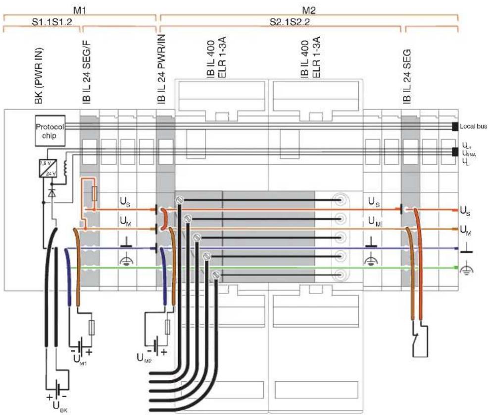
Figure 7-1 Potential routing within an Inline station
The illustrated Inline station is a typical example. It shows the supply and provision of different voltages and their forwarding via potential jumpers. Explanations for this can be found in the following sections.
Mx Main circuit (e.g., M1, M2)
Sx,y Segment circuit y in main circuit x (e.g., S2.1, S2.2)
BK (PWR IN) Bus coupler in conjunction with a power terminal, if required
| U_BK | Bus coupler supply (supply for bus coupler, generates U_ANA and U_L ) |
| U_M | Main supply (I/O supply in the main circuit) |
| U_S | Segment supply (I/O supply in the segment circuit) |
| U_ANA | I/O supply for analog terminals |
| U_L | Communications power |
Local bus Data jumper for the local bus
⊥
Ground (GND for the supply voltages U_M and U_S )


Noiseless ground (functional earth ground, FE)
Protective earth ground
I Indicates the interruption of a potential jumper
Main circuit M1/segment S1.1
The supply voltage for the bus coupler U_BK is supplied at the bus coupler (BK). In addition, the main voltage U_M1 is supplied at the bus coupler or a subsequent power terminal.
The communications power U_L and the supply voltage for the analog terminals U_ANA are generated from the bus coupler supply and led through the entire station.
Electrical isolation between logic and I/O is created through the separate supply of the bus coupler supply U_BK and the main voltage U_M1 .

If these voltages are not supplied separately (e.g., only the voltage U_M1 , from which U_L and U_ANA are also generated), there is no electrical isolation between logic and I/O.
No terminals are used in segment S1.1.
Segment S1.2 In a segment terminal with fuse, the segment voltage U S for segment S1.2 is automatically tapped from the main voltage U M1 . This segment circuit is protected by the internal fuse.

This segment terminal has been specifically used to create a protected segment circuit without the need for an additional external fuse. If this is not necessary, the terminal does not have to be used. In this case, the connection between U_M and U_S on the bus coupler must be established using a jumper (as shown on the IB IL 24 PWR/IN-PAC terminal) or a switch (as shown on the IB IL 24 SEG-PAC terminal).
Main circuit M2/segment S2.1
The supply voltage for the power-level terminals and the subsequent terminals should be supplied separately. For this, a new power terminal (e.g., IB IL 24 PWR/IN-PAC) is used, which supplies the supply voltage U_M2 .
Using a jumper, the segment voltage U_S for segment S2.1 is tapped from the main voltage U_M2 at this terminal.
Segment S2.2 The segment voltage U _S is provided at the IB IL 24 SEG-PAC segment terminal via a switch. Output terminals installed here can therefore be switched externally.
Examples of errors and their effects:
1 In this example structure, a short circuit in segment S1.2 would not affect the terminals in other segments. The fuse in the IB IL 24 SEG/F-PAC segment terminal means that only segment S1.2 is switched off.
2 If an error occurred in the system, the terminals in segment S2.2, for example, could be switched on or off without affecting the terminals in other segments.
7.2 Electrical potential and data routing
7.2.1 Arrangement of potential and data jumpers
An important feature of Inline is its internal potential routing system. The electric connection between the individual station devices is created automatically when the station is installed. When the individual station devices are connected, a power rail is created for the relevant circuit. Mechanically, this is created by interlocking knife and featherkey contacts from the adjacent terminals.
This potential routing eliminates the need for additional external potential routing or cross-wiring.

The 400 V AC mains voltage for power-level terminals is not led via the internal station potential routing. It is supplied via a power connector and is led between two power-level terminals via power bridges.
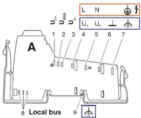
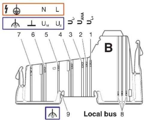
Figure 7-2 Basic arrangement of potential and data jumpers
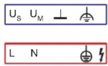
Potential jumper for the 24 V AC voltage area
Potential jumper for the 120 V AC and 230 V AC voltage areas
Table 7-1 Potential and data jumpers (24 V DC area)
| No. Function Meaning | |||
| See Figure 7-2 “Basic arrangement of potential and data jumpers” on page 80 | |||
| Potential jumpers | |||
| 1 | 7 . | _+ | Communications power for the bus interface |
| 2 | 2 4 | _AMA | I/O Supply for analog terminals |
| 3 | G N | _LD | Ground of communications power and I/O supply for analog terminals |
| 4 | 2 4 | _SV | Segment circuit supply(if necessary with overload protection) |
| 5 | 2 4 | _MV | Main circuit Supply U(if necessary with overload protection) |
| 6 GND | GND Ground of segment and main supply | ||
| 7 FE | FE | Functional earth ground | |
| (9) | FE spring | FE contact to the DIN rail(for bus couplers, segment terminals, and power terminals for the SELV area) | |
| Data jumper | |||
| 8 | Local bus | ||

Terminal inputs and outputs are supplied with voltage via the segment circuit.
The voltage for the segment circuit can be tapped from the main circuit. In addition, some terminals tap the voltage directly from the main circuit.
For more detailed information about the circuits that are created via the potential jumpers U_L , U_ANA , U_M , and U_S , please refer to page 73.

Depending on the terminal function, not all of the jumpers listed in Figure 7-2 are present on a terminal. Please refer to the circuit diagram of the terminal to see which jumpers are available for a terminal and how they are internally connected. The circuit diagram is shown in the terminal-specific data sheet.
GND
(24 V DC area)
This potential jumper is ground for the main and segment circuits.

NOTE: Overload
Please note that the GND potential jumper carries the total current of the main and segment circuits. The total current of the main and segment circuits must not exceed the maximum current carrying capacity of the potential jumpers (8 A). The maximum current carrying capacity is determined not only by the potential jumpers, but also by the power/segment terminal used.
Calculate the current in the station. Refer to the data provided in the terminal-specific data sheets for your particular application.

The Project+ software provides support when calculating the currents (see Section "Appendix: Software support" on page 169).
FE
(24 V DC area)
The FE potential jumper is connected to the grounded DIN rail via the FE spring at each bus coupler, each 24 V power terminal, and each segment terminal and is led through all subsequent 24 V terminals.
In addition, connect the FE connection to a grounding terminal at the bus coupler.
If the FE jumper is interrupted by a 120 V AC/230 V AC voltage level, reconnect the FE connection to a grounding terminal at the subsequent 24 V DC power terminal.

Please also observe the information in Section "Grounding concept" on page 106.
FE spring
(24 V DC area)
This spring creates the FE contact between the bus coupler, a 24 V DC power terminal or a segment terminal, and the grounded DIN rail.
Data routing
(all areas)
The bus signal is also transmitted within the station using a connection that is created automatically when the station devices are snapped on.
Current carrying capacity
(all areas)
The maximum total current flowing through the potential jumpers is limited. The maximum current carrying capacity for each circuit is specified in Section "Circuits and provision of supply voltages" on page 73.

Please also observe the information about the current carrying capacity of the power and segment terminals provided in the terminal-specific data sheets.

NOTE: Malfunctions
If the current carrying capacity of the potential jumpers U_L or U_ANA is reached, the voltage must be boosted via a power terminal, or a new station must be created using a bus coupler
If the current carrying capacity of the potential jumpers U_M, U_S , and GND is reached (total current of U_S and U_M ), a new power terminal must be used.

The Project+ software provides support when calculating the currents (see Section "Appendix: Software support" on page 169).
Table 7-2 Potential and data jumpers (120 V AC/230 V AC area)
| No. Function Meaning | |||
| See Figure 7-2 “Basic arrangement of potential and data jumpers” on page 80 | |||
| Potential jumpers | |||
| 1 | 7 . | _+ | Communications power for the bus interface |
| 2 | 2 4 | I/O supply for analog terminals | |
| 3 | G N | L.D | Ground of communications power and I/O supply for analog terminals |
| 4 120 V | AC/230 V AC | L1 Phase | L1 |
| 5 | 0 V | N | P E N c o n d uc to r |
| 6 – | Not present | ||
| 7 PE | PE Protective earth ground | ||
| (9) | – | Not present | |
| Data jumper | |||
| 8 | Local bus | ||

Depending on the terminal function, not all of the jumpers listed in Figure 7-2 are present on a terminal. Please refer to the circuit diagram of the terminal to see which jumpers are available for a terminal and how they are internally connected. The circuit diagram is shown in the terminal-specific data sheet.
PE (120 V AC/230 V AC area)
The PE potential jumper is used in the 120 V AC/230 V AC area. It must be connected to protective earth ground via the corresponding connection at the power terminal for these voltage areas.
7.2.2 Current and voltage distribution
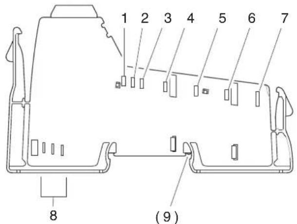
Figure 7-3 Current and voltage distribution
Table 7-3 Current and voltage distribution in potential and data jumpers (24 V DC)
| No. Function Voltage to contact | 1 | Current | |||
| Minimum Maximum Maximum | |||||
| Potential jumpers | |||||
| 1 | 7 . | _L-5 | 7.0V DC 7.87DV DC 2 A C | U | |
| 2 | 2 4 | _ANA | 19.2DV DC 30 VDC 0.5 A U | ||
| 3 | G N | _L- D | 0 VDC U | 0 V DC | 2.5 A |
| 4 | 2 4 | _S V | 19.2DV DC 30 VDC U | 8 A | |
| 5 | 2 4 | _M V | 19.2DV DC 30 VDC U | ||
| 6 | GND | GND | 0 V | 0 V | 8 A |
| 7 | FE | FE | Not defined | Not defined | Not defined |
| (9) | FE spring | ||||
| Data jumpers | |||||
| 8 a | Bus signal | ||||
| 8 b | Bus signal | ||||
| 8 c | Clock | ||||
Contact no. 3 is reference potential for the logic. Contact no. 6 is reference potential for the I/O. If there is no electrical isolation between logic and I/O, both have the same potential.
Table 7-4 Current and voltage distribution in potential and data jumpers (120 V AC/230 V AC)
| No. Function Voltage to contact | 1 | Current | |||
| Minimum Maximum Maximum | |||||
| Potential jumpers | |||||
| 1 | 7 . | L-5 | 7.0V DC 7.87V DC 2 A C | U | |
| 2 | 2 4 | ANA | 19.2V DC 30 VDC U | 0.5 A | |
| 3 | G N | L- D | 0 VIDC U | 0 V DC | 2.5 A |
| 4 | 120 V AC/230 V AC | L1 | 12 V AC | 253 V AC | 8 A |
| 5 | PEN conductor | N | 0 V | 0 V | 8 A |
| 6 | - | ||||
| 7 | PE | PE | Not defined | Not defined | Not defined |
| (9) | - | ||||
| Data jumpers | |||||
| 8 a | Bus signal | ||||
| 8 b | Bus signal | ||||
| 8 c | Clock | ||||
1 Contact no. 3 is reference potential for the logic. Contact no. 5 is reference potential for the I/O.
8 Diagnostic and status indicators
| All Inline Block IO modules and Inline Modular IO terminals (referred to below as the device) are equipped with diagnostic and status indicators for quick local error diagnostics. They enable the clear localization of system errors (bus errors) or peripheral faults. | |
| Diagnostics | The diagnostic indicators (red, yellow or green) provide information about the state of the device and, in the event of an error, provide information about the type and location of the error. The device is operating correctly if all of its green LEDs are on. |
| Status | The status indicators (yellow) indicate the status of the relevant input/output and the connected I/O device. |
| Extended diagnostics | Some devices have extended diagnostics. A short circuit or overload of the sensor supply is indicated for each input. If a short circuit occurs at an output, each channel is diagnosed individually. Information about the supply voltage is also reported. Information about peripheral faults is sent to the control system with precise details of the error type and is displayed using status indicators. |
| For information about the diagnostic and status indicators on a specific device, please refer to the device-specific data sheet. | |
| 8.1 Indicators on Inline Modular IO terminals | |
| 8.1.1 Indicators on bus couplers and terminals with remote bus branch | |
| For the meaning of the diagnostic and status indicators of the bus coupler and the terminals with remote bus branch, please refer to the corresponding documentation. |
8.1.2 Indicators available on different terminals in the Inline system
Some indicators can be found on various terminals (see section below) and generally have the same meaning:
| UM Green LED Supply in the main circuit | |
| ON: Supply present in the main circuit | |
| OFF: Supply not present in the main circuit | |
| US Green LED Supply in the segment circuit | |
| ON: Supply present in the segment circuit | |
| OFF: Supply not present in the segment circuit | |
| D Green LED Diagnostics | |
| ON: Data transmission active within the station | |
| Flashing: | |
| 0.5 Hz:(slow) | Communications power present, data transmission not active within the station |
| 2 Hz:(medium) | Communications power present, peripheral fault (e.g., fuse has blown, voltage not present) |
| 4 Hz:(fast) | Communications power present, error at the interface between previous and flashing terminal (the terminals after the flashing terminal cannot be addressed). (E.g., loose contact at the bus interface, terminal before the flashing terminal has failed, another terminal was snapped on during operation (not permitted)) |
| OFF: Communications power not present | |
8.1.3 Indicators on power and segment terminals
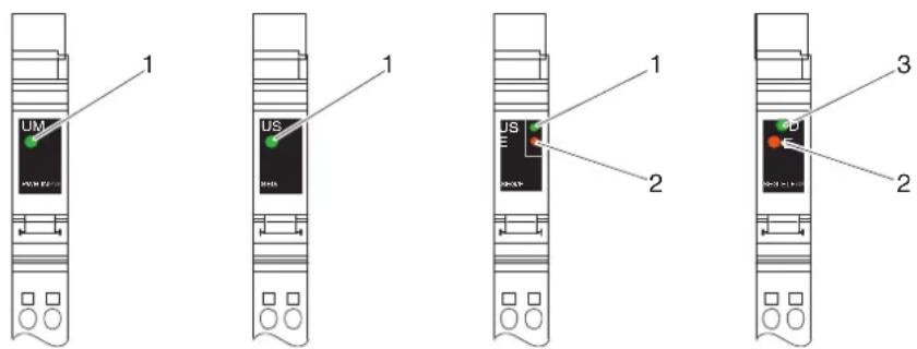
Figure 8-1 Possible indicators on power and segment terminals
Diagnostics The following states can be read on power and segment terminals:
| Power terminal | ||
| UM (1) | Green LED | Supply voltage in the main circuit (for meaning see page 88) |
| Segment terminal | ||
| US (1) | Green LED | Supply voltage in the segment circuit (for meaning see page 88) |
| Power terminal with fuse and diagnostics/segment terminal with electronic fuse | ||
| D (3) Green LED Diagnostics (for meaning see page 88) | ||
| Also on terminals with fuse | ||
| E (2) Red LED Fuse status | ||

On terminals with fuses, the green UM or US LED indicates that the main or segment voltage is present on the line side of the fuse, meaning that if the green LED is on, there is voltage on the line side of the fuse. If the red E LED is also on, the fuse has blown or is missing and no voltage is applied after the fuse.

If the red E LED is on and the green D LED is flashing at 2Hz on terminals with fuse and diagnostics, there is no voltage present after the fuse. Thus, a blown fuse is indicated by both diagnostic indicators (E and D).
8.1.4 Indicators on I/O terminals

In this section, I/O terminals are all terminals that acquire or output signals, i.e., all terminals excluding bus couplers, power, segment, and power-level terminals.

The LEDs of the I/O terminals are electrically located in the logic area. This may mean that the LED of an output is on but the output cannot be controlled due to an error between the logic area and the digital output. The LED does not monitor the output state. In the event of an error, the actual output state may differ from the state indicated by the LED.
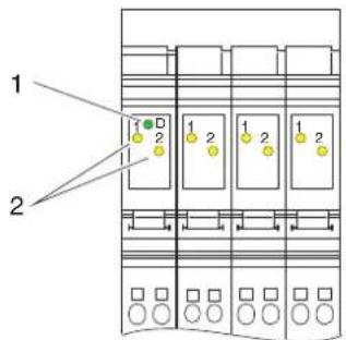
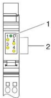
Figure 8-2 Indicators on I/O terminals
Diagnostics The following states can be read on I/O terminals:
| D(1) | Green LED Diagnostics (for meaning see page 88) |
Status The status of the input or output can be read from the relevant yellow LED:
| 1, 2,3, 4(2) | Yellow LED Status of the input/output | |
| ON: Corresponding input/output set | ||
| OFF: Corresponding input/output not set | ||
| For terminals with extended diagnostics | ||
| E1, E2,E3, E4 | Yellow LED The meaning depends on the terminal. It is described in the terminal-specific data sheet, e.g.,:Short circuit/overload of the initiator supplyShort circuit of an outputDiagnostic input error message | |
| ON: An error has occurred | ||
| OFF: | No error | |

Additional diagnostic or status indicators can be found on the terminals. They are described in the corresponding documentation.
Assignment between status LED and input/output
The figure shows the general principle of the assignment of a status LED to its input or output.
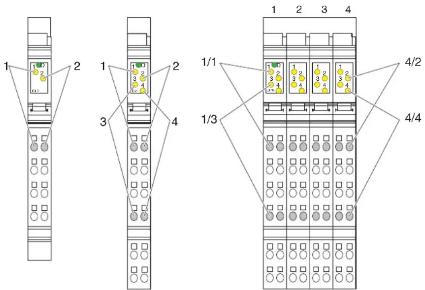
Figure 8-3 Assignment between status LED and input/output
Please refer to Section "Function identification and labeling" on page 53 for an explanation of the numbering.
With an 8-slot terminal, the LEDs of a slot belong to the terminal points of this slot. Every slot can be considered a 2-slot terminal.
For a 2-slot terminal with four inputs or outputs (middle example in Figure 8-3), the following LEDs belong to the following terminal points:
LED 1 Terminal point 1.1
LED 2 Terminal point 2.1
LED 3 Terminal point 1.4
LED 4 Terminal point 2.4
On the 8-slot terminal in Figure 8-3 and Figure 8-4, e.g., with 4/2, LED 2 on slot 4 is indicated. The LED belongs to input 14 at terminal point 4.2.1 (slot 4, terminal point 2.1).
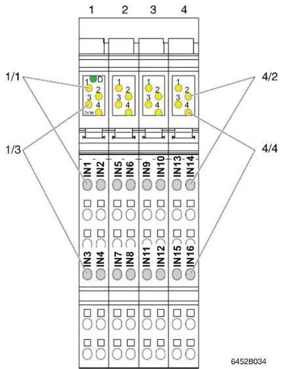
Figure 8-4 Assignment between status LED and input/output using the example of an IB IL 24 DI 16-PAC terminal

For every terminal, the assignment is specified in the terminal-specific data sheet.
8.1.5 Indicators on power-level terminals
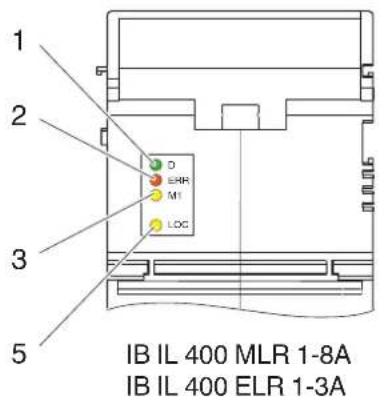
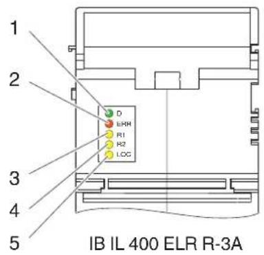
Figure 8-5 Indicators on power-level terminals
Diagnostics
The following states can be read on power-level terminals:
| D (1) Green LED Diagnostics (for meaning see page 88) | |
| ERR(2) | Red LED Group error message/motor protection |
| ON: Operating error (motor protection has been triggered, contactor cannot be controlled) | |
| OFF: No error | |
Status
The status of the motor and manual mode can be read from the corresponding yellow LED:
| M1(3) | Yellow LED Motor |
| ON: Motor switched on | |
| OFF: Motor not switched on | |
| R1(3) | Yellow LED Motor in direction of rotation 1 |
| ON: Motor in direction of rotation 1 switched on | |
| OFF: Motor in direction of rotation 1 not switched on | |
| R2(4) | Yellow LED Motor in direction of rotation 2 |
| ON: Motor in direction of rotation 2 switched on | |
| OFF: Motor in direction of rotation 2 not switched on | |
| LOC(5) | Yellow LED Manual mode (local) |
| ON: Manual mode active | |
| OFF: Bus mode active |
8.2 Indicators on Inline Block IO modules
An Inline Block IO module can be divided into the function areas bus system, supply, and I/O. Local diagnostic and/or status indicators are assigned to each function area.
8.2.1 Indicators in the bus system function area (BUS)

For the meaning of the diagnostic and status indicators in the bus system function area (BUS in Figure 8-6 on page 95) of the modules, please refer to the corresponding documentation.
8.2.2 Indicators in the supply function area (PWR)
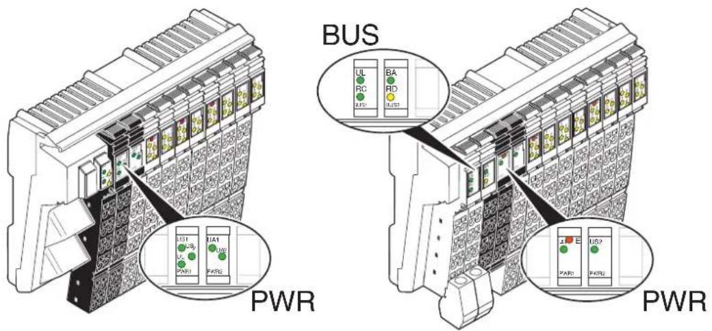
Figure 8-6 Possible indicators in the supply function area
Diagnostics
The following states can be read on the Inline Block IO modules:
| E Red LED | LED Sensor supply undervoltage | |
| ON: Sensor supply voltage too low | ||
| US Green | LED Sensor supply | |
| ON: Sensor supply present | ||
| OFF: Sensor supply not present | ||
| US1/2 | Green LED | Sensor supply 1/2 (for connector ... to connector ... sensors) |
| ON: Sensor supply 1/2 present | ||
| OFF: Sensor supply 1/2 not present | ||
| UA Green | LED Actuator supply | |
| ON: Actuator supply present | ||
| OFF: Actuator supply not present | ||
| UA1/2 | Green LED | Actuator supply 1/2 (for connector ... to connector ... actuators) |
| ON: Actuator supply 1/2 present | ||
| OFF: Actuator supply 1/2 not present | ||
| UL | Green LED 24 V communications power | |
| ON: 24 V communications power present | ||
| OFF: 24 V communications power not present | ||

The UL LED may be located in the supply (PWR) or bus (BUS) function area.
8.2.3 Indicators in the I/O function area (IN, OUT, IN/OUT)

The LEDs of the I/O function area are electrically located in the logic area.
This may mean that the LED of an output is on but the output cannot be controlled due to an error between the logic area and the digital output. The LED does not monitor the output state. In the event of an error, the actual output state may differ from the state indicated by the LED.
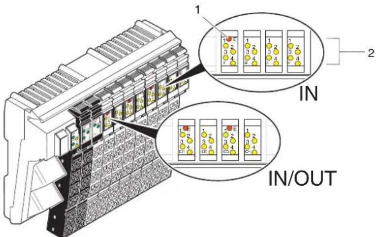
Figure 8-7 Indicators on I/O terminals
Status The status of the input or output can be read from the relevant yellow LED:
| 1, 2,3, 4(2) | Yellow LED Status of the input/output | |
| ON: Corresponding input/output set | ||
| OFF: Corresponding input/output not set | ||
| For terminals with extended diagnostics | ||
| E(1) | Red LED The meaning depends on the module. It is described in the module-specific data sheet, e.g.,:Short circuit/overload of a sensor supplyShort circuit at one or more outputs in the group | |
| ON: An error has occurred | ||
| OFF: | No error | |
Assignment between status LED and input/output
The figure shows the general principle of the assignment of a status LED to its input or output.
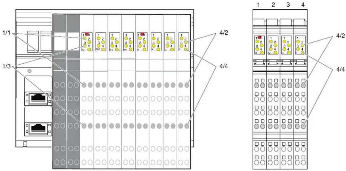
Figure 8-8 Assignment between status LED and input/output
Each slot in the LED area is labeled with the function, in Figure 8-8, e.g., IO1, IO2, ... I3, I4.
The principle of assignment between the LED and terminal point is the same for all slots. For each slot with four inputs or outputs, the following LEDs are assigned to the following terminal points:
LED 1 Terminal point 1.1
LED 2 Terminal point 2.1
LED 3 Terminal point 1.4
LED 4 Terminal point 2.4
On the module in Figure 8-8, e.g., with 4/2, LED 2 on slot I4 is indicated. According to the data sheet, the LED belongs to input 30 at terminal point I4.2.1 (slot I4, terminal point 2.1).
For every module, the assignment is specified in the module-specific data sheet.

9 Mounting/removing devices
9.1 Installation instructions
9.1.1 Unpacking
ESD regulations

NOTE: Electrostatic discharge
The devices contain components that can be damaged or destroyed by electrostatic discharge. When handling the devices, observe the necessary safety precautions against electrostatic discharge (ESD) according to EN 61340-5-1 and IEC 61340-5-1.
Unpacking
All devices are supplied in an ESD bag.
Only qualified personnel should pack, unpack, mount, and remove the device while observing the ESD regulations.
9.1.2 Replacing a device
When replacing a device, please observe the following.
- In the SELV area:

NOTE: Disregarding this warning may result in malfunction
Do not replace devices while the power is connected.
Inline Modular IO:
Before removing or mounting a terminal, disconnect power to the entire station.
Make sure the entire station is reassembled before switching the power back on.
– In the low voltage area (Inline Modular IO):

WARNING: Dangerous contact voltage
Do not replace devices while the power is connected.
Before removing or mounting a terminal, disconnect power to the entire station.
Make sure the entire station is reassembled before switching the power back on.
9.2 Basic information about mounting
Mounting location
Modules and terminals of the Inline product range have IP20 protection and are therefore designed for use in a closed control cabinet or control box (terminal box) with IP54 protection or higher.
DIN rail
All Inline Block IO modules and Inline Modular IO terminals are mounted on 35 mm standard DIN rails.
The modules are mounted perpendicular to the DIN rail. This ensures that they can be easily mounted and removed even when space is at a premium.
The distance between DIN rail fasteners must not exceed 200 mm. This distance is necessary for the stability of the rail when mounting and removing devices.

Figure 9-1 Fixing the DIN rail (in mm)
Mounting position
No specific mounting position is specified for the Inline Block IO modules or Inline Modular IO terminals. However, please refer to the ambient temperatures and any other special requirements (such as derating) specified in the data sheets.
Analog terminals are a special case. The accuracy data specified in the data sheets for these devices refers to the documented mounting position (usually horizontal DIN rail; Figure 9-2, detail A). The typical tolerance values for the relevant configurations are determined in this mounting position. Experience from previous testing indicates that the typical tolerances of analog terminals are slightly affected by the mounting position. This means that another mounting position is also possible in principle.
To ensure sufficient mechanical fixing for the Inline station or Inline Block IO module when mounting on a vertical DIN rail (Figure 9-2, detail B), we recommend the E/AL-NS 35 end clamp. This prevents the station or module from slipping down, particularly in the event of vibration.
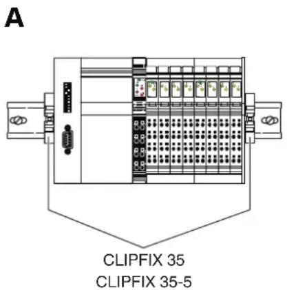
B
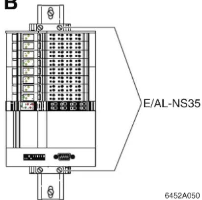
Figure 9-2 Mounting positions for an Inline station
9.3 Mounting distances
The space required for cable routing depends on the number of cables to be installed and must be left free on the left and/or right-hand side.
In order to minimize the parallel installation of signal and power supply lines, the cable duct on the left can be used for the signal and bus lines, for example, and the duct on the right for the power supply lines. This ensures that the parallel installation of these cable types is kept to a minimum and limits interference on the signal lines.
For the distances of the upper and lower cable ducts or the cable routing to the devices, please refer to the sections below.
9.3.1 Mounting distances for Inline Modular IO terminals
9.3.1.1 Mounting distances for terminals in the 24 V DC, 120 V AC, and 230 V AC areas (excluding terminals with fiber optic connections)
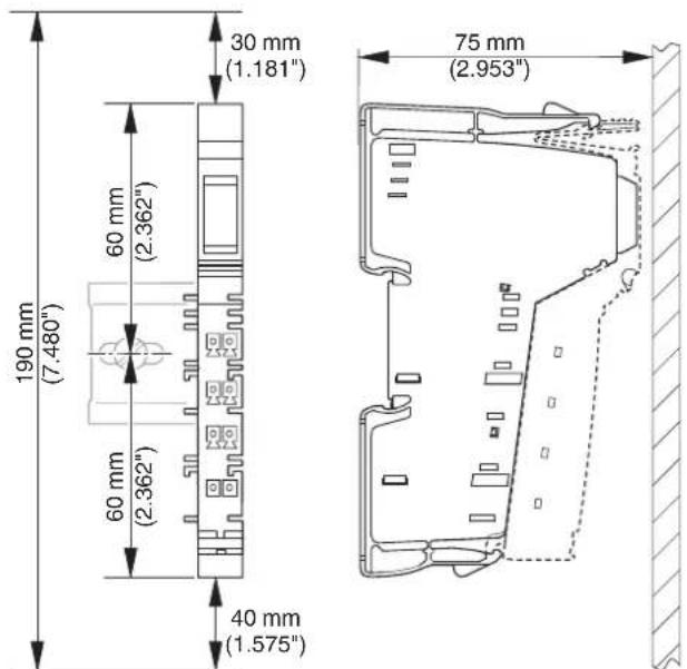
Figure 9-3 Mounting distances for terminals in the 24 V DC, 120 V AC, and 230 V AC areas

If the distances are smaller, the minimum bending radius of the cables, easy handling during installation, and a clear structure cannot be guaranteed.
9.3.1.2 Mounting distances for terminals with fiber optic connections
The bending radius and the space required for mounting terminals with fiber optic connections depends on the fiber optics used. Furthermore, the connector that is used affects the mounting distances.

Observe the instructions in the "IBS SYS FOC ASSEMBLY" fiber optic installation guidelines when determining the mounting distances.
According to the guidelines valid at the time of publication (Revision 03, 01/2007) the minimum bending radius for individual wires is 30 mm, and the minimum bending radius for a cable is either 50 mm or 65 mm depending on the cable. Using a fast connection connector with bend protection, for example, results in the following mounting distances:
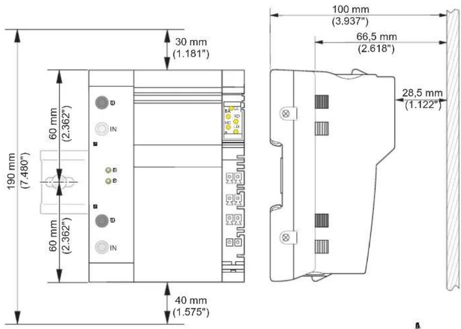
Figure 9-4 Example mounting distances for the IBS IL 24 BK-LK-PAC bus coupler when using individual wires (bending radius 30 mm)
9.3.1.3 Mounting distances for power-level terminals

NOTE: Overheating
The minimum vertical mounting distances shown in Figure 9-5 must be observed for power-level terminals to ensure sufficient ventilation of the power-level terminals.

Ensure additional space for installing the cables.
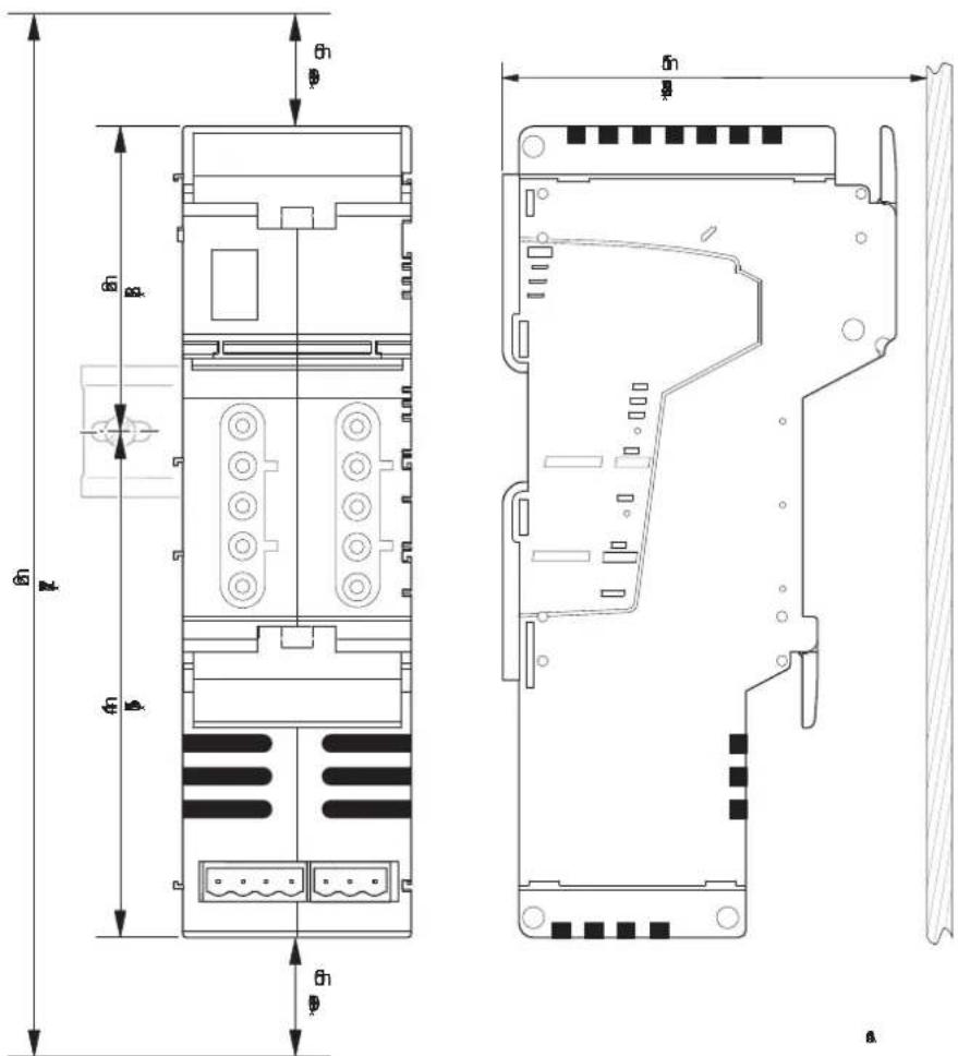
Figure 9-5 Mounting distances for power-level terminals
9.3.1.4 Mounting distances for mounting outside a terminal box
If the Inline stations are housed, e.g., in a control cabinet rather than a terminal box, the DIN rail distances depend on the previously specified mounting distances and the particular configuration of the individual Inline stations. The possible mounting distances are shown in Figure 9-6.
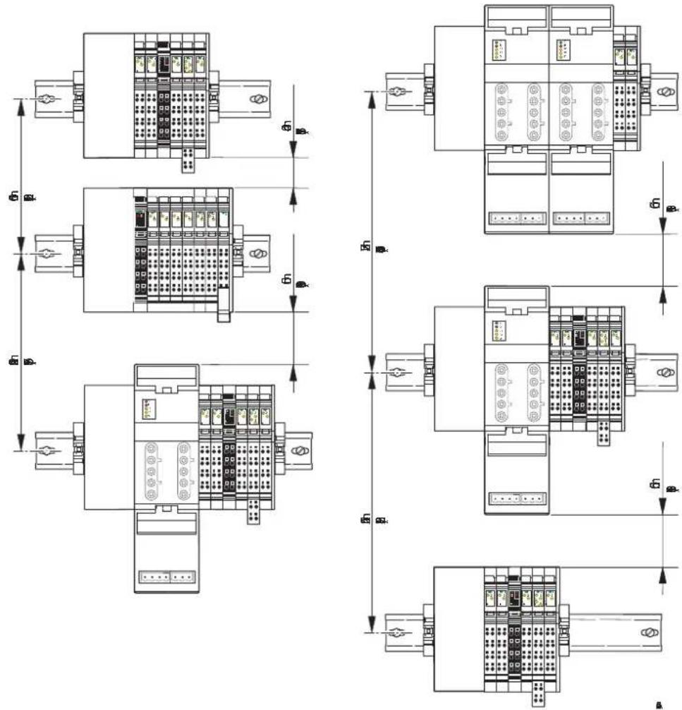
Figure 9-6 Mounting distances for mounting outside the terminal box for different station structures
9.3.2 Mounting distances for Inline Block IO modules
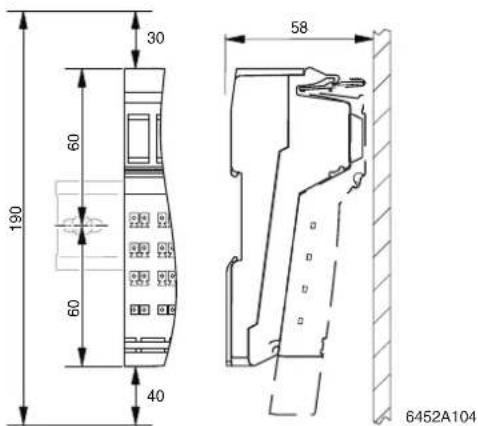
Figure 9-7 Mounting distances (in mm)

If the distances are smaller, the minimum bending radius of the cables, easy handling during installation, and a clear structure cannot be guaranteed.
9.4 Grounding concept

Within an Inline station, a distinction is made between functional earth ground (FE) and protective earth ground (PE).
For Inline Block IO modules, only functional earth grounding is used.
Protective earth grounding (PE)
Protective earth grounding protects people and machines against hazardous voltages. To avoid these dangers, correct installation, taking the local conditions into account, is vital.
Functional earth grounding (FE)
Functional earth grounding is used to improve noise immunity. All devices must be grounded so that any possible interference from data transmission paths is shielded and discharged to ground.
A 1.5 mm ^2 wire must be used for grounding spring-cage terminals.
9.4.1 Functional earth ground (FE)
Functional earth ground is a low-impedance current path between circuits and ground. It is not designed as a safety measure but rather, for example, for the improvement of noise immunity.

Functional earth ground (FE) is only used to discharge interference. It does not provide shock protection for people.
Functional earth ground is used within the 24 V DC area (SELV).
To ensure reliable functional earth grounding of the station, various points must be observed.
Inline Modular IO
For Inline Modular IO terminals, functional earth ground is led from the grounded bus coupler through the 24 V DC area of the station using the FE potential jumper.
1 The bus coupler, power terminals, and segment terminals have an FE spring (metal clip) on the bottom of the electronics base. This spring establishes an electrical connection to the DIN rail. Use grounding terminals to connect the DIN rail to protective earth ground. The terminals are grounded when they are snapped onto the DIN rail.
2 Phoenix Contact also recommends grounding the Inline Modular IO bus coupler via the FE terminal point of the corresponding connector to ensure reliable functional earth grounding even if the DIN rail is dirty or the metal clip is damaged (see terminal-specific data sheet).
3 A 120 V AC or 230 V AC voltage area interrupts the FE potential jumper. Therefore, a 24 V DC power terminal, which is installed directly after such an area, must also be grounded via the FE terminal point (see terminal-specific data sheet).
Any additional Inline low-level signal terminals are automatically grounded via the FE potential jumper when they are properly installed.
The FE potential jumper is looped through the power-level terminals.
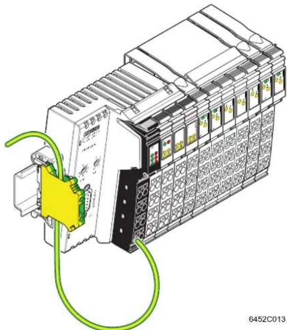
natural_image
Illustration of an industrial control unit with wiring and connector (no text or symbols)Figure 9-8 Additional functional earth grounding of a bus coupler (Example: IL PB BK DI8 DO4-PAC)

Figure 9-8 shows the additional grounding for a bus coupler using the example of the IL PB BK DI8 DO4-PAC bus coupler. Connect the additional grounding to your device according to the terminal-specific documentation.
Inline Block IO
1 The modules have an FE spring (metal clip) on the bottom of the electronics base. This spring establishes an electrical connection to the DIN rail. Use grounding terminals to connect the DIN rail to protective earth ground. The modules are grounded when they are snapped onto the DIN rail.
2 Phoenix Contact also recommends grounding the Inline Block IO module via the FE terminal point of the corresponding connector to ensure reliable functional earth grounding even if the DIN rail is dirty or the metal clip is damaged (see terminal-specific data sheet).
9.4.2 Protective earth ground (PE) (Inline Modular IO)
Protective earth ground is a low-impedance current path that minimizes the risk to the operator in the event of an error (including a high voltage and/or current error between an electrical circuit and ground).
In Inline terminals, protective earth ground is used outside the SELV.

WARNING: Disregarding this warning may result in the loss of electrical safety
Every power terminal of the 120 V AC or 230 V AC area must be connected to the DIN rail with low impedance, otherwise no protection is provided.
The PE (protective earth ground) potential jumper is led from the power terminal of the 120 V AC or 230 V AC area through this entire area to the next power terminal.
Power-level terminals are connected to PE using the power connector and voltage continuation between power-level terminals is ensured using the power bridge.
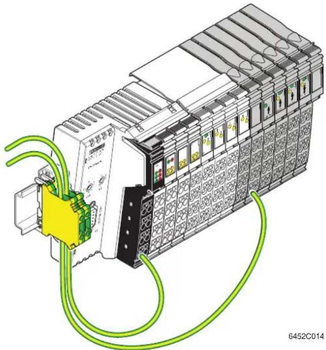
natural_image
Illustration of an industrial control unit with wiring and connectors (no text or symbols)Figure 9-9 Additional grounding of a bus coupler and protective earth ground connection (Example: IL PB BK DI8 DO4-PAC)

Figure 9-9 shows the additional grounding and protective earth ground connection using the example of the IL PB BK DI8 DO4-PAC bus coupler. Connect the additional grounding and protective earth ground to your devices according to the terminal-specific documentation.
9.5 Shielding concept
Shielding is used to reduce the effects of interference on the system.
9.5.1 Inline shielding concept
In the Inline system, shielded cables are used with the following terminals:
- Remote bus cables
-
Connecting cables
-
At terminals for analog signals (analog input, analog output, temperature recording)
- At terminals for open and closed-loop control
- At communication terminals
- At detection terminals
- At programmable terminals
Observe the following points when installing shielding:
- Secure the shielding so that as much of the braided shield as possible is held underneath the clamp of the shield connection.
- Make sure there is good contact between the connector and base.
- Do not damage or squeeze the wires.
- When connecting the shielding, observe the specifications for the connector wiring.
9.5.2 Shielding when connecting analog sensors and actuators
- Always connect analog sensors and actuators with shielded, twisted pair cables.
- Connect the shielding via the Inline connector with shield connection (see Section "Connecting shielded cables using an Inline shield connector" on page 124).
When connecting the cables, observe the instructions in the terminal-specific data sheets.
- As a rule, shielding must only be connected directly to the PE potential on one side. This is to prevent any occurrence of voltage equalization currents via the shielding.
- If necessary, integrate the shielding concept for analog I/O cables into the system concept, for example, it is useful to use a central FE shield connection at the control cabinet entry.

Example: Integration of analog shielding in a concept with central equipotential bonding at the control cabinet entry
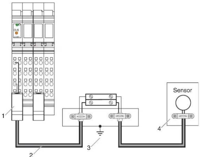
Figure 9-10 Integration of analog shielding in a concept with central equipotential bonding at the control cabinet entry
1 Lead the analog cable into the Inline connector making sure to maintain the cable insulation.
2 Use shielded twisted pair cables.
3 Connect the strain relief directly to PE potential.
Connect the shield for the entire analog transmission path to PE potential at just one point. In the example above, this point is the jumpering level (C).
4 Lead the sensor cable into the sensor making sure to maintain the cable insulation.

NOTE: Possible malfunctions
When integrating the shielding of analog I/O cables in an equipotential bonding concept, make sure that direct connection to the PE potential is only made at one point (e.g., at the central grounding point of the jumpering level).
9.6 Mounting/removal
9.6.1 Inline Modular IO: Mounting/removal
| Mounting side by side (Inline Modular IO) | An Inline station is set up by mounting the individual components side by side. No tools are required. Mounting the components side by side automatically establishes the potential and bus signal connections between the individual station components.After a station has been set up, individual terminals can be exchanged by pulling them out or plugging them in. Tools are not required. |
| End clamps (Inline Modular IO) | Mount end clamps on both sides of the Inline station. The end clamps ensure that the Inline station is correctly mounted. End clamps secure the Inline station on both sides and keep it from moving from side to side on the DIN rail. For the recommended end clamps, please refer to Section “Ordering data” on page 153.When mounting on a horizontal DIN rail, the end clamps can be snapped onto the DIN rail at any point during station assembly.When mounting on a vertical DIN rail, secure the end clamp on the left at the start of station assembly, so as to prevent the station from slipping down. |
| End plate (Inline Modular IO) | The end plate terminates an Inline station. It has no electrical function. It protects the station against ESD pulses and the user against dangerous contact voltages. The end plate is supplied with the bus coupler and does not have to be ordered separately. |
| Order of the Inline terminals | When mounting, observe the correct order of the Inline terminals (see Section “Order of the Inline Modular IO terminals” on page 120). |
9.6.1.1 Mounting/removing/replacing terminals in the 24 V DC and 120 V AC/230 V AC areas
Mounting
When mounting a terminal in these areas, proceed as shown in Figure 9-11 on page 113:
- Disconnect the power to the station.
- First snap on the electronics base, which is required for mounting the station, perpendicular to the DIN rail (detail A).

When doing this ensure that all featherkeys and keyways on adjacent terminals are securely interlocked (detail B).
The keyway/featherkey connection links adjacent terminals together and ensures that data and potential routing is created safely.
- First, insert the data jumper for the bus interface in the guideways by snapping it onto the previous terminal (detail B1).

NOTE: Malfunction in the event of no contacting
Press gently against the adjacent terminal on the left to make sure that the featherkey has snapped into its keyway on the bus interface.
- Then insert the other potential jumpers into their guideways and snap the featherkeys into the corresponding keyways (detail B2).
- Detail C1 shows a common error. Here, the bus interface has not contacted properly. The featherkey is not in the keyway. The bus is not running or is running with errors ("loose contact").
- Detail C2 shows secure contacting of the data jumpers and the interlocking keyway/featherkey connection.
- Once all the bases have been snapped on, plug the connectors into the appropriate bases.
First, place the front connector shaft latching in the front snap-on mechanism (detail D1).
Then press the top of the connector towards the base until it snaps into the back snap-on mechanism (detail D2).

The keyways of an electronics base do not continue on a connector. When snapping on an electronics base, there must be no connector on the left-hand side of the base. If a connector is present, it will have to be removed.
A
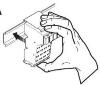
natural_image
Hand holding a mechanical component with a bracket and internal structure (no text or symbols visible)B
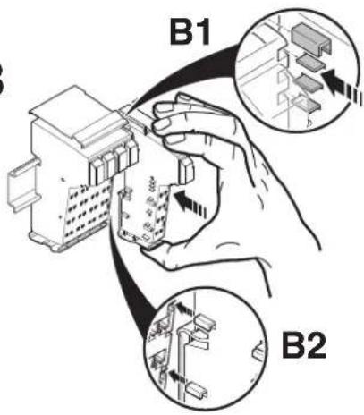
C
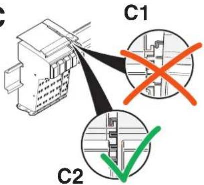
D
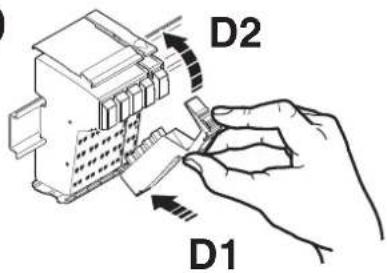
Figure 9-11 Mounting a terminal
Removal
When removing a terminal, proceed as shown in Figure 9-12 on page 114:
- Disconnect the power to the station.
- If there is a labeling field, which covers several connectors, it may have to be removed (detail A1).

If a terminal has several connectors, all connectors of the terminal must be removed. The following describes how a 2-slot terminal is removed.
- Lift the connector of the terminal to be removed by pressing on the back connector shaft latching (detail A2).

When using extended double signal connectors (long connectors), please ensure that you do not bend them back too far, as you may break the front snap-on mechanism.
- Remove the connector (detail B).
- Remove the adjacent connectors of the neighboring terminals (detail C). This prevents the potential routing knife contacts and the keyway/featherkey connections from being damaged. You also have more space available for accessing the terminal.
- Press the snap-on mechanism (detail D1), and remove the electronics base from the DIN rail by pulling the base straight back (detail D2). If you have not removed the connector of the adjacent terminal on the left, remove it now in order to protect the potential routing knife contacts and the featherkeys of the keyway/featherkey connection.
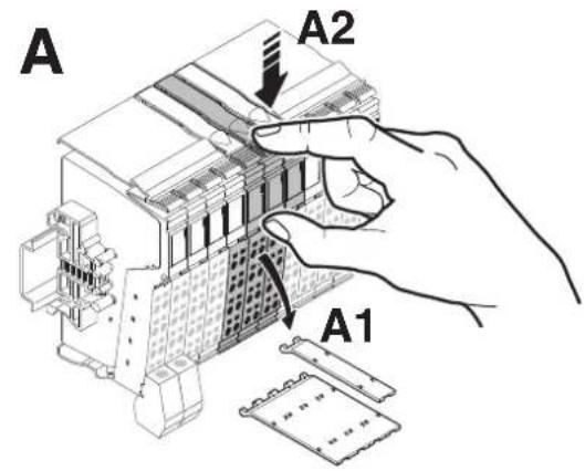
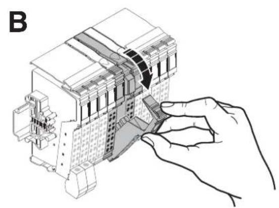
natural_image
Technical line drawing of a mechanical assembly with a hand adjusting a component (no text or symbols present)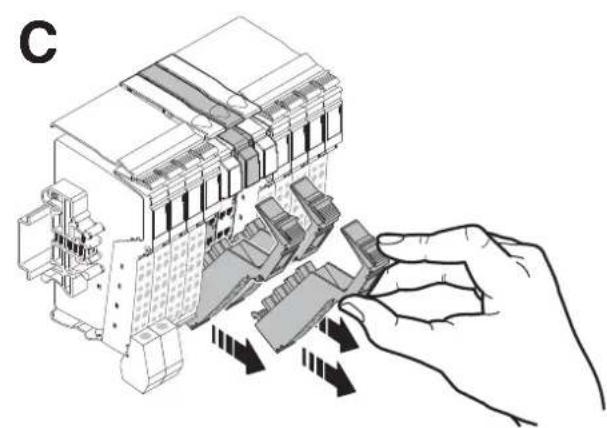
natural_image
Diagram of a hand inserting or adjusting a device into a multi-chambered electrical enclosure (no text or symbols present)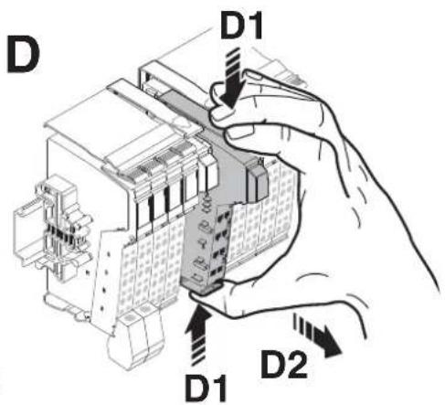
Figure 9-12 Removing a terminal
Replacing a terminal
If you want to replace a terminal within the Inline station, follow the removal procedure described above. Do not snap the connector of the adjacent terminal on the left back on yet. Insert the base of the new terminal.

When doing this ensure that all featherkeys and keyways on adjacent terminals are securely interlocked.

Then reconnect all the connectors.
The top connector latching must click into place.
9.6.1.2 Replacing a fuse
The 24 V DC power and segment terminals are also available in versions with a fuse. If a fuse is not present or faulty, you must insert or replace it.

WARNING: Observe the following notes when replacing a fuse for the protection of your health and your system.
- Use the screwdriver carefully to avoid injury to yourself or other persons.
- Lift the fuse out at the metal contact. Do not lift the fuse out at the glass part as this may break it.
- Carefully lift the fuse out at one side and remove it by hand. Make sure the fuse does not fall into your system.
When replacing a fuse, proceed as shown in Figure 9-13 on page 116:
- Lift the fuse lever (detail A).
- Insert the screwdriver behind a metal contact of the fuse (detail B).
- Carefully lift out the metal contact of the fuse (detail C).
- Remove the fuse by hand (detail D).
- Insert a new fuse (detail E).
- Push the fuse lever down again until it clicks into place (detail F).
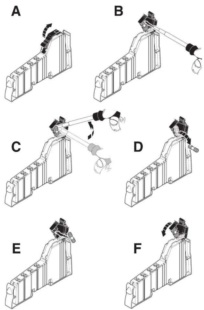
Figure 9-13 Replacing a fuse
9.6.1.3 Mounting/removing power-level terminals
Observe the following safety notes and warning instructions when working on power-level terminals.

WARNING: Dangerous contact voltage
Only work on power-level terminals and connectors when the power is disconnected.

Observe the safety notes and warning instructions provided in the terminal-specific data sheets.
Mounting
When mounting a power-level terminal, proceed as shown in Figure 9-14:
- Snap on the power housing, which is required for mounting the station, perpendicular to the DIN rail (detail A).

When doing this ensure that all featherkeys and keyways on adjacent terminals are securely interlocked.
The keyway/featherkey connection links adjacent terminals together and ensures that potential routing is created safely.

The keyways of an electronics base do not continue on the connector of terminals for the 24 V DC area. When snapping on a power housing, there must be no 24 V connector on the left-hand side of the housing. If a connector is present, it will have to be removed.
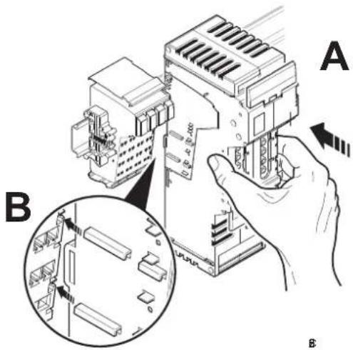
Figure 9-14 Mounting a power-level terminal
- Next, attach the required connectors to the housing. The available connections are described in Section "Connections on a power-level terminal (Inline Modular IO)" on page 139.
Removal
When removing a terminal, proceed as shown in Figure 9-15:
- If adjacent terminals belong to the 24 V DC or 120 V AC/230 V AC area: Remove the adjacent connectors of the neighboring terminals (Figure 9-12 on page 114). This prevents the potential routing knife contacts and the keyway/featherkey connection from being damaged.
- Lift the release flaps towards the center of the power-level terminal (Figure 9-15, detail A).
- Remove the power-level terminal by uniformly pulling the release flaps straight back from the DIN rail (detail B). If you have not removed the connector of the adjacent terminal on the left, remove it now in order to protect the potential routing featherkeys and the keyway/featherkey connection.
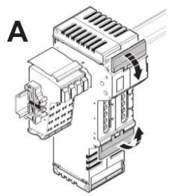
natural_image
Technical line drawing of an industrial electrical enclosure with cooling fans and heat exchangers (no text or symbols)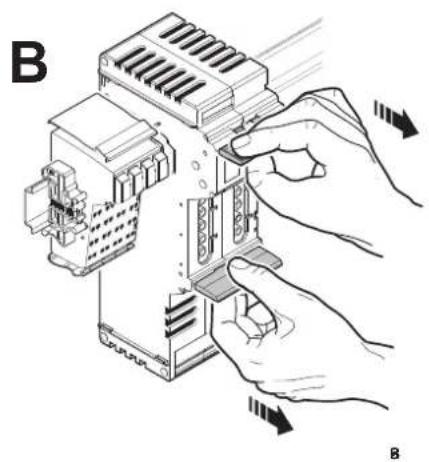
natural_image
Illustration of hands installing or adjusting a device component with arrows indicating motion (no text or symbols present)Figure 9-15 Removing a power-level terminal
9.6.2 Inline Block IO: Mounting/removal
Mounting
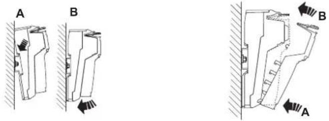
Figure 9-16 Snapping on the base Figure 9-17 Snapping on a connector
- Place the base onto the DIN rail from above (Figure 9-16, A) and press down firmly (B).
- Plug the connectors into the base (Figure 9-17). First, insert the front connector shaft latching (A). Then press the top of the connector towards the base until it snaps into place (B).
Removal
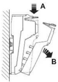
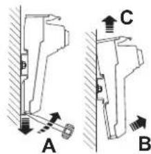
Figure 9-18 Removing a connector Figure 9-19 Removing the base
- Disconnect the power to the module.
• If there is a labeling field, which covers several connectors, it may have to be removed.

Before removing the base, disconnect all the necessary connectors, so as to provide access to the base latch.
When using extended double signal connectors (long connectors), please ensure that you do not bend them back too far, as you may break the front snap-on mechanism.
- Lift the connector that is to be removed by pressing on the back connector shaft latching (Figure 9-18, A).
- Remove the connector (B).
- Insert a tool in the base latch and pull gently upwards (Figure 9-19, A). Pull the module out from the DIN rail (B, C).
9.6.3 Order of the Inline Modular IO terminals
9.6.3.1 General order
The order of the terminals within an Inline station should depend on the current consumption of the I/O from the potential jumpers U_M and U_S .
As the voltage at every power terminal is reinjected into the potential jumpers U_M and U_S , the section (main circuit) between a bus coupler and a power terminal or between a power terminal and another power terminal must always be considered when calculating the current. If power terminals are not used, the entire station is a main circuit.
Within a main circuit, install the terminals according to their current consumption. Install the terminals with the highest current consumption first. This has the advantage that the high supply current does not flow through the entire main circuit and thus does not flow through all the terminals.
The following order is recommended.
Table 9-1 Order of the Inline terminals within a main circuit
| Function Abbreviation | in order designation | Function identi-fication | Note | |
| 1 | Digital output DO, SDO | Pink, red, | dark red | In descending order of current consumption |
| 2 | Digital input DI, SDI Light | blue, blue, | dark blue | In descending order of current consumption |
| 3 | Relay DOR, SDOR Dark | red | ||
| 4 | Power ELR, MLR, | EC AR, DC AR | Dark red See also | 9.6.3.4 |
| 5 | Special functions | Orange | In descending order of current consumption | |
| - Open and closed-loop control | PWM, CNT, SSI, INC, TEMPCON | |||
| - Communication | RS, ASI MA, DALI | |||
| - Detection | INC-IN, SSI-IN, IMPULSE-IN | |||
| - Safety | SAFE | Please observe any special requirements (subsequent safety-related segment circuit or subsequent power-level terminals). | ||
| 6 | Analog output | AO | Yellow | In descending order of current consumption; see also 9.6.3.3 |
| 7 | Analog input | AI, SGI, TEMP | Green | In descending order of current consumption; see also 9.6.3.3 |
| IB IL TEMP 2/UTH-PAC | As the last terminal |
Please also observe the following notes:
- In the event of any further restrictions regarding the position of a terminal, please refer to the terminal-specific data sheet.
- For the current consumption of the terminals, please refer to the relevant terminal-specific data sheet.
9.6.3.2 Remote bus branch in an Inline station
If you want to integrate a remote bus branch into an Inline station, please note that the terminal with remote bus branch must be placed directly after a bus terminal, an Inline Controller or another terminal with remote bus branch.

Please refer to the corresponding data sheets to see if any other special requirements should be observed.
9.6.3.3 Positioning terminals for analog signals
High current flowing through potential jumpers U_M and U_S leads to a temperature rise in the potential jumpers and inside the terminal. This reduces the measuring accuracy and shortens the service life of the terminal.
To keep the current flowing through the potential jumpers of the analog terminals as low as possible, always place the analog terminals after all the other terminals at the end of the main circuit.

Within the analog terminals, position the IB IL TEMP 2/UTH-PAC terminal after all the other terminals to keep the current flowing through all the potential jumpers for this terminal as low as possible.
9.6.3.4 Positioning power-level terminals
In a 24 V DC area, position the power-level terminals anywhere in the main circuit, but before the analog terminals.
In a 24 V DC area, power-level terminals can be positioned anywhere in the main circuit before terminals with a special function and analog terminals. Due to noise emissions, power-level terminals with mechanical load relay (MLR) should be positioned away from analog terminals, i.e., they must not be placed adjacent to them.

Please note that only adjacent power-level terminals can be connected for potential jumpering using power bridges.
9.6.3.5 Example of the structure of a main circuit
Table 9-2 Example: Structure of a main circuit
| TerminalTypeReason for position | ||
| 1 IB IL 24 DO 16-PAC | Digital output terminal | DO, current higher than for 2;please observe note below table |
| 2 IB IL 24 DO 2-PAC Digital output terminal DO | ||
| 3 IB IL 24 DI 16-PAC | Digital input terminal | DI, current higher than for 4 |
| 4 IB IL 24 DI 2-PAC Digital input terminal DI | ||
| 5 IB IL 400 MLR 1-8A | Power-level terminal | Any, before analog |
| 6 IB IL CNT-PAC Function terminal | ||
| 7 IB IL AO 2/SF-PAC Analog output terminal AO | ||
| 8 IB IL TEMP 2/UTH-PAC | Analog input terminal | AI, after all others |

NOTE:
In the event of high simultaneity of digital outputs and maximum current load, insert a power terminal after the IB IL 24 DO 16-PAC terminal.
If the maximum load of the outputs is 0.2 A, an additional power terminal is not required. This configuration is in Figure 9-20.
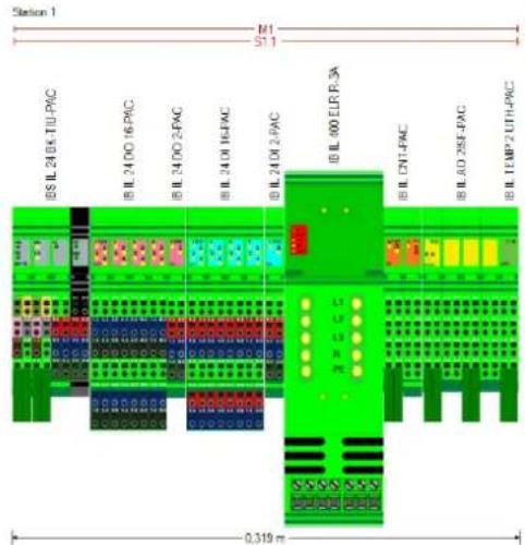
Figure 9-20 Suggested solution
10 Connecting cables
10.1 Connecting cables using Inline connectors
Excluding a few exceptions, the cables for the I/O and supply voltages are connected via Inline connectors using the spring-cage method. This means that signals up to 250 V AC/DC and 8 A can be connected with a conductor cross-section of 0.08 mm^2 to 1.5 mm^2 .

Please observe the permissible lengths for sensor/actuator cables (see Section "Cable connection method/cross-section" on page 151 or terminal-specific data sheet).
Both shielded and unshielded cables are used with Inline Modular IO terminals or Inline Block IO modules.
10.1.1 Connecting unshielded cables
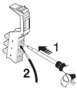
Figure 10-1 Connecting unshielded cables
Wire the connectors according to your application.

For the connector pin assignment, please refer to the corresponding terminal-specific data sheet.
When wiring, proceed as follows:
- Strip 8 mm off the cable.

Inline wiring is normally done without ferrules. However, it is possible to use ferrules. If using ferrules, make sure they are properly crimped.
- Push a screwdriver into the slot of the appropriate terminal point (Figure 10-1, detail 1), so that you can insert the wire into the spring opening.
Phoenix Contact recommends using a SZF 1 - 0,6X3,5 screwdriver (Order No. 1204517). - Insert the wire (Figure 10-1, detail 2). Remove the screwdriver from the opening. This clamps the wire.
Following installation, the wires and the terminal points should be labeled (see also Section "Function identification and labeling" on page 53).
10.1.2 Connecting shielded cables using an Inline shield connector
Shielded cables can be connected via IB IL SCN-6 SHIELD and
IB IL SCN 6-SHIELD-TWIN shield connectors. The IB IL SCN-6 SHIELD shield connector is designed to connect one shielded cable. Two shielded cables can be easily connected via the IB IL SCN 6-SHIELD-TWIN shield connector. In principle, cables are connected via the shield connector in the same way as shown in Figure 10-2 on page 125 and Figure 10-3 on page 126.
Figure 10-2 shows the connection of a shielded cable using a remote bus cable as an example. In this example, the cables are twisted pair cables.
Figure 10-3 shows the connection of two shielded cables, using the wiring of the IB IL AI 2/SF-PAC terminal as an example. As two channels can be used here, the IB IL SCN 6-SHIELD-TWIN shield connector is used.
When connecting the cables proceed as shown in Figure 10-2 and Figure 10-3:
Stripping cables
- Strip the outer cable sheath to the desired length (a) (detail A).
The desired length (a) depends on the connection position of the wires and whether the wires should have a large or small amount of space between the connection point and the shield connection. - Shorten the braided shield to 15 mm (detail A).
- Fold the braided shield back over the outer sheath (detail B).
- Remove the protective foil.
- Strip 8 mm off the wires (detail B).

Inline wiring is normally done without ferrules. However, it is possible to use ferrules. If using ferrules, make sure they are properly crimped.

When using twisted pair cables, keep the wire twisted until just before the terminal point.
Wiring the connectors
- Push a screwdriver into the actuation shaft of the appropriate terminal point (Figure 10-1 on page 123, detail 1), so that you can insert the wire into the spring opening.
Phoenix Contact recommends using a SZF 1 - 0,6X3,5 screwdriver (Order No. 1204517).
- Insert the wire (Figure 10-1 on page 123, detail 2). Remove the screwdriver from the opening. This clamps the wire.

For the connector pin assignment, please refer to the corresponding terminal-specific data sheet.
Connecting the shield
Figure 10-2 shows the shield connection for the IB IL SCN 6-SHIELD connector. The procedure for the IB IL SCN 6-SHIELD-TWIN connector (shown in Figure 10-3) is the same.
- Open the shield connection (detail C).
- Check the position of the shield connection clamp in the shield connection (see also "Shield connection clamp" on page 127).
- Place the cable with the folded braided shield in the shield connection (detail D).
- Close the shield connection (detail E).
- Tighten the screws on the shield connection with a screwdriver (detail F).

To ensure that the shield connection clamp remains in place when the shield connection is closed, first secure the shield clamp with screws and then close the shield connection.
A B C
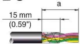
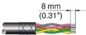
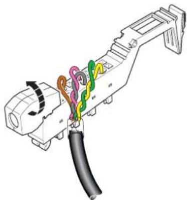
natural_image
Diagram of a connector with colored wires and cable, no text or symbols present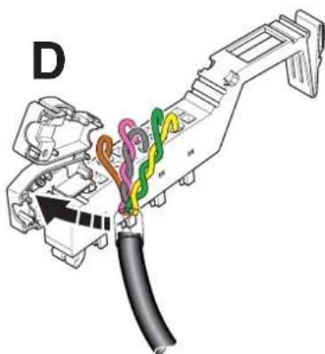
natural_image
Diagram of a connector assembly with colored wires and cable (no text or labels)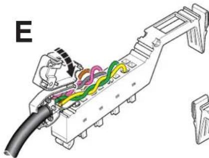
natural_image
Technical diagram of a mechanical assembly with colored wires and components (no text or labels)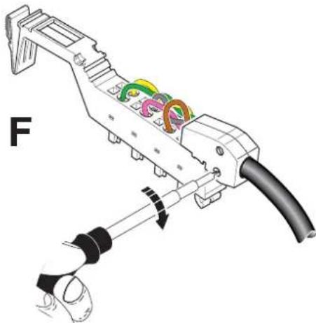
natural_image
Mechanical assembly diagram showing a tool with colored components and a labeled section 'F' (no text or symbols on the diagram itself)Figure 10-2 Connecting a shielded cable via the IB IL SCN-6 SHIELD shield connector
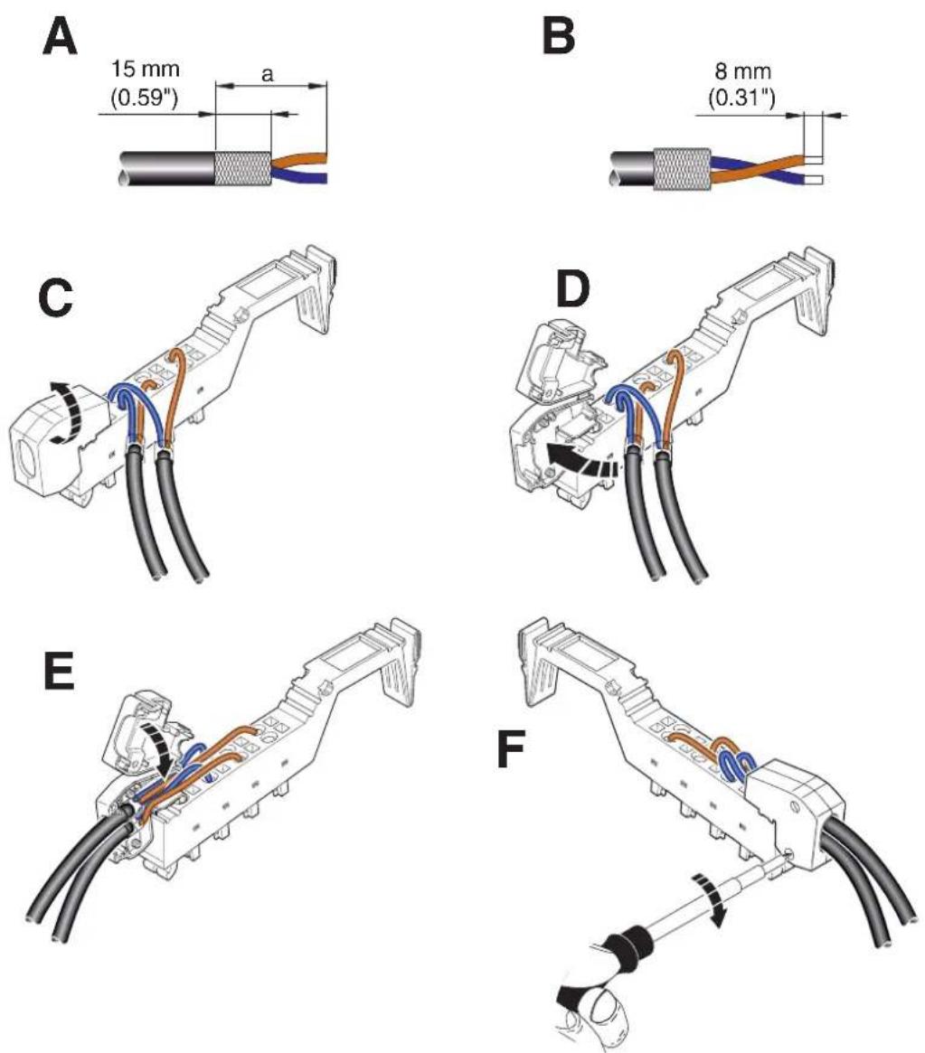
Figure 10-3 Connecting two shielded cables via the IB IL SCN 6-SHIELD-TWIN shield connector
Shield connection clamp
The shield connection clamp (a in Figure 10-4, detail B) in the shield connection can be used in various ways depending on the cable cross-section. For thicker cables (e.g., bus cable), the dip in the clamp must be turned away from the cable (Figure 10-4, detail B). For thinner cables, the dip in the clamp must be turned towards the cable (Figure 10-4, detail F).
If you need to change the position of the shield connection clamp, proceed as shown in Figure 10-4:
- Open the shield connection housing (detail A).
- The shield connection is delivered with the clamp positioned for connecting thicker cables (detail B).
- Remove the clamp (detail C), turn it to suit the cross-section of the cable (detail D), then reinsert the clamp (detail E).
• Detail F shows the position of the clamp for a thin cable.
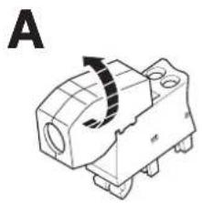
natural_image
Technical line drawing of a mechanical component with a curved arrow indicating rotation (no text or symbols)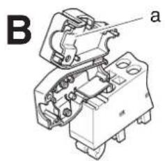
natural_image
Technical line drawing of an electrical component with labeled parts (a), no readable text or symbols present.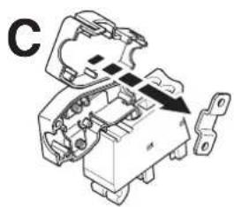
natural_image
Mechanical assembly diagram showing a component with internal parts and an arrow indicating direction (no text or symbols)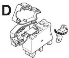
natural_image
Technical line drawing of an electrical component with no visible text or symbols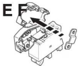
natural_image
Mechanical component diagram showing internal parts and a directional arrow (no text or symbols)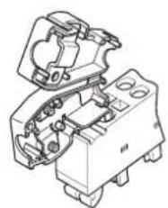
natural_image
Technical line drawing of a mechanical assembly with no visible text or symbolsFigure 10-4 Shield connection clamp alignment
10.1.3 Connecting shielded cables using an Inline connector
With analog, function, or communication terminals without Inline shield plug, shielding can be connected by separate accessories. Connect the shielding with the shielding accessories given in the ordering data.
Please refer to the "Ordering data for accessories: shield connection" on page 153 for the recommended accessories. You will also find the relevant information in the terminal-specific data sheet.
10.2 Connecting the power supplies
Inline Modular IO
To operate an Inline station you must provide the supply voltage for the bus coupler, the logic of the terminals, and the sensors and actuators.
Connect the power supplies using unshielded cables as described in Section "Connecting unshielded cables" on page 123.

For the connector pin assignment of the supply voltage connections, please refer to the terminal-specific data sheets for bus couplers, power terminals, and segment terminals.
Inline Block IO
When using Inline Block IO modules, the supply voltage for the module and the sensors and actuators must be provided. Depending on the module, connection can be via Inline connector or COMBICON connector.
The power supplies are connected using unshielded cables. For connection via Inline connector, see Section “Connecting unshielded cables” on page 123.

For the connector pin assignments for connecting supply voltages, please refer to the relevant module-specific data sheet.
10.2.1 Inline Modular IO: Supply options
Bus coupler supply

For detailed information, please refer to the documentation for your bus coupler.
Power terminal supply
Depending on the type of power terminal, the following supply voltages can be supplied or provided:
- U_M and U_S (I/O supply voltage)
- U_24V (generation of U_L and U_ANA ), U_M , and U_S (communications power and I/O supply voltage)

Please also refer to the information provided in Section “Power, segment, and accessory terminals” on page 29.
Providing the segment voltage at segment terminals
At segment terminals, the segment voltage U_S is provided from the main circuit U_M .

Please also refer to the information provided in Section "Power, segment, and accessory terminals" on page 29.
Notes on supply voltages
The bus coupler supplies the module electronics of the connected terminals with communications power ( U_L ), which is generated, for example, from the bus coupler supply voltage ( U_BK ). If the supply voltage U_BK is disconnected, the bus stops.
The supply voltage to the sensors and actuators ( U_M/U_S ) should be installed and protected independently of the bus coupler supply ( U_BK ). In this way the bus continues to run even if some I/O devices are switched off.
10.2.2 Power supply requirements

WARNING: Dangerous contact voltage
Only use power supply units that ensure safe isolation between the primary and secondary circuits according to EN 50178.

For additional power supply requirements, please refer to the documentation for your bus coupler and the power terminals.
Inline Modular IO: Supply voltage requirements that differ from the system specifications
The specifications for Inline system supply voltages are described in “Technical data for Inline Modular IO” on page 147. However, some terminals have specific requirements. Therefore, always refer to the corresponding data sheet.
This section provides information about the various possible requirements within an Inline system.
Table 10-1 Supply voltage requirements of various products (example)
| Inline (system requirements) | IB IL 400 MLR 1-8A | |
| Nominal voltage 24 V DC 24 V DC | ||
| Ripple ±5% ±5% | ||
| Permissible voltage range (including ripple) | 19.2 V DC to 30.0 V DC | 19.2 V DC to 28.8 V DC |
| Documented in “Technical data for Inline Modular IO” on page 147 | Data sheet | |

If you are using Inline in a system with other product ranges, also observe the technical data for these product ranges. Please refer to the corresponding documentation for this technical data.
Two options are available when using terminals, which have special requirements regarding the power supply:
1 Observe the specific parameters for the power supply in the entire system.
2 Observe the specific parameters in the main circuit where the terminals are located.
10.3 Recommendation for supplying the supply voltage and resetting the voltage with regard to Inline Modular
10.3.1 Supply at the bus head
In the Inline terminals, electrical isolation is implemented between the logic and I/O devices. To prevent decreasing the electrical isolation, the voltages for supplying the logic and for supplying the I/O devices must be provided separately using two separate power supply units.
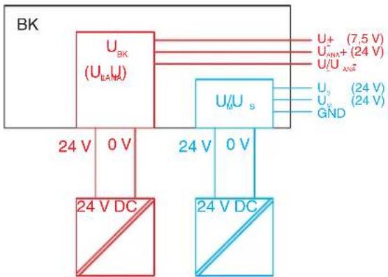
flowchart
graph TD
    A["24 V DC"] --> B["U_BK (U_BAN)"]
    B --> C["U_0 U_s"]
    C --> D["U_1 U_2 (7.5 V)"]
    C --> E["U_2 U_3 (24 V)"]
    C --> F["U_3 U_4 (24 V)"]
    C --> G["U_4 U_5 (24 V)"]
    B --> H["24 V DC"]
    C --> I["24 V U_s"]
    style A fill:#f9f,stroke:#333
    style B fill:#ccf,stroke:#333
    style C fill:#cfc,stroke:#333
    style D fill:#fcc,stroke:#333
    style E fill:#cff,stroke:#333
    style F fill:#ffc,stroke:#333
    style G fill:#fcf,stroke:#333
Figure 10-5 Schematic example for supplying the supply voltage at the bus coupler (BK) using two separate power supply units
Depending on the device that forms the head of the Inline station, the voltage which is used to generate the U_L communications power and the U_ANA voltage for the analog terminals has different designations.
Table 10-2 Designation for the voltages
| Device | Designation of the voltage which is used to generate U_L and U_ANA |
| Bus coupler U | BK |
| Inline controller U | ILC |
| Field multiplexer U | MUX |
| Other U | 24V |
10.3.2 Supply at power terminals and boost terminals
To ensure electrical isolation through the entire station, make sure that the power terminals and boost terminals are also supplied separately.
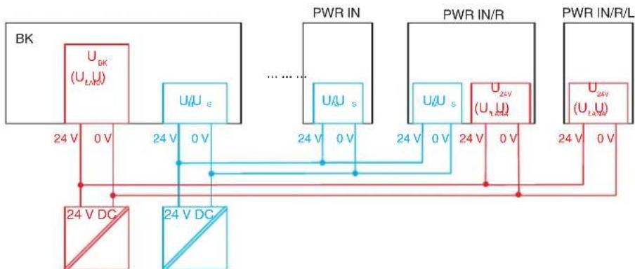
flowchart
graph TD
    BK["BK"] -->|24 V DC| A["Ground"]
    BK -->|24 V U_s| B["PWR IN"]
    BK -->|24 V U_s| C["PWR IN/R"]
    BK -->|24 V U_s| D["PWR IN/R/L"]
    A -->|0 V| B
    B -->|0 V| C
    C -->|0 V| D
    D -->|0 V| A
    style BK fill:#f9f,stroke:#333
    style PWR IN fill:#bbf,stroke:#333
    style PWR IN/R fill:#bfb,stroke:#333
    style PWR IN/R/L fill:#ffb,stroke:#333
Figure 10-6 Supply of the power terminals and boost terminals using two separate power supply units
Table 10-3 Inline power terminals and boost terminals
| TypeSupply of | ||
| U_M/U_S | U_24V(U_L, U_ANA) | |
| IB IL 24 PWR IN-PAC X - | ||
| IB IL 24 PWR IN/2-F(-D)-PAC | X - | |
| IB IL 24 PWR IN/R-PAC | XX | |
| IB IL 24 PWR IN/R/L-0.8A-PAC | - | X |
10.3.3 Supply when connecting sensors and actuators in 1-wire technology
If you are not supplying 1-wire technology sensors and actuators using the IB IL 24V-PAC or IB IL GND-PAC potential distributor terminals, these terminals must also be supplied from the power supply unit that was used to supply U_M/U_S .
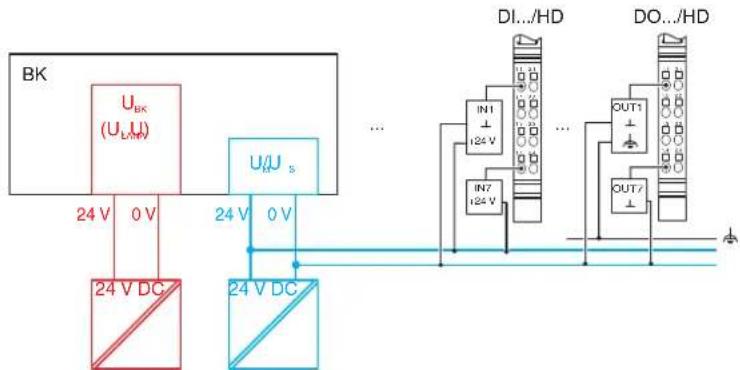
flowchart
graph TD
    A["BK"] --> B["U_BK (U_LA)"]
    B --> C["24 V DC"]
    B --> D["U/U_s"]
    D --> E["24 V DC"]
    E --> F["DI.../HD"]
    F --> G["IN1 I24 V"]
    F --> H["IN7 I24 V"]
    F --> I["OUT1"]
    F --> J["OUT/"]
    style A fill:#f9f,stroke:#333
    style B fill:#ccf,stroke:#333
    style C fill:#cfc,stroke:#333
    style D fill:#fcc,stroke:#333
    style E fill:#cff,stroke:#333
    style F fill:#ffc,stroke:#333
    style G fill:#fcc,stroke:#333
    style H fill:#fcc,stroke:#333
    style I fill:#fcc,stroke:#333
    style J fill:#fcc,stroke:#333
Figure 10-7 Supply when connecting sensors and actuators in 1-wire technology
10.3.4 Testing the supply during startup
During startup, make sure that all GND connections of the supply connectors of an Inline station are connected to GND (0 V) of the relevant power supply unit by means of measurement. For this purpose, remove all power connectors from the relevant terminals and measure the connection.
When using power terminals, make sure that they are assigned to the correct power supply unit in order not to decrease electrical isolation within the station.
10.3.5 Behavior during reset at the bus coupler, Inline controller or field multiplexer

NOTE: Malfunction
If you want to perform a reset at the head of the Inline station by switching the supply voltage off and on again, disconnect power to all I/O devices connected.
Disregarding this measure may lead to unwanted feedback.
10.4 Connecting the bus
The bus cable for your system is connected directly to the module in the case of Inline Block IO and to a bus coupler in the case of Inline Modular IO. Table 10-4 below lists the basic options for connecting the bus.
Table 10-4 Connection options for the individual fieldbus systems
| Fieldbus Connection method (to the Inline Block IO module or the Inline Modular IO bus coupler) | Connection is available | ||
| Inline Modular IO | Inline Block IO | ||
| PROFINET IO RJ | 45 female connector Yes Yes | ||
| SCRJ female connector Planned No | |||
| INTERBUS Inline | shield connector Yes Yes | ||
| 9-pos. D-SUB female connector/ 9-pos. D-SUB male connector | Yes Yes | ||
| F-SMA female connector Yes No | |||
| E2000 female connector | Yes No | ||
| PROFIBUS DP | 9-pos. D-SUB female connector | Yes Yes | |
| Ethernet/IP | RJ45 female connector Yes – | ||
| Ethernet TCP/IP | RJ45 female connector Yes Yes | ||
| Modbus/TCP RJ | 45 female connector Yes Yes | ||
| Modbus/RTU | 9-pos. D-SUB female connector | Yes | – |
| Sercos II | F-SMA female connector Yes – | ||
| Sercos III RJ45 | female connector Yes Yes | ||
| DeviceNet^TM | 2 x 5-pos. TWIN-COMBICON male connectors | Yes Yes | |
| CANopen | 2 x 5-pos. TWIN-COMBICON male connectors | Yes | No |
| 9-pos. D-SUB female connector | No | Yes | |
| Mechatrolink | USB type A | Yes – | |
| Bluetooth | Radio, antenna connection with SMA female connector | – | Yes |
Key:
Yes Connection method is available
Planned Connection method is not available at present, but is planned
No Connection method is not available at present
- No devices are available at present for this bus system

Connect the fieldbus according to the documentation for your Inline Block IO module or Inline Modular IO bus coupler.
10.5 Connecting sensors and actuators
Sensors and actuators are connected using connectors. The relevant terminal-specific data sheet indicates which connector(s) can be used for which terminal.
Connect the unshielded cables as described in Section “Connecting unshielded cables” on page 123.
Connect the shielded cables as described in Section “Connecting shielded cables using an Inline shield connector” on page 124.
10.5.1 Connection methods for sensors and actuators
Most of the digital I/O terminals in the Inline product range support the connection of sensors and actuators in 1, 2, 3 or 4-wire technology.
Because of the different types of connectors, a single connector can support the following connection methods:
- 8 sensors or actuators in 1-wire technology
- 2 sensors or actuators in 2, 3 or 4-wire technology
- 4 sensors or actuators in 2 or 3-wire technology
- 2 sensors or actuators in 2 or 3-wire technology with shield (for analog sensors or actuators)

When connecting analog devices, please refer to the terminal-specific data sheets, as the connection method for analog devices differs from that for digital devices.
10.5.2 Connections used for digital input and output terminals
Different connection options are described below using 24 V DC terminals as an example. For the 120 V AC/230 V AC area, the data changes accordingly. A connection example is provided in the relevant terminal-specific data sheet.
Table 10-5 Overview of the connections used for digital input terminals
| Connection Representation in the figure | 1-wire 2-wire 3-wire 4-wire | |||||
| S | e | n | s | o | r | s |
| Sensor supply U_S/U_M | U_S( | + | 2 | 4 | V | |
| Ground GND GND ( | ⊥) | - | - | X | ||
| Ground/FE shielding | FE ( 12 ) | - | - | - | X | |
X Used
- Not used
Table 10-6 Overview of the connections used for digital output terminals
| Connection Representation in the figure | 1-wire | 2-wire | 3-wire | 4-wire | |
| Actuator signal OUT | OUT | X | X | X | X |
| Actuator supply U_S | U_S(+24 V) | - | - | - | X |
| Ground GND GND ( | ⊥) | - | X | X | X |
| Ground/FE shielding | FE (⊥) | - | - | X | X |
X Used
- Not used

In the following diagrams, U_S is the supply voltage because this potential jumper is accessed in the majority of terminals. The relevant terminal-specific data sheet specifies whether the I/O is supplied from the main circuit U_M or the segment circuit U_S .
10.5.3 The various connection methods for sensors and actuators
1-wire technology
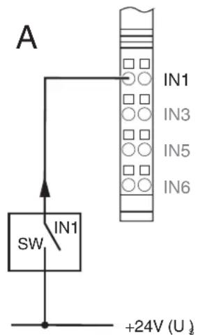

Figure 10-8 1-wire termination for digital devices
Sensor
Figure 10-9, detail A, shows the detection of a sensor signal schematically. The SW switch provides the input signal. The sensor signal is led to terminal point IN1. The sensor is supplied by the voltage U_S .

NOTE: Malfunction due to potential shifts
Supply the sensors and U_S of the Inline station from the same power supply. Make sure that there is at least one common GND as reference potential.
This will prevent potential shifts, which can have undesirable effects on the function of the station.
Actuator
Figure 10-9, detail B, shows the connection of an actuator. The actuator is supplied by output OUT1. The load is switched directly via the output.

NOTE: Malfunction due to potential shifts
Make sure that GND of the actuators and GND of the supply voltage U_S , which supply the actuators, have the same potential.
This will prevent potential shifts, which can have undesirable effects on the function of the station.

At the time of going to print, the IB IL 24 DI 32-PAC and IB IL 24 DO 32-PAC Inline terminals are designed to connect sensors and actuators in 1-wire technology. For connection examples, please refer to the corresponding data sheets.
2-wire technology
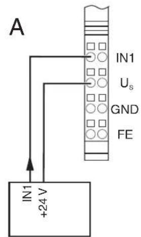
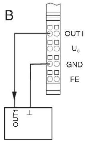
Figure 10-9 2-wire termination for digital devices
Sensor
Figure 10-9, detail A, shows the connection of a 2-wire sensor. The sensor signal is led to terminal point IN1. The sensor is supplied by the voltage U_S .
Actuator
Figure 10-9, detail B, shows the connection of an actuator. The actuator is supplied by output OUT1. The load is switched directly via the output.
3-wire technology
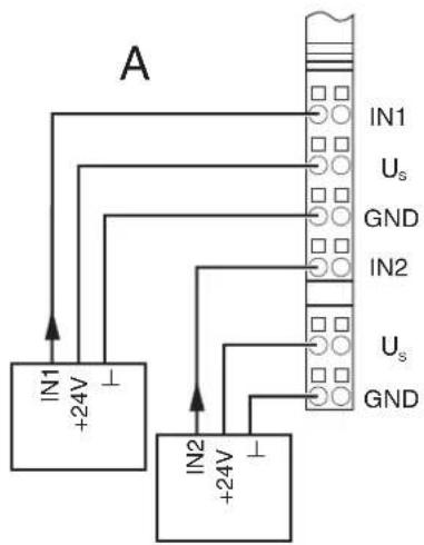
flowchart
graph TD
    A["IN1 +24V"] --> B["IN2 +24V"]
    B --> C["Grid"]
    D["IN1 Us GND"] --> C
    E["IN2 Us GND"] --> C
    F["Ground"] --> C
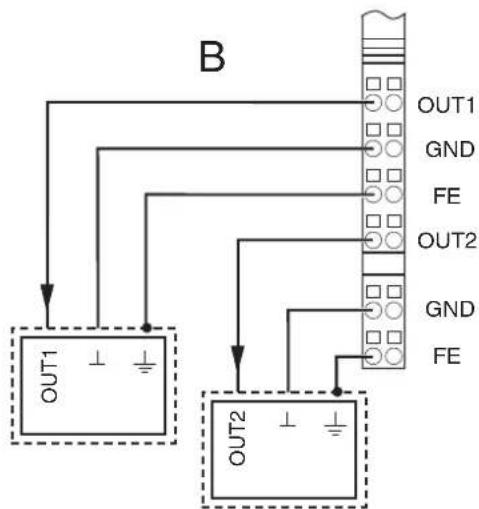
flowchart
graph TD
    A["OUT1"] --> B[" connector Block"]
    C["OUT2"] --> B
    B --> D["OUT1 GND FE"]
    B --> E["OUT2 GND FE"]
Figure 10-10 3-wire termination for digital devices
Sensor
Figure 10-10, detail A, shows the connection of a 3-wire sensor. The sensor signal is led to terminal point IN1 (IN2). The sensor is supplied via terminal points U_S and GND.
Actuator
Figure 10-10, detail B, shows the connection of a shielded actuator. The actuator is supplied by output OUT1 (OUT2). The load is switched directly via the output.
4-wire technology
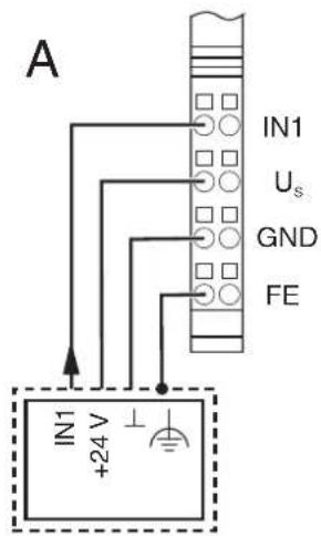
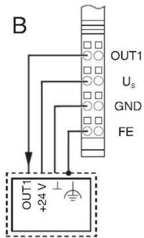
Figure 10-11 4-wire termination for digital devices
Sensor
Figure 10-11, detail A, shows the connection of a shielded 3-wire sensor. The sensor signal is led to terminal point IN1. The sensor is supplied via terminal points U_S and GND. The sensor is grounded via the FE terminal point.
Actuator
Figure 10-11, detail B, shows the connection of a shielded actuator. The provision of the supply voltage U_S means that even actuators that require a separate 24 V supply can be connected directly to the terminal.
10.6 Connections on a power-level terminal (Inline Modular IO)

WARNING: Dangerous contact voltage
Only connect and remove the connectors of a power-level terminal when the mains voltage is disconnected and cannot be switched on again.
A power-level terminal has slots for the following connections:
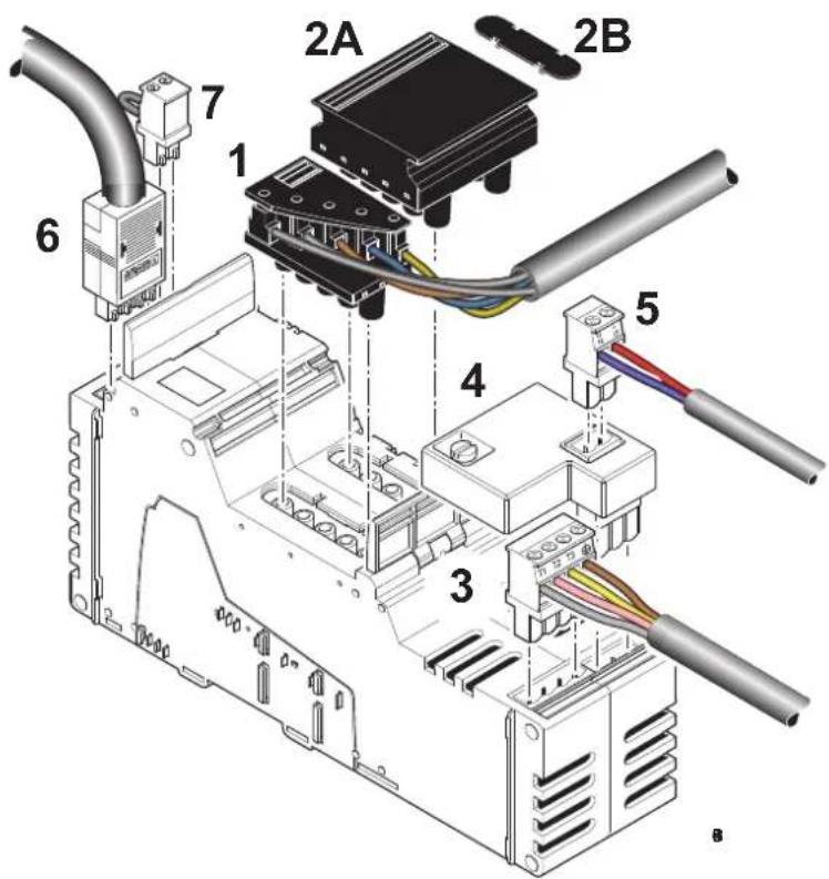
Figure 10-12 Power-level terminal with all possible connectors
Table 10-7 Slots and connectors of a power-level terminal
| No. in Figure 10-12 | Slot Connector/connection | |
| 1 X11 Incoming mains (here: power connector) | ||
| 2 X12 Outgoing mains (power bridge (2A) or cover (2B)) | ||
| 3 | X | 1 0 M o t |
| 4 | X8 | Brake module (including brake switch and connection for brake) |
| 5 | X9 | Connection of the brake to the brake module |
| 6 | X32 | Hand-held operator panel connection (hand-held operator panel mode) |
| 7 X18 Enable power level | ||
10.6.1 Connecting or forwarding the incoming mains

WARNING: Dangerous contact voltage
Only remove or insert the power connector or the power bridge when the mains voltage is disconnected.
There are two ways of connecting the incoming mains to a power-level terminal:
You can connect the incoming mains using a power connector.
When assembling the power connector, proceed as shown in Figure 10-13:
- Strip approximately 80 mm off the cable sheath (detail A) and 7 mm off the wires (detail B). Fit the wire ends with ferrules.
- Connect the wires to the connector (detail C). The assignment is shown in Figure 10-14.
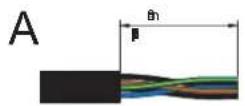
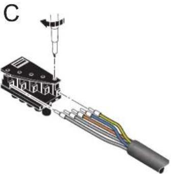
natural_image
Diagram of a mechanical assembly with colored wires and a suspended component (no text or symbols)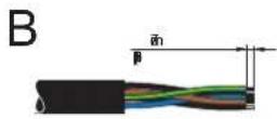
Figure 10-13 Assembling a power connector
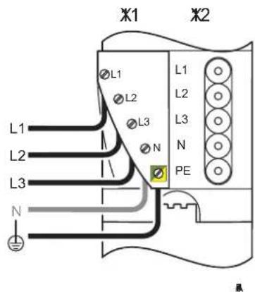
Figure 10-14 Power connector assignment
X11 Incoming mains
X12 Outgoing mains

The PEN conductor (N) is not required for power-level terminals. However, the connectors offer the option of connecting and forwarding the PEN conductor.
Insert the assembled connector into connection X11 (Figure 10-14) of the power-level terminal (Figure 10-15).
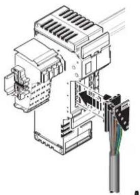
natural_image
Technical line drawing of an electrical connector assembly (no text or symbols visible)Figure 10-15 Connecting a power connector
You can forward the mains supply using a power bridge.
If several power-level terminals are connected one after the other, a power-level terminal can be connected to the preceding power-level terminal using a power bridge. If the preceding terminal is supplied with voltage, this voltage is led via the power bridge.
- Insert the power bridge on two adjacent power-level terminals so that connection X12 (outgoing mains) of the preceding terminal is connected to connection X11 (incoming mains) of the following terminal. The power bridge can carry a maximum of 20 A.
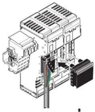
natural_image
Technical illustration of an electrical connector assembly (no text or symbols visible)Figure 10-16 Inserting a power bridge
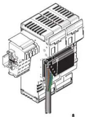
natural_image
Technical line drawing of an electrical connector assembly (no text or symbols visible)Figure 10-17 Power-level terminals with a mains connector and power bridge
10.6.2 Connecting the motor circuit connector

WARNING: Dangerous contact voltage
Only connect or remove the motor circuit connector when the mains voltage is disconnected.
The motor output is connected via a 4-pos. HV-COMBICON connector.
When assembling the motor circuit connector, proceed as shown in Figure 10-18:
- Strip approximately 30 mm off the cable sheath (detail A) and 7 mm off the wires (detail B). Fit the wire ends with ferrules.
- Connect the wires to the connector (detail C). The pin assignment is shown in Table 10-8.
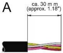
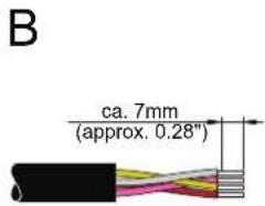
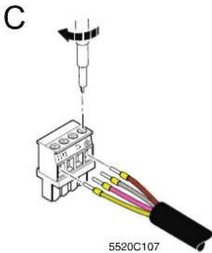
Figure 10-18 Assembling the motor circuit connector
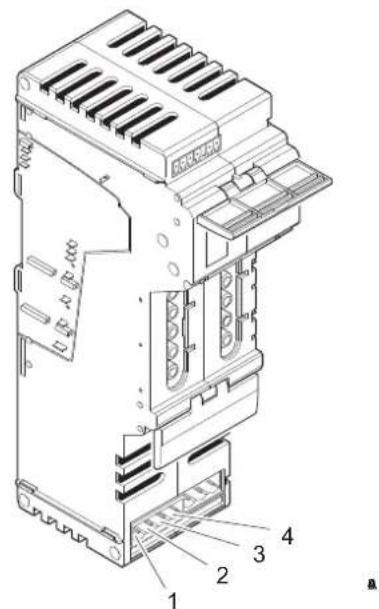
Figure 10-19 Motor output assignment
Table 10-8 Pin assignment of the motor circuit connector (HV-COMBICON)
| Pin X10 (motor) | ||
| 1 | M | o |
| 2 | M | o |
| 3 | M | o |
| 4 | M | o |
| t | o |
| t | o |
| t | o |
| : | o |
Insert the assembled connector in connection X10 (Figure 10-20).
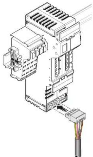
natural_image
Technical diagram of an electrical connector assembly with a cable, showing internal components and wiring (no text or labels)Figure 10-20 Inserting the motor circuit connector
10.6.3 Connecting the brake module and brake (optional)
The brake module can be used to control the brake on motors with a brake. It contains a passive semiconductor, which can be used for quick motor braking. The brake module is designed for motors with a nominal voltage of 400 V AC.
Assemble the connector for the brake as shown in Figure 10-21:
- Strip approximately 30 mm off the outer cable sheath (detail A).
- Strip approximately 7 mm off the wires (detail B).
• Fit the wire ends with ferrules and connect the wires to the connector (detail C).

Make sure that the brake is connected with the correct polarity, otherwise it may not operate correctly.
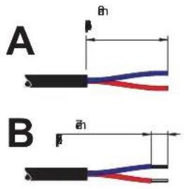
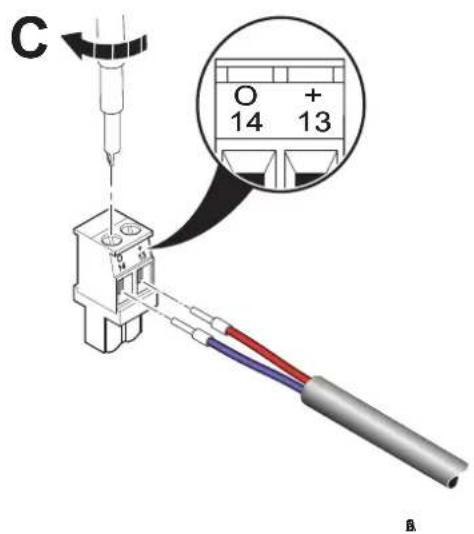
Figure 10-21 Assembling the connector for the brake
The brake module is snapped into connection X8 of a power-level terminal using a 3-pos. inverted COMBICON connector. The 2-pos. COMBICON connector for the brake is snapped into connection X9 of the brake module.
Connect the brake as shown in Figure 10-22:
- If the motor connector is plugged in, remove it. The entire module should be prepared (power-level terminal with brake module) before the I/O is connected.
- Lift up the lower release flap (detail A1).
- Snap the brake module into connection X8 (detail A2). Fasten the brake module by turning the interlocking screw (1) 90°. This secures the interlocking screw in a ventilation slot of the power-level terminal.
- Put the lower release flap down again (detail B1).
- Insert the assembled motor circuit connector into connection X10 (detail B2). (See also Section "Connecting the motor circuit connector" on page 142.)
- Insert the assembled connector for the brake into connection X9 of the brake module (detail B3).
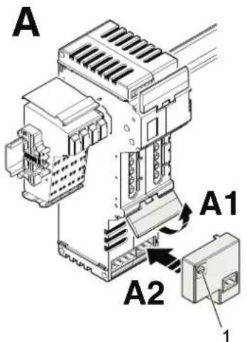
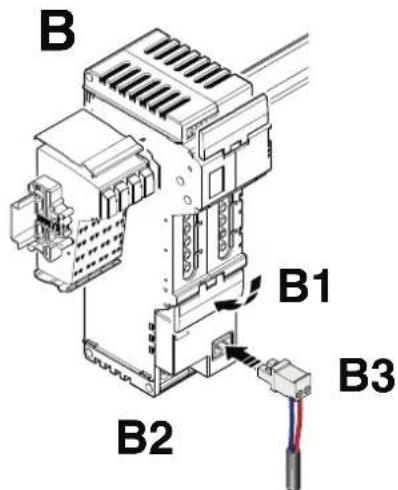
Figure 10-22 Snapping on the brake module and the connector for the brake

For additional information about the brake module, please refer to the module-specific data sheet.
10.6.4 Connecting the hand-held operator panel
Hand-held operator panel mode (manual mode) is enabled via a temporarily connected external hand-held operator panel. This panel is connected to the power-level terminal using a 4-pos. MINI-COMBICON connector. The slot is under the upper release flap (6 in Figure 10-12 on page 139). The hand-held operator panel can only be connected when the release flap is upright.

For the ordering data for the hand-held operator panel, please refer to the Phoenix Contact catalog.

For additional information about hand-held operator panel mode, please refer to the data sheets for the power-level terminals.
10.6.5 Enabling the power level/24 V isolation
The MINI-COMBICON connector for terminal strip X18 (enable power level/24 V isolation) is under the upper release flap of a power-level terminal.
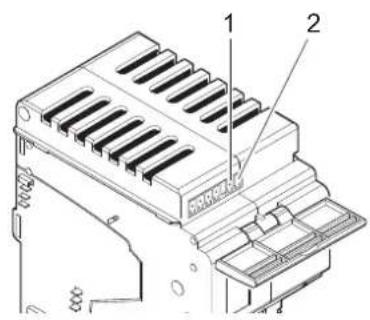
Figure 10-23 Assignment of the enable power level/24 V isolation connection
Table 10-9 Enable power level X18 (MINI-COMBICON)
| Pin X18 (enable) |
| 1 1 (24 V DC segment voltage US) |
| 2 2 (enable power level) |
The control voltage for the power level and the brake is supplied via pin 2 of the MINICOMBICON connector. The power level cannot be controlled without the 24 V control voltage.
The segment voltage U_S is used to enable the power level and can be made available using a jumper or a switch:
1 By default upon delivery, terminal strip X18 is supplied with a jumper inserted between pins 1 and 2.
If no switch is connected to X18, the jumper can remain inserted. The power level of the power-level terminal is enabled because the 24 V segment voltage is directly available.
2 If an external switch is connected between pins 1 and 2 on terminal strip X18, the power level of the power-level terminal is enabled when the switch is closed.

For additional information and safety notes, please refer to the data sheets for the power-level terminals.
11 Inline Modular IO: Technical data and ordering data

For the system data for your bus system, please refer to the corresponding documentation.
If you are using Inline in a system with other product ranges, also observe the technical data for these product ranges. Please refer to the corresponding documentation for this technical data.

The following values are standard values for the preferred mounting position (horizontal DIN rail). For different values, please refer to the terminal-specific data sheets.
The technical data does not claim to be complete. Technical modifications reserved.
11.1 Technical data for Inline Modular IO
System data
Number of devices in an Inline station 63 devices, maximum; see documentation for bus couplers
Maximum current consumption of the Inline terminals
See terminal-specific data sheet or DB GB IB IL DEVICE LIST data sheet

When configuring an Inline station, observe the power supply through the bus couplers, power terminals, and segment terminals, as well as the current consumption of each device. This information is provided in the DB GB IB IL DEVICE LIST data sheet and in the relevant terminal-specific data sheet. It can differ depending on the individual terminal. If the maximum current carrying capacity of a potential jumper is reached, a new power terminal must be used or a new station must be created.
General data

This table provides standard data. For different values, please refer to the terminal-specific data sheets.
Instructions Developed according to EN 50178/IEC 62103, UL 508
Ambient temperature
Ambient temperature (operation) - standard versions -25 °C ... +55 °C
Ambient temperature (operation) - XC version -25 °C ... +55 °C (standard)
-40 °C ... +70 °C (extended, see Section "Tested successfully: Use under extreme ambient conditions" on page 24 and the data sheet.)
Ambient temperature (operation) - ECO version 0 °C ... +55 °C
Ambient temperature (storage/transport) -25°C ... +85°C
Temperature cycles
(Speed of changing from positive to negative temperatures and vice versa)
0.5 K/min (no condensation)
Permissible humidity (operation/storage/transport) 10% ... 95% (no condensation)
The humidity requirements have been verified in accordance with IEC 60068-2-30.
Permissible air pressure (operation/storage/transport)
70 kPa ... 106 kPa (up to 3000 m above sea level)
Degree of protection IP20
General data (continued)
| Class of protection | IEC 61140 |
| Protective extra-low voltage (24 V DC ... 60 V DC, 24 V AC ... 35 V AC) | III |
| Extra-low and low voltage (>60 V DC, >35 V AC) | II (The electrical design complies with protection class II. Because the mechanical requirements for protection class II cannot be met due to the IP20 degree of protection, the devices comply with protection class II only when operated in a control box (IP54). |
| Air and creepage distances According to IEC 60644/IEC 60664A, DIN VDE 0110 and EN 50178/IEC 62103, DIN VDE 0160 | |
| Housing material Plastic, PVC-free, PA6.6, self-extinguishing (V0) | |
| Pollution degree according to EN 50178 2; condensation not permitted during operation | |
| Overvoltage category | |
| Protective extra-low voltage (24 V DC ... 60 V DC, 24 V AC ... 35 V AC) | II |
| Extra-low and low voltage (>60 V DC, >35 V AC) | III |
| Gases that may endanger functions according to DIN 40046-36, DIN 40046-37 | |
| Sulfur dioxide ( SO_2 ) Concentration 10 ±0.3 ppm | Ambient conditions- Temperature: 25°C (±2°C)- Humidity: 75% (±5%)- Test duration: 10 days |
| Hydrogen sulfide ( H_2S ) Concentration 1 ±0.3 ppm | Ambient conditions- Temperature: 25°C (±2°C)- Humidity: 75% (±5%)- Test duration: 4 days |
| Resistance of the housing material to termites Resistant | |
| Resistance of the housing material to fungal decay Resistant | |
Mechanical requirements
| Vibration test | 5g load, 2 hours in each direction |
| Sinusoidal vibrations according to IEC 60068-2-6; EN 60068-2-6 | (24 V DC, 120 V AC, and 230 V AC areas) |
| 2g load, 2 hours in each direction (400 V AC area) | |
| Shock test according to IEC 60068-2-27; EN 60068-2-27 | 25g load for 11 ms, half sinusoidal wave, three shocks in each direction and orientation |
| Broadband noise according to IEC 60068-2-64; EN 60068-2-64 | 0.78g load, 2.5 hours in each direction |
Conformance with EMC directive 2014/30/EU

This table provides standard data. For different values, please refer to the terminal-specific data sheets.
Noise immunity test according to EN 61000-6-2
| Electrostatic discharge (ESD) EN 61000-4-2/ | IEC 61000-4-2 | Criterion B6 kV contact discharge8 kV air discharge |
| Electromagnetic fields EN 61000-4-3 | IEC 61000-4-3 | Criterion AField strength: 10 V/m |
| Fast transients (burst) EN 61000-4-4/ | IEC 61000-4-4 | Criterion BRemote bus: 2 kVPower supply: 2 kVI/O cables: 2 kVCriterion AAll interfaces: 1 kV |
| Surge voltage EN 61000-4-5/ | IEC 61000-4-5 | Criterion BAC supply lines:1.0 kV/2.0 kV (symmetrical/asymmetrical)DC supply lines:0.5 kV/0.5 kV (symmetrical/asymmetrical)Signal lines:1.0 kV/1.0 kV (symmetrical/asymmetrical) |
| Conducted interference EN 61000-4-6 | IEC 61000-4-6 | Criterion ATest voltage 10 V |
Noise emission test according to EN 61000-6-4
Noise emission of housing EN 55011 Class A
Data transfer in the local bus
Protocol IEC 61158
Transmission speed 500 kbps or 2 Mbps
Transmission Inline data jumpers
24 V bus coupler supply ( U_BK )
Nominal voltage 24 V DC
Ripple ±5%
Permissible voltage range 19.2 V DC ... 30.0 V DC, ripple included
Connection Inline connectors

The communications power U_L (7.5 V) and the analog supply U_ANA (24 V) are generated from the bus coupler supply U_BK .
7.5 V supply of the bus logic ( U_L ; generated from U_BK )
Nominal voltage 7.5 V
Ripple ±5%
Load current
Maximum
Terminal-specific
See terminal-specific data sheet
2 A
0.7 A (e.g., IL IB BK-PAC)

Observe the specifications in the terminal-specific data sheet for the terminal used for power supply (U_BK) . These terminals can limit the maximum permissible load current.
Connection Inline potential jumpers
Remark
Voltage is generated in the bus coupler by a DC/DC converter from the 24 V supply voltage.
U_L is not electrically isolated from the 24 V bus coupler supply voltage.
U_L is electrically isolated from the I/O voltages U_M and U_S .
The communications power U_L is electronically short-circuit-proof.
Supply of terminals for analog signals (U ANA ; generated from U BK )
| Nominal voltage 24 V DC | |
| Tolerance -15%/+20% | |
| Ripple ±5% | |
| Permissible voltage range 19.2 V DC ... 30.0 V DC, ripple included | |
| Maximum load current 500 mA | |
| Connection Inline potential jumpers | |
| Remark Decoupling of the 24 V input voltage by means of a diode. | |
Smoothing via filter with base frequency of 9.8 kHz and attenuation of 40 dB/decade.
U_ANA is not electrically isolated from the 24 V bus coupler supply voltage and the 7.5 V communications power.
Supply of terminals for digital signals ( U_M , U_S ) in the 24 V area
| Nominal voltage 24 V DC | |
| Tolerance -15%/+20% | |
| Ripple ±5% | |
| Permissible voltage range 19.2 V DC ... 30.0 V DC, ripple included | |
| Load current at U_M (main supply) | See terminal-specific data sheet or DB GB IB IL DEVICE LIST data sheet |
| Maximum 8 A | |
| Terminal-specific 6 A (e.g., IB IL 24 PWR IN/2-F-PAC) | 4 A (e.g., IB IL 24 PWR IN/2-F-D-PAC) |
| Load current at U_S (segment supply) | See terminal-specific data sheet or DB GB IB IL DEVICE LIST data sheet |
| Maximum 8 A | |
| Terminal-specific 6 A (e.g., IB IL 24 SEG/F-PAC) | 4 A (e.g., IB IL 24 SEG/F-D-PAC)2.5 A (e.g., IB IL 24 SEG-ELF-PAC) |

Observe the specifications in the terminal-specific data sheet for the terminal used for power supply (U_M / U_S) . These terminals can limit the maximum permissible load current.
Connection to corresponding terminals for supply Inline connectors
Connection within the Inline station
Inline potential jumpers
Supply of terminals for digital signals (L) in the 120 V AC and 230 V AC areas
| Nominal voltage 120 V AC | |
| 230 V AC | |
| Tolerance -15%/+10% | |
| Ripple ±5% | |
| Permissible voltage range | 12 V AC ... 253 V AC, ripple included |
| Load current 8 A, maximum | |
| Connection Inline potential jumpers | |
Voltage dips and interrupts to the I/O supply
| Intensity PS1 Interrupt time < 1 ms | |
| Time interval between voltage dips < 1 s | |
| Behavior Evaluation criterion 1 | A dip in the supply voltage < 1 ms is not registered by the bus. |
| Intensity PS2 Interrupt time < 10 ms | |
| Time interval between voltage dips < 1 s | |
| Behavior Evaluation criterion 3 | Bus disconnection, all system outputs are reset. |
Current and voltage distribution in data and potential jumpers
| See Section “Current and voltage distribution” on page 84. | |
| Cable connection method/cross-section | |
| Cable connection method for the low-level signal and low voltage levels | Spring-cage terminals |
| Cable connection method for the power level Screw terminals | |
| Cable cross-section for the low-level signal and low voltage levels | |
| typical (solid/stranded) | 0.08 mm^2 ... 1.5 mm^2 , AWG 28 ... 16 |
| for UL approvals (solid/stranded) 0.2 mm^2 ... 1.5 mm^2 , AWG 24 ... 14 | |
| Cable cross-section for the low-level signal and low voltage levels(Connection of the protective conductor PE) | 1.5 mm^2 ; AWG 16; cable is as short as possible |
| Cable cross-section for the power level(Power connection, motor connection, brake connection)(stranded and solid cables) | 0.2 mm^2 ... 2.5 mm^2 ; AWG 28 ... 14 |
| Length of the sensor/actuator cables | |
| For digital terminals < 30 m | |
| For analog terminals | See Section "Maximum cable lengths for analog devices" on page 160 |
Electrically isolated areas
| See terminal-specific data sheets. | |||
| Air and creepage distances (according to EN 50178, VDE 0109, VDE 0110) | |||
| Isolating distance Clearance | Creepage dis- | tance | Impulse voltage withstand level |
| Technology for 24 V area | |||
| Incoming bus/bus logic | 0.3 mm | 0.3 mm | 0.5 kV |
| Outgoing bus/bus logic | 0.3 mm | 0.3 mm | 0.5 kV |
| Incoming bus/outgoing bus | 0.3 mm | 0.3 mm | 0.5 kV |
| Bus logic/I/O | 0.3 mm | 0.3 mm | 0.5 kV |
| Technology for area up to 250 V DC | |||
| Bus logic/I/O | 3.1 mm | 1.1 mm | 4 kV |
| Technology for 230 V AC area single-phase (up to 253 V AC); safe isolation according to EN 50178 | |||
| Bus logic/I/O | 5.5 mm | 5.5 mm | 6 kV |
| I/O/PE | 3.2 mm | 3.2 mm | 4 kV |
Air and creepage distances (according to EN 50178, VDE 0109, VDE 0110) (continued)
Technology for 400 V AC area three-phase; safe isolation according to EN 50178
Bus logic/400 V AC I/O 5.5 mm 3.2 mm 6 kV
24 V DC I/O/400 V AC I/O
5.5 mm
3.2 mm
6 kV
Bus logic/24 V DC I/O 0.3 mm 0.3 mm 0.5 kV
Relay outputs
Main contact/N/O contact See terminal-specific data sheet
Relay contact/bus logic See terminal-specific data sheet
Test voltages
Isolating distance Test voltage
Technology for 24 V area (up to 60 V DC)

For information about the test voltages between the bus and other potential areas, please refer to the documentation for the bus coupler.
7.5 V communications power, 24 V bus coupler supply/functional earth ground
7.5 V communications power, 24 V bus coupler supply/24 V main supply, 24 V segment supply
24 V main supply, 24 V segment supply/functional earth ground 500 V AC, 50 Hz, 1 min.
Technology for area up to 250 V DC
Bus logic/I/O 2500 V AC, 50 Hz, 1 min.
Technology for 230 V AC area single-phase (up to 253 V AC)
Bus logic/I/O 2500 V AC, 50 Hz, 1 min.
Routine test 1200 V AC, 50 Hz, 1 min.
Relay outputs
Main contact/N/O contact
Ordering data for Inline terminals and corresponding connectors
For the ordering data for the Inline terminals and corresponding connectors, please refer to the corresponding data sheet or the catalog. The catalog is available in electronic form at phoenixcontact.net/products.
Ordering data for accessories
| Description TypeOrder No. Pcs./Pkt. | |||
| Power supply units QUINT-PS ... | |||
| Keying profile IL CP 2742683 100 | |||
| Zack marker strip to label the terminals ZBF 6 ... | |||
| Zack marker strip to label the terminals ZBF 12 ... | |||
| Labeling field covering one connector IB IL FIELD 2 2727501 10 | |||
| Labeling field covering four connectors | IB IL FIELD 8 | 2727515 | 10 |
| Insert strips for IB IL FIELD 2, perforated, can be labeled using a laser printer, marker pen or CMS system (72 strips) | ESL 62X10 | 0809492 1 | |
| Insert strips for IB IL FIELD 8, perforated, can be labeled using a laser printer, marker pen or CMS system (15 strips) | ESL 62X46 | 0809502 5 | |
| DIN EN 50022 DIN rail, 2 meters | NS 35/7,5 PERFORATEDNS 35/7,5 UNPERFORATED | 08017330801681 | |
| Standard end clamp; snapped on without tools | CLIPFIX 35-5 | 3022276 | 50 |
| End clamp for CANopen and DeviceNetTM; snapped on without tools | CLIPFIX 35 | 3022218 50 | |
| End clamp for use in the event of vibrations or installation on vertical DIN rail; secured with screws | E/AL-NS 35 | 1201662 50 | |
| Screwdriver according to DIN 5264, blade width 3.5 mm (9/64 in.) | SZF 1 - 0,6 x 3,5 | 1204517 | 1 |
Ordering data for accessories: shield connection
| Description | Type | Order No. | Pcs./Pkt. |
| Shield connection clamp, for shield on busbars, contact resistance < 1 mΩ | SK 8 | 3025163 | 10 |
| Shield connection clamp, for shield on busbars, contact resistance < 1 mΩ | SK 14 | 3025176 | 10 |
| Shield connection clamp, for shield on busbars, contact resistance < 1 mΩ | SK 20 | 3025189 | 10 |
| Shield connection clamp, for shield on busbars, contact resistance < 1 mΩ | SK 35 | 3026463 | 10 |
| Support bracket for busbars | AB-SK | 3025341 | 10 |
| Support bracket, Bracket for busbars, set every 20 cm, Length: 95.5 mm, Width: 6.2 mm, Color: gray | AB-SK 65 | 3026489 | 10 |
| Support bracket, Bracket for busbars, set every 20 cm, Length: 10 mm, Width: 56 mm, Height: 20 mm, Color: silver | AB-SK/E | 3026476 | 10 |
| PEN conductor busbar, 3mm x 10 mm, length: 1000 mm | NLS-CU 3/10 SN 1000MM | 0402174 | 10 |
| Connection terminal block, Connection method Screw connection, Cross section: 0.5 mm ^2 - 6 mm ^2 , Width: 7 mm, Color: silver | AK 4 0404017 50 | ||
| Connection terminal block, Connection method Screw connection, Cross section: 0.5 mm ^2 - 6 mm ^2 , Width: 7 mm, Color: green-yellow | AKG 4 GNYE 0421029 50 | ||
| Connection terminal block, Connection method Screw connection, Cross section: 0.5 mm ^2 - 6 mm ^2 , Width: 7 mm, Color: black | AKG 4 BK 0421032 50 |
Ordering data for documentation
| Description | Type | Order No. | Pcs./Pkt. |
| "INTERBUS & AUTOMATION - Terms and definitions" user manual | IBS TERM RG UM E 2743695 1 | ||
| "Summary of key data for Inline devices" data sheet | DB GB IB IL DEVICE LIST | - | - |
| "I/O modules at bus couplers" application note | AH IL BK IO LIST | -- |

The comprehensive documentation listed above and all terminal-specific documentation can be downloaded at phoenixcontact.net/products. Make sure you always use the latest documentation.
A Appendix: Inline Modular IO: Additional information
A 1 Use of Inline terminals at an elevation of more than 3000 meters
This section applies to terminals of the Inline product group that are operated with a DC voltage of < 60 V DC.

WARNING: Dangerous contact voltage/loss of safety function
This section does not apply to the following modules or applications:
- Terminals that are not operated with PELV (Protective Extra Low Voltage) (e.g. 120 V or 230 V)
- Terminals with safety functions (e.g. SafetyBridge, Profisafe)
- Use of a safe signal path
– Use in potentially explosive areas (IEC Ex, ATEX, Hazardous Location).
- X C v a r i a n t s
In these cases, consider the individual terminal or application separately.
The Inline terminals are approved for use up to an elevation of 3000 m above sea level, see “Technical data for Inline Modular IO” on page 147.
The maximum permissible ambient temperature decreases at elevations above this level. Therefore, keep temperature derating in mind when using the terminals at an elevation greater than 3000 m up to 5000 m.
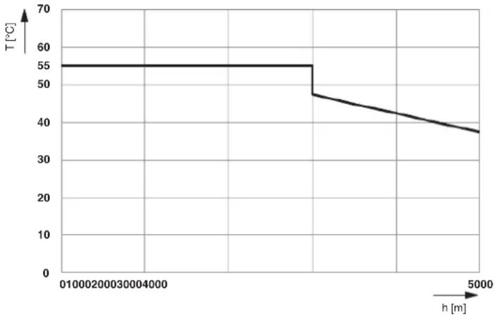
line
| h [m] | T [°C] | | ----- | ------ | | 0 | 55 | | 1000 | 55 | | 2000 | 48 | | 3000 | 45 | | 4000 | 42 | | 5000 | 38 |Figure A-1 Derating of the permissible ambient temperature depending on the operating elevation
Key:
T [°C] Maximum ambient temperature (operation) in °C
h [m] Elevation in m
A 2 Tips for working with Inline
Safe grounding
When grounding, always observe the notes in Section "Grounding concept" on page 106.
Order of the terminals
During configuration, observe the notes in Section “Order of the Inline Modular IO terminals” on page 120.
A 3 Configuration help for selecting the optimum analog input device for temperature recording
A 3.1 Inline Modular IO
Table A-1 Configuration help for selecting Inline Modular IO terminals for temperature recording (RTD)
| Criterion IB IL TEMP 2 | RTD-PAC2861328 2863915 2897402 | IB IL TEMP 4/8 RTD-PAC2702499 2702501 | IB IL TEMP 4/8 RTD/EF-PAC | IB IL RTD 4/PT100-ECO | IB IL RTD 4/PT1000-ECO | ||
| IB IL TEMP 2RTD-XC-PAC2701217 2701218 | IB IL TEMP 4/8 RTD/EF-XCPAC | ||||||
| RTD detection | RTD detection(Inputs for resistancetemperature detectors, e.g., Pt100,Pt1000, Ni100,Ni1000) | Yes Yes Yes Yes (Pt 100) Yes (Pt 1000) | |||||
| Number of RTD 2-wiresensors | 2 | 8 | 8 | 4 | 4 | ||
| Number of RTD 3-wiresensors | 2 | 8 | 8 | - | - | ||
| Number of RTD 4-wiresensors | 1 | - | 8 | - | - | ||
| Dynamic response | Dynamic response of measuring inputs | High | Very high | Low | Medium | Medium | |
| Measurements/second(typical for all channels) | 30 ... 50 | 4 ... 165 0.3 | ... 0.5 | 1.6 | 1.6 | ||
| Precision | Precision | High | Medium | Very high | Medium | Medium | |
| Typical tolerance of Pt100 or TC(at TA=+25°C) | ±0.26 K | ±0.50 K | ±0.09 K | ±0.8 K | ±0.8 K | ||
| Maximum tolerance of Pt100 or TC(at TA=+25°C) | ±1.0 K | ±2.13 K | ±0.19 K | ±1.7 K | ±1.7 K | ||
Table A-2 Configuration help for selecting Inline Modular IO terminals for temperature recording
| Criterion IB IL TEMP 2 | UTH-PAC2861386 270 | IB IL UTH 4/J-ECO2502 2702503 270 | IB IL UTH 4/K-ECO2504 | IB IL UTH 4/L-ECO | |
| IB IL TEMP 2UTH-XC-PAC2701216 | |||||
| TC detection | TC detection(Thermocouple inputs,e.g., type B, C, E, J, K, E, R, S, T,U, W, HK) | Yes Yes (type J) Yes (type K) | Yes (type L) | ||
| Number of TC 2-wire sensors 2 4 | |||||
| Internal cold junctioncompensation for thermocouple detection | Yes Yes | ||||
| Additional connection option foran external cold junction sensor(Pt1000, Ni1000) | Yes No | ||||
| Dynamic response | Dynamic response of measuring inputs | High Medium | |||
| Measurements/second(typical for all channels) | 30 | 1.6 | |||
| Precision | Precision | Medium | Medium | ||
| Typical tolerance of Pt100 or TC(at T_A =+25°C) | 0.6 K +tolerance ofcold junction(TC type K) | ±2.5 K | ±2.7 K(incl. tolerance of cold junction) | ±2.5 K | |
| Maximum tolerance of Pt100 or TC (at T_A =+25°C) | 2.4 K +tolerance ofcold junction(TC type K) | ±5.1 K | ±5.5 K | ±5.1 K | |
| (incl. tolerance of cold junction) | |||||
A 3.2 Inline Block IO
Table A-3 Configuration help for selecting Inline Block IO modules for temperature recording
| Criterion ILB IB AI4 AO2 ILB PB AI4 AO2 | |||
| 2878777 2878874 | |||
| RTD detection | RTD detection(Inputs for resistance temperature detectors, e.g., Pt100, Pt1000, Ni100, Ni1000) | Yes Yes | |
| Number of RTD 2-wire sensors 4 4 | |||
| Number of RTD 3-wire sensors 4 4 | |||
| Number of RTD 4-wire sensors 4 4 | |||
| Dynamic response | Dynamic response of measuring inputs Very high Very high | ||
| Measurements/second(typical for all channels) | 43 ... 192 43 ... 192 | ||
| Precision P | Precision High Medium | ||
| Typical tolerance of Pt100 or TC (at TA=+25°C) | ±0.3 K | ±0.5 K | |
| Maximum tolerance of Pt100 or TC (at TA=+25°C) | ±1.6 K | ±1.9 K | |
A 4 Maximum cable lengths for analog devices
A 4.1 Inline standard

Please also observe the information in the terminal-specific data sheet.
The following applies for the section below:
- The values for the maximum cable length are valid in accordance with the installation instructions and have been determined using the following reference data for the sensor or actuator cable:
Cable type LiYCY (TP)
$$ N \times 2 \times 0. 5 \text { Where: } $$
$$ N = \text { Number of wire pairs } $$
$$ 0. 5 = \text { Conductor cross - section A in mm } ^ {2} $$
Inductance 0.67 mH/km (typical)
Effective
120 nF/km (Between the wires)
capacitance

- The values in the tables also apply for versions of the specified terminal with comparable technical properties (e.g., -2MBD or non-PAC versions).
- Information about longer lengths or other cable types is available on request.
A 4.1.1 Analog input and temperature recording
Table A-4 Maximum cable lengths: Analog input
| Criterion IB IL AI2 | /SF-PAC2861302 | IB IL AI8/SF-PAC2861412 | IB IL AI8/IS-PAC2861661 | IB IL AI2/SF-230-PAC2861577 | IB IL AI4/EF-PAC2878447 | IB IL AI 4/I-PAC2700458 | IB IL AI4/U-PAC2700459 |
| Number of channels | 2 | 8 | 8 | 2 | 4 | 4 | 4 |
| Maximum cable length | 250 m | 250 m | 250 m | 250 m | 250 m | 500 m | 500 m |
Table A-5 Maximum cable lengths: Temperature recording
| Criterion | IB IL TEMP 2RTD-PAC2861328 | IB IL TEMP 4/8RTD-PAC2863915 | IB IL TEMP 4/8RTD-EF-PAC2897402 |
| Number of channels | 2 | 8 | 8 |
| Maximum cable length | 250 m^1 | 250 m^1 | 250 m |
^1 Please observe the specified tolerances for the selected connection method (2, 3 or 4-wire) (see data sheet).
A 4.2 Analog output
Table A-6 Maximum cable lengths and immunity to short-circuiting: Analog output
| Criterion IB IL AO1/SF-PAC2861315 2861399 2861467 | IB IL AO1/U/SF-PAC2700775 2863083 2878036 | IB IL AO 2/U/BP-PAC | IB IL AO 2/UI-PAC | IB IL AO 2/SF-PAC | IB IL AO4/8/U/BP-PAC | |
| Number of channels | 1 | 1 | 2 | 2 | 2 | |
| Signals | 0 V ... 10 V0 mA ... 20 mA4 mA ... 20 mA | 0 V ... 10 V | -10 V ... +10 V0 V ... 10 V | -10 V ... +10 V0 V ... 10 V0 mA ... 20 mA4 mA ... 20 mA-20 mA ... +20 mA | 0 V ... 10 V0 mA ... 20 mA4 mA ... 20 mA | -10 V ... +10 V0 V ... 10 V-5 V ... +5 V0 V ... 5 V |
| Maximum cable length | 250 m | 250 m | 500 m | 500 m | 250 m | 250 m |
| Immunity to short-circuiting of analog voltage output | Yes, 1 minute | Yes, 1 minute | Yes, 1 minute | Yes, continuous | Yes, 1 minute | Yes, 1 minute |
| Immunity to short-circuiting of analog current output | Yes, continuous | Not present | Not present | Yes, continuous | Yes, continuous | Not present |
A 4.3 Analog I/O
Table A-7 Maximum cable lengths and immunity to short-circuiting: Analog I/O
| Criterion | ILB xx AI4 AO2 |
| Number of channels for input | 4 |
| Number of channels for output | 2 |
| Signals | -10 V ... +10 V0 V ... 10 V-5 V ... +5 V0 V ... 5 V0 mA ... 20 mA-20 mA ... +20 mA4 mA ... 20 mA |
| Maximum cable length | 250 m^1 |
| Immunity to short-circuiting of analog voltage output | Yes, continuous |
| Immunity to short-circuiting of analog current output | Yes, continuous |
^1 Please observe the specified tolerances for the selected connection method (2, 3 or 4-wire) (see data sheet).
A 4.4 Inline ECO terminals

Please also observe the information in the terminal-specific data sheet.
Table A-8 Maximum cable lengths: Temperature recording
| Criterion IB IL RTD 4/PT100-ECO | IB IL RTD 4/PT1000-ECO | IB IL UTH4/J-ECO | IB IL UTH4/K-ECO | IB IL UTH4/L-ECO |
| 2702499 270 | 2501 2702502 27 | 02503 2702504 | ||
| Number of channels | 4 | 4 | 4 | |
| Cable type/standard | LiYCY(TP)N x 2 x 0 , 5 | LiYCY(TP)N x 2 x 0 , 5 | Type J according to DIN EN 60584-3 | Type K according to DIN EN 60584-3 |
| Maximum cable length | 30 m* | 100 m | 100 m | 100 m |
* Observe the cable resistances when carrying out a tolerance inspection (see terminal-specific data sheet).
Table A-9 Maximum cable lengths: Analog I/O
| Criterion | IB IL AI4/I/4-20-ECO | IB IL AI4/U/0-10-ECO | IB IL AO4/I/4-20-ECO | IB IL AO4/U/0-10-ECO |
| I2702495 | 2702496 2702497 | 2702498 | ||
| Number of channels | 4 | 4 | 4 | 4 |
| Cable type/standard | LiYCY(TP)N x 2 x 0 , 5 | LiYCY(TP)N x 2 x 0 , 5 | LiYCY(TP)N x 2 x 0 , 5 | LiYCY(TP)N x 2 x 0 , 5 |
| Maximum cable length | 100 m | 100 m | 100 m | 100 m |
Table A-10 Maximum cable lengths: Communication
| Criterion | IB IL RS 485-ECO | IB IL RS 232-ECO |
| 2702141 | 2702795 | |
| Number of channels | 1 | 1 |
| Cable type/standard | CAT5 | CAT5 |
| Maximum cable length | according to RS-485 specification | depending on the transmission speed |
A 5 Temperature response of the terminals
| Please note that derating or simultaneity limitations must be taken into consideration depending on the ambient temperature. Notes on this are provided in the terminal-specific data sheets. The terms used in the data sheets are explained below: | |
| Power dissipation of the electronics ( P_TOT ) | The power dissipation of the electronics of a terminal is calculated according to the formula provided in the terminal-specific data sheet. The calculated value must not exceed the power dissipation of the housing. |
| Power dissipation of the housing ( P_HOU ) | The power dissipation of the housing indicates the maximum power dissipation. The maximum power dissipation is specified in the terminal-specific data sheet.In the permissible operating temperature range, the power dissipation of the housing can be dependent on or independent of the ambient temperature.If the power dissipation of the housing depends on the ambient temperature, a permissible working point must be defined. |
| Permissible working point | Depending on the power dissipation of the housing and the power dissipation of the electronics at a certain current, the maximum temperature at which the terminal can be operated with this current can be calculated. |
| Examples | Examples for calculating these values can be found in the section below. |
A 6 Calculation examples for power dissipation and working points
A 6.1 Constant power dissipation of the housing over the operating temperature range
This calculation is illustrated using the IB IL 24 DO 8-PAC terminal as an example.
Formula to calculate the power dissipation of the electronics
This formula is terminal-specific and is provided in every data sheet.
$$ P _ {T O T} = 0. 1 9 \mathrm{W} + \sum_ {\mathrm{i} = 1} ^ {\mathrm{n}} (0. 1 0 \mathrm{W} + \mathrm{I} _ {\mathrm{Li}} ^ {2} \times 0. 4 0 \Omega) $$
Where
P_TOT Total power dissipation of the electronics
i l n d e x
n Number of set outputs (n = 1 to 8)
I_Li Load current of output i

If no output is set, the component with the sigma sign is omitted.
Example: Load currents of the outputs:
$$ I _ {L 1} = 0. 5 \mathrm{A}, I _ {L 2} = 0. 4 \mathrm{A}, I _ {L 3} = 0. 2 \mathrm{A}, I _ {L 4} = 0. 5 \mathrm{A}, I _ {L 5} = 0. 3 \mathrm{A}, I _ {L 6} = 0. 4 \mathrm{A} $$
Outputs 7 and 8 are not used.
Power dissipation of the electronics According to the formula, the electronics of this specific configuration has the following power dissipation:
$$ P _ {T O T} = 0. 1 9 \mathrm{W} + [ 0. 1 \mathrm{W} + (0. 5 \mathrm{A}) ^ {2} \times 0. 4 \Omega ] $$
$$ + [ 0. 1 \mathrm{W} + (0. 4 \mathrm{A}) ^ {2} \times 0. 4 \Omega ] $$
$$ + [ 0. 1 \mathrm{W} + (0. 2 \mathrm{A}) ^ {2} \times 0. 4 \Omega ] $$
$$ + [ 0. 1 \mathrm{W} + (0. 5 \mathrm{A}) ^ {2} \times 0. 4 \Omega ] $$
$$ + [ 0. 1 \mathrm{W} + (0. 3 \mathrm{A}) ^ {2} \times 0. 4 \Omega ] $$
$$ + [ 0. 1 \mathrm{W} + (0. 4 \mathrm{A}) ^ {2} \times 0. 4 \Omega ] $$
$$ P _ {T O T} = 0. 1 9 \mathrm{W} + 0. 2 0 0 \mathrm{W} + 0. 1 6 4 \mathrm{W} + 0. 1 1 6 \mathrm{W} $$
$$ + 0. 2 0 0 \mathrm{W} + 0. 1 3 6 \mathrm{W} + 0. 1 6 4 \mathrm{W} $$
$$ P _ {T O T} = 1. 3 7 \mathrm{W} $$
| Power dissipation of the housing | The value for the power dissipation of the housing is specified in every terminal-specific data sheet.The power dissipation of the housing for the specified terminal is 2.7 W within the operating temperature range of -25°C to +55°C. The calculated power dissipation for the electronics therefore does not exceed the permissible upper limit. |
| Maximum load | Even with the maximum permissible load current (0.5 A per channel), the upper limit of 2.7 W is not exceeded within the permissible temperature range of -25°C to +55°C. P_TOT = 0.19 W + 8 × [0.1 W + (0.5 A)^2 × 0.4 ] P_TOT = 1.79 W |
A 6.2 Power dissipation of the housing within the operating temperature range depending on the ambient temperature
This calculation is illustrated using the IB IL 24 DO 2-2A-PAC terminal as an example.
Formula to calculate the power dissipation of the electronics
This formula is terminal-specific and is provided in every data sheet.
$$ P _ {T O T} = 0. 1 8 \mathrm{W} + \sum_ {\mathrm{i} = 1} ^ {\mathrm{n}} (0. 2 0 \mathrm{W} + \mathrm{I} _ {\mathrm{Li}} ^ {2} \times 0. 1 0 \Omega) $$
Where
P_TOT Total power dissipation of the electronics
i l n d e x
n Number of set outputs (n = 1 to 2)
I_Li Load current of output i

If no output is set, the component with the sigma sign is omitted.
Example:
Both outputs are enabled and operating at full load. The load currents of the outputs are I_L1 = I_L2 = 2 A .
Power dissipation of the electronics
According to the formula, the electronics of this specific configuration has the following power dissipation:
$$ P _ {T O T} = 0. 1 8 \mathrm{W} + 2 \times [ 0. 2 0 \mathrm{W} + (2 \mathrm{A}) ^ {2} \times 0. 1 0 \Omega ] $$
$$ P _ {T O T} = 0. 1 8 \mathrm{W} + 2 \times 0. 6 \mathrm{W} $$
$$ P _ {T O T} = 0. 1 8 \mathrm{W} + 1. 2 0 \mathrm{W} $$
$$ P _ {T O T} = 1. 3 8 \mathrm{W} $$
Power dissipation of the housing
The value for the power dissipation of the housing is specified in every terminal-specific data sheet.
The permissible power dissipation of the housing for the IB IL 24 DO 2-2A-PAC terminal depends on the temperature.
$$ P _ {H O U} = 2. 4 \mathrm{W} - 2 5 ^ {\circ} \mathrm{C} < T \quad A \leq - 5 ^ {\circ} \mathrm{C} $$
$$ P _ {H O U} = 2. 4 \mathrm{W} - \left[ \left(T _ {\mathrm{A}} - (- 5 ^ {\circ} \mathrm{C})\right) / 3 7. 5 ^ {\circ} \mathrm{C} / \mathrm{W} \right] - 5 ^ {\circ} \mathrm{C} < T \quad A \leq + 5 5 ^ {\circ} \mathrm{C} $$
Where
P_HOU Power dissipation of the housing
T_A Ambient temperature
At an ambient temperature of up to -5^ , you can load the housing with the maximum power dissipation.
Permissible working point
At an increased ambient temperature, you must calculate the permissible working point for the calculated power dissipation.
To do this set P_TOT = P_HOU .
$$ P _ {T O T} = 2. 4 \mathrm{W} - \left[ \left(T _ {\mathrm{A}} + 5 ^ {\circ} \mathrm{C}\right) / 3 7. 5 ^ {\circ} \mathrm{C} / \mathrm{W} \right] $$
After changing the formula, the maximum permissible ambient temperature, with this load, is calculated as:
$$ T _ {A} = (2. 4 \mathrm{W} - P _ {\text { T O T }}) \times 3 7. 5 ^ {\circ} \mathrm{C} / \mathrm{W} - 5 ^ {\circ} \mathrm{C} $$
P_TOT = 1.38 W (from the calculation for the power dissipation of the electronics)
$$ T _ {A} = (2. 4 \mathrm{W} - 1. 3 8 \mathrm{W}) \times 3 7. 5 ^ {\circ} \mathrm{C} / \mathrm{W} - 5 ^ {\circ} \mathrm{C} $$
$$ T _ {A} = 1. 0 2 \mathrm{W} \times 3 7. 5 ^ {\circ} \mathrm{C} / \mathrm{W} - 5 ^ {\circ} \mathrm{C} $$
$$ T _ {A} = 3 3. 2 5 ^ {\circ} C $$
With both outputs at full load, this terminal can be operated up to an ambient temperature of 33^ C.
If you never operate the outputs simultaneously and if a set output consumes a current of 2 A, you can operate up to an ambient temperature of:
$$ P _ {T O T} = 0. 1 8 \mathrm{W} + [ 0. 2 0 \mathrm{W} + (2 \mathrm{A}) ^ {2} \times 0. 1 0 \Omega ] $$
$$ P _ {T O T} = 0. 1 8 \mathrm{W} + 0. 6 0 \mathrm{W} $$
$$ P _ {T O T} = 0. 7 8 \mathrm{W} $$
$$ T _ {A} = (2. 4 W - P _ {T O T}) \times 3 7. 5 ^ {\circ} C / W - 5 ^ {\circ} C $$
P_TOT = 0.78 W (from the calculation for the power dissipation of the electronics)
$$ T _ {A} = (2. 4 \mathrm{W} - 0. 7 8 \mathrm{W}) \times 3 7. 5 ^ {\circ} \mathrm{C} / \mathrm{W} - 5 ^ {\circ} \mathrm{C} $$
$$ T _ {A} = 1. 6 2 W \times 3 7. 5 ^ {\circ} C / W - 5 ^ {\circ} C $$
$$ T _ {A} = 5 5. 7 5 ^ {\circ} C $$
T_A=55^ (maximum permissible ambient temperature)
As the maximum permissible ambient temperature is 55^ C, you can operate under the conditions specified above in the entire permissible temperature range. This results in a simultaneity of 50% at 55^ C as specified in the data sheet.
B Appendix: Software support
B 1 Overview of the software
From the planning phase through to system servicing, our software solutions guide you through every stage of the value added chain of an automation solution.
The software tools from Phoenix Contact are perfectly designed to work together, have a modular design, and are based on international standards, which means that even complex applications can be implemented easily.
Software can be used to perform the following tasks:
– Automated planning and configuration of Inline stations: Project+
- Planning, configuration, and labeling of Inline stations (terminal strips): CLIP PROJECT
- Network and device configuration: PC WorX, Config+, AutomationXplorer+, CMD
- Application programming: PC WorX, programming blocks, Steeplechase VLC
- System visualization: Visu+, AX OPC Server
- System diagnostics: Diag+
B 2 Project+
The Project+ program (Order no. 2988867) enables easy selection and configuration of an Inline station via a Windows user interface.
Rules for creating an Inline station and technical data for the available Inline and Fieldline products are stored in the Project+ software. Project+ thus provides comprehensive support during configuration, which means that the user does not have to have extensive knowledge of the product range. For example, you have the option of selecting functions according to your application. Based on this, the software creates a suggested Inline station, which meets the selected conditions and the system conditions (e.g., for maximum current carrying capacity).

NOTE:
Please note that software can only provide support. The design engineer is responsible for ensuring that the configuration is correct.
The tool offers the following functions:
- Generation of an Inline station consisting of Inline and Fieldline products
-
Tool support with current monitoring and autocorrect function
-
Required additional terminals are inserted automatically (e.g., additional power terminals)
– Terminals are positioned in the recommended order - Notes can be added to channels
- Immediate color visualization of the created Inline station
– Specification of the current consumption and station width
– Specification of Fieldline system cables and cable lengths
- Display of technical data, such as width, data width, cycle time, current consumption of the station
– Data transfer, e.g., to CLIP PROJECT, MS Word, MS Excel, programming tools
– Data transfer to the e-shop via the clipboard in order to generate orders
– Documentation options (project notes) - Generation of price information (if a price list is loaded)
– Export and import of release lists
B 3 CLIP PROJECT

Additional information can be found in the latest catalog or on the Internet atphoenixcontact.net/products.
The CLIP PROJECT program enables easy selection, configuration, and ordering of Phoenix Contact products and complete terminal strips via a Windows user interface. The tool offers the following functions:
- Intelligent product selection with photo support
- Configuration of terminal strips including logic tests
- Immediate color visualization of the created terminal strip
- Autocorrect function, whereby the cover, end clamp, and separating disks are positioned automatically
- Generation of parts lists, CAD drawings, and labeling data
– Data output to a printer, plotter or file - Data output in AutoCAD.dxf format
- Data transfer to MS Excel and MS Word
- CSV interface for data exchange with another CAE system
- Management of custom databases and material numbers
B 4 Other software
The other software tools listed in Section "Overview of the software" on page 169 are generally designed to configure, program, visualize, and diagnose automation products from Phoenix Contact. Therefore, they are not described in the scope of this user manual for Inline.

Additional information can be found in the latest catalog or on the Internet at phoenixcontact.net/products.
C Appendix: Explanation of abbreviations and symbols
C 1 Explanation of abbreviations
Ground Ground, general symbol

FE Functional earth ground

Noiseless ground
This ground is free from external noise voltage, and is used to ground cable shields and to suppress noise and interference voltages.
Functional earth ground is a low-impedance current path between circuits and ground. It is not designed as a safety measure but rather, for example, for the improvement of noise immunity (EN 61131).
This ground connection must be separated from parts with hazardous voltage by means of double or reinforced insulation (EN 60950).
PE Protective earth ground

This ground is used to ground devices. It also provides shock protection for people.
Protective earth ground is a low-impedance current path that minimizes the risk to the user in the event of an error (EN 61131).
GND 0 V ground; housing or chassis

In this user manual the term ground refers to common voltage return lines. Ground is electrically isolated from FE and PE. If a jumper is placed between ground and FE or PE, this isolation is removed.
Various additions to GND (such as F-GND, BC-GND, etc.) indicate separate potentials.
U_BK
Bus coupler supply
The voltage U_BK is used to supply the bus coupler power supply unit. In the power supply unit, the communications power U_L and the analog voltage U_ANA are generated from the voltage U_BK .
U_M
Main supply (I/O supply in the main circuit)
The voltage U_M supplies all of the devices connected to the main circuit.
The voltage U_M is supplied using a bus coupler or a power terminal and is led through the potential jumper to the next power terminal. (Exception: terminal with a relay output interrupts the potential jumper)
IL SYS INST UM E
| U_S | Segment supply (I/O supply in the segment circuit) |
| The voltage U_S supplies all of the devices connected to the segment circuit. | |
| The voltage U_S is supplied using a bus coupler or a power terminal or is tapped from the main voltage U_M at the bus coupler, a power terminal or a segment terminal and is led through the potential jumper to the next power or segment terminal. (Exception: terminal with a relay output interrupts the potential jumper) | |
| U_ANA | I/O supply for analog terminals |
| The voltage U_ANA is used to supply all the terminals for analog signals. | |
| It is generated in the bus coupler or in a special power terminal and is led through the Inline station by means of potential routing. | |
| U_L | Communications power |
| The voltage U_L is used to supply all the devices with communications power (supply of the module electronics). | |
| It is generated in the bus coupler or in a special power terminal and is led through the Inline station by means of potential routing. | |
| P_TOT | Power dissipation of the electronics |
| P_HOU | Power dissipation of the housing |
C 2 Representations used in basic circuit diagrams
| Local bus (INTERBUS) | This designation represents the data jumpers for the local bus (two jumpers) (sometimes still called INTERBUS). |
| U_L | This designation represents the following potential jumpers:– C o m m u n _L i) c a t i o n s p o w e r (U– Communications power ground ( U_L )– Supply voltage for analog terminals ( U_ANA ) |
| U_ANA | Supply voltage for analog terminals |
| U_S | +24 V DC segment voltage |
| U_M | +24 V DC main voltage |
L Phase in the 120 V AC or 230 V AC voltage area
N Neutral conductor in the 120 V AC or 230 V AC voltage area
C 3 Frequently used symbols
Earth, ground, and equipotentials
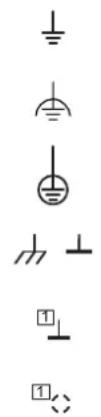
Ground, general symbol
Noiseless ground, functional earth ground (FE)
Protective earth ground (PE)
Ground, housing (GND)
Ground
In basic circuit diagrams: Different markings indicate the electrical isolations.
Shield
In basic circuit diagrams: Different markings indicate the electrical isolations.
Inputs, outputs, and other connections
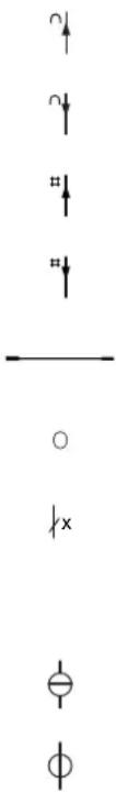
Analog input
Analog output
Digital input
Digital output
Potential or data jumper with jumper contacts on the side
Terminal point
Cable(s); x indicates the number of cables
Ideal circuits

Ideal current source
Ideal voltage source


Resistors, capacitors, and inductors
Resistor, general symbol
Capacitor, general symbol
Semiconductors


Semiconductor diode, general symbol
LED, general symbol
In basic circuit diagram: Diagnostic and status indicators on the terminals

PNP transistor

NPN transistor (note: the general symbol for transistor (see above) is sometimes also used for NPN-wired terminals)
Miscellaneous

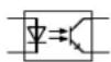
Protocol chip
(Bus logic including voltage conditioning)

Optocoupler

Converter, general symbol

Analog/digital converter

Digital/analog converter

Coupler with electrical isolation
Power supply unit with electrical isolation, general symbol

Coupling network
Amplifier

Electrically isolated area

Fuse
D Appendix: Index
Numerics
1-wire technology.... 136
24 V isolation.... 146
2-wire technology.... 137
3-wire technology.... 137
4-wire technology.... 138
A
AC terminals 15
Accessory terminal.... 29, 34
Additional functional earth grounding Bus coupler .... 107 Power terminal .... 32, 106
Air and creepage distances.... 151
Analog circuit 74
Analog terminals, positioning 121
Application notes 10
B
Basic circuit diagram Explanation of symbols .... 174
BK IO LIST.... 10
Brake 144
Brake module....144
Bus connection 13
Bus coupler....24 Additional functional earth grounding ....107 Diagnostic and status indicators....87
Bus systems IL....28 ILB....46
C
Cable connection method 151
Cable cross-section 151
Circuit diagram, example 78
Circuits....73
Connecting cables Shielded .... 124 Unshielded .... 123
Connecting shielded cables.... 124
Connecting unshielded cables.... 123
Connection method.... 134
1-wire technology.... 136
2-wire technology.... 137
3-wire technology.... 137
4-wire technology.... 138
Connector 120 V AC/230 V AC internal jumpering.... 68
120 V AC/230 V AC special features.... 67
120 V AC/230 V AC types 67
24 V DC identification.... 66
24 V DC internal jumpering.... 66
24 V DC types 65
Colors.... 63
Dimensions 64
Special features of 120 V AC/230 V AC terminal points 68
Structure.... 49,60
Terminal point 69
Types 65, 67
Width.... 63
Control box .... 100 See also Terminal box
Control cabinet.... 100
Control terminal.... 42
D
Data formats IL, I/O terminals .... 37 ILB.... 47
Data routing 82, 84, 85
Data sheets.... 10
Data transfer 149
Diagnostic and status indicators 87 Bus coupler 87
I/O (ILB)....96
I/O terminals....90
Power and segment terminals 89
Power-level terminals.... 93
Supply (ILB) 95
Diagnostics Extended.... 87
IL 37
ILB....47
Dimensions
Connector....64
ILB....62
Low-level signal/low voltage.... 54
Power housing.... 59
DIN rail 100, 101
Documentation landscape 9
E
Electronic module (ILB)....60
Dimensions 62
Structure....60
Electronics base (IL) 50
Dimensions 54-59
Structure.... 49
EMC directive.... 148
Enable power level.... 146
End clamp (IL).... 111
End plate (IL).... 111
Errors, diagnostics 87
ESD 99
EX ZONE 2 10
F
FE 82
See also Functional earth ground/grounding
FE spring....82
Function identification
IL 53
ILB....61
Functional earth ground 106
Functional earth grounding
I/O terminals.... 36
Power terminals.... 32
Segment terminals 33
Functions
IL I/O....36
ILB....46
G
GND....82
Grounding
Functional earth grounding.... 106
Grounding concept.... 106
I/O terminals.... 36
ILB....47
Protective earth grounding 106
See also Protective earth grounding
Guideways.... 50
H
Hand-held operator panel mode 145
Housing dimensions
ILB....62
Low-level signal/low voltage.... 54
Power....59
|
I/O (IL)
Diagnostic and status indicators.... 96
I/O connection.... 13
I/O terminals (IL)
Diagnostic and status indicators.... 90
Grounding 36
Protection.... 36
Inline
Mounting location.... 12
Product description 12
Terminal versions.... 12
Inline Block IO
Basic structure 60
Housing dimensions.... 62
Inline connector
Basic structure 63
Labeling 69
Numbering 69
Inline station
Example 45
Order of the terminals.... 120
Installation
Instructions....99
IP20 100
K
Keyway/featherkey connection 52
L
Labeling 70
Latching 50
Lieferumfang.... 25
Local bus transmission speed Identification....54
Locking clips 50
Logic circuit....74
Low voltage.... 15
Low voltage terminals See Low-level signal/low voltage terminals
Low-level signal and low voltage terminals Control terminal.... 42
Low-level signal housing.... 19
Low-level signal/low voltage terminals AC terminals..... 15
Accessory terminals 34
Basic structure.... 49
Housing dimensions.... 54
Power terminals.... 31
Segment terminals 33
Terminals with remote bus branch.... 28
Voltage areas 15
M
Main circuit....75
Mains voltage for power-level terminals 77
Manual mode 145
Mechanical requirements.... 148
Motor circuit connector.... 142
Mounting.... 12 Distances .... 101–104
IL, low-level signal/low voltage 112
IL, power-level terminals.... 117
ILB....119
Location.... 100
Mounting position.... 100
O
Order of the Inline terminals 120
P
Package slips.... 10
Parameterization IL....37 ILB....47
PE 83 See also Protective earth ground/grounding
Potential and data routing .... 50 Arrangement of jumpers.... 80
See also Data routing See also Potential routing
Potential routing Analog circuit.... 74
Current and voltage distribution.... 84
Current carrying capacity 82
FE.... 82,106
FE spring....82
GND 82
Logic circuit 74
Main circuit.... 75
PE 83
Segment circuit 76
Power bridge.... 52, 141
Power connector 120 V AC/230 V AC.... 68 24 V DC.... 67 Power-level terminals.... 52, 140
Power dissipation Calculation example.... 164
Electronics 163
Housing.... 163
Working point 163
Power supply ILB....46
Power terminal.... 29, 31 Additional functional earth grounding .... 32, 106
Diagnostic indicators.... 89
Electrical isolation 32
Protective earth grounding 108
Voltage areas 31
Power-level terminal 15,38
Connections 38,139
Positioning.... 121
Protective earth grounding 108
Power-level terminals.... 38
Basic structure 51
Housing dimensions.... 59
Programmable terminals.... 42
IL SYS INST UM E
Protection
IL, I/O....36
ILB....46
Protective earth ground.... 108
Protective earth grounding.... 32
120 V AC/230 V AC power terminal.... 108
I/O terminals.... 36
Power-level terminals 38, 108
Q
Quick Start Guide....9
R
Release flaps 52
Remote bus branch, positioning.... 121
Removal
IL, low-level signal/low voltage 113
IL, power-level terminals.... 118
ILB....119
Replacing a fuse 116
S
Safety-related segment circuit.... 10
Scope of supply
ILB....46
Segment circuit 33,76
Segment terminal.... 29, 33
Diagnostic indicators.... 89
Functional earth grounding.... 33
Segmentation.... 33
SELV....15
Servo amplifier 38
Shielding.... 109
Analog sensors and actuators.... 109
Concept....109
Connecting the shield.... 124
IL 37
ILB....47
Shield connection clamp 127
Slot....69
Snap-on mechanism....50
Status indicators
See also Diagnostic and status indicators
Structure
Connector 49,60
Electronic module (ILB).... 60
Electronics base (IL).... 49
Inline Block IO 60
Inline connector....63
Low-level signal/low voltage terminals 49
Power-level terminals.... 51
Supply terminals
Accessory terminal.... 34
Power terminal 31
Segment terminal 33
Supply voltages 73
Bus coupler 73
System data.... 147
T
Temperature response.... 163
Terminal box 100
Terminal point 69
Terminal point numbering 69
Terminals for analog signals, positioning .... 121
Terminals with remote bus branch 28
Test voltages 152
Transmission speed.... 26
U
User manual....9
V
Voltage areas.... 15, 31
IL I/O 37
ILB....46
W
Working point.... 163
Calculation example.... 164
E Appendix: Revision history
Table E-1 Revision history
| Revision Date Contents | |||
| B 01/2003 | First publication | ||
| 02 07/2008 | Completely revised- Inline Block IO added- Adaptation to current product portfolio | ||
| 03 | 11/2013 | Addition of Section 10.3 | Recommendation for supplying the supply voltage and resetting the voltage with regard to Inline Modular |
| Additions to Section 11.1 | Cable connection method/cross section:Cross section for the low-signal and low-voltage levels for UL approvals-A W G v a l u e s a d d e d | ||
| 04 02/2015 | Correction to Section 11.1 | Surge voltage | |
| 05 11/2016 | Addition | XC versions, | ECO versions |
| Revision of Section 4.2.9 | Updating of safety modules | ||
| Correction in Section 4.2.10 | Correction of description | ||
| Correction in Section 5.1.7.1 | Correction of dimensions, addition of BK housing | ||
| Correction in Section 9.5.2 | FE -> PE | ||
| Addition of Section 10.1.3 | Connecting shielded cables using an Inline connector | ||
| Correction/additions in Section 11.1 | - Added ECO and XC ambient temperatures- Changed information on humidity- Corrected information on the protection class- Corrected information on the overvoltage category- Updated EMC directive | ||
| Additions to Section 11.2 | Ordering data for accessories for connecting the shielding using an Inline connector | ||
| Additions to Appendix A2 | New items added to tables | ||
| 06 | 2017-02-22 | Additions to Appendix A | A1: Use of Inline terminals at an elevation of more than 3000 meters |
| 07 2017-03-07 | Correction in Section 11.1 | Information on humidity | |
| 08 2017-04-25 | Additions to Section 11.1 | Information on humidity | |