PLC-V8C/PT-24DC/EM - Uncategorized Phoenix - Free user manual and instructions
Find the device manual for free PLC-V8C/PT-24DC/EM Phoenix in PDF.


User questions about PLC-V8C/PT-24DC/EM Phoenix
0 question about this device. Answer the ones you know or ask your own.
Ask a new question about this device
Download the instructions for your Uncategorized in PDF format for free! Find your manual PLC-V8C/PT-24DC/EM - Phoenix and take your electronic device back in hand. On this page are published all the documents necessary for the use of your device. PLC-V8C/PT-24DC/EM by Phoenix.
USER MANUAL PLC-V8C/PT-24DC/EM Phoenix
text_image
PLC logic PLC-VMCPT-24DC5M PLC-VMCPT-34DC5M PLC logic PLC-VMCPT-34DC5M PLC logic PLC-VMCPT-34DC5M PLC logic PLC-VMCPT-34DC5M PLC logic PLC-VMCPT-34DC5M PLC logic PLC-VMCPT-34DC5M PLC logic PLC-VMCPT-34DC5M RLS RS IN/OUT 6 IN/OUT 8 IN/OUT 10 IN/OUT 12 IN/OUT 14 IN/OUT 16 IN/OUT 18 IN/OUT 20 IN/OUT 22 IN/OUT 24 IN/OUT 26 IN/OUT 28 IN/OUT 30 IN/OUT 32 IN/OUT 34 IN/OUT 36 IN/OUT 38 IN/OUT 40 IN/OUT 42 IN/OUT 44 IN/OUT 46 IN/OUT 48 IN/OUT 50 IN/OUT 52 IN/OUT 54 IN/OUT 56 IN/OUT 58 IN/OUT 60 IN/OUT 62 IN/OUT 64 IN/OUT 66 IN/OUT 68 IN/OUT 70 IN/OUT 72 IN/OUT 74 IN/OUT 76 IN/OUT 78 IN/OUT 80 IN/OUT 82 IN/OUT 84 IN/OUT 86 IN/OUT 88 IN/OUT 90 IN/OUT 92 IN/OUT 94 IN/OUT 96 IN/OUT 98 IN/OUT 100Installing and operating the PLC logic programmable logic relay system
User manual
User manual
Installing and operating the PLC logic programmable logic relay system
2016-12-15
Designation: UM EN PLC logic
Revision: 01
Order No.: —
This user manual is valid for:
Designation Order No.
PLC-V8C/SC-24DC/BM 2903094
PLC-V8C/PT-24DC/BM 2905135
PLC-V8C/SC-24DC/BM2 2907447
PLC-V8C/PT-24DC/BM2 2907446
PLC-V8C/SC-24DC/EM 2903095
PLC-V8C/PT-24DC/EM 2905137
PLC-V8C/SC-24DC/SAM 2905082
PLC-V8C/PT-24DC/SAM 2905136
PLC-V8C/SC-24DC/SAM2 2907445
PLC-V8C/PT-24DC/SAM2 2907443
LOGIC+ software
PLC logic app software
Please observe the following notes
User group of this manual
The use of products described in this manual is oriented exclusively to:
– Qualified electricians or persons instructed by them, who are familiar with applicable standards and other regulations regarding electrical engineering and, in particular, the relevant safety concepts.
- Qualified application programmers and software engineers, who are familiar with the safety concepts of automation technology and applicable standards.
Explanation of symbols used and signal words

This is the safety alert symbol. It is used to alert you to potential personal injury hazards. Obey all safety measures that follow this symbol to avoid possible injury or death.
There are three different categories of personal injury that are indicated with a signal word.
DANGER This indicates a hazardous situation which, if not avoided, will result in death or serious injury.
WARNING This indicates a hazardous situation which, if not avoided, could result in death or serious injury.
CAUTION This indicates a hazardous situation which, if not avoided, could result in minor or moderate injury.

This symbol together with the signal word NOTE and the accompanying text alert the reader to a situation which may cause damage or malfunction to the device, hardware/software, or surrounding property.

This symbol and the accompanying text provide the reader with additional information or refer to detailed sources of information.
How to contact us
Internet
Up-to-date information on Phoenix Contact products and our Terms and Conditions can be found on the Internet at: phoenixcontact.com
Make sure you always use the latest documentation. It can be downloaded at: phoenixcontact.net/products
Subsidiaries
If there are any problems that cannot be solved using the documentation, please contact your Phoenix Contact subsidiary. Subsidiary contact information is available at phoenixcontact.com.
Published by PHOENIX CONTACT GmbH & Co. KG
Should you have any suggestions or recommendations for improvement of the contents and layout of our manuals, please send your comments to: tecdoc@phoenixcontact.com
General terms and conditions of use for technical documentation
Phoenix Contact reserves the right to alter, correct, and/or improve the technical documentation and the products described in the technical documentation at its own discretion and without giving prior notice, insofar as this is reasonable for the user. The same applies to any technical changes that serve the purpose of technical progress.
The receipt of technical documentation (in particular user documentation) does not constitute any further duty on the part of Phoenix Contact to furnish information on modifications to products and/or technical documentation. You are responsible to verify the suitability and intended use of the products in your specific application, in particular with regard to observing the applicable standards and regulations. All information made available in the technical data is supplied without any accompanying guarantee, whether expressly mentioned, implied or tacitly assumed.
In general, the provisions of the current standard Terms and Conditions of Phoenix Contact apply exclusively, in particular as concerns any warranty liability.
This manual, including all illustrations contained herein, is copyright protected. Any changes to the contents or the publication of extracts of this document is prohibited.
Phoenix Contact reserves the right to register its own intellectual property rights for the product identifications of Phoenix Contact products that are used here. Registration of such intellectual property rights by third parties is prohibited.
Other product identifications may be afforded legal protection, even where they may not be indicated as such.
Table of contents
1 Overview of PLC logic 9
1.1 Quick finder 9
1.2 What is PLC logic? 10
1.3 How does PLC logic work? 10
1.4 What can PLC logic be used for? 11
2 Hardware description ....13
2.1 Hardware configuration examples.... 16
2.1.1 10 inputs, 6 outputs .... 16
2.1.2 8 inputs, 8 outputs ...... 17
2.1.3 20 inputs, 12 outputs .... 18
3 Installing PLC logic 19
3.1 Connection and operating elements.... 20
3.1.1 Stand-alone logic modules .....20
3.1.2 Basic logic modules 21
3.1.3 Extension logic modules 22
3.1.4 PLC-INTERFACE terminal blocks 23
3.2 Diagnostics and status indicators.... 24
3.3 Circuit diagrams 26
3.4 Mounting and removing PLC logic.... 28
3.4.1 Safety notes 28
3.4.2 Mounting stand-alone and basic modules .....28
3.4.3 Mounting extension modules 30
3.4.4 Removal 31
4 Connecting and wiring PLC logic 33
4.1 Power supply....33
4.2 Inputs and outputs.... 34
4.2.1 Integrated inputs 34
4.2.2 Inputs and outputs via PLC-INTERFACE terminal blocks 36
4.3 Micro USB connection.... 47
5 Startup 49
5.1 LOGIC+ software installation.... 49
5.2 Device driver installation.... 49
5.3 Connection to the PC.... 49
5.4 Configuration via web server 50
5.4.1 Monitoring, Diagnostics ....50
5.4.2 Login 53
5.4.3 Configuration ....54
5.4.4 Visualization 57
5.4.5 Administration ....61
5.5 Programming with LOGIC+....67
5.5.1 System requirements ......67
5.5.2 Starting LOGIC+ 68
5.5.3 Hardware configuration ....72
5.5.4 Function blocks 73
5.5.5 Memory required for functions/function blocks 74
5.5.6 Data item types in LOGIC+ 78
5.5.7 Connecting the device to LOGIC+ 79
5.5.8 Executing a project on PLC logic 80
5.5.9 Memory and size of a program 81
5.5.10 Cycle time 82
5.6 IFS-CONFSTICK (memory)....83
5.6.1 Writing the device configuration and program to the IFS-CONFSTICK 83
5.6.2 Running the device configuration and program on the logic module ....84
5.7 Configuration and monitoring via Bluetooth....85
5.7.1 Bluetooth adapter 85
5.7.2 PLC logic app 85
5.8 Integration in third-party bus systems using the example of PROFIBUS DP...... 86
5.8.1 Mounting 87
5.8.2 EM-PB-GATEWAY-IFS gateway 88
5.8.3 Block diagram 89
5.8.4 Status LEDs 89
5.8.5 Communication with PLC logic 91
5.9 Communication via Modbus/RTU....103
5.9.1 Process data addressing 103
6 Function examples 121
6.1 Analog differential threshold value switch....121
6.2 Analog threshold value switch 122
6.3 Analog comparator.... 122
6.4 Pulse relay....123
6.5 Interval time-delay relay with pulse output 123
6.6 Edge-triggered interval time-delay relay 124
7 Application examples 125
7.1 Underground parking garage ventilation.... 125
7.1.1 Hardware structure 126
7.1.2 LOGIC+ program 127
7.1.3 Inputs and outputs used 127
7.2 Sliding door system 128
7.2.1 Hardware structure 129
7.2.2 LOGIC+ program 130
7.2.3 Inputs and outputs used ....131
7.3 Temperature monitoring with adjustable switching hysteresis.... 133
7.3.1 Hardware structure 133
7.3.2 LOGIC+ program 134
7.3.3 Inputs and outputs used 134
7.4 Conveyor belt system.... 135
7.4.1 Hardware structure 135
7.4.2 LOGIC+ program 136
7.4.3 Inputs and outputs used 136
A Technical data 137
B Appendix for document lists....139
B 1 List of figures....139
B 2 List of tables .... 143
1 Overview of PLC logic
1.1 Quick finder
Here you will find an overview of frequently used information regarding your PLC logic relay system.
Table 1-1 Frequently used information
| Access data Default access data (see “Login” on page 53)User name: adminPassword: adminChange the password during startup. | |
| Initial startup PWR and ERR LED flash during initial startup:The logic module is in stop mode, as a program has not been downloaded yet. | |
| Call the web server Connect the device and enter either of the following addresses in a standard browser:http://v8c_usb or 169.254.200.9The following ports must be enabled by the firewall for the connection to the logic module:TCP 41100UDP 137, 138, 139 | |
| Set the time Connect the device and access the device via the web server,“Configuration, Realtime clock” menu item (see “Realtime clock” on page 55) | |
| Analog values | All analog values are scaled to the 0 ... 1000 value range in the LOGIC+ software. |
| Installation of the PLC logic communication driver for the PC | For details regarding installation, see “Connection to the PC” on page 49 |
| Support request via e-mail | plclogic-service@phoenixcontact.com |
1.2 What is PLC logic?
The PLC logic programmable logic relay system consists of PLC-V8C logic modules, electromechanical relays, solid-state relays or analog terminal blocks from the PLC-INTERFACE series, and the LOGIC+ programming software.
The PLC-V8C logic modules together with the narrow 6.2 mm PLC-INTERFACE terminal blocks form a microcontroller which performs small automation tasks and replaces conventional switching and control devices, all without any extensive programming knowledge being required.
1.3 How does PLC logic work?
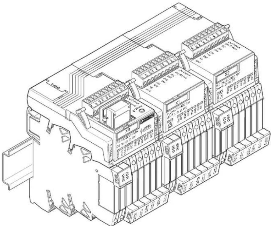
With eight fixed inputs and a further eight freely configurable I/O channels with electromechanical relays, solid-state relays or analog terminal blocks from the PLC-INTERFACE series, the system has a modular design and can process a maximum of 48 I/O signals with two PLC-V8C extension modules. Each of the freely configurable I/O channels can be configured as an input or output.
PLC logic is configured and programmed using the "LOGIC+" software. The software can be downloaded free of charge at phoenixcontact.net/products.
text_image
Technical diagram of an IBM PLC internal component with labeled ports and connectorsFigure 1-1 Entire system
1.4 What can PLC logic be used for?
PLC logic handles tasks in industrial, system, and installation technology as well as laboratory and training applications. Typical applications are listed in the table below.
Table 1-2 Possible applications
| Application Example | |
| Applications with time functions Switch-on/switch-off delay, weekly timer, pulse stretching, flashing relay | |
| Small machines Drives, pumps, valves, compressors, exhaust and filter systems, mixing machines, dosing machines | |
| Handling equipment Conveyors, lifting tables, freight elevators, silos, feeding systems | |
| Heating, ventilation, air conditioning | Fans, cooling, heating, air conditioning systems |
| Building automation Doors, barriers | shutters and blinds, sprinklers, lighting control systems |
| Other applications Signaling systems (e.g., construction sites), alarm systems | |
2 Hardware description
The PLC-V8C logic modules are inserted in the bridge shafts of eight PLC-INTERFACE terminal blocks mounted side by side on a DIN rail. All logic modules feature the following:
- Eight integrated digital inputs: two of which can be configured as analog inputs (0 V ... 10 V)
- Connection via connector with screw or Push-in connection technology
- Programming possible using the LOGIC+ software
The following PLC-V8C types are available:
PLC-V8C stand-alone modules
| Order No. Designation |
| 2905082 PLC-V8C/SC-24DC/SAM with screw connection |
| 2905136 PLC-V8C/PT-24DC/SAM with Push-in connection |
- Stand-alone logic module with 16 I/Os, cannot be extended
- Connection to PC via micro USB socket
- Integrated realtime clock
- Accommodates external IFS-CONFSTICK memory module
- A further eight channels can be configured with corresponding PLC-INTERFACE terminal blocks as digital inputs or outputs
PLC-V8C stand-alone modules 2
| Order No. Designation |
| 2907445 PLC-V8C/SC-24DC/SAM2 with screw connection |
| 2907443 PLC-V8C/PT-24DC/SAM2 with Push-in connection |
- Stand-alone logic module with 16 I/Os, cannot be extended
- Connection to PC via micro USB socket
- Integrated realtime clock
- Accommodates external IFS-CONFSTICK memory module
- A further eight channels can be configured with corresponding PLC-INTERFACE terminal blocks as digital or analog inputs or outputs
PLC-V8C basic modules
| Order No. Designation |
| 2903094 PLC-V8C/SC-24DC/BM with screw connection |
| 2905135 PLC-V8C/PT-24DC/BM with Push-in connection |
- Basic logic module with 16 I/Os, can be extended with a maximum of two extension modules (PLC-V8C.../EM) to 48 I/Os
- Connection to PC via micro USB socket
- Integrated realtime clock
- Accommodates external IFS-CONFSTICK memory module
- A further eight channels can be configured with corresponding PLC-INTERFACE terminal blocks as digital inputs or outputs
- Optional connection to Interface system gateways
PLC-V8C basic modules 2
| Order No. Designation |
| 2907447 PLC-V8C/SC-24DC/BM2 with screw connection |
| 2907446 PLC-V8C/PT-24DC/BM2 with Push-in connection |
- Basic logic module with 16 I/Os, can be extended with a maximum of two extension modules (PLC-V8C.../EM) to 48 I/Os
- Connection to PC via micro USB socket
- Integrated realtime clock
– Accommodates external IFS-CONFSTICK memory module - A further eight channels can be configured with corresponding PLC-INTERFACE terminal blocks as digital or analog inputs or outputs
- Optional connection to Interface system gateways
PLC-V8C extension modules
| Order No. Designation |
| 2903095 PLC-V8C/SC-24DC/EM with screw connection |
| 2905137 PLC-V8C/PT-24DC/EM with Push-in connection |
Extension logic module with 16 I/Os, for extending the basic module
The following PLC-INTERFACE terminal blocks can be connected to PLC-V8C.
Each channel can be configured as an input or output using the LOGIC+ software.
Table 2-1 Corresponding PLC-INTERFACE terminal blocks
| Type | Order designation | Order No. | Order designation | Order No. |
| Push-in connection Screw connection | ||||
| Relay output | ||||
| 1 changeover contact, 6 A, 250 V AC/DC | PLC-RPT-24DC/21 | 2900299 | PLC-RSC-24DC/21 | 2966171 |
| 1 changeover contact, 50 mA, 36 V DC, gold contact | PLC-RPT-24DC/21AU | 2900306 | PLC-RSC-24DC/21AU | 2966265 |
| 1 N/O contact, 6 A, 250 V AC/DC, actuator type | PLC-RPT-24DC/1/ACT | 2900312 | PLC-RSC-24DC/1/ACT | 2966210 |
| 1 N/O contact with switch, 6 A, 250 V AC/DC | PLC-RPT-24UC/1/S/H | 2900328 | PLC-RSC-24UC/1/S/H | 2982236 |
| Solid-state relay output | ||||
| 100 mA, 3 V DC ... 48 V DC | PLC-OPT-24DC/48DC/100 | 2900352 | PLC-OSC-24DC/48DC/100 | 2966728 |
| 3 A, 3 V DC ... 33 V DC | PLC-OPT-24DC/24DC/2 | 2900364 | PLC-OSC-24DC/24DC/2 | 2966634 |
| 750 mA, 24 V AC ... 253 V AC | PLC-OPT-24DC/230AC/1 | 2900369 | PLC-OSC-24DC/230AC/1 | 2967840 |
| 3 A, 3 V DC ... 33 V DC, actuator type | PLC-OPT-24DC/24DC/2/ACT | 2900376 | PLC-OSC-24DC/24DC/2/ACT | 2966676 |
| 750 mA, 24 V AC ... 253 V AC, actuator type | - | - | PLC-OSC-24DC/230AC/1/ACT | 2967947 |
| 1 A, 12 V DC ... 300 V DC | PLC-OPT-24DC/300DC/1 | 2900383 | PLC-OSC-24DC/300DC/1 | 2980678 |
| 10 A, 3 V DC ... 33 V DC | PLC-OPT-24DC/24 DC/10/R | 2900398 | PLC-OSC-24DC/24DC/10/R | 2982702 |
| 500 mA, 3 V DC ... 48 V DC, electronic changeover contact | PLC-OPT-24DC/48DC/500/W | 2900378 | PLC-OSC-24DC/48DC/500/W | 2980636 |
| TTL, 50 mA, 5 V DC | PLC-OPT-24DC/TTL | 2900363 | PLC-OSC-24DC/TTL | 2982728 |
| Analog input | ||||
| 0 V ... 10 V, 2 V ... 10 V,0 mA ... 20 mA, 4 mA ... 20 mA | PLC-APT-UI-IN | 2906917 PLC-ASC-UI-IN | 2906916 | |
| -50°C ... 200°C | PLC-APT-PT100-IN | 2906919 | PLC-ASC-PT100-IN | 2906918 |
| Relay input | ||||
| 24 V | DC | PLC-RPT-24DC/1AU/SEN | ||
| 120 V AC/DC | PLC-RPT-120UC/1AU/SEN | 2900314 | PLC-RSC-120UC/1AU/SEN | 2966320 |
| 230 V AC/DC | PLC-RPT-230UC/1AU/SEN | 2900315 | PLC-RSC-230UC/1AU/SEN | 2966333 |
| 5 V DC (basic terminal block without relay) | PLC-BSC- 5DC/ 1/SEN | 2980267 | - | - |
| Relay for 5 V DC basic terminal block | REL-MR-4,5DC/21AU | 2961370 | - | - |
| Solid-state relay input | ||||
| 24 V | DC | PLC-OPT-24DC/V8C/SEN | ||
| 120 V AC/DC | PLC-OPT-120UC/V8C/SEN | 2908174 | PLC-OSC-120UC/V8C/SEN | 2908175 |
| 230 V AC/DC | PLC-OPT-230UC/V8C/SEN | 2908176 | PLC-OSC-230UC/V8C/SEN | 2908177 |
| Analog output | ||||
| 0 V ... 10 V, 2 V ... 10 V,0 mA ... 20 mA, 4 mA ... 20 mA | PLC-APT-UI-OUT | 2906921 PLC-ASC-UI-OUT | 2906920 | |
| Dummy or reserve | ||||
| Basic terminal blocks output | PLC-BPT-24DC/21 | 2900445 | PLC-BSC-24DC/21 | 2966016 |
| Basic terminal blocks input | PLC-BPT-24DC/1/SEN | 2900262 | PLC-BSC-24DC/1/SEN | 2966061 |
2.1 Hardware configuration examples
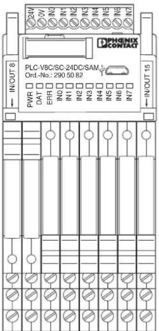
2.1.1 10 inputs, 6 outputs
| Inputs 24 V DC via eight integrated inputs and two PLC-INTER-FACE inputs via relays | |
| Outputs Via six PLC-INTERFACERelays, 1 N/O contact,250 V AC/6 A | |
| Connection technology Screw connection | |
| Required components 1x PL | LC-V8C/SC-24DC/SAM (Order No. 2905082)2x PLC-RSC-24DC/1AU/SEN (Order No. 2966317)6x PLC-RSC-24DC/1/ACT (Order No. 2966210) |
text_image
PHENIX CONTACT 24V IN/OUT 8 PLC-V8C/SC-24DC/SAM Ord.-No.: 290 50 82 PWR DAT ERR IN0 IN1 IN2 IN3 IN4 IN5 IN6 IN7 IN/OUT 15Figure 2-1 Configuration with 10 inputs, 6 outputs
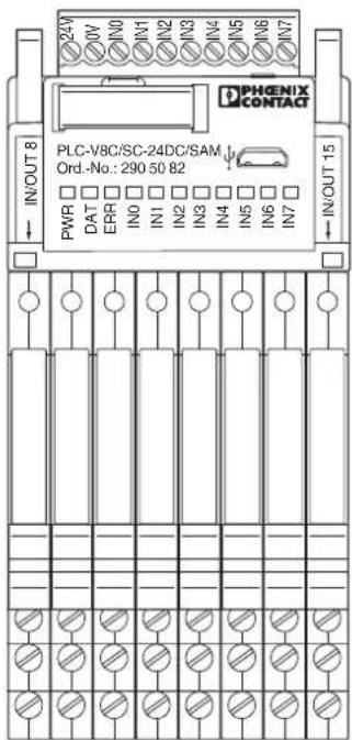
2.1.2 8 inputs, 8 outputs
| Inputs All 24 V DC inputs via | a eight integrated inputs |
| Outputs All outputs via PLC | -INTERFACE relays, 1 changeover contact, 250 V AC/6 A |
| Connection technology Screw connection | |
| Required components 1x P | LC-V8C/SC-24DC/SAM (Order No. 2905082)8x PLC-RSC-24DC/21 (Order No. 2966171) |
text_image
PHENIX CONTACT 24V DV IN0 IN1 IN2 IN3 IN4 IN5 IN6 IN7 IN/OUT 8 PLC-V8C/SC-24DC/SAM Ord.-No.: 290 50 82 PWR DAT ERR IN0 IN1 IN2 IN3 IN4 IN5 IN6 IN7 IN/OUT 15Figure 2-2 Configuration with 8 inputs, 8 outputs
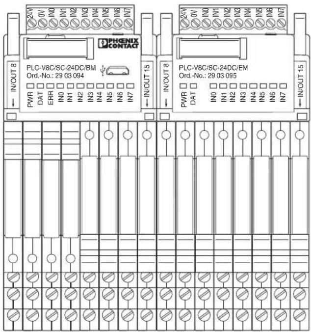
2.1.3 20 inputs, 12 outputs
| Inputs | 16 24 V DC inputs via 2x eight integrated inputs and four 230 V AC inputs via PLC-INTERFACE relays |
| Outputs 12 outputs via PLC | -INTERFACE solid-state relays,230 V AC/750 mA |
| Connection technology Screw connection | |
| Required components 1x PL | LC-V8C/SC-24DC/BM (Order No. 2903094)1x PLC-V8C/SC-24DC/EM (Order No. 2903095)4x PLC-RSC/230UC/1AU/SEN (Order No. 2966333)12x PLC-OSC-24DC/230AC/1/ACT (Order No. 2967947) |
text_image
PHENIX CONTACT IN/OUT 8 PWR DAT ERR IN0 IN1 IN2 IN3 IN4 IN5 IN6 IN7 IN/OUT 15 IN/OUT 8 PWR DAT ERR IN0 IN1 IN2 IN3 IN4 IN5 IN6 IN7 IN/OUT 15 PWR DAT ERR IN0 IN1 IN2 IN3 IN4 IN5 IN6 IN7Figure 2-3 Configuration with 20 inputs, 12 outputs
3 Installing PLC logic
The logic module is supplied together with a packing slip with installation instructions. Read the complete packing slip carefully before installing the logic module.

NOTE: Electrostatic discharge
The logic module contains components that can be damaged or destroyed by electrostatic discharge. When handling the logic module, observe the necessary safety precautions against electrostatic discharge (ESD) according to EN 61340-5-1 and IEC 61340-5-1.

NOTE: Risk of damage to equipment
To avoid possible damage to the logic module, unpack and pack the logic module in accordance with the ESD regulations.
3.1 Connection and operating elements
3.1.1 Stand-alone logic modules
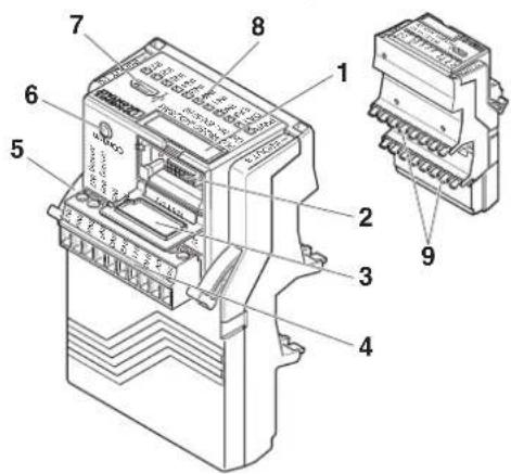
text_image
Technical diagram of an electronic device with numbered components and labeled parts in ChineseFigure 3-1 Connection and operating elements of stand-alone logic modules
- Equipment marking label
- Socket for memory module (Memory)
- Cover for memory module
- 10-pos. COMBICON connector
- Eject lever
- Confirmation button (Confirm)
- Micro USB socket
- Status LEDs
- Contacts for PLC-INTERFACE terminal blocks
3.1.2 Basic logic modules
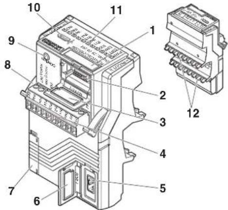
text_image
Technical diagram of an electrical switch with numbered components and labeled partsFigure 3-2 Connection and operating elements of basic logic modules
- Equipment marking label
- Socket for memory module (Memory)
- Cover for memory module
- 10-pos. COMBICON connector
- DIN rail connector connection
- DIN rail connector cover (T-BUS)
- Covering hood and socket contacts for the extension module
- Eject lever
- Confirmation button (Confirm)
- Micro USB socket
- Status LEDs
- Contacts for PLC-INTERFACE terminal blocks
3.1.3 Extension logic modules
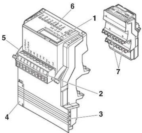
text_image
Technical diagram of an electrical connector with numbered parts and labeled terminalsFigure 3-3 Connection and operating elements of extension logic modules
- Equipment marking label
- 10-pos. COMBICON connector
- Knife contacts of extension modules
- Covering hood and socket contacts for the extension module
- Eject lever
- Status LEDs
- Contacts for PLC-INTERFACE terminal blocks
3.1.4 PLC-INTERFACE terminal blocks
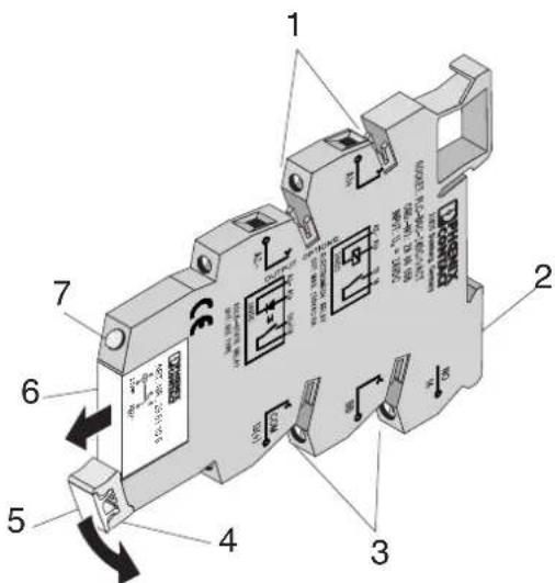
text_image
Technical diagram of an electrical fuse with numbered components and Chinese labels indicating parts 1 through 7.Figure 3-4 Connection and operating elements of PLC-INTERFACE terminal blocks
- Contacts to accommodate the logic module
- PLC-B... basic terminal block
- Contact for plug-in bridge system
- Snap-in lever for securing and ejecting the function electronics
- Optional ZB 6 equipment marking label
- Plug-in function electronics
- LED status indicator
3.2 Diagnostics and status indicators
The device is equipped with 11 LED status or diagnostics indicators, from which the operating state can be read.
Table 3-1 Diagnostic and status indicators
| Basic module Extension module | |||||||
| Green PWR LED | Green DAT LED | Red ERR LED | Yellow YE LED | Green PWR LED | Green DAT LED | Yellow YE LED | |
| Messages | |||||||
| Supply voltage not present | ● | ● | ● | ● | ● | ● | ● |
| Supply voltage OK, program running, no data traffic to the extension module | ○ | ● | ● | ● | ○ | ● | ● |
| Supply voltage OK, program running, data traffic to the extension module | ○ | ● | ● | ● | ○ | ○ | ● |
| Supply voltage OK, controller in stop mode | ☀️ | ● | ☀️ | ● | ○ | ● | ● |
| Supply voltage OK, connection to the extension module interrupted or error when saving retain variables | ☀️ | ● | ☀️ | ● | ● | ● | ● |
| Supply voltage OK, firmware update of basic module running | ○ | ☀️ | ● | ● | ○ | ● | ● |
| Supply voltage OK, firmware update of extension module running | ○ | ● | ● | ● | ○ | ☀️ | ● |
| Supply voltage OK, internal error at basic module | ○ | ● | ○ | ● | ○ | ● | ● |
| Supply voltage OK, external error | ○ | ● | ☀️ | ● | ○ | ● | ● |
| Supply voltage OK, short circuit at PLC outputs or overload error at basic or extension module | ○ | ● | ☀️ | ● | ○ | ● | ● |
| Digital inputs | |||||||
| Supply voltage OK, input at basic module, extension module controlled | ○ | ● | ● | ○ | ○ | ● | ○ |
| Supply voltage OK, input at basic module, extension module not controlled | ○ | ● | ● | ● | ○ | ● | ● |
| Memory stick | |||||||
| Supply voltage OK, copying new program to the memory stick | ○ | ☀️ | ● | ● | ○ | ● | ● |
| Supply voltage OK, finished copying | ○ | ● | ● | ● | ○ | ● | ● |
| Supply voltage OK, new program on the memory stick | ○ | ☀️ | ☀️ | ● | ○ | ● | ● |
| Supply voltage OK, error when handling the memory stick | ○ | ☀️ | ☀️ | ● | ○ | ● | ● |
| IFS gateway | |||||||
Table 3-1 Diagnostic and status indicators [...]
| Basic module Extension module | |||||||
| Green PWR LED | Green DAT LED | Red ERR LED | Yellow YE LED | Green PWR LED | Green DAT LED | Yellow YE LED | |
| Supply voltage OK, data traffic to the IFS gateway | (22HD) | (78C1) | (2573) | (X4V2) | (27HT) | (24TO) | ● |
| Supply voltage OK, data traffic to the IFS gateway, data traffic to the extension module | ○ | ○ | ● | ● | ○ | ○ | ● |
| Supply voltage OK, no data traffic to the IFS gate-way, no data traffic to the extension module | (52DK) | (2WH) | (K06A) | (ZGH3) | (7748) | (SHKD) | ● |
| Supply voltage OK, data traffic to the IFS gateway, connection to the extension module interrupted | (000Y) | (K30K) | (R3HK) | (23HW) | (747S) | (555X) | ● |
| Supply voltage OK, data traffic to the IFS gateway, controller in stop mode | (28CD) | (65TD) | (G42T) | (DCTY) | (C6ZZ) | (TXWE) | ● |
Table 3-2 Explanation of the symbols
| Symbol Description | |
| Level1 | LED is off |
| Level2 | LED is on |
| Level3 | LED is flashing |
| Level4 | LED is flashing quickly |
3.3 Circuit diagrams
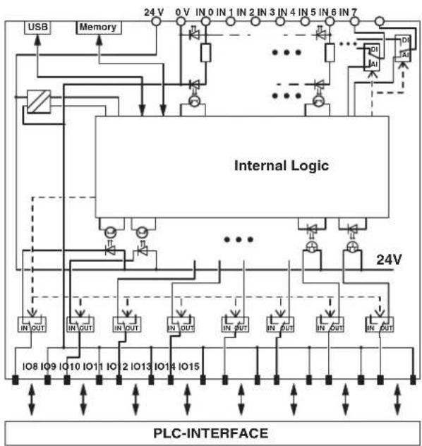
flowchart
graph TD
    A["USB"] --> B["Internal Logic"]
    C["Memory"] --> B
    B --> D["24V"]
    D --> E["0 V IN 0 IN 1 IN 2 IN 3 IN 4 IN 5 IN 6 IN 7"]
    B --> F["IN OUT"]
    B --> G["IN OUT"]
    B --> H["IN OUT"]
    B --> I["IN OUT"]
    B --> J["IN OUT"]
    B --> K["IN OUT"]
    B --> L["IN OUT"]
    B --> M["IN OUT"]
    B --> N["IN OUT"]
    B --> O["IN OUT"]
    B --> P["IN OUT"]
    B --> Q["IN OUT"]
    B --> R["IN OUT"]
    B --> S["IN OUT"]
    B --> T["IN OUT"]
    B --> U["IN OUT"]
    B --> V["IN OUT"]
    B --> W["IN OUT"]
    B --> X["IN OUT"]
    B --> Y["IN OUT"]
    B --> Z["IN OUT"]
    B --> AA["IN OUT"]
    B --> AB["IN OUT"]
    B --> AC["IN OUT"]
    B --> AD["IN OUT"]
    B --> AE["IN OUT"]
    B --> AF["IN OUT"]
    B --> AG["IN OUT"]
    B --> AH["IN OUT"]
    B --> AI["IN OUT"]
    B --> AJ["IN OUT"]
    B --> AK["IN OUT"]
    B --> AL["IN OUT"]
    B --> AM["IN OUT"]
    B --> AN["IN OUT"]
    B --> AO["IN OUT"]
    B --> AP["IN OUT"]
    B --> AQ["IN OUT"]
    B --> AR["IN OUT"]
    B --> AS["IN OUT"]
    B --> AT["IN OUT"]
    B --> AU["IN OUT"]
    B --> AV["IN OUT"]
    B --> AW["IN OUT"]
    B --> AX["IN OUT"]
    B --> AY["IN OUT"]
    B --> AZ["IN OUT"]
    B --> BA["IN OUT"]
    B --> BB["IN OUT"]
    B --> BC["IN OUT"]
    B --> BD["IN OUT"]
    B --> BE["IN OUT"]
    B --> BF["IN OUT"]
    B --> BG["IN OUT"]
    B --> BH["IN OUT"]
    B --> BI["IN OUT"]
    B --> BJ["IN OUT"]
    B --> BK["IN OUT"]
    B --> BL["IN OUT"]
    B --> BM["IN OUT"]
    B --> BN["IN OUT"]
    B --> BO["IN OUT"]
    B --> BP["IN OUT"]
    B --> BQ["IN OUT"]
    B --> BR["IN OUT"]
    B --> BS["IN OUT"]
    B --> BT["IN OUT"]
    B --> BU["IN OUT"]
    B --> BV["IN OUT"]
    B --> BW["IN OUT"]
    B --> BX["IN OUT"]
    B --> BY["IN OUT"]
    B --> BZ["IN OUT"]
    B --> CA["IN OUT"]
    B --> CB["IN OUT"]
    B --> CC["IN OUT"]
    B --> CD["IN OUT"]
    B --> CE["IN OUT"]
    B --> CF["IN OUT"]
    B --> CG["IN OUT"]
    B --> CH["IN OUT"]
    B --> CI["IN OUT"]
    B --> CJ["IN OUT"]
    B --> CK["IN OUT"]
Figure 3-5 Basic circuit diagram for PLC-V8C/.../SAM
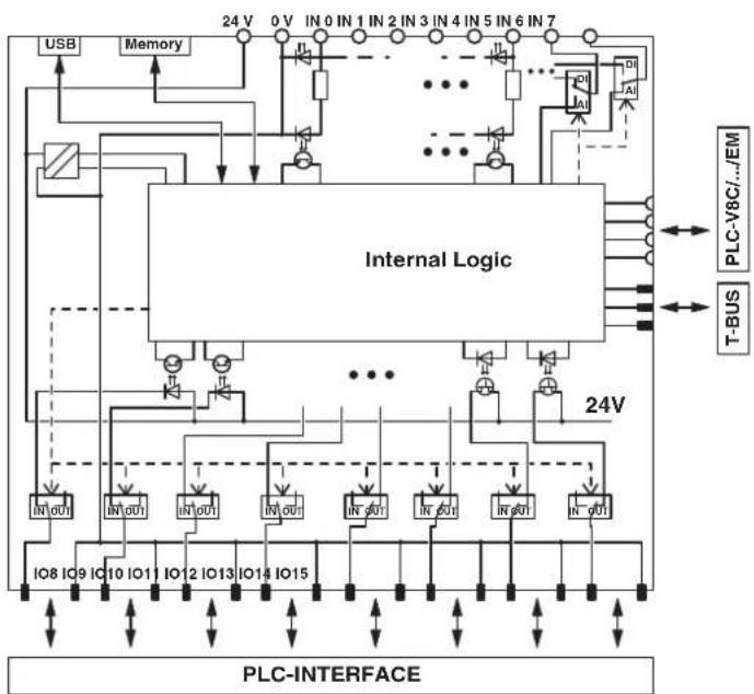
flowchart
graph TD
    A["USB"] --> B["Memory"]
    B --> C["Internal Logic"]
    C --> D["PLC-INTERFACE"]
    D --> E["T-BUS"]
    E --> F["PLC-V8C.../EM"]
    F --> G["24V"]
    G --> H["IO8 IO9 IO10 IO11 IO12 IO13 IO14 IO15"]
    H --> I["Pin 0 V IN 0 IN 1 IN 2 IN 3 IN 4 IN 5 IN 6 IN 7"]
    I --> J["Pin 0A"]
    J --> K["Pin 0B"]
    K --> L["Pin 0C"]
    L --> M["Pin 0D"]
    M --> N["Pin 0E"]
    N --> O["Pin 0F"]
    O --> P["Pin 0G"]
    P --> Q["Pin 0H"]
    Q --> R["Pin 0I"]
    R --> S["Pin 0J"]
    S --> T["Pin 0K"]
    T --> U["Pin 0L"]
    U --> V["Pin 0W"]
    V --> W["Pin 0X"]
    W --> X["Pin 0Y"]
    X --> Y["Pin 0Z"]
    Y --> Z["Pin 0A"]
    Z --> AA["Pin 0B"]
    AA --> AB["Pin 0C"]
    AB --> AC["Pin 0D"]
    AC --> AD["Pin 0E"]
    AD --> AE["Pin 0F"]
    AE --> AF["Pin 0G"]
    AF --> AG["Pin 0H"]
    AG --> AH["Pin 0I"]
    AH --> AI["Pin 0J"]
    AI --> AJ["Pin 0K"]
    AJ --> AK["Pin 0L"]
    AK --> AL["Pin 0M"]
    AL --> AM["Pin 0Y"]
    AM --> AN["Pin 0Z"]
    AN --> AO["Pin 0A"]
    AO --> AP["Pin 0B"]
    AP --> AQ["Pin 0C"]
    AQ --> AR["Pin 0D"]
    AR --> AS["Pin 0E"]
    AS --> AT["Pin 0W"]
    AT --> AU["Pin 0X"]
    AU --> AV["Pin 0Y"]
    AV --> AW["Pin 0Z"]
    AW --> AX["Pin 0A"]
    AX --> AY["Pin 0B"]
    AY --> AZ["Pin 0C"]
    AZ --> BA["Pin 0D"]
    BA --> BB["Pin 0E"]
    BB --> BC["Pin 0W"]
    BC --> BD["Pin 0X"]
Figure 3-6 Basic circuit diagram for PLC-V8C/.../BM
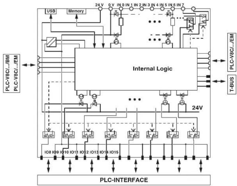
flowchart
graph TD
    subgraph PLC_INTERFACE
        A["USB"] --> B["Memory"]
        B --> C["Internal Logic"]
        C --> D["IO8 IO9 IO10 IO11 IO12 IO13 IO14 IO15"]
        D --> E["In OUT"]
        E --> F["IN OUT"]
        F --> G["In OUT"]
        G --> H["In OUT"]
        H --> I["In OUT"]
        I --> J["In OUT"]
        J --> K["In OUT"]
        K --> L["In OUT"]
        L --> M["In OUT"]
        M --> N["In OUT"]
        N --> O["In OUT"]
        O --> P["In OUT"]
        P --> Q["In OUT"]
        Q --> R["In OUT"]
        R --> S["In OUT"]
        S --> T["In OUT"]
        T --> U["In OUT"]
        U --> V["In OUT"]
        V --> W["In OUT"]
        W --> X["In OUT"]
        X --> Y["In OUT"]
        Y --> Z["In OUT"]
        Z --> AA["In OUT"]
        AA --> AB["In OUT"]
        AB --> AC["In OUT"]
        AC --> AD["In OUT"]
        AD --> AE["In OUT"]
        AE --> AF["In OUT"]
        AF --> AG["In OUT"]
        AG --> AH["In OUT"]
        AH --> AI["In OUT"]
        AI --> AJ["In OUT"]
        AJ --> AK["In OUT"]
        AK --> AL["In OUT"]
        AL --> AM["In OUT"]
        AM --> AN["In OUT"]
        AN --> AO["In OUT"]
        AO --> AP["In OUT"]
        AP --> AQ["In OUT"]
        AQ --> AR["In OUT"]
        AR --> AS["In OUT"]
        AS --> AT["In OUT"]
        AT --> AU["In OUT"]
        AU --> AV["In OUT"]
        AV --> AW["In OUT"]
        AW --> AX["In OUT"]
        AX --> AY["In OUT"]
        AY --> AZ["In OUT"]
        AZ --> BA["In OUT"]
        BA --> BB["In OUT"]
        BB --> BC["In OUT"]
        BC --> BD["In OUT"]
        BD --> BE["In OUT"]
        BE --> BF["In OUT"]
        BF --> BG["In OUT"]
        BG --> BH["In OUT"]
        BH --> BI["In OUT"]
        BI --> BJ["In OUT"]
        BJ --> BK["In OUT"]
        BK --> BL["In OUT"]
        BL --> BM["In OUT"]
        BM --> BN["In OUT"]
        BN --> BO["In OUT"]
        BO --> BP["In OUT"]
        BP --> BQ["In OUT"]
        BQ --> BR["In OUT"]
        BR --> BS["In OUT"]
        BS --> BT["In OUT"]
        BT --> BU["In OUT"]
        BU --> BV["In OUT"]
        BV --> BW["In OUT"]
        BW --> BX["In OUT"]
        BX --> BY["In OUT"]
        BY --> BZ["In OUT"]
        BZ --> CA["In OUT"]
        CA --> CB["In OUT"]
        CB --> CC["In OUT"]
        CC --> CD["In OUT"]
        CD --> CE["In OUT"]
        CE --> CF["In OUT"]
        CF --> CG["In OUT"]
        CG --> CH["In OUT"]
        CH --> CI["In OUT"]
        CI --> CJ["In OUT"]
        CJ --> CK["In OUT"]
        CK --> CL["In OUT"]
        CL --> CM["In OUT"]
        CM --> CN["In OUT"]
        CN --> CO["In OUT"]
        CO --> CP["In OUT"]
        CP --> CQ["In OUT"]
        CQ --> CR["In OUT"]
        CR --> CS["In OUT"]
        CS --> CT["In OUT"]
        CT --> CU["In OUT"]
        CU --> CV["In OUT"]
        CV --> CW["In OUT"]
        CW --> CX["In OUT"]
        CX --> CY["In OUT"]
        CY --> CZ["In OUT"]
        CZ --> DA["In OUT"]
        DA --> DB["In OUT"]
        DB --> DC["In OUT"]
        DC --> DD["In OUT"]
        DD --> DE["In OUT"]
        DE --> DF["In OUT"]
        DF --> DG["In OUT"]
        DG --> DH["In OUT"]
        DH --> DI["In OUT"]
        DI --> DJ["In OUT"]
        DJ --> DK["In OUT"]
        DK --> DL["T-BUS"]
    end
    subgraph PLC_INTERFACE
    A
    B
    C
    D
    E
    F
    G
    H
    I
    J
    K
    L
    M
    N
    O
    P
    Q
    R
    S
    T
    U
    V
    W
    X
    Y
    Z
    AA
    AB
    AC
    AD
    AE
    AF
    AG
    AH
    AI
    AJ
    AK
    AL
    AM
    AN
    AO
    AP
    AQ
    AR
    AS
    AT
    AU
    AV
    AW
    AX
    AY
    AZ
    BA
    BB
    BC
    BD
    BE
    BF
    BG
    BH
    BI
    BJ
    BK
    BL
    BM
    BN
    BO
    BP
    BPB
    BPCC
    BPCCB
    BPCCN
    BPCCNCC
    BPCCNCCN
    BPCCNCCNCC
    BPCCNCCNCCNCCNCCNCCNCCNCCNCCNCCNCCNCCNCCNCCNCCNCCNCCNCCNCCNCCNCCNCCNCCNCCNCCNCCNCCNCCNCCNCCNCCNCCNCCNCCNCCNCCNCCNCCNCCNCCNCCNCCNCCNCCNCCNCCNCCNCCNCCNCCNCCNCNCCNCCNCCNCCNCCNCCNCCNCCNCCNCCNCCNCCNCCNCCNCCNCCNCCNCCNCCNCCNCCNCCNCCNCCNCCNCCNCCNCCNCCNCCNCCNCCNCCNCCNCCNCCNCCNCCNCCNCCNCCNCCNCCNCCNCCNCCNCCNCCNCCNCCCNCNCNCNCNCNCNCNCNCNCNCNCNCNCNCNCNCNCNCNCNCNCNCNCNCNCNCNCNCNCNCNCNCNCNCNCNCNCNCNCNCNCNCNCNCNCNCNCNCNCNCNCNCNCNCNCNCNCNCNCNCNCNCNCNCNCNCNCNCNCNCNCNCNCNCNCNCNCNCNCNCNCNCNCNCNCNCNCNCNCNCNCNCNCNCNCNCNCNCNCNSCNCNSCNCNSCNCNSCNCNSCNCNSCNCNSCNCNSCNCNSCNCNSCNCNSCNCNSCNCNSCNCNSCNCNSCNCNSCNCNSCNCNSCNCNSCNCNSCNCNSCNCNSCNCNSCNCNSCNCNSCNCNSCNCNSCNCNSCNCNSCNCNSCNCNSCNCNSCNCNSCNCNSCNAAIAIAIAIAIAIAIAIAIAIAIAIAIAIAIAIAIAIAIAIAIAIAIAIAIAIAIAIAIAIAIAIAIAIAIAIAIAIAIAIAIAIAIAIAIAIAIAIAIAIAIAIAIAIAIAIAIAIAIAIAIAIAIAIAIAIAIAIAIAIAIAIAIAIAIAIAIAIAIAIAIAIAIAIAIAIAIAIAIAIAIAIAIAIAIAIAIAIAIAIAIACCAACCAACCAACCAACCAACCAACCAACCAACCAACCAACCAACCAACCAACCAACCAACCAACCAACCAACCAACCAACCAACCAACCAACCAACCAACCAACCAACCAACCAACCAACCAACCAACCAACCAACCAACCAACCAACCAACCAACCAACCAACCAACCAACCAACCAACCAACCAACCAACCAACCAACCAAAGAAAGAAAGAAAGAAAGAAAGAAAGAAAGAAAGAAAGAAAGAAAGAAAGAAAGAAAGAAAGAAAGAAAGAAAGAAAGAAAGAAAGAAAGAAAGAAAGAAAGAAAGAAAGAAAGAAAGAAAGAAAGAAAGAAAGAAAGAAAGAAAGAAAGAAAGAAAGAAAGAAAGAAAGAAAGAAAGAAAGAAAGAAAGAAAGAAAGAAAGAAGAAGAAGAAGAAGAAGAAGAAGAAGAAGAAGAAGAAGAAGAAGAAGAAGAAGAAGAAGAAGAAGAAGAAGAAGAAGAAGAAGAAGAAGAAGAAGAAGAAGAAGAAGAAGAAGAAGAAGAAGAAGAAGAAGAAGAAGAAGAUGAACGATGATGATGATGATGATGATGATGATGATGATGATGATGATGATGATGATGATGATGATGATGATGATGATGATGATGATGATGATGATGATGATGATGATGATGATGATGATGATGATGATGATGATGATGATGATGATGATGATGATGATTGGTGGTGGTGGTGGTGGTGGTGGTGGTGGTGGTGGTGGTGGTGGTGGTGGTGGTGGTGGTGGTGGTGGTGGTGGTGGTGGTGGTGGTGGTGGTGGTGGTGGTGGTGGTGGTGGTGGTGGTGGTGGTGGTGGTGGTGGTGGTGGTGGTGGTGGTTTGTTTGTTTGTTTGTTTGTTTGTTTGTTTGTTTGTTTGTTTGTTTGTTTGTTTGTTTGTTTGTTTGTTTGTTTGTTTGTTTGTTTGTTTGTTTGTTTGTTTGTTTGTTTGTTTGTTTGTTTGTTTGTTTGTTTGTTTGTTTGTTTGTTTGTTTGTTTGTTTGTTTGTTTGTTTGTTTGTTTGTTTGTTTGTTTGTTTGTTGTTTGTTTGTTTGTTTGTTTGTTTGTTTGTTTGTTTGTTTGTTTGTTTGTTTGTTTGTTTGTTTGTTTGTTTGTTTGTTTGTTTGTTTGTTTGTTTGTTTGTTTGTTTGTTTGTTTGTTTGTTTGTTTGTTTGTTTGTTTGTTTGTTTGTTTGTTTGTTTGTTTGTTTGTTTGTTTGTTTGTTTGTTTGTTTGTTTGTTTCCTTCCTTCCTTCCTTCCTTCCTTCCTTCCTTCCTTCCTTCCTTCCTTCCTTCCTTCCTTCCTTCCTTCCTTCCTTCCTTCCTTCCTTCCTTCCTTCCTTCCTTCCTTCCTTCCTTCCTTCCTTCCTTCCTTCCTTCCTTCCTTCCTTCCTTCCTTCCTTCCTTCCTTCCTTCCTTCCTTCCTTCCTTCCTTCCTTCCTTCACTTCCTTCCTTCCTTCCTTCCTTCCTTCCTTCCTTCCTTCCTTCCTTCCTTCCTTCCTTCCTTCCTTCCTTCCTTCCTTCCTTCCTTCCTTCCTTCCTTCCTTCCTTCCTTCCTTCCTTCCTTCCTTCCTTCCTTCCTTCCTTCCTTCCTTCCTTCCTTCCTTCCTTCCTTCCTTCCTTCCTTCCTTCCTTCCTTCCTTC<nl>
Figure 3-7 Basic circuit diagram for PLC-V8C/.../EM
3.4 Mounting and removing PLC logic
3.4.1 Safety notes
Position an end bracket at the start and end of a PLC logic structure (recommendation: CLIPFIX 35-5, Order No. 3022276). If subject to vibration, the DIN rail needs to be fixed at intervals of 10 cm.
3.4.2 Mounting stand-alone and basic modules
Proceed as follows to mount PLC logic:
- Snap the eight corresponding PLC-INTERFACE terminal blocks (see Table 2-1 on page 15) side by side onto the DIN rail.
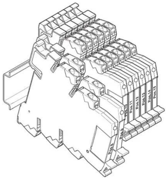
Figure 3-8 Snapping the PLC-INTERFACE terminal blocks onto the DIN rail
-
Insert the logic module (stand-alone or basic module) into the corresponding contacts of the eight PLC-INTERFACE terminal blocks. In general, the logic module is inserted in the contact locators of the PLC-INTERFACE terminal blocks, which also have a foot lever for the terminal block located on the side (item 1 Figure 3-4 on page 23).
-
Make sure that the logic module is flush with the PLC-INTERFACE terminal blocks. The logic module can then be fixed in place correctly.
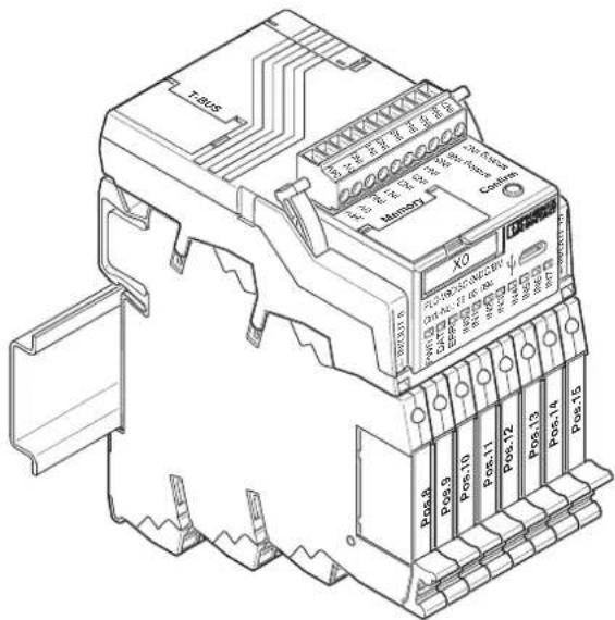
Figure 3-9 Logic module is fixed in place
3.4.3 Mounting extension modules
If you require more I/O signals than are supported with the PLC-V8C...BM basic module, connect a maximum of two PLC-V8C...EM extension modules to the basic module.
- Remove the covering hood (7) from the basic module (see Figure 3-2 on page 21).
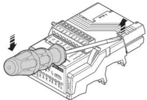
text_image
Technical diagram of an electrical connector with labeled ports and internal components, showing a cable or terminal assembly.-
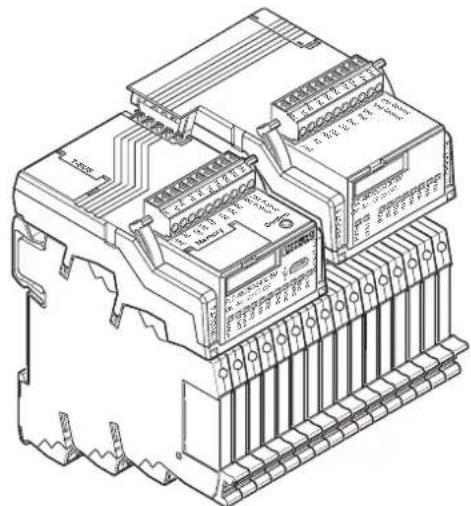
Connect a further eight PLC-INTERFACE terminal blocks to the last PLC-INTERFACE terminal block of the basic module.
-
Insert the extension module in the bridge shafts of the PLC-INTERFACE terminal blocks. Contact is automatically established with the basic module via the plug-in connection (7) and (13) (see Figure 3-2 on page 21).
natural_image
Technical line drawing of an electronic component with multiple ports and connectors (no text or symbols)- Proceed in the same way to attach a second extension module. To do this, remove the covering hood (7) on the first extension module (see Figure 3-3 on page 22).
3.4.4 Removal
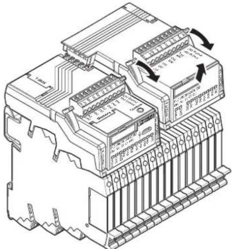
The logic module is disconnected from the PLC-INTERFACE terminal blocks by simultaneously actuating both eject levers. Proceed as follows:
First remove the last extension module, followed by the first extension module and then the basic module.
natural_image
Technical line drawing of an electronic component with multiple ports and connectors (no text or symbols)Figure 3-10 Actuating the eject levers to remove the logic modules
4 Connecting and wiring PLC logic
4.1 Power supply
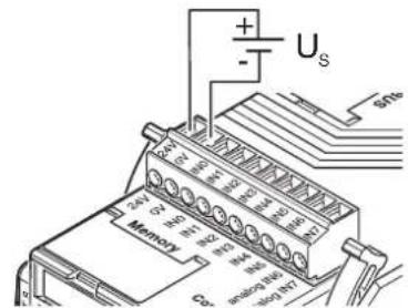
The logic modules are supplied with voltage via the 10-pos. COMBICON connector. Optional extension modules must be supplied separately.
text_image
+ - U_S S16 240 300 350 400 450 500 550 600 650 700 750 800 850 900 950 1000 1050 1100 1150 1200 1250 1300 1350 1400 1450 1500 1550 1600 1650 1700 1750 1800 1850 1900 1950 2000 2050 2100 2150 2200 2250 2300 2350 2400Figure 4-1 Power supply
Table 4-1 Connection data for the 10-pos. COMBICON connector
| Connector type Screw connection | |
| Conductor cross section (solid/stranded) 0.1 | 4 - 1.5 mm^2 /0.14 - 1.5 mm^2 /28 - 16 AWG |
| Stripping length 7 mm | |
| Tightening torque 0.22 - 0.25 Nm | |
| Connector that can be ordered as replace-ment part | MC 1,5/10-ST-3,5 (unprinted)(Order No. 1840447) |
| Connector type Push-in connection | |
| Conductor cross section (solid/stranded) 0.1 | 4 - 1.5 mm^2 /0.14 - 1.5 mm^2 /28 - 16 AWG |
| Stripping length 9 mm | |
| Connector that can be ordered as replace-ment part | FK-MCP 1,5/10-ST-3,5 (unprinted)(Order No. 1939989) |
4.2 Inputs and outputs
4.2.1 Integrated inputs
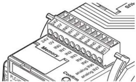
Like the power supply, the eight integrated inputs (IN0 to IN7) are connected via the 10-pos. COMBICON connector (for connection data, see Table 4-1 on page 33).
text_image
24V 0V IN0 INT1 IN2 IN3 IN4 IN5 IN6 IN7 Memory Confirm PLC-04 SN16Figure 4-2 Integrated inputs
Table 4-2 Properties of the integrated inputs
| Status IN0 to IN5 IN6, IN7 | ||
| Off | < 5 V D C | < 5 V D C |
| Input current | < 0.9 mA | < 1 mA |
| On | >11 V D C | >11 V D C |
| Input current | >2.2 mA | >2.3 mA |
When the status changes from "Off" to "On", the voltage must be >11 V DC for at least one program cycle so that the logic module detects the new status. The same applies when the status changes from "On" to "Off". In this case the voltage must be <5 V DC for at least one program cycle so that the new status is detected.
For information on the cycle time, see "Cycle time" on page 82.
Inputs IN6 and IN7 can be used as digital inputs or as analog inputs (0 V DC ... 10 V DC voltage inputs). Configuration is carried out in the LOGIC+ software.
4.2.1.1 Connecting integrated inputs
text_image
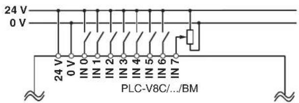
24 V 0 V 24 V 0 V IN 0 IN 1 IN 2 IN 3 IN 4 IN 5 IN 6 IN 7 PLC-V8C/.../BMFigure 4-3 Connecting integrated inputs
The integrated inputs are non-isolated, i.e., they have the same ground as the supply voltage. For floating entries, the inputs are available via PLC-INTERFACE terminal blocks (POS.8 to POS.15).
4.2.1.2 Designation of the inputs
Table 4-3 Stand-alone logic module and basic logic module (station 0)
| Connector designation Designation in LOGIC+ | |
| IN0 DI_0_0 | |
| IN1 DI_0_1 | |
| IN2 DI_0_2 | |
| IN3 DI_0_3 | |
| IN4 DI_0_4 | |
| IN5 DI_0_5 | |
| IN6 DI_0_6 (digital), AI_0_6 (analog) | |
| IN7 DI_0_7 (digital), AI_0_7 (analog) | |
Table 4-4 First extension logic module (station 1)
| Connector designation Designation in LOGIC+ | |
| IN0 DI_1_0 | |
| IN1 DI_1_1 | |
| IN2 DI_1_2 | |
| IN3 DI_1_3 | |
| IN4 DI_1_4 | |
| IN5 DI_1_5 | |
| IN6 DI_1_6 (digital), AI_1_6 (analog) | |
| IN7 DI_1_7 (digital), AI_1_7 (analog) | |
Table 4-5 Second extension logic module (station 2)
| Connector designation Designation in LOGIC+ | |
| IN0 DI_2_0 | |
| IN1 DI_2_1 | |
| IN2 DI_2_2 | |
| IN3 DI_2_3 | |
| IN4 DI_2_4 | |
| IN5 DI_2_5 | |
| IN6 DI_2_6 (digital), AI_2_6 (analog) | |
| IN7 DI_2_7 (digital), AI_2_7 (analog) | |
4.2.2 Inputs and outputs via PLC-INTERFACE terminal blocks
The PLC-V8C logic modules are inserted in the bridge shafts of eight PLC-INTERFACE terminal blocks mounted side by side on a DIN rail. These eight PLC-INTERFACE terminal blocks form the inputs or outputs at positions Pos.8 to Pos.15. Analog inputs or outputs are available for PLC-V8C...BM2 and PLC-V8C...SAM2. The relevant position is set as an input or output in the LOGIC+ software (see "Hardware configuration" on page 72). Once this is specified, the corresponding PLC-INTERFACE terminal block can be used at the relevant position. In order to ensure sufficient mechanical stability, use basic terminal blocks for channels that are not required. For a list of corresponding PLC-INTERFACE terminal blocks, refer to Table 2-1 on page 15.

NOTE: Risk of short circuit
When wiring a mixture of inputs/outputs via PLC-INTERFACE in the field, observe the different potentials on the same connection levels.
Terminal points BB, 13, and A2 have different potentials with output and input relays (see Figure 4-8 on page 41 and Figure 4-13 on page 45). Make sure that a short circuit does not occur when using FBST plug-in bridges. The following 2-pos. plug-in bridges are recommended for bridging the same potential and for the clear delimitation of different potentials.
Table 4-6 Recommended plug-in bridges
| Color Order designation Order number | |
| Red FBST 6-PLC RD 2966236 | |
| Blue FBST 6-PLC BU 2966182 | |
| Gray FBST 6-PLC GY 2966825 |
4.2.2.1 Designation of inputs and outputs via PLC-INTERFACE terminal blocks
In the LOGIC+ software, digital inputs have the designation DI_X_X and digital outputs have the designation DQ_X_X.
In the LOGIC+ software, analog inputs have the designation AI_X_X and analog outputs have the designation AQ_X_X.
Table 4-7 Stand-alone logic module and basic logic module (station 0)
Table 4-8 First extension logic module (station 1)
Table 4-9 Second extension logic module (station 2)
4.2.2.2 Connection technology of PLC-INTERFACE terminal blocks
text_image
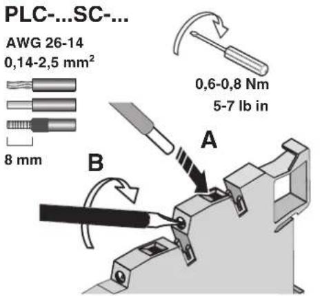
PLC-...SC-... AWG 26-14 0,14-2,5 mm² 8 mm 0,6-0,8 Nm 5-7 lb in A BFigure 4-4 PLC modules with screw connection
PLC-...PT-...
text_image
AWG 26-14 0,14-2,5 mm² 10 mm A BFigure 4-5 PLC modules with Push-in connection
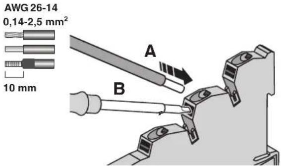
Insert solid or stranded conductors with ferrules and a cross section ≥ 0.34 mm^2 directly in the clamping space (A). Reliable contact can be made with stranded conductors without ferrules by opening the spring beforehand using the pushbutton (B). Press the pushbutton (B) also to release the conductor.
4.2.2.3 Digital inputs via PLC-INTERFACE terminal blocks
If you have defined a slot as a digital input, you can use PLC-INTERFACE terminal blocks from the sensor series with electromechanical or solid-state relays. You can connect different input voltages. The digital inputs via the PLC-INTERFACE terminal blocks are therefore electrically isolated between field and logic level as well as between the individual channels.

Data sheets for the PLC-INTERFACE terminal blocks can be found at: phoenixcontact.net/products

NOTE:
Voltages > 250 V are not permitted between the same terminal points on adjacent modules (L1, L2, L3).
Supply currents ≤ 6 A directly to the corresponding terminal points. For higher currents, use the PLC-ESK GY feed-in terminal (Order No. 2966508).
Wiring of digital inputs via PLC-INTERFACE terminal blocks
flowchart
graph TD
    A["PLC-V8C..."] --> B["2966333 PLC-RSC-230C/1AU/SEN"]
    A --> C["2904690 PLC-OSC-24DC/48DC/100/V8C/SEN"]
    B --> D["BB A2A1"]
    C --> E["BB A2A1"]
    D --> F["Switch"]
    E --> G["Switch"]
    F --> H["Ground"]
    G --> I["Ground"]
    J["230 V"] --> K["N"]
    L["24 V"] --> M["0 V"]
    N["14 13"] --> O["Diode"]
    P["14 13"] --> Q["Diode"]
    R["14 13"] --> S["Diode"]
    T["14 13"] --> U["Diode"]
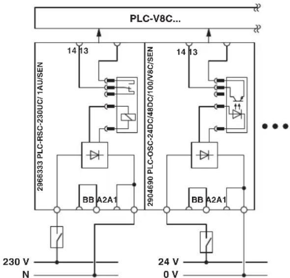
Figure 4-6 Wiring of digital inputs via PLC-INTERFACE terminal blocks
Basic circuit diagram with the example of an input terminal block with relay, 230 V AC (PLC-RSC-230UC/1 AU/SEN, Order No. 2966333) and an input terminal block with solid-state relay, 24 V DC (PLC-OSC-24DC/48DC/100/V8C/SEN, Order No. 2904690).
Pin assignment of digital inputs via PLC-INTERFACE terminal blocks
text_image
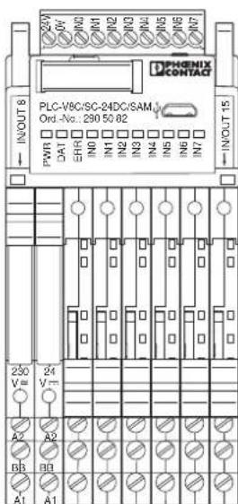
DPHENIX CONTACT PLC-V5C/SC-24DC/SAM Ord.-No.: 230 50 82 PWR DAT ERRD IN1 IN2 IN3 IN4 IN5 IN6 IN7 INOUT 15 250 V= 24 V= A2 A2 BB BB A1 A1Figure 4-7 Pin assignment of digital inputs via PLC-INTERFACE terminal blocks
Connections of an input terminal block with relay, 230 V AC (PLC-RSC-230UC/1 AU/SEN, Order No. 2966333) and an input terminal block with solid-state relay, 24 V DC (PLC-OSC-24DC/48DC/100/V8C/SEN, Order No. 2904690).

Corresponding PLC-INTERFACE terminal blocks for digital inputs can be found in Table 2-1 on page 15.
Optional convenient connection when wiring digital inputs via PLC-INTERFACE terminal blocks
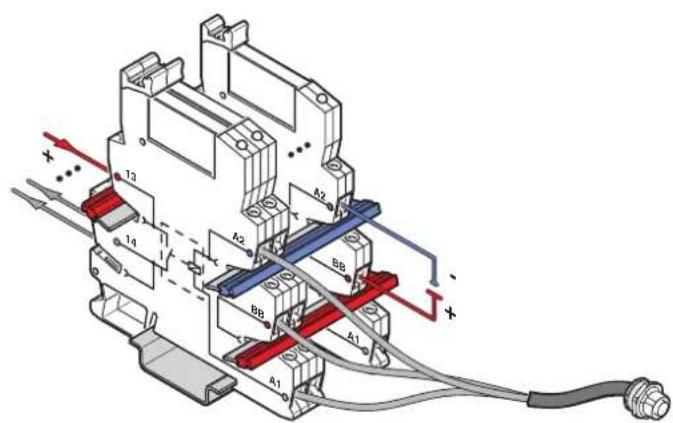
The PLC-...SEN sensor series for input signals offers additional connection convenience. A separate external terminal block is not required for the respective switch supply. The switch supply can be connected to terminal point "BB".
text_image
Technical diagram of an electrical contactor with labeled components and wiring connectionsFigure 4-8 Convenient connection of the sensor series
4.2.2.4 Analog inputs via PLC-INTERFACE terminal blocks (PLC-V8C...BM2 and PLC-V8C...SAM2 only)
If you have defined a slot as an analog input, you can use PLC-ASC-UI-IN (Order No. 2906916), PLC-ASC-UI-IN (Order No. 2906917), PLC-ASC-PT100-IN (Order No. 2906918) or PLC-APT-PT100-IN (Order No. 2906919) PLC-INTERFACE terminal blocks.

Data sheets for the PLC-INTERFACE terminal blocks can be found at: phoenixcontact.net/products
Wiring of analog inputs via PLC-INTERFACE terminal blocks

flowchart
graph TD
    A["Logic module PLC-V8C..."] --> B["μC"]
    B --> C["Data+"]
    C --> D["OUT"]
    C --> E["IN"]
    D --> F["4-wire"]
    E --> F
    F --> G["U2"]
    style A fill:#f9f,stroke:#333
    style G fill:#ccf,stroke:#333
Figure 4-9 Wiring of analog input modules
flowchart
graph TD
    A["Logic module PLC-V8C..."] --> B["μC"]
    B --> C["Data-"]
    B --> D["Data+"]
    C --> E["24V"]
    D --> F["GND"]
    E --> G["Sensor / Field"]
    F --> G
    H["OUT"] --> I["μC"]
    J["IN"] --> K["24V"]
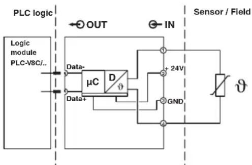
Figure 4-10 Wiring of Pt 100/Pt 1000 temperature transducers

Corresponding PLC-INTERFACE terminal blocks for analog inputs can be found in Table 2-1 on page 15.
4.2.2.5 Digital outputs via PLC-INTERFACE
When using PLC-INTERFACE terminal blocks, observe the requirements regarding noise emission for electrical and electronic equipment on the contact side.
In the event of a higher load and inductive load component, implement a contact protection circuit (e.g. freewheeling diode, varistor, RC element) at the load. This prevents interference voltages being coupled to other system parts. The relays also contribute to a longer electrical service life.

Data sheets for the PLC-INTERFACE terminal blocks can be found at: phoenixcontact.net/products

NOTE:
Voltages > 250 V are not permitted between the same terminal points on adjacent modules (L1, L2, L3).
Supply currents ≤ 6 A directly to the corresponding terminal points. For higher currents, use the PLC-ESK GY feed-in terminal (Order No. 2966508).
If you have defined a slot as a digital output, you can choose corresponding PLC-INTERFACE terminal blocks with electromechanical or solid-state relays.
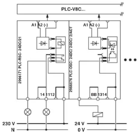
Wiring of digital outputs via PLC-INTERFACE terminal blocks
flowchart
graph TD
    A["PLC-V8C..."] --> B["A1 A2 (-)"]
    B --> C["296671 PLC-RSC-24DC/21"]
    B --> D["296676 PLC-OSC-24DC/2/ACT"]
    E["PLC-RSC-24DC/21"] --> F["14 112"]
    E --> G["BB 1314"]
    H["PLC-OSC-24DC/2/ACT"] --> I["14 112"]
    H --> J["BB 1314"]
    K["PLC-OSC-24DC/2/ACT"] --> L["14 112"]
    K --> M["BB 1314"]
    N["PLC-OSC-24DC/2/ACT"] --> O["14 112"]
    N --> P["BB 1314"]
    Q["PLC-OSC-24DC/2/ACT"] --> R["14 112"]
    Q --> S["BB 1314"]
    T["PLC-OSC-24DC/2/ACT"] --> U["14 112"]
    T --> V["BB 1314"]
    W["PLC-OSC-24DC/2/ACT"] --> X["14 112"]
    W --> Y["BB 1314"]
    Z["PLC-V8C..."] --> AA["..."]
    AB["230 V N"] --> AC["×"]
    AD["24 V 0 V"] --> AE["×"]
Figure 4-11 Wiring of digital outputs via PLC-INTERFACE terminal blocks
Basic circuit diagram with the example of an output terminal block with relay, 1 changeover contact (PLC-RSC-24DC/21, Order No. 2966171) and an output terminal block with solid-state relay, 24 V DC voltage output, and convenient actuator connection (PLC-OSC-24DC/24DC/2/ACT, Order No. 2966676).
Pin assignment of digital outputs via PLC-INTERFACE terminal blocks

text_image
PHOENIX CONTACT PLC-V8C/SC-24DC/SAM Ord.-No.: 230 50 62 PWR DAT ERR IN0 IN1 IN2 IN3 IN4 IN5 IN6 IN7 INOUT 15 Vmm 24 24 Vmm 11 13 14 BB 12 14Figure 4-12 Pin assignment of digital outputs via PLC-INTERFACE terminal blocks
Connections of an output terminal block with relay, 1 changeover contact (PLC-RSC-24DC/21, Order No. 2966171) and an output terminal block with solid-state relay, 24 V DC voltage output, and convenient actuator connection (PLC-OSC-24DC/24DC/2/ACT, Order No. 2966676).

Corresponding PLC-INTERFACE terminal blocks for digital outputs can be found in Table 2-1 on page 15.
Optional convenient connection when wiring digital outputs via PLC-INTERFACE terminal blocks
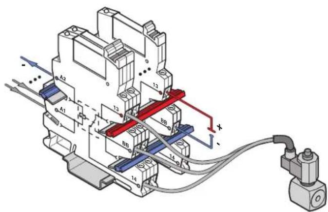
The PLC-...ACT actuator series for output signals offers additional connection convenience. A separate external output terminal block is not required for the load return line. The load return line can be connected to terminal point "BB".
text_image
Technical diagram of an electrical circuit with labeled components and wiring connectionsFigure 4-13 Convenient connection of the actuator series
4.2.2.6 Analog outputs via PLC-INTERFACE terminal blocks (PLC-V8C...BM2 and PLC-V8C...SAM2 only)
If you have defined a slot as an analog output, you can use PLC-ASC-UI-OUT (Order No. 2906920) or PLC-ASC-UI-OUT (Order No. 2906921) PLC-INTERFACE terminal blocks.

Data sheets for the PLC-INTERFACE terminal blocks can be found at: phoenixcontact.net/products
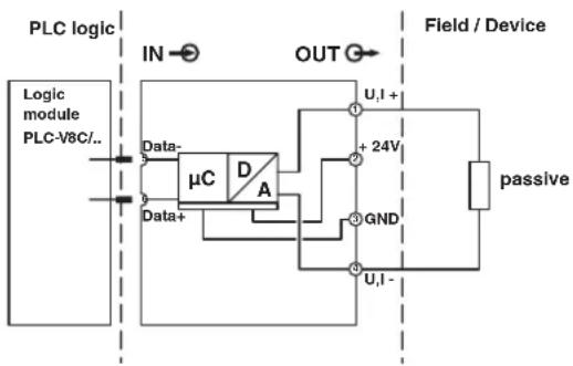
Wiring of analog outputs via PLC-INTERFACE terminal blocks
flowchart
graph TD
    A["Logic module PLC-V8C/.."] --> B["μC"]
    B --> C["Data+"]
    C --> D["GND"]
    D --> E["Field / Device"]
    E --> F["passive"]
    B --> G["IN"]
    G --> H["OUT"]
    H --> I["U,I+"]
    I --> J["+24V"]
    J --> K["GND"]
    K --> L["U,I-"]
Figure 4-14 Wiring of analog outputs via PLC-INTERFACE terminal blocks

Corresponding PLC-INTERFACE terminal blocks for analog outputs can be found in Table 2-1 on page 15.
4.3 Micro USB connection
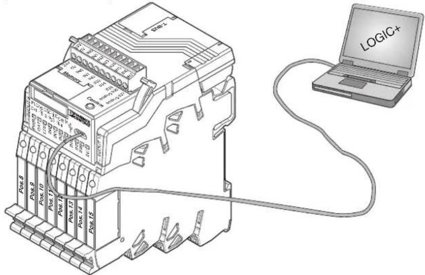
The micro USB connection can be used for communication between a PC and PLC logic. A standard micro USB A to USB B connecting cable, e.g., CAB-USB A/MICRO USB B/2,0M (Order No. 2701626), is required for the connection between PLC logic and a PC.
text_image
LOGIC+ Memory Pos 8 Pos 9 Pos 10 Pos 11 Pos 12 Pos 13 Pos 14 Pos 15 Pos 16 Pos 17 Pos 18 Pos 19 Pos 20 Pos 21 Pos 22 Pos 23 Pos 24 Pos 25 Pos 26 Pos 27 Pos 28 Pos 29 Pos 30 Pos 31 Pos 32 Pos 33 Pos 34 Pos 35 Pos 36 Pos 37 Pos 38 Pos 39 Pos 40 Pos 41 Pos 42 Pos 43 Pos 44 Pos 45 Pos 46 Pos 47 Pos 48 Pos 49 Pos 50 Pos 51 Pos 52 Pos 53 Pos 54 Pos 55 Pos 56 Pos 57 Pos 58 Pos 59 Pos 60 Pos 61 Pos 62 Pos 63 Pos 64 Pos 65 Pos 66 Pos 67 Pos 68 Pos 69 Pos 70 Pos 71 Pos 72 Pos 73 Pos 74 Pos 75 Pos 76 Pos 77 Pos 78 Pos 79 Pos 80Figure 4-15 PLC logic and PC connection
5 Startup
5.1 LOGIC+ software installation
The required LOGIC+ software can be downloaded free of charge at phoenixcontact.net/products. After downloading, follow the installation instructions to the end.
5.2 Device driver installation
Download the driver at phoenixcontact.net/products. If you have purchased STARTER-KIT1, you will also find the driver on the USB card supplied.
Start the driver setup file.

Administrator rights may be required to install the drivers.
5.3 Connection to the PC
If PLC logic is mounted as described in Section 3 on page 19, supply each of the logic modules with power. The PWR LED now lights up on every logic module.
Connect PLC logic to the PC (see Section 4.3 on page 47).
When the software is started, it automatically detects the PLC-V8C logic module as soon as the USB connection is established.
If the driver has been correctly identified, "Phoenix CDC ECM Network Adapter" appears under "Network adapters" in the Windows Device Manager.

The Ethernet network adapter is emulated via USB. This connection may be blocked by the firewall you are using. If so, contact your system administrator.
5.4 Configuration via web server
You can access the web server in a web browser by calling page http://v8c_usb.

Internet Explorer 10 or Mozilla Firefox 10 is required as a minimum in order to use the full scope of functions of the web server.
5.4.1 Monitoring, Diagnostics
5.4.1.1 Overview
Important device and project information is displayed on the overview page.
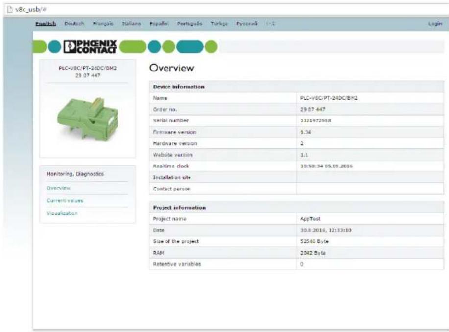
text_image
v8c.usb/# English Deutach Français Italiano Español Português Türke Pycocenã PHCENIX CONTACT PLC-V8C/PT-24DC/BM2 29.07.447 Overview Device information Name PLC-V8C/PT-24DC/BM2 Order no. 29.07.447 Serial number 1121972558 Firmware version 1.34 Hardware version 2 Website version 1.1 Realtime clock 10:58:34 09.09.2016 Installation site Contact person Project information Project name AppTest Date 30.8.2016, 12:13:10 Size of the project 52540 Byte RAM 2042 Byte Retentive variables 0© 2016 PHOENIX CONTACT Legal Notes
Figure 5-1 Overview
5.4.1.2 Current values
Current values and states of the hardware are displayed on this page, such as input and output states and error messages.
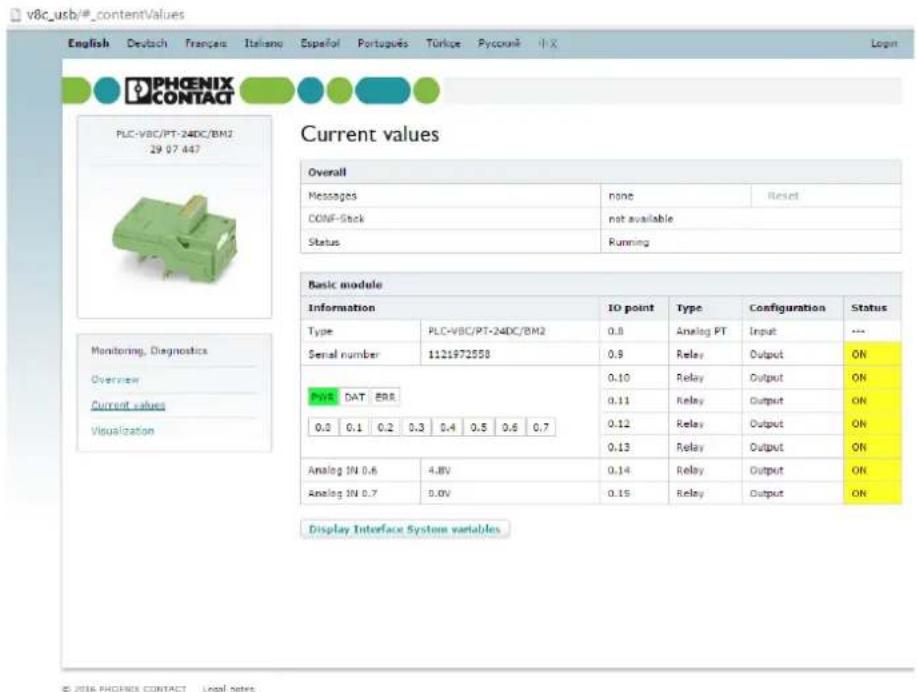
text_image
v8c_usb/#_contentValues English Deutsch Français Italiano Español Português Türkçe Pycocunié iX PHOENIX CONTACT PLC-VBC/PT-24DC/BM2 29.07.447 Current values Overall Messages none Reset CONF-Stck not available Status Running Basic module Information IO point Type Configuration Status Type PLC-VBC/PT-24DC/BM2 0.8 Analog PT Input --- Serial number 1121972558 0.9 Relay Output ON PYR DAT ERR 0.10 Relay Output ON 0.3 0.1 0.2 0.3 0.4 0.5 0.6 0.7 0.11 Relay Output ON Analog IN 0.6 4.8V 0.12 Relay Output ON Analog IN 0.7 0.0V 0.13 Relay Output ON Display Interface System variables Monitoring, Diagnostics Overview Current values VisualizationFigure 5-2 Current values
5.4.1.3 Visualization
The configured visualization pages are displayed on this page. Variables and various states can be displayed clearly here. The visualization is divided into several pages.
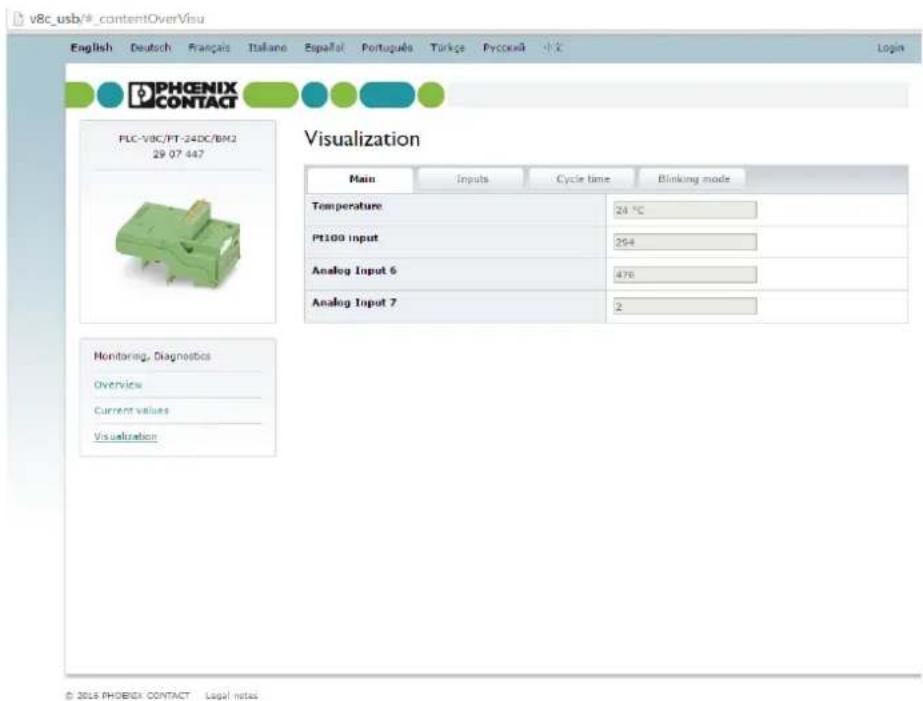
text_image
v8c_usb/#_contentOverVisu English Deutsch Français Italiane Español Portugues Törkçe Pycokéi PHOENIX CONTACT FLC-V8C/PT-24DC/BM2 29 07 447 Visualization Main Inputs Cycle time Blinking mode Temperature 24 °C Pt100 Input 264 Analog Input 6 476 Analog Input 7 2 Monitoring, Diagnostics Overview Current values Visualization © 2015 PHOENIX CONTACT Legal notesFigure 5-3 Visualization
5.4.2 Login
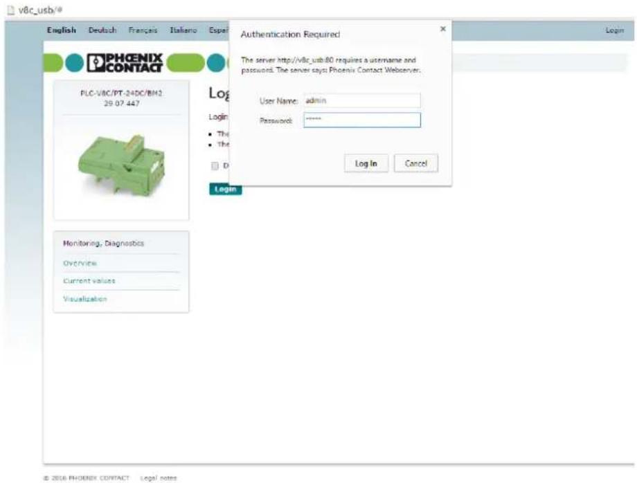
The configuration of the logic module is protected by a user name and password. To log into the logic module, click on the "Login" button in the top right corner.
Use the following for standard login:
- User name: admin
- Password: admin

Change the password during initial startup.
text_image
v8c_usb/ English Deutsch Français Italiano Espa PHOENIX CONTACT PLC-V8C/PT-24DC/BM3 29.07.447 Login User Name: admin Password: ****** Log In Cancel Login Monitoring, Diagnostics Overview Current values Visualization The server http://v8c.usb/80 requires a username and password. The server says: Phoenix Contact Webserver. Login © 2016 PHOENIX CONTACT Legal notesFigure 5-4 Login

If you cannot remember the password, you can recover the password via a support request. In order to recover the password, you need a recovery key, which is linked to the device serial number. The recovery key can be requested by e-mail from PHOENIX CONTACT Support (stating the device serial number): plclogic-service@phoenixcontact.com.
5.4.3 Configuration
5.4.3.1 General
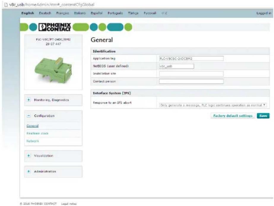
You can enter information for device identification on this page.
text_image
v8c_usb/homeAdmin.htm#_contentCfgGlobal English Deutsch Françie Italano Español Português Térkçe Pyccueh V.C PHOENIX CONTACT PLC-V8C/PT-24DC/BM2 29.07.447 General Identification Application tag PLC-V8CSC-24DCBM2 NetBIOS (user defined) v8c_usb Installation site Contact person Monitoring, Diagnostics Interface System (IFS) Response to an IFS abort Only generate a message, PLC logic continues operation as normal Configuration General Realtime clock Network Visualization Administration Factory default settings Save © 2016 PHOENIX CONTACT Legal notesFigure 5-5 General configuration settings
| Parameter | Description | Selection | Default setting |
| Application tag The application tag is used to clearly identify the components within the system. | - Min. 2 characters- Max. 32 characters- Letters or numbers | PLC-V8CSC-24DCBM or PLC-V8CPT-24DCBM or PLC-V8CSC-24DCSAM or PLC-V8CPT-24DCSAM | |
| NetBIOS (user defined) | The integrated web server of the logic module can be called in the web browser using this name (http://). | - Min. 2 characters- Max. 16 characters- Letters or numbers | v8c_usb |
| Installation site (optional) | Information regarding the installation location can be entered here. | – Min. 2 characters– Max. 32 characters– All Latin fonts and all standard special characters | |
| Contact person (optional) | Information regarding the contact person can be entered here. | – Min. 2 characters– Max. 32 characters– All Latin fonts and all standard special characters | |
| Response to an IFS abort | The behavior in the event of an IFS gateway connection abort can be defined here. | – Stop and reset all outputs– Only generate a message, PLC logic continues operation as normal | Only generate a message, PLC logic continues operation as normal |
5.4.3.2 Realtime clock
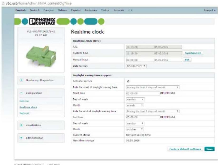
The realtime clock can be configured on this page.
You can synchronize the realtime clock with the system time of the connected computer or set it manually. You have the option of configuring the realtime clock so that it automatically switches to/from daylight saving time.
text_image
v8c_usb/homeAdmin.htm#_contentCfgTime English Deutsch Français Italiano Español Portugues Túrgè Pyeçaise 中文 Logged in PHOENIX CONTACT PLC-VBC/PT-24DC/BM2 29.07.447 Realtime clock Realtime clock (RTC) RTC 11:14:28 05.09.2019 System time 11:15:29 05.09.2016 Synchronize Manual input 00:00:00 05.09.2016 Set Data format DD.NH.YYYY▼ Monitoring, Diagnostics Configuration General Realtime clock Network Visualization Administration Daylight saving time support Activate service Rule for start of daylight saving time During the last 7 days of month Start time 02:00:00 (HH:HH:SS) Day of week sunday Month march Rule for end of daylight saving time During the last 7 days of month End time 03:00:00 (HH:HH:SS) Day of week sunday Month ocober Current status.Daylight saving time Next time change 30.10.2018 Factory default settings Save © 2016 PHOENIX CONTACT Legal notesFigure 5-6 Configuring the realtime clock
5.4.3.3 Network
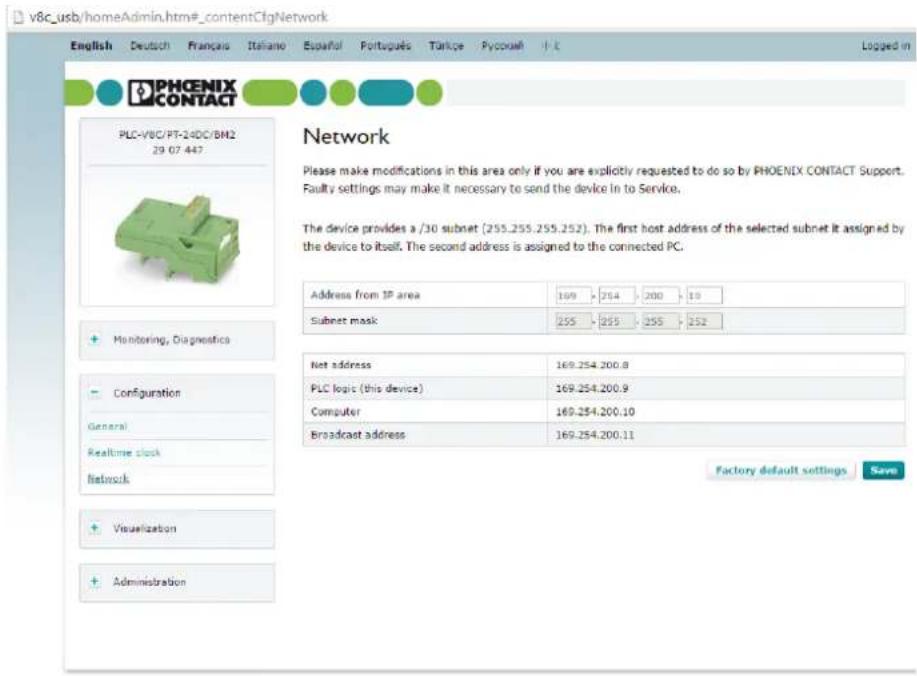
Settings for the IP address can be made on this page. Do not make changes in this area unless you have been specifically requested to do so by PHOENIX CONTACT Support. Incorrect settings may mean that the device has to be sent in for servicing.
The device provides a subnet (255.255.255.252). The device assigns the first host address of the selected subnet to itself. The second address is assigned to the connected PC.
text_image
v8c_usb/homeAdmin.htm#_contentCfgNetwork English Deutsch Français Italiano Español Portugues Térlice Pycoseli H.K. Logged in PHOENIX CONTACT PLC-V8C/PT-24DC/BM2 29 07 447 Network Please make modifications in this area only if you are explicitly requested to do so by PHOENIX CONTACT Support. Faulty settings may make it necessary to send the device in to Service. The device provides a /30 subnet (255.255.255.252). The first host address of the selected subnet is assigned by the device to itself. The second address is assigned to the connected PC. Address from IP area 169 254 200 19 Subnet mask 255 255 255 252 Monitoring, Diagnostics Configuration General Realtime clock Network Net address 169.254.200.8 PLC logic (this device) 169.254.200.9 Computer 169.254.200.10 Broadcast address 169.254.200.11 Factory default settings Save Visualization Administration© 2016 PHOENIX CONTACT Legal notes
Figure 5-7 Setting the IP address
| Parameter | Description | Selection | Default setting |
| Address from IP area Internet P | protocol address (IP address) of the connected computer | - M i n . 0- M a x . 2 5 | 169.254.200.105 |
5.4.4 Visualization
5.4.4.1 Configuration
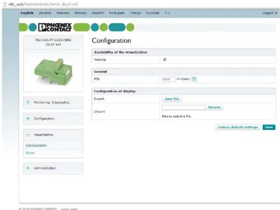
The basic visualization settings can be selected on this page.
text_image
v8c_usb/homeAdmin.htm#_dispConf English Deutsch Français Italiano Español Português Túrgipe Pyconelli 中文 PHOENIX CONTACT PLC-V8C/PT-24DC/BM2 29.07.447 Configuration Availability of the visualization Website ✓ General FIN 3000 (4 digits) 1 Configuration of display Export Save file Import Browse Please select a file. Factory default settings Save Monitoring, Diagnostics Configuration Visualization Configuration Editor AdministrationFigure 5-8 Visualization configuration
| Parameter | Description | Selection | Default setting |
| Website Choose whether or not | a visual-ization should be visible on the website | - On- Off | Off |
| PIN A pin can be assigned here | in order to protect individual visu-alization pages from external manipulation. | - 4 c h a r a c Emptye r s- N u m b e r s o n l y | |
| Export Export the active visualization configuration | - | ||
| Import | Import a previously exported configuration | - | |
5.4.4.2 Editor
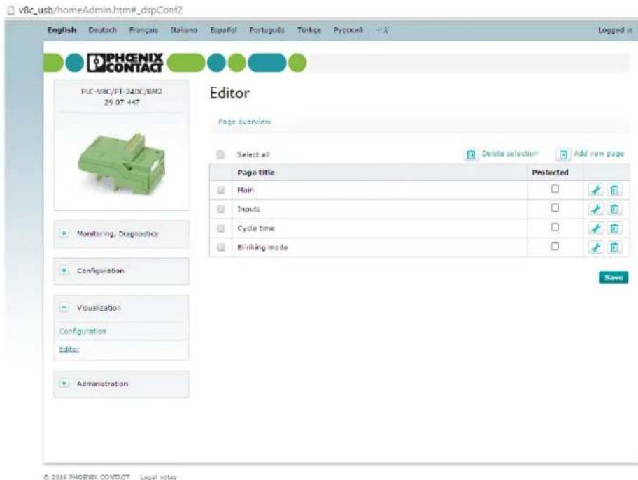
The available visualization pages are listed on this page. You can create new pages, delete existing ones or change the order of pages.
text_image
v8c_usb/homeAdmin.htm#_drpConf2 English Deutsch Français Italiano Español Português Túrlice Pytociaã 中文 PHOENIX CONTACT PLC-V8C/PT-24DC/BM2 29.07.447 Editor Page overview Select all Delete selection Add new page Page title Protected Main □ Inputs □ Cycle time □ Blinking mode □ Monitoring, Diagnostics Configuration Visualization Configuration Editor Administration SaveFigure 5-9 Editor - page overview
To open the configuration of individual visualization pages, click on the wrench icon.
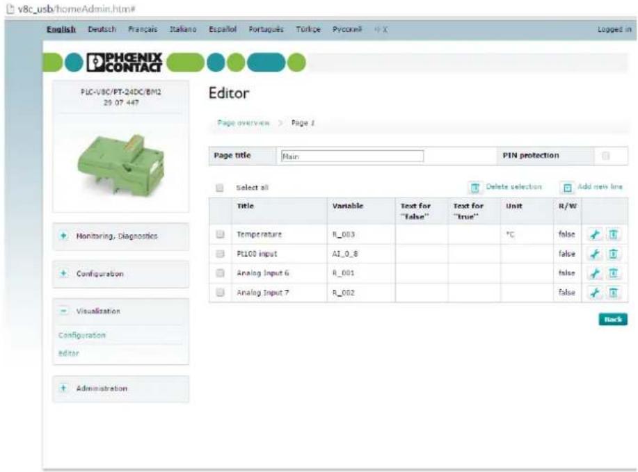
The 5 rows of a visualization page are listed here. You can edit each individual row, specify a title for the page, and activate PIN protection.
text_image
v8c_usb/homeAdmin.htm# English Deutsch Français Italiano Español Português Törkçe Pyccini® X PHOENIX CONTACT PLC-VBC/PT-24DC/BM2 29.07.447 Editor Page overview > Page 1 Page title Main PIN protection Select all Delete selection Add new line Title Variable Text for Text for Unit R/W Temperature B_003 "False" "True" °C false PILOO Input A1_0_8 false Analog Input 6 B_001 false Analog Input 7 B_002 false Monitoring, Diagnostics Configuration Visualization Configuration Editor Administration Back© 2016 PHOENIX CONTACT Legal Notes
Figure 5-10 Editor - page configuration
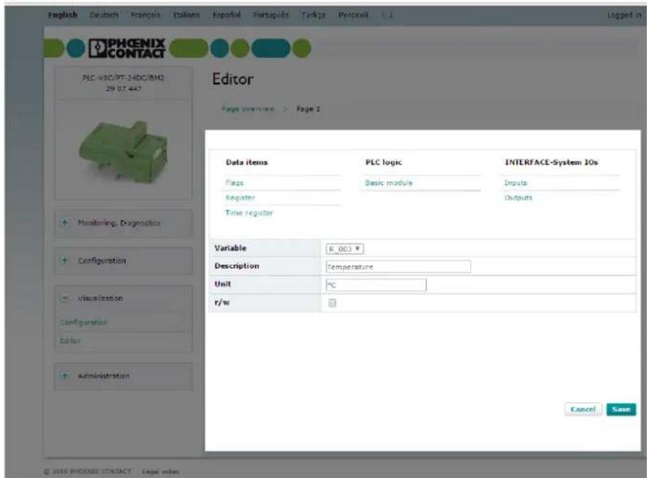
A variable from the active program can be displayed in each row.
The following variables are available:

- Time register
– All hardware inputs and outputs
- Interface system variables
v8c_usb/homeAdmin.htm#
text_image
English Deutsch Français Italama Españal Portiguats Turkgo Plyoscel Logged in PHOENIX CONTACT PLC-WBC/PT-24DC/BNQ 29 57 447 Editor Page overview > Page 2 Data items PLC logic INTERFACE-System IOs Flags Basic module Inputs Register Outputs Time register Monitoring, Diagnostics Configuration Visualization Configuration Editor Administration Variable R_003 # Description Temperature Unit °C r/w Cancel Save © 2016 PHOENIX CONTACT Legal IndexFigure 5-11 Editor - variables
5.4.5 Administration
5.4.5.1 Access control
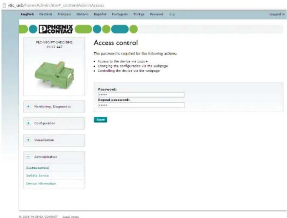
You can set the password for access control to the web server and LOGIC+ on this page.

NOTE:
If you forget the password, you must contact PHOENIX CONTACT Support by e-mail (stating the device serial number):
plclogic-service@phoenixcontact.com
text_image
v8c_usb/homeAdmin.htm#_contentAdminAccess English Deutsch Français Italiano Españal Portugues Turkje Pyccrvi 修改 PHOENIX CONTACT PLC-VBC/PT-24DC/BH2 29.07.447 Access control The password is required for the following actions: • Access to the device via Logic+ • Changing the configuration via the webpage • Controlling the device via the webpage Password: **** Repeat password: **** Save Monitoring, Diagnostics Configuration Visualization Administration Access control Update device Device information © 2016 PHOENIX CONTACT Legal notesFigure 5-12 Setting the password
| Parameter | Description | Selection | Default setting |
| Password Enter the new password | – Min. 2 characters | – Max. 32 characters– A - Z , a - | adminz , 0 - 9 |
| Repeat password Enter the new password again | – M i n . 2 c– Max. 32 characters– A - Z , a - | – M i n . 2 c– Max. 32 characters– A - Z , a - | adminr a c t ez , 0 - 9 |
5.4.5.2 Update device
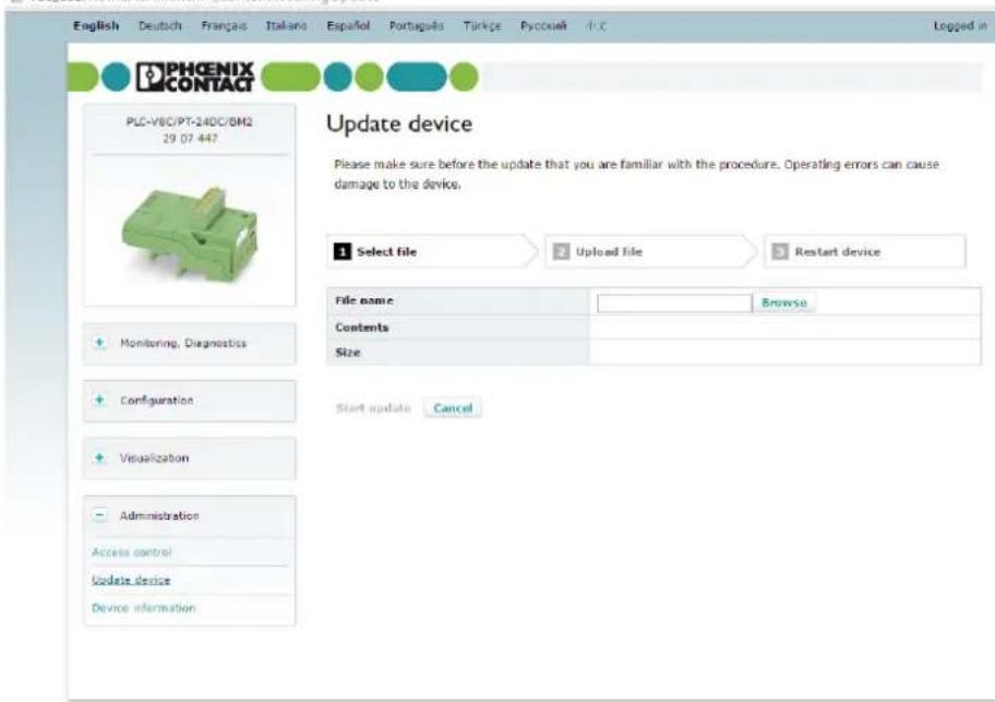
If new firmware or a new version of the web server is available for the basic module, you can start the update on this page.
Firmware updates have the file name "configFile.ee" and web server updates have the file name "WebServer.IMG".

Do not change the file name, as otherwise the update will not work.
v8c_usb/homeAdmin.htm®_contentWebImgUpdate
text_image
English Deutsch Français Italiana Español Portugés Turkçe Pyccueh iX Logged in PHOENIX CONTACT PLC-VBC/PT-24DC/BM2 29 07 447 Update device Please make sure before the update that you are familiar with the procedure. Operating errors can cause damage to the device. 1 Select file Upload file Restart device File name Browse Contents Size Monitoring, Diagnostics Configuration Visualization Administration Access control Update device Device information Start update Cancel© 2016 PHOENIX CONTACT Legal notes
Figure 5-13 Starting the firmware update
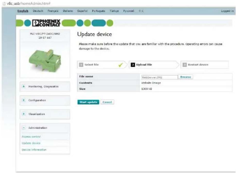
Click on the "Browse" button and then navigate to the storage location for the update.
The update can then be started if a valid file has been detected. To do this, click on the "Start update" button.
text_image
v8c.usb/homeAdmin.htm# English Deutsch Français Italiano Español Portugues Túrgue Pycorini iX Logged in PHOENIX CONTACT PLC-VBC/PT-24DC/BM2 29 07 447 Update device Please make sure before the update that you are familiar with the procedure. Operating errors can cause damage to the device. 1 Select file ✓ Upload file Restart device File name WebServer:IMG Browse Contents Website Image Size 1309 kB Monitoring, Diagnostics Configuration Visualization Administration Access control Update device Device information Start update Cancel© 2016 PHOENIX CONTACT Legal notes
Figure 5-14 Firmware update - selecting the file
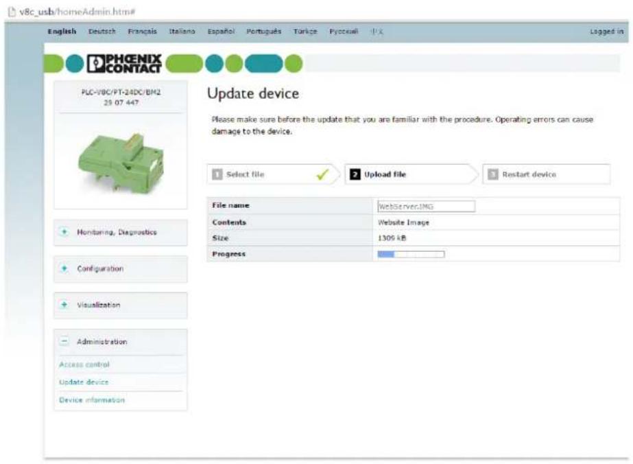
The current progress is displayed during the update.
text_image
v8c_usb/homeAdmin.htm# English Deutsch Français Italiano Español Portugues Türige Pyccuaft 中文 PHOENIX CONTACT PLC-1/BC/PT-24DC/BM2 29.07.447 Update device Please make sure before the update that you are familiar with the procedure. Operating errors can cause damage to the device. Select file Upload file Restart device File name WebServerIMG Contents Website Image Size 1305 kB Progress Monitoring, Diagnostics Configuration Visualization Administration Access control Update device Device informationFigure 5-15 Firmware update - progress indicator
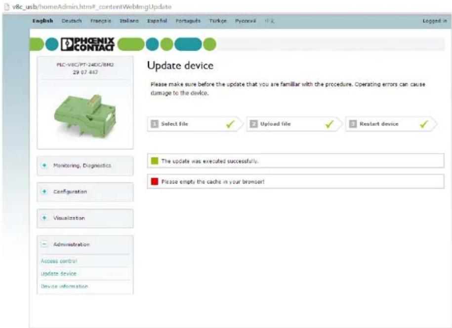
Following successful installation, the device restarts automatically. To view the active device configuration following restart, you must empty the browser cache (e.g., with Ctrl + Shift + Delete).
text_image
v8c_usb/homeAdmin.htm#_contentWebImgUpdate English Deutsch Français Italiano Españal Portugues Turkçe Pycorw# 中文 PHOENIX CONTACT PLC-V8C/PT-24DC/IBM2 29.07.447 Update device Please make sure before the update that you are familiar with the procedure. Operating errors can cause damage to the device. Select file Upload file Restart device Monitoring, Diagnostics Configuration Visualization Administration Access control Update device Device information The update was executed successfully. Please empty the cache in your browser!© 2016 PHOENIX CONTACT Legal notes
Figure 5-16 Firmware update - emptying the cache
5.4.5.3 Device information
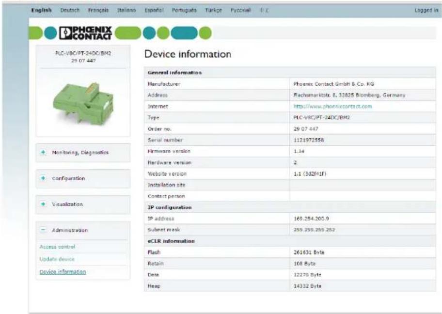
All important information is displayed on this page, such as:
- Serial number of the logic module
- Firmware version
- IP configuration
-eCLR information
v8c_usb/homeAdmin.htm#_contentAdminDeviceInfo
text_image
English Deutsch Français Italiano Españal Portugues Turkje Pyccxall PLC PHOENIX CONTACT PLC-VBC/PT-24DC/BM2 29 07 447 Device information General information Manufacturer Phoenix Contact GmbH & Co. KG Address Plachmarktrst. 8, 13825 Blomberg, Germany Internet http://www.phoenixcontact.com Type PLC-VBC/PT-24DC/BM2 Order no. 29 07 447 Serial number 1121972558 Firmware version 1.34 Hardware version 2 Website version 1:1 (342F41f) Installation site Contact person IP configuration IP address 169.254.200.9 Subset mask 255.255.255.252 eCLR information Flash 261631 Byte Retain 108 Byte Data 12276 Byte Heap 14332 Byte© 2016 PHOENIX CONTACT Legal notes
Figure 5-17 Overview of device information
5.5 Programming with LOGIC+
LOGIC+ is used for the configuration and programming of PLC logic. LOGIC+ allows you to conveniently develop the project on your own PC and to then send the project to the connected device and execute it. LOGIC+ supports you in every phase of project development, from project planning and configuration/parameterization to program start.

A detailed description of the LOGIC+ software can be found under "Help" in the software. Read this information carefully before creating your first project.
5.5.1 System requirements
The following software and hardware requirements must be met so that LOGIC+ can be executed on your PC under one of the operating systems listed.
Table 5-1 Windows 7 Service Pack 1
| Designation Description | |
| Processor 1 GHz or faster | 32-bit (x86) or 64-bit processor (x64) |
| RAM 2 GB, minimum | |
| Graphics card Microsoft DirectX 9 graphics card with WDDM driver | |
| .Net Framework 4.6 | The link to the download is provided in the setup routine. |
| Security updates KB30339 | 29 |
Table 5-2 Windows 8.1
| Designation Description | |
| Processor 1 GHz or faster | 32-bit (x86) or 64-bit processor (x64) |
| RAM 2 GB, minimum | |
| Graphics card Microsoft DirectX 9 graphics card with WDDM driver | |
| .Net Framework 4.6 | The link to the download is provided in the setup routine. |
Table 5-3 Windows 10
| Designation Description | |
| Processor 1 GHz or faster | 32-bit (x86) or 64-bit processor (x64) |
| RAM 2 GB, minimum | |
| Graphics card Microsoft DirectX 9 graphics card with WDDM driver | |
| .Net Framework 4.6 Is installed | |
Additional requirements
- Input devices: keyboard, mouse
- USB connection to connect the device
- Internet browser
5.5.2 Starting LOGIC+
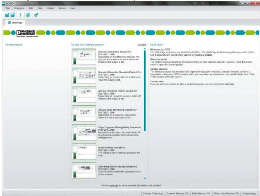
Following successful installation on the PC, open LOGIC+.
text_image
PHOENIX CONTACT Rearant projects Try one of our sample projects Go Back Need Help? Welcome to LOGIC* The Start Page welcomes you introducing LOGIC+. The Start Page is shown every time you start LOGIC+ and is automatically slowed when opening or updating a project. Recover projects The Project project list shows the projects that you have recently opened in LOGIC+. Only the project same to open the project. Sample projects The Sample projects list provides a list of proposed project templates. A project template contains a completely composed LOGIC+ project which you can adapt as required for your specific application. Click on the sample project is open it. Further help If you do not know what to do after a project is opened, you can find further help (help) Analog Comparator Sample for PLC-VSCU-JIM Depending on a threshold and a difference value the output is set. Analog Differential Threshold Switch S... PLC-VSCU-JIM Depending on a threshold and a difference value the output is set. Analog Threshold switch Sample for PLC-VSCU-JIM Depending on a switch-on and a switch-off threshold the output is set. Analog Value Monitoring Sample for PLC-VSCU-JIM Depending on a reference value and a difference value the output is set. Edge Triggered Wiping Relay Sample for PLC-VSCU-JIM By a pulse at the output, the output is set for an appropriate number after a power line (configuration) Inspector Relay Sample for PLC-VSCU-JIM The output is set or reset by a pulse of the CPU! Operating Figure Counter Sample for PLC-VSCU-JIM A counter block counts the operating hours of the program. Used now your app for more samples, templates, and updates!Figure 5-18 LOGIC+ start page
The start page is displayed when you open LOGIC+. The start page is closed automatically as soon as you open or create a project.
You should now familiarize yourself with LOGIC+ by calling "Help" in the menu bar.
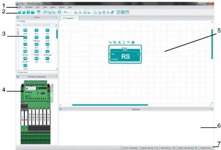
5.5.2.1 Description of the LOGIC+ interface
text_image
1 2 3 4 5 6 7 8 9 10 11 12 13 14 15 16 17 18 19 20 21 22 23 24 25 26 27 28 29 30 31 32 33 34 35 36 37 38 39 40 41 42 43 44 45 46 47 48 49 50 51 52 53 54 55 56 57 58 59 60 61 62 63 64 65 66 67 68 69 70 71 72 73 74 75 76 77 78 79 80 81 82 83 84 85 86 87 88 89 90 91 92 93 94 95 96 97 98 99 100Figure 5-19 LOGIC+ interface
Table 5-4 Areas of the LOGIC+ interface
| No. | Area Description | |
| 1 | Menu bar Provides access to the LOGIC+ commands and online help. | |
| 2 | Tool bar Provides access to frequently used commands. | |
| 3 | Toolbox Contains all elements that are required for programming.Elements from the toolbox are always added to the program by means of drag and drop. | |
| 4 | Hardware configuration Provides a graphical representation of the device. You can configure the inputs and outputs of the connected device here. | |
| 5 | Graphical editor Workspace where you develop your program. Graphical objects from the toolbox and input/output signals from the hardware configuration are inserted in the workspace and then connected by means of drag and drop. | |
| 6 | Message window Displays all messages output by LOGIC+. | |
| 7 | Status bar | Displays the status of the communication connection between the PC and the connected device, the number of errors and warnings, plus the memory used and the device status. |
Table 5-5 Buttons in the tool bar
| Icon Meaning Keyboard shortcut | ||
 | Create a new project Ctrl + N | |
 | Open an existing project Ctrl + O | |
 | Upload project sources from device | |
 | Add or remove libraries or disable libraries for the current project | |
 | Save the current project Ctrl + S | |
 | Close the current project | |
 | Print Ctrl + P | |
 | Create a new program | |
 | Rename or delete a program or change the program execution order | |
 | Open a program or switch to an open program | |
 | Open the data item editor | |
 | Undo Ctrl + Z | |
 | Redo Ctrl + Y | |
 | Increase size of object displayed in the active program window | |
 | Decrease size of object displayed in the active program window | |
 | Resize contents of active window to the default size | |
 | Displays the full contents in the current window size | |
Table 5-5 Buttons in the tool bar [...]
| Icon | Meaning | Keyboard shortcut |
 | Execute program on simulated device F5 | |
 | Execute program on the device | |
 | Stop program execution and reset the device | |
 | Open the communication settings | |
 | Configure the hardware settings | |
 | Show or hide the toolbox window | |
| [53SH] | Show or hide the hardware configuration | |
 | Show or hide the message window | |
 | Resume execution Alt + F5 | |
 | Pause execution Shift + F5 | |
 | Execute a step in the procedure F10 | |
 | Switch to the breakpoint at the current point F9 | |
 | Remove all breakpoints in the active program worksheet | |
 | Activate/deactivate breakpoint at the current position | |
 | Lock all breakpoints in the active program worksheet | |
 | Switch back to programming Ctrl + F5 | |
 | Show or hide the watch window |
5.5.3 Hardware configuration

NOTE:
PLC logic does not check that the hardware view in LOGIC+ matches the actual hardware. The hardware configuration in LOGIC+ and the configuration of the connected device on which the project is to be executed must be identical. This means that the arrangement of the segments and the assignment of the inputs and outputs in the hardware configuration in LOGIC+ and for the connected device must be the same.
Make sure that both configurations match. Otherwise this may result in undesirable behavior in the application. Make sure that this will not lead to any hazardous situations.
The hardware configuration in LOGIC+ can be used to configure each channel as an input or output with electromechanical relays, solid-state relays or analog terminal blocks.
For more details, refer to the help in LOGIC+.
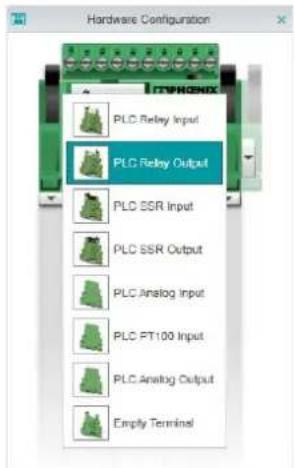
text_image
Hardware Configuration PLC Relay Input PLC Relay Output PLC SSR Input PLC SSR Output PLC Analog Input PLC PT100 Input PLC Analog Output Empty TerminalFigure 5-20 Hardware configuration
5.5.4 Function blocks
As described in the LOGIC+ help, programs can be created in function block diagram (FBD) or ladder diagram (LD). The following function blocks are available in LOGIC+ for both languages.
Table 5-6 Available functions/function blocks
| Block Description | |
| ABS | Mathematical calculation of the absolute value |
| ADD | Mathematical addition |
| AND | Logical AND |
| Counter | Up/down counter |
| DIV | Mathematical division |
| EQ | “Is equal” comparator |
| FallEdge | Detect falling edge |
| GE “Greater than or equal to” comparator | |
| GT | “Greater than” |
| LE “Less than or equal to” comparator | |
| LIMITER | Limit value to minimum and maximum |
| LT | “Less than” comparator |
| MAX | Detect maximum value |
| MIN | Detect minimum value |
| MOD | Division with remainder |
| MUL | Mathematical multiplication |
| NOT | Invert state |
| OffDelay | Timer for switch-off delay |
| OnDelay | Timer for switch-on delay |
| OR | Logical OR |
| PulseGen | Pulse generator |
| PulseTimer | Output pulse with a defined pulse length |
| Random | Random number generator |
| Reset | Self-holding relay with reset priority |
| RiseEdge | Detect rising edge |
| SELECT | Selection function |
| Set | Self-holding relay with set priority |
| SUB | Mathematical subtraction |
| WeekTimer | Weekly timer |
| XOR | Exclusive OR |
5.5.5 Memory required for functions/function blocks
The logic module has 228,863 bytes of program memory available and 11,024 bytes of mass storage available.
Table 5-7 Memory required for standard functions/function blocks
| Function/function block Program memory Mass storage | |||
| ABS (first instance) 5388 bytes | 5132 bytes 0 bytes | ||
| ABS (subsequent instance) 160 bytes 76 bytes 0 bytes | |||
| ADD 284 bytes 4 bytes 0 bytes | |||
| AND 288 bytes 4 bytes 0 bytes | |||
| Counter (first instance) 1256 bytes 816 bytes | 64 bytes | ||
| Counter (subsequent instance) | 176 bytes 96 bytes | 64 bytes | |
| DIV | 308 bytes 32 bytes | 0 bytes | |
| EQ | 272 bytes 4 bytes | 0 bytes | |
| FallEdge (first instance) | 2256 bytes 1980 bytes | 64 bytes | |
| FallEdge (subsequent instance) | 192 bytes 104 bytes | 64 bytes | |
| GE | 292 bytes 16 bytes | 0 bytes | |
| GT | 276 bytes 4 bytes | 0 bytes | |
| LE | 292 bytes 16 bytes | 0 bytes | |
| LIMITER (first instance) | 7296 bytes 6960 bytes | 0 bytes | |
| LIMITER (subsequent instance) | 296 bytes 144 bytes | 0 bytes | |
| LT | 276 bytes 4 bytes | 0 bytes | |
| MAX (first instance) | 5620 bytes 5358 bytes | 0 bytes | |
| MAX (subsequent instance) | 232 bytes 108 bytes | 0 bytes | |
| MIN (first instance) | 5612 bytes 5336 bytes | 0 bytes | |
| MIN (subsequent instance) | 220 bytes 108 bytes | 0 bytes | |
| MOD | 300 bytes 36 bytes | 0 bytes | |
| MUL 280 bytes 4 bytes 0 bytes | |||
| NOT 264 bytes 8 bytes 0 bytes | |||
| OffDelay (first instance) | 2764 bytes 2400 bytes | 144 bytes | |
| OffDelay (subsequent instance) | 288 bytes 116 bytes | 144 bytes | |
| OnDelay (first instance) | 2780 bytes 2416 bytes | 144 bytes | |
| OnDelay (subsequent instance) | 284 bytes 112 bytes | 144 bytes | |
| OR | 272 bytes 4 bytes | 0 bytes | |
| PulseGen (first instance) 1432 bytes | 1048 bytes | 88 bytes | |
Table 5-7 Memory required for standard functions/function blocks [...]
| Function/function block | Program memory | Mass storage | |
| With program sources | Without program sources | ||
| PulseGen (subsequent instance) | 296 bytes 116 bytes | 88 bytes | |
| PulseTimer (first instance) 2964 bytes 2608 bytes | 144 bytes | ||
| PulseTimer (subsequent instance) | 292 bytes 116 bytes | 144 bytes | |
| Random (first instance) 1676 bytes 1288 bytes 112 bytes | |||
| Random (subsequent instance) | 164 bytes 96 bytes | 112 bytes | |
| Reset (first instance) 2308 bytes 1980 bytes 64 bytes | |||
| Reset (subsequent instance) | 136 bytes 96 bytes | 64 bytes | |
| RiseEdge (first instance) 2272 bytes 1964 bytes 64 bytes | |||
| RiseEdge (first instance) 132 bytes 100 bytes 64 bytes | |||
| SELECT (first instance) 2956 bytes 2672 bytes 0 bytes | |||
| SELECT (subsequent instance) | 268 bytes 112 bytes | 0 bytes | |
| Set (first instance) 2304 bytes | 1980 bytes 64 bytes | ||
| Set (subsequent instance) 140 bytes 92 bytes 64 bytes | |||
| SUB | 264 bytes 4 bytes | 0 bytes | |
| WeekTimer (first instance) 5104 bytes 4068 bytes | 524 bytes | ||
| WeekTimer (subsequent instance) | 476 bytes 100 bytes | 524 bytes | |
| XOR | 280 bytes 4 bytes | 0 bytes | |
Table 5-8 Memory required for Interface System V1.1
| Function/function block | Program memory | Mass storage | |
| With program sources | Without program sources | ||
| Check16Bit (first instance) | 1114 bytes | 748 bytes 64 bytes | |
| Check16Bit (subsequent instance) | 156 bytes | 100 bytes 64 bytes | |
| FlagsToIFS (first instance) | 2000 bytes | 1460 bytes 120 bytes | |
| FlagsToIFS (subsequent instance) | 268 bytes | 100 bytes 120 bytes | |
| IFSToFlags (first instance) | 2108 bytes | 1560 bytes 120 bytes | |
| IFSToFlags (subsequent instance) | 268 bytes | 100 bytes 120 bytes | |
Table 5-9 Memory required for Analog V1.1
| Function/function block Program memory Mass storage | |||
| AnalogFilter (first instance) 107 | 6 bytes 700 bytes | 80 bytes | |
| AnalogFilter (subsequent instance) | 160 bytes 104 bytes | 80 bytes | |
| DifferentialThresholdSwitch (first instance) | 1120 bytes 748 bytes | 64 bytes | |
| DifferentialThresholdSwitch (subsequent instance) | 184 bytes 116 bytes | 64 bytes | |
| MinMaxAvg (first instance) 429 | 6 bytes 3868 bytes | 280 bytes | |
| MinMaxAvg (subsequent instance) | 166 bytes 100 bytes | 280 bytes | |
| MinMaxHold (first instance) 10 | 32 bytes 660 bytes | 56 bytes | |
| MinMaxHold (subsequent instance) | 160 bytes 100 bytes | 56 bytes | |
| MoveAvg (first instance) 2476 | bytes 2104 bytes | 104 bytes | |
| MoveAvg (subsequent instance) | 156 bytes 96 bytes | 104 bytes | |
| Multiplexer (first instance) 1168 | bytes 764 bytes | 72 bytes | |
| Multiplexer (subsequent instance) | 180 bytes 100 bytes | 72 bytes | |
| PIDControl (first instance) 2108 | bytes 1620 bytes | 160 bytes | |
| PIDControl (subsequent instance) | 212 bytes 104 bytes | 160 bytes | |
| Pt 100 (first instance) 2488 bytes | 2132 bytes 88 bytes | ||
| Pt 100 (subsequent instance) | 140 bytes 96 bytes | 88 bytes | |
| Pt 1000 (first instance) | 2580 bytes 2228 bytes | 88 bytes | |
| Pt 1000 (subsequent instance) | 144 bytes 96 bytes | 88 bytes | |
| PWM (first instance) | 1864 bytes 1456 bytes | 144 bytes | |
| PWM (subsequent instance) | 160 bytes 92 bytes | 144 bytes | |
| Ramp (first instance) | 1828 bytes 1368 bytes | 120 bytes | |
| Ramp (subsequent instance) | 196 bytes 99 bytes | 120 bytes | |
| ScaleAnalogIn (first instance) | 1460 bytes 1052 bytes | 96 bytes | |
| ScaleAnalogIn (subsequent instance) | 180 bytes 104 bytes | 96 bytes | |
| ScaleAnalogOut (first instance) | 1480 bytes 1068 bytes | 96 bytes | |
Table 5-9 Memory required for Analog V1.1
| Function/function block | Program memory | Mass storage | |
| With program sources | Without program sources | ||
| ScaleAnalogOut (subsequent instance) | 476 bytes 104 bytes | 96 bytes | |
| ThresholdSwitch (first instance) | 2688 bytes 2304 bytes | 96 bytes | |
| ThresholdSwitch (subsequent instance) | 172 bytes 104 bytes | 96 bytes | |
Table 5-10 Memory required for Special V1.2
| Function/function block Program memory Mass storage | |||
| CycleTime (first instance) 1052 bytes 744 bytes 64 bytes | |||
| CycleTime (subsequent instance) | 140 bytes 100 bytes 64 bytes | ||
| ImpulseRelay (first instance) 2284 bytes 1976 bytes 72 bytes | |||
| ImpulseRelay (subsequent instance) | 144 bytes 104 bytes 72 bytes | ||
| MemoryNumber (first instance) | 238 bytes 2020 bytes 96 bytes | ||
| MemoryNumber (subsequent instance) | 156 bytes 104 bytes 96 bytes | ||
| MemoryTime (first instance) 2376 bytes 2012 bytes 96 bytes | |||
| MemoryTime (subsequent instance) | 144 bytes 100 bytes 96 bytes | ||
| OffDelayReset (first instance) | 1256 bytes 872 bytes 88 bytes | ||
| OffDelayReset (subsequent instance) | 160 bytes 104 bytes 88 bytes | ||
| RetainCounter (first instance) | 3764 bytes 3320 bytes 224 bytes | ||
| RetainCounter (subsequent instance) | 228 bytes 144 bytes 224 bytes | ||
| ShiftRegister (first instance) | 2768 bytes | 2312 bytes | 96 bytes |
| ShiftRegister (subsequent instance) | 192 bytes 104 bytes 96 bytes | ||
| ShutterControl (first instance) | 5356 bytes 4820 bytes 480 bytes | ||
| ShutterControl (subsequent instance) | 228 bytes 104 bytes 480 bytes | ||
| WipingRelay (first instance) | 2724 bytes 2368 bytes 144 bytes | ||
| WipingRelay (subsequent instance) | 144 bytes 100 bytes 144 bytes | ||
5.5.6 Data item types in LOGIC+
Table 5-11 Data item types
| Name Description Value range | ||
| Flags The flag name consists of the string “F_xxx” (where xxx = 0...127) and, if defined, the identifier. A maximum of 128 flags can be used in a project. | Value is set to TRUE or FALSE (1 or 0, ON or OFF). | |
| Registers The register name consists of the string “R_xxx” (where xxx = 0...127) and, if defined, the identifier. A maximum of 128 registers can be used in a project. | Numerical value (integer value only)-2,147,483,648 to 2,147,483,647 | |
| Digital inputs Digital inputs have the designation “DI_x_y”, where x is the station number (basic logic module = 0) and y is the input number. The number of available digital inputs depends on the device configuration.See “Inputs and outputs” on page 34 | Value is set to TRUE or FALSE (1 or 0, ON or OFF). | |
| Digital outputs Digital outputs have the designation “DQ_x_y”, where x is the station number (basic logic module = 0) and y is the output number. The number of available digital outputs depends on the device configuration.See “Inputs and outputs” on page 34 | Value is set to TRUE or FALSE (1 or 0, ON or OFF). | |
| Analog inputs Analog inputs are used to monitor voltages or values. Analog inputs have the designation “AI_x_y”, where x is the station number (basic logic module = 0) and y is the input number. The number of available analog inputs depends on the device configuration.See “Inputs and outputs” on page 34 | Numerical value (integer value only).Value range: 0 to 1000The analog inputs at IN6 and IN7 process 0 V ... 10 V input signals.PLC logic analog values: 0 V ... 10 VValues in LOGIC+: 0 ... 1000Voltage values in 10 mV increments can therefore be read from PLC logic in LOGIC+. | |
| Analog outputs Analog outputs are used to output voltages or currents.Analog outputs have the designation “AQ_x_y”, where x is the station number (basic logic module = 0) and y is the output number. The number of available analog outputs depends on the device configuration.See “Inputs and outputs” on page 34 | 0 V ... 10 V or 2 V ... 10 V voltage 0 mA ... 20 mA or 4 mA ... 20 mA current | |
| Interface system inputs | Inputs that come from a gateway have the designation IFS_Input_x (where x = 0...15).See “Communication with PLC logic” on page 91 | Numerical value (integer value only)-32,768 ... 32,767 (signed INT)0 ... 65,535 (unsigned INT) |
| Interface system outputs | Outputs that are transferred to a gateway have the designation IFS_Output_x (where x = 0...15).See “Communication with PLC logic” on page 91 | Numerical value (integer value only)-32,768 ... 32,767 (signed INT)0 ... 65,535 (unsigned INT) |
5.5.7 Connecting the device to LOGIC+
Connect the device to the PC.
Make sure the device is detected by LOGIC+.
You can now perform the following actions:
- Execute a project on the device
- Monitor a project in online mode
- Set device parameters
- Upload project sources from the device
Here, connection means that:
- The device must be connected to the PC on which LOGIC+ is executed via a USB cable.
- You must set the communication parameters in LOGIC+ so that LOGIC+ can access the device.
Use a USB cable to connect PLC logic to a free USB connection on your PC on which LOGIC+ is running. To open the "Communication Settings" dialog, select "File > Communication Settings" or click on the "Communication Settings" button in the tool bar.
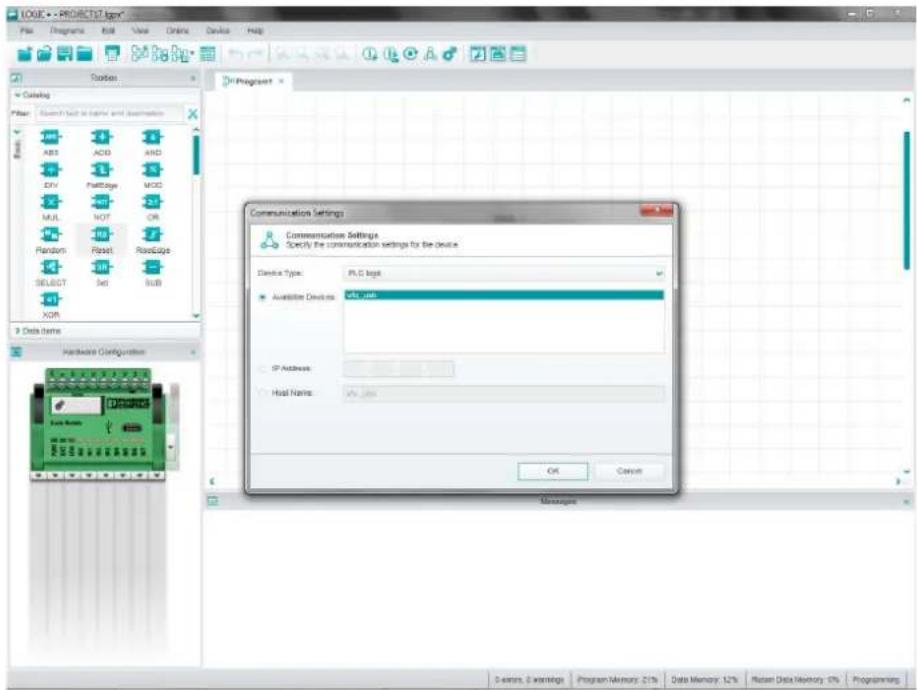
text_image
LOGE - PROJETO12.logre File Edit Programs Roll View Online Device Help Tools Catalog Filter Search List to Inside and Demonstrate ABS ACIB AND DVY Partridge MDD MULT NOT OR Random Float Roadcape SELECT Set RGB XOR 3 Data Items Hardware Configuration Communication Settings Specify the communication settings for the device Device Type: PLC logit Available Devices: 0% port IP Address: Host Name: OK Cancel Messages S errors, E warnings Program Memory: 21% Data Memory: 12% Reset Data Memory: 0% ProgrammingFigure 5-21 Communication settings
In the "Communication Settings" dialog, select the device that is connected to your PC in the "Selected Device" list box. The device name corresponds to the NetBIOS name specified on the device configuration page. The default NetBIOS name is "v8c_usb".
For information on how to open the configuration page and change the NetBIOS name, see "Configuration via web server" on page 50.
As soon as LOGIC+ detects the connected device at the USB connection, the message
"The device
Figure 5-21 on page 79). If the device is not found, a corresponding message appears in the dialog. If so, check whether the device is connected correctly to the PC or select a different device.
You can cancel this operation with "Cancel". To close the "Communication Settings" dialog again, click on "OK".
5.5.8 Executing a project on PLC logic

NOTE:
The project is immediately executed (started) on the device. Online mode is activated when you click on the "Execute on device" button. Make sure that this will not lead to any hazardous situations.
The integrated simulation can be used to test the behavior of the project with no device connected.
Password protection
The project is protected against unauthorized transfer and execution on the device with a password. This password is checked every time the "Execute on device" command is performed. The device password can be changed on the device configuration page. For information on how to open this page and change the password, see "Configuration via web server" on page 50.
To execute the project on the device and switch to online mode, proceed as follows:
-
Make sure that there are no error messages regarding the project in the message window.
-
Make sure that the configuration of the inputs and outputs in the hardware configuration corresponds to the configuration of the inputs and outputs on the device. If this is not the case, change the hardware configuration in LOGIC+.
-
Select "Online > Execute on device" or click on the "Execute on device" button in the tool bar.
-
In the dialog that appears, the memory required is displayed and you can select the "Include sources" option. If you select this option, when the compiled project is transferred to the logic module, the original LOGIC+ project is also transferred together with all comments and identifiers.
You can also download the project again later directly from the logic module.
After successfully transferring and starting the project on the device, online mode is activated. The watch window appears at the bottom of the program window. The tool bar contains additional buttons which can be used to control the device and debug the active project. The status bar displays the states "Running" and "Device connected".
While the project is being executed on the device and online mode is activated, you can perform the following actions:
– Monitor the active project in online mode
- Stop and resume the active project
- Debug the project by overwriting values
– Group data items and inputs/outputs from several programs in the watch window in order to view their online values at a glance
- Debug the project
To return to programming mode, click on the "Back to programming" button in the tool bar. Alternatively, use the keyboard shortcut
Behavior during transfer
LOGIC+ behaves differently when a project is executed.
Its behavior depends on the following factors:
- The current device status indicated in the status bar: for example, a project is being cyclically executed on the device or project execution has been stopped.
- The project loaded in the internal memory of the device.
The following generally applies:
Each time the "Execute on device" button is pressed, LOGIC+ checks whether a project is already stored on the device. If the project on the device and the project to be transferred are not identical, the device is reset. The current project is transferred to the device and executed immediately. If the project on the device and the LOGIC+ project are identical, the project is executed immediately.
5.5.9 Memory and size of a program
The project size is limited by the memory available on the connected device. During programming, LOGIC+ monitors the memory used. The current memory used on the device is indicated by a percentage value in the status bar.
Among other things, the project size depends on the number of different function blocks.
5.5.10 Cycle time
The cycle time is the time required to process a complete program once. The time required for one program cycle can be determined by means of the following example program.
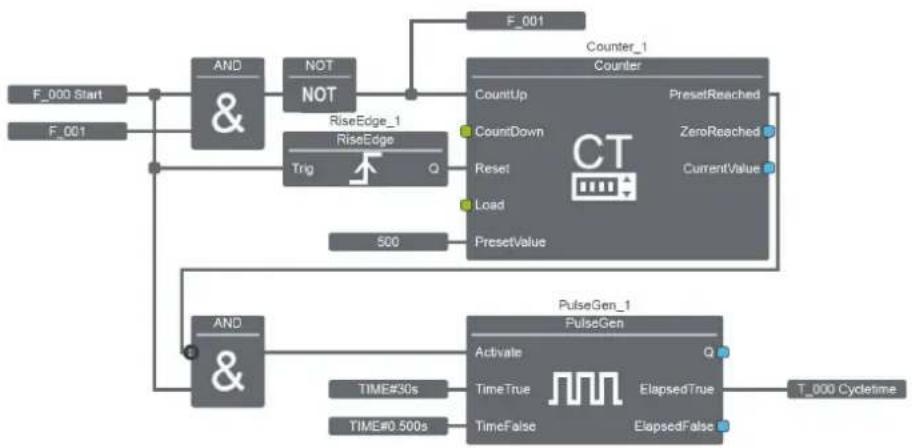
flowchart
graph TD
    A["F_000 Start"] --> B["AND &"]
    C["F_001"] --> B
    B --> D["NOT NOT"]
    D --> E["RiseEdge_1"]
    E --> F["Trig"]
    F --> G["500"]
    G --> H["PresetValue"]
    I["F_001"] --> J["Counter_1 Counter"]
    K["CountUp"] --> L["CountDown"]
    M["Reset"] --> N["Reset"]
    O["Load"] --> P["Load"]
    Q["PresetReached"] --> R["ZeroReached"]
    S["CurrentValue"] --> T["CurrentValue"]
    U["T_000 Cycletime"] --> V["PulseGen_1 PulseGen"]
    W["AND &"] --> X["TIME#30s"]
    W --> Y["TIME#0.500s"]
    X --> Z["TimeTrue"]
    X --> AA["TimeFalse"]
    Z --> AB["ElapsedTrue"]
    Z --> AC["ElapsedFalse"]
    AD["ClockUp"] --> AE["CountUp"]
    AF["Reset"] --> AG["Reset"]
    AH["PresetValue"] --> AI["PresetValue"]
Figure 5-22 Determining the cycle time
This example program can be inserted in programs that have already been created. The example program indicates the cycle time of the program created. Overwrite flag "F_000_Start" with TRUE to start the calculation. The program counts 1000 cycles and indicates the time required for this in time register "T_000 Cycletime". This value must then be divided by 1000 to determine the value for one cycle.
Example: T_000 indicates the value "T#1.996s".
The cycle time is therefore 1.996 ms.

Alternatively, you can use the CycleTime function block from the "Special" library. The library is available to download free of charge at phoenixcontact.com.
5.6 IFS-CONFSTICK (memory)
PLC logic programs are stored using the IFS-CONFSTICK memory module (Order No. 2986122) or programs can be easily transferred to other devices.
If settings such as time or date are required on the new device, these values can be configured via the integrated web server. The new device does not need access to the LOGIC+ software for this.
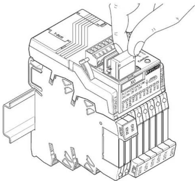
text_image
T-USB XO PLC DOUT INT INT INT INT INT INT INT INT INT INT INT INT INT INT INT INT INT INT INT INT INT INT INT INT INT INT INT INT INT INT INT INT INT INT INT INT INT INT INT INT INT INT INT INT INT INT INT INT INT INT INP INP INP INP INP INP INP INP INP INP INP INP INP INP INP INP INP INP INP INP INP INP INP INP INP INP INP INP INP INP INP INP INP INPFigure 5-23 Inserting the IFS-CONFSTICK
5.6.1 Writing the device configuration and program to the IFS-CONFSTICK
-
Press the Confirm button on the logic module.
-
Insert the memory module in the logic module within 4 s.
The copying of the configuration and program is started.
The DAT LED flashes while saving.
The DAT LED goes out when backup is completed.
- Remove the memory module.
5.6.2 Running the device configuration and program on the logic module
-
Insert the memory module in the logic module. The configuration/program is checked automatically. If another configuration/program is detected on the device, the DAT and ERR LEDs flash alternately.
-
Press the Confirm button within 6 s. The copying of the configuration and program is started (DAT LED flashes). An automatic restart is then performed (PWR and ERR LEDs flash simultaneously). When the PWR LED is permanently on, this means that the process has been completed.
5.7 Configuration and monitoring via Bluetooth
5.7.1 Bluetooth adapter
The IFS-BT-PROG-ADAPTER Bluetooth adapter (Order No. 2905872) can be used to establish a wireless connection between PLC logic and a smartphone with Android or iOS. To do this, insert the Bluetooth adapter with S-PORT interface into the Memory socket.
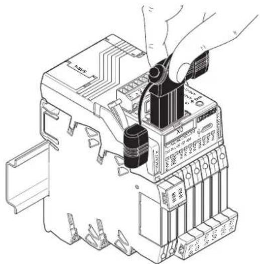
text_image
Technical diagram of an electrical contactor with labeled components and hands installing or adjusting the main body.Figure 5-24 Bluetooth adapter
5.7.2 PLC logic app
Downloading the app
The PLC logic app is available in the Google Play Store and Apple App Store.
Establishing the connection to the Bluetooth adapter
When you start the PLC logic app, it searches for available Bluetooth adapters. The Bluetooth adapters found are displayed in a list.
Further help for the PLC logic app can be found in the app itself.
5.8 Integration in third-party bus systems using the example of PROFIBUS DP
An adaptable EM-PB-GATEWAY-IFS, which is available as an option, can be used to integrate PLC logic into a PROFIBUS DP network. This enables communication with a higher-level controller for remote control, diagnostics, and visualization purposes.
The following components are required for this.
Table 5-12 Components for integration in PROFIBUS DP
| Description Order No. Order designation | ||
| Gateway for PROFIBUS DP 2297620 EM-PB-GATEWAY-IFS | ||
| Programming adapter for the PROFIBUS gateway | 2320500 IFS-USB-DATACABLE | |
| DIN rail connector 2707437 ME22,5 TBUS 1,5/5-ST- | 3,81 GN | |
| Connecting cable for connecting PLC logic to the DIN rail connector, length: 30 cm | 2905263 PLC-V8C/CAB/TBUS/0,3M | |
The following downloads are also required.
Go to phoenixcontact.com and enter "EM-PB-GATEWAY-IFS" or "2297620" in the search field. The following tools can be found under Downloads:
- IFS-CONF-SUITE-INTERFACE Setup
- GSD file for EM-PB-GATEWAY-IFS
5.8.1 Mounting
- Snap the DIN rail connector onto the DIN rail.
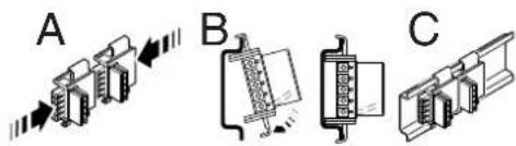
text_image
A B C- Snap the gateway onto the DIN rail connector.
The gateway is positioned mechanically using the DIN rail connector. The connections on the bottom of the gateway make contact with the connections on the DIN rail connector.
- Connect the T-BUS connection on the PLC-V8C logic module to the DIN rail connector using the appropriate PLC-V8C/CAB/TBUS/0,3M cable (Order No. 2905263).
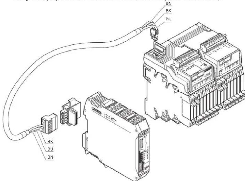
text_image
BN BK BU BK BU Bk BU BNFigure 5-25 Mounting the PROFIBUS gateway and PLC logic
Due to the design, only one PLC logic device can be connected to the gateway. Therefore in this combination, only one PLC logic device can be integrated into a PROFIBUS network.
5.8.2 EM-PB-GATEWAY-IFS gateway
Before starting up the gateway, carefully read through the packing slip supplied with the device. For detailed information on the gateway, refer to the gateway system manual available at phoenixcontact.net/products.
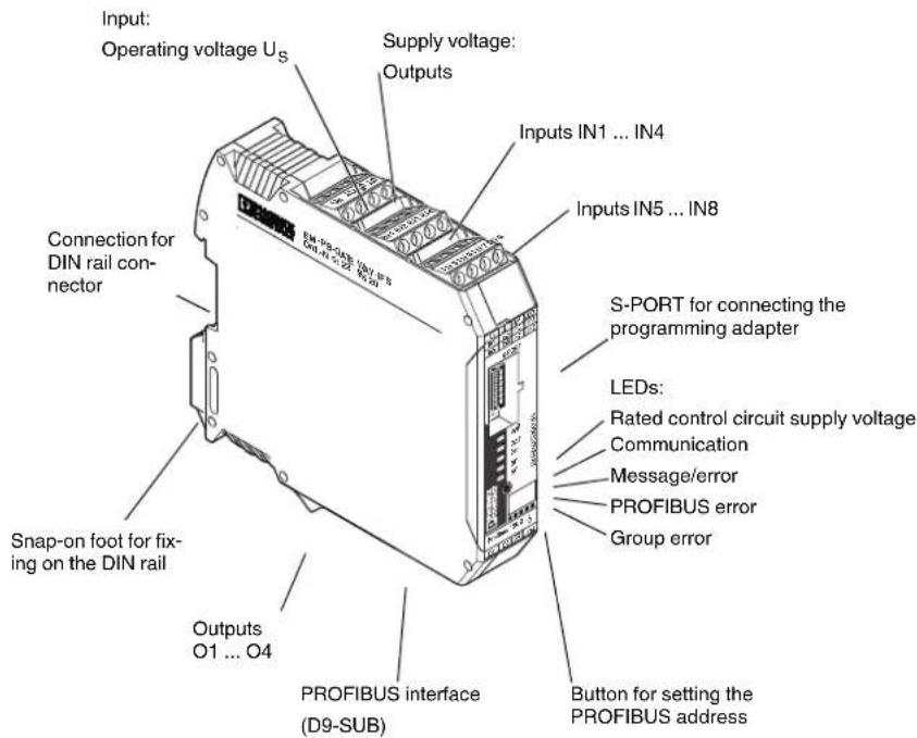
text_image
Input: Operating voltage Us Supply voltage: Outputs Inputs IN1 ... IN4 Inputs IN5 ... IN8 S-PORT for connecting the programming adapter LEDs: Rated control circuit supply voltage Communication Message/error PROFIBUS error Group error Output O1 ... O4 PROFIBUS interface (D9-SUB) Button for setting the PROFIBUS address Connection for DIN rail connector Snap-on foot for fix- ing on the DIN railFigure 5-26EM-PB-GATEWAY-IFS
The EM-PB-GATEWAY-IFS PROFIBUS module (Order No. 2297620) is a module that enables PLC logic to be connected to PROFIBUS DP. The module is certified according to specification DPV1 (EN 50170). The EM-PB-GATEWAY-IFS can communicate with PLC logic via the DIN rail connector and an appropriate connecting cable. The assignment of the process data can be individually adapted to the application requirements by means of the GSD file (device master data). The GSD file (containing the characteristic communication features of the PROFIBUS module) is available on the Internet at phoenixcontact.net/products. The PROFIBUS address is set using a button and a device (PC, memory stick, actuator) connected to the S-PORT as an option. The module does not provide PROFIBUS termination. An appropriate connector should be used for this, if required.
5.8.3 Block diagram
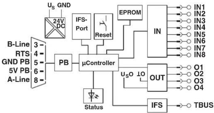
flowchart
graph TD
    A["24V DC"] --> B["PB"]
    C["B-Line 3"] --> D["μController"]
    E["RTS 4"] --> D
    F["GND PB 5"] --> D
    G["5V PB 6"] --> D
    H["A-Line 8"] --> D
    I["US GND"] --> J["IFS-Port"]
    K["Reset"] --> L["μController"]
    M["Status"] --> N["μController"]
    O["EPROM"] --> P["IN"]
    Q["OUT"] --> R["IN1 IN2 IN3 IN4 IN5 IN6 IN7 IN8 OUT"]
    S["IFS"] --> T["TBUS"]
    U["USO LO"] --> V["μController"]
Figure 5-27 Block diagram
5.8.4 Status LEDs
Five LEDs visualize the various operating states of the gateway.

The status LEDs are used to indicate the PROFIBUS address and the addresses of the connected IFS devices in parameterization mode when setting the address.
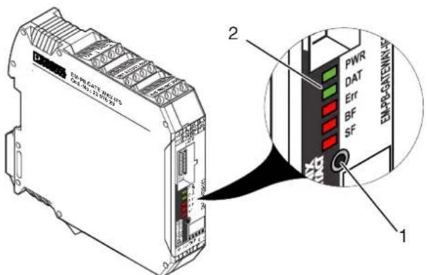
text_image
2 1Figure 5-28 Status LEDs
1 Button for setting the PROFIBUS address
2 Status LEDs
| LED Description | |
| PWR LED (green)OffOnFlashing at 1.4 Hz (slow)Flashing at 2.8 Hz (fast) | Device statusNo supply voltage. Microcontroller does not start.Supply voltage OK. Microcontroller is running.Setting the PROFIBUS addressIFS address assignment |
| LED [...] Description | |
| DAT LED (green)OffOnFlashing at 1.4 Hz (slow) | CommunicationNo data trafficCyclic data trafficDevice is being configured |
| ERR LED (red)OffOnFlashing at 2.8 Hz (fast) | Device or process errorNo errorSerious internal errorI/O error, e.g., overload of the output driver |
| BF LED (red)OffOnFlashing at 1.4 Hz (slow)Flashing at 2.8 Hz (fast) | PROFIBUS errorNo errorNo cyclic data exchange (C1 master not present)PROFIBUS parameterization invalidPROFIBUS configuration invalid |
| SF LED (red)OffOnFlashing at 1.4 Hz (slow)Flashing at 2.8 Hz (fast) | Group errorNo errorConnected device has an internal error or is not presentProcess error or I/O error on a devicePROFIBUS configuration and station structure do not match |
5.8.5 Communication with PLC logic
5.8.5.1 Setting in the LOGIC+ software
The Interface system IOs are required for communication with a gateway. They can be found in the "Data Items" tab in the toolbox in LOGIC+.
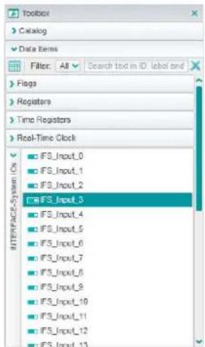
text_image
Toolbox Catalog Data Items Filter: All Search tool in ID: label and Flags Registers Time Registers Real-Time Clock IFS_Input_0 IFS_Input_1 IFS_Input_2 IFS_Input_3 IFS_Input_4 IFS_Input_5 IFS_Input_6 IFS_Input_7 IFS_Input_8 IFS_Input_9 IFS_Input_10 IFS_Input_11 IFS_Input_12 IFS_Input_13Figure 5-29 Interface system IOs
These Interface system IOs are used as 16-bit words. In order to read these 16-bit words as individual bits, the "IFSToFlags" and "FlagsToIFS" function blocks from the "INTERFACE System" library are required, which can be downloaded free of charge at phoenixcontact.net/products.
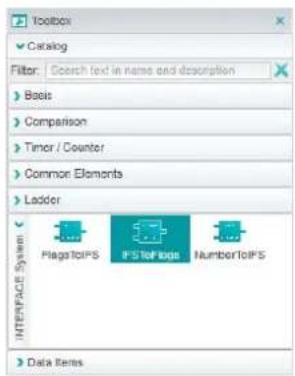
text_image
Toolbox Catalog Filter: Search text in name and description Basis Comparison Timer / Counter Common Elements Ladder INTERFACE System FlagToIPS IPS ToPage NumberToIPS Data ItemsFigure 5-30 Function blocks
The "IFSToFlags" function block can be used to break down an input word from the IFS gateway into its 16 bits.
The "FlagsToIFS" block combines the 16 individual bits into a 16-bit word that can be read by the IFS gateway.
Since LOGIC+ uses double integers (signed DINT, 32 bits) and the gateway uses integers (INT, 16 bits), you must watch out for an overrange or underrange of the value ranges.
Signed INT = -32,768 ... 32,767
Unsigned INT = 0 ... 65,535
You can use the "Check16Bit" function block for this.
An example program is shown in the screenshot below where input "IFS_Input_0" is broken down into its 16 bits and provided directly at the hardware outputs of the logic module + an extension module.
Furthermore, the values of the logic module realtime clock are forwarded to the gateway as numerical values.
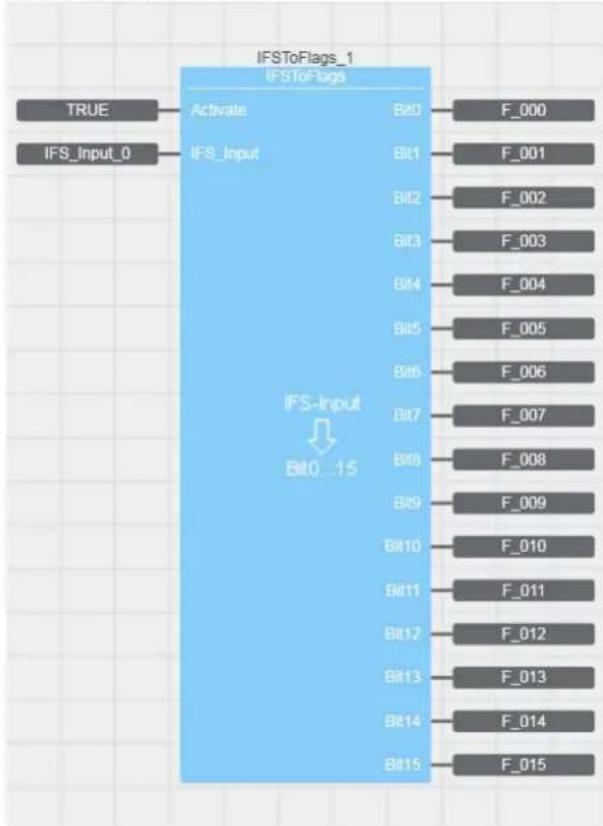
flowchart
graph TD
    A["IFS_Input_0"] --> B["IFS_Input"]
    C["IFSToFlags_1"] --> D["IFSToFlags"]
    B --> E["Bit0...15"]
    D --> F["F_000"]
    B --> G["Bit1"]
    B --> H["Bit2"]
    B --> I["Bit3"]
    B --> J["Bit4"]
    B --> K["Bit5"]
    B --> L["Bit6"]
    B --> M["Bit7"]
    B --> N["Bit8"]
    B --> O["Bit9"]
    B --> P["Bit10"]
    B --> Q["Bit11"]
    B --> R["Bit12"]
    B --> S["Bit13"]
    B --> T["Bit14"]
    B --> U["Bit15"]
Figure 5-31 Example program
5.8.5.2 Settings on the gateway

For the setting options for other gateways (Modbus/TCP, CANopen®, etc.), refer to application note "EM-XXX-GATEWAY-IFS", which is available as a download for the respective gateway at phoenixcontact.net/products.
The connection between the gateway and a PC is established using the IFS-USB-DATACA-BLE programming adapter (Order No. 2320500).
Insert the programming adapter into the S-PORT interface of the gateway. A USB connector is available on the PC side.
The IFS-CONF-SUITE-INTERFACE software is required in order to parameterize the gateway. It is available to download free of charge at phoenixcontact.net/products.
Install the following components:
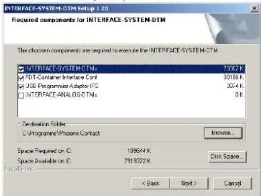
text_image
INTERFACE-SYSTEM-DTM Setup 1.20 Required components for INTERFACE-SYSTEM-DTM The chosen components are required to execute the INTERFACE-SYSTEM-DTM INTERFACE-SYSTEM-DTMs 73367 K FDT-Container Interface Cont 30186 K USB Programmer Adaptor IFS 3974 K INTERFACE-ANALOG-DTMs 0 K Destination Folder D:\Programme\Phoenix Contact Browse... Space Required on C: 109644 K. Space Available on C: 7919372 K Disk Space... Imported: < Back Next > CancelFigure 5-32 Installing components
Before parameterizing the required settings on the gateway, arrange the components as described in "Mounting" on page 87.
- Connect the T-BUS connection on the PLC-V8C logic module to the DIN rail connector using the appropriate PLC-V8C/CAB/TBUS/0,3M cable (Order No. 2905263).
- Establish the connection between the gateway and a PC using the IFS-USB-DATACA-BLE programming adapter (Order No. 2320500).
- Supply the gateway and the PLC logic module with the operating voltage (24 V DC, see technical data in the corresponding packing slip).
- Start the IFS-CONF program (FDT container) so that the gateway recognizes the Interface system IOs used.
- When IFS-CONF is started for the first time, you need to create a new user who is assigned the role of "Administrator". A password does not have to be assigned. You can create additional user names with different roles. (For example maintenance personnel, operating personnel or observers can be assigned different rights).

The user name is requested every time IFS-CONF is started. Keep a note of your user name.
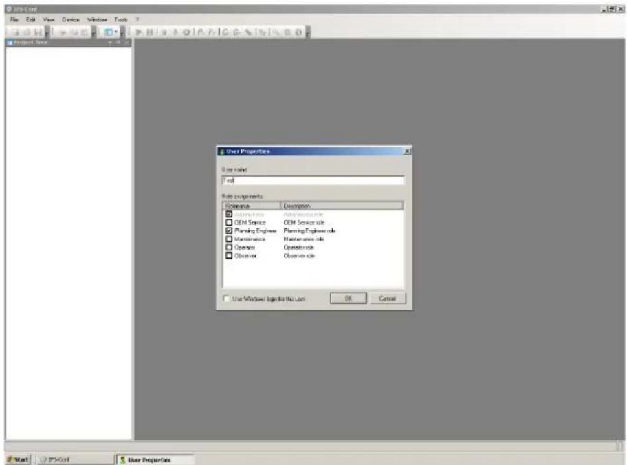
text_image
JPM-Conf File Edit View Device Window Tools Project Time User Properties User name: Test Code Assignment Description Description □ OEM Service OEM Service role □ OEM Service OEM Service role □ Planning Engineer Planning Engineer role □ Maintenance Maintenance role □ Operation Operator role □ Database Observation role □ Use Windows Sign For File User OK Cancel Start JPM-Conf User PropertiesFigure 5-33 User Properties > creating a user
- The installed device drivers for PLC logic are loaded in the next step.
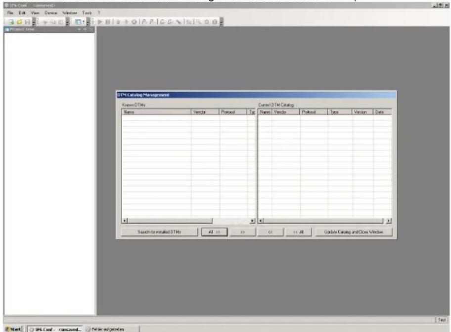
text_image
ITPC Catalog Management Items: ITPC Current ITPC Catalog Items: Vendor Protocol Top Name: Vendor Protocol Type Version Date Search for installed ITPs All 10 20 C++ All Update Catalog and Close Window Test Start: ITPC Conf - canceled... New optionsFigure 5-34 Loading device drivers
7. Click on the "Search for installed DTMs" button.

text_image
DTM Catalog Management File Edit View Device Window Tools Project Tools Name Vector Protocol Share Vector Protocol Type� Version Date DH MOBULS GATEWAY (IFG) F64 Phoenix Co.. IFSM, IFSM DH MOBULS GATEWAY (IFG)TCP Phoenix Co.. IFSM TCP L... DH PE GATEWAY (IFP)F01 Phoenix Co.. IFSM, IFSM DH PB GATEWAY (IFP)F02 Phoenix Co.. Positive DP... DH RS32 GATEWAY (IFS) Phoenix Co.. IFSM, IFSM DH RS45 GATEWAY (IFS) Phoenix Co.. IFSM, IFSM IFS TCP PREDADAPTER Phoenix Co.. IFSM TCP PSR 1000000000000000000000000000000000000000000000000000000000000000000000000000000000000000000000000000 HMO MOBULS 5 BURELLUP Phoenix Co.. IFSM HMO MOBULS 5 BURELLUP Phoenix Co.. IFSM HMIN MOB 2 PRT UR Phoenix Co.. IFSM HMIN MOB 2 PRT UR Phoenix Co.. IFSM HMIN MOB 2 TCU Phoenix Co.. IFSM HMIN MOB PRT UR Phoenix Co.. IFSM HMIN MOB TCU Phoenix Co.. IFSM HCP 1895C-NCDC-BM Phoenix Co.. IFSM PSR TRISAVE M Phoenix Co.. IFSM Search for installed DTMs All 12 13 14 15 All Update Catalog and Close Window Test Start: IPS-Cash - Cansaver... Prefer algorithmsFigure 5-35 Display of installed DTMs
- Select the EM-PB-GATEWAY-IFS(IFSM) gateway, the IFS-USB-PROG-ADAPTER programming adapter, and the PLC-V8C logic module.
- Add the selected devices to the current DTM catalog by clicking on the “>>” button.
- Click on the "Update Catalog and Close Window" button.
The program performs an automatic topology scan. The hardware structure is read.
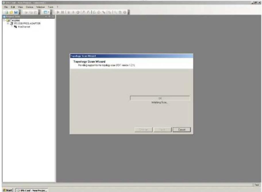
text_image
JPS-Card - New Project - NewProject File Edit View Device Window Tools Project Items Apache PC/USB/PROS ADAPTER FoxChannel Topology Scan Wizard Topology Scan Wizard Providing support to the topology scan (JDS version 1.21) OK Initiating from... Cancel Next JPS-Card - New Project...Figure 5-36 Topology scan
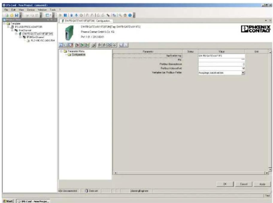
text_image
IPS-Conf - New Project - Composed File Edit View Devices Window Tools Project Type 1 template PS-USB/PDDR32 ADAPTER PinChannel ENPB-GATE/WAY/IPS/IPS/ITag ENPB-GATE/WAY/IFS IPSB/Gate/Dream/ PLC/WISC/INDIC/ISM ENPB-GATE/WAY/IPS/IPS/ITag ENPB-GATE/WAY/IFS Phoenix Contact GmbH & Co. KG Pin: 1.01 / 2012-09-01 PHOENIX CONTACT Parameters Menu Configuration Parameter Status Value Unit Application tag Pin Pinbase Subscription: 0 Pinbase Additional: 10 Translation be Pinbase False: Average Subscription OK Cancel Acute ADA Unconnected Data set Plascol Engineer Test Start IPS Conf - New Project...Figure 5-37 Hardware structure
- Double-click on the EM-PB-GATEWAY-IFS (IFSM) in the project tree.
This opens the gateway settings window.
- In the settings window, set the desired PROFIBUS address for the gateway under "PROFIBUS address offset".
- If you change the preset value, this information must be written to the gateway again. To do this, click on "Apply".
- You then need to connect to the gateway by clicking on "Connect" and write the new address to the gateway by clicking on "Write to device".
- Right-click on the EM-PB-GATEWAY-IFS in the project tree and select "Functions > Process value configuration".
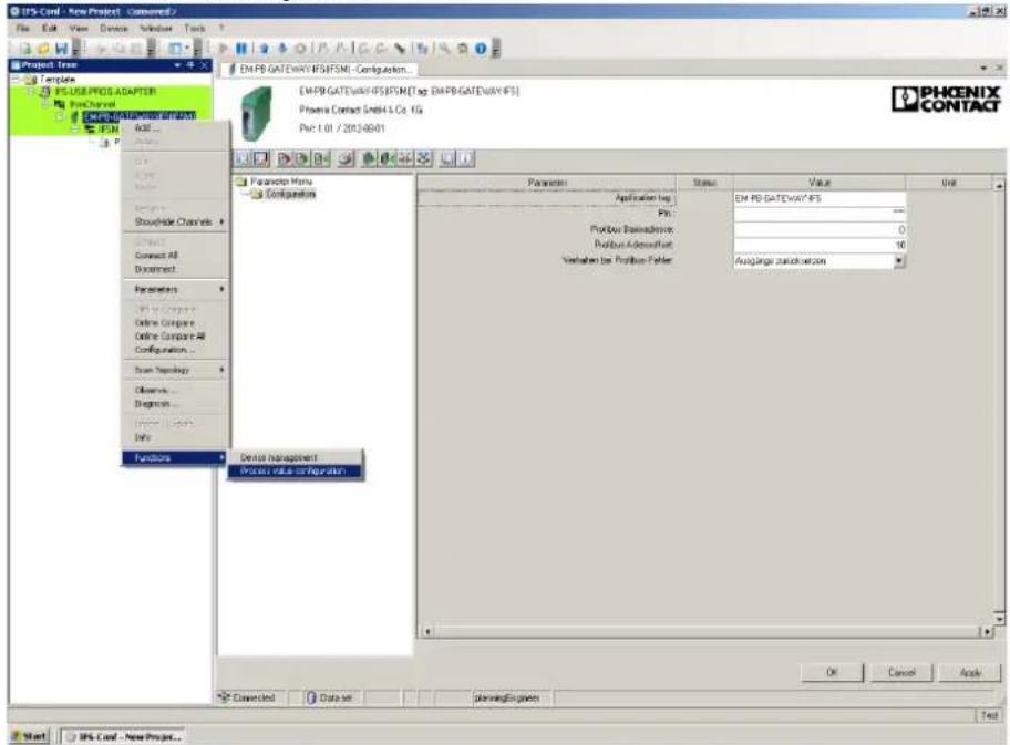
text_image
UFS-Conf - New Project - Connected File Edit View Device Window Tools Project Tree Template PSUSB PROS ADAPTER ProChannel EMPR-GATEWAY/IF5/PSMB [Tag: EMPR-GATEWAY/IF5] Phoenix Contact GmbH & Co. KG Pvt: 1.01 / 2014-08-01 PHCENIX CONTACT EMPR-GATEWAY/IF5/PSMB [Tag: EMPR-GATEWAY/IF5] Phoenix Contact GmbH & Co. KG Pvt: 1.01 / 2014-08-01 Parameters Menu Configuration Application log Pin: Portfolio Basadherence: Portfolio Addressfile: Variation by Portfolio-Fehler: EAuglange zuzukcawson Device management Process value configuration Parameters Status Value Unit Application log EH PD GATEWAY/IF5 - Portfolio Basadherence: 0 Portfolio Addressfile: 10 Variation by Portfolio-Fehler: EAuglange zuzukcawson Converted Data set planningEngine OK Cancel Acute Test UFS Conf - New Project...Figure 5-38 Opening the process data configuration
This is split into "Inputs" and "Outputs".
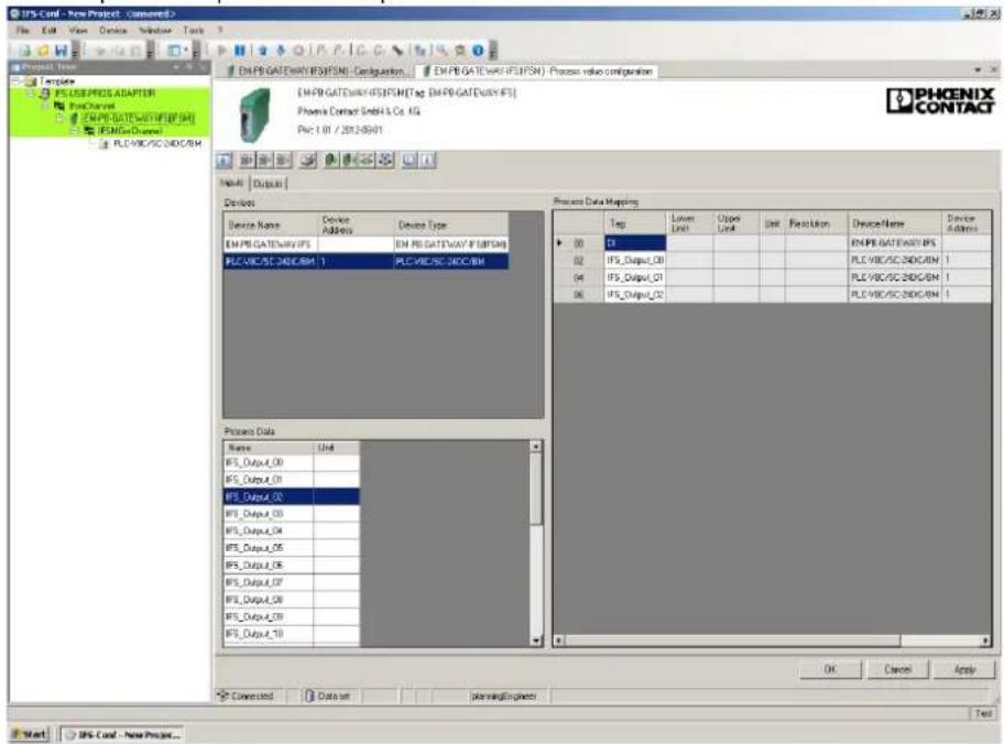
text_image
PHCENIX CONTACT PHCENIX Project Data Mapping Type: Unit BFS_Output_00 BFS_Output_01 BFS_Output_02 BFS_Output_03 BFS_Output_04 BFS_Output_05 BFS_Output_06 BFS_Output_07 BFS_Output_08 BFS_Output_09 BFS_Output_10 Input: Output Device Name Device Address Device Type EM.PB.GATEWAY/IFS/IFSN/Config. EM.PB.GATEWAY/IFS/IFSN/Process value configuration EM.PB.GATEWAY/IFS/IFSN/Tag EM.PB.GATEWAY/IFS Phoenix Contact GmbH 5 Co. KG Pack: 1.01 / 2012-05-01 OK Cancel Apply Connected Data set planningEngineer Test Start OIPS-Card - New Project...Figure 5-39 Process data configuration: inputs - outputs

Here, an output in LOGIC+ (e.g., IFS_Output_0) is an input for the gateway and can be found on the "Input" tab.
- Select "PLC-V8C...BM" in the "Devices" area.
Process data that can be selected is visible in the "Process Data" window (see also "Process data addressing" on page 103).
- Move the required process data to the "Process Data Mapping" window by means of drag and drop.
For example, "IFS_Output_00", "IFS_Output_01", and "IFS_Output_02" from the example program (see Figure 5-31 on page 92) for LOGIC+.
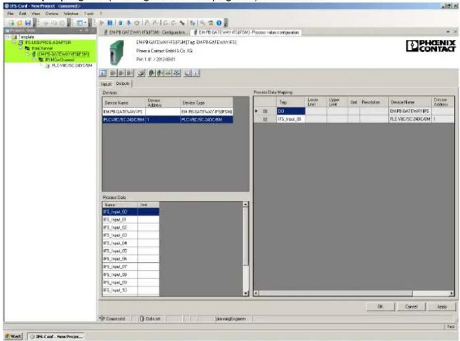
text_image
UFS-Conf - New Project - Connected File Edit View Device Window Tools ENPB GATEWAY IFS@FSN - Configurations ENPB GATEWAY IFS@FSN - Process value configuration ENPB GATEWAY IFS@FSN[Tag ENPB GATEWAY IFS] Phoenix Contact GmbH & Co. KG Pct: 1.01 / 20124801 PHCENIX CONTACT Input: Outputs Device Device Name Device Address Device Type EM.PB GATEWAY IFS EN PB GATEWAY IFS@FSN PLC/WBC/SC INDICAM 1 PLC/WBC/SC INDICAM Process Data Mapping Tag Lower Limit Upper Limit Unit Specification Device Name Device Address 00 CO 02 IFS_Input_01 ENPB GATEWAY IFS PLC/WBC/SC INDICAM 1 Process Data Name Unit IFS_Input_00 IFS_Input_01 IFS_Input_02 IFS_Input_03 IFS_Input_04 IFS_Input_05 IFS_Input_06 IFS_Input_07 IFS_Input_08 IFS_Input_09 IFS_Input_10 OK Cancel Apply Converted Data set ServerEngine Test UFS Conf - New Project...Figure 5-40 Process data configuration: example
-
Define the outputs in the process data assignment in the same way.
-
Apply the process data assignments by clicking on the "Apply" button in the active DTM project.
-
Click on the "Connect" button to establish a connection to the gateway.
-
Send the current configuration to the gateway by clicking on the "Write to device" button.
The values are now available in the gateway. They can be requested from the gateway via a PROFIBUS DP master.
5.8.5.3 Gateway communication with a PROFIBUS DP master
For additional settings, a connection must be established between the gateway and a PROFIBUS DP master (e.g., Siemens S7 controller) via a standard PROFIBUS cable.
A PROFIBUS interface is available on the gateway via a 9-pos. D-SUB connector (socket).

A Siemens S7-300 controller is shown in later screenshots.
A GSD file is required in order to integrate the gateway into the bus configuration. This is available to download at phoenixcontact.net/products.
After integrating the GSD in the STEP 7 catalog, the gateway can be found in the "PROFIBUS DP > Additional Field Devices > Gateway" area. The "EM-PB-GATEWAY-IFS" must now be inserted in the PROFIBUS bus configuration.
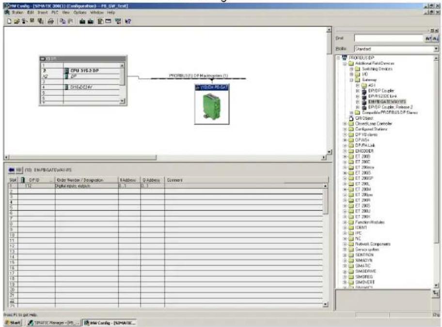
text_image
OPROM 316.2 DP PROVBUS DP Hysteresian (T) 1000M PESAT (10) EMPIGATE/AVSYS SVM DP ID Order Number / Designation Address D Address Current 1 112 Digital ports output 0, 1 0, 1 2 3 4 5 6 7 8 9 10 11 12 13 14 15 16 17 18 19 20 21 22 23 24 25 26 27 28 29 30 31 32 33 34 35 36 37 38 39 40 41 42 43 44 45 46 47 48 49 50 51 52 53 54 55 56 57 58 59 60 61 62 63 64 65 66 67 68 69 70 71 72 73 74 75 76 77 78 79 80 81 82 83 84 85 86 87 88 89 90 91 92 93 94 95 96 97 98 99 100Figure 5-41 Inserting the gateway in the bus configuration
- Open the properties window by double-clicking on the gateway in the bus configuration.
- On the "Parameter Assignment" tab, set the "Configuration via DTM" entry to "Enabled" and the "Byte order" to "Intel".

flowchart
graph TD
    A["CPU ICS-2 DP"] --> B["PROBUS IP (DP-Management)"]
    B --> C["Properties - DP class"]
    C --> D["General Parameters Assignment"]
    D --> E["Parameters"]
    E --> F["PROBUS IP"]
    F --> G["Output"]
    G --> H["PROBUS DP"]
    H --> I["Output"]
    style A fill:#f9f,stroke:#333
    style B fill:#ccf,stroke:#333
    style C fill:#cfc,stroke:#333
    style D fill:#fcc,stroke:#333
Figure 5-42 Setting the "Configuration via DTM" and "Byte order" entries
- Open the EM-PB-GATEWAY-IFS in the catalog. The possible process words are listed.

"Byte order" sets the byte order of the transferred data.
- Motorola: Big Endian (the high byte is saved first)
- Intel: Little Endian (the low byte is saved first)
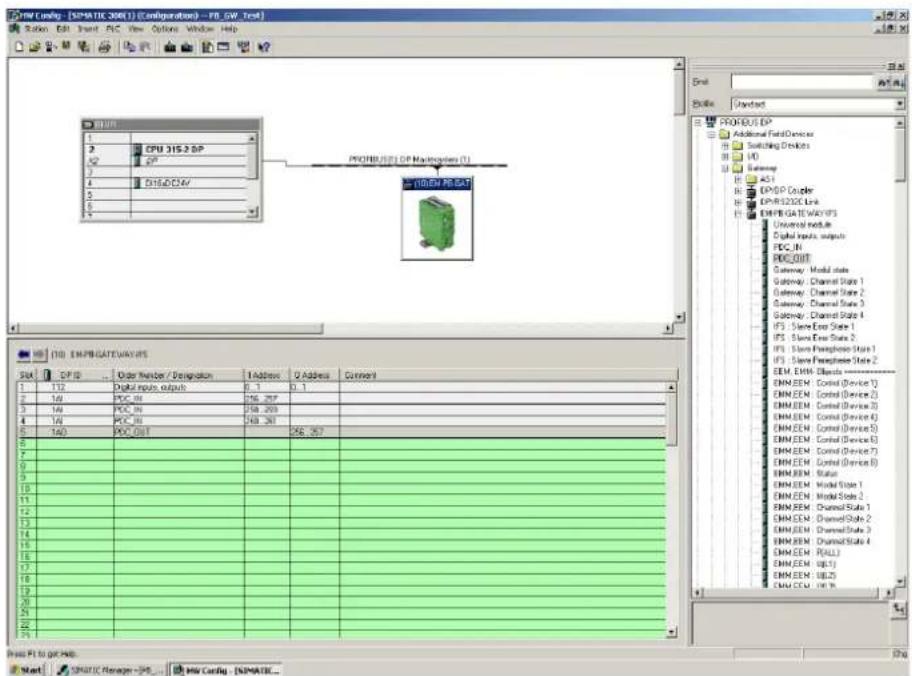
text_image
PROBUS DP Additional Field Devices Switching Devices Gateway Gateway Gateway Gateway Gateway Gateway Gateway Gateway Gateway Gateway Gateway Gateway Gateway Gateway Gateway Gateway Gateway Gateway Gateway Gateway Gateway Gateway Gateway Gateway Gateway Gateway Gateway Gateway Gateway Gateway Gateway Gateway Gateway Gateway Gateway Gateway Gateway Gateway Gateway Gateway Gateway Gateway Gateway Gateway Gateway Gateway Gateway Gateway Gateway Gateway Portfolio System1 Portfolio System2 Portfolio System3 Portfolio System4 Portfolio System5 Portfolio System6 Portfolio System7 Portfolio System8 Portfolio System9 Portfolio System10 Portfolio System11 Portfolio System12 Portfolio System13 Portfolio System14 Portfolio System15 Portfolio System16 Portfolio System17 Portfolio System18 Portfolio System19 Portfolio System20 Portfolio System21 Portfolio System22 Portfolio System23 Portfolio System24 Portfolio System25 Portfolio System26 Portfolio System27 Portfolio System28 Portfolio System29 Portfolio System30 Portfolio System31 Portfolio System32 Portfolio System33 Portfolio System34 Portfolio System35 Portfolio System36 Portfolio System37 Portfolio System38 Portfolio System39 Portfolio System40 Portfolio System41 Portfolio System42 Portfolio System43 Portfolio System44 Portfolio System45 Portfolio System46 Portfolio System47 Portfolio System48 Portfolio System49 Portfolio System50 Portfolio System51 Portfolio System52 Portfolio System53 Portfolio System54 Portfolio System55 Portfolio System56 Portfolio System57 Portfolio System58 Portfolio System59 Portfolio System60 Portfolio System61 Portfolio System62 Portfolio System63 Portfolio System64 Portfolio System65 Portfolio System66 Portfolio System67 Portfolio System68 Portfolio System69 Portfolio System70 Portfolio System71 Portfolio System72 Portfolio System73 Portfolio System74 Portfolio System75 Portfolio System76 Portfolio System77 Portfolio System78 Portfolio System79 Portfolio System80Figure 5-43 Listing process words
- For PLC logic, use "PDC_IN" (input from DTM) and "PDC_OUT" (output from DTM) from the catalog.
| Address | Tag | Lower Limit | Upper Limit | Unit | Resolution | Device Name | |
| 00 | DI | EM PB GATEWAY IFS | |||||
| 02 | IFS_Output_00 | PLC V8C/SC-24DC/BM | |||||
| 04 | IFS_Output_01 | PLC V8C/SC-24DC/BM | |||||
| 06 | IFS_Output_02 | PLC V8C/SC-24DC/BM | |||||
| Address | Tag | Lower Limit | Upper Limit | Unit | Resolution | Device Name | |
| 00 | DO | EM PB GATEWAY IFS | |||||
| 02 | IFS_Input_00 | PLC V8C/SC-24DC/BM | |||||
| Skt | DP ID | Order Number / Designation | I Address | Q Address | |||
| 1 | 112 | Digital inputs, outputs | 0...1 | 0...1 | |||
| 2 | 1AI | PDC_IN | 256...257 | ||||
| 3 | 1AI | PDC_IN | 258...259 | ||||
| 4 | 1AI | PDC_IN | 260...261 | ||||
| 5 | 1AO | PDC_OUT | 256...257 | ||||
Figure 5-44 "PDC_IN" (input from DTM) and "PDC_OUT" (output from DTM)
The order of the inputs and outputs must be the same as the process data assignment in the DTM.
Input and output addresses are assigned automatically by STEP 7 when added. They can now be used in the program code.
5.9 Communication via Modbus/RTU
Using the IFS-RS232-DATACABLE RS-232 connecting cable (Order No. 2320490),
PLC logic (acting as a Modbus slave) can communicate with a Modbus master.
To do this, insert the connecting cable into the Memory socket for the memory module.
PLC logic is assigned slave ID 192.
Connection settings of the serial port:
- 115,200 baud
- 8 data bits
- E v e n p a r i t y
- 1 stop bit
5.9.1 Process data addressing
Table 5-13 Status of the basic module
| Name Address Bit Description | ||||
| BM_STATE | 7420 | 29728 | 0 Device status0: system in STOP state or not configured1: system in RUN state | |
| 1 | Communication status0: no data traffic to the gateway1: cyclic data traffic to the gateway | |||
| 2 | Internal error | |||
| 3 | External error | |||
| 4 | Reserved | |||
| 5 | Reserved | |||
| 6 | Reserved | |||
| 7 | Reserved | |||
| 8 | Error at extension module 1 | |||
| 9 | Error at extension module 2 | |||
| 10 | Reserved | |||
| 11 | Reserved | |||
| 12 | Reserved | |||
| 13 | Reserved | |||
| 14 | Reserved | |||
| 15 | Reserved | |||
Table 5-14 Digital inputs/outputs of the basic module
| Name Address | Bit Description | |||
| Hex Bin | ||||
| BM_IN_OUT 7421 29729 0 Input IN0 | (DI_0_0) | |||
| 1 Input | IN1 (DI_0_1) | |||
| 2 Input | IN2 (DI_0_2) | |||
| 3 Input | IN3 (DI_0_3) | |||
| 4 Input | IN4 (DI_0_4) | |||
| 5 Input | IN5 (DI_0_5) | |||
| 6 Input | IN6 (DI_0_6) | |||
| 7 Input | IN7 (DI_0_7) | |||
| 8 Input | /output 8 (DI_0_8 / DQ_0_8) | |||
| 9 Input | /output 9 (DI_0_9 / DQ_0_9) | |||
| 10 Input | /output 10 (DI_0_10 / DQ_0_10) | |||
| 11 Input | /output 11 (DI_0_11 / DQ_0_11) | |||
| 12 Input | /output 12 (DI_0_12 / DQ_0_12) | |||
| 13 Input | /output 13 (DI_0_13 / DQ_0_13) | |||
| 14 Input | /output 14 (DI_0_14 / DQ_0_14) | |||
| 15 Input | /output 15 (DI_0_15 / DQ_0_15) | |||
Table 5-15 Analog inputs/outputs of the basic module
| Name Address Bit | Description | |||
| Hex Bin | ||||
| BM_ANALOG_6 74 | 22 29730 | - Analog | input value IN6 (AI_0_6) | |
| BM_ANALOG_7 74 | 23 29731 | - Analog | input value IN7 (AI_0_7) | |
| BM_ANALOG_8 74 | 2C 29740 | - Analog | input/output 8 (AI_0_8 / AO_0_8) | |
| BM_ANALOG_9 74 | 2D 29741 | - Analog | input/output 9 (AI_0_9 / AO_0_9) | |
| BM_ANALOG_10 74 | 42E 29742 | - Analog | input/output 10 (AI_0_10 / AO_0_10) | |
| BM_ANALOG_11 74 | 42F 29743 | - Analog | input/output 11 (AI_0_11 / AO_0_11) | |
| BM_ANALOG_12 74 | 430 29744 | - Analog | input/output 12 (AI_0_12 / AO_0_12) | |
| BM_ANALOG_13 74 | 431 29745 | - Analog | input/output 13 (AI_0_13 / AO_0_13) | |
| BM_ANALOG_14 74 | 432 29746 | - Analog | input/output 14 (AI_0_14 / AO_0_14) | |
| BM_ANALOG_15 74 | 433 29747 | - Analog | input/output 15 (AI_0_15 / AO_0_15) | |
Table 5-16 Status of extension module 1
| Name | Address | Bit | Description | |
| Hex | Bin | |||
| EM_1_STATUS | 7424 | 29732 0 | Reserved | |
| 1 | Reserved | |||
| 2 | Internal error | |||
| 3 | External error | |||
| 4 | Reserved | |||
| 5 | Reserved | |||
| 6 | Reserved | |||
| 7 | Reserved | |||
| 8 | Reserved | |||
| 9 | Reserved | |||
| 10 | Reserved | |||
| 11 | Reserved | |||
| 12 | Reserved | |||
| 13 | Reserved | |||
| 14 | Reserved | |||
| 15 | Reserved | |||
Table 5-17 Inputs/outputs of extension module 1
| Name Address Bit Description | ||||
| EM_2_STATUS 7428 29736 0 Reserved | ||||
| 1 Reserved | ||||
| 2 Internal error | ||||
| 3 External error | ||||
| 4 Reserved | ||||
| 5 Reserved | ||||
| 6 Reserved | ||||
| 7 Reserved | ||||
| 8 Reserved | ||||
| 9 Reserved | ||||
| 10 Reserved | ||||
| 11 Reserved | ||||
| 12 Reserved | ||||
| 13 Reserved | ||||
| 14 Reserved | ||||
| 15 Reserved | ||||
Table 5-20 Digital inputs/outputs of extension module 2
Table 5-22 Realtime clock
| Name Address Bit | Description | |||
| Hex Bin | ||||
| RTC_SEC 7700 30464 - Realtime clock seconds | ||||
| RTC_MIN 7702 30466 - Realtime clock minutes | ||||
| RTC_HOUR 7704 30468 - Realtime clock hours | ||||
| RTC_DOM 7706 30470 - Realtime clock day of the month | ||||
| RTC_DOW 7708 30472 - Realtime clock day of the week | ||||
| RTC_DOY | 770A | 30474 - Realtime clock day of the year | ||
| RTC_MONTH 770C | 30476 - Realtime clock month | |||
| RTC_YEAR | 770E | 30478 - Realtime clock year | ||
| RTC_DaylightSavingTime | 7712 30482 - Daylight saving time | |||
Table 5-23 Flags 000 ... 015
| Name | Address | Bit | Description | |
| Hex Bin | ||||
| F_000 ... F_015 | 75D0 | 30160 | 0 | Flag F_000 |
| 1 | Flag F_001 | |||
| 2 | Flag F_002 | |||
| 3 | Flag F_003 | |||
| 4 | Flag F_004 | |||
| 5 | Flag F_005 | |||
| 6 | Flag F_006 | |||
| 7 | Flag F_007 | |||
| 8 | Flag F_008 | |||
| 9 | Flag F_009 | |||
| 10 | Flag F_010 | |||
| 11 | Flag F_011 | |||
| 12 | Flag F_012 | |||
| 13 | Flag F_013 | |||
| 14 | Flag F_014 | |||
| 15 | Flag F_015 | |||
Table 5-24 Flags 016 ... 031
| Name Address Bit | Description | |||
| Hex Bin | ||||
| F_016 ... F_031 75D | 2 30162 0 Flag | F_016 | ||
| 1 | F I | |||
| 2 | F I | |||
| 3 | F I | |||
| 4 | F I | |||
| 5 | F I | |||
| 6 | F I | |||
| 7 | F I | |||
| 8 | F I | |||
| 9 | F I | |||
| 10 Flag F_026 | ||||
| 11 Flag F_027 | ||||
| 12 Flag F_028 | ||||
| 13 Flag F_029 | ||||
| 14 Flag F_030 | ||||
| 15 Flag F_031 | ||||
Table 5-25 Flags 032 ... 047
| Name Address Bit Description | ||||
| F_032 ... F_047 75D4 | 30164 0 Flag | F_032 | ||
| 1 Flag F_033 | ||||
| 2 Flag F_034 | ||||
| 3 Flag F_035 | ||||
| 4 Flag F_036 | ||||
| 5 Flag F_037 | ||||
| 6 Flag F_038 | ||||
| 7 Flag F_039 | ||||
| 8 Flag F_040 | ||||
| 9 Flag F_041 | ||||
| 10 Flag F_042 | ||||
| 11 Flag F_043 | ||||
| 12 Flag F_044 | ||||
| 13 Flag F_045 | ||||
| 14 Flag F_046 | ||||
| 15 Flag F_047 | ||||
Table 5-26 Flags 048 ... 063
| Name Address Bit Description | ||||
| Hex Bin | ||||
| F_048 ... F_063 75D6 30166 0 Flag | F_048 | |||
| 1 | F I a | |||
| 2 | F I a | |||
| 3 | F I a | |||
| 4 | F I a | |||
| 5 | F I a | |||
| 6 | F I a | |||
| 7 | F I a | |||
| 8 | F I a | |||
| 9 | F I a | |||
| 10 Flag F_058 | ||||
| 11 Flag F_059 | ||||
| 12 Flag F_060 | ||||
| 13 Flag F_061 | ||||
| 14 Flag F_062 | ||||
| 15 Flag F_063 | ||||
Table 5-27 Flags 064 ... 079
| Name Address Bit Description | ||||
| F_064 ... F_079 75D8 | 30168 0 Flag | F_064 | ||
| 1 Flag F_065 | ||||
| 2 Flag F_066 | ||||
| 3 Flag F_067 | ||||
| 4 Flag F_068 | ||||
| 5 Flag F_069 | ||||
| 6 Flag F_070 | ||||
| 7 Flag F_071 | ||||
| 8 Flag F_072 | ||||
| 9 Flag F_073 | ||||
| 10 Flag F_074 | ||||
| 11 Flag F_075 | ||||
| 12 Flag F_076 | ||||
| 13 Flag F_077 | ||||
| 14 Flag F_078 | ||||
| 15 Flag F_079 | ||||
Table 5-28 Flags 080 ... 095
| Name Address Bit Description | ||||
| F_080 ... F_095 75DA 30170 0 Flag | F_080 | |||
| 1 Flag F_081 | ||||
| 2 Flag F_082 | ||||
| 3 Flag F_083 | ||||
| 4 Flag F_084 | ||||
| 5 Flag F_085 | ||||
| 6 Flag F_086 | ||||
| 7 Flag F_087 | ||||
| 8 Flag F_088 | ||||
| 9 Flag F_089 | ||||
| 10 Flag F_090 | ||||
| 11 Flag F_091 | ||||
| 12 Flag F_092 | ||||
| 13 Flag F_093 | ||||
| 14 Flag F_094 | ||||
| 15 Flag F_095 | ||||
Table 5-29 Flags 096 ... 111
| Name Address Bit Description | ||||
| F_096 ... F_111 75DC 30172 0 Flag F_096 | ||||
| 1 Flag F_097 | ||||
| 2 Flag F_098 | ||||
| 3 Flag F_099 | ||||
| 4 Flag F_100 | ||||
| 5 Flag F_101 | ||||
| 6 Flag F_102 | ||||
| 7 Flag F_103 | ||||
| 8 Flag F_104 | ||||
| 9 Flag F_105 | ||||
| 10 Flag F_106 | ||||
| 11 Flag F_107 | ||||
| 12 Flag F_108 | ||||
| 13 Flag F_109 | ||||
| 14 Flag F_110 | ||||
| 15 Flag F_111 | ||||
Table 5-30 Flags 112 ... 127
| Name Address Bit Description | ||||
| F_112 ... F_127 75DE 30174 0 Flag | F_112 | |||
| 1 Flag F_113 | ||||
| 2 Flag F_114 | ||||
| 3 Flag F_115 | ||||
| 4 Flag F_116 | ||||
| 5 Flag F_117 | ||||
| 6 Flag F_118 | ||||
| 7 Flag F_119 | ||||
| 8 Flag F_120 | ||||
| 9 Flag F_121 | ||||
| 10 Flag F_122 | ||||
| 11 Flag F_123 | ||||
| 12 Flag F_124 | ||||
| 13 Flag F_125 | ||||
| 14 Flag F_126 | ||||
| 15 Flag F_127 | ||||
Table 5-31 Time registers 000 ... 015
| Name Address Bit D | Description | |||
| Hex Bin | ||||
| T_000 75B0 30128 - | Time register | T_000 | ||
| T_001 75B2 30130 - | Time register | T_001 | ||
| T_002 75B4 30132 - | Time register | T_002 | ||
| T_003 75B6 30134 - | Time register | T_003 | ||
| T_004 75B8 30136 - | Time register | T_004 | ||
| T_005 75BA 30138 - | Time register | T_005 | ||
| T_006 75BC 30140 - | Time register | T_006 | ||
| T_007 75BE 30142 - | Time register | T_007 | ||
| T_008 75C0 30144 - | Time register | T_008 | ||
| T_009 75C2 30146 - | Time register | T_009 | ||
| T_010 75C4 30148 - | Time register | T_010 | ||
| T_011 75C6 30150 - | Time register | T_011 | ||
| T_012 75C8 30152 - | Time register | T_012 | ||
| T_013 75CA 30154 - | Time register | T_013 | ||
| T_014 75CC | 30156 - Time | register T_014 | ||
| T_015 75CE 30158 - | Time register | T_015 | ||
Table 5-32 Registers 000 ... 023
| Name Address | Bit Description | |||
| Hex Bin | ||||
| R_000 7580 300 | 080 - Register R_ | 000 | ||
| R_001 7582 300 | 082 - Register R_ | 001 | ||
| R_002 7584 300 | 084 - Register R_ | 002 | ||
| R_003 7586 300 | 086 - Register R_ | 003 | ||
| R_004 7588 300 | 088 - Register R_ | 004 | ||
| R_005 758A 300 | 090 - Register R_ | 005 | ||
| R_006 758C 300 | 092 - Register R_ | 006 | ||
| R_007 758E 300 | 094 - Register R_ | 007 | ||
| R_008 7590 300 | 096 - Register R_ | 008 | ||
| R_009 7592 300 | 098 - Register R_ | 009 | ||
| R_010 7594 301 | 100 - Register R_ | 010 | ||
| R_011 7596 301 | 102 - Register R_ | 011 | ||
| R_012 7598 301 | 104 - Register R_ | 012 | ||
| R_013 759A 301 | 106 - Register R_ | 013 | ||
| R_014 759C 301 | 108 - Register R_ | 014 | ||
| R_015 759E 301 | 110 - Register R_ | 015 | ||
| R_016 75A0 301 | 112 - Register R_ | 016 | ||
| R_017 75A2 301 | 114 - Register R_ | 017 | ||
| R_018 75A4 301 | 116 - Register R_ | 018 | ||
| R_019 75A6 301 | 118 - Register R_ | 019 | ||
| R_020 75A8 301 | 120 - Register R_ | 020 | ||
| R_021 75AA 301 | 122 - Register R_ | 021 | ||
| R_022 75AC 301 | 124 - Register R_ | 022 | ||
| R_023 75AE 301 | 126 - Register R_ | 023 | ||
Table 5-33 INTERFACE system input 0 ... 15
| Name Address | Bit Description | |||
| Hex Bin | ||||
| IFS_Input_0 7400 | 29696 - INTERFACE system input 0 | |||
| IFS_Input_1 7401 | 29697 - INTERFACE system input 1 | |||
| IFS_Input_2 7402 | 29698 - INTERFACE system input 2 | |||
| IFS_Input_3 7403 | 29699 - INTERFACE system input 3 | |||
| IFS_Input_4 7404 | 29700 - INTERFACE system input 4 | |||
| IFS_Input_5 7405 | 29701 - INTERFACE system input 5 | |||
| IFS_Input_6 7406 | 29702 - INTERFACE system input 6 | |||
| IFS_Input_7 7407 | 29703 - INTERFACE system input 7 | |||
| IFS_Input_8 7408 | 29704 - INTERFACE system input 8 | |||
| IFS_Input_9 7409 | 29705 - INTERFACE system input 9 | |||
| IFS_Input_10 740A | 29706 - INTERFACE system input 10 | |||
| IFS_Input_11 740B | 29707 - INTERFACE system input 11 | |||
| IFS_Input_12 740C | 29708 - INTERFACE system input 12 | |||
| IFS_Input_13 740D | 29709 - INTERFACE system input 13 | |||
| IFS_Input_14 740E | 29710 - INTERFACE system input 14 | |||
| IFS_Input_15 740F | 29711 - INTERFACE system input 15 | |||
Table 5-34 INTERFACE system output 0 ... 15
| Name Address Bit | Description | |||
| Hex Bin | ||||
| IFS_Output_0 7410 | 29712 - INT | ERFACE system output 0 | ||
| IFS_Output_1 7411 | 29713 - INT | ERFACE system output 1 | ||
| IFS_Output_2 7412 | 29714 - INT | ERFACE system output 2 | ||
| IFS_Output_3 7413 | 29715 - INT | ERFACE system output 3 | ||
| IFS_Output_4 7414 | 29716 - INT | ERFACE system output 4 | ||
| IFS_Output_5 7415 | 29717 - INT | ERFACE system output 5 | ||
| IFS_Output_6 7416 | 29718 - INT | ERFACE system output 6 | ||
| IFS_Output_7 7417 | 29719 - INT | ERFACE system output 7 | ||
| IFS_Output_8 7418 | 29720 - INT | ERFACE system output 8 | ||
| IFS_Output_9 7419 | 29721 - INT | ERFACE system output 9 | ||
| IFS_Output_10 741A | 29722 - IN | TERFACE system output 10 | ||
| IFS_Output_11 741B | 29723 - IN | TERFACE system output 11 | ||
| IFS_Output_12 741C | 29724 - IN | TERFACE system output 12 | ||
| IFS_Output_13 741D | 29725 - IN | TERFACE system output 13 | ||
| IFS_Output_14 741E | 29726 - IN | TERFACE system output 14 | ||
| IFS_Output_15 741F | 29727 - IN | TERFACE system output 15 | ||
6 Function examples

In this section, the software programming environment is illustrated with the aid of a few examples. The examples are intended to assist the user, however the user is still responsible for checking the respective programming, in particular with regard to its suitability in specific applications. It is your responsibility as the user to conduct a risk and functional analysis of the relevant program logic in relation to current standards and to assess the validity of these for your activities. The analysis should extend to the system in which the logic modules are to be used. An overall validation and regression testing must be carried out in particular.
The program examples are solely for explanation purposes and do not claim to be complete. They must therefore not be generalized or used without being checked.
Please observe the notes provided in the packing slip for the logic module and in the software, especially any safety notes and installation instructions.
6.1 Analog differential threshold value switch
The output is switched on and off according to a parameterizable threshold and differential value.
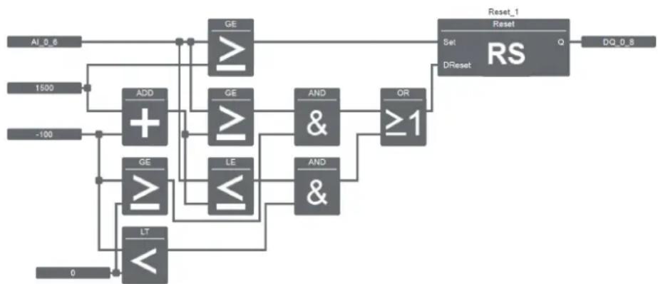
flowchart
graph TD
    A["AL_0.6"] --> B["ADD"]
    C["1500"] --> B
    D["-100"] --> E["GE"]
    D --> F["LE"]
    D --> G["LT"]
    H["0"] --> I["LT"]
    B --> J["GE"]
    E --> K["GE"]
    F --> L["GE"]
    G --> M["GE"]
    J --> N["AND &"]
    K --> O["AND &"]
    L --> P["AND &"]
    M --> Q["OR ≥1"]
    N --> R["Set DReset"]
    O --> R
    P --> S["Reset_1 Reset"]
    Q --> S
    R --> T["RS"]
    S --> U["DQ_0.8"]
Figure 6-1 Analog differential threshold value switch code
6.2 Analog threshold value switch
The output is switched on and off according to two parameterizable threshold values (hysteresis).
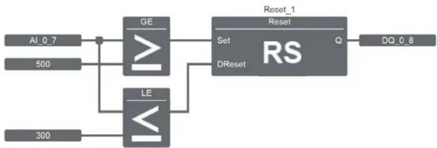
flowchart
graph TD
    A["AI_0_7"] --> B["GE"]
    C["500"] --> B
    D["300"] --> E["LE"]
    B --> F["Set"]
    E --> G["RS"]
    F --> H["DReset"]
    G --> I["Reset_1"]
    I --> J["DQ_0_8"]
Figure 6-2 Analog threshold value switch code
6.3 Analog comparator
The output is switched on and off according to the difference between Ax - Ay and two parameterizable threshold values.
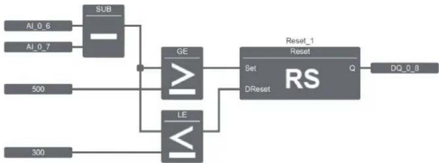
flowchart
graph TD
    A["AI_0_6"] --> B["SUB"]
    C["AI_0_7"] --> B
    B --> D["GE"]
    E["500"] --> D
    F["300"] --> G["LE"]
    D --> H["Set"]
    G --> I["DReset"]
    H --> J["RS"]
    I --> J
    J --> K["DQ_0_8"]
    style B fill:#999
    style D fill:#999
    style G fill:#999
    style H fill:#ccc
    style I fill:#ccc
    style J fill:#ccc
    style K fill:#ccc
Figure 6-3 Analog comparator code
6.4 Pulse relay
The output is switched on or off by an input pulse.
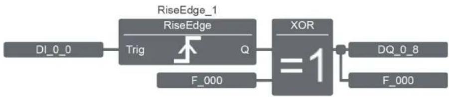
flowchart
graph LR
    A["DI_0_0"] --> B["RiseEdge"]
    B --> C["Trig"]
    C --> D["F_000"]
    D --> E["XOR"]
    E --> F["DQ_0_8"]
    E --> G["F_000"]
    style B fill:#f9f,stroke:#333
    style E fill:#ccf,stroke:#333
Figure 6-4 Pulse relay code
6.5 Interval time-delay relay with pulse output
An input signal switches the output to the TRUE state. The output is reset after a parameterizable time or after the input changes from FALSE to TRUE.
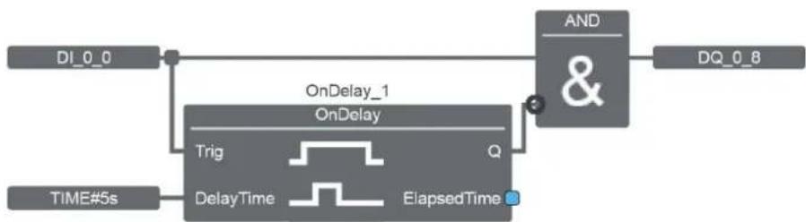
flowchart
graph LR
    DI_0_0 --> ONDelay_1["OnDelay"]
    ONDelay_1 --> AND["AND &"]
    ONDelay_1 --> DQ_0_8
    ONDelay_1 --> Trig["Trig"]
    Trig --> DelayTime["DelayTime"]
    DelayTime --> ElapsedTime["ElapsedTime"]
    TIME#5s --> ONDelay_1
Figure 6-5 Interval time-delay relay with pulse output code
6.6 Edge-triggered interval time-delay relay
An input pulse generates a number of signals at the output after an adjustable time (can be retriggered).
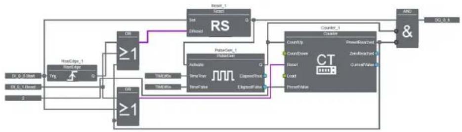
flowchart
graph TD
    A["Input"] --> B["TRig"]
    B --> C["FreeCase_1"]
    C --> D[">=1"]
    D --> E["RS"]
    E --> F["Reset_1"]
    F --> G["Offset"]
    G --> H["RS"]
    H --> I["0"]
    I --> J["Pulsor_1"]
    J --> K["Active"]
    J --> L["Send/Write"]
    J --> M["Expense/Read"]
    J --> N["Expense/False"]
    K --> O["Counter_1"]
    L --> O
    M --> O
    N --> O
    O --> P["AND &"]
    P --> Q["SQ 0.8"]
    R["TRig"] --> S[">=1"]
    S --> T["TSUR/IPS"]
    T --> U["TIME/IPS"]
    U --> V["TRIG/IPS"]
    V --> W["TSUR/IPS"]
    W --> X["TRIG/IPS"]
    X --> Y["TSUR/IPS"]
    Y --> Z["TRIG/IPS"]
    Z --> AA["TSUR/IPS"]
    AA --> AB["TRIG/IPS"]
    AB --> AC["TSUR/IPS"]
    AC --> AD["TRIG/IPS"]
    AD --> AE["TSUR/IPS"]
    AE --> AF["TRIG/IPS"]
    AF --> AG["TSUR/IPS"]
    AG --> AH["TRIG/IPS"]
    AH --> AI["TSUR/IPS"]
    AI --> AJ["TRIG/IPS"]
    AJ --> AK["TSUR/IPS"]
    AK --> AL["TRIG/IPS"]
    AL --> AM["TSUR/IPS"]
    AM --> AN["TRIG/IPS"]
    AN --> AO["TSUR/IPS"]
    AO --> AP["TRIG/IPS"]
    AP --> AQ["TSUR/IPS"]
    AQ --> AR["TRIG/IPS"]
    AR --> AS["TSUR/IPS"]
    AS --> AT["TRIG/IPS"]
    AT --> AU["TSUR/IPS"]
    AU --> AV["TRIG/IPS"]
    AV --> AW["TSUR/IPS"]
    AW --> AX["TRIG/IPS"]
    AX --> AY["TSUR/IPS"]
    AY --> AZ["TRIG/IPS"]
    AZ --> BA["TSUR/IPS"]
    BA --> BB["TRIG/IPS"]
    BB --> BC["TSUR/IPS"]
    BC --> BD["TRIG/IPS"]
    BD --> BE["TSUR/IPS"]
    BE --> BF["TRIG/IPS"]
    BF --> BG["TSUR/IPS"]
    BG --> BH["TRIG/IPS"]
    BH --> BI["TSUR/IPS"]
    BI --> BJ["TRIG/IPS"]
    BJ --> BK["TSUR/IPS"]
    BK --> BL["TRIG/IPS"]
    BL --> BM["TSUR/IPS"]
    BM --> BN["TRIG/IPS"]
    BN --> BO["TSUR/IPS"]
    BO --> BP["TRIG/IPS"]
    BP --> BQ["TSUR/IPS"]
    BQ --> BR["TRIG/IPS"]
    BR --> BS["TSUR/IPS"]
    BS --> BT["TRIG/IPS"]
    BT --> BU["TSUR/IPS"]
    BU --> BV["TRIG/IPS"]
    BV --> BW["TSUR/IPS"]
    BW --> BX["TRIG/IPS"]
    BX --> BY["TSUR/IPS"]
    BY --> BZ["TRIG/IPS"]
    BZ --> CA["TSUR/IPS"]
    CA --> CB["TRIG/IPS"]
    CB --> CC["TSUR/IPS"]
    CC --> CD["TRIG/IPS"]
    CD --> CE["TSUR/IPS"]
    CE --> CF["TRIG/IPS"]
    CF --> CG["TSUR/IPS"]
    CG --> CH["TRIG/IPS"]
    CH --> CI["TSUR/IPS"]
    CI --> CJ["TRIG/IPS"]
    CJ --> CK["TSUR/IPS"]
    CK --> CL["TRIG/IPS"]
    CL --> CM["TSUR/IPS"]
    CM --> CN["TRIG/IPS"]
    CN --> CO["TSUR/IPS"]
    CO --> CP["TRIG/IPS"]
    CP --> CQ["TSUR/IPS"]
    CQ --> CR["TRIG/IPS"]
    CR --> CS["TSUR/IPS"]
    CS --> CT["TRIG/IPS"]
    CT --> CU["TSUR/IPS"]
    CU --> CV["TRIG/IPS"]
    CV --> CW["TSUR/IPS"]
    CW --> CX["TRIG/IPS"]
    CX --> CY["TSUR/IPS"]
    CY --> CZ["TRIG/IPS"]
    CZ --> DA["TSUR/IPS"]
    DA --> DB["TRIG/IPS"]
    DB --> DC["TSUR/IPS"]
    DC --> DD["TRIG/IPS"]
    DD --> DE["TSUR/IPS"]
    DE --> DF["TRIG/IPS"]
    DF --> DG["TSUR/IPS"]
    DG --> DH["TRIG/IPS"]
    DH --> DI["TSUR/IPS"]
    DI --> DJ["TRIG/IPS"]
    DJ --> DK["TSUR/IPS"]
    DK --> DL["TRIG/IPS"]
    DL --> DM["TSUR/IPS"]
    DM --> DN["TRIG/IPS"]
    DN --> DO
Figure 6-6 Edge-triggered interval time-delay relay
7 Application examples

In this section, the software programming environment is illustrated with the aid of a few examples. The examples are intended to assist the user, however the user is still responsible for checking the respective programming, in particular with regard to its suitability in specific applications. It is your responsibility as the user to conduct a risk and functional analysis of the relevant program logic in relation to current standards and to assess the validity of these for your activities. The analysis should extend to the system in which the logic modules are to be used. An overall validation and regression testing must be carried out in particular.
The program examples are solely for explanation purposes and do not claim to be complete. They must therefore not be generalized or used without being checked.
Please observe the notes provided in the packing slip for the logic module and in the software, especially any safety notes and installation instructions.

Further application examples can be downloaded online at phoenixcontact.net/products.
7.1 Underground parking garage ventilation
Fans in an underground parking garage are to be controlled with PLC logic.
The carbon monoxide concentration in an underground parking garage is detected using a CO sensor and made available to PLC logic as a 0 V .... 10 V standard signal via an analog signal conditioner. PLC logic acquires the standard signal at analog input IN6. In this example, there are three fans available in the underground parking garage. At a CO concentration >30 ppm, fan 1 (DQ_0_11) starts up, at >60 ppm fans 1 and 2 (DQ_0_12) run and the yellow light (DQ_0_8) indicates a warning. At a concentration >90 ppm, all three fans (DQ_0_13) run, the red warning light (DQ_0_9) and the horn (DQ_0_10) indicate danger.
The CO sensor and signal conditioner convert the 0 ppm ... 300 ppm measuring range into 0 V ... 10 V. The LOGIC+ software processes the standard signal as values from 0 ... 1000, therefore 30 ppm corresponds to a value of 100 in LOGIC+, 60 ppm corresponds to 200, and 90 ppm corresponds to 300.
All three fans can be switched on and off manually via button 1 (IN0) and button 0 (IN1).
7.1.1 Hardware structure
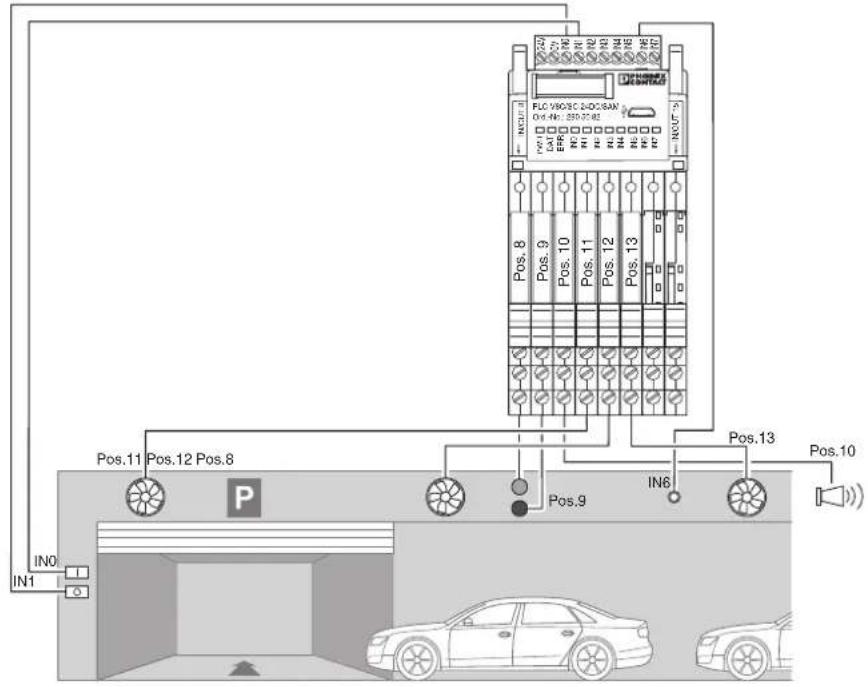
text_image
FLC V803C 2-DC/SAN V6.1.1: 339-70.82 V6.1.2: 339-70.82 V6.1.3: 339-70.82 V6.1.4: 339-70.82 V6.1.5: 339-70.82 V6.1.6: 339-70.82 V6.1.7: 339-70.82 V6.1.8: 339-70.82 V6.1.9: 339-70.82 V6.1.10: 339-70.82 V6.1.11: 339-70.82 V6.1.12: 339-70.82 V6.1.13: 339-70.82 V6.1.14: 339-70.82 V6.1.15: 339-70.82 V6.1.16: 339-70.82 V6.1.17: 339-70.82 V6.1.18: 339-70.82 V6.1.19: 339-70.82 V6.1.20: 339-70.82 V6.1.21: 339-70.82 V6.1.22: 339-70.82 V6.1.23: 339-70.82 V6.1.24: 339-70.82 V6.1.25: 339-70.82 V6.1.26: 339-70.82 V6.1.27: 339-70.82 V6.1.28: 339-70.82 V6.1.29: 339-70.82 V6.1.30: 339-70.82 V6.1.31: 339-70.82 V6.1.32: 339-70.82 V6.1.33: 339-70.82 V6.1.34: 339-70.82 V6.1.35: 339-70.82 V6.1.36: 339-70.82 V6.1.37: 339-70.82 V6.1.38: 339-70.82 V6.1.39: 339-70.82 V6.1.40: 339-70.82 Pos.8 Pos.9 Pos.10 Pos. Pos.11 Pos.12 Pos. Pos. Pos. IN6 Pos. IN1 INO P Car CarFigure 7-1 Structure for underground parking garage ventilation
| Quantity | Description | Order designation | Order number |
| 1 Stand-alone module PLC-V8C/SC-24DC/SAM 2905082 | |||
| 6 Relay module PLC-RSC-24DC/1/ACT 2966171 | |||
| 2 Empty socket PLC-BSC-24DC/21 2966016 | |||
7.1.2 LOGIC+ program
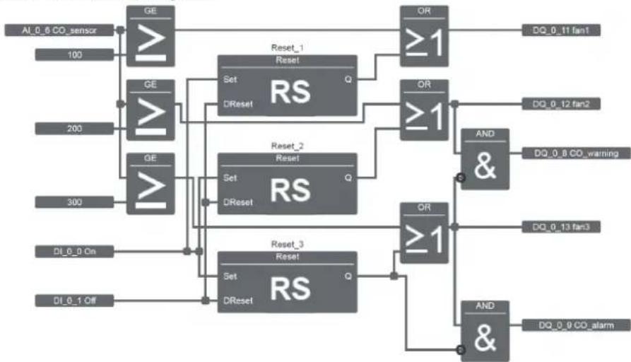
flowchart
graph TD
    A["AI_0_6 CO_sensor"] --> B["GE"]
    B --> C["Reset_1 Reset"]
    C --> D["OR ≥1"]
    D --> E["DQ_0_11 fan1"]
    F["100"] --> G["GE"]
    G --> H["Set DReset"]
    H --> I["RS"]
    J["200"] --> K["GE"]
    K --> L["Set DReset"]
    L --> M["RS"]
    N["300"] --> O["GE"]
    O --> P["Set DReset"]
    P --> Q["RS"]
    R["DI_0_0 On"] --> S["Reset_2 Reset"]
    T["DI_0_1 Off"] --> U["Reset_3 Reset"]
    V["OR ≥1"] --> W["DQ_0_8 CO_warning"]
    X["OR ≥1"] --> Y["DQ_0_12 fan2"]
    Z["OR ≥1"] --> AA["DQ_0_13 fan3"]
    AB["AND &"] --> AC["DQ_0_9 CO_alarm"]
    AD["AND &"] --> AE["DQ_0_9 CO_alarm"]
Figure 7-2 Underground parking garage ventilation code
7.1.3 Inputs and outputs used
Table 7-1 Inputs
| Item ID Label Description | ||
| IN0 DI_0_0 On Manual activation of all fans | ||
| IN1 DI_0_1 Off Switches manual activation off again | ||
| IN6 AI_0_6 CO_sensor CO sensor | ||
Table 7-2 Outputs
7.2 Sliding door system
A sliding door system is to be controlled with PLC logic.
In this application example, an electrically powered sliding door system is to be controlled with PLC logic. The door is to be actuated by two buttons in the building, button T1 (Open) and button T2 (Close), induction loops in the floor (loop) on exit or a key switch at the door.
The door system is to be opened and closed as per the functional sequence below.
Opening and closing the door via buttons T1 and T2 in the building
When button T1 is actuated, the door opens and moves to the end position which is sensed via a limit switch. If button T1 or T2 is actuated while the door is being opened, the operation is stopped. The door can now be opened by actuating button T1 or closed by actuating button T2 (limit switch).
Opening the door by means of the induction loop
When the induction loop gives a signal, the door opens to the end position, regardless of whether the door is completely closed or partially open. If button T1 or T2 is actuated while the door is being opened, the operation is stopped. The door can now be opened by actuating button T1 or closed by actuating button T2. The induction loop only responds again if the door has been completely closed or opened by actuating the button or the key switch. If the door opens or closes by actuating the button or the key switch, the function of the induction loop is blocked.
Opening and closing the door via the key switch at the door
The key switch has three positions: Open, Automatic, Close. If the key switch is set to the "Open" position, the door opens and moves to the end position which is sensed via a limit switch. If the key switch is set to the "Automatic" position while the door is being opened, the operation is stopped. The door can now be opened or closed by setting the key switch to the "Open" or "Close" position. The key switch only responds if it remains in the relevant position for at least two seconds. The key switch has priority over the induction loop and the buttons in the building. When the key switch is permanently set to the "Close" position, the door cannot be opened, likewise when the door is set to the "Open" position the door cannot be closed. The induction loop and the button only respond when the key switch is in the "Automatic" position.
Safety rail
The door is monitored by a safety rail when it is being closed. If the safety rail has detected a fault, the operation is stopped or cannot be started. The button in the building only responds if no fault is indicated by the safety rail. The key switch must first be returned to the "Automatic" position after a fault.
An optical signal light warns when the sliding door system is being opened and closed and makes people in the vicinity aware of the operation.
7.2.1 Hardware structure
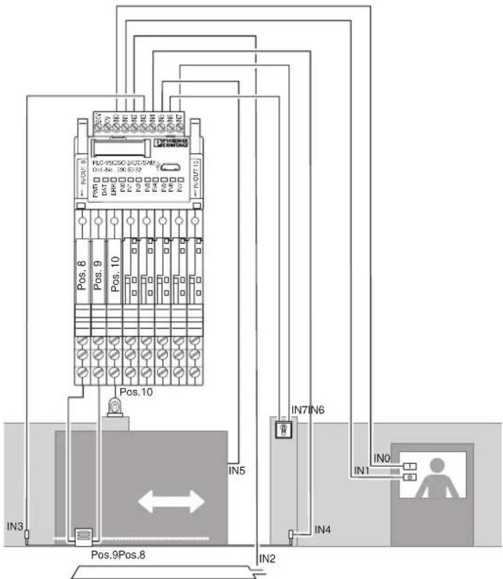
text_image
PLC-95CSCG-260CSW/ Out-No: 390.50.92 Pos. 8 Pos. 9 Pos. 10 Pos.10 IN3 IN5 IN7 IN6 IN1 IN4 IN2 Pos.9Pos.8Figure 7-3 Structure for sliding door system
| Quantity | Description | Order designation | Order number |
| 1 Stand-alone module PLC V8C/SC-24DC/SAM 2905082 | |||
| 3 Relay modules PLC-RSC-24DC/1/ACT 2966171 | |||
| 5 Empty socket PLC-BSC-24DC/21 2966016 | |||
7.2.2 LOGIC+ program
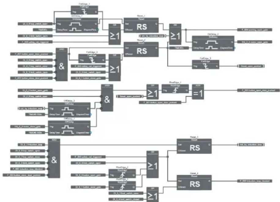
flowchart
graph TD
    subgraph Power_Signments
        direction TB
        A["AND &"] --> B["RS"]
        C["OR"] --> B
        D["Set Diffused"] --> B
        E["Reset_1"] --> B
        F["RS"] --> G["≥1"]
        H["RS"] --> I["≥1"]
        J["OnClose_2"] --> K["OnClose_1"]
        L["F-004 input, open, gate"] --> M["F-004 input, open, gate"]
        N["F-101 input, open, gate"] --> O["F-101 input, open, gate"]
        P["F-002 input, open, gate"] --> Q["F-002 input, open, gate"]
    end

    subgraph Power_Signments with Signals
        direction TB
        R["AND &"] --> S["RS"]
        T["OR"] --> S
        U["Set Diffused"] --> S
        V["Reset_1"] --> W["Reset_2"]
        X["RS"] --> Y["≥1"]
        Z["F-004 input, open, gate"] --> AA["F-004 input, open, gate"]
        AB["F-101 input, open, gate"] --> AC["F-101 input, open, gate"]
        AD["F-002 input, open, gate"] --> AE["F-002 input, open, gate"]
        AF["F-101 input, open, gate"] --> AG["F-101 input, open, gate"]
        AH["F-004 input, open, gate"] --> AI["F-004 input, open, gate"]
    end

    subgraph Power_Signments with Signals
        direction TB
        AJ["AND &"] --> AK["RS"]
        AL["F-004 input, open, gate"] --> AM["F-004 input, open, gate"]
        AN["F-101 input, open, gate"] --> AO["F-101 input, open, gate"]
        AP["F-002 input, open, gate"] --> AQ["F-002 input, open, gate"]
        AR["F-101 input, open, gate"] --> AS["F-101 input, open, gate"]
        AT["F-101 input, open, gate"] --> AU["F-101 input, open, gate"]
    end

    subgraph Power_Signments with Signals
        direction TB
        AV["F-004 input, open, gate"] --> AW["F-004 input, open, gate"]
        AX["F-101 input, open, gate"] --> AY["F-101 input, open, gate"]
        AZ["F-002 input, open, gate"] --> BA["F-002 input, open, gate"]
    end

    subgraph Power_Signments with Signals
        direction TB
        ARF["F-004 input, open, gate"] --> ASF["F-004 input, open, gate"]
        ATF["F-101 input, open, gate"] --> AUF["F-101 input, open, gate"]
        AVF["F-101 input, open, gate"] --> AWF["F-101 input, open, gate"]
        AXF["F-101 input, open, gate"] --> AYF["F-101 input, open, gate"]
        ATX["F-101 input, open, gate"] --> AUX["F-101 input, open, gate"]
    end
Figure 7-4 Sliding door system open_gate code
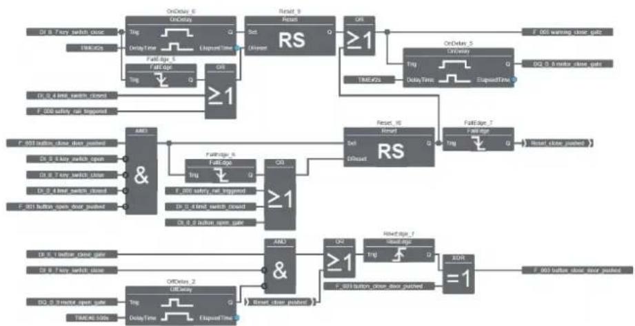
flowchart
graph TD
    A["OnDelay 6 OnDelay"] --> B["Reset 9"]
    B --> C["RS"]
    C --> D["OnDelay 5 Closed"]
    D --> E["Reset IR Reset"]
    E --> F["RS"]
    F --> G["Reset IR Reset"]
    G --> H["F-001 warning close gate"]
    A --> I["Ting Delay Time Elapsed Time"]
    I --> J["OnDelay 5 Closed"]
    J --> K["Reset IR Reset"]
    K --> L["F-001 warning close gate"]
    A --> M["Ting Delay Time Elapsed Time"]
    M --> N["OnDelay 5 Closed"]
    N --> O["Reset IR Reset"]
    O --> P["F-001 warning close gate"]
    A --> Q["Ting Delay Time Elapsed Time"]
    Q --> R["OnDelay 5 Closed"]
    R --> S["Reset IR Reset"]
    S --> T["F-001 warning close gate"]
    A --> U["Ting Delay Time Elapsed Time"]
    U --> V["OnDelay 5 Closed"]
    V --> W["Reset IR Reset"]
    W --> X["F-001 warning close gate"]
    A --> Y["Ting Delay Time Elapsed Time"]
    Y --> Z["OnDelay 5 Closed"]
    Z --> AA["Reset IR Reset"]
    AA --> AB["F-001 warning close gate"]
    A --> AC["Ting Delay Time Elapsed Time"]
    AC --> AD["OnDelay 5 Closed"]
    AD --> AE["Reset IR Reset"]
    AE --> AF["F-001 warning close gate"]
    A --> AG["Ting Delay Time Elapsed Time"]
    AG --> AH["OnDelay 5 Closed"]
    AH --> AI["Reset IR Reset"]
    AI --> AJ["F-001 warning close gate"]
    A --> AK["Ting Delay Time Elapsed Time"]
    AK --> AL["OnDelay 5 Closed"]
    AL --> AM["Reset IR Reset"]
    AM --> AN["F-001 warning close gate"]
    A --> AO["Ting Delay Time Elapsed Time"]
    AO --> AP["OnDelay 5 Closed"]
    AP --> AQ["Reset IR Reset"]
    AQ --> AR["F-001 warning close gate"]
    A --> AS["Ting Delay Time Elapsed Time"]
    AS --> AT["OnDelay 5 Closed"]
    AT --> AU["Reset IR Reset"]
    AU --> AV["F-001 warning close gate"]
    A --> AW["Ting Delay Time Elapsed Time"]
    AW --> AX["OnDelay 5 Closed"]
    AX --> AY["Reset IR Reset"]
    AY --> AZ["F-001 warning close gate"]
    A --> BA["Ting Delay Time Elapsed Time"]
    BA --> BB["OnDelay 5 Closed"]
    BB --> BC["Reset IR Reset"]
    BC --> BD["F-001 warning close gate"]
Figure 7-5 Sliding door system close_gate code
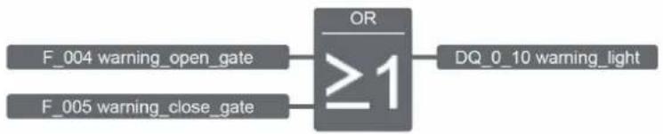
flowchart
graph LR
    A["F_004 warning_open_gate"] --> C["OR ≥1"]
    B["F_005 warning_close_gate"] --> C
    C --> D["DQ_0_10 warning_light"]
Figure 7-6 Sliding door system warning_light code
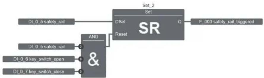
flowchart
graph LR
    A["DI_0_5 safety_rail"] --> B["AND &"]
    C["DI_0_5 safety_rail"] --> B
    D["DI_0_6 key_switch_open"] --> B
    E["DI_0_7 key_switch_close"] --> B
    B --> F["Set_2 Set"]
    F --> G["Q"]
    G --> H["F_000 safety_rail_triggered"]
    B --> I["Reset"]
    I --> J["SR"]
Figure 7-7 Sliding door system safety_rail code
7.2.3 Inputs and outputs used
Table 7-3 Inputs
| Item ID | Label Description | |
| IN0 DI_0_0 | button_open_gate Button T1 (open door) | |
| IN1 DI_0_1 | button_close_gate Button T2 (close door) | |
| IN2 DI_0_2 | induction_loop Induction loop | |
| IN3 DI_0_3 | limit_switch_open Limit switch: door closed | |
| IN4 DI_0_4 | limit_switch_closed Limit switch: door open | |
| IN5 DI_0_5 | safety_rail Safety rail | |
| IN6 DI_0_6 | key_switch_open Key switch in “Open” position | |
| IN7 DI_0_7 | key_switch_close Key switch in “Close” position |
Table 7-4 Outputs
| Item | ID | Label | Description |
| 8 | DQ_0_8 | motor_close_gate Motor control to open door | |
| 9 | DQ_0_9 | motor_open_gate | Motor control to close door |
| 10 | DQ_0_10 | warning_light | Orange warning light |
Table 7-5 Flags
| ID Label | Description | |
| F_000 | safety_rail_triggered The safety rail has been triggered | |
| F_001 | button_open_door_pushed | Button T1 “Open door” has been pushed |
| F_002 | induction_loop blocked Flag to block the induction loop | |
| F_003 | button_close_door_pushed Button T2 “Close door” has been pushed | |
| F_004 | warning_open_gate Warning flag for “Door opening” | |
| F_005 | warning_close_gate Warning flag for “Door closing” | |
7.3 Temperature monitoring with adjustable switching hysteresis
A medium is to be kept within a temperature range with PLC logic.
Switching hystereses are already used for temperature monitoring in many applications, e.g., on heating coils or when switching on fans. In this example, a heated medium is kept within a temperature range of 40^ C ... 80^ C. The current temperature is detected via a Pt 100 sensor and is converted to a 0 V ... 10 V standard signal via a temperature transducer. PLC logic reads this value at input Al_0_6. If the value is less than or equal to 40^ C, the heating coil is switched on via output DQ_0_8. As soon as a temperature of 80^ C is reached, the heating coil is switched off and is not switched on again until the temperature of the medium has dropped to 40^ C.
The temperature transducer is configured to a measuring range span of 0^ C ... 200^ C (corresponds to 0 V ... 10 V). LOGIC+ converts the standard voltage into values from 0 ... 1000. 40^ C therefore corresponds to a set point of 200 and 80^ C to a set point of 400. The specifications are selected in LOGIC+ accordingly.
In this example, PLC logic monitors two heating vessels. PLC logic reads the temperature of the second medium at input AI_0_7 and switches the heating coil via output DQ_0_9.
7.3.1 Hardware structure
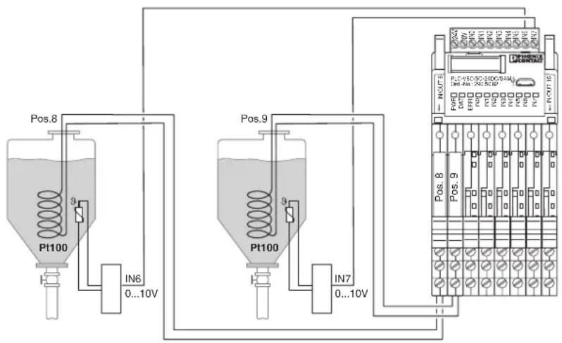
flowchart
graph TD
    A["Pt100"] -->|9| B["IN6 0...10V"]
    C["Pt100"] -->|9| D["IN7 0...10V"]
    E["AC 16"] --> F["PLC-NEO-CC-2HDC-54M 14H-4H+ PNC-57.0P"]
    G["AC 16"] --> H["PLC-NEO-CC-2HDC-54M 14H-4H+ PNC-57.0P"]
    I["AC 16"] --> J["PLC-NEO-CC-2HDC-54M 14H-4H+ PNC-57.0P"]
    K["AC 16"] --> L["PLC-NEO-CC-2HDC-54M 14H-4H+ PNC-57.0P"]
    M["AC 16"] --> N["PLC-NEO-CC-2HDC-54M 14H-4H+ PNC-57.0P"]
    O["AC 16"] --> P["PLC-NEO-CC-2HDC-54M 14H-4H+ PNC-57.0P"]
    Q["AC 16"] --> R["PLC-NEO-CC-2HDC-54M 14H-4H+ PNC-57.0P"]
    S["AC 16"] --> T["PLC-NEO-CC-2HDC-54M 14H-4H+ PNC-57.0P"]
    U["AC 16"] --> V["PLC-NEO-CC-2HDC-54M 14H-4H+ PNC-57.0P"]
    W["AC 16"] --> X["PLC-NEO-CC-2HDC-54M 14H-4H+ PNC-57.0P"]
    Y["AC 16"] --> Z["PLC-NEO-CC-2HDC-54M 14H-4H+ PNC-57.0P"]
    AA["AC 16"] --> AB["PLC-NEO-CC-2HDC-54M 14H-4H+ PNC-57.0P"]
    AC["AC 16"] --> AD["PLC-NEO-CC-2HDC-54M 14H-4H+ PNC-57.0P"]
    AE["AC 16"] --> AF["PLC-NEO-CC-2HDC-54M 14H-4H+ PNC-57.0P"]
    AG["AC 16"] --> AH["PLC-NEO-CC-2HDC-54M 14H-4H+ PNC-57.0P"]
    AI["AC 16"] --> AJ["PLC-NEO-CC-2HDC-54M 14H-4H+ PNC-57.0P"]
    AK["AC 16"] --> AL["PLC-NEO-CC-2HDC-54M 14H-4H+ PNC-57.0P"]
    AM["AC 16"] --> AN["PLC-NEO-CC-2HDC-54M 14H-4H+ PNC-57.0P"]
    AO["AC 16"] --> AP["PLC-NEO-CC-2HDC-54M 14H-4H+ PNC-57.0P"]
    AQ["AC 16"] --> AR["PLC-NEO-CC-2HDC-54M 14H-4H+ PNC-57.0P"]
    AS["AC 16"] --> AT["PLC-NEO-CC-2HDC-54M 14H-4H+ PNC-57.0P"]
    AU["AC 16"] --> AV["PLC-NEO-CC-2HDC-54M 14H-4H+ PNC-57.0P"]
    AW["AC 16"] --> AX["PLC-NEO-CC-2HDC-54M 14H-4H+ PNC-57.0P"]
    AX --> AXA["Pos.8"]
    AX --> AXB["Pos.9"]
Figure 7-8 Structure for temperature monitoring with adjustable switching hysteresis
| Quantity | Description | Order designation | Order number |
| 1 Stand-alone module PLC V8C/SC-24DC/SAM 2905082 | |||
| 2 Relay modules PLC-RSC-24DC/21 2966171 | |||
| 6 Empty socket | PLC-BSC-24DC/21 2966016 | ||
7.3.2 LOGIC+ program
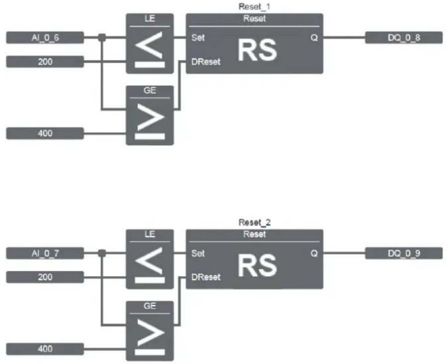
flowchart
graph TD
    A["AI_0_6"] --> B["LE"]
    C["200"] --> B
    D["400"] --> E["GE"]
    B --> F["Set"]
    B --> G["DReset"]
    H["Reset_1"] --> I["RS"]
    J["Reset"] --> K["Q"]
    L["DQ_0_8"] --> M["RS"]
    N["Reset_2"] --> O["RS"]
    P["Reset"] --> Q["Q"]
    R["AI_0_7"] --> S["LE"]
    T["200"] --> S
    U["400"] --> V["GE"]
    W["Reset"] --> X["DReset"]
    Y["DQ_0_9"] --> Z["RS"]
Figure 7-9 Temperature monitoring with adjustable switching hysteresis code
7.3.3 Inputs and outputs used
Table 7-6 Inputs
| Item ID Label Description | ||
| IN6 AI_0_6 | - Analog input for temperature measurement in medium 1 | |
| IN7 AI_0_7 | - Analog input for temperature measurement in medium 2 | |
Table 7-7 Outputs
| Item ID Label Description | ||
| 8 DQ_0_8 - | Output to switch on the heating coil in medium 1 | |
| 9 DQ_0_9 - | Output to switch on the heating coil in medium 2 | |
7.4 Conveyor belt system
A conveyor belt system with three belts is to be controlled with PLC logic. The conveyor belts should not be overloaded as a result of incorrect startup.
The system is switched on and off via two buttons (IN0, IN1). The conveyor belts only start up if a container is detected behind the last conveyor belt (limit switch at IN2).
The conveyor belts start up in the following order: first the last conveyor belt (Motor3, DQ_10), then in 5 s intervals the second conveyor belt (Motor2, DQ_09) and then the first conveyor belt (Motor1, DQ_08). This ensures that a conveyor belt is not overloaded. When the Off button is actuated, the same procedure is performed in reverse order. First conveyor belt 1 stops, followed by conveyor belt 2 and then conveyor belt 3.
7.4.1 Hardware structure
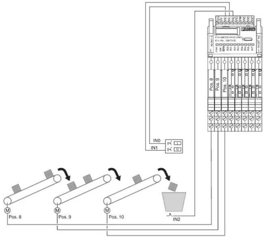
flowchart
graph TD
    A["Motor Position 8"] --> B["Motor Position 9"]
    B --> C["Motor Position 10"]
    C --> D["Output: IN2"]
    E["IN0"] --> F["Control Unit"]
    G["IN1"] --> F
    H["IN2"] --> F
    I["IC Control Panel"] --> J["Pin 8"]
    K["AC Control Panel"] --> L["Pin 9"]
    M["DC Control Panel"] --> N["Pin 10"]
    O["IG Control Panel"] --> P["Pin 11"]
    Q["IG Output Panel"] --> R["Pin 12"]
Figure 7-10 Structure for conveyor belt system
| Quantity | Description | Order designation | Order number |
| 1 Stand-alone module PLC V8C/SC-24DC/SAM 2905082 | |||
| 3 Relay modules PLC-RSC-24DC/1/ACT 2966171 | |||
| 5 Empty socket PLC-BSC-24DC/21 | 2966016 | ||
7.4.2 LOGIC+ program
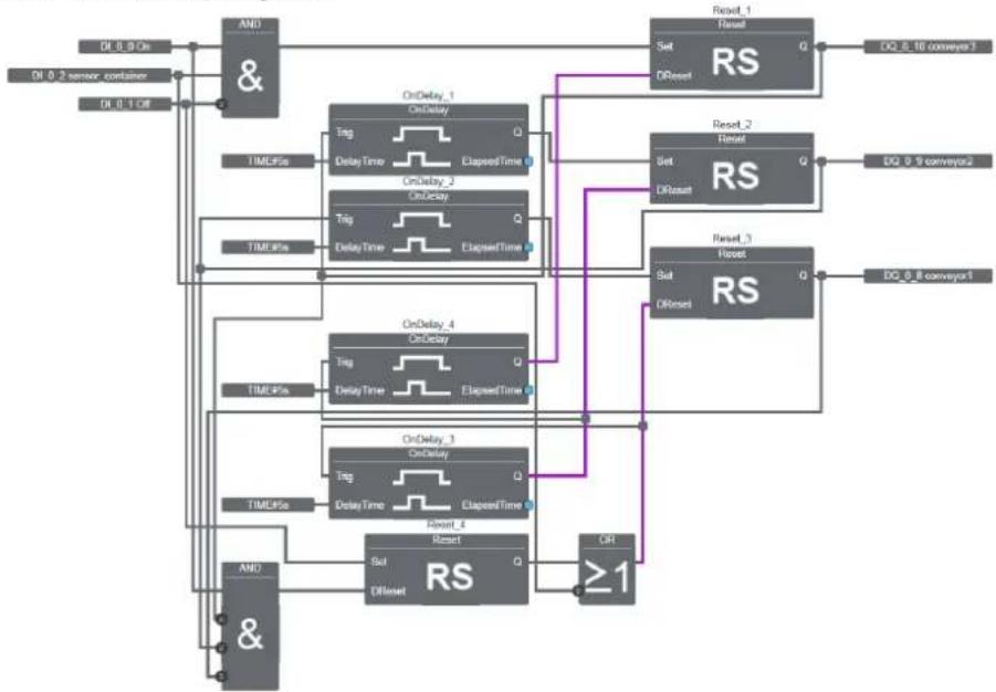
flowchart
graph TD
    A["OR 0.9 Pin"] --> B["&"]
    C["OR 0.2 sensor container"] --> B
    D["OR 0.1 Off"] --> B
    B --> E["OnDelay_1 OnDelay"]
    E --> F["Trg DelayTime ElapsedTime Q"]
    F --> G["OnDelay_2 OnDelay"]
    G --> H["Trg DelayTime ElapsedTime Q"]
    H --> I["RS Reset"]
    I --> J["Set ORReset"]
    J --> K["Reset_1 Reset"]
    K --> L["RS Reset"]
    L --> M["Set ORReset"]
    M --> N["Reset_2 Reset"]
    N --> O["RS Reset"]
    O --> P["Set ORReset"]
    P --> Q["Reset_3 Reset"]
    Q --> R["RS Reset"]
    R --> S["Set ORReset"]
    S --> T["Reset_4 Reset"]
    T --> U["RS Reset"]
    U --> V["Set ORReset"]
    V --> W["CR1 ≥1"]
    W --> X["AND &"]
    X --> Y["OnDelay_4 OnDelay"]
    Y --> Z["Trg DelayTime ElapsedTime Q"]
    Z --> AA["OnDelay_3 OnDelay"]
    AA --> AB["Trg DelayTime ElapsedTime Q"]
    AB --> AC["RS Reset"]
    AC --> AD["Set ORReset"]
    AD --> AE["Reset_1 Reset"]
    AE --> AF["RS Reset"]
    AF --> AG["Set ORReset"]
    AG --> AH["Reset_2 Reset"]
    AH --> AI["RS Reset"]
    AI --> AJ["Set ORReset"]
    AJ --> AK["Reset_3 Reset"]
    AK --> AL["RS Reset"]
    AL --> AM["Set ORReset"]
    AM --> AN["Reset_4 Reset"]
    AN --> AO["RS Reset"]
    AO --> AP["Set ORReset"]
    AP --> AQ["Reset_5 Reset"]
    AQ --> AR["RS Reset"]
    AR --> AS["Set ORReset"]
    AS --> AT["Reset_6 Reset"]
    AT --> AU["RS Reset"]
    AU --> AV["Set ORReset"]
    AV --> AW["Reset_7 Reset"]
    AW --> AX["RS Reset"]
    AX --> AY["Set ORReset"]
    AY --> AZ["Reset_8 Reset"]
    AZ --> BA["RS Reset"]
    BA --> BB["Set ORReset"]
    BB --> BC["Reset_9 Reset"]
    BC --> BD["RS Reset"]
    BD --> BE["Set ORReset"]
    BE --> BF["Reset_10 Reset"]
    BF --> BG["DQ 0.16 conveyor3"]
    BG --> BH["DQ 0.9 conveyor2"]
    BH --> BI["DQ 0.8 conveyor1"]
Figure 7-11 Conveyor belt system code
7.4.3 Inputs and outputs used
Table 7-8 Inputs
| Item ID Label Description | ||
| IN0 DI_0_0 On Switches the conveyor belt system on | ||
| IN1 DI_0_1 Off Switches the conveyor belt system off | ||
| IN2 DI_0_2 sensor_container Sensor for detecting the container | ||
Table 7-9 Outputs
| Item ID Label Description | |||
| 8 DQ_0_8 | conveyor1 | Motor control for conveyor belt 1 | |
| 9 DQ_0_9 | conveyor2 | Motor control for conveyor belt 2 | |
| 10 | DQ_0_10 | conveyor3 | Motor control for conveyor belt 3 |
A Technical data
| Criterion Value | |
| Supply | |
| Supply voltage 24 V DC | |
| Supply voltage range 19.2 V DC ... 26.4 V DC | |
| Maximum input current at UNPLC-V8C/...-24DC/SAMPLC-V8C/...-24DC/BMPLC-V8C/...-24DC/EM | 120 mA120 mA65 mA |
| Input data | Digital inputs |
| Number of inputs 8 (2 configurable as analog) | |
| Description of the input EN 61131-2 type 3 | |
| Input voltage 24 V DC | |
| Input current "0" signal < 1 mA | |
| Input current "1" signal 2.5 mA, typical | |
| Delay time 3 ms, maximum (basic module, stand-alone module)50 ms, maximum (extension module) | |
| Switching frequency 200 Hz, maximum (basic module, stand-alone module)20 Hz, maximum (extension module) | |
| Input data Analog inputs | |
| Number of inputs 2 (IN6 and IN7 are configurable as analog) | |
| Input voltage range | 0 V ... 10 V |
| Input resistance | >3.5 kΩ |
| Measured value deviation | ±3%, 0.15 V, minimum |
| Delay time 10 ms, maximum (basic module, stand-alone module)50 ms, maximum (extension module) | |
| Input data | Contacts for PLC-INTERFACE |
| Number of inputs | ≤8 |
| Description of the input | Technical data depends on the PLC used |
| Output data | |
| Number of outputs | ≤8 |
| Nominal output voltage 24 V DC | |
| Nominal current | 9 mA |
| Switching frequency 10 Hz, maximum (basic module, stand-alone module)10 Hz, maximum (extension module) | |
| Realtime clock | |
| Realtime clock accuracy | ±2 s/d |
| Buffer time | 24 h (capacitor) |
| General data | |
| Ambient temperature range Operation | -20°C ... 45°C |
| Ambient temperature range Storage/transport | -20°C ... 70°C |
| Humidity according to DIN EN 61131-2 | 10% ... 95% |
| Criterion | Value |
| Air pressure 86 kPa ... 106 kPa (2000 m, maximum) | |
| Sinusoidal vibrations according to IEC 60068-2-6 2g load, 2.5 hours in each space direction | |
| Shock according to IEC 60068-2-27 15g load for 1 ms, three shocks in each space direction | |
| Startup time when supply voltage on < 6 s | |
| Maximum supply voltage interruption < 4.5 ms | |
| Assembly instruction Can be plugged onto 8 x PLC-INTERFACE | |
| Degree of protection IP20 | |
| COMBICON connection Screw connectionSolid / stranded / AWG 0.14 ... 1.5 mm ^2 / 0.14 ... 1.5 mm ^2 / 28 - 16 | |
| COMBICON connection Push-in connectionSolid / stranded / AWG 0.14 ... 1.5 mm ^2 / 0.14 ... 1.5 mm ^2 / 26 - 16 | |
| Air clearances and creepage distances between the circuits | DIN EN 50178 |
| Rated insulation voltage 50 V | |
| Rated surge voltage 0.8 kV | |
| Insulation | Basic insulation |
| Conformance | CE-compliant |
Table A-1 Electromagnetic compatibility (EMC)
| Criterion | Test according to | Value |
| Noise emission | EN 55016-2-3 | - |
| Electrostatic discharge | EN 61000-4-2 | 6 kV contact discharge8 kV air discharge |
| Electromagnetic fields | EN 61000-4-3 | 10 V/m |
| Conducted high frequency | EN 61000-4-6 | 10 V |
| Burst EN 61000-4-4 | 2 kV supply and signal lines | |
| Surge | EN 61000-4-5 | 0.5 kV symmetrical to supply lines1 kV asymmetrical to supply lines1 kV asymmetrical to signal lines |
B Appendix for document lists
B 1 List of figures
Section 1
Figure 1-1: Entire system ....10
Section 2
Figure 2-1: Configuration with 10 inputs, 6 outputs .... 16
Figure 2-2: Configuration with 8 inputs, 8 outputs ....17
Figure 2-3: Configuration with 20 inputs, 12 outputs .... 18
Section 3
Figure 3-1: Connection and operating elements of stand-alone logic modules .....20
Figure 3-2: Connection and operating elements of basic logic modules ..... 21
Figure 3-3: Connection and operating elements of extension logic modules .....22
Figure 3-4: Connection and operating elements of PLC-INTERFACE terminal blocks 23
Figure 3-5: Basic circuit diagram for PLC-V8C/.../SAM 26
Figure 3-6: Basic circuit diagram for PLC-V8C/.../BM 26
Figure 3-7: Basic circuit diagram for PLC-V8C/.../EM .....27
Figure 3-8: Snapping the PLC-INTERFACE terminal blocks onto the DIN rail ..... 28
Figure 3-9: Logic module is fixed in place .....29
Figure 3-10: Actuating the eject levers to remove the logic modules ....31
Section 4
Figure 4-1: Power supply ....33
Figure 4-2: Integrated inputs ....34
Figure 4-3: Connecting integrated inputs ....34
Figure 4-4: PLC modules with screw connection ....37
Figure 4-5: PLC modules with Push-in connection .... 38
Figure 4-6: Wiring of digital inputs via PLC-INTERFACE terminal blocks ..... 39
Figure 4-7: Pin assignment of digital inputs via PLC-INTERFACE terminal blocks 40
Figure 4-8: Convenient connection of the sensor series ....41
Figure 4-9: Wiring of analog input modules ....42
Figure 4-10: Wiring of Pt 100/Pt 1000 temperature transducers .....42
Figure 4-11: Wiring of digital outputs via PLC-INTERFACE terminal blocks ..... 43
Figure 4-12: Pin assignment of digital outputs via PLC-INTERFACE terminal blocks 44
Figure 4-13: Convenient connection of the actuator series ....45
Figure 4-14: Wiring of analog outputs via PLC-INTERFACE terminal blocks ..... 46
Figure 4-15: PLC logic and PC connection .... 47
Section 5
Figure 5-3: Visualization ....52
Figure 5-4: Login 53
Figure 5-5: General configuration settings ....54
Figure 5-6: Configuring the realtime clock ....55
Figure 5-7: Setting the IP address ....56
Figure 5-8: Visualization configuration ....57
Figure 5-9: Editor - page overview ....58
Figure 5-10: Editor - page configuration ....59
Figure 5-11: Editor - variables ...... 60
Figure 5-12: Setting the password ....61
Figure 5-13: Starting the firmware update 62
Figure 5-14: Firmware update - selecting the file 63
Figure 5-15: Firmware update - progress indicator 64
Figure 5-16: Firmware update - emptying the cache 65
Figure 5-17: Overview of device information 66
Figure 5-18: LOGIC+ start page 68
Figure 5-19: LOGIC+ interface 69
Figure 5-20: Hardware configuration 72
Figure 5-21: Communication settings ....79
Figure 5-22: Determining the cycle time 82
Figure 5-23: Inserting the IFS-CONFSTICK 83
Figure 5-24: Bluetooth adapter 85
Figure 5-25: Mounting the PROFIBUS gateway and PLC logic 87
Figure 5-26: EM-PB-GATEWAY-IFS 88
Figure 5-27: Block diagram 89
Figure 5-28: Status LEDs 89
Figure 5-29: Interface system IOs 91
Figure 5-30: Function blocks .....91
Figure 5-31: Example program 92
Figure 5-32: Installing components ......93
Figure 5-33: User Properties > creating a user ....94
Figure 5-34: Loading device drivers ..... 94
Figure 5-35: Display of installed DTMs 95
Figure 5-36: Topology scan 96
Figure 5-37: Hardware structure 96
Figure 5-38: Opening the process data configuration .....97
Figure 5-39: Process data configuration: inputs - outputs ...... 98
Figure 5-40: Process data configuration: example 99
Figure 5-41: Inserting the gateway in the bus configuration .... 100
Figure 5-42: Setting the "Configuration via DTM" and "Byte order" entries ..... 101
Figure 5-43: Listing process words ...... 102
Figure 5-44: "PDC_IN" (input from DTM) and "PDC_OUT" (output from DTM) ..... 102
Section 6
Figure 6-1: Analog differential threshold value switch code ....121
Figure 6-2: Analog threshold value switch code 122
Figure 6-3: Analog comparator code 122
Figure 6-4: Pulse relay code 123
Figure 6-5: Interval time-delay relay with pulse output code 123
Figure 6-6: Edge-triggered interval time-delay relay 124
Section 7
Figure 7-1: Structure for underground parking garage ventilation .... 126
Figure 7-2: Underground parking garage ventilation code 127
Figure 7-3: Structure for sliding door system 129
Figure 7-4: Sliding door system open_gate code 130
Figure 7-5: Sliding door system close_gate code 130
Figure 7-6: Sliding door system warning_light code 131
Figure 7-7: Sliding door system safety_rail code 131
Figure 7-8: Structure for temperature monitoring with adjustable switching hysteresis 133
Figure 7-9: Temperature monitoring with adjustable switching hysteresis code .134
Figure 7-10: Structure for conveyor belt system 135
Figure 7-11: Conveyor belt system code ...... 136
B 2 List of tables
Section 1
Table 1-1: Frequently used information....9
Table 1-2: Possible applications....11
Section 2
Table 2-1: Corresponding PLC-INTERFACE terminal blocks.... 15
Section 3
Table 3-1: Diagnostic and status indicators....24
Table 3-2: Explanation of the symbols....25
Section 4
Table 4-1: Connection data for the 10-pos. COMBICON connector .... 33
Table 4-2: Properties of the integrated inputs ...... 34
Table 4-3: Stand-alone logic module and basic logic module (station 0)....35
Table 4-4: First extension logic module (station 1)....35
Table 4-5: Second extension logic module (station 2)....35
Table 4-6: Recommended plug-in bridges....36
Table 4-7: Stand-alone logic module and basic logic module (station 0)....36
Table 4-8: First extension logic module (station 1)....37
Table 4-9: Second extension logic module (station 2)....37
Section 5
Table 5-1: Windows 7 Service Pack 1 ....67
Table 5-2: Windows 8.1....67
Table 5-3: Windows 10....67
Table 5-4: Areas of the LOGIC+ interface....69
Table 5-5: Buttons in the tool bar....70
Table 5-6: Available functions/function blocks....73
Table 5-7: Memory required for standard functions/function blocks ..... 74
Table 5-8: Memory required for Interface System V1.1 ....75
Table 5-9: Memory required for Analog V1.1....76
Table 5-10: Memory required for Special V1.2 77
PLC logic
Table 5-11: Data item types....78
Table 5-12: Components for integration in PROFIBUS DP....86
Table 5-13: Status of the basic module....103
Table 5-14: Digital inputs/outputs of the basic module .... 104
Table 5-15: Analog inputs/outputs of the basic module ..... 105
Table 5-16: Status of extension module 1....105
Table 5-17: Inputs/outputs of extension module 1 .... 106
Table 5-18: Analog inputs of extension module 1....106
Table 5-19: Status of extension module 2....107
Table 5-20: Digital inputs/outputs of extension module 2....108
Table 5-21: Analog inputs of extension module 2....108
Table 5-22: Realtime clock....109
Table 5-23: Flags 000 ... 015....109
Table 5-24: Flags 016 ... 031 .... 110
Table 5-25: Flags 032 ... 047 .... 111
Table 5-26: Flags 048 ... 063....112
Table 5-27: Flags 064 ... 079 .... 113
Table 5-28: Flags 080 ... 095....114
Table 5-29: Flags 096 ... 111 .... 115
Table 5-30: Flags 112 ... 127 .... 116
Table 5-31: Time registers 000 ... 015....117
Table 5-32: Registers 000 ... 023....118
Table 5-33: INTERFACE system input 0 ... 15.... 119
Table 5-34: INTERFACE system output 0 ... 15.... 120
Section 7
Table 7-1: Inputs....127
Table 7-2: Outputs....127
Table 7-3: Inputs....131
Table 7-4: Outputs....131
Table 7-5: Flags....132
Table 7-6: Inputs....134
Table 7-7: Outputs....134
Table 7-8: Inputs....136
Table 7-9: Outputs....136
Appendix A
Table A-1: Electromagnetic compatibility (EMC).... 138