IBS RL 24 DIO 8/8/8-T - Uncategorized Phoenix - Free user manual and instructions
Find the device manual for free IBS RL 24 DIO 8/8/8-T Phoenix in PDF.


User questions about IBS RL 24 DIO 8/8/8-T Phoenix
0 question about this device. Answer the ones you know or ask your own.
Ask a new question about this device
Download the instructions for your Uncategorized in PDF format for free! Find your manual IBS RL 24 DIO 8/8/8-T - Phoenix and take your electronic device back in hand. On this page are published all the documents necessary for the use of your device. IBS RL 24 DIO 8/8/8-T by Phoenix.
USER MANUAL IBS RL 24 DIO 8/8/8-T Phoenix
Configuring and Installing the Rugged Line Product Range
Designation: IBS RL SYS PRO UM E
Revision: BC01
Order No.: 27 43 78 9
This update is valid for:
All modules of the Rugged Line product range
© Phoenix Contact 06/2000
Please Observe The Following Notes:
In order to guarantee the safe use of your device, we recommend that you read this manual carefully. The following notes give you information on how to use this manual.
Requirements on the User Group
The use of products described in this manual is oriented exclusively to qualified electricians or persons instructed by them who are familiar with applicable national standards. Phoenix Contact assumes no liability for erroneous handling or damage to products from Phoenix Contact or external products resulting from disregard of information contained in this manual.
Explanation of Symbols Used
The attention symbol refers to an operating procedure which, if not carefully followed, could result in damage to equipment or personal injury.
The note symbol informs you of conditions that must strictly be observed to achieve error-free operation. It also gives you tips and advice on hardware and software optimization to save you extra work.
The text symbol refers to detailed sources of information (manuals, data sheets, literature, etc.) on the subject matter, product, etc. This text also provides helpful information for the orientation in the manual.
We are Interested in Your Opinion
We are constantly attempting to improve the quality of our manuals.
Should you have any suggestions or recommendations for improvement of the contents and layout of our manuals, we would appreciate it if you would send us your comments. Please use the universal fax form at the back of the manual for this.

text_image
Warning symbol, hand gesture pointing to document, and warning triangle with exclamation markStatement of Legal Authority
This manual, including all illustrations contained herein, is copyright protected. Use of this manual by any third party in departure from the copyright provision is forbidden. Reproduction, translation, or electronic or photographic archiving or alteration requires the express written consent of Phoenix Contact. Violators are liable for damages.
Phoenix Contact reserves the right to make any technical changes that serve the purpose of technical progress.
Phoenix Contact reserves all rights in the case of patent award or listing of a registered design. External products are always named without reference to patent rights. The existence of such rights shall not be excluded.
Internet
Current product information is also available on the Internet at www.phoenixcontact.com.
Table of Contents
1 Integrating Rugged Line into the INTERBUS System....1-3
1.1 The INTERBUS System.... 1-3
1.2 Example Topology of an INTERBUS Structure
With Rugged Line.... 1-4
1.3 Rugged Line Product Description 1-7
1.4 Structure of a Rugged Line Station.... 1-10
1.5 Diagnostic and Status Indicators.... 1-14
1.6 Conversion from Copper to Optical Fiber.... 1-20
2 Mounting and Installation 2-3
2.1 Mounting Distances.... 2-3
2.2 Housing Dimensions 2-4
2.3 Attaching the Mounting Plate 2-7
2.4 Mounting the Electronics Module.... 2-8
2.5 Connecting the Supply Voltage.... 2-10
2.6 Connecting the Bus (Copper).... 2-15
2.7 Connecting the Bus (Optical Fiber).... 2-19
2.8 Mounting Bus Connectors.... 2-23
2.9 Connecting Sensors/Actuators.... 2-25
3 Bus Operation Using Optical Fibers....3-3
3.1 Connecting Optical Fibers.... 3-3
3.2 Optical Diagnostics 3-3
3.3 Startup.... 3-5
3.4 Checking the Optical Fiber Connection.... 3-14
4 Single Channel Diagnostics 4-3
4.1 Enabling Single Channel Diagnostics 4-3
4.2 Setting the Address for Diagnostic Parameter Register 2...... 4-5
4.3 Reporting Diagnostic Information.... 4-7
4.4 Reading Diagnostic Information.... 4-8
4.5 Assignment of Diagnostic Parameter Register 2 4-11
4.6 Acknowledging Error Messages on the Modules...... 4-12
4.7 Deterioration of Optical Transmission.... 4-13
5 INTERBUS Software Configuration 5-3
5.1 INTERBUS Software.... 5-3
5.2 Addressing 5-6
6 Technical Data....6-3
6.1 INTERBUS System Data 6-3
6.2 Cable Lengths (INTERBUS System) 6-4
6.3 Rugged Line Technical Data.... 6-5
6.4 Conformance With EMC Directive 6-6
6.5 Cable Specifications.... 6-7
6.6 Technical Data for the Optical Fiber Interface.... 6-14
6.7 Ordering Data.... 6-15
A List of Devices for a Rugged Line System...... A-1
B Appendix.... B-1
Section 1
This section informs you about
– the Rugged Line product range as a component of the INTERBUS system.
Integrating Rugged Line into the INTERBUS System 1-3
1.1 The INTERBUS System....1-3
1.2 Example Topology of an INTERBUS Structure
With Rugged Line....1-4
1.3 Rugged Line Product Description 1-7
1.4 Structure of a Rugged Line Station....1-10
1.4.1 Structure of a Bus Terminal Module 1-12
1.4.2 Structure of an I/O Module 1-13
1.5 Diagnostic and Status Indicators....1-14
1.5.1 Bus Terminal Module Indicators 1-15
1.5.2 I/O Module Indicators....1-17
1.6 Conversion from Copper to Optical Fiber....1-20
1.6.1 Converter for Controller Boards....1-20
1.6.2 Converter for Rugged Line Modules....1-21
1 Integrating Rugged Line into the INTERBUS System
1.1 The INTERBUS System
INTERBUS is a serial bus system, which transmits data between control systems (e.g., PLCs, PCs, VMEbus computers, robot controllers etc.) and spatially distributed I/O modules that are connected to sensors and actuators (operating and display units, indicators, drives etc.).
INTERBUS has a ring structure. The ring structure allows INTERBUS to send and receive data simultaneously.
INTERBUS is a single master system, i.e., a master (e.g., controller board, control terminal) controls all devices of an INTERBUS ring.
From the master, all devices are connected to the bus system. Each device has separate lines for data transmission: one for forward data transfer and one for return data transfer. This eliminates the need for a return line from the last device to the first device that is necessary in a simple ring system. The forward and return lines run in one bus cable. From the installation point of view, INTERBUS has a tree structure as only one cable leads from one device to the next.
In the INTERBUS topology the single bus devices can be differentiated by means of their position in the system. For example, there are controller boards, bus terminal modules (BK modules) and remote bus devices.
Rugged Line is an INTERBUS system product family. Rugged Line modules are connected to an INTERBUS system using a bus terminal module. All modules of the product family are remote bus devices.
1.2 Example Topology of an INTERBUS Structure With Rugged Line
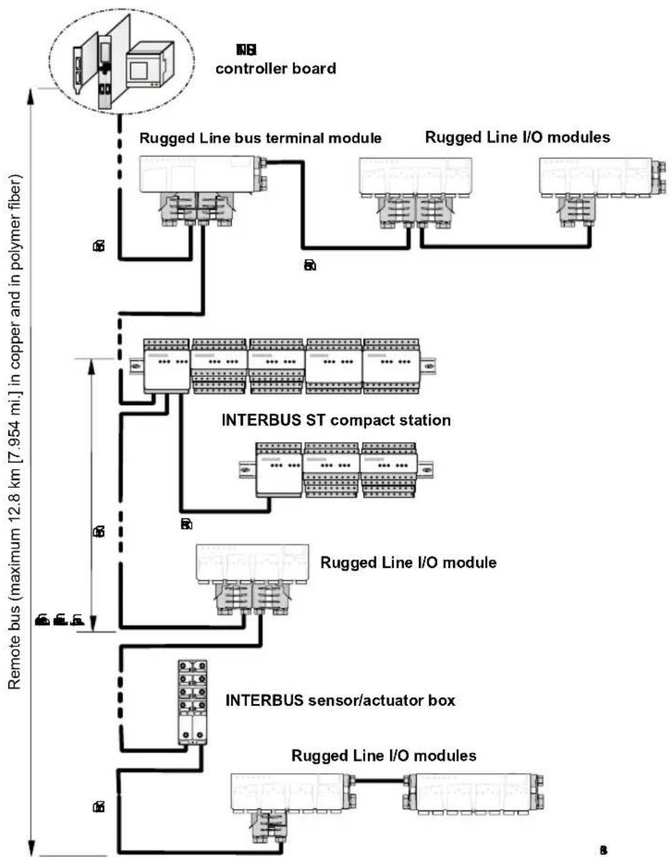
flowchart
graph TD
    A["controller board"] --> B["Rugged Line bus terminal module"]
    A --> C["Rugged Line I/O modules"]
    B --> D["INTERBUS ST compact station"]
    C --> D
    D --> E["Rugged Line I/O module"]
    E --> F["INTERBUS sensor/actuator box"]
    F --> G["Rugged Line I/O modules"]
    style A fill:#f9f,stroke:#333
    style B fill:#ccf,stroke:#333
    style C fill:#ccf,stroke:#333
    style D fill:#cfc,stroke:#333
    style E fill:#cfc,stroke:#333
    style F fill:#fcc,stroke:#333
    style G fill:#fcc,stroke:#333
Figure 1-1 Example of an INTERBUS system
Controller board The controller board takes over the master function in the INTERBUS system. It organizes the data traffic in the INTERBUS system, independent of the control or computer system in which it is installed.
Controller boards are available for a wide range of control and computer systems.
Tasks of the controller boards:
- Transmitting output data to the output modules
- Reading the input data from the input modules
- Monitoring INTERBUS
- Sending error messages to the host system
– Indicating diagnostic messages - Controlling the cyclic I/O protocol
Remote bus The remote bus connects a controller board with remote bus devices and interconnects remote bus devices.
Remote bus devices Remote bus devices are bus terminal modules, certain I/O modules, or a mixture of both. Each has a local supply voltage and an electrically isolated outgoing INTERBUS segment.
The maximum number of remote bus devices on INTERBUS is limited to 254.
Remote bus branch A remote bus branch is a branch off the remote bus. A branch is connected to the main line of the remote bus via a special bus terminal module. This bus terminal module allows for the connection and disconnection of the branching bus segment.
Bus terminal module (BK module) The first step in setting up a modular I/O station is to connect the bus terminal module to the INTERBUS remote bus cable. A bus terminal module divides the system into segments, thus allowing you to switch off single branches during operation.
A bus terminal module must be supplied with non-interruptible voltage. This means that the voltage may not be off at the same time as the subsystem if the whole bus system is to continue operation. If the supply voltage at a bus terminal module fails, the system stops and generates an error message for the bus segment.
Tasks of the bus terminal module:
- Updating the data signal (repeater function)
– Electrical isolation of the bus segments
Bus segment A bus segment consists of a bus terminal module and the I/O modules connected to it. The preceding cable is also part of the segment.
I/O modules Input/output modules connect INTERBUS to the sensors and actuators.
1.3 Rugged Line Product Description
Rugged Line modules are designed for use in systems engineering. With IP 67 protection, they are suitable for use without a control cabinet in harsh industrial conditions. They can, for example, be used on the tool platform, directly on welding robots, or in conveying systems.
Depending on the application area, these modules allow you to connect the bus and the supply voltage to the module from two sides.
QUICKON bus connectors are used to provide the module voltage supply for the bus logic/sensors (24 V DC) and actuators (24 V DC).
Versions The Rugged Line product family includes bus terminal modules for connecting a Rugged Line system to the INTERBUS remote bus:
- Bus terminal modules with remote bus branch (connections using copper cables)
- Bus terminal modules with remote bus branch (connections using fiber optics)
Modules are also available with digital input/output functions:
- Digital input/output module with eight inputs and eight outputs per four M12 sockets (load capacity of the outputs: maximum 500 mA per channel, concurrent channel derating of 50% )
– Digital input module with 16 digital inputs on eight M12 sockets - Digital output module with eight outputs on eight M12 sockets (load capacity: maximum 2 A per channel, concurrent channel derating of 50% )
All modules have either a copper or optical fiber connection. Modules with an optical fiber connection are available in two transmission rates (500 kbaud or 2 Mbaud).

Only use devices with a uniform transmission rate in a Rugged Line system. A mixture of devices with different transmission rates cannot be operated.
The following versions are available for the modules with an optical fiber connection and 2 Mbaud transmission rate:
– Reversing-load motor starter
- Digital input/output module with four inputs and two outputs on every two M12 sockets (in 4-slot housing)
- Module for segmenting the bus (bus terminal module without remote bus branch in 4-slot housing)
– Relay module for switching voltages up to 230 V

The reversing-load motor starter (IBS RL 400 MLR R DIO6/1-LK2MBD) and the relay module (IBS RL 24 DIO 8/8/8 RS-LK-2MBD) will not be considered in this user manual. Information on these modules can be found in the module-specific data sheets (see also "Ordering Data for Documentation" on page 6-19).
Diagnostics For modules with an optical fiber connection, the optical transmission power is monitored during operation and if necessary compensated for in limits (optical diagnostics).
The outputs are monitored individually for errors (single channel diagnostics), while the inputs are monitored in groups of four (group diagnostics).
System requirements To take full advantage of all the functions, the INTERBUS system must be operated with a Generation 4 (G4) controller board with firmware version 4.40 or later. This means that you have a Generation 4 controller board that can be operated with this firmware version.
For configuration operation, parameterization, and visualization of the system, IBS CMD SWT G4 software version 4.50 or later is available for standard controller boards.
When using a Field Controller or Remote Field Controller, PC WORX software is available, however the optical diagnostics are not shown in the current version (version 1.30).
Positioning Rugged Line modules can be mounted directly in systems or machines without additional protection measures (IP 67).
Mounting The module electronics is snapped onto a mounting plate for the Rugged Line product family. The mounting plate is first screwed onto a flat mounting surface. It is suitable for commonly used fixing systems, e.g., aluminum profiles, two-position attachment or Kempf terminal boxes.
Bus connection The bus can be connected to the modules from different sides. It is connected together with the supply voltage using QUICKON bus connectors.
I/O connection The sensors and actuators are connected to the I/O modules using 5-pos. M12 connectors.
1.4 Structure of a Rugged Line Station
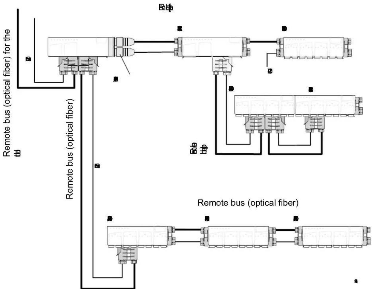
flowchart
graph TD
    A["Remote bus (optical fiber)"] --> B["Node 1"]
    A --> C["Node 2"]
    A --> D["Node 3"]
    A --> E["Node 4"]
    A --> F["Node 5"]
    G["Remote bus (optical fiber)"] --> H["Node 6"]
    G --> I["Node 7"]
    G --> J["Node 8"]
    G --> K["Node 9"]
    L["BIP"] --> M["Node 10"]
    N["BIP"] --> O["Node 11"]
    P["BIP"] --> Q["Node 12"]
    R["BIP"] --> S["Node 13"]
Figure 1-2 Rugged Line installation example (data transmission rate of 500 kbaud)

At maximum load the supply voltage of the last module must not fall below the required values (see "Measuring the Supply Voltage" on page 2-13).
Rugged Line modules are remote bus devices, i.e., they can be integrated directly into the remote bus. However, in some cases it can be useful to place a bus terminal module before the I/O modules, to segment the bus and to enable individual branches to be connected or disconnected during operation.
The system limits of the INTERBUS system apply between the remote bus devices (see "INTERBUS System Data" on page 6-3).
- When using copper cables, the entire remote bus from the controller board to the last connected remote bus module can have a length of up to 12.8km (7.954 mi.). A maximum of 254 remote bus devices can be connected. A maximum distance of 400m (1312.336 ft.) can be covered between two remote bus devices using copper cables.
- When using optical fibers, a maximum of 50 m (164.042 ft.) can be jumpered between two remote bus devices using fixed polymer fiber. When using flexible polymer fiber, 35 m (114.829 ft.) is possible.

The bus cable, that is pre-assembled by the user, must be at least 1 meter (3.281 ft.). For shorter paths only use cable jumpers from Phoenix Contact (IBS RL CONNECTION..., see "Ordering Data for Accessories" on page 6-15).
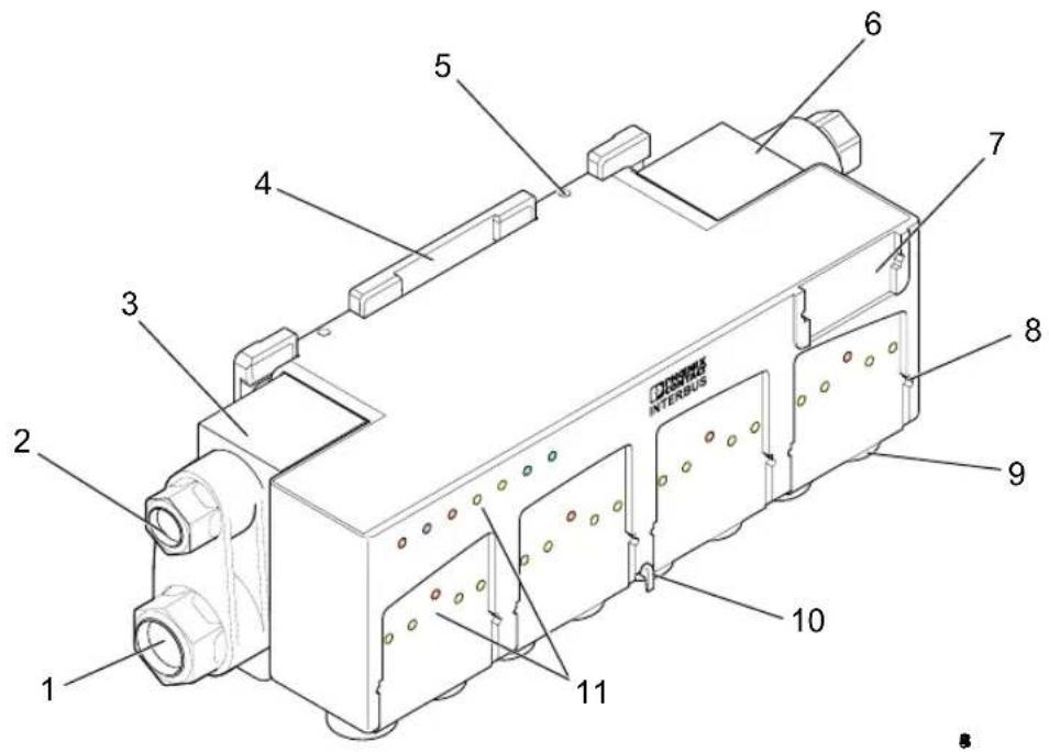
1.4.1 Structure of a Bus Terminal Module

text_image
DICCIESS INTERBUS 1 2 3 4 5 6 7 8 9 10Figure 1-3 Structure of an RL bus terminal module
1 Connection of the supply voltage (U S1 and U S2 )
2 INTERBUS remote bus connection
3 Bus connector (incoming remote bus)
4 Mounting plate
5 Hole for mounting screw (only for high degree of vibration)
6 Bus connector (outgoing remote bus)
7 Slot for labeling field for the module description
8 Bus connector (remote bus branch)
9 Button to release the module from the mounting plate
10 Diagnostic and status indicators
$$ U _ {S 1} = \text { supply of bus logic and sensors } + \text { voltage routing } $$
$$ U _ {S 2} = \text { supply of actuators } + \text { voltage routing } $$
1.4.2 Structure of an I/O Module
text_image
1 2 3 4 5 6 7 8 9 10 11 INTEGUSFigure 1-4 Structure of an I/O module
1 Connection of the supply voltage ( U_S1 and U_S2 ) U_S1= supply of bus logic and sensors + voltage routing U_S2= supply of actuators + voltage routing
2 INTERBUS remote bus connection
3 Bus connector (incoming remote bus)
4 Mounting plate
5 Hole for mounting screw (only for high degree of vibration)
6 Bus connector (outgoing remote bus)
7 Slot for labeling field for the module description
8 Slot for labeling field for user-specific I/O description
9 Connections for sensors and actuators
10 Button to release the module from the mounting plate
11 Diagnostic and status indicators
1.5 Diagnostic and Status Indicators
| For quick local error diagnostics, the modules have diagnostic and status indicators. | |
| Diagnostic indicators | The diagnostic indicators (red or green) indicate the type and location of the error. The module is functioning correctly if all of the green LEDs are on. |
| Status indicators | The status indicators (yellow) display the status of the relevant inputs/ outputs or the connected sensor or actuator. |
| Extended diagnostics | Rugged Line modules have extended diagnostics. A short circuit in the sensor supply is reported in groups each consisting of 4 inputs. If a short circuit occurs at an output, each channel is diagnosed individually. Information on the supply voltage is also reported. Information on I/O errors is sent to the control system with the precise specification of the error type and displayed using status indicators. |
| Optical diagnostics | For modules with an optical fiber connection, the quality of the transmission path is determined and compensated for in limits (optical diagnostics). With this diagnostic function it is possible to detect a gradual deterioration of the transmission path before transmission errors occur or transmission is interrupted.This transmission quality is available as information at the control system. If the system reserve of -3 dB is reached or exceeded during optical transmission, a warning for the appropriate interface is sent to the control system (MAU warning). In addition, information on the transmission quality is displayed on the module at which the transmission path starts (see "Diagnostic Indicators FO1 to FO3" on page 1-19). |
 | Refer to the module-specific data sheet for information about the diagnostic and status indicators on each module. |
1.5.1 Bus Terminal Module Indicators
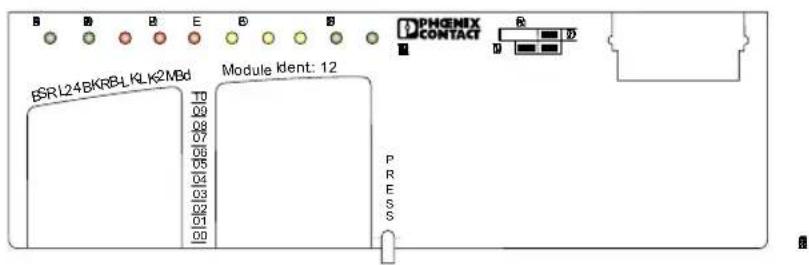
text_image
B B B E B B B BSRL24BKRB-LKLK2MBd Module Ident: 12 T0 T0 T0 T0 T0 T0 T0 T0 P R E SFigure 1-5 Fiber-optic bus terminal module indicators (example)
| IB DIAG | Green LED | INTERBUS diagnostics |
| OFF: | Supply voltage not present | |
| Flashing at 0.5 Hz: | Supply voltage present, bus not active | |
| Flashing at 2 Hz: | Supply voltage present, I/O error | |
| ON: | Supply voltage present, bus active, no I/O error | |
| RC | Green LED | Remote bus cable check |
| ON: | Data is sent to the incoming remote bus connection | |
| OFF: | Incoming remote bus connection defective or not active | |
| RD1 | Red LED | Remote bus status (remote bus disabled) |
| ON: | Outgoing remote bus switched off | |
| RD2 | Red LED | Status of the remote bus branch (remote bus disabled) |
| ON: | Remote bus branch switched off | |
| E | Red LED | Error message |
| ON: | Error in the remote bus branch | |
| FO1* | Yellow LED | Monitoring the incoming optical fiber path |
| ON: | Incoming optical fiber path not OK | |
| or system reserve reached during controlled operation ^ | ||
| OFF: | Incoming optical fiber path OK or not used | |
| FO2* | Yellow LED | Monitoring the outgoing optical fiber path |
| ON: | Outgoing optical fiber path not OK. | |
| or system reserve reached during controlled operation ^ | ||
| OFF: | Outgoing optical fiber path OK or not used | |
| FO3* Yellow LEDON:OFF: | Monitoring the optical fiber path of the remote bus branchOutgoing optical fiber path of the remote bus branch not OK or system reserve reached during controlled operation†Outgoing optical fiber path of the remote bus branch OK or not used |
| US1 Green LED | Monitoring the supply voltage US1 |
| OFF: | US1 not present |
| Flashing: | US1 below the permissible voltage range |
| ON: | US1 present |
| US2 Green LED | Monitoring the supply voltage US2 |
| Flashing: | US2 below the permissible voltage range / not present |
| ON: | US2 present |
* Only available for bus terminal modules with optical fiber connection. For additional explanation see page 1-19.
^ Controlled operation of optical fiber interfaces is only possible between two optical fiber devices, which are equipped with the INTERBUS protocol chip IBS SUPI 3 OPC (see Table 3-1 "INTERBUS devices with SUPI 3 OPC").
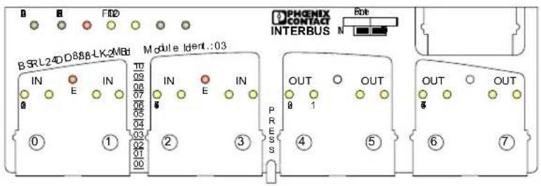
1.5.2 I/O Module Indicators
text_image
B SRL24DD888-LK-2MBD Module Ident.:03 IN IN IN IN OUT OUT 0 E 07 06 05 04 03 02 01 00 P R E S O H N PHENIX CONTACT INTERBUS OUT OUT OUT OUT ⑥ ⑦Figure 1-6 Indicators of an I/O module (example)
| IB DIAG | Green LED | INTERBUS diagnostics |
| OFF: | Supply voltage not present | |
| Flashing at 0.5 Hz: | Supply voltage present, bus not active | |
| Flashing at 2 Hz: | Supply voltage present, I/O error | |
| ON: | Supply voltage present, bus active, no I/O error | |
| RC | Green LED | Remote bus cable check |
| ON: | Data is sent to the incoming remote bus connection | |
| OFF: | Incoming remote bus connection defective or not active | |
| RD | Red LED | Remote bus status (remote bus disabled) |
| ON: | Outgoing remote bus switched off | |
| FO1* | Yellow LED | Monitoring the incoming optical fiber path |
| ON: | Incoming optical fiber path not OK | |
| or system reserve reached in controlled operation‡ | ||
| OFF: | Incoming optical fiber path OK or not used | |
| FO2* | Yellow LED | Monitoring the outgoing optical fiber path |
| ON: | Outgoing optical fiber path not OK | |
| or system reserve reached in controlled operation‡ | ||
| OFF: | Outgoing optical fiber path OK or not used | |
| US1 | Green LED | Monitoring the supply voltage US1 |
| OFF: | US1 not present | |
| Flashing: | US1 below the permissible voltage range | |
| ON: | US1 present | |
| US2 | Green LED | Monitoring the supply voltage US2 |
| Flashing: | US2 below the permissible voltage range / not present | |
| ON: | US2 present |
E^
Red LED
ON:
Error message
Short circuit of the sensor supply for a group of 4 inputs (This error message is stored temporarily on the module. The error message is stored in volatile memory and will be lost after a power reset.)
IN 0 - n Yellow LED
ON:
Status per input
OFF:
Input at logic 1
Input at logic 0
OUT 0 - n Yellow/red LED
Yellow:
Status per output
OFF:
Output at logic 1
Red:
Output at logic 0
Short circuit/overload of an output
(This error message is stored temporarily on the module. The error message is stored in volatile memory and will be lost after a power reset.)
* Only available for I/O modules with optical fiber connection. For additional explanation see page 1-19.
^ Only available for input modules.
^ Controlled operation of optical fiber interfaces is only possible between two optical fiber devices, which are equipped with the INTERBUS protocol chip IBS SUPI 3 OPC (see Table 3-1 "INTERBUS devices with SUPI 3 OPC").
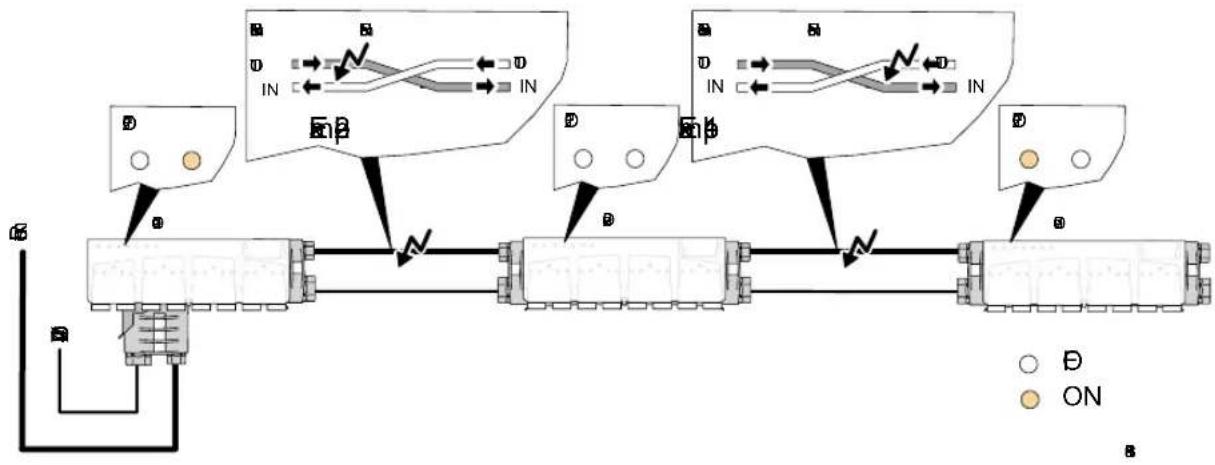
Diagnostic Indicators FO1 to FO3
For modules with optical fiber connection, diagnose indicators FO1 to FO3 indicate at which interface (incoming/outgoing/branching) the transmission is not optimal and also whether the forward data transfer or return data transfer is affected.
flowchart
graph TD
    A["Busbar"] -->|ON| B["Inverter"]
    B -->|B| C["Ground"]
    D["Inverter"] -->|IN| E["Ground"]
    F["Inverter"] -->|IN| G["Ground"]
    H["Ground"] -->|B| I["Inverter"]
    J["Ground"] -->|B| K["Ground"]
Figure 1-7 Diagnostics example using indicators at outgoing interfaces without remote bus branch
Example 1 Figure 1-7
The FO1 LED lights up on device 3.0 if the system reserve has been reached or has been exceeded on the return of the incoming interface.
Example 2 Figure 1-7
The FO2 LED on device 1.0 indicates that the forward path of the outgoing interface is affected.
For the branching interface of a Rugged Line bus terminal module with remote bus branch, the same applies as for the "standard" outgoing interface. The FO3 LED then indicates that the forward path of the branching interface is affected.
1.6 Conversion from Copper to Optical Fiber
1.6.1 Converter for Controller Boards
text_image
Controller board 24 V DC IBS RL 24 BK RB-LK5998B302
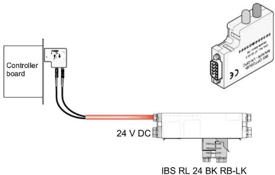
Figure 1-8 IBS OPTOSUB-MA/M/R-LK-OPC
The IBS OPTOSUB-MA/M/R-LK-OPC(-2MBD) module converts the INTERBUS remote interface to polymer fiber.
An INTERBUS controller board can be equipped with an optical fiber interface using this converter.
The converter is a bus device, since it is equipped with an INTERBUS protocol chip (IBS SUPI 3 OPC).
Optical diagnostics is implemented for this bus device.
1.6.2 Converter for Rugged Line Modules
natural_image
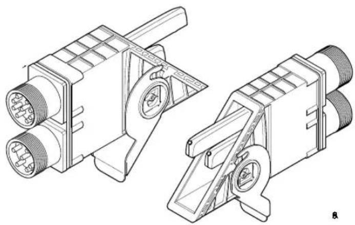
Technical line drawing of two mechanical components with connectors and mounting brackets (no text or symbols)Figure 1-9 Converter
There are two converters for Rugged Line modules with optical fiber connection, which convert the incoming or outgoing bus from copper cables to optical fiber.
- IBS RL 24 ADAP T/LK
This connector converts the incoming remote bus using copper cables to an outgoing remote bus using fiber optics.
- IBS RL 24 ADAP-LK/T
This connector converts the outgoing remote bus using copper cables to an incoming remote bus using fiber optics.
Features
- IP 67 protection
- Connection of the incoming remote bus and the voltage supply of the bus logic and the sensors using 9-pos. circular connectors
- Connection of the actuator supply and voltage supply of the bus logic using 6-pos. circular connectors
Section 2
This section informs you about
– mounting the electronics module and the mounting plate,
- connecting the supply voltage,
- connecting the bus using copper or optical fibers
- connecting the sensors and actuators.
Mounting and Installation....2-3
2.1 Mounting Distances....2-3
2.2 Housing Dimensions 2-4
2.2.1 Dimensions of Bus Terminal Modules 2-4
2.2.2 Dimensions of I/O Modules....2-5
2.2.3 Dimensions of Modules With 4-Slot Housing......2-6
2.3 Attaching the Mounting Plate 2-7
2.4 Mounting the Electronics Module....2-8
2.5 Connecting the Supply Voltage....2-10
2.5.1 Measuring the Supply Voltage....2-13
2.5.2 Diagnostics of the Supply Voltage 2-14
2.6 Connecting the Bus (Copper)....2-15
2.6.1 Sealing Unused Remote Bus Connections....2-18
2.7 Connecting the Bus (Optical Fiber)....2-19
2.7.1 Sealing Unused Remote Bus Connections....2-22
2.8 Mounting Bus Connectors....2-23
2.9 Connecting Sensors/Actuators....2-25
2 Mounting and Installation
Installation options:
– Directly on the welding robot
- On aluminum mounting channels
- Two-position attachment
- Direct mounting
2.1 Mounting Distances
For cabling, a distance must be maintained in the connector area, which is dependent on the minimum bending radius of the cable type used (see "Cable Specifications" on page 6-7).

text_image
Rₘ RₘFigure 2-1 Bending radius (example)

The bus cable, that is pre-assembled by the user, must be at least 1 meter (3.281 ft.). For shorter paths only use cable jumpers from Phoenix Contact (IBS RL CONNECTION..., see "Ordering Data for Accessories" on page 6-15).
2.2 Housing Dimensions
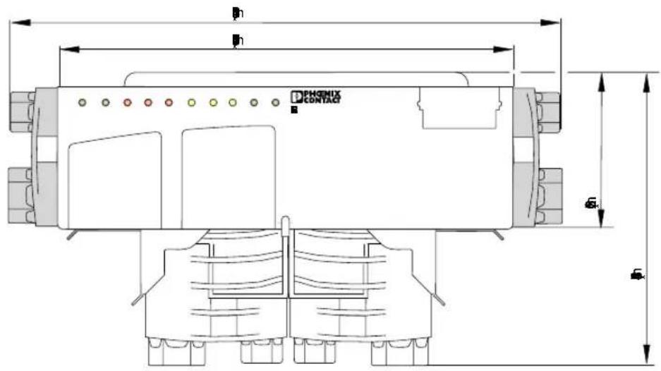
2.2.1 Dimensions of Bus Terminal Modules
text_image
PHGIX CONTACT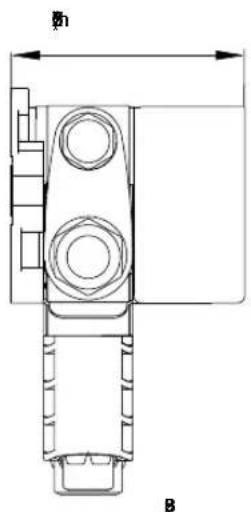
text_image
φ1 BFigure 2-2 Dimensions of bus terminal modules
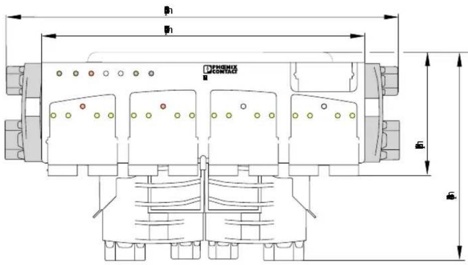
2.2.2 Dimensions of I/O Modules
text_image
PHOENIX CONTACT Φ1 Φ2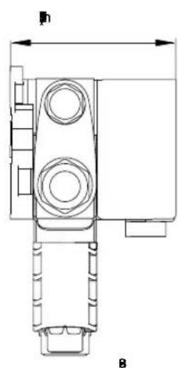
natural_image
Technical line drawing of a mechanical component with no visible text or symbolsFigure 2-3 Dimensions of I/O modules
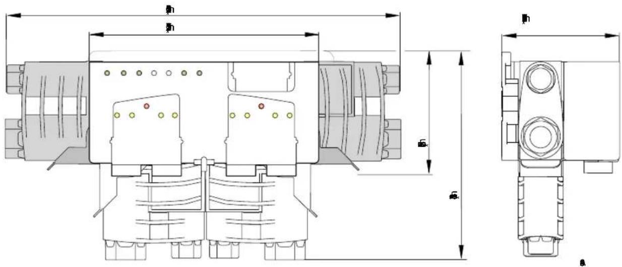
2.2.3 Dimensions of Modules With 4-Slot Housing
text_image
Technical schematic diagram of a mechanical or electrical component with dimension annotations in millimetersFigure 2-4 Dimensions of modules with 4-slot housing

The reversing-load motor starter (IBS RL 400 MLR R DIO6/1-LK2MBD) and the relay module (IBS RL 24 DIO 8/8/8 RS-LK-2MBD) will not be considered in this user manual. Information on these modules can be found in the module-specific data sheets (see Section "Ordering Data for Documentation" on page 6-19).
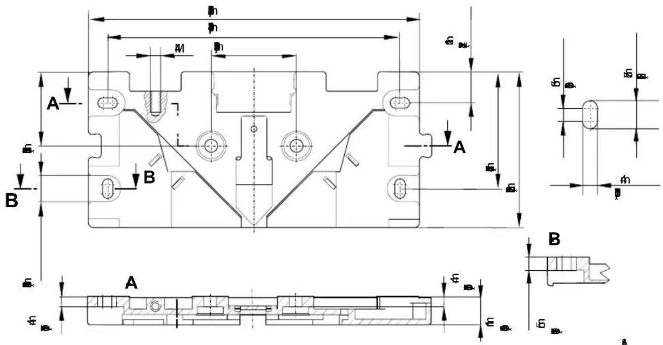
2.3 Attaching the Mounting Plate

The mounting surface must be flat to avoid strain on the module.
Use DIN 84-M4 x 16-8.8 countersunk screws. These screws do not require extra provisions to protect them from loosening.
• Install the mounting plate on a flat mounting surface and use at least two mounting points that lie opposite each other.
text_image
A B M h h h h A B A φ φ φ φ φ φ φ φ φ φ φ φ φ φ φ φ φ φ φ φ φ φ φ φ φ φ φ φ φ φ φ φ φ φ φ φ φ φ φ φ φ φ φ φ φ φ φ φ φ φ αFigure 2-5 Drill hole distances
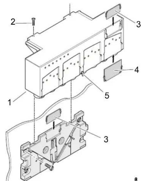
2.4 Mounting the Electronics Module
text_image
Technical diagram of an electrical switch assembly with numbered componentsFigure 2-6 Mounting example
1 Optional functional earth ground connection
2 Mounting screw (according to ISO 4017-M4 x 10-8.8)
3 Labeling field for module designation
4 Labeling field for I/O designation
5 Button to release the electronics module
Mounting

- Place the electronics module on the mounting plate.
- Push the electronics module into the triangular depression of the mounting plate until it snaps into place on the spring.
If the module is used in an environment with a high degree of vibrations you must tighten the electronics module on the mounting plate with an ISO 4017-M4 x 10-8.8 screw (2). This screw does not require additional securing.
Removal
- Press the module down gently (i.e., deeper into the depression of the mounting plate) and then press the button (5).
- Keep the button pressed down.
- Pull the module upwards (in the indicated direction).
Marking For module labeling, you can use labeling fields (3 and 4).
You can use label (3) to label the mounting plate and the module. With label (4) you can label the inputs and outputs.
The labeling fields are not supplied as standard. You can order the labeling fields in a set of 50 pcs. (IBS RL MARKER-SET).
- Push the labeling fields (3 and 4) into the corresponding recesses.
Grounding Optional Functional Earth Ground Connection (1 in Figure 2-6)
If the module is used in environments with heavy noise, you can connect a cable directly to the functional earth ground connection on the module. Note that current loops can occur.
2.5 Connecting the Supply Voltage
text_image
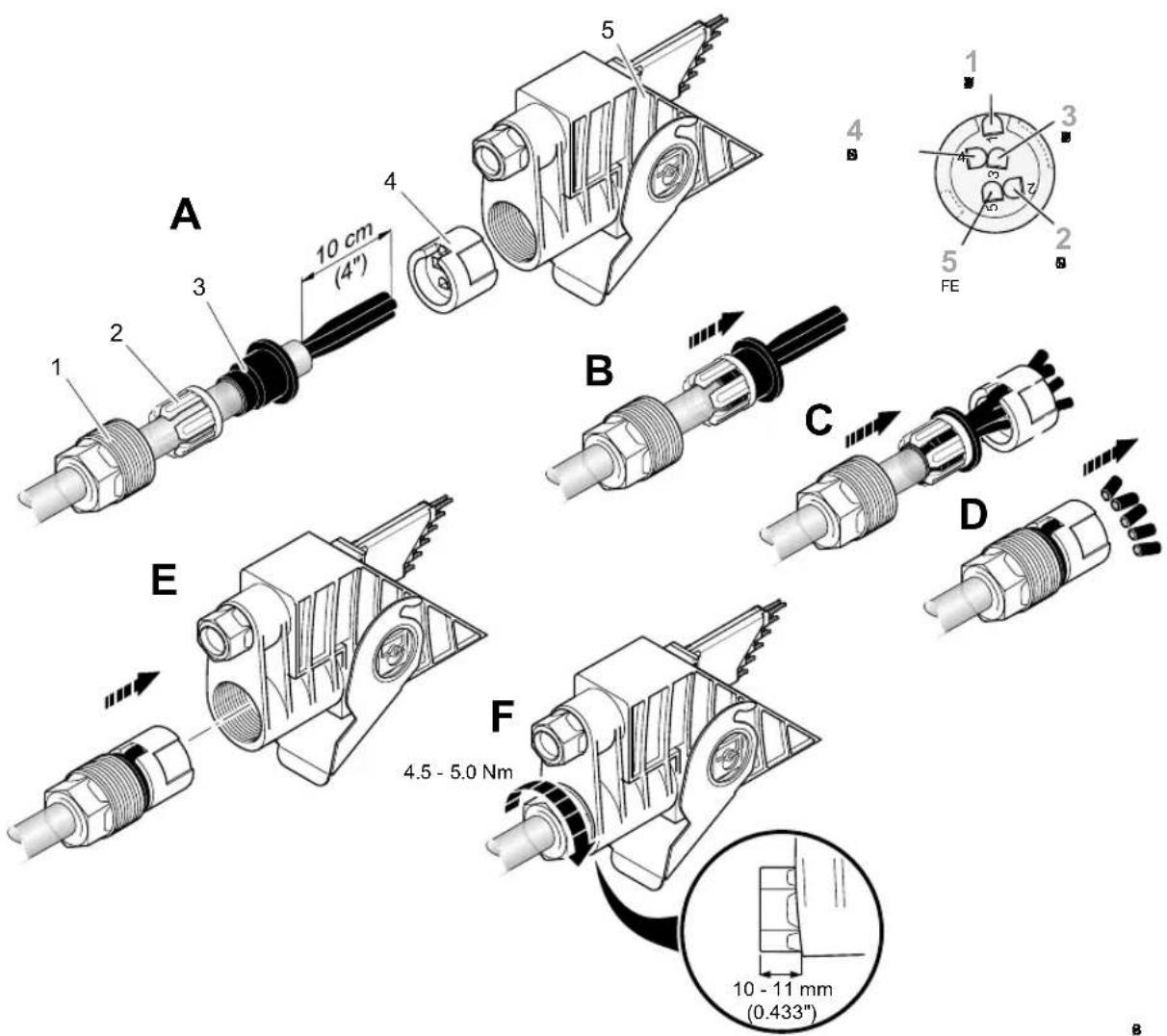
A 10 cm (4") 2 3 4 5 4 1 3 2 5 FE B C D E 4.5 - 5.0 Nm F 10 - 11 mm (0.433") BFigure 2-7 Cable assembly (example)
1 QUICKON screw
2 Compression ring
3 Grommet
4 Splice ring (black, square encoded, with color print)
5 Bus connector (in Figure: bus connector for copper cables)
Procedure
- Pierce the membrane of the grommet (3) using a screwdriver.
- Push the QUICKON screw (1), the compression ring (2), and the grommet (3) onto the cable (Figure 2-7, A).
- Strip approximately 10 cm (3.937 in.) off the outer cable sheath.
- First push the grommet to the end of the cable sheath, then push the compression ring onto the grommet (Figure 2-7, B). This provides the strain relief for the cable.
- Insert the wire ends into the splice ring openings (4). The numbers printed on the cable correspond with the numbering on the splice ring (Figure 2-7, C).
Table 2-1 Connector pin assignment of the supply voltage
| Connection | Signal Meaning | Wire | Color | Designation |
| 1 +24 V | U S1 | Supply of bus logic/spensors | Black 1 | |
| 2 | G S1 N | UBlack 2 | ||
| 3 +24 V | U S2 | Supply of actuators | Black 3 | |
| 4 | G S2 N | UBlack 4 | ||
| 5 | FE | Functional earth ground | Yellow | 5 |
- Push the QUICKON screw onto the compression ring and grommet. The splice ring must be pushed onto the grommet.
- Pull firmly on the wire ends.
- Cut off the protruding wire ends. Ensure that the wire ends are flush with the splice ring; they must neither protrude nor be too short (Figure 2-7, D).
- Attach the assembled cable to the appropriate connector (Figure 2-7, E).
- Turn the assembled cable until the coding tabs fit exactly into the guideways
To ensure a good contact, the QUICKON screw must be screwed into the connector until the threads are no longer visible. (The QUICKON screw must protrude 10 mm (0.394 in.) to 11 mm (0.433 in.) out of the connector.)
- Tighten the QUICKON screw with the IB RL FOC tool (Figure 2-7, F). For this, the torque must be between 4.5 Nm and 5.0 Nm.
The insulation is cut open and the electrical contact is established (QUICKON connection method).


If you want to establish a new connection using the same wires, you must cut off the wires ends. Otherwise, the electrical contact cannot be guaranteed.
2.5.1 Measuring the Supply Voltage
Several factors can cause a drop of the supply voltage for bus logic and sensors (cable lengths, connected devices, module type).

When installing the bus system, make sure that voltages U_S1 and U_S2 do not fall below 18.5 V DC.
The voltage value for the connected sensors depends on the sensor type. The sensor voltage is U_S1 minus 1 V.
If, for example, the sensor requires 20V , the voltage U_S1 must be at least 21V .
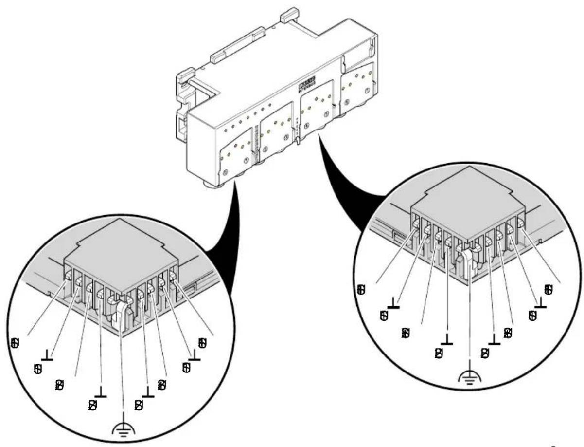
text_image
Technical diagram showing a device connected to a base station, with close-up insets illustrating the structural components.Figure 2-8 Measuring the supply voltage
Measuring the supply voltage
The bus system must be running for measuring to take place. Ideally, all required inputs/outputs of the bus are set when testing the maximum load.
- Connect the measuring instrument to the unused remote bus connection (US1 / US2) of the outgoing remote bus.
If the voltage falls below the required value, it must be boosted.
2.5.2 Diagnostics of the Supply Voltage
If supply voltage U_S1 or U_S2 is below the permissible operating voltage range, the status indicator of the corresponding supply voltage will flash.
In addition, an error message is output for U_S1 .
As soon as the error is removed, the module returns to its normal operating state and the error message is automatically deleted on the module.
If the supply voltage of the actuators ( U_S2 ) fails, this is not reported for a controller board with firmware version ≥ 4.40 . It is also not reported if an IBS CMD SWT G4 or PC WORX version, which is ≥ 4.50 , is used.
2.6 Connecting the Bus (Copper)
Preparing the Bus Connector and Assembling the Cable
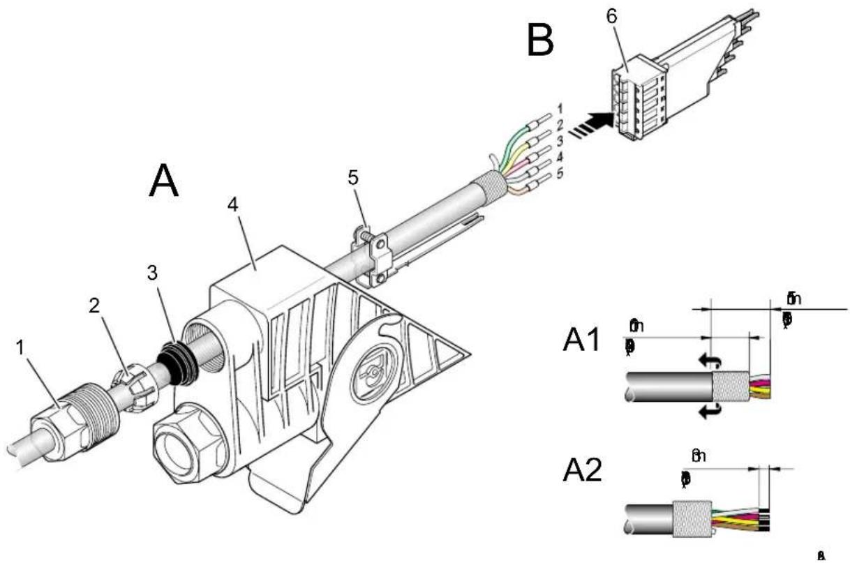
text_image
A B 1 2 3 4 5 6 A1 A2Figure 2-9 Preparing the bus connector
1 QUICKON screw
4 Bus connector
2 Compression ring 5 Clamp
3 Grommet
6 Contact insert
- Pierce the membrane of the grommet (3) using a screwdriver.
- Push the QUICKON screw (1), the compression ring (2), and the grommet (3) onto the remote bus cable (Figure 2-9, A).
- Push the cable through the smaller of the two openings in the bus connector (4).
-
Push the clamp (5) onto the cable.
-
Strip 15 mm (0.591 in.) off the outer cable sheath (Figure 2-9, A1).
- Fold the braided shield (uniformly) back over the cable sheath.
- Strip approximately 3 mm (0.118 in.) off the individual wires (Figure 2-9, A2).
- Cut off the white wire as it is not required.
- Crimp ferrules to the ends of the wires.
- Place the individual wires in the contact insert (6) (Figure 2-9, B).
Table 2-2 Connector pin assignment of the remote bus connection
| Signal Connection Wire Color Designation | |||
| /DO 1 Green GN | |||
| DO 2 Yellow YE | |||
| /DI 3 Pink | PK | ||
| DI 4 | Gray | GY | |
| GND | 5 | Brown BN | |
Connecting the Contact Insert
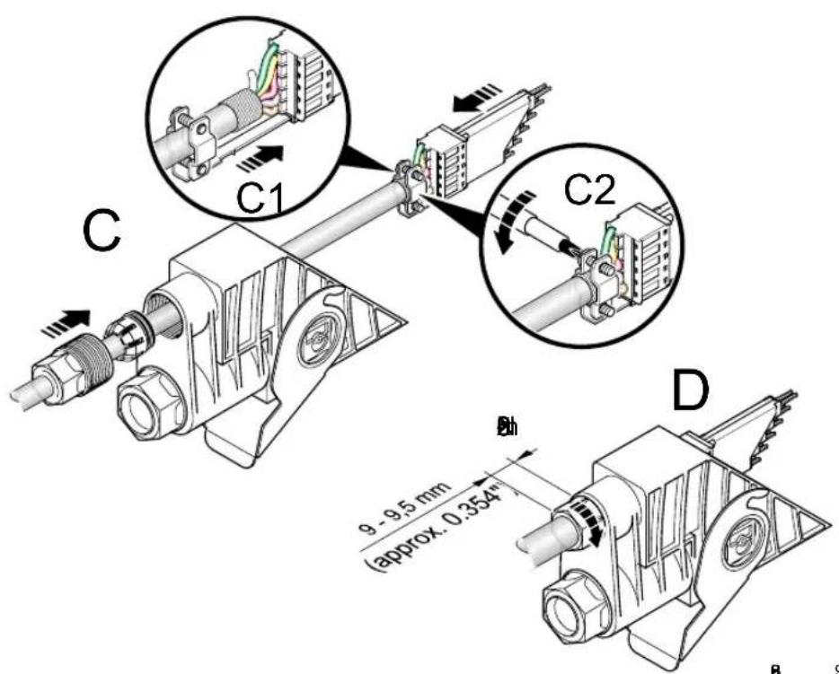
text_image
C C1 C2 D 9 - 9.5 mm (approx. 0.354" BhFigure 2-10 Connecting the contact insert
- Push the clamp over the braided shield and into the contact insert. To ensure shielding, the clamp must be installed directly on the braided shield (Figure 2-10, C1).
- Tighten the screws of the clamp (Figure 2-10, C2).
- Slide the contact insert into the bus connector.
- Push the compression ring onto the grommet, and then push both parts together with the QUICKON screw onto the opening of the bus connector (Figure 2-10, C).
- Tighten the QUICKON screw with the IBS RL FOC tool (Figure 2-10, D). For this, the torque must be between 2.5 Nm and 3 Nm. (The QUICKON screw must protrude 9 mm (0.354 in.) to 10 mm (0.394 in.) out of the connector.)
This ensures IP 67 protection and strain relief of the cable.
2.6.1 Sealing Unused Remote Bus Connections

Do not pierce the grommets of connections that should not be used. Otherwise, IP 67 protection cannot be ensured.
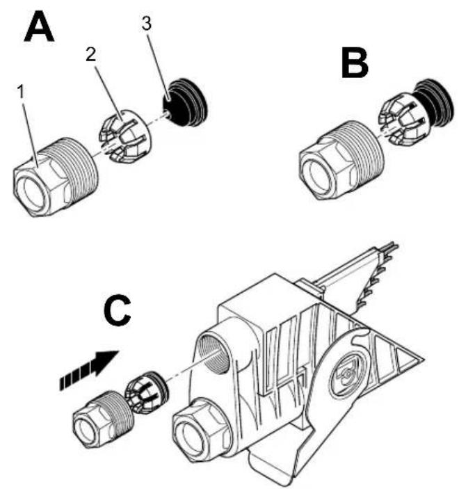
Figure 2-11 Bus connection using copper cables
1 QUICKON screw
2 Compression ring
3 Grommet
Assembly steps
- Push the compression ring (2) onto the grommet (3) (Figure 2-11, B).
- Once assembled, push these into the QUICKON screw (Figure 2-11, C).
- Attach the threaded joint and tighten the QUICKON screw (1) with the IBS RL FOC tool. For this, the torque must be between 4.5 Nm and 5 Nm. (The QUICKON screw must protrude 10 mm (0.394 in.) to 11 mm (0.433 in.) out of the connector.)
2.7 Connecting the Bus (Optical Fiber)

Observe the Optical Fiber Installation Guidelines during the entire installation (see Section "Ordering Data for Documentation" on page 6-19).
Stripping the Outer Sheath
text_image
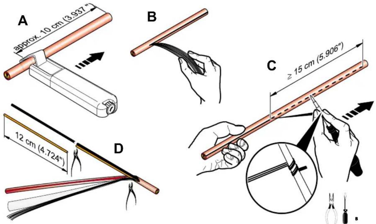
A approx. 10 cm (3.937") B C ≥ 15 cm (5.906") D 12 cm (4.724)Figure 2-12 Stripping the outer sheath

To strip off the cable sheath only use the method described below.
- The cable must be cut lengthways. Position the cable diameter in such a way that the cable is cut along the tearing wire.
- Place the stripping tool (KAMES LWL) on the cable sheath approximately 10 cm (3.937 in.) away from the cable end. Pull the stripping tool lengthways. (Figure 2-12, A)
- If necessary repeat this step until the cable sheath is cut open.
- Remove the tearing wire from the open outer sheath. (Figure 2-12, B)
- Twist the tearing wire around a supporting tool (e.g., screwdriver, pliers) and make sure it is secure (Figure 2-12, C).
- Use the tearing wire to tear open approximately another 15 cm (5.906 in.) of the outer sheath without bending the cable.

The two single conductors must not be damaged.
- Cut off the outer sheath, the strain relief and filler element at the beginning of the slit area using a sharp diagonal cutter without damaging the two single conductors (Figure 2-12, D).
- Shorten the single conductors by 12 cm (4.724 in.) as this part can be damaged through the stripping of the cable with the cable knife.
Connecting Optical Fibers
text_image
A 1 2 3 4 A1 Remote OUT Remote IN C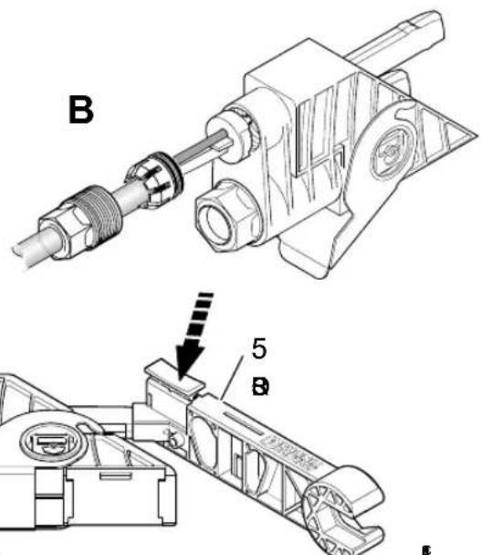
text_image
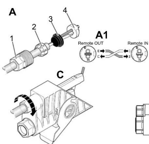
B 5 B EFigure 2-13 Connecting optical fibers
1 QUICKON screw
4 Splice ring (black, with color print)
2 Compression ring
5 IBS RL FOC tool
3 Grommet

- Pierce the membrane of the grommet (3) using a screwdriver.
- Push the QUICKON screw (1), the compression ring (2), and the grommet (3) onto the polymer cable. Push the grommet to the edge of the insulation (Figure 2-13, A).
Note the IN/OUT marking of the splice ring. Cross the individual wires on the opposite splice ring (see Figure 2-13, A1).
- Push the two individual wires through the splice ring. The colored side of the splice ring must show towards the cable. If the individual wires are flush with the splice ring, it is easier to fit the splice ring in the bus connector.
- Insert the two individual wires into the opening of the bus connector and push them until they emerge out the other side (Figure 2-13, B).
Ensure that the encoding of the splice ring fits into the recesses of the bus connector.

Use a torque spanner to tighten the QUICKON screw. The torque must be 3 Nm. A connection that is too tight can lead to a long-term decline in the transmission power.
- Tighten the QUICKON screw with a torque of 3 Nm. The compression creates strain relief (Figure 2-13, C).
- Push the IBS RL FOC tool as far as possible onto the bus connector ensuring that it is flush with the protruding wires (Figure 2-13, D).
• Cut the individual wires using the IBS RL FOC tool. - The connection should be checked for security (see Section "Checking the Optical Fiber Connection" on page 3-14).
2.7.1 Sealing Unused Remote Bus Connections
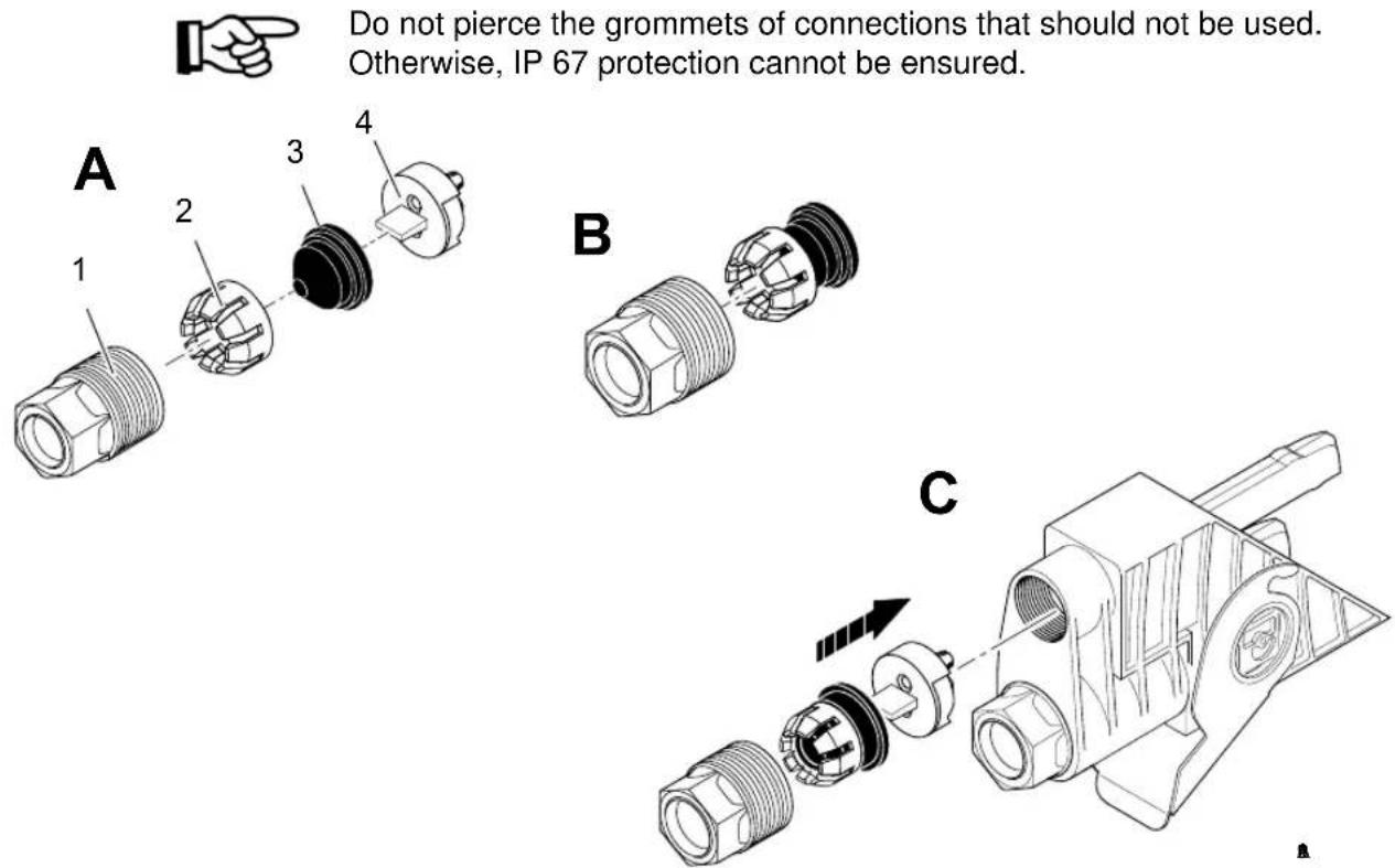
Do not pierce the grommets of connections that should not be used. Otherwise, IP 67 protection cannot be ensured.
Figure 2-14 Bus connection using optical fibers
1 QUICKON screw
2 Compression ring
3 Grommet
4 Splice ring (black, with color print)
Assembly steps
- Push the compression ring (2) onto the grommet (3) (Figure 2-14, B).
- Once assembled, push these into the QUICKON screw (1) (Figure 2-14, C).
- Tighten the QUICKON screw with the IBS RL FOC tool. For this, the torque must be between 4.5 Nm and 5 Nm. The QUICKON screw must protrude 10 mm (0.394 in.) to 11 mm (0.433 in.) out of the connector.
2.8 Mounting Bus Connectors
I/O module bus connectors can be connected to the module in four different ways. In total there are eight possible ways to mount the bus connectors for bus terminal modules with remote bus branch (see Figure 2-15).
The bus connector should only be mounted if the power is switched off.

The lever of the bus connector must not be used to pull the connector into position.
Mounting bus connectors
- Switch the power off.
- Open the lever and insert the connector sufficiently deep into the electronics module (Figure 2-15, A).
- Close the lever (Figure 2-15, B).
Removing bus connectors
- Switch the power off.
Open the lever and remove the connector from the module by pulling in the direction of the cable.
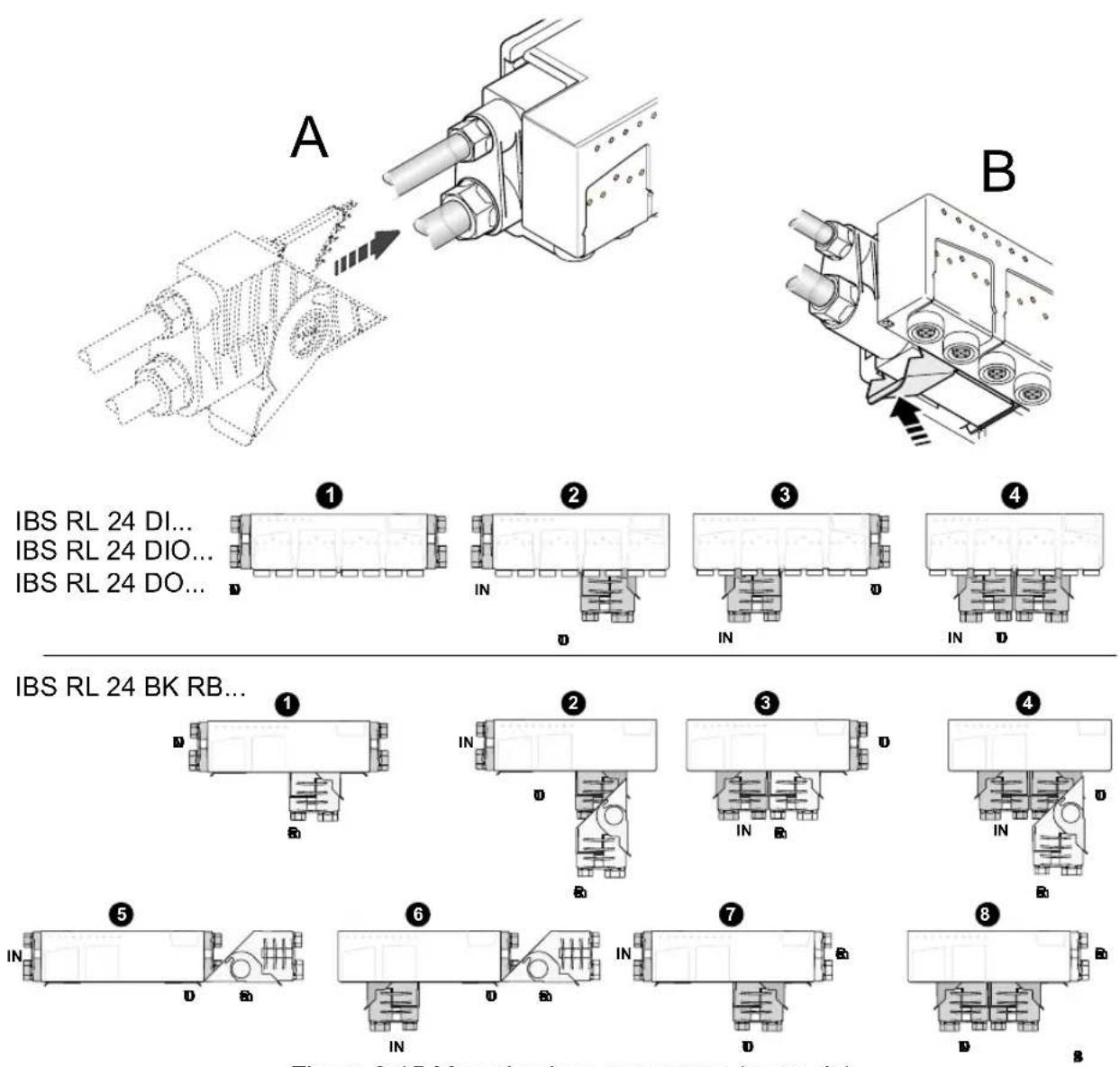
Figure 2-15 Mounting bus connectors (example)
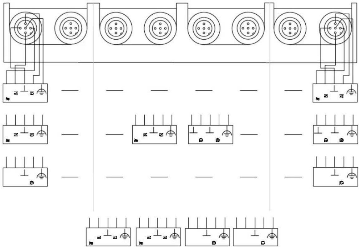
2.9 Connecting Sensors/Actuators

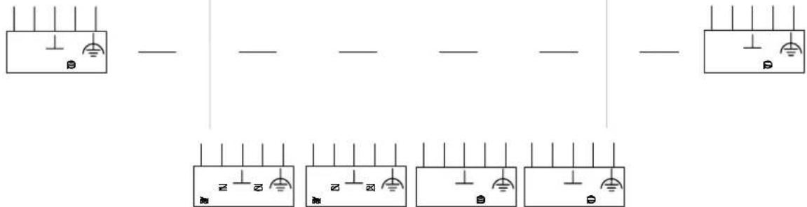
For the pin assignment please refer to the module-specific data sheets.

The sensors and actuators are connected via 5-pos. M12 connectors.
The sensors and actuators must be connected using 3-wire technology.
D
text_image
Electrical wiring diagram showing multiple connection points with labeled terminals (N, B) and grounding symbolsB

text_image
Electrical circuit diagram showing multiple configurations of switches and meters with Chinese labelsB
text_image
Electrical wiring diagram showing three-phase power distribution with grounding symbols and terminal connectionsFigure 2-16 Pin assignment of 5-pos. M12 sockets

A concurrent channel derating of 50% applies to the outputs. This means that only half of all the outputs available per module are allowed to carry the nominal current at any time.
Section 3
This section informs you about
– the operation of Rugged Line modules with an optical fiber connection.
Bus Operation Using Optical Fibers 3-3
3.1 Connecting Optical Fibers....3-3
3.2 Optical Diagnostics ....3-3
3.3 Startup....3-5
3.3.1 Preparation 3-5
3.3.2 Steps for Startup Using Auto Debug....3-6
3.4 Checking the Optical Fiber Connection....3-14
3.4.1 Procedure for Checking the Optical Fiber Connection....3-14
3.4.2 Measuring an Optical Fiber Path ....3-15
3.4.3 Measuring All Paths of an INTERBUS System......3-16
3 Bus Operation Using Optical Fibers
3.1 Connecting Optical Fibers

Connect the optical fibers according to the specifications in Section "Connecting the Bus (Optical Fiber)" on page 2-19.
Observe the Optical Fiber Installation Guidelines during the entire installation (Section "Ordering Data for Documentation" on page 6-19).
3.2 Optical Diagnostics
Rugged Line modules with an optical fiber connection are equipped with an INTERBUS protocol chip (IBS SUPI 3 OPC), which enables improved diagnostics of optical fiber paths.
Optical diagnostics is only possible between two devices that both have an INTERBUS protocol chip SUPI 3 OPC.
Devices with another protocol chip can also be connected between devices with SUPI 3 OPC. However, optical diagnostics does not operate between a device with SUPI 3 OPC and a device with another protocol chip.
Table 3-1 INTERBUS devices with SUPI 3 OPC
| Product Family Designation Order No. | ||
| Rugged Line IBS | RL 24 BK RB-LK-LK 27 25 02 4 | |
| IBS RL 24 DI 16/8-LK 27 24 85 0 | ||
| IBS RL 24 DIO 8/8/8-LK 27 24 84 7 | ||
| IBS RL 24 DO 8/8-2A-LK 27 31 03 4 | ||
| IBS RL 24 BK RB-LK-LK-2MBD 27 31 | 59 7 | |
| IBS RL 24 OC-LK 28 19 97 2 | ||
| IBS RL 24 OC-LK-2MBD 27 32 49 9 | ||
| IBS RL 24 DI 16/8-LK-2MBD | 27 31 58 4 | |
| IBS RL 24 DIO 8/8/8-LK-2MBD | 27 31 57 1 | |
| IBS RL 24 DIO 4/2/4-LK 28 19 98 5 | ||
| IBS RL 24 DIO 4/2/4-LK-2MBD | 27 32 48 6 | |
| IBS RL 24 DIO 8/8/8 RS-LK-2MBD | 27 31 73 3 | |
| IBS RL 400 MLR R-8A DI 4/4-LK-2MBD | 27 31 83 0 | |
| Converters | IBS OPTOSUB-MA/M/R-LK-OPC | 27 32 63 5 |
| IBS OPTOSUB-MA/M/R-LK-OPC-2MBD | 27 31 45 8 | |
| Smart Terminals | IBS ST 24 BKM-LK-OPC | 27 28 66 5 |
| IBS ST 24 BKM-LK-OPC-2MBD | 27 32 50 9 | |

Additional information on optical diagnostics can be found under:
- "Diagnostic and Status Indicators" on page 1-14
- "Startup" on page 3-5
3.3 Startup
When starting up a system using IBS CMD SWT G4 software (version 4.50 or later) supply voltage problems, optical fiber paths with attenuation that is too high and assembly errors can be diagnosed.
Prerequisites

For startup to take place, a mechanically and electrically complete system must be installed.
The following installation concept only operates when INTERBUS devices are used with a uniform transmission rate. A bus configuration of devices with different transmission rates cannot be operated.
3.3.1 Preparation
- Only use Rugged Line modules with a uniform transmission rate.
- Mount and install all modules according to the instructions in Section "Mounting and Installation" on page 2-3.
- Switch on the power supply of the control or computer system.
- Switch on the supply voltage of the Rugged Line modules (U S1 and U S2 ).
The initialization of the bus system now begins.
Initialization During the initialization of an INTERBUS module the system checks
whether another device follows or not. Subsequent devices are automatically detected for the Rugged Line product family. Unlike other INTERBUS product families, a Next/End switch, for example, is no longer required.
If a device is connected to a Rugged Line module, the outgoing interface remains open. If no other device is detected, the interface is closed.
Initialization of a Rugged Line module only occurs, for example, when the module is first connected to the power.
If the bus cable assembly is incorrect, a subsequent device may not be detected. After removing the error, the module must be initialized again, so that the device is detected. For this there is the auto debug mode in the firmware of the controller board, which triggers the initialization process cyclically, until the entire bus is started.
3.3.2 Steps for Startup Using Auto Debug
Step 1 Check the Supply Voltage
- Check whether the US1 LED is lit on each module. If U _S2 is connected the US2 LED must also light up.
- If they are not on check the cable assembly of the supply voltage in the bus connector.
- If they are flashing, the supply voltage is not sufficient. In this case, they must be supplied again.
Auto debug mode can be started using controller boards of Generation 4 with display or using IBS CMD SWT G4 software.
Step 2 Activate Auto Debug Mode
- Auto debug mode can only be activated in the READY state. To reach the READY state, start up the controller board without memory card or trigger an alarm stop via the CMD software.
- Use the display of your controller board or show the display with the keypad in CMD.
Select the item: "IBS DSC display". Display the keypad using the context menu of the display. To do this, place the mouse pointer on the display and press the right mouse button. Select the item: "Panel" from the menu.
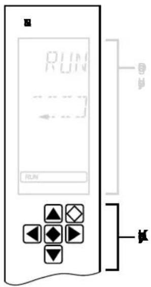
text_image
RUN RUN
UB

DOWN arrow

RIGHT arrow, used to select a menu item or an address

LEFT arrow, used to select a menu item or an address

ENTER, used to accept the selection

ESCAPE, used to quit a menu item, or to move up to the next level
Figure 3-1 Keypad
- Select auto debug mode using the keypad.
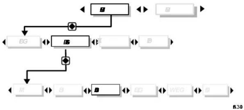
flowchart
graph TD
    A["Start"] --> B["BG"]
    B --> C["DG"]
    C --> D["WEG"]
    D --> E["End"]
    C --> F["Feedback Loop"]
    F --> G["Back to BG"]
    G --> H["Back to DG"]
    H --> I["Back to WEG"]
    I --> J["Back to E"]
    style A fill:#f9f,stroke:#333
    style J fill:#f9f,stroke:#333
Figure 3-2 Menu structure
Step 3 Check the Number of Devices
Auto debug mode is started. The number of devices is shown in the display.
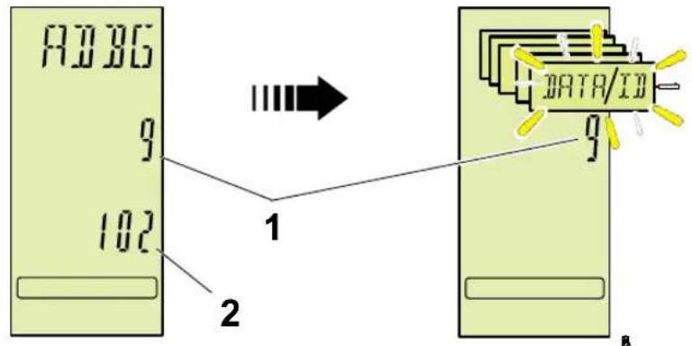
text_image
A3B3G 9 102 1 2 DATA/ID 9 RFigure 3-3 Display
1 Number of devices
2 ID code of the last device
Procedure
- Check whether the actual number of devices corresponds to the number displayed.
If they do not correspond, the devices must be checked using the diagnostic and status indicators.
Check the Diagnostic and Status Indicators of the Devices in Auto Debug Mode
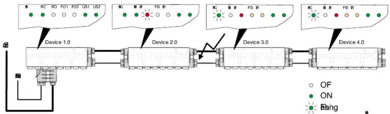
- Check the diagnostic and status indicators.
flowchart
graph LR
    A["Device 1.0"] --> B["Device 2.0"]
    B --> C["Device 3.0"]
    C --> D["Device 4.0"]
    style A fill:#f9f,stroke:#333
    style B fill:#ccf,stroke:#333
    style C fill:#cfc,stroke:#333
    style D fill:#fcc,stroke:#333
Figure 3-4 Example of a bus configuration with errors
In auto debug mode, the red "RD" indicator always flashes on the last device in the branch, since the outgoing interface is tested in each cycle to determine whether a subsequent device is present.
If the "RC" indicator is not lit on a device and the red "RD" indicator is flashing on the previous device, this means that the forward transmission path between the devices is not OK.
In the example, the transmission path between devices 2.0 and 3.0 is affected.
Possible causes are:
- Error in the cable assembly of the bus connector
- Permissible cable length has been exceeded (over 50 m [164.042 ft.] or 35 m [114.829 ft.])
– Squeezing of an optical fiber
Error-Free Bus Configuration in Auto Debug Mode

flowchart
graph LR
    A["Device 1.0"] --> B["Device 2.0"]
    B --> C["Device 3.0"]
    C --> D["Device 4.0"]
    style A fill:#f9f,stroke:#333
    style B fill:#ccf,stroke:#333
    style C fill:#cfc,stroke:#333
    style D fill:#fcc,stroke:#333
Figure 3-5 Example of a bus configuration without errors
In auto debug mode, the red "RD" indicator also flashes on the last device in the branch (device 4.0), since the outgoing interface is tested in each cycle to determine whether a subsequent device is present.
If the bus is running, the quality of the optical fiber installation can be tested.
- Check the state of the "FO1" and "FO2" LEDs on the modules.
The LEDs light up if the optical system reserve limit is reached or exceeded on the optical fiber path. Nevertheless, the bus can be operated without problems.
The path should be structured in such a way that neither of the two LEDs light up.

Step 4 Carrying Out Optical Diagnostics Using CMD

Always carry out optical diagnostics upon inspecting a system and keep the results in an acceptance report.
- Exit auto debug mode. To do this press the ESCAPE button on the keypad of the diagnostic display.
The controller board changes to the READY state. The RDY state is shown on the display.
- Start INTERBUS using the CMD software. Read the configuration frame and execute parameterization.
- Ensure that the bus is running.
- Select menu item "Add-On Programs...Activate" from the "Options" menu.
- Select the "orm.dll" file from the "bin" directory and confirm the selection with "OK".
- Select the "Optical diagnostics" menu item from the controller board context menu.
- Select the "Read In" menu item from the "Optical diagnostics" window.
- Select the "Current Values" menu item to read the current optical diagnostic data.
Values are provided on the path length, optical power levels for forward and return paths and an evaluation of the path quality.
If the values of the optical diagnostics are too poor, the installation and the cable assembly of the corresponding paths must be checked.
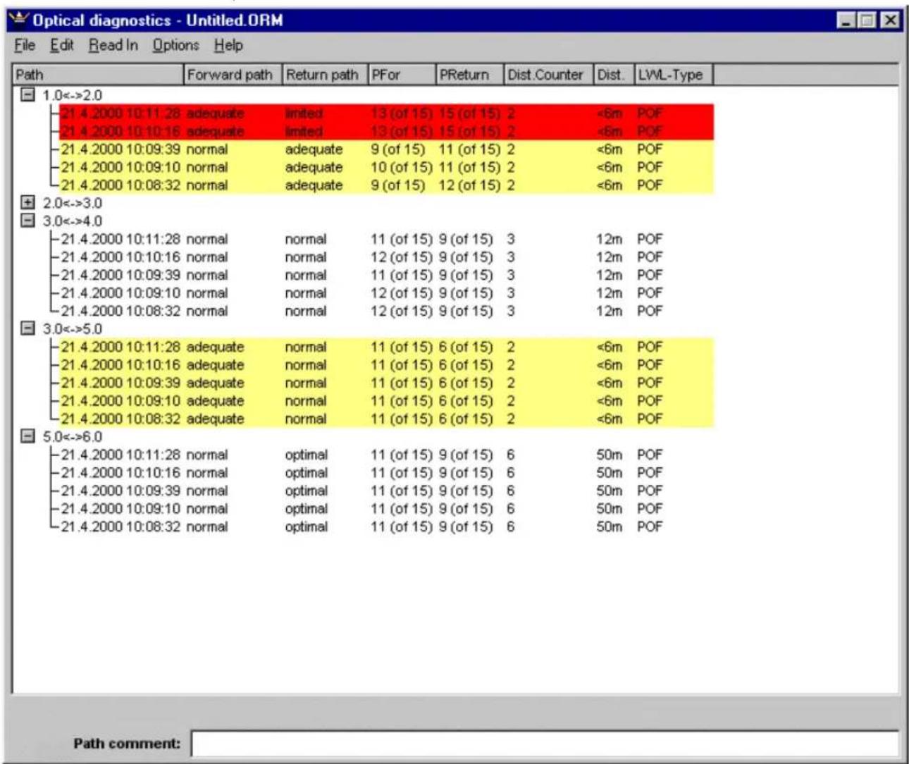
Figure 3-6 Optical diagnostics (CMD version 4.50)
Evaluation
Forward path/Return path
Provides information on the path quality of the forward and return data transfer. The path quality is divided into four levels:
-Optimal
- Normal
- Adequate (yellow)
– Limited (red), i.e., the system reserve has been reached or exceeded.
This state is also shown on the modules using the FO LEDs (see "Diagnostic and Status Indicators" on page 1-14).
Nevertheless, the bus can still operate without problems.
PFor/PReturn Specifies which power level is activated on the forward or return path.
In total there are 15 power levels available for the optical diagnostic system. When the 15th power level is switched, the maximum possible optical power of the interface is reached. Therefore the system reserve is reached or exceeded.
The path quality is determined from the power level and the length of the transmission path. For example, a high power level can produce a "normal" path quality for a very long transmission path, while the same power level can lead to an "adequate" path quality for a short path.
Dist.Counter (Distance counter)
This data is of no significance to the user.
Dist. (Distance)
Specifies the length of the transmission path between the named devices. The accuracy of this data depends on the transmission rate of the devices.
Resolution at:
- 500 kbaud: ±12 m (39.370 ft.)
- 2 Mbaud: ±3 m (9.843 ft.)
LWL-Type (Optical fiber type)
Indicates the cable type, which has been specified for the interface in CMD.
- POF (polymer fiber cable)
- HCS (HCS fiber)
3.4 Checking the Optical Fiber Connection
If problems occur during or after the installation of an optical fiber link, the optical power can be checked before the receiving device using an optical fiber measuring instrument (PSM-FO-POWERMETER). As a rule, this is not necessary, since the INTERBUS system takes over the checking.
3.4.1 Procedure for Checking the Optical Fiber Connection
Interrupt INTERBUS
- Interrupt INTERBUS. No INTERBUS cycles should be running. Remove the bus cable from the control system.
Execute a voltage reset
- Interrupt the module supply voltage and switch it on again so that the module reaches the highest control level.
Prepare the measuring instrument
- Remove a bus connector.
- Clean the optically active area of the measuring instrument PSM-FO-POWERMETER with a clean, lint-free cloth.
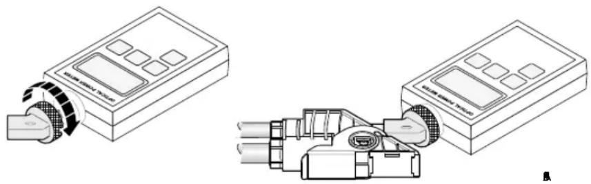
natural_image
Technical line drawings of two electronic devices with ports and connectors, no visible text or symbolsFigure 3-7 Inserting the measuring instrument adapter
- Fasten the IBS RL ADAP-FO adapter to the PSM-FO-POWERMETER measuring instrument.
- Attach the measuring instrument, with the adapter, to the longer of the two remote bus connections for the bus connector.
- Set the measuring instrument to 660 nm.
- Measure the optical power (setting at dBm).
For safe data transmission, the measured level must not exceed -3.6 dBm and it must not drop below -17.0 dBm. This level takes the power drift of the sending and receiving components and a system reserve of 3 dB into account.
3.4.2 Measuring an Optical Fiber Path

flowchart
graph TD
    subgraph_A["Configuration A"]
        A1["INB"] --> A2["R0"]
        A2 --> A3["Device 2.0"]
        A3 --> A4["R20"]
        A4 --> A5["Device 3.0"]
        A5 --> A6["R30"]
    end
    subgraph_B["Configuration B"]
        B1["DC"] --> B2["R1"]
        B2 --> B3["Device 2.0"]
        B3 --> B4["Device 3.0"]
        B4 --> B5["Device 4.0"]
        B5 --> B6["R40"]
    end
Figure 3-8 Measuring the incoming interface of device 2.0

Please observe the notes under "Procedure for Checking the Optical Fiber Connection" on page 3-14.
A Measuring the incoming interface (OUT)
• Supply the voltage back to the outgoing interface.
- Execute a voltage reset.
• Measure the optical power (see Figure 3-8).
B Measuring the incoming interface (IN)
- Disconnect the supply voltage and supply it to the incoming interface.
• Measure the optical power (see Figure 3-8).
3.4.3 Measuring All Paths of an INTERBUS System

Please observe the notes under "Procedure for Checking the Optical Fiber Connection" on page 3-14.
- Disconnect the bus connection to the controller board.
• Prepare the measuring instrument.
Measure the path: INTERBUS IN
- Start all Rugged Line devices, which have a supply voltage, in order. Start with the device to which the voltage is supplied first.
- Check the optical power of the incoming interface at every device.
Measure the path: INTERBUS OUT
To measure the data return path, the Rugged Line devices must be started in reverse order.
- Disconnect the supply voltage and supply it to the last device of the bus segment to be tested.
- Start with the device to which the voltage is now supplied first. Check the optical power of the outgoing interface at every device.
Section 4
This section informs you about
– Rugged Line single channel diagnostics.
Single Channel Diagnostics....4-3
4.1 Enabling Single Channel Diagnostics ....4-3
4.2 Setting the Address for Diagnostic Parameter Register 2......4-5
4.3 Reporting Diagnostic Information....4-7
4.4 Reading Diagnostic Information....4-8
4.5 Assignment of Diagnostic Parameter Register 2 ....4-11
4.6 Acknowledging Error Messages on the Modules......4-12
4.7 Deterioration of Optical Transmission....4-13
4 Single Channel Diagnostics
This chapter explains how single channel diagnostics can be used in your user or control program. Data transmission between the master and the devices is performed using ID cycles. The diagnostic parameter register 2 is used for single channel diagnostics.
4.1 Enabling Single Channel Diagnostics
To use single channel diagnostics, the feature must first be enabled. For this, the two following services must be sent after one another with the INTERBUS system in the READY state.
Service 1
USER DEFINED
Table 4-1 Service 1 (0157 hex)
| Service hex | |
| USER_DEFINED 0157 | |
| Parameter_Count 0003 | |
| Value 4942 | |
| Value 535F | |
| Value 0001 |
Service 2
SET VALUE
REQUEST
Table 4-2 Service 2 (0750 hex)
| Service hex | |
| SET_VALUE_REQUEST | 0750 |
| Parameter_Count 0004 | |
| Variable_Count 0001 | |
| Variable_ID A255 | |
| Value 0000 | |
| Value 04xx | * |
* Variable to enable or inhibit types of errors
It is possible to enable or inhibit individual types of errors by assigning xx (see Table 4-2, "Value"). The effect of different values of xx can be seen in the following table.
| Values of xx Effect | |
| 04_hex | Inhibit all messages |
| 7C_hex | Enable all messages |
| 6C_hex | Only inhibit error messages for the voltage supply U_S2 |

These settings apply to all devices, which support single channel diagnostics and cannot be applied individually to each device.
4.2 Setting the Address for Diagnostic Parameter Register 2
To be able to display the channel number as well as the device number the first time a module error is reported, a second diagnostic parameter register is used for firmware V4.4x or later.
By default this is in the MPM at address 0x37E6 and can also be stored in the I/O area using the "Set value" service (Variable_ID 0x010C) (see "SET_VALUE" on page 4-6).

Please note that in diagnostic parameter register 2, the data can only be updated after the "Confirm_Diagnostics_Request" service has been sent (0760 _hex ).
Only one error message is specified at a time. When sending this service, the existing error messages are shown in the order in which they occurred. The error messages, which now no longer exist and are not displayed, are lost.
- Request the complete error description using the "Read-Cfg-Req-Code" service (0309 _hex ) (see Table 4-7 on page 4-8).
The value of diagnostic parameter register 2 can also be determined via the "Read Value" service using the Variable_ID 0x010D.
The syntax of the services
1 "Set value" service
2 "Read value" service
is described in the following.
SET\_VALUE
Table 4-3 Request: SET_VALUE_REQUEST
| SET_VALUE_REQUEST (750 hex) hex | |
| 0 Parameter_Count 0003 | |
| 1 Variable_Count 0001 | |
| 2 Variable_ID 010C | |
| 3 Value xxxx | * |
* xxxx = address to be assigned, which can be between 1000_hex and 2000_hex
READ\_VALUE
Table 4-4 Request: READ_VALUE_REQUEST
| READ_VALUE_REQUEST (351hex) hex | ||
| 0 Parameter_Count 0002 | ||
| 1 Variable_Count 0001 | ||
| 2 Variable_ID 010D | ||
When the read value request service has been executed, the following service is returned as the response:
Table 4-5 Confirmation result (+): READ_CFG_CNF_CODE
| READ_CFG_CNF_CODE (8351 _hex ) hex | ||
| 0 Parameter_Count 0004 | ||
| 1 Result (+) | 0000 | |
| 1 Variable_Count 0001 | ||
| 2 Variable_ID 010D | ||
| 3 Value xxxx | * | |
* xxxx = value of diagnostic parameter register 2 (diagnostic information 1:1 from slave, see "Assignment of Diagnostic Parameter Register 2" on page 4-11)
4.3 Reporting Diagnostic Information
All changes in status are reported as a module status message at the moment the event occurs.
The 8-bit wide diagnostic parameter register is reported 1:1 in the error code.
The mailbox syntax of the module status message DEVICE_STATE_IND_CODE is described in the following.
Table 4-6 Indication: DEVICE_STATE_IND_CODE
| DEVICE_STATE_IND_CODE (5340 _hex ) hex | ||
| 0 Parameter_Count xxxx | ||
| 0 Device state count (10 maximum) 000x | ||
| 0 Device state 1 80RR | ||
| 0 Log device number 1 xxxx | ||
| Device state x* | 80RR | |
| Log device state x xxxx | ||
* Device state x: Error_Class: 80 Error_Code: RR → Diagnostic information 1:1 from slave (see "Assignment of Diagnostic Parameter Register 2" on page 4-11)
4.4 Reading Diagnostic Information
The module status messages are stored in the extended module status information in the configuration frame. They can be read by the user program from the configuration frame. They cannot be write accessed and are pre-initialized with zeros upon creation of a new configuration frame.
The extended module status information for disconnected devices is also initialized again.
The extended module status information can be read using the "Read configuration" command. This read access to the configuration frame can be controlled using the "Used attributes" parameter.
All extended module information is read by setting bit 11 in the "Used attributes" parameter.
The "Read cfg req code" service has the following mailbox syntax:
READ_CFG_REQ_CODE
Table 4-7 Request: READ_CFG_REQ_CODE
| READ_CFG_REQ_CODE (0309 _hex ) hex | ||
| 0 Parameter_Count 0004 | ||
| 1 Frame_Ref 0001 (typ.) | ||
| 2 Used_Attributes 0800 | ||
| 3 Entry_Number xxxx | ||
| 4 Entry_Count xxxx | ||
When the read cfg req code service has been executed, the following service is returned as the response:
Table 4-8 : Confirmation result(+): READ_CFG_CNF_CODE
| READ_CFG_CNF_CODE (8309 _hex ) hex | ||
| 0 Parameter_Count n | ||
| 1 Result(+) 0 | ||
| 2 More_Follows (FALSE=0; TRUE=1) 000x | ||
| 3 Frame_Ref 0001 (typ.) | ||
| 4 Used_Attributes 0800 | ||
| 5 Entry_Number xxxx | ||
| 6 Entry_Count xxxx | ||
| 7 Cfg_Buf xxxx | ||
| n Cfg_Buf xxxx | ||
The master firmware provides an image of the device diagnostic messages in the configuration frame:
When reading the extended module status the "Cfg_Buf" has the following structure:
| Channel status 16 - 31 | |
| Channel status 0 -15 | |
| Sensor supply Voltage | supply |
Bit assignment:
Table 4-9 Channel status 16 - 31:
| 15 | 14 | 13 | 12 | 11 | 10 | 9 | 8 | 7 | 6 | 5 | 4 | 3 | 2 | 1 | 0 |
| K31 | K30 | K29 | K28 | K27 | K26 | K25 | K24 | K23 | K22 | K21 | K20 | K19 | K18 | K17 | K16 |
Table 4-10 Channel status 0 -15
| 15 | 14 | 13 | 12 | 11 | 10 | 9 | 8 | 7 | 6 | 5 | 4 | 3 | 2 | 1 | 0 |
| K15 | K14 | K13 | K12 | K11 | K10 | K9 | K8 | K7 | K6 | K5 | K4 | K3 | K2 | K1 | K0 |
Table 4-11 Channel status 0 - 15:
| 15 14 13 12 11 10 9 8 7 6 5 4 3 2 1 0 | |||||||||||||||
| Sensor supply Voltage supply | |||||||||||||||
| G8 | G7 | G6 | G5 | G4 | G3 | G2 | G1 | - | - | - | - | U4 | U3 | U2 | U1 |
Where:
Bit = 0 → No error
Bit = 1 → Error

In addition, it is possible to read the value of diagnostic parameter register 2 using the "Read value" function. See "Setting the Address for Diagnostic Parameter Register 2" on page 4-5.
4.5 Assignment of Diagnostic Parameter Register 2
Using bits 14 and 15 it is possible to distinguish between channel-specific and group-specific diagnostic messages.
| Binary Code Meaning | |
| 01xx xxxx Channel-specific diagnostic message | |
| 10xx xxxx Group-specific diagnostic message | |
Table 4-12 Channel-specific diagnostic message
| 7 6 | 5 4 3 2 | 1 0 | |||||
| 0 1 | T K K | K K K | Channel number (K) is encoded | ||||

T = 0 Error is removed
T = 1 Error present
Table 4-13 Group-specific diagnostic message
| 7 6 | 5 4 3 | 2 | 1 | 0 | |||
| 1 | 0 | 0 | 0 | G4 | G3 | G2 | G1 |
| 1 | 0 | 0 | 1 | G8 | G7 | G6 | G5 |
| 1 0 | 1 0 U | 4 U3 | U2 U1 |
Sensor supply group 1 to 4
Sensor supply group 5 to 8
Voltage supply
Bit = 0
No error
Bit = 1
Error
With the group-specific diagnostic message, each bit specifies the status of a group.
4.6 Acknowledging Error Messages on the Modules
To simplify the search for errors, error messages on the devices are indicated locally by the diagnostic LEDs (see also 1.5 on page 1-14). This display is stored on the module in a volatile memory and must be acknowledged by the master.
An exception is voltage monitoring, whose LEDs (US1 and US2) only display the current status. This information is not stored on the module and does not have to be acknowledged by the master.
All errors are acknowledged using the "Control device function" service (0714 _hex ).
This service has the following mailbox syntax:
CONTROL_DEVICE_FUNCTION
Table 4-14 CONTROL_DEVICE_FUNCTION_REQUEST (0714 hex)
| CONTROL_DEVICE_FUNCTION_REQUEST(0714hex) | hex | |
| 0 Parameter_Count 0003 | ||
| 1 Device_Function 0004 | ||
| 2 Entry_Count 0000 | ||

For additional information on this service, please refer to the "Firmware Services and Error Messages" User Manual (IBS SYS FW G4 UM E, Order No. 2745185).
4.7 Deterioration of Optical Transmission
If optical transmission begins to deteriorate, an MAU warning is generated by the affected module. By default, this information is not visible in a PLC and must be enabled.
To enable this MAU warning, the device fail indication must first be enabled using the "Set indication" service. This should be done as follows:
SET\_INDICATION
Table 4-15 SET_INDICATION (0152 hex)
| SET_INDICATION (0152hex) | hex | |
| 0 Parameter_Count 0003 | ||
| 1 Enable_Indication 0001 | ||
| 2 Interface SSGI 0002 | ||
| 3 Device fail indication 5340 | ||

This service is described in the "Firmware Services and Error Messages" User Manual (IBS SYS FW G4 UM E, Order No. 27 45 18 5).
- When this service has been sent, a module must be inserted in the application program on the S7, which fetches the message.

This module is described in the S7 Driver Block User Manual (Order No. 2745347).
Section 5
This section informs you about
- INTERBUS software,
- addressing.
INTERBUS Software Configuration....5-3
5.1 INTERBUS Software....5-3
5.1.1 IBS CMD G4 5-4
5.1.2 PC WORX....5-5
5.2 Addressing 5-6
5 INTERBUS Software Configuration
5.1 INTERBUS Software
The programs IBS CMD (for Standard Controller [SC] boards) and IBS PC WORX (for Field Controllers [FC] and Remote Field Controllers [RFC]) are available for the configuration operation and parameterization of your INTERBUS system. With these programs you can configure, program and visualize all devices integrated in the INTERBUS system.
IBS CMD replaces manufacturer-specific user interfaces for the configuration operation, monitoring and diagnostics of field devices. Complex functions are clearly structured and arranged. All devices can be parameterized, operated and diagnosed from a central location.
In addition to CMD functions, PC WORX offers a programming interface according to IEC 61131-3 and as well as the option for process visualization.
IBS CMD is available in different versions for G3 and G4 INTERBUS controller boards. Because INTERBUS Loop 2 can only be operated with firmware version 4.4x or later, it may only be used with G4 controller boards.
PC WORX requires the use of certain G4 controller boards (Field Controllers/Remote Field Controllers). Field Controllers/Remote Field Controllers can only be configured and parameterized using PC WORX. The programs run completely on the Field Controller/Remote Field Controller so that the host PC is free for operation and visualization tasks.
5.1.1 IBS CMD G4
Interactive and control-independent configuration, operation and diagnostics of all connected devices in an INTERBUS system is possible with IBS CMD G4 software.
IBS CMD runs on standard PCs under MS WINDOWS ^® and can be used for a number of INTERBUS controller boards.
The PC is coupled to the controller board through a serial interface (RS-232).
The IBS CMD program is divided into three program parts. These program parts can be operated in the following logical sequence:
Configuration The configuration menu commands in IBS CMD are used to design a complete bus architecture for a system and to configure all the devices connected to INTERBUS. For example, you can add new devices or search for certain devices. Addresses can be assigned to the input/output channels of the bus devices. Single bus segments can be grouped together. It is also possible to test the bus architecture before startup.
Monitoring All of the connected devices can be monitored and influenced by the
"monitor" program extension. During system operation, the I/O states of connected devices can be indicated and output states can be changed. The dialog functions enable a partial startup of the system. For testing single system parts, the entire bus system and the control system do not have to be installed.
Diagnostics
During startup and servicing, the "diagnostics" operating state helps you to localize and eliminate error sources in the system. In this way, a defective bus device can be detected.
During bus operation, you can give qualitative and quantitative statements about the transmission quality of the bus system.

For additional information on the IBS CMD program refer to the IBS CMD SWT G4 UM E User Manual (Order No. 27 22 25 0).
5.1.2 PC WORX
PC WORX software allows you to configure, program and visualize processes.
PC WORX runs under Windows NT ^® version 4.0 and can only be used with Field Controllers (FC) or Remote Field Controllers (RFC). The host PC is only used for operation and visualization as the programs run completely on the Field Controller.
The PC is coupled to the Field Controller through an RS-232 interface or an Ethernet interface.
PC WORX consists of two parts: SYSTEM WORX and PROGRAM WORX. In addition, visualization software with PC WORX drivers can be installed on the PC WORX basic package.
The configuration and programming data (e.g., the user-defined variables) are available to the other program parts through a common database.
SYSTEM WORX The entire INTERBUS system and the connected devices can be configured, parameterized and diagnosed with SYSTEM WORX.
INTERBUS data is not accessed through addresses but through user-defined variables.
PROGRAM WORX PROGRAMWORX is a programming software based on the IEC 61131 standard. This programming software contains five programming languages:
- IL (Instruction List)
- FBD (Function Block Diagram)
- LD (Ladder Diagram)
- ST (Structured Text)
– SFC (Sequential Function Chart)
Visualization You can graphically display the system structure and sequence with visualization software. You can also create a user interface to read and write data during operation.
5.2 Addressing

General information on addressing can be found in the "General Introduction to the INTERBUS System" User Manual
(IBS SYS INTRO G4 UM E, Order No. 27 45 21 1).
For additional information on INTERBUS addressing, please refer to the "INTERBUS Addressing" data sheet
(DB GB IBS SYS ADDRESS, Order No. 90 00 99 0).
Section 6
This section informs you about
– the technical data for the product range,
– the ordering data for the components, accessories and documentation.
Technical Data....6-3
6.1 INTERBUS System Data 6-3
6.2 Cable Lengths (INTERBUS System) 6-4
6.3 Rugged Line Technical Data....6-5
6.4 Conformance With EMC Directive 6-6
6.5 Cable Specifications....6-7
6.5.1 Specified QUICKON Cables (Supply Cables)....6-7
6.5.2 Specification for the Supply Cable....6-8
6.5.3 Specification for the Remote Bus Cable (Copper)......6-10
6.5.4 Specification for the Remote Bus Cable
(Optical Fiber) 6-11
6.6 Technical Data for the Optical Fiber Interface....6-14
6.7 Ordering Data....6-15
6.7.1 Ordering Data for Accessories....6-15
6.7.2 Ordering Data for Components....6-17
6.7.3 Ordering Data for Documentation....6-19
6 Technical Data

The following tables provide standard data. For different values please refer to the module-specific data sheets.
The technical data does not claim to be complete. Technical modifications reserved.
6.1 INTERBUS System Data
| INTERBUS System | |
| Number of I/O points 4096, maximum | |
| Number of data words 256, maximum | |
| Transmission speed 500 kbaud | |
| Transmission reliability CR check | (hamming distance: 4) |
| Protocol EN 50254 | |
| Number of Devices | |
| Total number of bus devices 512, maximum | |
| Number of remote bus devices 254, maximum | |
| Number of PCP devices 62, maximum | |
| Number of remote bus levels 16, maximum | |
6.2 Cable Lengths (INTERBUS System)
| Distances | |
| From the controller board to the last bus terminal module 12.8 km | m, maximum (7.954 mi.) (copper) |
| 80 km, maximum (49.710 mi.) (glass fiber) | |
| From the controller board to the first device 400 m, maximum (1312.336 ft.) (copper) | |
| Between two remote bus devices 400 m, maximum (1312.336 ft.) (copper) | |
| Between two installation remote bus devices 50 m, maximum (164.042 ft.) (copper) | |
| Between bus terminal module and installation remote bus device | 50 m, maximum (164.042 ft.) (copper) |

For the Rugged Line module family, the optical fiber bus cable, that is pre-assembled by the user, must be at least 1 meter (3.281 ft.). For shorter paths only use cable jumpers from Phoenix Contact
(IBS RL CONNECTION..., see "Ordering Data for Accessories" on page 6-15).
6.3 Rugged Line Technical Data
| General Data | |
| Ambient temperature | Operation: 0°C to +55°C (32°F to 131°F)Storage/transport: -25°C to +70°C(-13°F to 158°F) |
| Humidity Operation: 100% | Storage/transport: 95%, no condensation |
| Air pressure Operation: 860 hPa to 1080 hPa (up | to 1500 m [4921 ft.] above sea level)Storage/transport: 660 hPa to 1080 hPa (up to 3500 m [11483 ft.] above sea level) |
| Degree of protection IP 67 (when installed) | Seal unused slots/connections to ensure IP 67 protection. |
| Material Zinc die-cast | Copper and nickel-plated surface |
| Supply Voltage U_S1 (Bus Logic) | |
| Nominal voltage 24 V DC | |
| Permissible range 18.5 V DC to 32 V DC (ripple included) | |
| Ripple 3.6 V | pp |
| Current consumption 120 mA, typical (plus supply current for the sensors if applicable) | |
| Overvoltage protection 35 V (0.5 s) | |
| The voltage U_S1 is looped through and can be tapped off at the connector for the outgoing remote bus. The maximum continuous current is 16 A. | |
| Mechanical Demands | |
| Vibration according to IEC 60068-2-6 Operation: 5g, Criterion 1 | |
| Shock according to IEC 60068-2-27 | 30g, Criterion 1 |
6.4 Conformance With EMC Directive
| Conformance With EMC Directive 89/336/EEC | ||
 This table provides standard data. For different values please refer to the module-specific data sheets. This table provides standard data. For different values please refer to the module-specific data sheets. | ||
| Noise Immunity Test According to EN 50082-2 | ||
| Electrostatic discharge (ESD) EN 61000 | 0-4-2IEC 61000-4-2 | Class 3, Criterion B |
| Electromagnetic fields EN 61000-4-3 | IEC 61000-4-3 | Criterion A, field strength 10 V/m |
| Fast transients (burst) EN 61000-4-4 | IEC 61000-4-4 | Class 4, Criterion B |
| Surge voltage EN 61000-4-5 | IEC 61000-4-5 | Class 2, Criterion B |
| Conducted interference EN 61000-4-6 | IEC 61000-4-6 | Criterion A, test voltage 10 V |
| Noise Immunity Test According to NAMUR NE 21 | ||
| Immunity to interference NAMUR NE 21 | Voltage dips 0 ms | to 20 ms, repeat rate 1 s, Criterion 1 |
| Noise Emission Test According to EN 50081-2 | ||
| Emitted interference EN 55011 Class A, industrial area | ||
6.5 Cable Specifications

Only special cables are suitable for the QUICKON connection method. Only use the cable types listed below. For the approval of other cable types, please contact Phoenix Contact.
6.5.1 Specified QUICKON Cables (Supply Cables)
| QUICKON Cable With 1.5 mm ^2 (16 AWG) Cable Diameter | ||
| Manufacturer Type Properties | ||
| Phoenix Contact IBS PWR/5 | Order No. 28 20 00 0 | Welding-splash-resistant in standard applications |
| Phoenix Contact IBS PWR/5 | HD/FOrder No. 27 31 77 5 | Suitable for use as trailing cable; welding-splash-resistant in standard applications |
6.5.2 Specification for the Supply Cable
| IBS PWR/5 IBS PWR/5 HD/F | ||
| Description Supply cable for QUICKON connection method; welding-splash-resistant in standard applications | Supply cable for QUICKON connection method with high alternating bending strength; welding-splash-resistant in standard applications | |
| Structure Wire: 5 x 1.5 mm | 2 (16 AWG) | |
| Color coding 4 x black, 1 x yellow | ||
| Outer cable sheath | ||
| Material Color Properties | Polyvinyl chloride (PVC) Gray (RAL 7001) Oil-resistant, flame-retardant, welding-splash-resistant in standard applications, suitable for QUICKON connection method | Polyurethane (PUR) Gray (RAL 7040) Halogen-free, torsion capability, PVC-free, oil-resistant, flame-retardant, suitable for use as trailing cable, welding-splash-resistant in standard applications, suitable for QUICKON connection method |
| Single wire Material Polyvinyl chloride (PVC) Polyethylene (PE) | ||
| Bending radii | ||
| Short (permanent installation) Permanent (perm. installation) Flexible installation | - At least 70 mm (2.756 in.) At least 132 mm (5.197 in.) | At least 20 mm (0.787 in.) At least 50 mm (1.969 in.) At least 99 mm (3.898 in.) |
| Temperature range Permanent installation Flexible | -30°C to +80°C (-22°F to +176°F) - | -20°C to +70°C (-4°F to +158°F) -50°C to +70°C (-58°F to +158°F) |
| DC resistance per 1000 m 13.3 | Ω, maximum, for plain single wires 13.7 Ω, maximum, for metal clad single wires | - |
| (Continued) IBS PWR/5 IBS PWR/5 HD/F | ||
| Operating peak voltage 250 V 600 V | ||
| Test voltage; wire/wire 1200 V/DC | 3000 V/DC, 1 minute | (VDE 0472-509 test type C) |
| DiameterOuter cable sheathWire including insulation | 8.8 mm (0.346 in.) ±0.3 mm(0.012 in.)2.5 mm (0.098 in.) | 9.9 mm (0.390 in.)2.8 mm (0.110 in.) |
| Weight Approximately 139 g/m Approximately 130 g/m | ||
| Chloroform test Free of substances which would hinder coating with paint or varnish according to central standard 57650 of VW, Audi and Seat | ||
6.5.3 Specification for the Remote Bus Cable (Copper)
| IBS RBC METER/F-T | |
| Description INTERBUS remote bus cable for harsh environment conditions with high alternating bending strength | |
| Structure Wire: copper wires 0.25 mm ^2 (24 AWG) | |
| Color coding Pink, gray, yellow, green, white, brown | |
| Outer cable sheath Material, color Properties | Polyurethane, green Halogen-free Flame-retardant according to DIN VDE 0472-804, test type B Oil-resistant according to DIN VDE 0472-803, test type B Welding-splash-resistant in standard applications |
| Bending radii Minimum bending radius for permanent movement: 121.5 mm (4.783 in.) | |
| Temperature range Permanent installation Flexible | -30°C to +70°C (-22°F to +158°F) -5°C to +70°C (23°F to +158°F) |
| DC resistance | ≤0.096 Ω/m |
| Operating peak voltage 250 V | |
| Test voltage; wire/wire 1500 V/DC | |
| Insulation resistance | ≤150 MΩ/km |
| Diameter of the outer cable sheath 8.1 mm (0.319 in.) | |
| Weight 74 g/m | |
6.5.4 Specification for the Remote Bus Cable (Optical Fiber)
| Cable Specification: Polymer Fiber | |||
| Polymer Fiber for Permanent Indoor Installation | Polymer Fiber for Permanent Indoor Installation | Polymer Fiber for Flexible Indoor Applications | |
| PSM-LWL-KDHEAVY-980/1000 | PSM-LWL-RUGGED-980/1000 | PSM-LWL-RUGGED-FLEX-980/1000 | |
| Fiber | |||
| Core/cladding diameterRetractive index profileMaterialAttenuation at 650 nmAttenuation at 660 nm | 980 μm/1000 μm,Step indexPMMA≤ 160 dB/km (monochromatic)≤ 230 dB/km (LED) | 980 μm/1000 μmPMMA≤ 160 dB/km (monochromatic)≤ 230 dB/km (LED) | 980 μm/1000 μmPMMA≤ 250 dB/km (monochromatic)≤ 280 dB/km (LED) |
| Single wire | |||
| MaterialColorDiameter | Polyamide (PA)Orange or black2.2 mm (0.087 in.) ± 0.07 mm (0.003 in.) | Polyamide (PA)Orange or black2.2 mm (0.087 in.) ± 0.07 mm (0.003 in.) | Polyamide (PA)Orange or black2.2 mm (0.087 in.) ± 0.07 mm (0.003 in.) |
| Outer cable sheath | |||
| MaterialColorStrain reliefDiameter 6.0 mm (0.236 in.) | Polyurethane (PUR)RedNon-metal,aramide yarn± 0.5 mm (0.020 in.) | Polyurethane (PUR)RedNon-metal,aramide yarn8.0 mm (0.315 in.) ± 0.5 mm (0.020 in.) | Polyurethane (PUR)RedNon-metal,wool fiber8.0 mm (0.315 in.) ± 0.5 mm (0.020 in.) |
| Numerical aperture 0.47 ± 0.03 | 0.47 ± 0.03 | 0.47 ± 0.03 | |
| Bandwidth length product (at 660 nm LED) | >10 MHz * 100 m > | 10 MHz * 100 m >10 MHz * 100 m | |
| Attenuation* | ≤ 230 dB/km ≤ 230 | dB/km < 280 dB/km | |
| Cable Specification: Polymer Fiber (Continued) | |||
| Polymer Fiber for Permanent Indoor Installation | Polymer Fiber for Permanent Indoor Installation | Polymer Fiber for Flexible Indoor Applications | |
| PSM-LWL-KDHEAVY-980/1000 | PSM-LWL-RUGGED-980/1000 | PSM-LWL-RUGGED-FLEX-980/1000 | |
| Temperature range | |||
| Storage | -40°C to +80°C(-40°F to +176°F) | -40°C to +80°C(-40°F to 176°F) | -40°C to +80°C(-40°F to +176°F) |
| Installation | +5°C to +50°C(+41°F to +122°F) | +5°C to +50°C(+41°F to +122°F) | +5°C to +50°C(41°F to +122°F) |
| Operation | -20°C to +70°C(-4°F to +158°F) | -20°C to +70°C(-4°F to +158°F) | -20°C to +70°C(-4°F to +158°F) |
| Weight 28 kg/km 51 kg/km 51 kg/km | |||
| Bending radius (individual wire) | At least 30 mm(1.181 in.) | At least 30 mm(1.181 in.) | At least 30 mm(1.181 in.) |
| Bending radius (cable) | |||
| Short-term | At least 30 mm(1.181 in.) | At least 50 mm(1.969 in.) | At least 50 mm(1.969 in.) |
| Permanent | At least 50 mm(1.969 in.) | At least 65 mm(2.559 in.) | At least 65 mm(2.559 in.) |
| Tensile strength | |||
| Short-term | Up to 600 N | Up to 1000 N | Up to 300 N |
| Permanent | Up to 100 N | Up to 100 N | Up to 100 N |
| Lateral strength | |||
| Short-term | Up to 200 N/cm | Up to 300 N/cm | Up to 200 N/cm |
| Permanent | Up to 20 N/cm | Up to 20 N/cm | Up to 20 N/cm |
| Impact strength 2 Nm/10 impacts,maximum | 2 Nm/10 impacts,maximum | 2 Nm/10 impacts,maximum | |
| Alternating bending ability‡(DIN EN 187000,method 509) | - | - | 10 x0NAt least 50,000 cycles |
| Repeated bending‡(DIN EN 187000, method 507) | - | - | 10 x d, 5 NAt least100,000 cycles |
| Suitable for use as trailing cable‡(PT test instruction F45051-R9019-A) | - | - | 10 x dAt least5 million cycles |
| Resistance to oil | IRM oil No. 2, 100°C (212°F), DIN VDE 0473-811-2-1 | ||
| Free from substances which would hinder coating with paint or varnish | Chloroform test according to central standard 57650 of VW, Audi and Seat | ||
| Free from halogen(DIN VDE 0472-813) | ph value ≥ 4.3Conductivity ≤ 10 μS | ||
| Resistance to ozone DIN VDE 0472-805, test type B | |||
| Resistance to ultraviolet rays | DIN 53387 (method 1, condition A) | ||
| Resistance to abrasion(DIN EN 187000, method 502) | At least 5000 cycles, 1 mm (0.039 in.) radius of the steel needle peak, 500 g | ||
* 50 m (164.042 ft.) long fibers at 25°C (77°F) measured with 660 nm LED source
d = diameter
‡ Criterion: increase of attenuation ≤1 dB
6.6 Technical Data for the Optical Fiber Interface
| Optical Power Level | ||
| Cable type PSM-LWL- | RUGGED-980/1000PSM-LWL-KDHEAVY-980/1000 | PSM-LWL-RUGGED-FLEX-980/1000 |
| Maximum fiber attenuation at 660 nm LED measurement | 230 dB/km 280 dB/km | |
| Typical fiber attenuation at 660 nm LED measurement | 200 dB/km 250 dB/km | |
| Transmission distance* | 50 m, typical 35 m, typical | |
| Minimum transmission distance 1 m (3.281 ft.) 1 m (3.281 ft.) | ||
| Optical output power at 25°C (77°F) | -4.9 dBm, typical | |
| Maximum optical output power at 25°C (77°F) | -2 dBm | |
| Optical output power (0°C to 55°C [32°F to 131°F]) | -5.8 dBm, typical | |
| Minimum optical receiver responsivity (0°C to 55°C [32°F to 131°F]) | -20.6 dBm | |
| Optical overrange at 25°C (77°F) | >-2 dBm | |
| Available attenuation (0°C to 55°C [32°F to 131°F]) | 14.8 dB | |
| Maximum wavelength (0°C to 55°C [32°F to 131°F]) | 660 nm | |
| System reserve | 3 dB | |
| Available attenuation for optical fibers | 11.8 dB | |
* Transmission distances of < 1 m (3.281 ft.) are only permitted with Phoenix Contact's special pre-assembled cable jumper IBS RL CONNECTION-LK.
6.7 Ordering Data
6.7.1 Ordering Data for Accessories
General Accessories
| Description Order Designation Order No. | ||
| Mounting plate IBS RL AP 27 31 12 8 | ||
| Labeling fields (set of 50 pcs.) IBS RL MARKER-SET 27 32 72 9 | ||
| Protective caps (5 pcs.)for unused M12 sockets | IBS IP PROT IO 27 59 91 9 | |
| Supply cable, 5 × 1.5 mm^2 (16 AWG), gray,very flexible, welding-splash-resistant in standard applications | IBS PWR/5HD/F 27 31 77 5 | |
| Supply cable, gray, welding-splash-resistant in standard applications, 5 × 1.5 mm^2 (16 AWG) | IBS PWR/5 28 20 00 0 | |
| Fiber cutter IBS RL FOC 27 25 14 7 | ||
| 4-pos. sensor connector with QUICKON connection for M12 female connectors | SACC-M12MS-4QLCON | 16 40 22 3 |
Accessories for Copper
| Description Order Designation Order No. | ||
| Bus connector (copper) | IBS RL PLUG-T | 27 31 89 8 |
| Remote bus cable for very flexible applications, welding-splash-resistant in standard applications | IBS RBC METER/F-T | 27 23 12 3 |
| Assembled cable jumper for the short connection of the Rugged Line devices with two copper bus connectors (remote bus and supply voltage) | IBS RL CONNECTION-T | 27 33 06 1 |
Accessories for Optical Fibers
| Description Order Designation Order No. | ||
| Bus connector (optical fibers) IBS RL PLUG-LK/POF 27 31 07 6 | ||
| Optical fiber data cable: Polymer fiber cable, duplex, 980/1000 μm, red, welding-splash-resistant in standard applications; sold by the meter, cable is not pre-assembled | PSM-LWL-RUGGED-980/1000 27 44 | 32 2 |
| Optical fiber data cable (flexible): Polymer fiber cable, duplex, 980/1000 μm, dark red, welding-splash-resistant in standard applications; tested for flexible cable tracks, sold by the meter cable is not pre-assembled | PSM-LWL-RUGGED-FLEX-980/1000 | 27 44 33 5 |
| Optical fiber data cable: Polymer fiber cable, duplex, 980/1000 μm, , sold by the meter, not pre-assembled | PSM-LWL-KDHEAVY-980/1000 27 44 | 31 9 |
| Assembled cable jumper for the short connection of the Rugged Line devices with two optical fiber bus connectors (remote bus and supply voltage) | IBS RL CONNECTION-LK 27 33 02 9 | |
| Stripping pliers KAMES LWL 12 06 14 6 | ||
| Adpater for remote bus connection from optical fiber to circular connector | IBS RL 24 ADAP-LK/T 27 25 04 0 | |
| Adpater for remote bus connection from circular connector to optical fiber | IBS RL 24 ADAP T/LK 27 25 03 7 | |
| Adapter for an INTERBUS remote interface (9-pos. D-SUB) to polymer fiber (F-SMA) | IBS OPTOSUB-MA/M/R-LK-OPC 27 | 32 63 5 |
| Adapter for an INTERBUS remote interface (9-pos. D-SUB) to polymer fiber (F-SMA) with a transmission rate of 2 Mbaud | IBS OPTOSUB-MA/M/R-LK-OPC-2MBD | 27 31 45 8 |
| Measuring instrument PSM-FO-POWERMETER | 27 99 53 9 | |
| Measuring instrument adapter IBS RL ADAP FO | 27 25 12 1 | |
| Tool for polymer fiber cable | IBS RL FOC | 27 25 14 7 |
6.7.2 Ordering Data for Components
| Description Order Designation Order No. | ||
| Copper | ||
| Bus terminal module with remote bus branch | IBS RL 24 BK RB-T-T 27 31 06 3 | |
| Digital input module with 16 inputs on eight M12 sockets | IBS RL 24 DI 16/8-T 28 36 46 3 | |
| Digital input/output module with eight inputs and eight outputs on eight M12 sockets | IBS RL 24 DIO 8/8/8-T 28 36 47 6 | |
| Digital output module with eight outputs on eight M12 sockets | IBS RL 24 DO 8/8-2A-T 27 31 85 6 | |
| Fiber Optics | ||
| Bus terminal module with remote bus branch | IBS RL 24 BK RB-LK-LK 27 25 02 4 | |
| Digital input module with 16 inputs on eight M12 sockets | IBS RL 24 DI 16/8-LK 27 24 85 0 | |
| Digital input/output module with eight inputs and eight outputs on eight M12 sockets | IBS RL 24 DIO 8/8/8-LK 27 24 84 7 | |
| Digital output module with eight outputs on eight M12 sockets | IBS RL 24 DO 8/8-2A-LK 27 31 03 4 | |
| Module for segmenting the bus (bus terminal module without remote bus branch with 4-slot housing) | IBS RL 24 OC-LK 28 19 97 2 | |
| Digital input/output module with four inputs and two outputs on four M12 sockets with 4-slot housing | IBS RL 24 DIO 4/2/4-LK 28 19 98 5 | |
| Fiber Optics, 2 Mbaud Transmission Rate | ||
| Bus terminal module with remote bus branch | IBS RL 24 BK RB-LK-LK-2MBD 27 31 59 | 7 |
| Module for segmenting the bus (bus terminal module without remote bus branch with 4-slot housing) | IBS RL 24 OC-LK-2MBD 27 32 49 9 | |
| Digital input module with 16 inputs on eight M12 sockets | IBS RL 24 DI 16/8-LK-2MBD 27 31 58 4 | |
| Digital input/output module with eight inputs and eight outputs on eight M12 sockets | IBS RL 24 DIO 8/8/8-LK-2MBD 27 31 57 1 | |
| Digital input/output module with four inputs and two outputs on four M12 sockets with 4-slot housing | IBS RL 24 DIO 4/2/4-LK-2MBD 27 32 48 6 | |
| Digital I/O module with relay contacts IBS | RL 24 DIO 8/8/8 RS-LK-2MBD 27 31 73 3 | |
| Reversing-load motor starter IBS RL 400 | MLR R-8A DI 4/4-LK-2MBD 27 31 83 0 | |
6.7.3 Ordering Data for Documentation
| Description Order Designation Order No. | ||
| General Introduction to the INTERBUS System | IBS SYS INTRO G4 UM E 27 45 21 1 | |
| Configuring and Installing INTERBUS IBS SYS PRO INST UM E 27 43 80 2 | ||
| CD-ROM with all INTERBUS data sheets CD IBS DB ELDOC 27 45 60 6 | ||
| CD-ROM with all INTERBUS manuals and data sheets | CD IBS UM/DB ELDOC 27 45 61 9 | |
| Optical Fiber Installation Guidelines DB GB IBS SYS FOC ASSEMBLY | 94 23 43 9 | |
| Data sheet for the reversing-load motor starter of the Rugged Line product family | DB GB IBS RL 400 MLR DIO 6/1 LK2MBD | 90 02 86 7 |

Complete INTERBUS documentation is also available on the Internet at http://www.phoenixcontact.com under "InfoService".
A List of Devices for a Rugged Line System
The following tables contain a list of all current Rugged Line devices and their most important features and order numbers.
Short Description The short description gives a brief overview of the module.
This may specify:
– Number of inputs/outputs
- Nominal voltage
- Nominal current
– Any special features
ID code/length code
Every INTERBUS device has an ID code (Identification Code) so that the device can be identified by the controller board. The ID code indicates the device type. In the tables, this code is indicated with decimal and hexadecimal values.
The length code indicates the number and representation format of the process data (bit, nibble, byte, word). In the tables, this code is indicated with decimal and hexadecimal values.
From the ID codes and length codes, the controller board generates a bus image which is used later for address assignment of the I/O data and for error detection during operation.
IN addr. Number of bytes that the module requires in the input address area
The INTERBUS devices store the data for the control system in the input address area.
OUT addr. Number of bytes that the module requires in the output address area
The control system stores the data that is to be transmitted to the INTERBUS devices in the output address area.
Reg. length Number of bytes in the INTERBUS ring (register length) for cycle time calculation
The register length indicates the number of bytes that a device occupies in the INTERBUS ring. This information is required to calculate the cycle time.
Table A-1 Rugged Line device list
| Order Designation | Order No. | Short Description ID Code | Dec/Hex | Length Code Dec/Hex | IN Addr. | OUT Addr. | Reg. Length |
| Bus Terminal Module | |||||||
| IBS RL 24 BK-RB-T-T 27 31 06 3 | Twisted pair | connection500 kbaud transmission rate | 12/0C 00/0 | 0 0 bits 0 | bits 0 bits | ||
| IBS RL 24 BK-RB-LK-LK 27 25 02 | 4 Optical fiber connection500 kbaud transmission rate | 12/0C 00/0 | 0 0 bits 0 | bits 0 bits | |||
| IBS RL 24 BK-RB-LK-LK-2MBD 27 31 59 7 | Optical fiber connection2 Mbaud transmission rate | 12/0C 00/0 | 0 0 bits 0 | bits 0 bits | |||
| Digital Inputs | |||||||
| IBS RL 24 DI 16/8-T 27 36 46 3 16 IN, | twisted pair connection500 kbaud transmission rate | 02/02 01/0 | 1 2 | bytes | 2 bytes | 2 bytes | |
| IBS RL 24 DI 16/8-LK | 27 24 85 0 16 IN,optical fiber connection500 kbaud transmission rate | 02/02 01/0 | 1 2 | bytes | 2 bytes | 2 bytes | |
| IBS RL 24 DI 16/8-LK-2MBD | 27 31 58 4 16 IN,optical fiber connection2 Mbaud transmission rate | 02/02 01/0 | 1 2 | bytes | 2 bytes | 2 bytes | |
| Digital Outputs | |||||||
| IBS RL 24 DO 8/8-T 27 31 85 6 8 | OUT, | twisted pair connection500 kbaud transmission rate | 01/01 129/81 | 1 byte | 1 byte | 1 byte | |
| IBS RL 24 DI 8/8-LK | 27 31 03 4 8 OUT,optical fiber connection500 kbaud transmission rate | 01/01 129/81 | 1 byte | 1 byte | 1 byte | 1 byte | |
| Digital Inputs and Outputs | |||||||
| IBS RL 24 DIO 8/8/8-T | 28 36 47 6 8 IN, 8 OUTtwisted pair connection500 kbaud transmission rate | 03/03 129/81 | 1 byte | 1 byte | 1 byte | 1 byte | |
| IBS RL 24 DIO 8/8/8-LK | 27 24 85 0 8 IN, 8 OUToptical fiber connection500 kbaud transmission rate | 03/03 129/81 | 1 byte | 1 byte | 1 byte | 1 byte | |
| IBS RL 24 DIO 8/8/8-LK-2MBD 27 | 31 57 1 8 IN | , 8 OUT optical fiber connection 2 Mbaud transmission rate | 03/03 129 | 81 1 byte 1 | byte 1 | byte | |
| IBS RL 24 DIO 4/2/4-LK 28 19 98 | 5 4 IN, 2 OUT | optical fiber connection 500 kbaud transmission rate | 03/03 65/4 | 1 1 byte 1 | byte 1 | byte | |
| IBS RL 24 DIO 4/2/4-LK-2MBD 27 | 32 48 6 4 IN | , 2 OUT optical fiber connection 500 kbaud transmission rate | 03/03 65/4 | 1 1 byte 1 | byte 1 | byte | |
| Relay Module | |||||||
| IBS RL 24 DIO 8/8/8-RS-LK-2MBD | 27 31 73 3 | 8 IN, 8 OUT optical fiber connection 2 Mbaud transmission rate | 03/03 129 | 81 1 byte 1 | byte 1 | byte | |
| Motor Starter | |||||||
| IBS RL 400 MLR R-8A DIO 6/1-LK-2MBD | 27 31 83 0 | 6 IN, 1 OUT optical fiber connection 2 Mbaud transmission rate | 03/03 01/0 | 1 2 | bytes | 2 bytes | 2 bytes |
B Appendix
B 1 List of Figures
Section 1
Figure 1-1: Example of an INTERBUS system .....1-4
Figure 1-2: Rugged Line installation example (data transmission rate of 500 kbaud) ....1-10
Figure 1-3: Structure of an RL bus terminal module .....1-12
Figure 1-4: Structure of an I/O module ....1-13
Figure 1-5: Fiber-optic bus terminal module indicators (example) ....1-15
Figure 1-6: Indicators of an I/O module (example) .....1-17
Figure 1-7: Diagnostics example using indicators at outgoing interfaces without remote bus branch .....1-19
Figure 1-8: IBS OPTOSUB-MA/M/R-LK-OPC .....1-20
Figure 1-9: Converter 1-21
Section 2
Figure 2-1: Bending radius (example) ......2-3
Figure 2-2: Dimensions of bus terminal modules .....2-4
Figure 2-3: Dimensions of I/O modules .....2-5
Figure 2-4: Dimensions of modules with 4-slot housing .....2-6
Figure 2-5: Drill hole distances .....2-7
Figure 2-6: Mounting example 2-8
Figure 2-7: Cable assembly (example) ......2-10
Figure 2-8: Measuring the supply voltage .....2-13
Figure 2-9: Preparing the bus connector ....2-15
Figure 2-10: Connecting the contact insert ....2-17
Figure 2-11: Bus connection using copper cables .....2-18
Figure 2-12: Stripping the outer sheath ....2-19
Figure 2-13: Connecting optical fibers .....2-20
Figure 2-14: Bus connection using optical fibers .....2-22
Figure 2-15: Mounting bus connectors (example) ......2-24
Figure 2-16: Pin assignment of 5-pos. M12 sockets ....2-25
Section 3
Figure 3-1: Keypad ....3-7
Figure 3-2: Menu structure ....3-7
Figure 3-3: Display ....3-8
Figure 3-4: Example of a bus configuration with errors .....3-9
Figure 3-5: Example of a bus configuration without errors .....3-10
Figure 3-6: Optical diagnostics (CMD version 4.50) ......3-12
Figure 3-7: Inserting the measuring instrument adapter ....3-14
Figure 3-8: Measuring the incoming interface of device 2.0 ....3-15
B 2 List of Tables
Section 2
Table 2-1: Connector pin assignment of the supply voltage .....2-11
Table 2-2: Connector pin assignment of the remote bus connection....2-16
Section 3
Table 3-1: INTERBUS devices with SUPI 3 OPC....3-4
Section 4
Table 4-1: Service 1 (0157 hex)....4-3
Table 4-2: Service 2 (0750 hex)....4-4
Table 4-3: Request: SET_VALUE_REQUEST ....4-6
Table 4-4: Request: READ_VALUE_REQUEST ....4-6
Table 4-5: Confirmation result (+): READ_CFG_CNF_CODE.....4-6
Table 4-6: Indication: DEVICE_STATE_IND_CODE....4-7
Table 4-7: Request: READ_CFG_REQ_CODE....4-8
Table 4-8: : Confirmation result(+): READ_CFG_CNF_CODE.....4-9
Table 4-9: Channel status 16 - 31:......4-9
Table 4-10: Channel status 0 -15....4-9
Table 4-11: Channel status 0 - 15:......4-10
Table 4-12: Channel-specific diagnostic message....4-11
Table 4-13: Group-specific diagnostic message....4-11
Table 4-14: CONTROL_DEVICE_FUNCTION_REQUEST (0714 _hex )....4-12
Table 4-15: SET_INDICATION (0152 hex)....4-13
B 3 Glossary
A
Active configuration
The active configuration is the parameterization with which the controller board operates the current bus configuration (the bus is in ACTIVE or RUN state) in which the complete bus configuration is known.
Actuator An actuator is a device that can change the behavior of a process and thus cause the process variables to change. Actuators are for example, lamps, switches, relays, etc.
Address The address defines a certain memory space. With access to the memory space, data can be written to or read from this space.
Addressing Addressing is the way in which addresses are assigned. With INTERBUS there is user-defined addressing and automatic addressing.
Automatic addressing Automatic addressing is an assignment of process data (of devices) to the memory area of a control or computer system. Automatic addressing assigns the process data automatically to the memory according to the physical location of the devices in the bus. The process data must be assigned again if new devices are added at a later date.
B
Baud rate The baud rate is the speed of data transmission (bits/s).
BK
→ Bus terminal module
Branch A branch is a subring system that branches off from the remote bus. A branch is connected to the remote bus using a special bus terminal module. The bus terminal module offers the option of disconnecting the branching bus segments.
Branching interface
The INTERBUS interface of an INTERBUS device via which the data of this device leaves into another device level (branch) or into the same device level (branch).
Bus A bus is a system for transmitting data, signals and, if necessary, power supplies between various equipment (devices, automation stations) via a common wiring system. Set conditions and protocol via data exchange apply for the transmitted data, for the connection of the settings and for the exchange of data between the settings. The term "bus" is independent from the topology used e.g., line, ring, star.
Bus configuration The bus configuration is the physically existing sum of the devices connected to the controller board. The bus configuration consists of the INTERBUS cables and other devices (e.g., interface converter, slip ring converter), which are required for the data transmission.
Bus device → Device
Bus terminal module The first step in setting up a modular I/O station is to connect a bus terminal module to the remote bus. I/O modules may be installed branching off from these bus terminal modules, to create a local bus. Using an additional interface a remote bus branch, local bus branch or installation remote bus can also be connected. A bus terminal module, used for signal gain (repeat function), divides the system into segments, thus allowing you to switch off single branches during operation. In addition, the bus terminal module supplies communications power to the connected I/O modules.
Bus segment A bus segment consists of a remote bus device and the I/O modules connected to it. The preceding cable is also part of the segment.
Byte module All devices with an odd number of bytes count as byte modules. When automatic addressing is used, each byte module occupies a new byte address.
C
Compact module The compact modules have a housing with IP 65 protection and are used in the installation remote bus. The sensors and actuators are connected using IP 65 circular connectors.
Configuration → Configuration frame
Configuration frame The configuration frame contains the entire configuration of the controller group including all groups and alternatives. The configuration frame contains all devices of the complete bus configuration.
Controller board
The controller board connects programmable logic controllers (PLCs) or computer systems (PC, VMEbus etc.) to the INTERBUS sensor/actuator bus. It carries out the master function in the INTERBUS system. It controls the data communication in the INTERBUS system, independent of the control or computer system in which it is installed. Controller boards are available for all popular computer or control systems.
Cycle time The cycle time is the time that the INTERBUS system requires in order to read all data from the devices and to write all data to the devices.
D
Device General term for devices with different functions and fields of application, which participate in the data exchange in the INTERBUS system (e.g., controller boards, interface boards, BK modules, various I/O modules, high-tech controllers, drive controllers, valve manifolds, encoders, ID systems, operator panels and display devices). Each device has only one protocol chip. The devices are identified through the device code. There are also modules that include several devices (e.g., the IBS ST 24 BK RB-T module).
Device code The device code is a data word to identify the characteristics of an INTERBUS device. It consists of the length code (high byte) and ID code (low byte).
Device number, logical Each INTERBUS device of a configuration frame is assigned a unique logical device number. This device number is specified in the "Segment.Position" (Seg.Pos) form. The logical device number 0.0 is reserved for the controller board. The numbers "1.0" to "254.0" can be assigned. Each remote bus device receives the position number 0. Each local bus device receives the segment number of the associated remote bus device.
Device number, physical The physical device number identifies the order of the devices determined by the bus system structure. It is assigned from 1 to 512 in ascending order without gaps.
Device type Device type means remote bus device, local bus device etc.
Diagnostics Diagnostics provide information on the status of the bus such as number of bus cycles or number, location and type of errors that occurred.
E
Electrical isolation Electrical isolation means that the circuits of an electrical device are galvanically separated from each other.
F
FC → Field Controller
FE → Functional earth ground
Field Controller The Field Controller (FC) is used to control an INTERBUS network. Unlike the controller board, the FC is not connected to a control system, but operates autonomously. The programming takes place with PC WORX in accordance with IEC 61131.
Full duplex Sending and receiving data at the same time.
Functional earth ground A low-impedance current path between electric circuits and ground. It is not designed as a safety measure but rather, for example, for the improvement of noise immunity.
H
Host Host is the denomination for the control or computer system into which the controller board is integrated.
Hybrid transmission method Hybrid transmission method means that process data and parameter data is transmitted simultaneously.
|
I/O device An I/O device is an INTERBUS device that transmits the input process data and/or output process data.
I/O module I/O modules connect INTERBUS to the sensors and actuators.
IB → INTERBUS
IBS → INTERBUS
IBS CMD SWT The IBS CMD program is a user interface for INTERBUS on IBM-compatible PCs under Windows. It enables simple, menu-driven project planning, configuring, operation and diagnostics of INTERBUS. With IBS CMD, the functions of the INTERBUS components (controller boards, modules, etc.) can be used without extra programming work.
ID code Every INTERBUS device has an ID code (Identification Code) so that the device can be identified by the controller board. The ID code indicates the device type. It provides information about it, whether it is an analog or digital module or a bus terminal module, whether it is an input or output module and whether it is a PCP device. It occupies the low-order byte of the device code.
ID cycle The controller board uses the ID cycle to determine the connected bus configuration. The following information is read in: the number and order of modules, ID code and process data length.
Input Connection point of a circuit or a device to which a signal can be connected that is to be processed, amplified, stored or linked with other signals.
Input address area The INTERBUS devices store the data for the control system in the input address area.
Input data Input data is data that is transmitted from an INTERBUS device to an application program.
Incoming interface The incoming interface is the INTERBUS interface of an INTERBUS device, via which it can receive data (Display: IN).
Installation local bus The installation local bus connects installation local bus devices. There are two types: INTERBUS Loop and INTERBUS Loop 2.
Installation remote bus
The installation remote bus is a variant of the remote bus. As well as the wires for data transmission, the installation remote bus carries the supply voltage for the module electronics of the connected I/O modules and the sensors. The power is looped through a bus terminal module. In terms of topology the installation remote bus is a remote bus branch that can be used to set up distributed substations. Sensors and actuators can be directly connected to these substations. (See also extended installation remote bus.)
Installation remote bus device
An installation remote bus device is an INTERBUS device whose remote bus interface can provide an additional voltage for the supply of the module electronics and sensors.
INTERBUS INTERBUS is a fieldbus standardized according to EN 50254 (Volume 2) for the serial transmission of data from the sensor/actuator area.
INTERBUS device
→ Device
INTERBUS Loop The INTERBUS Loop can be used to network sensors and actuators that are distributed on machines or in systems. Individual I/O devices with corresponding module electronics can also be connected to the INTERBUS Loop. The INTERBUS Loop is connected to the remote bus using a BK module. The BK module converts the remote bus signal to an INTERBUS Loop and provides the supply voltage. The Loop is a ring structure in which the first device is connected to the BK module. The Loop cable is returned from the last device to the BK module. The INTERBUS Loop can only be used with controller boards with firmware version 4.15 or later (see also INTERBUS Loop 2).
INTERBUS Loop 2 The INTERBUS Loop 2 is a further development of INTERBUS Loop. It features extended technical parameters and extensive diagnostics. The INTERBUS Loop 2 can be used to network sensors and actuators, which are distributed on machines or in systems. Individual I/O devices with corresponding module electronics can also be connected to the INTERBUS Loop 2. The INTERBUS Loop 2 is connected to the remote bus using a bus terminal module or to an Inline station using a branch terminal. The BK module/branch terminal converts the signals to an INTERBUS Loop 2 signal and provides the supply voltage. The Loop 2 is a ring in which the first device is connected to the BK module/branch terminal. The Loop 2 cable is returned from the last device. The INTERBUS Loop 2 can only be used with controller boards with firmware version 4.4x or later.
INTERBUS-S → INTERBUS
IRB
→ Installation remote bus
K
Known configuration
The known configuration is the INTERBUS configuration present in the main memory of the controller board.
L
Length code The length code indicates the number and representation format of the process data (bit, nibble, byte, word). It uses the high-order byte of the device code.
Local bus The local bus interconnects local bus devices and connects them to a BK module. It branches off from the remote bus via a bus terminal module. A local bus belongs to the segment of its bus terminal module. No additional drops are permitted within a local bus. There are two types:
- ST local bus (connects ST modules)
- Installation local bus (connects INTERBUS Loop modules)
– Inline local bus (connects INTERBUS Inline terminals)
– Fiber optic local bus (connects flat-pack I/O modules)
Local bus branch
A local bus branch can be started with a special bus terminal module that, apart from the standard interfaces, has an additional local bus interface. A local bus branch cannot have further sub-branches.
Local bus device Local bus devices are I/O devices used for the structuring of a decentralized substation in a control cabinet. The devices are connected to the remote bus via a bus terminal module.
Local bus error A local bus error is a bus error that occurs in the local bus.
M
Memory card
→ Parameterization memory
0
Optical diagnostics
For INTERBUS modules with optical fiber connection and the INTERBUS protocol chip OPC, the quality of the transmission path is determined and partly compensated for. With this diagnostic function it is possible to detect a gradual deterioration of the transmission path before transmission errors occur or transmission is interrupted. This information is also available at the control system and on the module.
Outgoing interface
The INTERBUS interface of a device where the data leaves the device on the same device level (Display: OUT1).
P
Parameter data Parameter data is complex data records from intelligent devices like frequency inverters or controllers. Parameter data is e.g., data that is used for the startup phase of machines. Such parameter data must only be transmitted if required. Parameter data and process data is transmitted at the same time. Therefore it must be divided into small units. In the INTERBUS system the PCP divides the parameter data into single segments and recombines the data after transmission.
Parameterization memory
The parameterization memory is a memory on the controller board for the resident storage of parameterization and diagnostic data. Types: - fixed EEPROM (Flash EPROM) - plug-in EEPROM card - plug-in memory card (buffered SRAM)
PCP Peripherals Communication Protocol PCP belongs to the INTERBUS protocol and controls the transmission of parameter data. Special PCP services are available for this purpose.
Position The position is a logical number that uniquely identifies a device within a local bus.
Position number The position number is the low-order byte of the logical device number. (See also device number, logical.)
Process data Process data is input and output information sent to and from INTERBUS devices. Process data changes continually and must be constantly updated. This information must be transmitted quickly and at regular intervals via the process data channel (see also parameter data).
R
RB → Remote bus
Remote bus The remote bus interconnects remote bus devices and connects them to the controller board. All devices that are connected to the remote bus must be supplied with external power (see also installation remote bus).
Remote bus branch A remote bus branch can be started with a special bus terminal module that, apart from the standard interfaces, has an additional remote bus interface. A remote bus branch can be further branched. Up to 16 bus levels (branches) are permitted.
Remote bus cable A remote bus cable connects two remote bus devices. The following types are available:
– Copper (twisted pair)
– Various types of fiber optics
Remote bus device Remote bus devices are INTERBUS devices with a remote bus interface. These include bus terminal modules, certain I/O modules or a combination of both, as well as devices such as frequency converters from third-party manufacturers. Remote bus devices always have an external supply voltage.
Remote Field Controller The Remote Field Controller (RFC) opens an INTERBUS system in a higher-level network (e.g., Ethernet or INTERBUS). The programming takes place with PC WORX in accordance with IEC 61131.
RFC → Remote Field Controller
Ring structure The ring structure is a network topology in which the cable forms a closed ring. All devices in this ring are connected to the bus system. The forward and return lines can be run within a cable so that the ring structure physically corresponds to a tree structure.
Rugged Line Module family in the INTERBUS range
s
SAB module → Sensor/actuator box
Segment → Bus segment
Segment number The segment number is the high-order byte of the logical device number. (See also device number, logical.)
Sensor A sensor is a device that records the physical quantities of a process. The sensor calculates the process variables.
Sensor/actuator box A family of IP 67 modules designed to be used without an enclosure. The sensors and actuators are connected via M12 circular connectors.
ST compact station An ST station is a special type of local bus. An INTERBUS ST compact station is coupled to the remote bus using an ST bus terminal module. It consists of up to eight ST modules that are directly connected with each other.
Summation frame The summation frame is a transmission protocol in which all physical INTERBUS devices are treated as if they were one logical device. All process data is accepted from all devices and transmitted to all devices simultaneously during a cycle. On the basis of the location of the information in the summation frame, each INTERBUS device can accept the data that is determined for it.
T
Transmission medium Apart from the standard transmission over twisted-pair cables made of copper, INTERBUS can also transmit the data using other media such as fiber optics, sliprings and infrared transmission paths. This allows you to connect parts of a plant to INTERBUS that cannot be accessed with standard copper cable.
Transmission time The transmission time is the interval between the start of the data being transmitted by one functional unit and the end of this data being received at another functional unit.
U
User-defined addressing
User-defined addressing is an assignment of process data (of devices) to the memory areas of a control or computer system. With this addressing the process data is (almost) freely assigned to the memory by the user. The assignment is independent of the physical location of the devices in the bus. This way, it is possible to insert further devices in the bus at a later date, without changing the assignment of the process data in the process image of the control or computer system.
W
Word module All devices with an even number of bytes count as word modules.
B 4 Index
A
Accessories....6-15, 6-19
Adapter for the measuring instrument....3-14
Addressing 5-6
Auto Debug 3-6
B
Bus connection....1-9
Bus segment 1-6
Bus terminal module ....1-5
C
Cable lengths 6-4
Cable specifications 6-7
Configuration....5-3
Conformance....6-6
Connector pin assignment Remote bus connection....2-16
Controller board 1-5
Converter 1-20, 1-21
D
Device detection....3-5
Diagnostic indicators....1-14, 3-9
Diagnostics Supply voltage ....2-14
Dimensions Bus terminal module....2-4
I/O modules 2-5
Modules with 4-slot housing .....2-6
E
Electronics module
Mounting.... 2-8
EMC directive.... 6-6
Error
Diagnostics.... 1-14
F
Functional earth ground connection...... 2-9
H
Housing dimensions.... 2-4
|
I/O connection.... 1-9
I/O modules.... 1-6
IBS CMD SWT 5-4
ID code.... 1-7
Initialization 3-5
L
Labeling field.... 2-9
M
Mounting 1-8
Mounting distances.... 2-3
Mounting plate
Attaching.... 2-7
Drill hole distances 2-7
O
OPC 1-20,3-3
Optical diagnostics....1-14, 3-3, 3-11
Ordering data 6-15, 6-17
P
Parameterization....5-3
Positioning....1-8
PSM-FO-POWERMETER....3-14
R
Remote bus....1-5
see Remote bus
Remote bus branch....1-5
Remote bus cable (copper)......6-10
Connecting....2-15
Remote bus cable (optical fiber) ......6-11
Connecting....2-19
S
Sensors/actuators
Connecting....2-25
Software
Addressing....5-6
Startup....3-5
Status indicators....1-14
Structure of a bus terminal module .....1-12
Structure of a station....1-10
Structure of an I/O module....1-13
System data 6-3
System requirements 1-8
T
Technical Data 6-5
Topology 1-10
V
Versions 1-7
Voltage supply
Connecting 2-10
Connector pin assignment.... 2-11
Diagnostics.... 2-14
Measuring voltage drop...... 2-13
We Are Interested in Your Opinion!
We would like to hear your comments and suggestions concerning this document.
We review and consider all comments for inclusion in future documentation.
Please fill out the form on the following page and fax it to us or send your comments, suggestions for improvement, etc. to the following address:
Phoenix Contact GmbH & Co.
Marketing Services
Dokumentation INTERBUS
32823 Blomberg
GERMANY
Phone +49 - 52 35 - 3 00
Fax +49 - 52 35 - 34 20 66
E-mail tecdoc@phoenixcontact.com
FAX Reply
Phoenix Contact GmbH & Co. Date:
Marketing Services
Dokumentation INTERBUS Fax No: +49 - 52 35 - 34 20 66
From:
Company: Name:
Department:
Address: Job function:
City, ZIP
Phone:
code:
Country: Fax:
Document:
Designation: Revision: Order No.:
My Opinion on the Document
Form Yes In part No
Is the table of contents clearly arranged?
□ □ □
Are the figures/diagrams easy to understand/helpful?
□ □ □
Are the written explanations of the figures adequate?
□ □ □
Does the quality of the figures meet your expectations/needs?
□ □ □
Does the layout of the document allow you to find information easily?
□ □ □
Contents Yes In part No
Is the phraseology/terminology easy to understand?
□ □ □
Are the index entries easy to understand/helpful?
□ □ □
Are the examples practice-oriented?
□ □ □
Is the document easy to handle?
□ □ □
Is any important information missing? If yes, what?
□ □ □