
VC-C50SA - Camcorder SHARP - Free user manual and instructions
Find the device manual for free VC-C50SA SHARP in PDF.
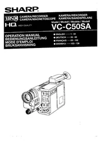


| Product Type | Camcorder |
| Brand | Sharp |
| Model | VC-C50SA |
| Dimensions (W x H x D) | 121 mm x 165 mm x 223 mm (including viewfinder) |
| Weight | 1.4 kg (with viewfinder) |
| Power Supply | DC 9.6 V (battery or AC adaptor) |
| Power Consumption | 8.0 W |
| Recording Format | VHS |
| Recording Time (max) | 30 min (SP) / 60 min (LP) with EC-30 cassette |
| Lens | 6:1 power zoom, F1.6, f=9-54 mm, filter diameter 49 mm |
| Image Sensor | 1/2-inch CCD |
| Minimum Illumination | 15 lux (at F1.6) |
| Viewfinder | 0.6-inch black/white CRT electronic viewfinder |
| White Balance | Full-auto or manual preset (3,200 K / 5,500 K) |
| Focus | Auto or manual (with focus ring) |
| Zoom Control | Power zoom (T/W buttons) and manual zoom lever |
| Recording Modes | SP (standard play) and LP (long play) |
| Fade Function | Automatic fade-in/out (white blank screen) |
| Backlight Compensation | Yes (BLC button, opens iris 1-2 f-stops) |
| Condensation Protection | Warning in counter display, unit stops automatically |
| Safety Features | Do not open cabinet; avoid moisture; no user-serviceable parts |
| Maintenance | Clean cabinet with soft cloth; lens with brush/cleaning paper; avoid benzine/alcohol |
| Repairability | Refer servicing to qualified dealer or service centre |
| Included Accessories | Battery pack BT-51, AC adaptor AA-50S, RF unit VR-S50RF, cassette adaptor VR-50CA, electronic viewfinder EVF-C50P, shoulder strap, system case, etc. |
| Optional Accessories | BT-52 battery pack, car battery cord CC-50P, pause remote control VR-50ME |
Frequently Asked Questions - VC-C50SA SHARP
User questions about VC-C50SA SHARP
0 question about this device. Answer the ones you know or ask your own.
Ask a new question about this device
Download the instructions for your Camcorder in PDF format for free! Find your manual VC-C50SA - SHARP and take your electronic device back in hand. On this page are published all the documents necessary for the use of your device. VC-C50SA by SHARP.
USER MANUAL VC-C50SA SHARP
This apparatus complies with requirements of BS 800 and EEC directive 82/499/EEC.
TO PREVENT SHOCK HAZARD, DO NOT EXPOSE THIS APPLIANCE TO RAIN OR MOISTURE.
This equipment should be used with DC 9.6V= only or recommended AC adaptor.
CAUTION:
To prevent electric shocks and fire hazards, do NOT use any other power source.
CAUTION:
To prevent shock, do not open the cabinet. No user serviceable parts inside. Refer servicing to qualified dealer or service centre.

ATTENTION:
The system select switch on the rear of the provided RF unit VR-S50RF has been set to G (Continental PAL, 5.5 MHz).
Congratulations on a Wise Decision!
With so many brands available, the choice was difficult. But after enjoying the top quality and high performance of this Sharp Camera/Recorder, you'll know you were right.
The purchase of this Camera/Recorder will further enhance your enjoyment of television viewing. Before operating, please read this operation manual to get the most out of your Sharp Camera/Recorder. Also, please save it for future reference, since it will be useful if you have any trouble during operation.
Features
Ultra-compact and ultra-lightweight: a mere 1.4kg. Maximum of 60 minutes recording time in LP mode. 2 1/2" CCD image sensor with F1.6, 6x power zoom with macro focusing. 4 HQ (High Quality) picture. Automatic Focus, White Balance, and Iris Control. 0.6" Electronic Viewfinder/Monitor for instant reviewing. 7 Alarm Indication (Battery, Low exposure, Tape-end, etc)
Important
Audio-visual material may consist of copyrighted works which must not be recorded without the authority of the owner of the copyright. Please refer to relevant laws in your country.
Power Supply
This unit can be operated by connecting it to either the AC adaptor, Battery pack or optional Car battery cord. The AC adaptor incorporates the AUTO VOLTAGE (AC 110–240V, 50/60Hz) function.
Table of Contents
| Features | 2 | Manual Focus | 17 |
| 3 | Backlight Compensation | 18 | |
| Precautions | 4 | REC REVIEW function | 18 |
| Video Cassettes | Assemble Recording | 18 | |
| Major Operating Componentsand their Functions | 5 | Warnings | 19 |
| 8 | Power Save and Tape Protection System | 20 | |
| Power Supply System | 9 | Special Techniques | 21 |
| Charging the Battery Pack | 11 | White Balance and Lighting Information | 23 |
| Using Electronic Viewfinder | 12 | Playback | 25 |
| Attaching the Shoe Adaptor | 12 | Counter Memory Function | 26 |
| Attaching the Shoulder Strap | 12 | Connections for Playback | 27 |
| Adjusting the Grip Strap | 12 | Recording onto Another VCR | 28 |
| Loading and Unloading a Video Cassette | 13 | Using the Cassette Adaptor | 29 |
| Indicators Inside the Electronic Viewfinder | 14 | Using the Pause Remote | |
| Recording Operation | 15 | Control Unit (Optional) | 31 |
| Precautions for Auto-focus | 15 | Using the System Case | 32 |
| One-hour Recording | 16 | Check Before Requesting Service | 33 |
| Auto or Manual? | 16 | Specifications | 34 |
| Rehearsal | 17 |
For safety, strictly observe the following instructions.
- Do not open the cabinet.
- Prevent inflammables, water and metallic objects from entering the unit.
- Do not disassemble or modify the unit.
- Do not use the unit when there is lightning in the vicinity. Disconnect the power cable of connected equipment.
Avoid using the unit under the following conditions:
- Places subject to excessive humidity or dust.
- Near appliances generating strong magnetic or electric fields (speakers, broadcasting antennas, etc.).
- Places subject to soot or steam such as near a cooking stove.
- Places subject to excessive shock or vibration.
- Near a television set (rolling pictures or howling might result). • Extremely hot places.
Do not expose the unit to high temperatures over 40°C for long periods.
If the unit is subjected to direct sunlight, left in a closed car in summer, or placed near a heater, the CCD and the auto-focus sensor may deteriorate and the cabinet may become deformed. Furthermore, this may also cause the transistors and other electronic and mechanical parts to malfunction. Remember the following:
- Do not leave the unit in places over 30°C.
- Do not use the unit in places over 40°C.
- Do not use the unit in places below 0°C.
- Do not use the unit in humid places with over 80% humidity.
- For long storage, select a place between -20°C and 50°C.
Take special care to protect the unit.
- Do not allow the unit to become wet.
- Do not leave the unit in closed cars on hot summer days.
- Take special care not to drop the unit or strike it against hard objects. Protect it from shocks during transportation.
Make it a rule to observe the following instructions.
- Do not remove the battery pack or disconnect other power supply units during recording or playback before pressing the POWER switch to OFF. If not observed, this will cause tape damage.
- When the unit is not in use, remove the battery pack.
Keep the lens and viewfinder eyepiece always clean.
- When the lens is dirty or dusty, blow it off first and then gently wipe with a soft brush or lens cleaning paper.
- The lens is likely to become mouldy if left dirty. Be careful not to damage the CCD and auto-focus sensor. - Do not keep the lens directed at extremely bright objects such as the sun or other light sources for long periods. Although the CCD is less susceptible to such burn than a tube would be, caution should be exercised when using this unit. Most importantly, the lens should be capped except while actually shooting. - If the aperture is left open, even while the camera is not being powered, the CCD may be damaged. - Do not direct the eyepiece of the viewfinder at the sun.
Auto-focus requires a bit of consideration.
- Do not touch the focus ring while the auto-focus mechanism is in operation as this could damage the auto-focus mechanism.
- When a filter or a special-effect lens is to be attached to the end of the lens, be sure to turn power off or switch from the Auto-focus mode to the Manual mode. NEVER attempt to attach a filter or lens while the auto-focus mechanism is operating as this will result in malfunctioning.
Handle the unit carefully.
- Protect the microphone from excessive shocks.
- Do not carry the unit by holding it only by the view-finder.
Moisture condensation disables use of the unit.
- You have observed that pouring cold liquid into a glass will cause drops of water to form on the glass's outer surface. This same phenomenon occurs on the head drum of a video recorder when the recorder is moved to a warm place from a cool place, after heating a cold room, under extremely humid conditions or in a place directly subject to the cool air from an air conditioner.
- Moisture on the head drum can cause severe damage to the video tape, and can lead to internal damage to the recorder itself.
- If moisture condensation occurs on the head drum, a condensation warning appears in the counter display and the unit enters the Stop mode, unable to function. In such a case, wait for a few hours until the indicator disappears.
Maintenance
- When the cabinet is dusty, clean by gently wiping with a soft cloth.
- Avoid the use of strong cleaning agents such as benzine or alcohol as they may damage the cabinet.
- Cleaning should be done only after the battery pack has been removed or other power units have been disconnected.
- The VC-C50SA uses only compact video cassettes carrying the VISC mark.
- Recording onto prerecorded tapes automatically erases the previously recorded video and audio signals.
- An inverted cassette cannot be inserted.
- Do not load and unload the cassette repeatedly without allowing the tape to run at all. This will slacken the tape and thereby damage it.
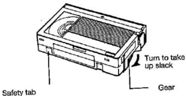
- Make certain before loading the cassette that the tape is not slackened. If there is any slack, turn the gear on the cassette in the direction of the arrow to take up slack.
- The cassette is equipped with a safety tab to prevent accidental erasure. When the tab is removed, recording is impossible. If you wish to record on a cassette whose tab has been removed, use adhesive tape to reseal the slot.
- To avoid excessive exposure to dust and fingerprints, do not open the front tape cover.
Storage of cassettes
• Avoid exposing the cassettes to direct sunlight. Keep them away from heaters. - Avoid storing the cassettes in humid or dusty places. - Do not drop the cassettes. Do not expose them to violent vibrations or shocks. - Do not expose the cassettes to strong magnetic fields (near a motor, transformer or magnet). - Place the cassettes in cassette cases and position them vertically.
Major Operating Components and their Functions
Front view
Left side
Top view
Rear view
Bottom view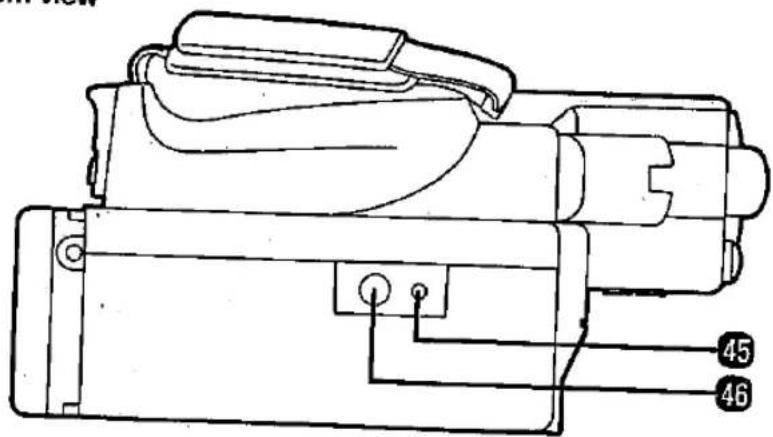
1 6:1 zoom lens f/1.6, f=9-54 mm. Filter diameter: 49 mm.
2 FF/Forward Search button with LED indicator Pressing this button in the Stop mode fast forwards the tape; pressing it in the Play mode allows fast playback (three times normal speed in SP mode, seven times normal speed in LP mode).
MONITOR button Push this button when you wish to rehearse shots before actually recording them. This function allows you to view the scene on the viewfinder without recording it. Push the STOP button to release this function.
4 PLAY button with LED indicator Press to start playback.
5 STOP button with LED indicator Press to engage the Stop mode.
6 PAUSE/ STILL button with LED indicator Press to view a still picture during playback. Press to avoid recording of unwanted material when recording from an external source.
7 REW/Reverse Search button with LED indicator Pressing this button in the Stop mode rewinds the tape; pressing it in the Play mode allows fast playback in reverse (three times normal speed in SP, mode, seven times normal speed in LP mode).
8 REC STBY button with LED indicator Press to engage the Recording Standby mode in which both the REC STBY and PAUSE/STILL LED indicators light. To start recording, press the recording start/stop button 29. While recording, the REC STBY LED indicator is blinking.
9 POWER switch Press to turn power on. The STOP LED indicator will light. Press again to switch off power.
10 SP/LP recording mode select switch Set to SP to record at standard tape speed. Set to LP to record at a slower tape speed, allowing an extended recording time of up to one hour with a single cassette.
11 Earphone jack (PHONE)
12 REMOTE control jack For connection of the optional VR-50ME pause remote control unit.
13 AV OUT connector Both audio and video signals are available from this connector. To dub from this unit, connect the A/V input connectors of a second recorder to this connector, using the provided dubbing cable. For playback with a TV, connect the VR-S50RF RF unit (provided) to this connector and to the TV.
14 Exclusive microphone Omnidirectional condenser microphone for simultaneous sound recording. It can be replaced with other microphones.
15 White balance sensor window Allows light to enter for white balance adjustment.
16 Auto-focus sensor window Allows light to enter for measuring the camera-to-subject distance.
17 FADER button Press this button once to fade out the picture to a white blank screen. For fading in, first press it twice to engage the fade-in standby mode and, after starting recording, press the button where fade-in is to begin.
18 BLC button Iris control is always automatic. For backlight compensation, press this button. While it is being pressed, the iris is 1—2 f-stops wider than that adjusted automatically.
19 FULL AUTO button Pressing this button puts the focus and white balance under automatic control. Auto-focus can be cancelled by pressing the FOCUS button; auto-white balance can be cancelled by pressing the filter button. Pressing the FULL AUTO button in the full-auto mode has no effect.
20 Filter select button Select the filter position depending on the source of light if the auto-white mode is not used. ※ : under a halogen or tungsten lamp. ※ : under daylight. The filter position is changed each time this button is pressed. Check on the viewfinder screen.
21 FOCUS select button
Switch to AUTO for automatic focus, and switch to MANUAL to focus manually. Check on the viewfinder screen. The focus mode is reversed each time this button is pressed. The auto-focus mode can also be selected (together with the auto-white mode) by pushing the FULL AUTO button.
22 EJECT button
To open the cassette holder.
23 Counter display

Tape counter: Shows from "0" to "9999".
Memory mark: Appears when the MEMORY button 25 is pressed.
Battery warning: Flashes when the battery power becomes insufficient for normal operation.
Condensation warning: Appears when excessive condensation occurs inside the unit.
24 RESET button
Press to reset the counter to "0".
25 MEMORY button
Press this button at a point on the tape you want to locate later after resetting the tape counter to "0", and the tape will stop automatically at the counter reading of around "0" during rewind or fast forward.
26 Electronic viewfinder
For monitoring the scene being shot or the playback picture after recording. Several indicators are included.
27 Eyelets for shoulder strap
28 Cassette holder
Insert a VISO video cassette for recording or playback.
29 Recording start/stop button
Press this button in the Recording Standby mode (with the REC STBY button pressed) to start recording. Pressing it again re-engages the Recording Standby mode.
30 Viewfinder cable connector (VF) Connect the viewfinder cable.
31 Finger rest
Place your thumb on this grooved area next to the start/stop switch between Start/Stop operations.
32 DC INPUT terminal
For connection of the provided AA-50S AC power adaptor/battery charger; optional CC-50P car battery cord for DC power supply.
33 Battery pack mounting position
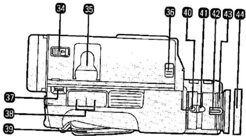
34 Battery pack release button
Slide in the direction of the arrow to detach the battery pack.
35 Viewfinder mount
Attach the provided viewfinder.
36 REC REVIEW button
If you want to review the end of the recorded segment for confirmation, press this button from the Record-Pause mode; the tape will be rewound for about 2 seconds of program time and played back automatically for this section, after which it will stop in the Record-Pause mode in standby for the next shot.
37 TRACKING control
Minimizes noise bars, if observed, during playback.
38 Power zoom buttons
For automatic zooming; "T" for telephoto and "W" for wide-angle.
39 Grip strap
Secures the operator's hand to the hand grip.
40 Macro button
Turn the zoom ring while pressing this button for macro shooting.
41 Manual zoom lever
Use to turn the zoom ring manually.
42 Manual focus lever
Use to turn the focus ring manually.
43 Focus ring
44 Lens cap
Cap the lens when not in use.
45 Stud hole
46 Tripod mounting socket
Power Supply System
The convenient 3-way power supply system gives you a choice of the most appropriate power supply unit, depending on the application.
CAUTION
- No function is available without the power supply or battery.
- Do not use any power supply other than specified.
- Never attempt to use these power supply units with any equipment other than the Camera/Recorder.
Where AC power is not available
Use the battery packs:
• BT-51 (1 Hour battery) • BT-52 (2 Hours battery)
To attach
① Align the marks. ② Slide the battery pack in the direction of the arrow until it locks.

To remove
① Slide the battery pack release button. ② Remove the battery pack by sliding it in the direction of the arrow.

- Remove the battery pack when not in use.
- For charging the battery packs refer to page 9.
With AC power
Use the provided AA-50S AC power adaptor/battery charger.

In a car
Use the optional CC-50P car battery cord.
- Leave the car's engine idling when using the car battery. (For use with 12-V negative-grounded cars only. Check the operation manual of the car or consult a local car dealer.)

Charging the Battery Pack
To charge the battery pack, use the exclusive AC power adaptor/battery charger AA-50S (provided).
A WORD ON THE EXCLUSIVE BT-51/BT-52 BATTERY PACKS
The BT-51/BT-52 are nickel-cadmium batteries. Give attention to the following to make the most of their characteristics.

Temperature ranges:
The recharging time is based on room temperature of 20°C. The lower the temperature, the longer the recharging time.
For charging: 10°C to 35°C
For operating: -10°C to 40°C
For storing: -10°C to 30°C
The battery pack has been kept in the uncharged state for shipment. Therefore, before use, charge it.
• To avoid hazard:
- Do not burn.
- Do not short circuit the terminals.
- Do not modify or disassemble.
- Use only specified chargers.
• To prevent damage and prolong service life:
- Avoid dropping, unnecessary shocks.
- Avoid repeated charging without discharging.
• This unit has a limited service life:
Near the end of its service life, when it begins to deliver less recording time per charge, purchase a replacement.
- It is normal for the unit to be warm after charging or use.
- This is a chemical reaction type battery; its properties are best maintained under the following conditions:
- Optimum charging takes place at temperatures between 10°C and 35°C. Cooler temperatures impede chemical reaction. Warmer temperatures can prevent complete charging.
- Store in a cool dry place. Extended exposure to high temperatures will increase natural discharge and shorten service life.
- Total natural discharge may occur during long storage periods (uncharged storage is preferable; recharge one day before use).
- Remove from charger or powered unit when not in use; some machines use current even when switched off.
Precautions for AA-50S
- If used near a radio, the provided AA-50S AC power adaptor/battery charger may interfere with reception.
- Prevent inflammables, water and metallic objects from entering the unit.
- Do not disassemble or modify the unit.
- Do not apply shocks to the unit.
- Do not subject the unit to direct sunlight.
- Avoid using the unit in extremely hot or humid places.
- Avoid using the unit in places subject to vibrations.
Recording time for the VC-C50SA
- The recording time per charge is influenced by the duration of recording standby, frequency of zooming, etc. It is safer to have spare battery packs.
Charging procedure Charging time
- The charging time differs depending on the ambient temperature and the condition of the battery pack.
- When sliding the battery pack on or off the charger, make sure that the charger's POWER switch is set to OFF.
1
Align the marks.
2
Slide the battery pack in the direction of the arrow until it locks in place.
3 Connect the AC power cord to a wall outlet. 4
Press the POWER switch to ON. The POWER indicator will light first, then the CHARGE indicator will light in a few seconds.
5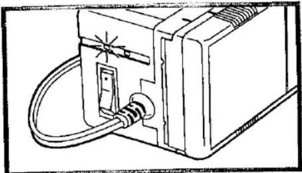
When charging is completed, the CHARGE indicator goes out.
CAUTION
- If the POWER button is left in its ON position after the CHARGE indicator goes out, additional charging continues with a small amount of current.
- Faint oscillation may be heard at the start of charging. This is not due to any defect of the unit.
6
Press the POWER switch to OFF. Remove the battery pack by sliding it off. - The battery pack becomes warm immediately after being charged. This is not due to any defect of the unit.
Using Electronic Viewfinder
Mounting the Viewfinder
Switch off power before mounting or removing viewfinder.
Align the viewfinder's coupling fixture alongside the mounting bracket on the body and slide the fixture into the bracket while pressing down.
Connect the viewfinder cable to the viewfinder cable connector (VF).
Removing the viewfinder
Pull out the viewfinder cable and slide the viewfinder out of the bracket while applying downward pressure.
Diopter adjustment
The viewfinder lens can be adjusted to suit the operator's eyesight by rotating the diopter adjustment ring.
Positioning the viewfinder
The viewfinder can be positioned for best viewability. It can be rotated 360° and tilted up 90°, making almost any viewing angle possible.
Cleaning the viewfinder
The viewfinder eyepiece can be removed for cleaning. Turn the eyepiece counterclockwise and pull it out.
Attaching the Shoe Adaptor
Use this adaptor to re-position the viewfinder for left-eye viewing, or for an external microphone.

To attach the shoe adaptor, remove the viewfinder and slide the adaptor into the bracket usually used for the viewfinder.
3 Use the other shoe for an additional item.
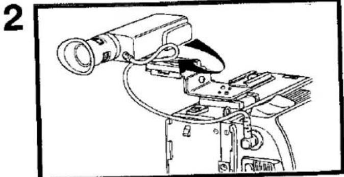
To position the viewfinder for left-eye viewing, slide it into the shoe that is farthest from the camera body.
CAUTION
- Do not attach a video light, otherwise its heat could cause malfunctioning of the VC-C50SA.
Attaching the Shoulder Strap

Attaching the Shoulder Strap
① Slide the strap's fastening plate onto the eyelet tab on the camera body's rear, bottom edge, inserting the tab into the slot in the strap ring. Align the large screw over the tripod mounting socket and screw it in, turning clockwise. ② Swing the viewfinder up to the perpendicular position. Slide the buckle at the other end of the strap onto the eyelet tab on the top edge of the VC-C50SA while drawing back the spring-loaded locking pin.
Adjusting the Grip Strap

Separate the Velcro strip to expand the loop.

Pass your right hand through the loop and grasp the lens grip. Adjust the length of the strap to suit your hand size and refasten the Velcro strip.
Loading and Unloading a Video Cassette
LOADING
1
Press the POWER switch to turn power on
2
Open the cassette holder by pressing the EJECT button.
3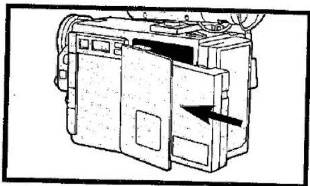
Insert the cassette with its printed arrow facing outward.
First remove tape slack, then insert the cassette correctly. See page 4.
4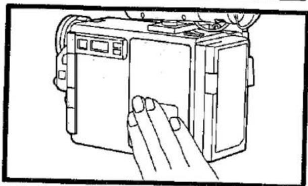
Close the cassette holder by pushing its centre area.
UNLOADING
1
Make sure the unit is in the Stop mode. Press the EJECT button. The cassette holder will open.
2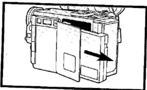
Remove the cassette.
3
Close the cassette holder by pushing its centre area. - When not in use, switch off power.
Notes:
- Do not repeat loading and unloading of the cassette without running the tape, as this will slacken the tape, causing tape damage.
- When the battery is discharged, the tape is unloaded and the power turns off. However, pressing the POWER switch while holding the EJECT button pressed, turns the power on and ejects the cassette.
Indicators Inside the Electronic Viewfinder
The viewfinder of the VC-C50SA provides comprehensive on-screen indications. During recording or rehearsal, you can refer to adjustment aids or warnings.
Recorder status indications
| Recording standby mode |  | Small bar in upper right corner of the screen shows unit in the pause mode or the rehearsal mode (with or without cassette). |
| Recording mode |  | When the start/stop switch is pressed from the pause mode, REC or LP-REC indicates that tape is running properly. |
Camera status indications
| Filter switch setting (Manual mode) |  | Indicates that outdoor filter is in use. | |||
 | Indicates that indoor filter position is in use. | ||||
| Manual focus | 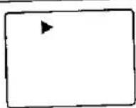 |  | 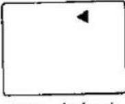 | ► : turn focus ring clockwise until ■ appears.■ : indicates aimed-at subject is in focus.◄ : turn focus ring counterclockwise until ■appears.◆ Auto-focus mode is indicated by none of these appearing on the screen. | |
| Focus behind subject | Correct focus | Focus in front of subject | |||
Warnings
| Tape-end warning |  | When time for remaining tape reaches a few minutes, "REC" begins blinking |
| Battery warning |  | When battery power becomes insufficient for normal operation, "BATTERY" appears and blinks. |
| Low-light warning |  | When amount of light is insufficient, "LIGHT" appears and blinks. |
| Low-contrast warning (Manual-focus) |  | In the Manual-focus mode, if focus-aid indication is difficult because of low contrast, these focus-aid indicators appear simultaneously and blink. |
Recording Operation
1
Press the POWER switch to ON.
2
Insert a video cassette correctly (with its safety tab in place).
Precautions for auto-focus

Focus detection zone: A small area around the centre of the picture, which varies depending on the zoom and focus conditions, is used to detect focus. (No actual indication provided on the screen.)
CAUTION
- Do not touch the focus ring while the auto-focus mechanism is in operation.
- When not in use, do not leave the VC-C50SA in the Auto-focus mode with power on; otherwise light entering the auto-focus sensor window will operate the auto-focus mechanism, consuming power. Correct focus may not be obtained in the following situations. In such cases manual focusing should be performed to obtain proper focus.
 | Two subjects at different distances overlap in the same scene. |
 | Slanted lines only. |
 | Low illumination where the under-exposure indicator appears on the viewfinder screen. |
 | Minute patterns or identical patterns that are regularly repeated. |
Note:
- If the lens and/or auto-focus sensor window are smeared with stains or blurred with condensation, accurate focusing is not possible. Keep them clean. If they become dirty, wipe with a piece of soft cloth. When condensation occurs, dry them by wiping with a soft cloth or wait for conditions in which they become dry.
3

Set the tape speed to SP or LP.
4

Press the REC STBY button. The unit enters the Recording Standby mode (with the REC STBY and PAUSE LED indicators lighting).
Check the viewfinder indications. See page 14.

5

For full-auto operation, press the FULL AUTO button.
For manual override, use the filter and FOCUS buttons.
- Press the filter button so that the required symbol appears on the viewfinder. : when the subject is illuminated by a halogen or tungsten lamp. *: when you shoot in the daytime outdoors.
- For manual focus, press the FOCUS button to MANUAL. A focus-aid indicator will appear on the viewfinder.
One-hour Recording
- To record longer on a single cassette, use the LP (Long Play) mode.
- For LP recording, a higher-capacity battery pack may be used. • SP: 30 minutes LP: 60 minutes
Auto or Manual?
- Iris control is always automatic. Therefore, possible combinations of auto and manual functions are as follows:
| Function\Control | FULL AUTO | FOCUS | FOCUS | |
| White balance | Auto | Manual | Auto | Manual |
| Focus | Auto | Auto | Manual | Manual |
| Iris | Auto | Auto | Auto | Auto |
6
Determine the focus and composition by referring to the viewfinder image. For zooming, see page 22.
Rehearsal
If you wish to rehearse shooting angles, compose scenes, etc., without actually recording on the tape, press the MONITOR button, instead of REC STBY. The aimed-at scene will appear on the viewfinder screen. For full-auto rehearsal, also press the FULL AUTO button. To engage the Recording Standby mode from rehearsal, press the REC STBY button. To only disengage the Rehearsal mode, press the STOP button.
- Rehearsal is possible whether a cassette is loaded or not.
- With a cassette loaded, rehearsal is not possible during rewind or fast forward.
- The power save circuit does not function during rehearsal. (For power save function, see page 20.)
Manual Focus
If the manual focus mode is selected, proceed as follows:
① Zoom in on a subject by pressing the "T" button. ② Focus onto it by turning the focus ring. ③ Determine the composition by pressing the "W" button.

Note:
- When using manual focus mode, be sure to focus the lens at the maximum telephoto position. If you focus on a subject in the wide-angle position, sharply focused images cannot be obtained when zoomed in because the depth of field is reduced at longer focal lengths.
FOCUS INDICATORS
The focus indicators on the viewfinder screen function in manual focus mode.
| Concifion | Indication | Corrective operation |
| Focus point behind the subject |  | Turn the focus ring clockwise until the centre square lights. |
| Correct focus |  | Keep the focus ring in the same position. |
| Focus point in front of the subject |  | Turn the focus ring counterclockwise until the centre square lights. |
| Indication not possible because of low contrast |  | Estimate the subject distance and set the focus ring referring to the distance scale on it. |
7

Press the start/stop button.
- This causes REC or LP-REC to appear on the viewfinder screen, indicating that recording is actually taking place.


8

To stop recording temporarily, press the start/stop button once again.
9
To restart recording, press the start/stop button.
- For a pause longer than 5 minutes, press the POWER switch to OFF.
- If the Recording Standby mode continues for longer than about 5 minutes, the unit switches itself off automatically. To restart recording, turn the power on. This makes clean assembled recordings possible even after a long pause.
Backlight Compensation
- Press the BLC button. While it is being pressed, the iris is 1-2 f-stops wider than that adjusted automatically.

When excessive lighting is located in back of the subject, correct exposure may not be obtainable. To compensate for this, use BLC.

REC REVIEW Function
- If you want to review the end of the last recording for confirmation, press the REC REVIEW button from the Record-Pause mode; the tape will be rewound for about 2 seconds of program time and played back automatically for this section, after which it will stop in the Record-Pause mode in standby for the next shot.

Notes:
• The TRACKING control should be at its centre position. - Distortion might occur when playback starts. This is normal.
Assemble Recordings
- Repeating steps 8 and 9 produces assemble recordings. In playback, the picture may be slightly distorted at the point between separate takes. This is not due to any defect of the unit.
- If recording is restarted from the Stop mode, a few frames of the previously recorded picture will be replaced with a new recording. To avoid this, follow the technique described in "To record onto a partially recorded tape" on page 20.
10

To end recording, press the STOP button.
- After making sure that the tape has stopped, press the POWER switch to OFF.
Viewfinder Monitoring
- Rewind the tape to a point from which you want to check the recording.
- Press the PLAY button, and you can view the playback picture on the viewfinder screen.
Notes:
- Pressing the PAUSE/STILL button during playback stops the picture on the viewfinder screen.
- Forward/Reverse search is also possible in both directions.
Tape-end warning![graph TD A["RECE"] -->|Blinking| B["LP-REC"]](/content/2026/05/1047967/images/e0b683ee85c813e2d9da355bf7f6ef95f5aaa3d92a74082bdc387cecef2ef97e.jpg)
- "REC" or "LP-REC" on the viewfinder screen blinks faster a few minutes before the end of the tape.
- When the end of the tape is reached during recording, the Stop mode engages automatically.
Battery warning
- When the battery power is coming to an end, a battery warning indication appears both in the viewfinder and the counter display. Replace the battery pack with a fully charged one.
- After these indications appear, the power turns off automatically. In this state, however, pressing the POWER switch while holding EJECT button pressed, turns the power on and ejects the cassette.
Low-light warning
- If the blinking "LIGHT" indicator appears on the viewfinder screen, the amount of light is insufficient. Increase the lighting.
To replace the battery pack during recording
1 If the battery warning appears in the viewfinder or the counter display while recording, stop recording by pressing the POWER switch to OFF, not the STOP button.
2 Replace the battery pack with a charged one.
Press the POWER switch to ON. - The unit will be in the Recording Standby mode. 4 Press the recording start/stop button to start recording.
To record onto a partially recorded tape
1 Play back the tape to a point where you wish a new recording to start.
- Use the Forward/Reverse Search button for faster location.
2 Press the PAUSE/STILL button at the located point.
• The unit will enter the Still mode.
Press the REC STBY button. - The unit will enter the Recording Standby mode. 4 Press the recording start/stop button to start recording.
Power Save and Tape Protection System
- To save battery power, the VC-C50SA (when battery-operated, regardless of whether recording camera signals or an external source) switches itself off automatically in the following situations: (1) When left for longer than 5 minutes in the Stop mode. (2) When left for longer than 5 minutes in the Recording Standby (Record-Pause) mode.
- To protect the tape, the VC-C50SA (regardless of whether battery-operated or AC-powered) releases tape tension slightly and switches itself off automatically if left for longer than 5 minutes in the Recording Standby (Record-Pause) mode.
- For the same reason, the VC-C50SA enters the Stop mode and switches itself off automatically if left for longer than 5 minutes in the Still mode.
Battery operation![graph LR A["STOP"] --> B["POWER OFF"] style A fill:#fff,stroke:#000 style B fill:#fff,stroke:#000](/content/2026/05/1047967/images/0a78d1a7588c76ce134c02b05bd1ec84c9af919b4984817ab89be2d056ad9a7b.jpg)
Battery/AC operation![graph LR A["REC PAUSE"] --> B["POWER OFF"] style A fill:#f9f,stroke:#333 style B fill:#ccf,stroke:#333](/content/2026/05/1047967/images/d0c4e04ee4fe11a3d409a5d3d5ca9dc310b849cf57c57e417ec261ef4f413839.jpg)
![graph LR A["STILL"] --> B["STOP"] --> C["POWER OFF"]](/content/2026/05/1047967/images/015d637ef1c73ea3f1b5421eec0627164d4d7cbc39f23a8f9673622a255e7ee4.jpg)
Special Techniques
Fade-in/out
The VC-C50SA is equipped with an automatic fade mechanism for allowing smooth fade-in and fade-out with a white-coloured blank screen. Audio also fades in sync with video.
Automatic fade-in
Determine the composition in the Recording Standby mode and press the FADER button twice to engage the fade-in standby mode. The screen will become white quickly.

Press the start/stop button and press the FADER button. Fade-in will start and be completed in about 3 seconds.
NOTE
- If you want to delay the start of fade-in, press the start/stop button and, after a desired time has elapsed, press the FADER button.

1 Automatic fade-out Start shooting as usual.
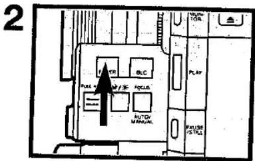
Press the FADER button where you want fade-out to start. The fade-out will be completed in about 3 seconds.

Stop shooting by pressing the start/stop button after fade-out has been completed.
Zooming
When the focal length of the lens is varied by turning the zoom ring, the image appears to come nearer to or retreat from the viewer.

Power zooming
Press "T" for zooming in and "W" for zooming out.
Zoom in


Zoom out

Manual zooming
Rotate the zoom lever downwards for zooming in and upwards for zooming out.
Macro Shots
Normally, focusing is possible only for subjects that are more than 1m away from the camera. By setting the lens to the Macro mode, it is possible to manually focus in on any subject located inside that limit, right up to the front of the lens. The MACRO and ZOOM ranges combined give continuous shooting ability from close-up to infinity.

Engage MACRO
While pressing in the macro button, turn the zoom ring in the direction of the arrow until the number "9" on the zoom ring passes the index line.
Focus
Focus by turning the zoom ring slowly.
- Use the zoom ring to focus in the MACRO range.
- Turning the focus ring will slightly alter the angle of view of the lens.
- The zoom and auto-focus mechanisms do not function during macro shooting.
Release MACRO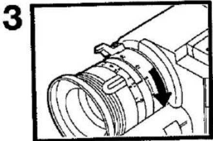
To release the Macro mode, turn the zoom ring in the direction of the arrow until the number "9" passes the index line.
White Balance and Lighting Information
What is "colour temperature"?
Light is composed of various colour components in different proportions. A relationship exists between the temperature of a light source and the colour components of the emitted light; as the temperature rises, the colour of the light varies from red, orange, yellow, white to blue in that order. "Colour temperature" is a value that expresses differences in colour among light sources, measured in Kelvin degrees. Bluish light has a higher colour temperature than reddish light.
What is "white balance"?
Making the colours look natural on TV is what white balance is all about. Because a camera is not as adaptable as the human eye, if a light source is reddish, white subjects in that light are recorded as reddish. White balance adjustment is performed to compensate for colour temperature variations of light so that whites are reproduced as white. Correct white balance makes all other colours correct. VC-C50SA can perform automatic white balance adjustment in the full-auto mode. However, if illumination is insufficient, white balance adjustment cannot be performed. To obtain correct colours, therefore, sufficient illumination is essential.
How to get good colour pictures
The simplest way is to provide sufficient lighting (close to the camera's reference illuminance) and accurately adjust the camera to the colour temperature of that lighting. If light sources of different colour temperatures are used together, accurate white balance adjustment is very difficult. For example, if natural light is mixed with artificial light, which is likely to occur next to windows, correct colours of the subject are difficult to obtain. It is recommended in such cases that curtains in the room be closed to shut out light from outside. Also, when artificial lighting devices are used, they should all have the same colour temperature. For example, it is recommended that incandescent or halogen lamps not be used together with fluorescent lighting.
Colour temperatures of different light sources
What is "Illuminance"?
What is "Illuminance"? "Illuminance" (also called 'luminance') is the intensity or brightness of light, expressed in lux. The VC-C50SA is designed to provide best pictures under the conditions of a 700-lux illuminance, although shooting is possible all the way down to 15 lux.
Illumination Guide Brightness approximations
| 10 lux | Candle at 20 cm. 10–15 luxCigarette lighter at 30 cm. 15 luxDuring intermission at movie theatre. 15–35 lux |
| 100 lux | Staircase in department store. 100–200 luxWorkshop in machinery factory. 150–200 luxArcade at night. 150–200 luxIndoor golf practice range. 200–300 luxFlashlight at 1 metre. 250 luxStudy desk with fluorescent lighting. 400 luxOffice with fluorescent lighting. 400–500 luxLibrary reading room. 400–500 luxBowling alley. 500 luxSales floor of department store. 500–700 luxTicket window of station. 650 luxClear day one hour before sunset. 1,000 luxCloudy day one hour after sunrise. 2,000 lux |
| 1,000 lux | |
| 10,000 lux | Cloudy day at 10 AM. 25,000 luxCloudy day at noon. 32,000 luxClear day at 3 PM. 35,000 luxClear day at 10 AM. 65,000 luxClear day at noon. 100,000 lux |
| 100,000 lux |
*The above table gives approximations only. Use the figures as guidelines.
The VC-C50SA permits playback of recorded VHSO video cassettes. For connections refer to pages 27 and 28. PAL SECAM
Preparation
- Set the aerial select switch of the VR-S50RF RF unit to VCR and the TV receiver's channel selector to your video channel (specified AV channel).
1

Connect a power supply unit. (Battery or AC operation: see page 8.)
2

Press the POWER switch to ON.
3
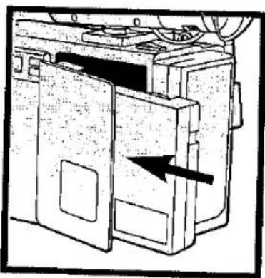
Insert a pre-recorded cassette.
First remove tape slack, then insert the cassette correctly. See page 4.
4

Press the PLAY button. Playback will start.
- The SP/LP switch may be in either position. The SP or LP mode recording is automatically detected and played back at the correct speed respectively.
- When the end of the tape is reached during playback, the Rewind mode engages automatically.
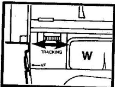
Tracking adjustment
If noise bars appear on the screen, adjust the TRACKING control. Turn it slowly in either direction to minimize noise bars. After playing a particular tape, return the TRACKING control to the centre position.

Forward/Reverse Search
Still playback
Fast-speed playback in the forward direction
Press the FF button in the Play mode. Playback will be speeded up to 3 times normal speed in SP mode, 7 times normal speed in LP mode, as long as the button is being pressed.
Fast-speed reverse playback
Press the REW button in the Play mode. The tape will be played back in the reverse direction at 3 times normal speed in SP mode, 7 times normal speed in LP mode, as long as the button is being pressed.

Press the PAUSE/STILL button during playback. The picture will stop on the screen. - After about 5 minutes of still playback, the unit enters the Stop mode automatically for tape protection and switches itself off.
Note
- Noise may appear or pictures may become monochrome from time to time during Forward/Reverse search and still playback. This is not due to any defect of the unit.
Counter Memory Function
The VC-C50SA incorporates a counter memory mechanism which facilitates locating a specific tape segment.
1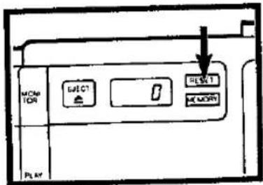
Press the RESET button to reset the counter to "0".
3
After recording or playback, press the STOP button, then the REW button. The tape will automatically stop at the counter reading of around "0".
Notes:
- The counter memory function is effective in the Fast Forward mode as well.
- To cancel the memory function, press the MEMORY button.
- When the power supply unit is disconnected, all indications on the counter display disappear and the counter memory function is cancelled after about 30 seconds.
2
Press the MEMORY button. The "M" mark will appear.
4
Press the PLAY button to start playback.
Connections for Playback
The VC-C50SA includes playback circuits and allows playback of pre-recorded cassettes simply by connecting to a television set.

1. Remove the aerial cable from the TV receiver.
2. Connect the aerial cable to the ANTENNA IN terminal of the RF unit.

3. Connect the RF OUT terminal of the RF unit to the aerial terminal of the TV receiver using the provided aerial cable.

PRECAUTIONS FOR VR-S50RF
- For exclusive use with the VC-C50SA Camera/Recorder.
- Do not disassemble or remodel the VR-S50RF.
- Do not expose it to strong shocks.
- Unplug the connected equipment during lightning storms. (Never touch the aerial cable.)
4. Connect the VIDEO/AUDIO INPUT cable of the RF unit to the AV OUT connector of the VC-C50SA.

5. Adjust the RF converter output channel according to your VIDEO CHANNEL.

① RF converter channel adjustment screw
The RF unit permits playback of video and audio recordings through a TV receiver. The signals from the RF unit are viewed through a vacant channel not used for broadcasting in your area. The output frequency of the RF converter has been set to correspond to a broadcast on UHF channel 36. To view playback pictures from the VC-C50SA with your TV receiver, tune its specified AV channel to UHF channel 36. If channel 36 is employed for broadcasting in your area, readjust the RF con-
verter output channel to one of the vacant channels between 32 and 40.
- Set the TV receiver to one of the vacant channels.
- Power the VC-C50SA.
- Put the VC-C50SA in the Rehearsal mode (see page 17).
- Set the TV/VCR switch of the RF unit to VCR.
- While monitoring the output signal on the TV screen, turn the RF converter channel adjustment screw ① so that the monitored picture comes in most clearly.
- When you wish to view video cassette programmes, always select the AV channel on the TV receiver which has been tuned to the output frequency of the RF converter.
② TV system select switch (I/G)
When you use a TV receiver built to the British PAL standard, shift the system select switch ② to "I".
CAUTION:
To view the VC-C50SA recordings with a TV receiver, use a TV receiver having a specified AV channel and employ this AV channel as your VIDEO CHANNEL, otherwise playback may be disturbed with vibrating or bending pictures. AV channels refer to channels exclusively for video playback; because of AFC circuits applied to these channels, the playback pictures can be stabilised. Recent TV receivers have one or more AV channels.
OPERATION
Viewing video cassettes being played back with the VC-C50SA
To view video cassettes or to monitor the recording, set the TV/VCR switch of the RF unit to VCR and the TV channel selector to the channel corresponding to the RF output channel.
Viewing television programmes
Set the TV/VCR switch to TV, and the TV receiver will function as usual.
Recording onto Another VCR

Connection
- Connect the AV OUT connector of the VC-C50SA to the AUDIO IN and VIDEO IN connectors of the video recorder using either of the provided A/V output cables, depending on the deck you are using.
- Connect a television to the video recorder to monitor the picture while dubbing.

Operation
- Put the VC-C50SA in the Play mode and the connected recorder in the Record mode to copy the recording. To edit out unwanted material, press the recorder's PAUSE button.
Using the Cassette Adaptor
The VHS compact video cassettes recorded with the VC-C50SA can be played back with a standard VHS machine by using the provided VR-50CA Cassette Adaptor.
(A compact video cassette installed in the cassette adaptor is fully compatible with a standard VHS machine for both recording and playback.)
Inserting a compact video cassette

Note:
If there is slack in the video tape when inserting the compact cassette into the adaptor, the tape may become damaged. To take up slack in the tape, turn the gear in the direction of the arrow.
① Push the sliding latch in the direction of the arrow to open the door. ② Insert the cassette as illustrated. ③ Close the compartment door. • The tape will be loaded automatically. ④ The loading dial turns and stops with its indented dot aligned with the blue dot. The safety catch will retract. This indicates that the tape loading is completed.

CAUTION
Check the tape condition after inserting the cassette and tape loading is completed:
1) Check to see if there is any tape slack. (Do not open the tape cover.) 2) If there is tape slack, remove it by turning the reel in the direction of the arrow.

CAUTION:
During tape loading and unloading, do not touch this reel for safety and tape protection.
Note:
During special-effects playback (slow motion, still frame, etc.) the picture may vibrate or noise bars may appear on the screen.
Removing the compact video cassette
- Push the sliding latch in the direction of the arrow.
- The tape will be unloaded automatically.
- The compartment door will open automatically when the indented dot on the loading dial stops aligned with the red dot. The safety catch protrudes to show that the tape has been unloaded.
- Using the smaller hole on the underside of the adaptor, push the cassette up from below and remove it.
Caution:
Remove the cassette after tape unloading is completed.
- Close the compartment door.
NOTE
When loading or unloading the compact cassette, slight mechanical noise can be heard. This is not due to any defect of the unit.
If the battery is fully discharged during tape loading or unloading, the loading mechanism stops midway. In such a case, proceed as follows to load or unload the tape manually.

- Slide the battery compartment cover in the direction of the arrow and remove the battery.

- Using a coin, turn the loading dial until it stops, clockwise for loading or counterclockwise for unloading.
Normally, do not perform manual loading or unloading.
Battery replacement
- Install an "AA" size battery in the battery compartment observing polarity.
PRECAUTIONS
- The protruding safety catch indicates that loading of the tape has not yet been completed. In this condition, NEVER attempt to load the cassette adaptor into a recorder, as this could damage both.
- This cassette adaptor is precision-manufactured. Avoid violent vibrations or shocks. Do not drop, disassemble, or modify it, otherwise malfunctions may result.
- Do not repeatedly load and unload the cassette adaptor into a recorder without allowing the tape to run. This will slacken the tape and thereby damage it. • The cassette adaptor cannot be loaded upside down.
- Do not touch the tape when inserting a compact cassette into this cassette adaptor. After use, remove the cassette from the adaptor.
- When placing the cassette adaptor into its case, push in the safety catch so that the cassette adaptor slides into the case.
Using the Pause Remote Control Unit (Optional)
The remote control unit VR-50ME (optional) permits recording start/stop to be controlled from a distance.

Plug the remote control cable into the REMOTE connector:
2 Press the REC STBY button to engage the Recording Standby mode.
3 To start recording, set the remote control's switch to REC; to stop temporarily, set it to PAUSE.
Using External Microphone
The provided microphone can be detached. To use another microphone, do the following:

Remove the provided microphone by grasping the microphone's base and then pulling it straight out.

Plug the external microphone's cord into the microphone jack.
Using Tripod Mounting

Align the screw and camera direction stud of the tripod with the camera's tripod mounting socket and stud hole, and firmly tighten the screw.
Using the System Case
This SYSTEM CASE accommodates not only the VC-C50SA Camera/Recorder, but also its exclusive accessories, including spare battery packs, cassettes, an AC Power Adaptor/Battery charger, and the RF unit. When not using the VC-C50SA and its accessories, keep them in the SYSTEM CASE.
How to attach/detach the shoulder strap (provided)
- To attach:
For each buckle, position it against a receiving lock on the side of the case and press on it until a click is heard.

- To detach: Lift up on the buckle lever of each buckle.

How to open/close the case
• To open:
slide the latch on either side of the handle in the direction of the arrow, as shown.

• To close: Press down on the lid until a click is heard.

How to lock the case
Close the case, insert the key, and turn the key clockwise.
- Outer lock

- Inner lock

* When traveling with the case, be sure to lock both the inner and outer locks.
Suggested placement of the Camera/Recorder and accessories
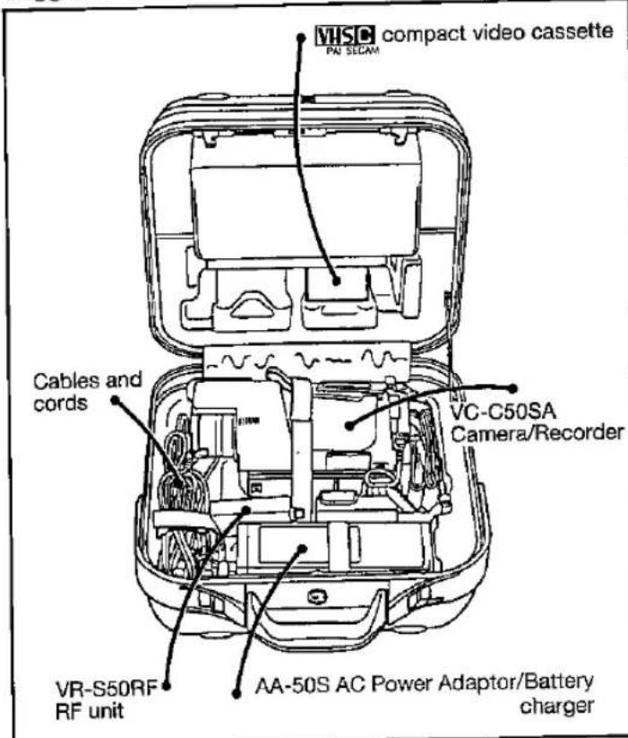
Kangaroo pocket
• To open:
Slide the latch in the direction of the arrow, as shown.

- Outer section: Holds two BT-52 (or BT-51) battery packs, or the AV cable and small accessories. Holds the VR-50CA cassette adaptor or three compact video cassettes.
- Inner section:

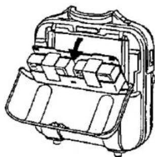
■ Dimensions: 344(W)×403(H)×191(D) mm ■ Weight: 1.96 kg (with strap)
Caution: To clean the outside of the case, wipe it with a cloth moistened with diluted furniture cleaner, then wipe dry with a dry cloth. Do not use paint thinner or cleaning agents containing benzene.
Check Before Requesting Service
What may initially appear to be trouble is not always a real problem. Make sure first....
| Symptoms | Check points |
| Power | |
| No power is supplied. | •Is the battery pack correctly installed?•Is the battery pack charged?•Is the power supply unit correctly connected?•Is the POWER switch of the connected AC adaptor set to ON? |
| Recording | |
| Recording is impossible. | •Check to see if the cassette safety tab is in place. See page 4. |
| Picture colours greatly differ from actual subject colours. | •If in the manual white balance mode, check the setting of the /* button. |
| No sound is recorded with an external microphone. | •Is the microphone's switch set to ON? |
| Recording does not start. | •Have you pressed the REC STBY button first? |
| Playback | |
| Tape is running, but no playback picture appears. | •Is the TV/VCR switch of the RF unit set to VCR?•Is the TV receiver set to your video channel? |
| Noise bars appear in the playback picture. | •Use the TRACKING control to reduce noise bars. |
| Playback picture is blurred or interrupted while TV programs received are clear. | •Video heads may be dirty or worn out. For head cleaning or replacement, consult a qualified dealer or service centre. |
| Tape transport | |
| Tape stops during fast forward or rewind. | •Is the "M" indication visible in the tape counter?If so, press the MEMORY button to cancel the memory function. |
| Rewinding or fast forwarding is impossible. | •Check to see if the tape has already been fully wound on one reel or the other. |
| Other | |
| No function is available with more than two mode indicators lit. | •If this should happen when using a power supply unit other than the battery pack, turn the POWER switch on and off.Replace the batteries. |
The VC-C50SA is a microcomputer-controlled device. External noise and interference might prevent it from functioning properly. In such cases, first disconnect its power supply unit (battery pack, AC power adaptor, etc.); and then reconnect it and proceed as usual from the beginning.
| Format | : VHS standard | |
| Power source | : DC 9.6 V--- | |
| Power consumption | : 8.0 watts | |
| Signal system | : PAL | |
| Recording system | : Luminance: FM recordingColor: Converted sub-carrier direct recordingConforms to VHS standard | |
| Cassette | : VHS-C cassette | |
| Tape speed | (SP) | : 23.39 mm/sec |
| (LP) | : 11.70 mm/sec | |
| Recording time Max. | (SP) | : 30 minutes (with EC-30 cassette) |
| (LP) | : 60 minutes (with EC-30 cassette) | |
| VIDEO | ||
| Output | : 1Vp-p, 75 ohms, unbalanced (via AV OUT connector) | |
| S/N ratio | : 40 dB (with Rohde & Schwarz noise meter) | |
| AUDIO | ||
| Output | : -6 dBs, 1 k-ohm (via AV OUT connector) | |
| Microphone input | : -68 dBs, high impedance, unbalanced | |
| Pickup | : 1/2"-format CCD | |
| Minimum required illumination | : 15 lux (at F 1.6) | |
| Illumination range Lens | : 15–100,000 luxF 1.6,f=9–54 mm.6:1 power zoom lens with auto iris control and macro position, filter diameter 49 mm | |
| Viewfinder | : Electronic viewfinder with 0.6" black/white CRT | |
| Color temperature switching | : Switchable(3,200 K/5,500 K) | |
| White balance adjustment | : Full-auto/preset standard | |
| Operating temperature | : 0°C to +40°C | |
| Operating humidity | : Less than 80% | |
| Storage temperature | : -20°C to +50°C | |
| Weight | : 1.4 kg (with viewfinder) | |
| Dimensions | : 121(W)×165(H)×223(D) mm(incl. viewfinder) | |
AA-50S SPECIFICATIONS
| Power supply | : AC 110-240 V~, 50/60 Hz |
| Power consumption | : 30 watts |
| Rated output voltage | : DC 9.6V— |
| Rated output current | : 1.2 A |
| Charging system | : Constant current, peak detection, timer controlled |
| Dimensions | : 57(W)×67(H)×200(D) mm |
| Weight | : Approx. 770 g |
VR-50CA SPECIFICATIONS
| Type | : VHS cassette adaptor |
| Dimensions | : 188(W)×25(H)×104(D) mm |
| Weight | : 235 g |
| Accessory | :"R6"-size battery×1 |
VR-S50RF SPECIFICATIONS
| Output channel | : UHF channels 32-40(adjustable) |
| Initial channel setting | : UHF 36 |
| Power source | : DC 8V—20mA(from Video Movie) |
| Dimensions | : 55(W)×93(H)×24(D) mmexcl. cable |
| Cable length | : 2.5 m |
| Weight | : Approx. 160 g |
Provided accessories
| High-capacity battery pack (1.0 AH) BT-51 |
| AC power adaptor/battery charger AA-50S |
| RF unit VR-S50RF |
| Aerial cable |
| A/V output cable |
| Compact video cassette EC-30 HG |
| Cassette adaptor VR-50CA |
| Electronic viewfinder EVF-C50P |
| Shoe adaptor |
| Lens hood |
| Lens cap |
| Shoulder strap VR-50SL |
| System case VR-51SB |
| Grip pad |
Optional accessories
| 2-Hour battery pack BT-52 |
| Car battery cord CC-50P |
| Pause remote control unit VR-50ME |
| AV output cable (BNC/RCA); VR-52AV |
Design and specifications subject to change without notice.
ATTENTION:
Top of device
Rear view

Bottom of device
6x zoom lens
F 1.6, f=9-54 mm. Filter diameter: 49 mm.
Removing
Note:
Notes:
Motorized zoom
Manual zoom
Tracking adjustment
Picture search
Note:
• Remove:
• Close:
• Inner lock


■Dimensions: 344(W)×403(H)×191(D) mm
- TO PREVENT SHOCK HAZARD, DO NOT EXPOSE THIS APPLIANCE TO RAIN OR MOISTURE
- CAUTION
- ATTENTION
- CONGRATULATIONS ON A WISE DECISION
- FEATURES
- IMPORTANT
- POWER SUPPLY
- MAINTENANCE
- STORAGE OF CASSETTES
- MAJOR OPERATING COMPONENTS AND THEIR FUNCTIONS
- FOCUS SELECT BUTTON
- EJECT BUTTON
- COUNTER DISPLAY
- RESET BUTTON
- MEMORY BUTTON
- ELECTRONIC VIEWFINDER
- EYELETS FOR SHOULDER STRAP
- CASSETTE HOLDER
- RECORDING START/STOP BUTTON
- VIEWFINDER CABLE CONNECTOR (VF) CONNECT THE VIEWFINDER CABLE
- FINGER REST
- DC INPUT TERMINAL
- BATTERY PACK MOUNTING POSITION
- BATTERY PACK RELEASE BUTTON
- VIEWFINDER MOUNT
- REC REVIEW BUTTON
- TRACKING CONTROL
- POWER ZOOM BUTTONS
- GRIP STRAP
- MACRO BUTTON
- MANUAL ZOOM LEVER
- MANUAL FOCUS LEVER
- FOCUS RING
- LENS CAP
- STUD HOLE
- TRIPOD MOUNTING SOCKET
- POWER SUPPLY SYSTEM
- WHERE AC POWER IS NOT AVAILABLE
- USE THE BATTERY PACKS
- TO ATTACH
- TO REMOVE
- WITH AC POWER
- IN A CAR
- CHARGING THE BATTERY PACK
- A WORD ON THE EXCLUSIVE BT-51/BT-52 BATTERY PACKS
- TEMPERATURE RANGES
- THE BATTERY PACK HAS BEEN KEPT IN THE UNCHARGED STATE FOR SHIPMENT. THEREFORE, BEFORE USE, CHARGE IT
- PRECAUTIONS FOR AA-50S
- USING ELECTRONIC VIEWFINDER
- MOUNTING THE VIEWFINDER
- ATTACHING THE SHOE ADAPTOR
- ATTACHING THE SHOULDER STRAP
- ADJUSTING THE GRIP STRAP
- LOADING AND UNLOADING A VIDEO CASSETTE
- LOADING
- UNLOADING
- NOTES
- INDICATORS INSIDE THE ELECTRONIC VIEWFINDER
- RECORDING OPERATION
- PRECAUTIONS FOR AUTO-FOCUS
- NOTE
- ONE-HOUR RECORDING
- AUTO OR MANUAL
- MANUAL FOCUS
- FOCUS INDICATORS
- BACKLIGHT COMPENSATION
- REC REVIEW FUNCTION
- ASSEMBLE RECORDINGS
- TO REPLACE THE BATTERY PACK DURING RECORDING
- TO RECORD ONTO A PARTIALLY RECORDED TAPE
- POWER SAVE AND TAPE PROTECTION SYSTEM
- SPECIAL TECHNIQUES
- FADE-IN/OUT
- ZOOMING
- MACRO SHOTS
- WHITE BALANCE AND LIGHTING INFORMATION
- WHAT IS "COLOUR TEMPERATURE
- WHAT IS "WHITE BALANCE
- HOW TO GET GOOD COLOUR PICTURES
- WHAT IS "ILLUMINANCE
- PREPARATION
- TRACKING ADJUSTMENT
- FORWARD/REVERSE SEARCH
- STILL PLAYBACK
- COUNTER MEMORY FUNCTION
- CONNECTIONS FOR PLAYBACK
- PRECAUTIONS FOR VR-S50RF
- ① RF CONVERTER CHANNEL ADJUSTMENT SCREW
- OPERATION
- VIEWING VIDEO CASSETTES BEING PLAYED BACK WITH THE VC-C50SA
- VIEWING TELEVISION PROGRAMMES
- RECORDING ONTO ANOTHER VCR
- CONNECTION
- USING THE CASSETTE ADAPTOR
- INSERTING A COMPACT VIDEO CASSETTE
- REMOVING THE COMPACT VIDEO CASSETTE
- BATTERY REPLACEMENT
- PRECAUTIONS
- USING THE PAUSE REMOTE CONTROL UNIT (OPTIONAL)
- USING EXTERNAL MICROPHONE
- USING TRIPOD MOUNTING
- USING THE SYSTEM CASE
- HOW TO ATTACH/DETACH THE SHOULDER STRAP (PROVIDED)
- HOW TO OPEN/CLOSE THE CASE
- HOW TO LOCK THE CASE
- SUGGESTED PLACEMENT OF THE CAMERA/RECORDER AND ACCESSORIES
- KANGAROO POCKET
- CHECK BEFORE REQUESTING SERVICE
- REMOVING
- PICTURE SEARCH
- REMOVE
- CLOSE
- INNER LOCK
Brand : SHARP
Model : VC-C50SA
Category : Camcorder