ICA-HM620 - Security Camera Planet - Free user manual and instructions
Find the device manual for free ICA-HM620 Planet in PDF.


| Product Type | Security Camera |
| Model | ICA-HM620 |
| Brand | Planet |
| Image Sensor | 1/2.8" Progressive Scan CMOS |
| Effective Pixels | 1920 x 1080 (2 Megapixels) |
| Lens Type | Fixed, 4mm |
| Night Vision | Infrared LEDs, up to 30m |
| Day/Night Mode | Auto IR cut filter |
| Video Compression | H.264, MJPEG |
| Frame Rate | 30fps at 1080p |
| Network Interface | 10/100 Ethernet (RJ-45) |
| Supported Protocols | TCP/IP, HTTP, DHCP, DNS, ONVIF |
| Power Supply | DC 12V or PoE (IEEE 802.3af) |
| Power Consumption | Max 5W |
| Ingress Protection | IP66 (weatherproof) |
| Mounting Type | Wall or ceiling bracket |
| Dimensions (W x D x H) | 70 x 70 x 150 mm |
| Weight | Approx. 500g |
| Operating Temperature | -30°C to 60°C |
| Storage Temperature | -40°C to 70°C |
| Memory Card Slot | Micro SD (max 128GB) |
| Reset Button | Yes, hold 10 seconds |
Frequently Asked Questions - ICA-HM620 Planet
User questions about ICA-HM620 Planet
0 question about this device. Answer the ones you know or ask your own.
Ask a new question about this device
Download the instructions for your Security Camera in PDF format for free! Find your manual ICA-HM620 - Planet and take your electronic device back in hand. On this page are published all the documents necessary for the use of your device. ICA-HM620 by Planet.
USER MANUAL ICA-HM620 Planet
2 Mega-Pixel PoE Plus Speed Dome Internet Camera
ICA-HM620
Quick Installation Guide
Table of Contents
Verify The Contents Inside Package Box 3
Physical Installation 4
Further Configuration 12
Verify The Contents Inside Package Box
The package should contain the below items. If any item is missing or damaged, please contact the seller immediately.
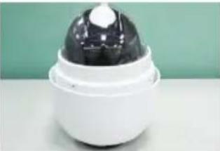 | 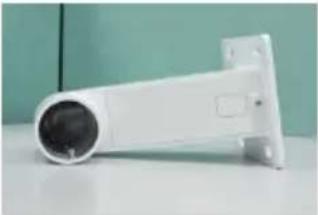 | 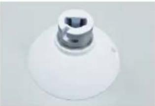 |
| Dome Camera with Dome Cover | Compact Pendent Mount Outdoor Mount Kit | |
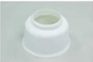
natural_image
White plastic cap with a narrow neck and a hollow center (no text or symbols visible)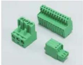
natural_image
Three green plastic electrical connectors with terminal blocks, shown from different angles (no text or symbols visible)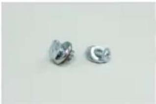
natural_image
Two metallic oval-shaped objects with reflective surfaces, no text or symbols visible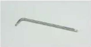 | 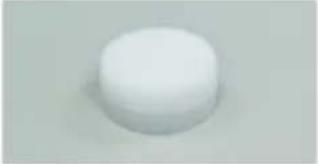 | 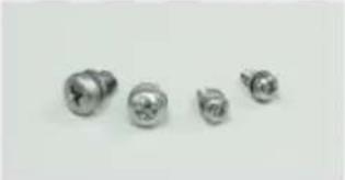 |
| Security Tool Lubricant M3/M5 Standard Screw | M3/M5 Security Screw | |
 |  | 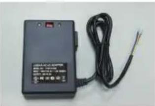 |
| AC Power Adapter | ||
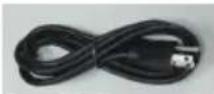 | ||
| Quick Installation Guide CD-ROM Power Cord | ||
Physical Installation
-
During the installation, please take care and avoid crash. That may cause the device damage or cause injury of the installer.
-
Please make sure the hardware had been located on the wall properly. If the hardware drops down, it is possible make someone injury or hurt. Please check the hardware again after the installation.
-
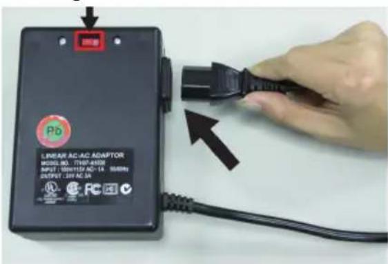
Please according to the practical local power voltage to adjust the power switch. The wrong input voltage may cause the device damage.
Step 1
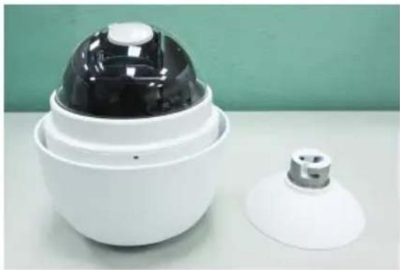
Unpack the Dome Camera's package and take out the Dome Camera unit.
natural_image
White spherical security camera with black dome and lid, next to a smaller white dome-shaped object on a light surface (no text or symbols visible)Step 2
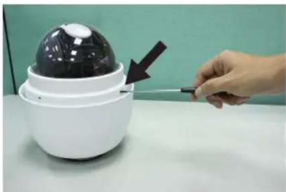
Tighten the knob to remove the cover dome and the lens protector.
natural_image
Hand holding a screwdriver next to a white spherical security camera with a black dome (no text or symbols visible)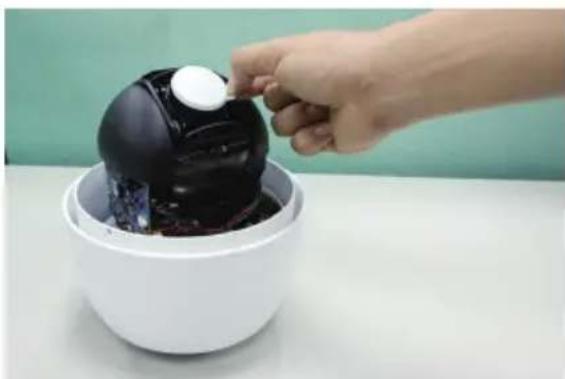
natural_image
Hand placing a white object into a black, glossy dessert bowl on a white surface (no text or symbols visible)Step 3
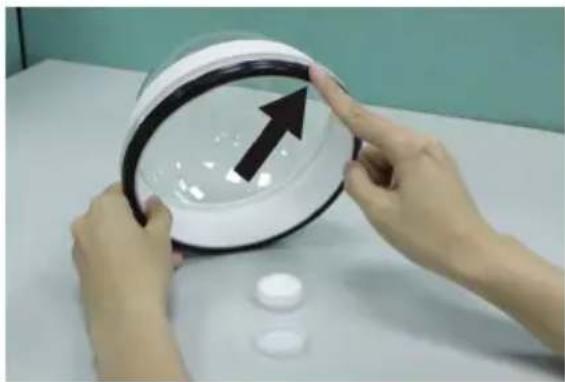
Attach the dome cover to the camera body. Before doing that, apply some lubricant on the cover's water-proof rubber to make the installation process smoother.
natural_image
Hands holding a magnifying glass over a transparent dome, with an upward arrow and two small white objects nearby (no text or symbols visible)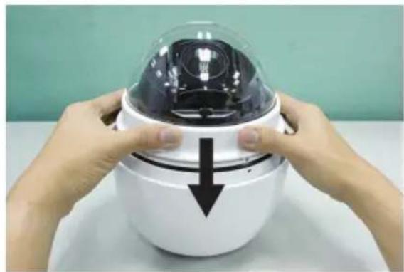
natural_image
Close-up of hands holding a white camera module with a black downward arrow, against a plain green background (no text or symbols visible)
The tiny protrusion on the dome cover must align with one of the four holes on the dome body.
Step 4
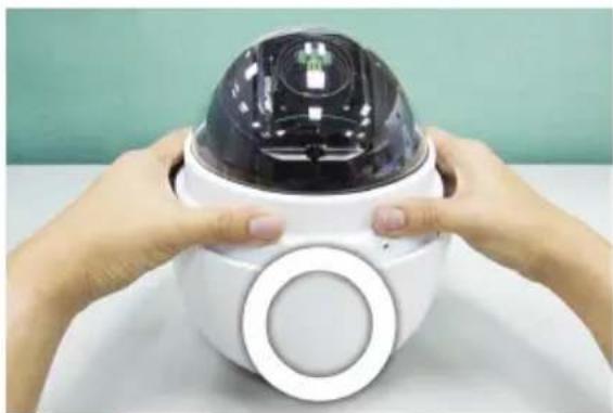
Gently pressure the dome cover downward with two hands on the side of it.
DO NOT press the cover, as shown in the figure; this might cause damage to the camera body.
natural_image
Close-up of hands holding a white smart security camera with a black dome and circular button (no text or symbols visible)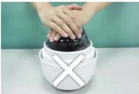
natural_image
Person holding a black dome-shaped object with a white 'X' symbol on the base, against a plain green background (no text or symbols)Step 5
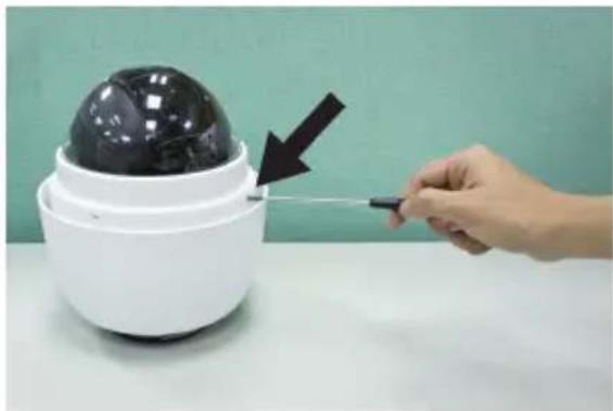
Use the M3 screw to screw the dome cover and camera body together.
natural_image
Hand using a screwdriver to adjust a black sphere on a white surveillance camera (no text or symbols visible)Step 6
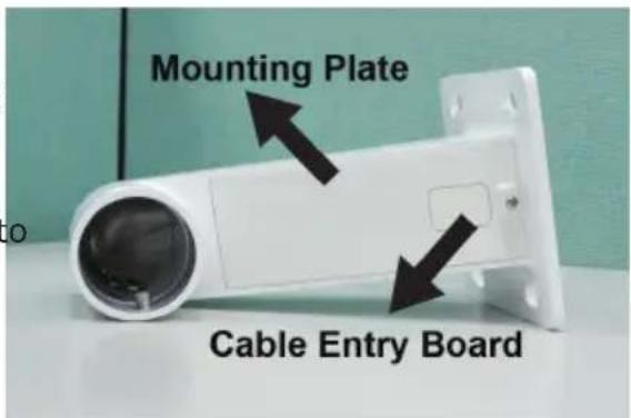
Make a cable entry hole on the wall to recess the cables. Otherwise, users could push up the Cable Entry Board on the Compact Pendent Mount's Mounting Plate to place the cables, as shown in the photo below.
Step 7
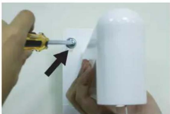
Fix the Compact Pendent Mount on the wall with proper screws and screw anchors. After this step, attach the Waterproof Rubber to the Outdoor Wall Mount.
natural_image
Close-up of hands using a screwdriver to apply a white plastic bottle onto a white surface, with an arrow pointing to the product (no text or symbols visible)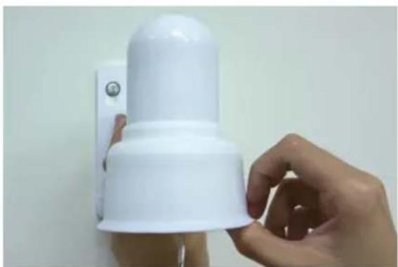
natural_image
Hand holding a white plastic wall-mounted device with a button, against a plain wall (no text or symbols visible)
Note
The screws and screw anchors don't attach in package.
Step 8
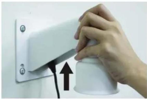
Pass the network and power cable through the Compact Pendent Mount
natural_image
Hand holding a white cylindrical object with a black upward arrow, next to a wall-mounted panel (no text or symbols visible)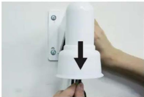
natural_image
Close-up of a hand holding a white spray bottle with a black downward arrow, against a plain wall (no text or symbols visible)
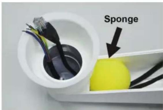
- The network cable doesn't attach in package.
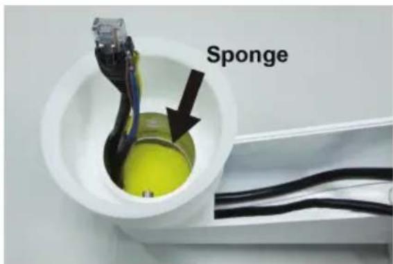
- Please block the cable entry hole with the supplied sponge to avoid insects entering the Pendent Mount. The sponge can be placed in two ways as shown in the illustrations below.
Step 9
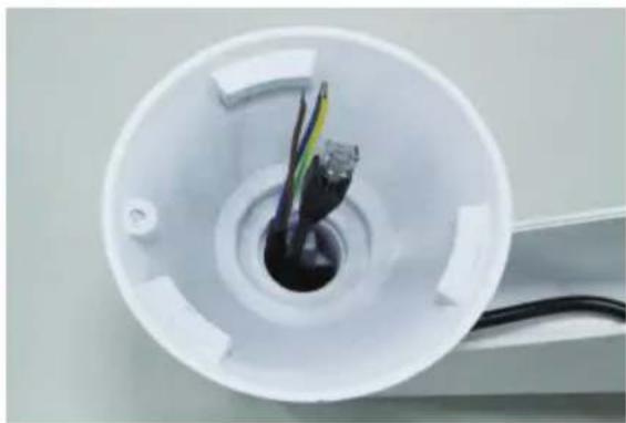
Thread the cables through the Outdoor Mount Kit and join the Outdoor Mount Kit to the Compact Pendent Mount with the supplied screws and washers. Then adjust the Waterproof Rubber to the joint.
natural_image
Interior view of a white cylindrical device with exposed wires and connectors (no text or symbols visible)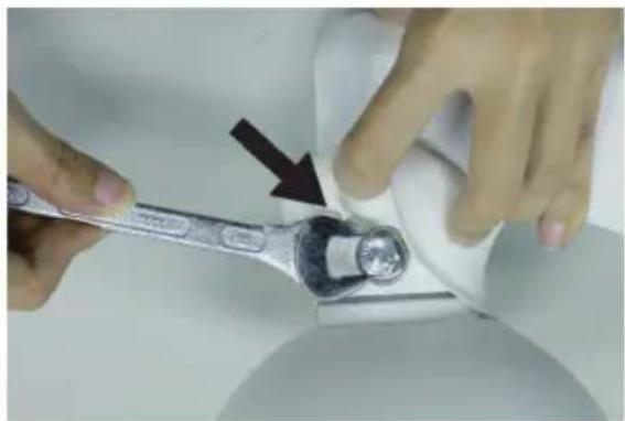
natural_image
Close-up of hands using a wrench to adjust a mechanical component (no text or symbols visible)Step 10
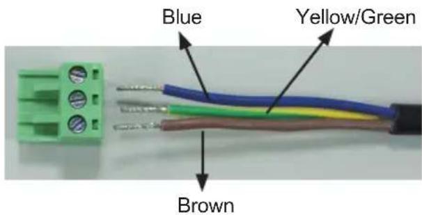
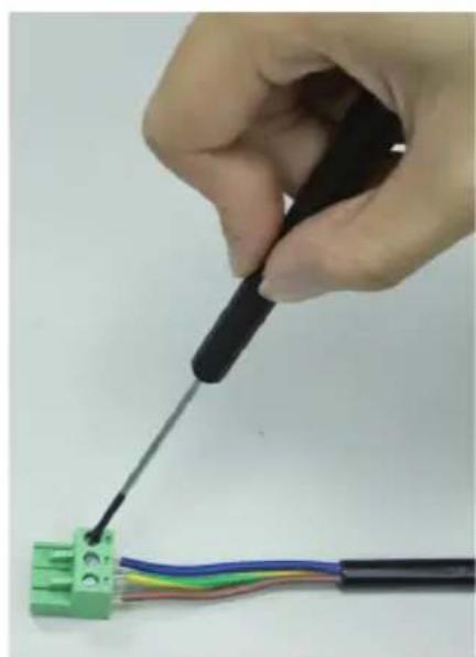
Connecting power wires of AC adapter with Power Input connector of data cable. Please check the color of power wire carefully, and screwed that with connector properly.
natural_image
Hand using a screwdriver to connect a green terminal block to a black cable (no text or symbols visible)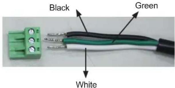

Caution
Wrong wiring could cause the device permanently damage.
Step 11
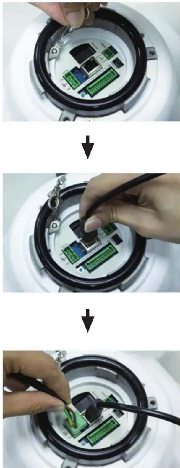
Use the safety hook hanging the camera, and connect the cables to the Dome Camera.
natural_image
Three-step installation of a microcontroller with an LCD module, showing the circuit board being inserted into a device (no text or symbols visible)Step 12
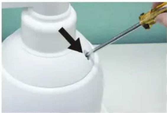
Assemble the Dome Camera to the Outdoor Mount Kit with the supplied M5 screw and washers.
natural_image
Close-up of a white bottle with a black arrow pointing to a small object on its side, being stirred by a tool (no text or symbols visible)
Note
Rotate the dome camera until the two screw holes which on the dome camera and the outdoor mount kit to be match.
Step 13
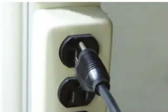
According to the practical local power voltage to adjust the power switch, and connect the power cord with adapter and power outlet.
Voltage Switch
natural_image
Close-up of a white electrical outlet plug with black connectors (no visible text or symbols)
Note
Use only the power adapter shipped with the unit to ensure correct functionality.
Step 14
Connecting the network cable with switch. The ICA-HM620 can be configured without external power if connecting to IEEE 802.3at High Power over Ethernet (PoE plus) switch.
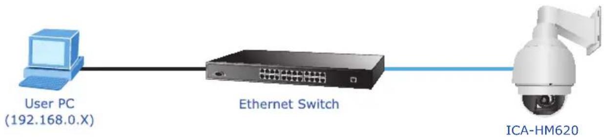
flowchart
graph LR
    A["User PC (192.168.0.X)"] --> B["Ethernet Switch"]
    B --> C["ICA-HM620"]

Note
If there is a need to operate the Heater, please plug the AC 24V cable into the Camera's Power Connector to power up the Camera instead. Heater can only be powered by the 24VAC adapter.
Step 15
Set your computer's IP address to 192.168.0.x, where x is a number between 1 to 253 (except 20 where is being used for the camera by default). If you don't know how to do this, please ask your network administrator.
Step 16
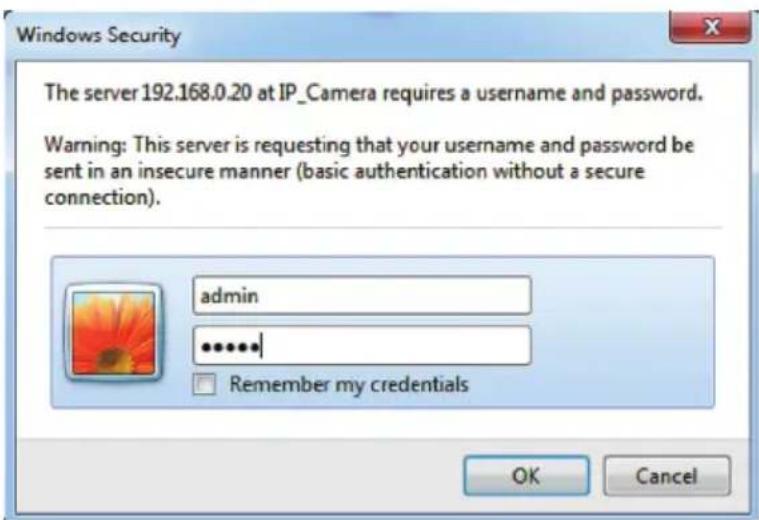
Use web browser (Internet Explorer 6.0 or above) to connect to 192.168.0.20 (type this address in the address bar of web browser).
You'll be prompted to input user name and password: admin / admin
Further Configuration
For detail configuration, please check user's manual on the bundled CD.
If you have any other questions, please contact the dealer where you purchased this product or you can contact PLANET directly at the following Email address: support_ica@planet.com.tw
Brand : Planet
Model : ICA-HM620
Category : Security Camera