VC-500WLN-II - Lamp Impact - Free user manual and instructions
Find the device manual for free VC-500WLN-II Impact in PDF.


| Product Type | Digital Monolight (Studio Flash) |
| Brand | Impact |
| Model | VC-500WLN-II |
| Maximum Flash Power | 500 Ws |
| Guide Number | 78 (ISO 100, with reflector) |
| Flash Duration | 1/800 to 1/1200 sec |
| Recycle Time | 0.2 to 1.6 sec (110-120 V, 60 Hz) |
| Power Output Range | Full to 1/32 in 1/10 stop increments (6 stops) |
| Modeling Lamp | 25 W COB LED |
| Modeling Lamp Modes | Proportional, Free, Off |
| Triggering Methods | 2.4 GHz wireless (32 channels), optical slave (7 modes), 1/4 in sync port |
| Wireless Range | 328 ft (100 m) |
| Color Temperature | 5600 K ±200 K |
| Power Source | 100-130 V AC, 50/60 Hz |
| Fuse Rating | 12.5 A (spare included) |
| Dimensions (with cap) | 12.6 × 5.1 × 5.1 in (32 × 13 × 13 cm) |
| Weight | 6.04 lb (2.74 kg) |
| Mount Type | 5/8 in receiver, Bowens mount, umbrella mount |
| Cooling | Fan cooled, adaptive thermal control |
| Auto Power Dump | Yes |
| Housing Material | Aluminum casting with textured coating |
| Included Accessories | Reflector, AC cable, flash tube (installed), spare fuse, protective cover, user manual |
| Safety | High voltage; no user-serviceable parts; use cotton gloves for flash tube; keep away from water/flammables |
| Care and Cleaning | Clean with soft, dry cloth only |
| Spare Parts and Repairability | User-replaceable flash tube and fuse; contact Impact for other repairs |
Frequently Asked Questions - VC-500WLN-II Impact
User questions about VC-500WLN-II Impact
0 question about this device. Answer the ones you know or ask your own.
Ask a new question about this device
Download the instructions for your Lamp in PDF format for free! Find your manual VC-500WLN-II - Impact and take your electronic device back in hand. On this page are published all the documents necessary for the use of your device. VC-500WLN-II by Impact.
USER MANUAL VC-500WLN-II Impact
natural_image
Exterior view of a Impact telescope with mesh lens and mounted base (no text or symbols on body)VC-500WLN-II
Digital Monolight
INSTRUCTIONS
Introduction
Thank you for choosing Impact.
This professional-grade studio lighting unit features a 500 Ws flash tube and an integrated 25 W COB LED modeling light. The monolight is constructed with a durable housing and boasts a lightning-fast 0.2 to 1.6-second recycle time, intelligent adaptive thermal control, and CMOS chip circuitry.
The powerful Impact Digital Monolight has an integrated 2.4 GHz multichannel wireless receiver. You can trigger the monolight from a distance of 328 feet when it's partnered with the VC-500WLXMT transmitter (included with kits only, sold separately). Paired with the unit's integrated group functions, you can arrange and digitally segment each of their remote devices as needed. Additionally, the flash's seven optical slave modes enable the device to communicate with your on-camera master flashes, seamlessly triggering up to five preflashes.
Box Contents
VC-500WLN-II
- Digital Monolight
- Reflector
- AC cable
-
Flash tube (installed)
-
Spare fuse (in fuse bay)
- Protective cover
- User manual
VC-500WL3KN-II
• Digital Monolight (×3)
- Reflector (×3)
• Air-cushioned light stand (×3)
- 40 in. umbrella—white with black backing (×3)
- 24 × 36 in. softbox with speed ring
- Wireless controller
- AC cable (×3)
- Flash tube (installed) ( × 3 )
- Spare fuse (in fuse bay) ( × 3 )
- Protective cover (×3)
- Kit case
- User manual
Precautions
• DANGER: high-voltage parts inside.
- There are no serviceable parts inside the unit. Only qualified service engineers should access the inside of the casing.
- If the flash tube becomes cracked or damaged in any way, replace immediately.
- Keep this product away from water and any flammable gases or liquids.
- Use only the correct, recommended voltage.
- Avoid rapid, high-power flashing.
- Excessive heat shortens the life span of flash tubes and internal components.
- If the unit is not used for two months, turn it on for 30 minutes, and fire the flash several times to charge the capacitors.
- Always remove the protective cap before plugging in or powering on the unit.
- Never operate the flash with the protective cap on.
• Make sure this product is powered off when plugging it into a power source.
- Turn off the power and unplug the power cord from the unit and wall when the monolight is not in use.
• Always attach the protective cap when transporting the unit. - Do not attempt to disassemble or repair this product. There are components inside that can produce a hazardous electric shock.
- Handle this product with care.
- Do not stare at the lights when they are powered on.
- Clean this product with only a soft, dry cloth.
• Always wear cotton gloves when handling the flashtube. - Keep this product away from children.
• Make sure everything is secure before proceeding.
• Make sure that this product is intact and that there are no missing parts before use. - Do not block, cover, or restrict the air vents when the unit is in use.
• All images are for illustrative purposes only.
Overview
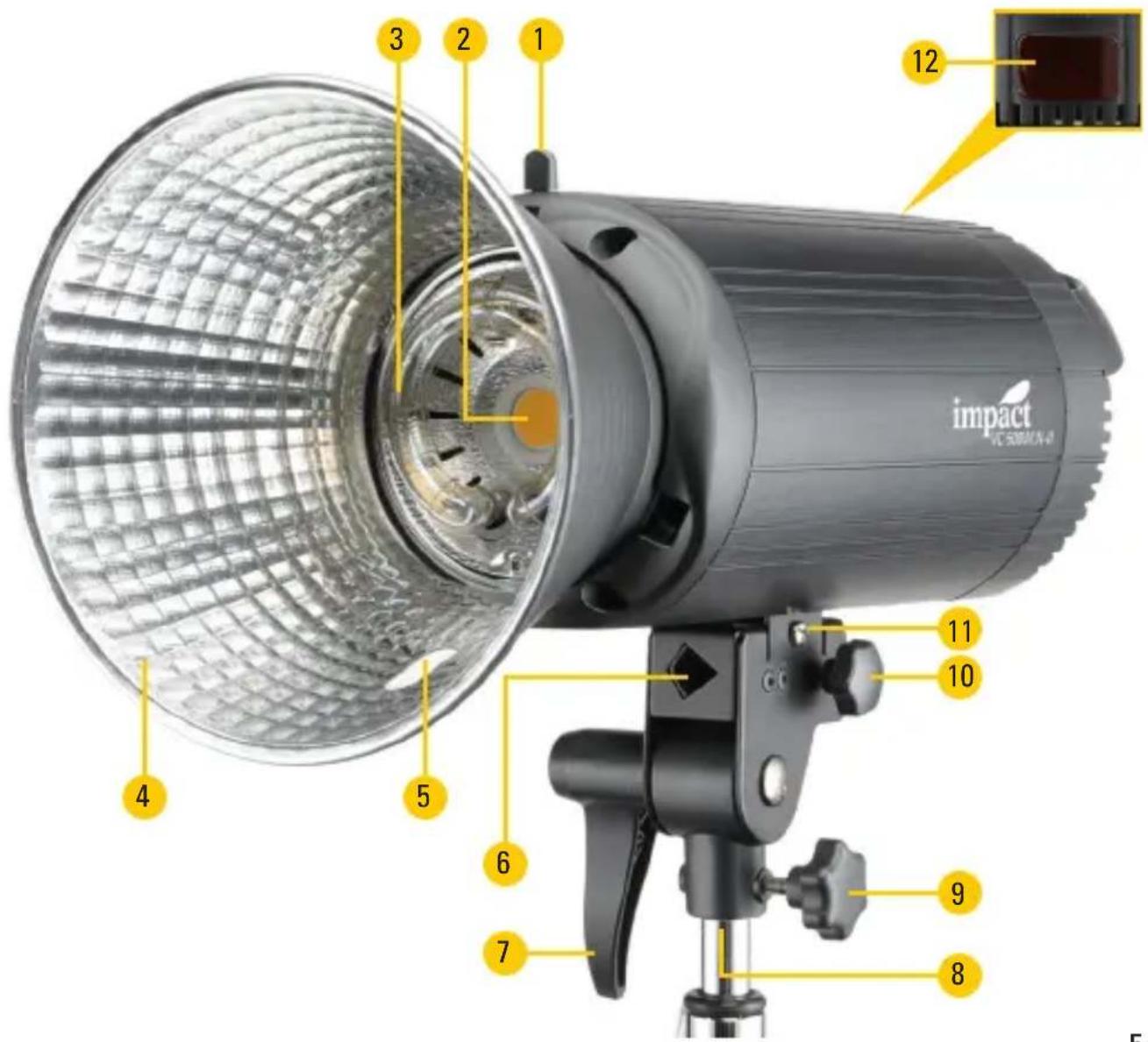
Front
- Mount release
- Modeling light
- Flashtube
- Reflector
- Umbrella hole
-
Umbrella mount
-
Tilt lock
- 5/8 in. mount
- Locking knob
- Umbrella mount locking knob
- Balance adjustment screw
- Optical sensor
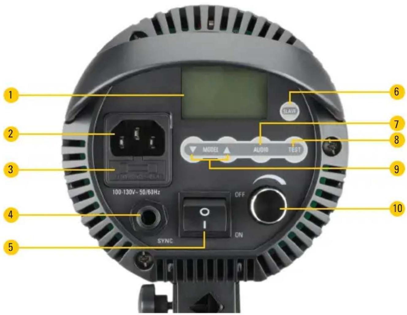
Back
- LED screen
- Power input jack
- Fuse bay
- 1/4 in. (6.35 mm) sync port
- Power switch
-
Slave mode button
-
Audio button
- Test button
- Up and down buttons
- Modeling light and power output adjustment dial
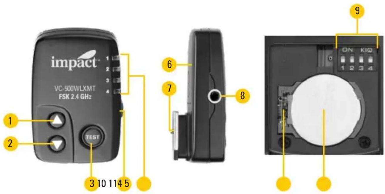
Remote Guide (Kits Only)
Top
- Up button
- Down button
- Test button
- Group selector button
- Group indicators
Side
- Battery compartment cover
- Hot-shoe mount
- 3.5 mm sync port
Battery Compartment
- Channel DIP switches
- Battery clasp
- Battery slot with CR2032 battery installed
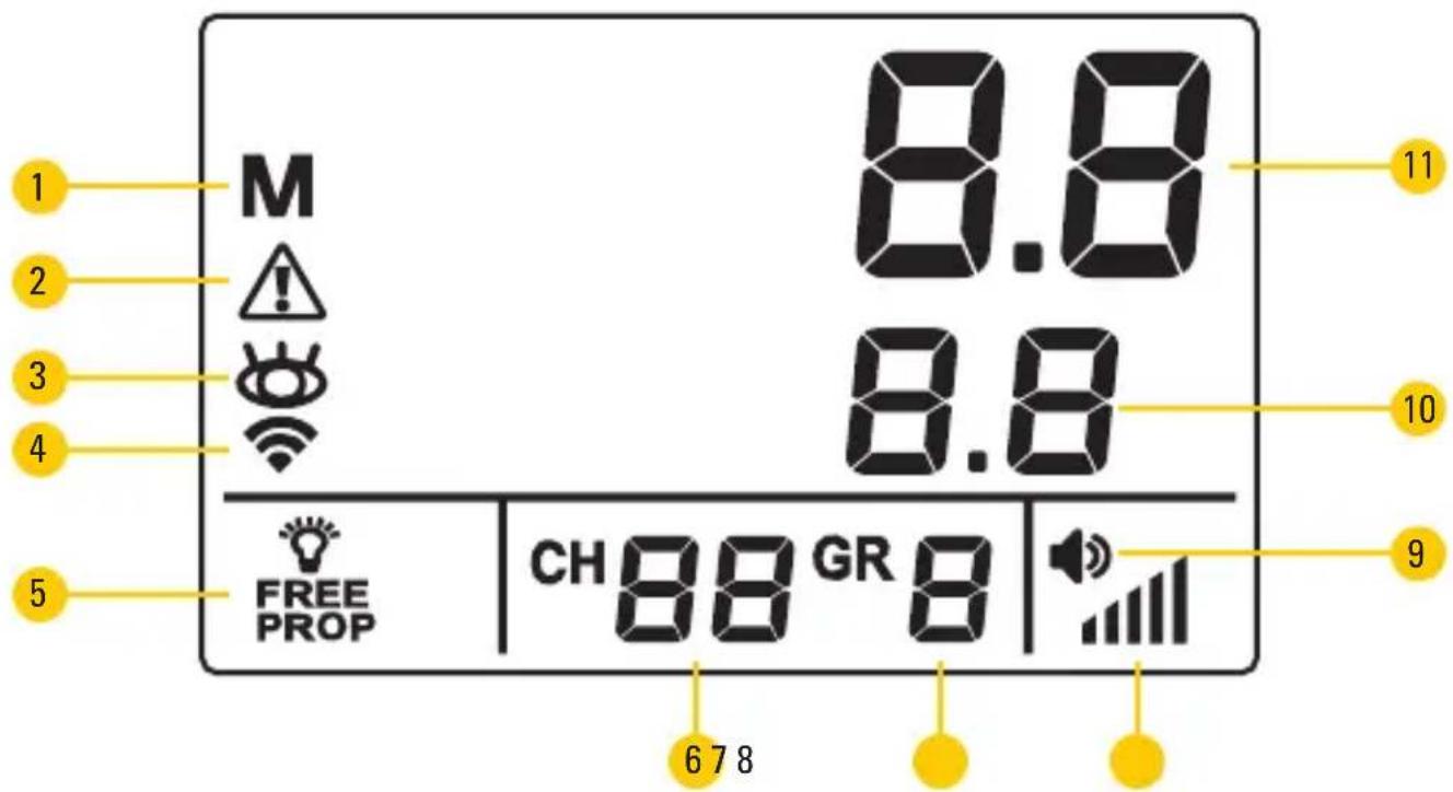
Control Panel Display Screen
- Manual flash indicator
- Overheating warning
- Slave/Photocell on/off indicator
- Wireless radio signal indicator
- Modeling lamp mode indicator
-
Channel
-
Group
- Flash recycle indicator
- Audio indicator
- Modeling lamp output power
- Flash output power
Setup
Preparing for Use
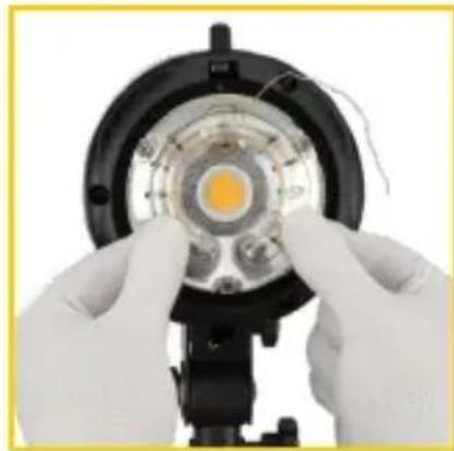
The Impact Digital Monolight includes a preinstalled flash tube. Be careful not to touch the flash tube with your bare hands, since this could cause damage to it. Use cotton gloves or a soft, dry cloth when touching or handling the flash tube. See Installation and Replacement Guide on page 23.
Remove the protective cap before plugging in or powering on the unit. Push back the mount release, turn the cap counterclockwise, and pull the cap from the mount.
Attach the reflector by aligning the lugs and making sure the umbrella hole is on the bottom. Push back the mount release, fully insert the reflector, and turn it clockwise. You'll hear it click into place.
natural_image
Close-up of gloved hands holding a circular LED component with visible internal structure (no text or symbols)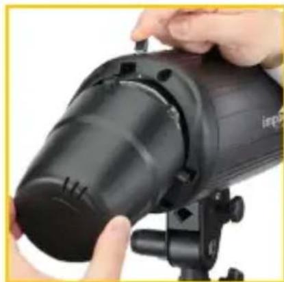
natural_image
Close-up of hands installing or adjusting a black industrial lamp on a tripod stand (no visible text or symbols)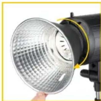
natural_image
Close-up of a black studio lighting fixture with a circular glass filter, being handled by a hand (no text or symbols visible)Mounting Accessories
5/8 in. mounting receiver
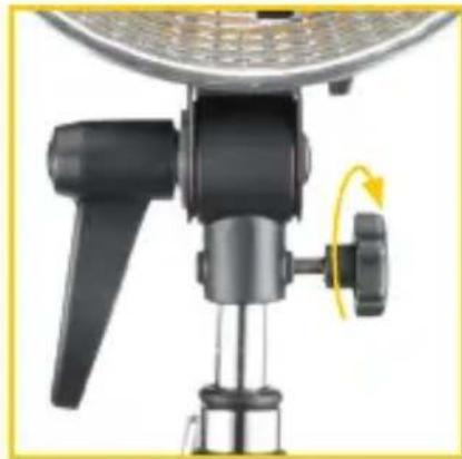
The Impact Digital Monolight has a standard 5/8 in. receiver with tilt lock and tightening knob. Place the light onto a stand with a standard 5/8 in. stud.
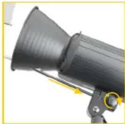
Turn the locking knob to secure. Turn the tilt lock counterclockwise to adjust the tilt of the monolight. Turn the knob clockwise to secure the monolight in place.
natural_image
Close-up of a mounted device with a yellow rotation arrow indicating rotational motion (no text or symbols visible)Bowens mount
The Digital Monolight has a Bowens mount for light-modifying accessories. This can be used with optional add-ons such as speed rings for softboxes. The included umbrella lines up with the umbrella mount.
Always turn the monolight's power off before attaching or removing accessories. Insert the accessory into the Bowens mount and rotate clockwise until it clicks. To remove it from the mount, hold down the mount release and rotate the accessory counterclockwise.
Umbrella Mount
To mount an umbrella to the monolight, first attach the reflector using the above instructions. Then run the umbrella rod through the reflector's umbrella hole and into the monolight's umbrella mount. Secure the umbrella by tightening the umbrella locking knob.
Note: Umbrellas are included only with two- and three-light kits. Umbrellas can be purchased separately for the VC-500WLN-II.
natural_image
Close-up of a black industrial lamp with yellow directional arrows indicating motion (no text or symbols visible)Balance Adjustment
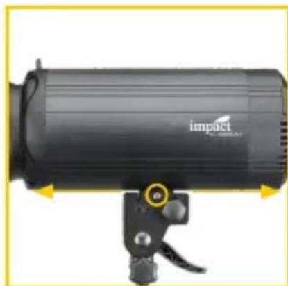
Sliding tracks on the bottom of the monolight let you adjust the light's balance point when large and heavy accessories are attached.
Use a Phillips screwdriver to loosen the slider screw, as pictured. Do not completely remove the screw.
Slide the monolight to the preferred balance point. For example, for heavier accessories, slide the monolight back on the tracks so the balance point is closer to the front of the light. This will prevent the monolight from tipping forward.
natural_image
Close-up of a black industrial lamp with a yellow circular button and handle (no visible text or symbols)Tighten the screw until secure.
Connecting Your Camera to the Monolight
The Impact Digital Monolight has two triggering options.
Sync Cord (Optional Accessory)
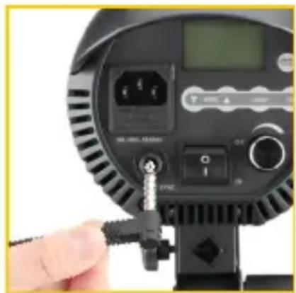
The back of your monolight has a 1/4 in. (6.35 mm) sync input, which is used for a wired connection between your camera and the flash unit.
Plug a sync cable's 1/4 in. connector into the monolight and the PC connector into your camera. Use an adapter (not included) if your camera does not have a PC port.
natural_image
Close-up of a black studio lighting device with adjustment knobs and control buttons (no visible text or symbols)Wireless
Note: The remote is included only with the three-light kit. The VC-500WLXMT remote can be purchased separately.
The Impact Digital Monolight has an integrated 2.4 GHz multichannel wireless receiver. Using the included transmitter, you can wirelessly trigger your flash unit from up to 328 feet (100 m) away. Line-of-sight is not required for your monolights to communicate with the transmitter.
For instructions on how to operate your monolights with the transmitter, refer to the transmitter's user manual or the instructions in this manual.
Note: You can attach your own wireless triggering system receiver to the Digital Monolight via the sync port.
Powering the Monolight
The Impact VC-500WLN-II Monolight is designed to operate with a 100–130 V, 50/60 Hz AC power. Before powering your monolight, first plug the AC cable into the flash's AC input, and then plug it into the wall socket.
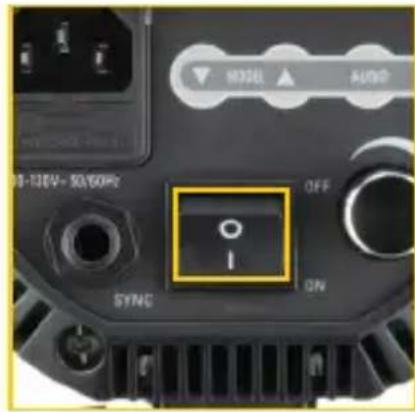
Press the power switch to turn the unit on. The display will show the current flash power setting.
Note: The monolight saves all of the previous flash and modeling light settings. All of these settings will be active when powering on.
Important! Impact recommends charging the monolight's capacitors for one hour before its initial use, and after an extended period of inactivity (more than two weeks). If the unit is left unused for an extended period of time, or if the unit has been mostly used at low power, set the monolight output to full power and leave it plugged in and switched on (with the modeling lamp off) for at least 30 minutes. This will help preserve the life of the capacitors.
Operation
Setting the Monolight's Power Output
The Impact Digital Monolight's flashtube has a 6-stop power range, represented by a 1–6 (f-stop) numbered scale on the display. The adjustment knob changes the monolight output value by 0.1 f-stop increments.
To increase or decrease the power output of the monolight, turn the adjustment dial. This will adjust both the monolight and modeling lamp (unless the modeling lamp is set to independent mode on or off). For information on adjusting the modeling lamp power output, refer to Setting the Modeling Light Power Output below.
When decreasing the power of the flash, the power output setting on the display will blink until the capacitors release the accumulated energy (auto power dump). To speed up the process, press the TEST button to fire the flash after the output has been decreased.
| Setting Power | |
| 6.0 Full | |
| 5.0 1/2 | |
| 4.0 1/4 | |
| 3.0 1/8 | |
| 2.0 1/16 | |
| 1.0 1/32 | |
Setting the Modeling Light Power Output
The VC-500WLN-II Monolight has an integrated LED modeling light. The modeling light's power output is represented on the display by a 1–6 numbered scale that can be adjusted by 0.1 increments.
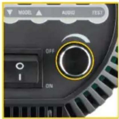
Press the output adjustment dial repeatedly to cycle through the modeling light's three operating modes:
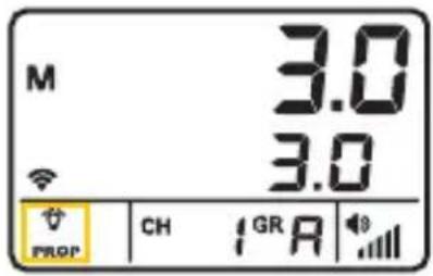
- In proportional mode, use the adjustment dial to increase or decrease the flash power. The modeling light brightness will increase or decrease incrementally with the flash power.
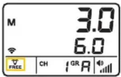
- In free mode, use the and buttons to adjust the modeling light brightness independently of the flash output power. Each button press will change the power output of the modeling light by 0.1 increments. Press and hold the or buttons to rapidly increase or decrease the value.
- Off mode turns the modeling light off. No modeling light icons appear onscreen.
The modeling light can be used as a recycle indicator. When the audio function is deactivated (see Audio Button on page 18), the modeling light will turn off when the flash is fired, and it will turn on again to indicate that the capacitors have recharged. When the audio function is active, the modeling light will not turn off when the flash is fired.
Slave and Preflash Settings
The Impact Digital Monolight has seven optical slave/preflash modes.
Press the slave button to activate slave mode. The slave indicator light appear on the display. Press it again to turn it off.
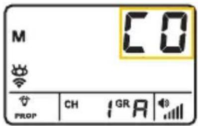
To adjust the preflash settings, press and hold the slave button for four seconds. Use the ▲ and ● buttons to toggle between preflash settings.
CO: Using your master flash, release a test exposure. The monolight will automatically memorize the amount of preflashes fired.
C1: The monolight will flash when it detects another flash.
C2: The monolight will trigger after one preflash.
C3: The monolight will trigger after two preflashes.
C4: The monolight will trigger after three preflashes.
C5: The monolight will trigger after four preflashes.
C6: The monolight will trigger after five preflashes.
Once the preflash is set, press and hold the Slave button for 4 seconds to return to the main screen.
Setting Channels and Groups
The Impact Digital Monolight has an integrated 2.4 GHz multichannel radio receiver. The three-light kit (VC-500WL3KN-II) includes a wireless radio transmitter for remote triggering.
See page 20 for instructions on using the remote with your monolights.
To access the channel and groups pages, press and hold the Slave button for 4 seconds until the preflash page appears. Press the slave button repeatedly to cycle through preflash, channel, and groups pages.
Once the channel and group are set, press and hold the Slave button for 4 seconds to return to the main screen.
Setting a Channel
Set your devices to the same channel to trigger them all at the same time. This also aids in avoiding radio interference from other devices in the area.
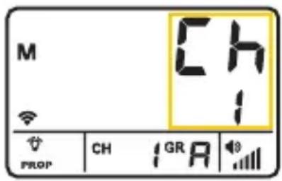
- Press the Slave button repeatedly to select the channel or group screen.
- Use the o▲ buttons to select a channel.
- Make sure the remote is set to the same channel. See Remote Instructions on page 20.
Setting a Group
Groups are effective for independently adjusting selected lights in a multi-flash setup. Setting lights to groups let you set brightness of key, fill, and hair lights individually.
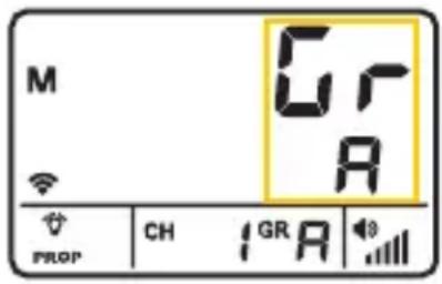
- Press the Slave button repeatedly until the group selection screen appears.
- Use the ▲ buttons to select a group.
- Press and hold the Slave button for 4 seconds to return to the main screen.
Other Functions and Protective Features
Audio Button
When the audio icon is onscreen, the monolight will emit a beep to indicate that the capacitors have recharged. To turn this function off, press the audio button. The icon will turn off. Press the audio button again to reactivate the function.
Note: When the audio function is disabled, the modeling light will act as a recycle indiactor. When the flash is fired, the modeling light will turn off until the capacitors have recharged, and then turn on again.
Overheating Protection
After a long shooting session at a high power output, the recycling time of the flash will increase automatically until the flash cools to a safe level. Once cooled, it will begin operating as usual.
Overvoltage and Overcurrent Protection
The flash is protected against unstable voltages. Overcurrent protection is useful when using a power generator (gasoline or electric) to power the flash unit.
Error Codes
In the event of a malfunction, the display will show a blinking error code. In addition, error codes E2 and E3 are accompanied by a beep warning.
E1: Temperature transducer problem. Turn the unit off immediately and contact Impact customer service.
E2: This error code can appear after a long shooting session at high output or rapid sequence. Turn off the flash unit and allow it to cool for 30 minutes.
E3: This error code will appear when the internal voltage of the flash is too high. Turn off the power immediately. After approximately 5 minutes, turn the flash back on. If the error is still displayed on the LED screen, turn off the monolight and contact Impact customer service.
E4: This error code will display when the charge circuit is wrong. Turn the unit off immediately and contact Impact customer service.
Remote Instructions
Impact's VC-500WL3KN-II three-light kit comes with a 2.4 GHz transmitter that enables the user to control and trigger the studio flash remotely. (The VC-500WLXMT transmitter can be purchased separately.)
Mount the transmitter onto your camera's hot shoe or connect it using the included 3.5 mm to PC sync cord.
Adjusting Flashtube Power
Press the ▲ or button on the remote to adjust the power output of the flashtube. Each push of the button will adjust the output in 0.1 increments.
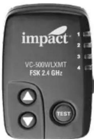
Set the modeling light to proportional mode (see page 15), and the buttons will also adjust the modeling light power in 0.1 increments.
Operating the Modeling Light
To turn on the modeling light, press and hold the ▲button for three seconds. The modeling light will automatically set to Free mode.
If the modeling light is set to proportional mode, press and hold the ▲button to switch to free mode.
Once free mode is activated, immediately press the ▲ and buttons to adjust the modeling light power in whole increments.
After three seconds of inactivity, the ▲ and buttons return to the function of adjusting the flash output in 0.1 increments.
Turn off the modeling light by pressing and holding the ▼button for three seconds.
Channels
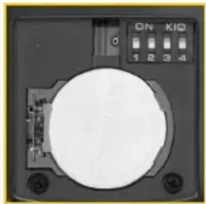
This studio flash has a multichannel radio receiver, which can be triggered using the included transmitter. To adjust the channel settings on the remote, first remove the battery compartment door. Set the device to your required channel, using the chart below as a guide.
natural_image
Close-up of a circular electronic device with indicator lights and ports (no readable text or symbols)Note: White represents the DIP switch button.
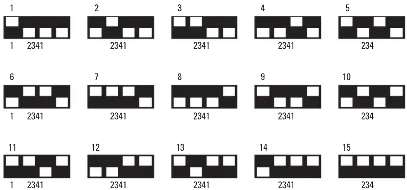
Note: The channel setting on the monolight and the transmitter must match in order to wirelessly trigger the flash, adjust flash power, and turn on/off the modeling lamp.
Groups
The Impact Digital Monolight has multiple groups, used to segment remote devices. Press the group selector button repeatedly to select the group that corresponds to the lights you want to trigger.
Note: The group setting on the monolight and the transmitter must match in order to wirelessly trigger the flash, adjust flash power, and turn on/off the modeling lamp.
Testing the Monolight
Press the transmitter's test button to test-fire the monolight.
Replacing the Battery (CR2032)
To install a battery into the wireless trigger, first remove the battery compartment door. Remove the spent battery by holding back the clasp and pulling the battery out. Insert the new battery under the clasp, using the correct orientation, and snap the other side into place. Reinstall the battery compartment door.
Installation and Replacement Guide
The Flash Tube
The Impact Digital Monolight's flash tube is user-replaceable. To replace the flash tube, follow these steps:
- Discharge the flash unit by pressing the test button.
- Turn off the monolight and unplug the power cable from the flash unit and power source.
-
After 30 minutes, remove any accessories connected to the unit.
-
Wear a pair of cotton gloves or hold a soft, dry cloth, and use a pair of needle-nose pliers to carefully unhook the retention spring loop of the flash tube. Make sure it is disengaged from the flash tube.
-
Once it is unhooked, grip the base of the flash tube on each side and carefully pull it from the monolight.
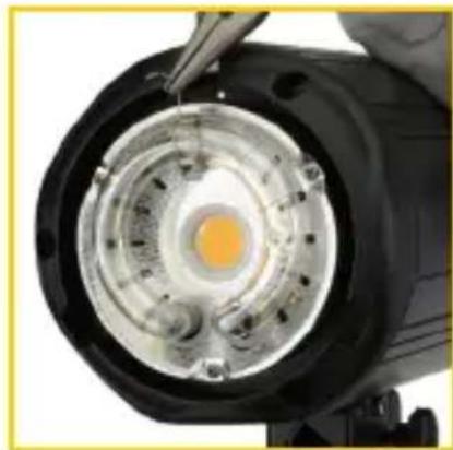
natural_image
Close-up of a black cylindrical device with a glowing orange core and internal components, being handled by tweezers (no visible text or symbols)-
Pick up the new flashtube and push its pins into the sockets by applying firm, even pressure at the base.
-
With needle-nose pliers, hook the retention spring over and above the flash tube.
-
Reinsert the modeling lamp, then any other accessory to the monolight.
Replacing the Fuse
The Impact Digital Monolight comes with two fuses: one installed and one spare. Both are located within the fuse bay. To remove the fuse housing from the fuse bay and replace the fuse, use the following instructions:
- Ensure the monolight is powered off and unplugged.
- Insert a slotted screwdriver into the nook on the flat side of the AC jack, and gently pry out the fuse housing.
- The fuse located within the housing is the one the monolight is using when it is powered on. To replace the fuse, remove it from the box.
- Replace it with the included spare.
- Reattach the fuse holder to the fuse bay to complete the process.
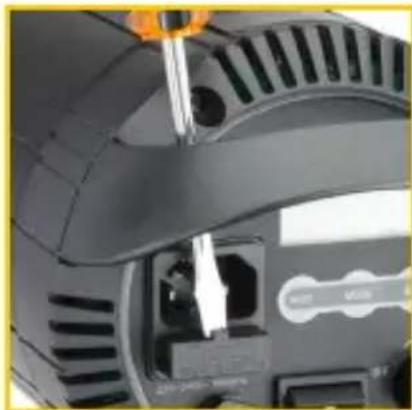
natural_image
Close-up of a mechanical device with a screwdriver inserted, showing internal components and no visible text or symbols.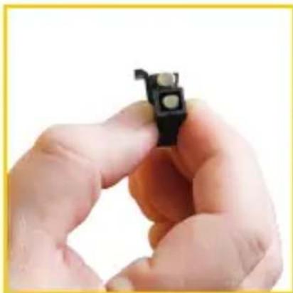
natural_image
Close-up of hands holding a small black electronic component (no visible text or symbols)Specifications
Power Output 500 Ws
Guide Number 78
Output Control Range Full to 1/32 in 1/10 increments
Recycle Time (110\~120 V 60 Hz) 0.2 to 1.6 sec.
Flash Duration 1/800 to 1/1200 sec.
Flash Ready Indicator Visible or audible confirmation
Power Range 6 stops
Modeling Lamp Output 25 W LED
Modeling Lamp Control Proportional, Independent, Off
Triggering Method 16-channel wireless transmitter (included with
kits only)
Direct-connect 1/4 in. phono plug to PC cord
(optional accessory)
Optical slave with preflash settings.
Effective Wireless Distance Range 328 ft. (100 m)
Battery Replacement for Transmitter CR2032 3 V
Color Temperature 5600 K (±200 K)
Flash Tube User-replaceable plug-in tube
Trigger Voltage DC 5 V
Sync Cable Input 1/4 in. (6.35 mm)
Slave Settings
Red-eye reduction, synchronous
Integrated Receiver Frequency 2.4 GHz
Channels
32
| Cooling Fan Yes | |
| Touch Pad Controls Yes | |
| Auto Power Dump Yes | |
| Adaptive Thermal Control Yes | |
| Housing Material Aluminum casting with textured coating | |
| Mount Type S-mount, umbrella mount | |
| Power Source 100 to 130 V 50/60 Hz | |
| Circuit Protection 12.5 A | |
| Length of Included AC Cord 13 ft. (4 m) | |
| Weight 6.04 lb. (2.74 kg) | |
| Dimensions (with protective cap) | 12.6 × 5.1 × 5.1 in. |
| (L × H × W) | (32 × 13 × 13 cm) |
FCC Disclaimer:
This device complies with Part 15 of the FCC Rules. Operation is subject to the following two conditions:
- This device may not cause harmful interference, and
- This device must accept any interference received, including interference that may cause undesired operation.
One-Year Limited Warranty
This Impact product is warranted to the original purchaser to be free from defects in materials and workmanship under normal consumer use for a period of one (1) year from the original purchase date or thirty (30) days after replacement, whichever occurs later. The warranty provider's responsibility with respect to this limited warranty shall be limited solely to repair or replacement, at the provider's discretion, of any product that fails during normal use of this product in its intended manner and in its intended environment. Inoperability of the product or part(s) shall be determined by the warranty provider. If the product has been discontinued, the warranty provider reserves the right to replace it with a model of equivalent quality and function.
This warranty does not cover damage or defect caused by misuse, neglect, accident, alteration, abuse, improper installation or maintenance. EXCEPT AS PROVIDED HEREIN, THE WARRANTY PROVIDER MAKES NEITHER ANY EXPRESS WARRANTIES NOR ANY IMPLIED WARRANTIES, INCLUDING BUT NOT LIMITED TO ANY IMPLIED WARRANTY OF MERCHANTABILITY OR FITNESS FOR A PARTICULAR PURPOSE. This warranty provides you with specific legal rights, and you may also have additional rights that vary from state to state.
To obtain warranty coverage, contact the Impact Customer Service Department to obtain a return merchandise authorization ("RMA") number, and return the defective product to Impact along with the RMA number and proof of purchase. Shipment of the defective product is at the purchaser's own risk and expense.
For more information or to arrange service, visit www.impactstudiolighting.com or call Customer Service at 212-594-2353.
Product warranty provided by the Gradus Group.
www.gradusgroup.com
Impact is a registered trademark of the Gradus Group.
© 2023 Gradus Group LLC. All Rights Reserved.
- Introduction
- Thank you for choosing Impact.
- Box Contents
- VC-500WLN-II
- VC-500WL3KN-II
- Precautions
- Overview
- Front
- Back
- Remote Guide (Kits Only)
- Top
- Side
- Battery Compartment
- Control Panel Display Screen
- Setup
- Preparing for Use
- Mounting Accessories
- 5/8 in. mounting receiver
- Bowens mount
- Umbrella Mount
- Balance Adjustment
- Connecting Your Camera to the Monolight
- Sync Cord (Optional Accessory)
- Wireless
- Powering the Monolight
- Operation
- Setting the Monolight's Power Output
- Setting the Modeling Light Power Output
- Slave and Preflash Settings
- Setting Channels and Groups
- Setting a Channel
- Setting a Group
- Other Functions and Protective Features
- Audio Button
- Overheating Protection
- Overvoltage and Overcurrent Protection
- Error Codes
- Remote Instructions
- Adjusting Flashtube Power
- Operating the Modeling Light
- Channels
- Groups
- Testing the Monolight
- Replacing the Battery (CR2032)
- Installation and Replacement Guide
- The Flash Tube
- Replacing the Fuse
- Specifications
- FCC Disclaimer:
- One-Year Limited Warranty
Brand : Impact
Model : VC-500WLN-II
Category : Lamp