
Beta 8.70 DSP - Receiver Black Hydra - Free user manual and instructions
Find the device manual for free Beta 8.70 DSP Black Hydra in PDF.


| Product Type | Car Audio Receiver (Amplifier with DSP) |
| Model | Beta 8.70 DSP |
| Brand | Black Hydra |
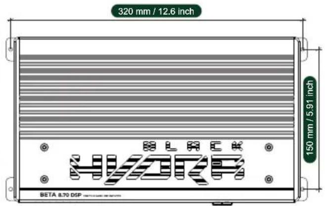
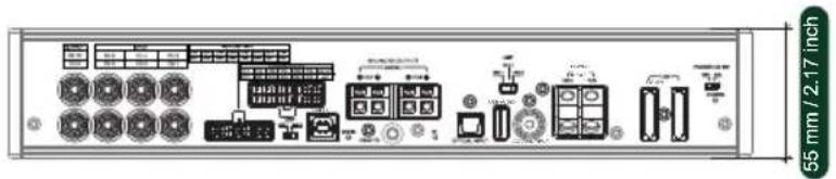
| Dimensions (LxWxH) | 312 x 180 x 55 mm (12.28 x 7.1 x 2.17 in) |
| Weight | Approx. 2.5 kg (estimate) |
| Power Supply | 10-17 V DC, 2 x 35 A blade fuses |
| Amplifier Class | AB (6 channels) + D (2 channels) |
| Output Power (RMS) | 6 x 70 W (4 Ohm) + 2 x 90 W (4 Ohm); 6 x 80 W (2 Ohm) + 2 x 110 W (2 Ohm); 1 x 220 W bridged (4 Ohm) |
| Number of Channels | 8 (6 AB + 2 D) |
| Inputs | 6 RCA, 8 High-Level, 1 Optical (TOSLINK), 1 Coaxial (S/PDIF), 1 USB Audio, 1 USB PC, 1 Bluetooth (5.0 with AptXHD) |
| Outputs | 8 Speaker Outputs, 2 RCA, 1 REM OUT |
| DSP | ADAU1452, 24-bit / 96 kHz ADC/DAC, 31-band parametric EQ per channel, crossover (HPF/LPF 20-20kHz, 6-48 dB/Oct), time alignment (0-20ms), phase adjustment |
| Frequency Response | 20 - 20,000 Hz |
| Total Harmonic Distortion (THD) | AB: <0.015% (1 kHz), D: <0.05% (1 kHz) |
| Signal-to-Noise Ratio | ≥100 dB |
| Input Sensitivity (Low Level) | 0.78 - 6 V RMS |
| Input Sensitivity (High Level) | 6.5 - 15 V RMS |
| Bluetooth | Bluetooth 5.0 with AptXHD, device name: BETA8.70 DSP |
| PC Software | Windows 10/11, no installation required (portable) |
| Remote Control | DRC (Digital Remote Control) sold separately |
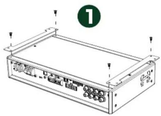
| Mounting | Standard car audio mounting brackets included |
| Warranty | 12 months from date of purchase |
| Service Life | 12 months from date of purchase |
| Disposal | Must be disposed of according to local regulations for electronic waste |
| Maintenance | Clean with dry cloth; do not use liquids. Replace fuses only with same type (35A blade). |
| Safety | Installation by qualified personnel only; disconnect power before servicing |
Frequently Asked Questions - Beta 8.70 DSP Black Hydra
User questions about Beta 8.70 DSP Black Hydra
0 question about this device. Answer the ones you know or ask your own.
Ask a new question about this device
Download the instructions for your Receiver in PDF format for free! Find your manual Beta 8.70 DSP - Black Hydra and take your electronic device back in hand. On this page are published all the documents necessary for the use of your device. Beta 8.70 DSP by Black Hydra.
USER MANUAL Beta 8.70 DSP Black Hydra
natural_image
Line drawing of a rectangular electronic device with ports and connectors, labeled with number 1 (no text or symbols on the device itself)
natural_image
Line drawing of a server rack with ports and connectors, no text or symbols present
APPLICATION OF CONNECTORS AND CONTROLS....31
CONNECTION TO POWER SOURCE....32
REMOTE ACTIVATION OF THE AMPLIFIER....33
SIGNAL SOURCES CONNECTION....34
SPEAKERS WIRING DIAGRAMS....39
PC CONNECTION....42
WINDOWS PC SOFTWARE OVERVIEW....43
SPECIFICATIONS....49
MAINTENANCE AND UTILIZATION....50
First of all, we would like to congratulate you on choosing the BLACK HYDRA car audio amplifier!
On these pages, you will not find an absolutely accurate justification for the superiority/uniqueness of our audio systems, because music can only be assessed by emotions gained from listening. Black Hydra audio systems will satisfy you by the excellent sound quality rather than with the numbers. It will give you true emotions of the listening to your favorite music, incomparable with the evaluation of «dry» specifications written on paper in silence.
During building of audio system based on Black Hydra components we recommend that you use only high quality components in each of its links, to achieve the most accurate transmission of music material. Remember the quality of any system is determined by its weakest link.
Technical specifications of Black Hydra amplifiers are equal and correspond to the most of best industry representatives, while at the same time surpassing them in subjective estimations of sound quality.
Perfectly honed circuit solutions with excellent architecture, combined with the use of components of the highest grade, made it possible to make our product unique, capable of transmitting the finest nuances of the sound of your favorite compositions without distortions and with high details.
The power supplies of all amplifier models are designed with an impressive reserve, which allows achieving maximum output even at the upper limits of the declared power level.
By placing individual parts of the circuit on subboards the lengths of the conductors were reduced and optimized, which completely eliminated interference between channels and as a result improved crosstalk attenuation, making it possible to achieve greater clarity of images in the sound stage.
JUST ENJOY

EXTERNAL SIZE

MOUNTING SIZE
HOW TO MOUNT
natural_image
Line drawing of a rectangular electronic device with ports and mounting brackets, no text or symbols present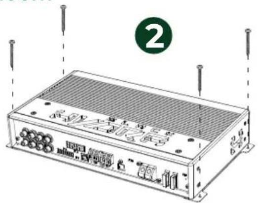
natural_image
Line drawing of an electronic device chassis with labeled ports and connectors (no text or symbols beyond labels)DRC installation (sold separately)
SIZE
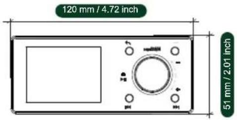
17 mm / 0.07 inch

HOW TO MOUNT


1 OUTPUT – signal output, RCA jacks
2 SPEAKERS OUTPUTS – speakers connection terminals, AB class amplifier
3 – LED for active preset (green-blinking) MODE
4 SPEAKERS OUTPUTS – speakers connection terminals, D class amplifier
5 AMP – amplifier ground selection switch
6 POWER INPUT – power supply terminals
7 POWER ON SW - HIGH/ACC - selection of amplifier switch on mode
8 – signal input, RCA jacksINPUT
9 HIGH-LEVEL INPUT – high-level signal input
10 - DSP ground selection switchDSP
11 – PC connection interfaceUSB PC
12 REMOTE – input for connection of the DRC remote control
13 BT – LED for bluetooth operation (blue)
14 OPTICAL INPUT – signal input, optical
15 USB AUDIO – signal input, USB audio
16 COAXIAL INPUT – signal input, coaxial
17 POWER – LED for operation (blue) / LED for protection (red)
Black Hydra car amplifiers are designed to operate in 12-volt systems with a permissible voltage of 10-17V. A significant voltage deviation from operating limits can lead to incorrect operation of the device or to its complete failure.
We recommend the use power cables made of oxygen-free copper, with properly selected diameter that allows the transmission of an electrical signal with minimal loss. If the distance from the battery to the amplifier exceeds 4m, we recommend using larger diameter cables to prevent loss of sound quality.
Start power supply wiring by connecting the power cable to the negative polarity (minus), grounding it at the nearest point to the amplifier at the car body. Connect the positive power cable directly from the corresponding battery terminal.
To avoid problems in the electrical and electronic systems of your car, the installation and connection of the power supply to the amplifier should be carried out only by qualified personal! (Fig.1)

Amplifier has 2 pcs of blade type protection fuse 35 A. In case you need to replace the fuse, use only the same type and value as the original. (Fig. 2)
The amplifier supports two methods of remote activation:
To select desired turn on method please use power on switch at the amplifier's side panel.

- By high level signal input (HIGH): by connecting the high level output signal of an OEM source to the high level input terminals of the amplifier and setting the POWER ON SW switch to HIGH. In this way the auto turn on function is activated to turn on the amplifier when high level signal is present. By setting the POWER ON SW switch to ACC, this function is disabled.

- By remote input (ACC): by connecting the remote input terminal ACC with a remote out signal coming from an aftermarket head unit that will enable the amplifier turn on and off function.
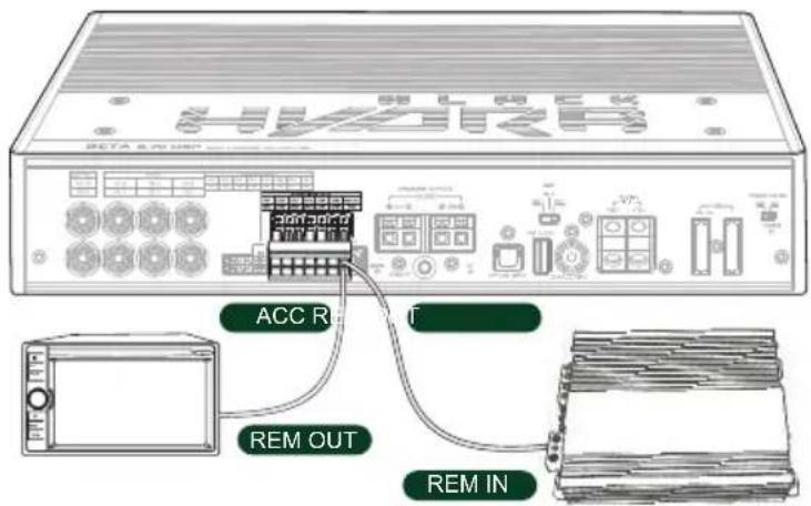
You can also use remote output terminal REM OUT to automatically turn on second amplifier in your audio system.
BLUETOOTH CONNECTION
Amplifier has built in Bluetooth 5.0, module which supports AptXHD high quality sound profile.
To connect your device to amplifier's Bluetooth module navigate to your device Bluetooth settings and search for Bluetooth device named BETA8. 70 DSP then pair your device with amplifier's Bluetooth. After successful pairing BT LED at the amplifier's side panel will light up blue.

USB-AUDIO CONNECTION FOR ANDROID OS AND WINDOWS PC DEVICES
This amplifier supports digital USB-Audio connection to Android OS and Windows PC devices. To connect your amplifier to your device, plug in USB Type-A (2.0/3.0) cable to the USB Type-A port at the amplifier's side panel then connect it to your device. You will see device named BH DSP AMP in output devices list. Select this device as a default sound output device.

NOTE: THIS AMPLIFIER DOES NOT SUPPORT PLAYBACK FROM EXTERNAL USB FLASH DRIVES AND HDD/SSD DRIVES.
DIGITAL OPTICAL OR ELECTRICAL S-PDIF INPUT SIGNAL CONNECTION
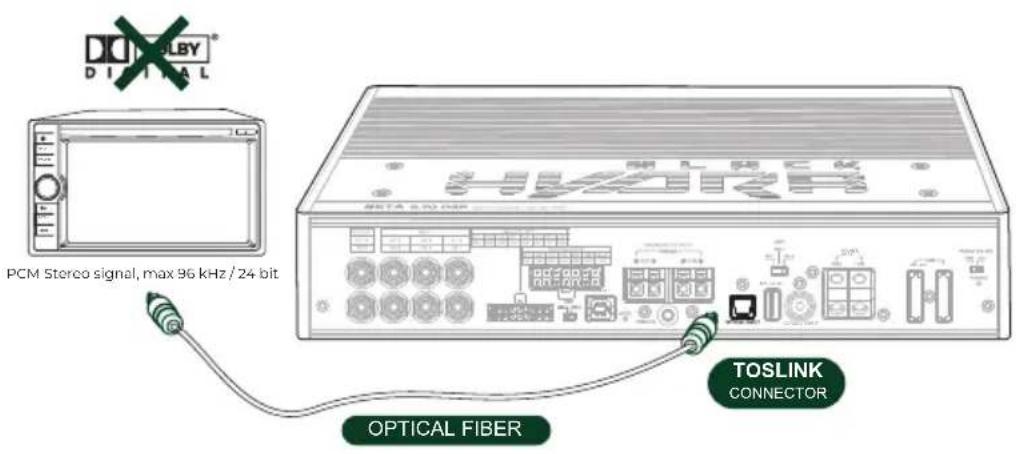
This amplifier accepts at its input PCM signals up to 96 kHz/24 bit. Sampling frequency rate. So DOLBY DIGITAL (AC3) multi-channel signals coming from audio/video sources (such as the audio of a DVD video) or DTS cannot be reproduced.
Connect a fiber optic cable with a TOSLINK connector to (OPTICAL INPUT) or coaxial cable to a coaxial connector(COAXIAL INPUT).
OPTICAL S-PDIF CONNECTION
COAXIAL CONNECTION

NOTE: THE OUTPUT OF THE CONNECTED DEVICE NEED TO BE SET IN STEREO MODE FOR THE SIGNAL TO BE REPRODUCED.
How to select the OPTICAL or COAXIAL input:
- Using the DRC (sold separately), selecting the OPTICAL or COAXIAL input.
- Using the Windows PC software.
HIGH-LEVEL SIGNAL INPUT CONNECTION
This amplifier is provided with a 16-pin high-level input connector to which up to a maximum of 8 high-level input channels can be connected. This port allows using the amplifier automatic turn on function, it's also accepts signals coming from an amplified source with a voltage level between 6.5 V and 15 V RMS.

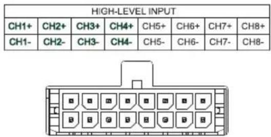
The channels CH1, CH2, CH3, Ch4 feature the auto turn on function for automatic turn on/off of the amplifier in case of connection of high-level input signals. This function can be enabled or disabled via the POWER ON SW switch on the amplifier's side panel.
Example1. High-level input: 2-way front + rear.
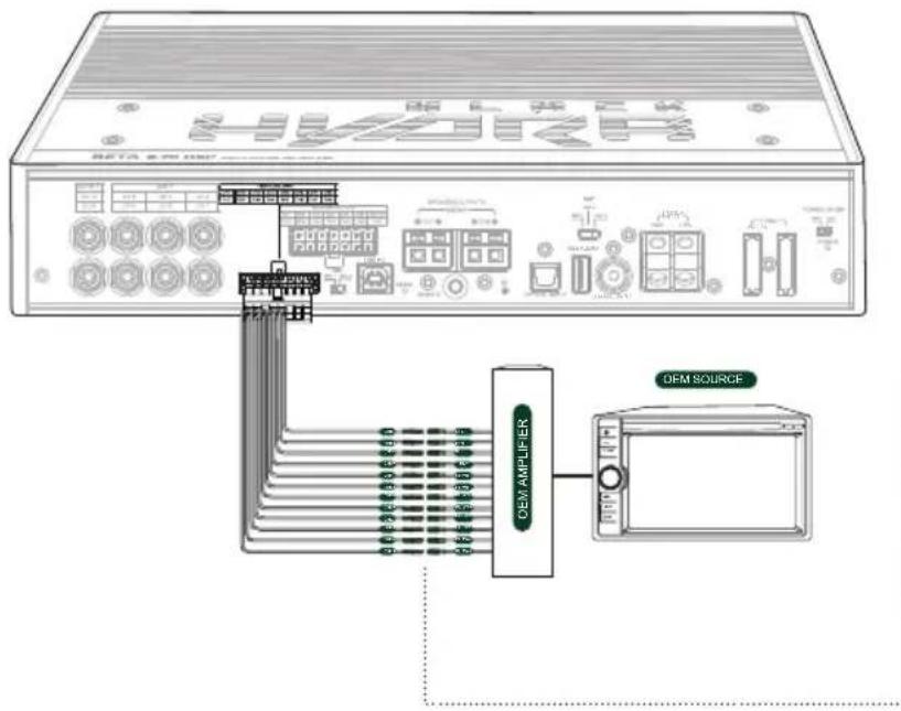

Example 2. High-level input: 2-way front + rear + center + sub.

LOW-LEVEL SIGNAL INPUT CONNECTION
This amplifier has 6 low-level RCA inputs. This inputs accept signals from a pre-amplified source, the signal to be applied must have a level between 0.78 V and 6 V RMS. These input channels can be customized in different ways through the use of the Windows PC Software.
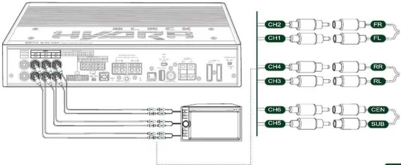
CONNECTION OF ADDITIONAL AMPLIFIER
The amplifier has two RCA outputs that can be used to connect second amplifier if you want to use up to 16 amplified channels in your sound system.

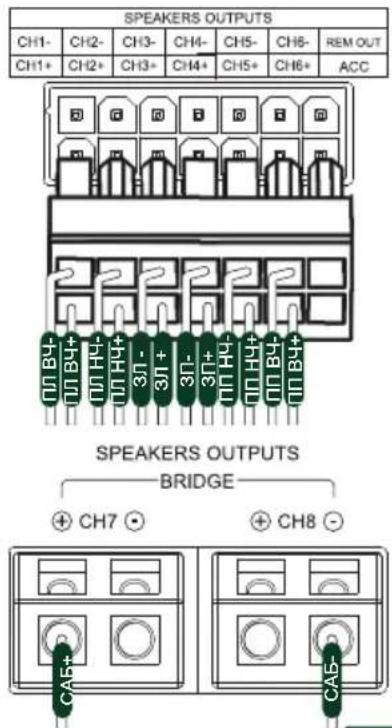
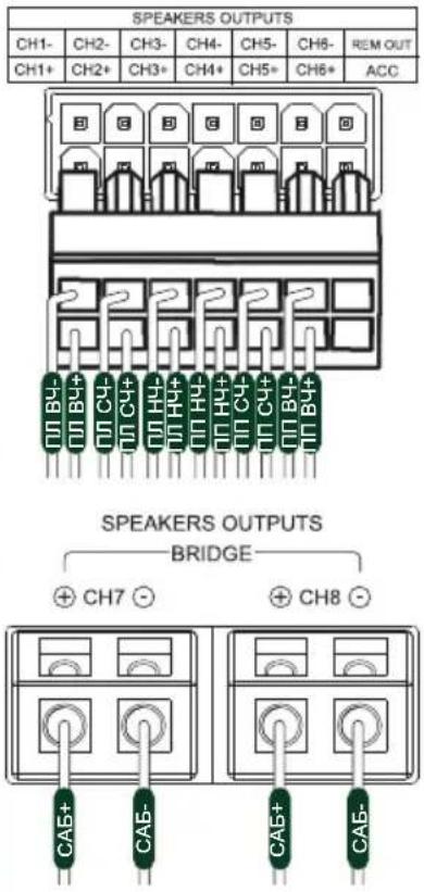
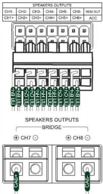
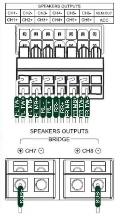
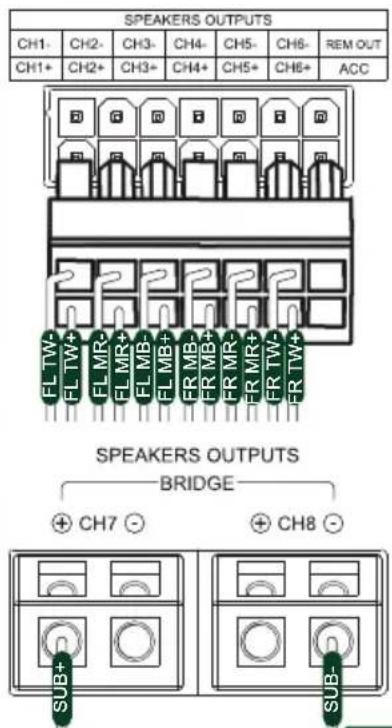
SPEAKERS OUTPUTS
The amplifier is supplied with a 14-pin multifunctional connector to which up to 6 output amplifier's AB class channels can be connected with RMS power of 70W @ 4Ohm for each channel.

Additionally, amplifier has two D class output channels which can be used in bridged mode with output RMS power of 220W @ 4Ohm or 2x110W @ 2Ohm in per channel connection.
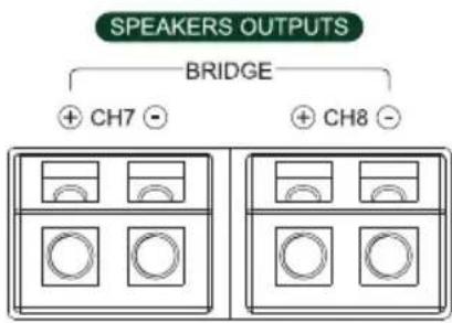
The output channels can be configured by Windows PC software. Each channel features:
Parametric EQ with 31 poles; -
- Crossover with arbitrary frequency steps in the range from 20 to 20 000 Hz and selectable frequency response filter type (Butterworth, Bessel or Linkwitz-Riley) with slope in the range from 6 to 48 dB/Oct;
- Digital time delay correction 0-20mc/0-679.38cm/0-269.57inch;
- Phase inversion 0,180°;
- Channel level control in the range from +6 to -60dB;
Example 1. Speakers outputs: 2-way front + 2-way rear + subwoofer in bridged mode

flowchart
graph TD
    A["Device 1"] --> B["Switch"]
    C["Switch"] --> B
    D["Speaker 1"] --> B
    E["Speaker 2"] --> B
    F["Speaker 3"] --> B
    G["Speaker 4"] --> B
    H["Speaker 5"] --> B
    I["Speaker 6"] --> B
    J["Speaker 7"] --> B
    K["Speaker 8"] --> B
    L["Speaker 9"] --> B
    M["Speaker 10"] --> B
    N["Speaker 11"] --> B
    O["Speaker 12"] --> B
    P["Speaker 13"] --> B
    Q["Speaker 14"] --> B
    R["Speaker 15"] --> B
    S["Speaker 16"] --> B
    T["Speaker 17"] --> B
    U["Speaker 18"] --> B
    V["Speaker 19"] --> B
    W["Speaker 20"] --> B
    X["Speaker 21"] --> B
    Y["Speaker 22"] --> B
    Z["Speaker 23"] --> B
    AA["Speaker 24"] --> B
    AB["Speaker 25"] --> B
    AC["Speaker 26"] --> B
    AD["Speaker 27"] --> B
    AE["Speaker 28"] --> B
    AF["Speaker 29"] --> B
    AG["Speaker 30"] --> B
    AH["Speaker 31"] --> B
    AI["Speaker 32"] --> B
    AJ["Speaker 33"] --> B
    AK["Speaker 34"] --> B
    AL["Speaker 35"] --> B
    AM["Speaker 36"] --> B
    AN["Speaker 37"] --> B
    AO["Speaker 38"] --> B
    AP["Speaker 39"] --> B
    AQ["Speaker 40"] --> B
    AR["Speaker 41"] --> B
    AS["Speaker 42"] --> B
    AT["Speaker 43"] --> B
    AU["Speaker 44"] --> B
    AV["Speaker 45"] --> B
    AW["Speaker 46"] --> B
    AX["Speaker 47"] --> B
    AY["Speaker 48"] --> B
    AZ["Speaker 49"] --> B
    BA["Speaker 50"] --> B
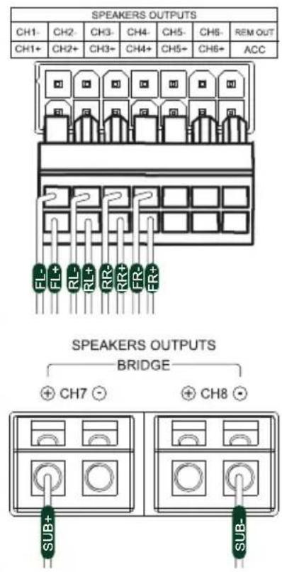
Example 2. Speakers outputs: 2-way front + broadband rear + subwoofer in bridged mode

Example 3. Speakers outputs: 3-way front + two subwoofers.


Example 4. Speakers outputs: 3-way front + subwoofer in bridged mode.

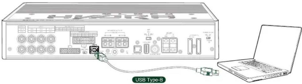
Use USB Type-B connection cable to connect the amplifier to a Windows PC in order to manage all of its functions using Windows PC software. PC connection port is USB 2.0/3.0 compatible.
Scan this QR code to download PC software

Attention!!! You need to download the application for Windows PC to control all amplifier settings.
WINDOWS PC SOFTWARE OVERVIEW
The application is compatible with all versions of Windows10 and Windows11, for user convenience, the application does not require installation, you need only to unzip the executable file of the application to any folder of your choice, then launch the application by double-clicking on its icon in Windows explorer.
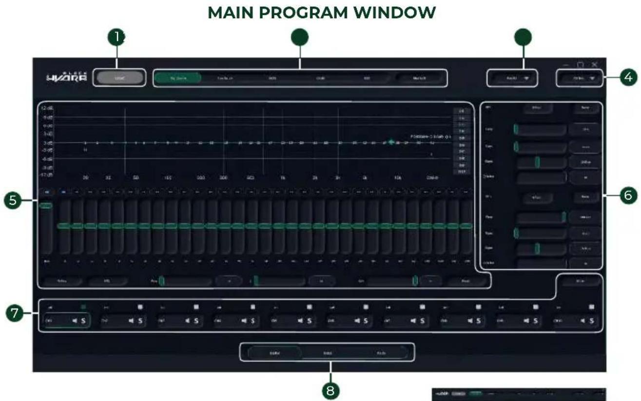
1 Connection to the amplifier
② Signal source selection
3 Load/Save of amplifier settings
4 Basic software setup
5 Equalizer setup
6 Filtering setup
7 Output channel grouping
8 Switching between setup modes
9 Digital time delay correction settings setup mode
10 Signal routing setup

CONNECTION TO THE AMPLIFIER
After launching the application, you will see the main screen, in the upper left corner of the screen, there is a button for pairing with the amplifier, the gray color of the button means that the amplifier is disconnected, green color means a successful connection. Click on the button to connect to the amplifier.
SIGNAL SOURCE SELECTION
To select a signal source, use the buttons at the top of the main screen.

Active signal source will be highlighted in green.
LOAD/SAVE OF AMPLIFIER SETTINGS
To save your amplifier settings for later use, click the button in the upper right corner of the screen.
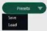

In the pop-up menu, click Save and select the memory cell number where you want to save the amplifier settings.
2 You can also export the settings to a file to save it on your PC. To do this, click the export button, enter the file name and select the save location in Windows explorer, then confirm your choice by clicking the save button.
BASIC SOFTWARE SETUP
For basic software setup, click on the Options▼ in the upper right corner of the main application screen.
In this menu you can select the system language, view the software version, the amplifier firmware version, and also return to the factory default settings of the application. To perform the selected action, click on the corresponding menu item.
EQUALIZER SETUP
The amplifier has the ability to configure a 31-band parametric equalizer with an arbitrary frequency steps for every single output channel.

To set up the equalizer, select the output channel for which the equalizer will be set up by clicking on the corresponding channel selection button.
You can also set up the equalizer for several channels by combining them into groups. To group,

mark the channels you need by clicking on the checkbox next to the channel name.
IMPORTANT! WHEN GROUPING CHANNELS, ALL SETTINGS (FILTER AND EQUALIZER SETTINGS) FOR THE SELECTED CHANNELS ARE MERGED.
Next, select the frequency, level, and Q-factor for the selected equalizer frequency. All equalizer settings are applied in real time.

There are several ways to setup the required equalizer settings, all of them are marked in the picture above, use the most convenient setup method for you.
The equalizer supports switching to a fixed (parametric) mode in which all 31 equalizer adjustment frequencies are fixed and pre-selected by the manufacturer. To turn on the fixed equalizer mode, press the PEQ button 1.
To temporarily disable the equalizer without resetting its settings, press the EqPass button 2.
To reset the equalizer settings, press the RESET button 3, then in the dialog menu select the desired reset option, all equalizer settings for all cannels or settings for only current channel, you can also cancel the reset process by pressing the cancel button.
FILTERING SETUP
The amplifier has the ability to apply per channel filtering with an arbitrary frequency steps in the range from 20 to 20 000 Hz and slope from 6 to 48 dB/Oct for each of the 10 output channels.

To set up filtering, select the output channel for which the filters will be set up by clicking on the corresponding channel selection button. You can also set up filters for several channels by combining them into groups. To group, mark the channels you need by clicking on the checkbox next to the channel name.
IMPORTANT! WHEN GROUPING CHANNELS, ALL SETTINGS (FILTER AND EQUALIZER SETTINGS) FOR THE SELECTED CHANNELS ARE MERGED.
Next, select the frequency, type of the frequency response filter, slope and Q-factor for the selected operating frequency of HPF and LPF filters.
All crossover settings are applied in real time and are displayed on the frequency response graph.

There are several ways to setup the required filter settings, all of them are marked in the picture above, use the most convenient setup method for you.
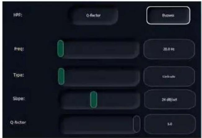

To temporarily disable the selected filter without resetting its settings, click the BYPASS button next to the filter name
OUTPUT CHANNEL GROUPING FOR EASE OF SETUP

To group, mark the output channels you need by clicking on the checkbox next to the channel
name. It is also possible to temporarily mute the current channel or all other channels except the current one by clicking on the corresponding icons next to the channel name.
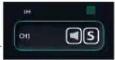
IMPORTANT! WHEN GROUPING CHANNELS, ALL SETTINGS (FILTER AND EQUALIZER SETTINGS) FOR THE SELECTED CHANNELS ARE MERGED.
For ease of setup when using output channels in stereo mode, they can be automatically paired by pressing the LR Link button
SWITCHING BETWEEN SETUP MODES
To select the setup mode, use the buttons at the bottom of the main application screen; they allow you to switch from equalizer and filtering settings to time delays settings and signal routing settings.

DIGITAL TIME DELAY CORRECTION SETTINGS SETUP MODE
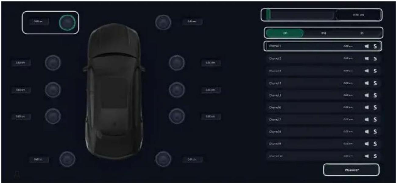
If you need to reverse the signal phase from 0^ to 180^ on the selected channel, use the PHASE button.
To set up time delays, select the desired output channel and required measurement units in which time delay values will be entered, then enter desired time delay value.
It is also possible to temporarily mute the current channel or all other channels except the current one by clicking on the corresponding icons next to the channel name Channel 1 0.00 cm
There are several ways to enter the required values for the time delay settings, all of them are marked in the picture above, use the most convenient setup method for you.
The amplifier supports time delay adjustment in the following unit ranges: 0-20ms/0-679.38cm/0-269.57inch.
SIGNAL ROUTING SETUP
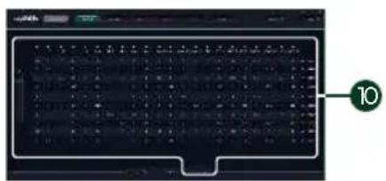
If there is a signal divided into separate channels at the amplifier input, it can be combined or transmitted without conversion to the desired amplifier channel using the routing table. The routing table supports signal level adjustment for each channel in the range from 0 to 100%.

To configure signal routing, use the routing table, where all possible signal inputs are located horizontally, and all possible signal outputs are located vertically.
To select the signal level from the input you need to the output you have selected, find its value in the table and click on the corresponding value, then adjust the signal level using the slider located to the left of the routing table or enter the desired value directly from PC keyboard.
| SPECIFICATIONS BETA 8.70 | DSP |
| Class | AB+D |
| Number of Channels | 8 |
| Power RMS, 4 Ohm | 6 x 70 W + 2 x 90 W |
| Power RMS, 2 Ohm | 6 x 80 W + 2 x 110 W |
| Power RMS, 4 Ohm (bridged mode) | 1 x 220 W |
| Inputs | 6 x RCA |
| 8 x HIGH-LEVEL | |
| 1 x OPTICAL | |
| 1 x COAXIAL | |
| 1 x ACC | |
| 1 x USB AUDIO | |
| 1 x USB PC | |
| Outputs | 8 x SPEAKER OUTPUT |
| 2 x RCA | |
| 1 x REM OUT | |
| Frequency response | 20 - 20 000 Hz |
| THD | AB - <0.015 (1 kHz) / D - <0.05 (1 kHz) |
| Signal to noise ratio | ≥100 dB |
| Input impedance | 10 kOhm |
| Input sensitivity (Low level inputs) | 0,78 - 6 V |
| Input sensitivity (High level inputs) | 6,5 - 15 V |
| Crossover | LPF: 20 - 20 000 Hz at 6 - 48 dB/OctHPF: 20 - 20 000 Hz at 6 - 48 dB/Oct |
| Fuses | 2 x 35 A |
| Audio DSP | ADAU1452 |
| DAC | 24 bit 96 kHz |
| ADC | 24 bit 96 kHz |
| Working voltage | 10-17 V |
| Size (LxWxH), mm / inch | 312 x 180 x 55 / 12.28 x 7.1 x 2.17 |
WARRANTY PERIOD, AFTER-SALES SERVICE AND SERVICE LIFE INFORMATION
Each BLACK HYDRA product is warranted to be free from defects in materials and workmanship under normal use and service.
The warranty period for the product is 12 (twelve) months from the date on which the product is transferred to the consumer (this date shall be deemed to be the date on which the consumer starts using the product).
During the warranty period, defective parts will be repaired or replaced at the discretion of the manufacturer provided that there are grounds for doing so under the laws of the consumer's country. The defective product must be returned to the dealer from whom it was purchased together with the duly filled out warranty certificate, complete, with original packaging.
Our company shall not be liable for any damage caused by transportation. Our company shall not be liable for any expenses or lost profits arising out of or in connection with the use or inability to use the product or any other incidental or indirect costs, expenses, or damages incurred by the customer. The warranty is valid in accordance with the laws currently in force. For more information, please visit our company website and refer to the warranty card.
The manufacturer reserves the right to change the design and specification of the product without prior notice.
The service life of the product is 12 (twelve) months from the date on which the product is transferred to the consumer (this date shall be deemed to be the date on which the consumer starts using the product).
The product or any part (component) of the product must not be used in any way (including, but not limited to use for intended or any other purpose, transportation, storage, modification/alteration/improvement/upgrade) after the expiry of the service life.
At the end of its service life, the product must be disposed of.
INFORMATION ON DISPOSAL OF THE ELECTRICAL AND ELECTRONIC EQUIPMENT (FOR THE EUROPEAN COUNTRIES WITH SEPARATE WASTE COLLECTION)
Items marked “crisscrossed wheeled bin” are not allowed to be disposed of together with usual household waste. These electrical and electronic products should be disposed of in special reception centers, equipped for recycling such products and components. For information about the location of the nearest disposal / recycling spot and the rules of delivery of waste, please contact your local municipal office. Recycling and proper disposal helps to protect the environment and prevent harmful effects on health.
Manufacturer: Ningbo Basshead I&E Trading Co., Ltd Made in China


https://alphard.audio

- BLUETOOTH CONNECTION
- USB-AUDIO CONNECTION FOR ANDROID OS AND WINDOWS PC DEVICES
- DIGITAL OPTICAL OR ELECTRICAL S-PDIF INPUT SIGNAL CONNECTION
- HIGH-LEVEL SIGNAL INPUT CONNECTION
- LOW-LEVEL SIGNAL INPUT CONNECTION
- CONNECTION OF ADDITIONAL AMPLIFIER
- SPEAKERS OUTPUTS
- WINDOWS PC SOFTWARE OVERVIEW
- CONNECTION TO THE AMPLIFIER
- SIGNAL SOURCE SELECTION
- LOAD/SAVE OF AMPLIFIER SETTINGS
- BASIC SOFTWARE SETUP
- EQUALIZER SETUP
- IMPORTANT! WHEN GROUPING CHANNELS, ALL SETTINGS (FILTER AND EQUALIZER SETTINGS) FOR THE SELECTED CHANNELS ARE MERGED.
- FILTERING SETUP
- OUTPUT CHANNEL GROUPING FOR EASE OF SETUP
- SWITCHING BETWEEN SETUP MODES
- DIGITAL TIME DELAY CORRECTION SETTINGS SETUP MODE
- SIGNAL ROUTING SETUP
- WARRANTY PERIOD, AFTER-SALES SERVICE AND SERVICE LIFE INFORMATION
- INFORMATION ON DISPOSAL OF THE ELECTRICAL AND ELECTRONIC EQUIPMENT (FOR THE EUROPEAN COUNTRIES WITH SEPARATE WASTE COLLECTION)
Brand : Black Hydra
Model : Beta 8.70 DSP
Category : Receiver