Xander - PC Case Azza - Free user manual and instructions
Find the device manual for free Xander Azza in PDF.


| Product Type | PC Case (Mid-Tower) |
| Brand | Azza |
| Model | Xander |
| Form Factor | ATX, Micro-ATX, Mini-ITX |
| Dimensions (L x W x H) | 450 x 210 x 480 mm (approx.) |
| Weight | 6.5 kg (approx.) |
| Material | Steel, Tempered Glass |
| Motherboard Support | ATX, Micro-ATX, Mini-ITX |
| Expansion Slots | 7 |
| Drive Bays | 2x 3.5", 2x 2.5" |
| Fan Support | Front: 3x 120mm or 2x 140mm, Top: 2x 120mm, Rear: 1x 120mm |
| Radiator Support | Front: up to 360mm, Top: up to 240mm, Rear: 120mm |
| PSU Support | Bottom mount, ATX PSU |
| Front Panel Ports | USB 3.0, USB 2.0, Audio/Mic |
| Window | Tempered Glass Side Panel |
| Dust Filters | Front, Top, Bottom |
| Max CPU Cooler Height | 165 mm |
| Max GPU Length | 350 mm |
| Max PSU Length | 200 mm |
| Warranty | 2 years (typical) |
| Included Accessories | Screws, Standoffs, Cable ties |
Frequently Asked Questions - Xander Azza
User questions about Xander Azza
0 question about this device. Answer the ones you know or ask your own.
Ask a new question about this device
Download the instructions for your PC Case in PDF format for free! Find your manual Xander - Azza and take your electronic device back in hand. On this page are published all the documents necessary for the use of your device. Xander by Azza.
USER MANUAL Xander Azza
natural_image
Technical line drawing of a computer tower case with fan and ventilation slots (no text or symbols)Xander
COMPUTER CASE
USER MANUAL
- Specifications
- Chassis Parts
- Control Panel Functions
- 3.5"/2.5" HDD/SSD Installation
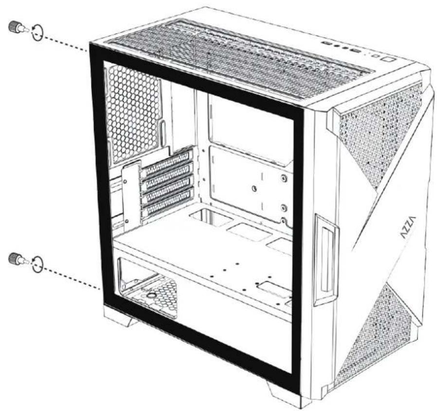
- Remove the left glass side panel
- Remove the right metal side panel
- Remove the Front panel
- From top to bottom, fasten the panel to chassis
- Cooling System Installation
- Master Fan & Sub-fan Installation
- Fan Installation
- RGB Lighting Switching
| Model | |
| Model Name: | Xander |
| Model Number: CSAZ-150 | |
| Specifications | |
| Type: Micro ATX Mid Tower | |
| Color: Black/Black(interior) | |
| Side Panel Window: Left side panel: slidable | tempered glass panel |
| Max CPU Cooler Height: UP to 175mm | |
| Max Video Card Length: Up to 340mm long | video card |
| Power Supply: Not included | |
| Motherboard Compatibility: | Micro ATX、ITX |
| Expansion | |
| External 5.25" Drive Bays: 0 | |
| Internal 2.5" Drive Bays: Up to 4 | |
| Internal 3.5" Drive Bays: Up | to 2 |
| Expansion Slots: 4 | |
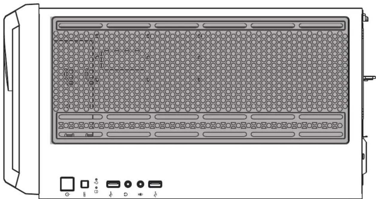
| Top Ports: | Power button, LED button, HD Audio, USB 3.0 x 2 |
| Physical Specifications | 410x220x381 / 16.1x8.7x15 inches |
| Weight: | 5.6kg /12.3lbs |
| Features | |
| Tempered Glass Sides Window: | High-quality tempered glass side window allows for clear visuals to inner components |
| Addressable RGB Light Effects: | All ARGB light sync. devices connected to the ARGB control board, allowing the LED button or switch to the motherboard software to directly control the ARGB lighting. |
| Available Fan Ports: | 3x120mm or 2x140mm Fan ports in the front(2x120mm LFO-4412D ARGB fan included)3x120mm or 2x140mm Fan ports on the top1x120mm Fan port in the rear(1x120mm LFO-4412D ARGB fan included) |
| Water Cooling: | Supports radiators up to 240/280mm on the topSupports radiators up to 240/280mm in the front |
| Dust Filters: | Removable (magnetic) dustproof net on the top and front, dust filter on bottom of chassis. |
| Power Supply Support: | Bottom mounted ATX Power Supply |
※PWM Fan:The model comes with PWM fans and will run at top speed unless connected to a motherboard or controller.
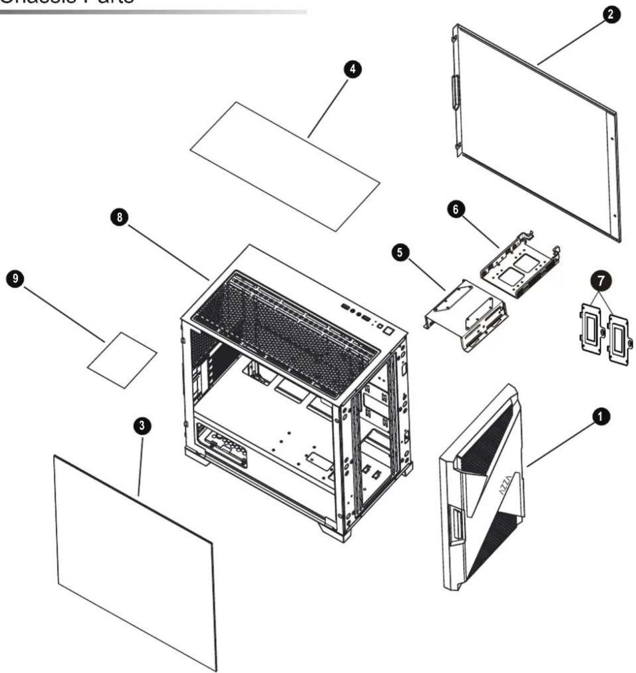
| 1 | Front panel |
| 2 | Metal side panel |
| 3 | Tempered glass panel |
| 4 | Removable magnetic mesh |
| 5 | Hard disk cage |
| 6 | 3.5" HDD/ 2.5" SSD brackets |
| 7 | 2.5" SSD tray x 2 |
| 8 | Chassis |
| 9 | Dust filter mesh |

natural_image
Front view line drawing of a device casing with control panel and indicator lights (no text or symbols)| POWER | |
| LED | |
| Mic | |
| Audio |
| USB 3.0 | |
| USB 3.0 |

- Supports up to 390mm long video cards.
or


natural_image
Technical line drawing of a computer chassis showing internal components and mounting points (no text or labels)- Multifunctional hard disk bracket support 3.5" HDD or 2.5" SSD x 1 ( A )
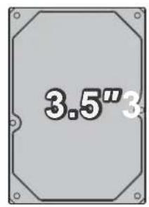
-2.5" SSD metal tray support 2.5" SSD x 2 ( © ) - Multifunctional hard disk cage support 3.5" HDD or 2.5" SSD x 1( B )
natural_image
Technical line drawing of a desktop computer case with visible internal components and ventilation slots (no text or labels)
natural_image
Technical line drawing of a computer tower case with visible internal components and directional arrows indicating movement (no text or symbols)
natural_image
Technical line drawing of a server unit with ventilation grilles and cooling fins (no text or symbols)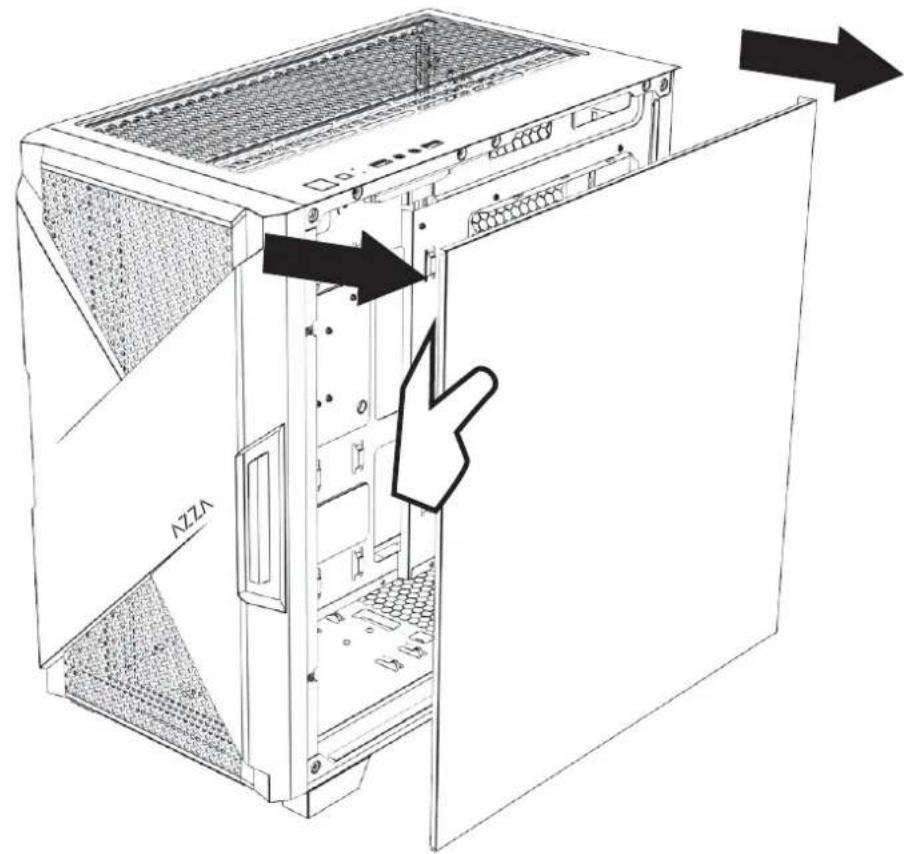


natural_image
Technical line drawing of a computer tower case with visible internal components and a black arrow indicating a specific part (no text or symbols present)
natural_image
Technical line drawing of a computer tower case with internal components and ventilation ducts (no text or symbols)
natural_image
Technical line drawing of a server rack cabinet with hexagonal mesh panel and ventilation grilles (no text or symbols)Front


natural_image
Line drawing of a fan with six blades, enclosed in a square frame (no text or symbols)120mm x3
or

natural_image
Line drawing of a fan with six blades, no text or symbols present140mm x2
Rear
natural_image
Technical line drawing of a server rack with hexagonal mesh panel and internal components (no text or symbols)
natural_image
Line drawing of a fan with six blades, no text or symbols present120mm x1
Top

natural_image
Line drawing of a fan with six blades, no text or symbols present120mm x3
or

natural_image
Line drawing of a fan with six blades, enclosed in a square frame (no text or symbols)140mm x2
natural_image
Front view of a computer RAM unit with hexagonal grid layout and indicator lights (no text or symbols)
natural_image
Gray left-pointing arrow on white background (no text or symbols)Max Length of Radiator
280mm

natural_image
Gray right-pointing arrow icon on white background (no text or symbols)
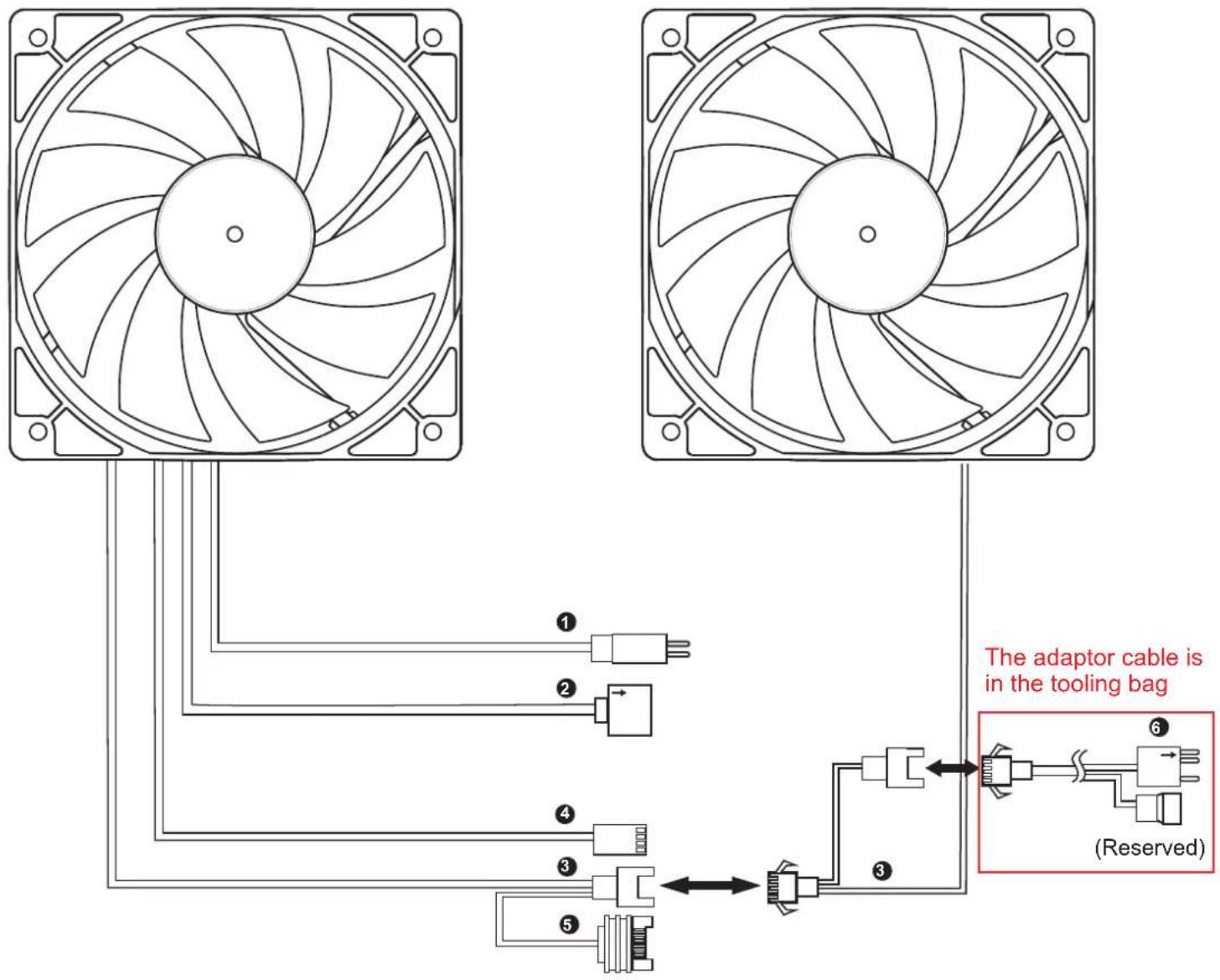
| CONNECTOR CONNECTION | CONNECTION | |
| 1 | Reset (LED) S/W (2pin) | LED Button |
| 2 | ARGB LED 5V (3pin) female connector | The 5V/3pin ARGB socket of the motherboard |
| 3 | Fan Connector | The master Fan connect to the sub-fan |
| 4 | Fan Connector PWM (4pin) | CHA_FANx socket of the motherboard |
| 5 | SATA Power Supply | |
| 6 | ARGB LED 5V (3pin) male connector | Other 5V/3pin ARGB devices |
※ Before the fan starts, please make sure the PWM connector ④ and SATA connector ⑤ each are connected.
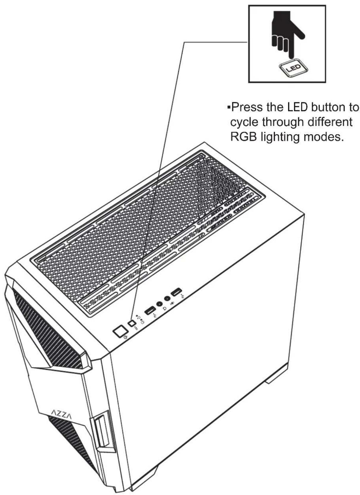
※Press the LED button to cycle through different RGB lighting modes, all ARGB devices are controlled by the LED button. (make sure the other 3pin ARGB devices are connected with ⑥)
※Ensure ② insert the motherboard, and hold the LED button for 3 seconds to switch the RGB control function to the motherboard RGB sync. software. Press 1 second LED button, and switch the RGB control function to the LED button.