P-700u - Headphone amplifier LUXMAN - Free user manual and instructions
Find the device manual for free P-700u LUXMAN in PDF.

User questions about P-700u LUXMAN
0 question about this device. Answer the ones you know or ask your own.
Ask a new question about this device
Download the instructions for your Headphone amplifier in PDF format for free! Find your manual P-700u - LUXMAN and take your electronic device back in hand. On this page are published all the documents necessary for the use of your device. P-700u by LUXMAN.
USER MANUAL P-700u LUXMAN
Contents
Precautions ...... 1
Product Characteristic ....2
Names and Functions 4
Memory 6
Connections 7
Before Making Connections 8
Block Diagram 9
Specifications 10
Troubleshooting 11
Precautions
Installation place
This unit should be installed in a well-ventilated place to allow for easing air circulation. Do not install this unit at a place where it would come under direct sunlight or where the high temperatures are expected like close to a heater. Keep the unit away from places where humidity level is high or excessive dust is present, this may cause malfunction of the unit.
Cautions in connecting input components
When connecting this product to a source like a CD player, be sure to turn off this device and the connecting source. Failure to observe this may generate a pop noise resulting in headphone damage or temporary malfunction.
Make sure to insert the plug-pin firmly in the each input terminal of this product, failure to do so will give rise to inadequate grounding resulting in distorted output signals with a high signal to noise ratio.
Protection circuit
This product is equipped with a protection circuit that guards against over-current, abnormally high temperatures and DC drift. When the protection circuit is activated, the output to the headphone is terminated and the operation light blinks to indicate the status of the product to be in mute mode. If the protec on circuit is frequently ac vated a er a lapse of a certain time and turning on the power again, please consult your dealer.
Sound is not generated immediately after the power supply is turned on.
This amplifier is equipped with a mute circuit which is activated for a short period of time at switch on. Therefore, no sound is generated shortly after the power supply is turned on. Please be patient and do not increase the volume during this period as this will suddenly generate a highly amplified sound. It is advised that the volume control be set to a low level at first and adjusted once you hear the sound from you headphones.
Repair and adjustment
There are no user servable parts inside the unit, please do not attempt to open it yourself, doing so will void your warranty. When repairs or adjustments are needed, please consult your dealer or the authorized local distributor.
Cleaning
The amplifier should only ever be cleaned with a soft dry cloth to remove finger marks, etc... Do not use a solvent like benzene or thinner because such a substance can often damage the exterior.
Pay attention to use the headphone
For a long time continuous use ear stimulating the volume, may cause damage to hearing.
3 Darlington output section
Made up of Bipolar Transistor's 3 section Darlington.
Balance: 8 w + 8w (16Ω) and Unbalance: 4w + 4w (8Ω) rated output.
Can be corresponding to the Balance of the headphone is high quality Balance/unbalance headphone
It has the same independent quality of 4 channel discrete 'amplifier, corresponding XLR can balance headphone.
Transfer the balance input and output can be straight, unbalance is L/R2 straight transmission on the channel in parallel connection, the composition has a strong driving force.
It can also be corresponding to the balance of input and unbalance, headphone, unbalance input to the balance of the headphone.
LECUA – LUXMAN Electric Controlled Ultimate Attenuator
Mount with Electrically controlled attenuator for gaining attenuation amount in combination with the resistance.
By using the dedicated solid state IC to control the attenuator to the sound volume corresponding to the angle of the volume knob, the operation texture similar with conventional slide-type volume is realized.
And balance phase of the power amplifier, correlation of inverse phase error function also is very good, can accurately control the balance.
ODNF – Only Distortion Negative Feedback–
The amplification feedback circuit that has acquired the high-speed primary slew rate and ultra-high bandwidth by feeding back only distortion components generated during amplification to maintain the pure sound quality of the main-amplifier that is almost non-feedback.
The newest version, 3.0A, has achieved the low impedance and high S/N ratio of the transmission circuit by parallelization of the first and second stages of the error detection circuit are parallelized to moderate the frequency characteristic and noise.
High inertia power source
High-inertia electronic circuit that combines a large-capacity Ol-core-type power transformer with customizable 10,000 F × 2 capacitor blocks.
Parallel speaker relay
Will be used 2 the company merger borne power amplifier, low impedance value of large Speaker relay in parallel, reduces the headphone output impedance of the line.
B-line construction
Newly designed beeline construction composes the audio input signal via the optimally shortest route to the output.
Selector relay
Adopted power amplifier used by the company can improve the high quality of separation and crosstalk performance Selector relay.
Schottky barrier diode
Application of schottky barrier diode manufactured by Nihon Inter Electronics Corporation that has less switching noises and higher conversion efficiency to the DC voltage for the power supply rectifier circuit.
Original OFC wire
Our original OFC wires are used in the internal wiring to achieve smooth signal transmission thanks to the spiral wrap shielding on each core and the non-plating process on the core wire.
Round pattern circuit board
After careful consideration of delicate audio signal flow, around pattern board has been applied to achieve smooth signal transmission.
Sensitivity switch
This machine is equipped with can match the headphone power used in HIGH/MID/LOW sensitivity selector switch.
Through output switch
The LINE of the input signal can through the output of the output terminal to set on/off.
Roofless chassis structure
This unit consists of the independent construction of a loopless chassis to eliminate increased ground impedance caused by chassis current.
18mm pitch RCA terminal
Introduction of 18mm pitch all RCA input/output terminals allows even a high-performance line cable with large plug to be connected.
Balance type headphone terminals
Non-locking type's high quality XLR terminals have both of reliability and safety.
Unbalance type headphone terminals
Using two high quality headphone terminal.
New standard size
Using the design is 440mm wide, new size panel height is 80mm high rigid frame (chassis).
AC inlet
This inlet enables the connection with an external power cable.
※ About balance type headphone, headphone amplifier
- The balance type of headphone is to point to by positive phase (HOT) and reverse phase (COLD) drive headphone driver unit, configurable L/R earth (COLD) isolated four core type of headphone. Generally USDS is XLR3pin type of balance connector.
- Balance headphone amplifier has the 4 channel amplifier, HOT and COLD in each L ch and R ch, XLR's balance headphone terminal signal configuration has shown in below.
(1) GROUND
(2) HOT (positive phase)
(3) COLD (inverse phase)
Front panel
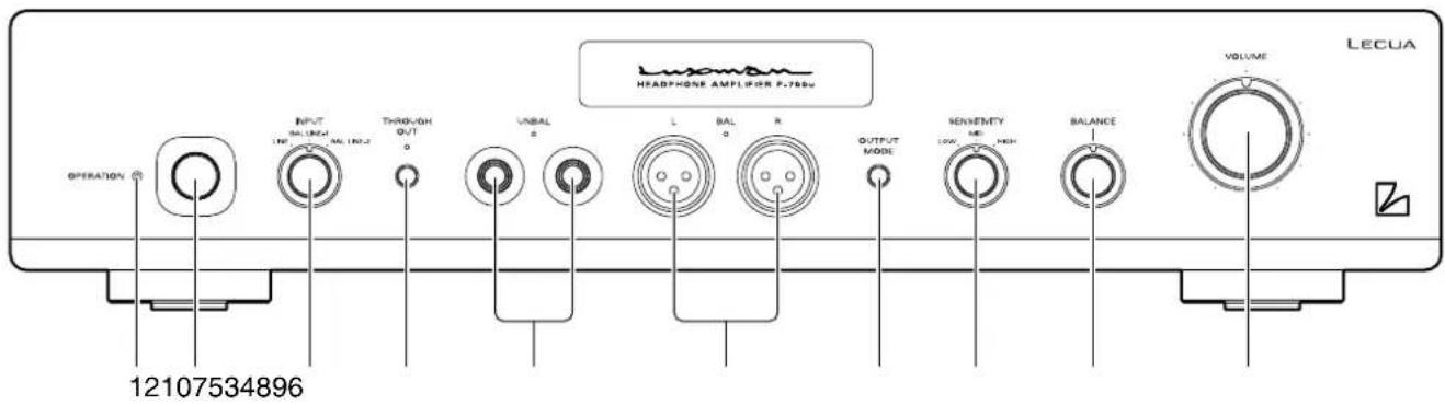
1. Operation indicator
Blinks in the time muting mode when the power switch is turned on and lights up when the operation state is activated.
2. Power switch (OPERATION)
Toggle the power on and off.
When wiring or connection is performed, be sure to turn off this switch.
3. Input selector (INPUT)
Selector switch for line or balance input.
4. Through out switch (THROUGH OUT)
Through out on/off switch.
Line input signal pass through to line out in the rear panel, for connected to other amplifier or sources.
5. Headphone jack (UNBAL)
Insert the use headphone plug-in. Two jack can output the same music signal, please use the impedance for more than 8 Ω headphone jack. If use two jack at the same time, please use the impedance for more than 16 Ω headphone.
6. Balance headphone terminals (BAL L/R)
Insert the balance used type of headphone XLR connectors. Please use the impedance for more than 16 Ω headphone.
This machine is the balance of the output terminal can output the following signals.
① GROUND
② HOT
③ COLD
7. Headphone output switch (OUTPUT MODE)
It can choose a headphone output terminal's of the unbalance (UNBAL) and the balance (BAL) output terminal of the output switch. Each button can switch the headphone output of unbalance and balance.
Select the unbalance (UNBAL) or the balance (BAL), ingicator will bright lights.
8. Sensitivity switch (SENSITIVITY)
The headphone according to use the power switch can be HIGH, MID and LOW.
Headphone power is low, if large volume control volume is still insufficient, can be set to HIGH.
On the other hand, if the headphone power is high, the volume control is not easy to control, is set to LOW.
The sensitivity of the machine set for the following.
HIGH: 0dB
MID: -6dB
LOW: -12dB
9. Balance control (BALANCE)
Adjust the balance of sound between right and left channels. Rotating this switch counter clockwise causes the left sound volume to be enhanced, and rotating the switch clockwise causes the right sound volume to be enhanced. This switch shall be set to the centre position under normal conditions and rotated to make adjustment if necessary.
10. Volume control (VOLUME)
Adjust the sound volume. Sound is not generated when this control is rotated counter clockwise to the end, and then, the sound volume gradually becomes higher when the control is slowly rotated clockwise.
Names and Functions
Rear panel
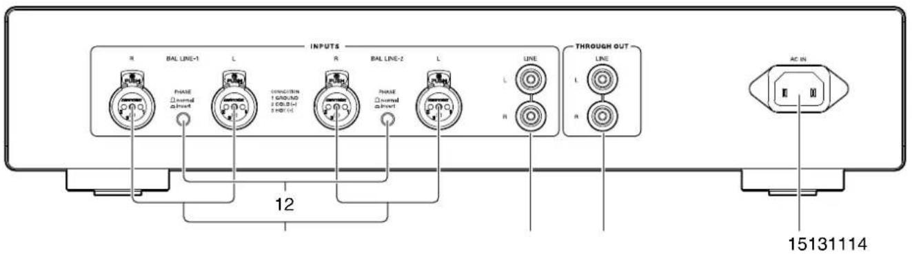
- Input terminals (BAL LINE-1, BAL LINE-2)
Are the balance type input terminals of the LINE level for an XLR connector (Cannon connector)
- Phase switch (PHASE)
Change the phase when the balance input terminal is used. The phase shall be corresponding to the phase of the input device.
Normal position .....①GROUND
②COLD
③HOT
Invert position .....①GROUND
②HOT
③COLD
- Input terminal (LINE)
Line input terminals for RCA connector.
- Output terminal (THROUGH OUT)
Line input signal pass through line output, for connected to other amplifier or sources.
- AC inlet (AC IN)
Connect the accessory power cable.
The power should be obtained from an AC out let.
Memory
After turn off the power supply of the machine, the following content will memory.
THROUGH OUT on/off
OUTPUT MODE UNBAL/BAL
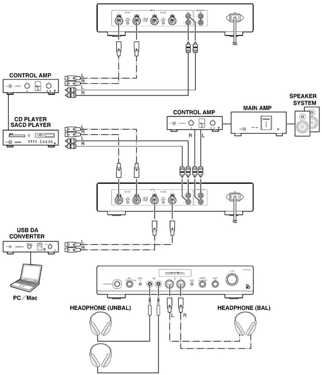
Connections
flowchart
graph TD
    A["PC/Mac"] --> B["USB DA CONVERTER"]
    B --> C["CD PLAYER SACD PLAYER"]
    C --> D["CONTROL AMP"]
    D --> E["SPEAKER SYSTEM"]
    E --> F["MAIN AMP"]
    F --> G["HEADPHONE (BAL)"]
    G --> H["HEADPHONE (UNBAL)"]
    H --> I["HEADPHONE (UNBAL)"]
    I --> J["HEADPHONE (UNBAL)"]
    J --> K["HEADPHONE (UNBAL)"]
    K --> L["HEADPHONE (UNBAL)"]
    L --> M["HEADPHONE (UNBAL)"]
    M --> N["HEADPHONE (UNBAL)"]
    N --> O["HEADPHONE (UNBAL)"]
    O --> P["HEADPHONE (UNBAL)"]
    P --> Q["HEADPHONE (UNBAL)"]
    Q --> R["HEADPHONE (UNBAL)"]
    R --> S["HEADPHONE (UNBAL)"]
    S --> T["HEADPHONE (UNBAL)"]
    T --> U["HEADPHONE (UNBAL)"]
    U --> V["HEADPHONE (UNBAL)"]
    V --> W["HEADPHONE (UNBAL)"]
    W --> X["HEADPHONE (UNBAL)"]
    X --> Y["HEADPHONE (UNBAL)"]
    Y --> Z["HEADPHONE (UNBAL)"]
    Z --> AA["HEADPHONE (UNBAL)"]
    AA --> AB["HEADPHONE (UNBAL)"]
    AB --> AC["HEADPHONE (UNBAL)"]
    AC --> AD["HEADPHONE (UNBAL)"]
    AD --> AE["HEADPHONE (UNBAL)"]
    AE --> AF["HEADPHONE (UNBAL)"]
    AF --> AG["HEADPHONE (UNBAL)"]
    AG --> AH["HEADPHONE (UNBAL)"]
    AH --> AI["HEADPHONE (UNBAL)"]
    AI --> AJ["HEADPHONE (UNBAL)"]
    AJ --> AK["HEADPHONE (UNBAL)"]
    AK --> AL["HEADPHONE (UNBAL)"]
    AL --> AM["HEADPHONE (UNBAL)"]
    AM --> AN["HEADPHONE (UNBAL)"]
    AN --> AO["HEADPHONE (UNBAL)"]
    AO --> AP["HEADPHONE (UNBAL)"]
    AP --> AQ["HEADPHONE (UNBAL)"]
    AQ --> AR["HEADPHONE (UNBAL)"]
    AR --> AS["HEADPHONE (UNBAL)"]
    AS --> AT["HEADPHONE (UNBAL)"]
    AT --> AU["HEADPHONE (UNBAL)"]
    AU --> AV["HEADPHONE (UNBAL)"]
    AV --> AW["HEADPHONE (UNBAL)"]
    AW --> AX["HEADPHONE (UNBAL)"]
    AX --> AY["HEADPHONE (UNBAL)"]
Before making connections
Before connecting other devices, connect the accessory power cable to the AC inlet of this unit. Turn off the power switch of this unit and the power supplies of the connected devices to prevent unexpected noise.
How to connect power supply
Use the accessory power cable and insert the AC plug in an outlet on the wall.
How to connect CD player or other devices
Connect the output terminals of a CD player or TAPE player (rec out) to line input of this unit, used RCA cables or BALANCE cables.
Phone out
Connect for headphone with 80hms or above.
Two sets of headphone can be used.
Through out (line) connection
Input signal pass through line output can be used to connect with amplifier or other devices.
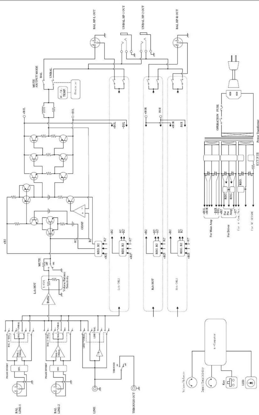
Block Diagram
| Continuous power output | UNBAL 4W + 4W (8Ω), 1W + 1W (32Ω) | |
| BAL 8W + 8W (16Ω), 4W + 4W (32Ω) | ||
| Input sensitivity | LINE → UNBAL : 1V (SENSITIVITY HIGH) | |
| BAL LINE → BAL : 2V (SENSITIVITY HIGH) | ||
| LINE → UNBAL : 2V (SENSITIVITY HIGH) | ||
| BAL LINE → BAL : 1V (SENSITIVITY HIGH) | ||
| Input impedance | LINE :15kΩ (THROUGH OUT OFF) | |
| BAL LINE : 40kΩ | ||
| Total harmonic distortion | LINE → UNBAL : 0.0035% (8Ω, 1kHz, 1W) | |
| BAL LINE → BAL : 0.0020% (16Ω, 1kHz, 1W) | ||
| S/N ratio | LINE → UNBAL : >110dB | |
| BAL LINE → BAL : >115dB | ||
| Frequency response | LINE → UNBAL : 20Hz~20,000Hz (+0, -0.1dB) | |
| : 10Hz~170,000Hz (+0, <-3dB) | ||
| BAL LINE → BAL : 20Hz~20,000Hz (+0, -0.1dB) | ||
| : 10Hz~170,000Hz (+0, <-3dB) | ||
| Accessories | owner's manual | |
| safety cautions | ||
| Power supply voltage | 230V~50Hz | |
| Power consumption | 40W | |
| 27W (at no input) | ||
| Max. external dimensions | 440 (W) x 92 (H) x 400 (D) mm | |
| Net Weight | 12.7kg | |
* Specifications and appearance are subject to change without notice.
Troubleshooting
While the unit is used, an unusual phenomenon may be confused as a malfunction for a certain reason. Prior to asking us for repair services, please check the table below and read the instruction manual for the subsidiary devices. If the cause of the malfunction cannot be identified, please contact your dealer.
Problem Cause Solution
| No power is supplied even though the power switch is pressed | ·The power plug is disconnected from the wall outlet, or it is not completely inserted. | ·Insert the power plug in the wall outlet securely. |
| ·The power plug is disconnected from the AC inlet, or it is not completely inserted. | ·Insert the power plug in the AC inlet securely. | |
| No sound is generated | ·The volume control is set to minimum level. | ·Rotate the volume control clockwise to adjust the sound volume. |
| ·Cable connections are incomplete. | ·Make cable connections securely. | |
| ·The input selector is not set to the input source. | ·Set the input selector to the input source. | |
| ·The output level of the input device is set to the minimum. | ·Adjust the output level. | |
| No sound is generated on one side | ·The balance control of the input source is fully rotated. | ·The balance control shall be set to the center. |
| ·The connecting cable is connected on one side only. | ·Make cable connections securely. | |
| Through out line no signal | ·Through out switch set to off. | ·Set the through out switch to on. |
| Humming sound (boon or zzz noise) is generated | ·The ground side of the pin-plug cable has no contact with the terminal. | ·Make connection securely so that the ground side of the pin-plug cable can be connected. |
| ·Induction noise is picked up from another device. | ·Install it distant from other devices. | |
| ·The power cables are laid too close to the signal cables. | ·Provide sufficient spacing between the power cables and the signal cables. |
