TH-65CQE2U - Screen PANASONIC - Free user manual and instructions
Find the device manual for free TH-65CQE2U PANASONIC in PDF.

| Product Type | 65-inch 4K UHD LED Display |
| Screen Size (diagonal) | 65 inches (163 cm) |
| Resolution | 3840 x 2160 pixels (4K UHD) |
| Panel Technology | IPS LCD with Direct LED backlight |
| Refresh Rate | 60 Hz (native) |
| HDR Support | HDR10, HLG |
| Dimensions (without stand) | 1448 x 835 x 64 mm |
| Dimensions (with stand) | 1448 x 895 x 290 mm |
| Weight (without stand) | 24.5 kg |
| Weight (with stand) | 26.0 kg |
| Power Supply | AC 100-240 V, 50/60 Hz |
| Power Consumption (typical) | 200 W |
| Video Inputs | HDMI x 3, USB x 2, Component, Composite |
| Audio Output | Optical digital, Headphone jack |
| Connectivity | Ethernet, Wi-Fi, Bluetooth |
| Operating System | Smart TV platform (proprietary) |
| Cleaning Instructions | Use a soft, lint-free cloth. Avoid liquid cleaners. |
| Safety Warnings | Do not expose to rain or moisture. Use on stable surface. |
| Spare Parts Availability | Contact Panasonic service centers for genuine parts. |
| Repairability Index | Score 7.5/10 based on ease of disassembly and parts availability. |
| Manufacturer | Panasonic Corporation |
Frequently Asked Questions - TH-65CQE2U PANASONIC
User questions about TH-65CQE2U PANASONIC
0 question about this device. Answer the ones you know or ask your own.
Ask a new question about this device
Download the instructions for your Screen in PDF format for free! Find your manual TH-65CQE2U - PANASONIC and take your electronic device back in hand. On this page are published all the documents necessary for the use of your device. TH-65CQE2U by PANASONIC.
USER MANUAL TH-65CQE2U PANASONIC
Operating Instructions
Functional Manual
UHD LCD Commercial TV
For business use
Model No. TH-86CQ2U 86-inch model
TH-75CQ2U 75-inch model
TH-65CQ2U 65-inch model
TH-55CQ2U 55-inch model
TH-50CQ2U 50-inch model
TH-43CQ2U 43-inch model
natural_image
Blank white rectangle with a thin border and corner markers (no text or symbols)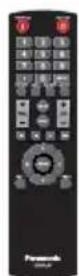
4K
PROFESSIONAL
*Actual resolution: 3840 × 2160p
HDMI™
* This manual is common to all the models regardless of suffixes of the model number.
English
Please read these instructions before operating your set and retain them for future reference.

Advance™
Covered by patents at patent list, access advance.com
DOLBY AUDIO™
Manufactured under license from Dolby Laboratories.
Dolby, Dolby Audio and the double-D symbol are trademarks of Dolby Laboratories.
Dear Panasonic Customer
Welcome to the Panasonic family of customers. We hope that you will have many years of enjoyment from your new UHD LCD TV.
To obtain maximum benefit from your set, please read these Instructions before making any adjustments, and retain them for future reference.
Retain your purchase receipt also, and note down the model number and serial number of your set in the space provided on the rear cover of these instructions.
Visit our Panasonic Web Site
https://panasonic.net/cns/prodisplays/

ENERGY STAR is a program run by the U. S.
Environmental Protection Agency (EPA) and U. S. Department of Energy (DOE) that promotes energy efficiency.
This product qualifies for ENERGY STAR in the “factor default” settings and this is the setting in which power savings will be achieved.
Changing the factory default picture settings or enabling other features will increase power consumption that could exceed the limits necessary to qualify for ENERGY STAR rating.
For more information on the ENERGY STAR program, refer to energystar. gov.
- This program applies only to TH-43CQ2U and TH-65CQ2U.
Table of Contents
Before use
- Illustrations and screens in this Operating Instructions are images for illustration purposes, and may be different from the actual ones.
- Descriptive illustrations in this Operating Instructions are created mainly based on the 55-inch model.
Important Safety Instructions......4
FCC STATEMENT......5
Important Safety Notice....6
Safety Precautions....8
Precautions for use....11
Accessories ....13
Accessories Supply 13
Remote Control Batteries 13
Cautions when moving ....14
Kensington security....14
Eyebolt 15
Connections......16
AC cord connection and fixing / Cable fixing …… 16
Video equipment connection 17
Before connecting 18
HDMI IN 1, HDMI IN 2 and HDMI IN 3 terminals connection....18
PC IN terminal connection 19
RS232 terminal connection 20
AUDIO OUT terminal connection 22
Antenna connection....22
USB terminal connection 23
Identifying Controls....24
Display 24
Remote Control Transmitter 25
Basic Controls 26
Selecting the input signal 27
DISPLAY....28
Volume Adjustment 28
Sound mute On / Off 28
ASPECT Controls 29
On-Screen Menu Displays ....30
Picture Adjustments....32
Sound Adjustment....33
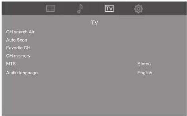
TV Adjustment ....34
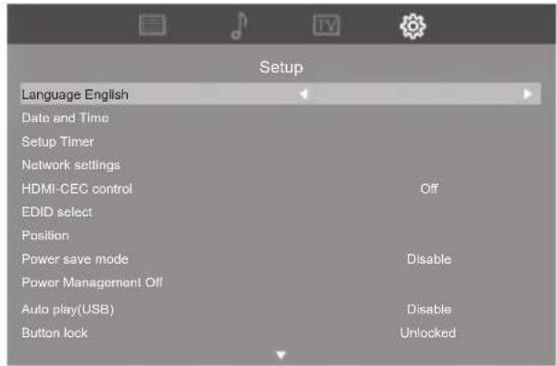
Setup menu....35
Language 35
Date and Time 35
Setup Timer 35
Network settings 36
HDMI-CEC control 37
EDID select 37
Position 38
Power save mode 38
Power Management 38
Auto play(USB) 39
Button lock 39
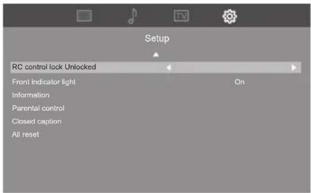
RC control lock 39
Front indicator light 39
Information 39
Parental control 40
Closed caption 42
All reset 42
Using Network Function 43
Necessary environment for computers to be connected · 43
Example of network connection 43
Settings to connect to a LAN 44
Preparation for PJLink control....44
PJLink protocol 45
Multi Monitoring & Control Software 46
Using "USB media file playback function" .. 47
Play file....48
Auto playback 48
Playing the pictures 49
Playing the music / video 50
Using HDMI-CEC function .....51
Connection 51
Setting 51
Preset Signals....52
Troubleshooting ....54
Specifications ....56

WARNING: To reduce the risk of electric shock, do not remove cover or back.
No user-serviceable parts inside. Refer servicing to qualified service personnel.

The lightning flash with arrow-head within a triangle is intended to tell the user that parts inside the product are a risk of electric shock to persons.

The exclamation point within a triangle is intended to tell the user that important operating and servicing instructions are in the papers with the appliance.
WARNING:
To prevent damage which may result in fire or shock hazard, do not expose this apparatus to rain or moisture.
Do not place containers with water (flower vase, cups, cosmetics, etc.) above the set.
(including on shelves above, etc.)
WARNING:
1) To prevent electric shock, do not remove cover. No user serviceable parts inside. Refer servicing to qualified service personnel.
2) Do not remove the grounding pin on the power plug. This apparatus is equipped with a three pin grounding-type power plug. This plug will only fit a grounding-type power outlet. This is a safety feature. If you are unable to insert the plug into the outlet, contact an electrician.
Do not defeat the purpose of the grounding plug.
Important Safety Instructions
1) Read these instructions.
2) Keep these instructions.
3) Heed all warnings.
4) Follow all instructions.
5) Do not use this apparatus near water.
6) Clean only with dry cloth.
7) Do not block any ventilation openings. Install in accordance with the manufacturer's instructions.
8) Do not install near any heat sources such as radiators, heat registers, stoves, or other apparatus (including amplifiers) that produce heat.
9) Do not defeat the safety purpose of the polarized or grounding-type plug. A polarized plug has two blades with one wider than the other. A grounding type plug has two blades and a third grounding prong. The wide blade or the third prong are provided for your safety. If the provided plug does not fit into your outlet, consult an electrician for replacement of the obsolete outlet.
10) Protect the power cord from being walked on or pinched particularly at plugs, convenience receptacles, and the point where they exit from the apparatus.
11) Only use attachments / accessories specified by the manufacturer.
12) Use only with the cart, stand, tripod, bracket, or table specified by the manufacturer, or sold with the apparatus. When a cart is used, use caution when moving the cart / apparatus combination to avoid injury from tip-over.
13) Unplug this apparatus during lightning storms or when unused for long periods of time.
14) Refer all servicing to qualified service personnel. Servicing is required when the apparatus has been damaged in any way, such as power-supply cord or plug is damaged, liquid has been spilled or objects have fallen into the apparatus, the apparatus has been exposed to rain or moisture, does not operate normally, or has been dropped.
15) To prevent electric shock, ensure the grounding pin on the AC cord power plug is securely connected.
16) If an outside antenna is connected to the receiver, confirm that the antenna system is grounded to protect against voltage surges and built up static charges. Section 810 of the National Electrical Code, ANSI/NFPA 70-1984, provides information with respect to proper grounding of the mast and supporting structure, grounding of the lead-in wire to an antenna discharge unit, size of grounding connectors, location of antenna discharge unit, connection to grounding electrodes, and requirements for the grounding electrode.

The cable distribution system should be grounded (earthed) in accordance with ANS/NFPA 70. the National Electrical Code (NEC), in particular Section 820.93, Grounding of Outer Conductive Shield of a Coaxial Cable.
EXAMPLE OF ANTENNA GROUNDING AS PER (NEC) NATIONAL ELECTRICAL CODE
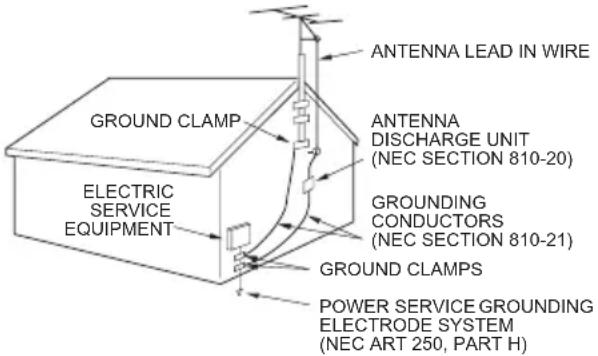
- Lightning — For added protection for this television equipment during a lightning storm, or when it is left unattended and unused for long periods of time, unplug it from the wall outlet and disconnect the antenna. This will prevent damage to the equipment due to lightning and power-line surges.
- Power Lines — An outside antenna system should not be located in the vicinity of overhead power lines or other electric light or power circuits, or where it can fall into such power lines or circuits. When installing an outside antenna system, extreme care should be taken to keep from touching such power lines or circuits as contact with them might be fatal.
17) An outside antenna system should not be located in the vicinity of overhead, power lines, other electric light, power circuits, or where it can fall into such power lines or circuits. When installing an outside antenna system, extreme care should be taken to keep from touching such power lines or circuits as contact with them might be fatal.
FCC STATEMENT
This equipment has been tested and found to comply with the limits for a class B digital device, pursuant to part 15 of the FCC Rules. These limits are designed to provide reasonable protection against harmful interference in a residential installation.
This equipment generates, uses and can radiate radio frequency energy and, if not installed and used in accordance with the instructions, may cause harmful interference to radio communications. However, there is no guarantee that interference will not occur in a particular installation. If this equipment does cause harmful interference to radio or television reception, which can be determined by turning the equipment off and on, the user is encouraged to try to correct the interference by one or more of the following measures:
- Reorient or relocate the receiving antenna.
- Increase the separation between the equipment and receiver.
- Connect the equipment into an outlet on a circuit different from that to which the receiver is connected.
- Consult the dealer or an experienced radio/TV technician for help.
FCC CAUTION:
To assure continued compliance, follow the attached installation instructions and use only the provided power supply cord. Any changes or modifications not expressly approved by Panasonic Corp. of North America could void the user's authority to operate this device.
Supplier's Declaration of Conformity
Model No.
TH-86CQ2U, TH-75CQ2U, TH-65CQ2U,
TH-55CQ2U, TH-50CQ2U, TH-43CQ2U
Responsible Party:
Panasonic Corporation of North America
Two Riverfront Plaza, Newark, New Jersey
07102-5490
Contact Source:
Panasonic System Solutions Company of North America
1-877-655-2357
General Contact:
http://shop.panasonic.com/support
This device complies with Part 15 of the FCC Rules and all applicable IC RSS standards. Operation is subject to the following two conditions: (1) This device may not cause harmful interference, and (2) this device must accept any interference received, including interference that may cause undesired operation.
To maintain compliance with EMC regulations, use shielded cables to connect to the following terminals: HDMI input terminal, D-sub input terminal and RS-232C input terminal.
CANADIAN NOTICE:
This Class B digital apparatus complies with Canadian ICES-003.
WARNING:
- Not for use in a computer room as defined in the Standard for the Protection of Electronic Computer/Data Processing Equipment, ANSI/NFPA 75.
- For permanently connected equipment, a readily accessible disconnect device shall be incorporated in the building installation wiring.
- For pluggable equipment, the socket-outlet shall be installed near the equipment and shall be easily accessible.
Note:
Image retention may occur. If you display a still picture for an extended period, the image might remain on the screen. However, it will disappear when a general moving picture is displayed for a while.
Trademark Credits
- Microsoft, Windows, Internet Explorer and Microsoft Edge are the registered trademarks or trademarks of Microsoft Corporation in the United States and/or other countries.
• Mac, macOS and Safari are the trademarks of Apple Inc. registered in the United States and other countries. - PJLink is a registered or pending trademark in Japan, the United States, and other countries and regions.
- HDMI, High-Definition Multimedia Interface and the HDMI Logo are trademarks or registered trademarks of HDMI Licensing Administrator, Inc. in the United States and other countries.
- Manufactured under license from Dolby Laboratories. Dolby, Dolby Audio and the double-D symbol are trademarks of Dolby Laboratories.
Even if no special notation has been made of company or product trademarks, these trademarks have been fully respected.
Important Safety Notice
WARNING
1) To prevent damage which may result in fire or shock hazard, do not expose this appliance to dripping or splashing.
Do not place containers with water (flower vase, cups, cosmetics, etc.) above the set. (including on shelves above, etc.)
No naked flame sources, such as lighted candles, should be placed on / above the set.
2) To prevent electric shock, do not remove cover. No user serviceable parts inside. Refer servicing to qualified service personnel.
3) Do not remove the earthing pin on the power plug. This apparatus is equipped with a three pin earthing-type power plug. This plug will only fit an earthing-type power outlet. This is a safety feature. If you are unable to insert the plug into the outlet, contact an electrician.
Do not defeat the purpose of the earthing plug.
4) To prevent electric shock, ensure the earthing pin on the AC cord power plug is securely connected.
CAUTION
This appliance is intended for use in environments which are relatively free of electromagnetic fields. Using this appliance near sources of strong electromagnetic fields or where electrical noise may overlap with the input signals could cause the picture and sound to wobble or cause interference such as noise to appear.
To avoid the possibility of harm to this appliance, keep it away from sources of strong electromagnetic fields.
WARNING
Stability Hazard
A TV set may fall, causing serious personal injury or death. Many injuries, particularly to children, can be avoided by taking simple precautions such as:
- ALWAYS use cabinets or stands or mounting methods recommended by the manufacturer of the TV set.
- ALWAYS use furniture that can safely support the TV set.
- ALWAYS ensure the TV set is not overhanging the edge of the supporting furniture.
- ALWAYS educate children about the dangers of climbing on furniture to reach the TV set or its controls.
- ALWAYS route cords and cables connected to your TV so they cannot be tripped over, pulled or grabbed.
- NEVER place a TV set in an unstable location.
- NEVER place the TV set on tall furniture (for example, cupboards or bookcases) without anchoring both the furniture and the TV to a suitable support.
- NEVER place the TV set on cloth or other materials that may be located between the TV set and supporting furniture.
- NEVER place items that might tempt children to climb, such as toys and remote controls, on the top of the TV or furniture on which the TV is placed.
If the existing TV set is going to be retained and relocated, the same considerations as above should be applied.
The cable distribution system should be grounded (earthed) in accordance with ANSI/NFPA 70. the National Electrical Code (NEC), in
particular Section 820.93, Grounding of Outer Conductive Shield of a Coaxial Cable.
This equipment is not suitable for use in locations where children are likely to be present.
Safety Precautions
WARNING
Setup
This LCD TV is for use only with the following optional accessories.
Use with any other type of optional accessories may cause instability which could result in the possibility of injury.
Securely install the pedestal and wall hanging bracket of the optional accessories. Ask an authorized dealer for installation.
The following number of people are required for installation.
| 86-inch model | 75-inch model | 4 or more |
| 65-inch model | 55-inch model | 50-inch model |
| 43-inch model | 2 or more | |
- Pedestal
75-inch model 65-inch model : TY-ST75PE9
55-inch model : TY-ST55PE9
50-inch model 43-inch model: TY-ST43PE9*1
• Wall hanging bracket*2
86-inch model 75-inch model 65-inch model
TY-WK98PV1
• Early Warning Software
(Basic license/3-year license):
ET-SWA100 series ^4
*1: When the Pedestal (TY-ST43PE9) is installed with the 43-inch model, the Kensington security slot cannot be used.
*2: This product can be purchased in the U.S. and Japan.
*3: Suffix of the part number may differ depending on the license type.
Note
- The part number of the optional accessories are subject to change without notice.
86-inch model 75-inch model 65-inch model
When attaching the wall hanging bracket, be sure to remove the 2 lower handles.
When installing the pedestal or wall hanging bracket, read the operating instructions supplied with it carefully and install properly. Also, be sure to take a fall-prevention measure.
We are not responsible for any product damage, etc. caused by failures in the installation environment for the pedestal or wall hanging bracket even during the warranty period.
Small parts can present choking hazard if accidentally swallowed. Keep small parts away from young children. Discard unneeded small parts and other objects, including packaging materials and plastic bags/sheets to prevent them from being played with by young children, creating the potential risk of suffocation.
Do not place the TV on sloped or unstable surfaces, and ensure that the TV does not hang over the edge of the base.
• The TV may fall off or tip over.
Install this unit at a location with minimal vibration and which can support the weight of the unit.
- Dropping or falling of the unit may cause injury or malfunction.
Caution - For use only with UL Listed Wall Mount Bracket with minimum weight/load, please refer to the Specifications. (see page 57)
- If installed in different directions, heat is generated and it may cause fire or damage to the TV.
Cautions for Wall or Pedestal Installation
- The installation should be performed by an installation professional. Installing the TV incorrectly may lead to an accident that results in death or serious injury. Use the optional Pedestal. (see page 8)
- When installing on a wall, the specified wall hanging bracket (optional accessory) or a wall hanging bracket that conforms to VESA standards must be used.
86-inch model : VESA 600 × 400
75-inch model : VESA 600 × 400
65-inch model : VESA 400 × 400
55-inch model : VESA 400 × 400
50-inch model : VESA 400 × 400
43-inch model : VESA 200 × 200
(see page 11)
- Before installation, be sure to check if the mounting location has enough strength to support the weight of the TV and the wall hanging bracket for anti drop.
- If you terminate the use of the product, ask a professional to remove it promptly.
- When mounting the TV on the wall, prevent the mounting screws and power cable from contacting metal objects inside the wall. An electric shock may occur if they contact metal objects inside the wall.
■ When using the LCD TV
The TV is designed to operate on 110 - 127 V, 60 Hz.
If problems or malfunction occur, stop using immediately.
If problems occur, unplug the power supply plug.
- Smoke or an abnormal odour come out from the unit.
- No picture appears or no sound is heard, occasionally.
- Liquid such as water or foreign objects got inside the unit.
• The unit has deformed or broken parts.
If you continue to use the unit in this condition, it could result in fire or electric shock.
- Unplug the power supply plug from the wall outlet, and then contact the dealer for repairs.
- To cut off the power supply to this TV completely, you need to unplug the power supply plug from the wall outlet.
- Repairing the unit yourself is dangerous, and shall never be done.
- To enable to unplug the power supply plug immediately, use the wall outlet which you can reach easily.
Do not touch the unit directly by hand when it is damaged.
• Electric shock could occur.
Do not stick any foreign objects into the TV.
- Do not insert any metal or flammable objects into the ventilations holes or drop them onto the TV, as doing so can cause fire or electric shock.
Do not remove the cover (cabinet) or modify it.
- High voltages which can cause fire or electric shocks are present inside the TV. For any inspection, adjustment and repair work, please contact your local Panasonic dealer.
Ensure that the mains plug is easily accessible.
The mains plug shall be connected to a mains socket outlet with a protective earthing connection.
Do not use any power supply cord other than that provided with this unit.
- Doing so may cause short-circuit, generates heat, etc., which could cause electric shock or fire.
Do not use the supplied power supply cord with any other devices. - Doing so may cause short-circuit, generates heat, etc., which could cause electric shock or fire.
Clean the power supply plug regularly to prevent it becoming dusty.
- If there is a build up of dust on the plug, the resultant humidity may cause short-circuit, which could cause electric shock or fire. Unplug the power supply plug from the wall outlet and wipe it with a dry cloth.
Do not handle the power supply plug with wet hands.
- Doing so may cause electric shocks.
Securely insert the power supply plug (socket outlet side) and the power supply connector (main unit side) as far as it will go.
- If the plug is not fully inserted, heat may be generated which could cause fire. If the plug is damaged or the wall socket is loose, they shall not be used.
Do not do anything that may damage the power supply cord or the power supply plug.
- Do not damage the cable, make any modifications to it, place heavy objects on top of it, heat it, place it near any hot objects, twist it, bend it excessively or pull it. To do so may cause fire and electric shock. If the power cable is damaged, have it repaired at your local Panasonic dealer.
Do not touch the power supply cord or the plug directly by hand when they are damaged.
- Doing so may cause electric shock or fire due to short-circuit.
Keep the supplied AAA batteries out of reach of children. If accidentally swallowed, it will be harmful to the body.
- Please contact a doctor immediately in case you doubt that the child may have swallowed it.
To prevent the spread of fire, keep candles or other open flames away from this product at all times.

CAUTION
Do not place any objects on top of the TV.
Ventilation should not be impeded by covering the ventilation openings with items such as newspapers, table cloths and curtains.
- Doing so may cause the TV to overheat, which can cause fire or damage to the TV.
For sufficient ventilation, see page 11.
Do not place the TV where it may be affected by salt or corrosive gas.
- Doing so may cause the TV to fall due to corrosion, and it may result in injury. Also, the unit may malfunction.
The following number of people are required to carry or unpack this unit.
| 86-inch model | 75-inch model | 4 or more |
| 65-inch model | 55-inch model | 50-inch model |
| 43-inch model | 2 or more | |
- If this is not observed, the unit may drop, resulting in injury.
When disconnecting the power supply cord, always pull on the plug (socket outlet side) / the connector (main unit side).
- Pulling the cord may damage the cord, and it may cause electric shock or fire due to short-circuit.
Be sure to disconnect all cables before moving the TV.
- If the TV is moved while some of the cables are still connected, the cables may become damaged, and fire or electric shock could result.
Disconnect the power supply plug from the wall socket as a safety precaution before carrying out any cleaning.
• Electric shocks can result if this is not done.
Do not step on, or hang from the TV or the Pedestal.
- They might tip over, or might be broken and it may result in injury. Pay special attention to the children.
Do not reverse the polarity (+ and -) of the battery when inserting.
- Mishandling the battery may cause its explosion or leakage, resulting in fire, injury or damage to surrounding properties.
- Insert the battery correctly as instructed. (see page 13)
Do not use batteries with the outer cover peeling away or removed.
- Mishandling the batteries may cause the batteries to short circuit, resulting in fire, injury or damage to surrounding properties.
Remove the batteries from the remote control transmitter when not using for a long period of time.
- The battery may leak, heat, ignite or burst, resulting in fire or damage to surrounding properties.
Remove exhausted batteries from the remote control immediately.
• Leaving the batteries unattended in it may cause battery leakage, heat or burst.
Do not burn or breakup batteries.
- Batteries must not be exposed to excessive heat such as sunshine, fire or the like.
Do not turn the TV upside down.
Do not position the unit with its liquid crystal panel facing upright.
Precautions for use
Cautions when installing
Do not set up the TV outdoors.
• The TV is designed for indoor use.
Install this unit at a location which can support the weight of the unit.
- Dropping or falling of the unit may cause injury.
Environmental temperature to use this unit
- When using the unit where it is below 1 400 m (4 593 ft) above sea level: 0 °C to 40 °C (32 °F to 104 °F)
- When using the unit at high altitudes (1 400 m (4 593 ft) and higher and below 2 800 m (9 186 ft) above sea level): 0 °C to 35 °C (32 °F to 95 °F)
Do not install the unit where it is 2 800 m (9 186 ft) and higher above sea level.
- Failure to do so may shorten the life of the internal parts and result in malfunctions.
We are not responsible for any product damage, etc. caused by failures in the installation environment even during the warranty period.
Transport only in upright position!
- Transporting the unit with its liquid crystal panel facing upright or downward may cause damage to the internal circuitry.
Do not grab the liquid crystal panel.
- Do not forcibly press the liquid crystal panel, or push it with a pointed object. Applying a strong force to the liquid crystal panel will cause unevenness of the screen display, resulting in malfunction.
Do not install the product to a place where the product is exposed to direct sunlight.
- If the unit is exposed to direct sunlight even indoors, the temperature rise of the liquid crystal panel may cause malfunction.
In the case of storage, store the unit in a dry room.
Required space for ventilation
- Operation of this unit is guaranteed up to an ambient temperature of 40 °C (104 °F). When installing the unit in a case or chassis, be sure to provide adequate ventilation with a cooling fan or ventilation hole so that the surrounding temperature (inside the case or chassis) including the temperature of the front surface of the liquid crystal panel can be kept at 40 °C (104 °F) or less.
About the screws used when using a wall hanging bracket that conforms to VESA standards
Depth of screw hole
Screw for fixing the TV onto the wall-hanging bracket (not supplied with the TV)
- Make sure that all screws are securely tightened.
(View from the side)
| Inch model | Screw pitch for installation | Depth of screw hole | Screw (quantity) |
| 86 600 mm × 400 mm 20 mm M8 (4) | |||
| 75 600 mm × 400 mm 20 mm M8 (4) | |||
| 65 400 mm × 400 mm 20 mm M8 (4) | |||
| 55 400 mm × 400 mm 18 mm M6 (4) | |||
| 50 400 mm × 400 mm 20 mm M6 (4) | |||
| 43 200 mm × 200 mm 16 mm M6 (4) |
Note for connection
Removing and inserting the power cord and connection cables
- When the unit has been installed on the wall, if the power cord and connection cables are difficult to remove and insert, make connections first before installation. Be careful not to allow the cables to be entangled. After installation is completed, insert the power plug to the outlet.
When using
Red, blue or green dots on the screen are a liquid crystal panel-specific phenomenon. This is not a malfunction.
- Although the liquid crystal display is manufactured with high-precision technology, always-lighting dots or non-lighting dots may appear on the screen. This is not a malfunction.
| Inch model Dot omission ratio | * |
| 86 0.00007% or less | |
| 75 0.00007% or less | |
| 65 0.00005% or less | |
| 55 0.00005% or less | |
| 50 0.00005% or less | |
| 43 0.00005% or less |
*: Calculated in sub-pixel units according to the ISO09241-307 standard.
Depending on the temperature or humidity conditions, uneven brightness may be observed. This is not a malfunction.
- This unevenness will disappear while applying current continuously. If not, consult the distributor.
If the TV is not going to be used for any prolonged length of time, unplug the power supply plug from the wall outlet.
- When storing the product for long periods with no power supplied, do not store it in a location exposed to direct sunlight.
Picture noise may occur if you connect / disconnect the cables connected to the input terminals you are currently not watching, or if you turn the power of the video equipment on / off, but it is not a malfunction.
Notes on Using Wired LAN
When setting up the TV at a place, where electric statistic occurs often, take a sufficient antistatic measure before start using.
- When the TV is used at a location, where static electricity occurs often, such as on a carpet, a wired LAN communication is disconnected more often. In that case, remove static electricity and the noise source that may cause problems with an antistatic mat, and re-connect the wired LAN.
- In rare cases, the LAN connection is disabled due to static electricity or noise. In that case, turn off the power of the TV and the connected devices once and then re-turn on the power.
The TV may not work properly due to strong radio wave from the broadcast station or the radio. (see page 44)
- If there is any facility or equipment, which outputs strong radio wave, near the installation location, set up the TV at a location sufficiently far from the source of the radio wave. Or, wrap the LAN cable connected to the LAN terminal by using a piece of metal foil or a metal pipe, of which is grounded at both ends.
Request Regarding Security
When using this unit, take safety measures against the following incidents.
• Personal information being leaked via this unit
- Unauthorized operation of this unit by a malicious third party
- Interfering or stopping of this unit by a malicious third party
Take sufficient security measures.
- Set a password for LAN control and restrict the user who performs the control.
- Make your password difficult to guess as much as possible.
- Change your password periodically.
- Panasonic Corporation or its affiliate companies will never ask for your password directly. Do not divulge your password in case you receive such inquiries.
- The connecting network must be secured by a firewall, etc.
- When disposing the product, initialize the data before disposing.
Cleaning and maintenance
First, remove the mains plug from the mains socket. Gently wipe the surface of the liquid crystal panel or cabinet by using a soft cloth to remove dirt.
- To remove stubborn dirt or fingerprints on the surface of the liquid crystal panel, dampen a cloth with diluted neutral detergent (1 part detergent to 100 parts water), wring out the cloth firmly, and then wipe away the dirt. Finally, wipe away all the moisture with a dry cloth.
- If water droplets get inside the unit, operating problems may result.
Note
- The surface of the liquid crystal panel is specially treated. Do not use a hard cloth or rub the surface too hard, otherwise this may cause scratches on the surface.
Usage of a chemical cloth
- Do not use a chemical cloth for the liquid crystal panel surface.
- Follow the instructions for the chemical cloth to use it for the cabinet.
Avoid contact with volatile substances such as insect sprays, solvents and thinner.
- This may cause damage to the cabinet or cause peeling of the paint. Furthermore, do not leave it in contact with a rubber or PVC substance for a long time.
Disposal
When disposing the product, ask your local authority or dealer about the correct methods of disposal.
Accessories
Accessories Supply
Check that you have the accessories and items shown.
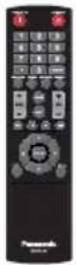
Remote Control Transmitter
× 1
DPVF2598ZC/X1
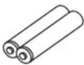
Batteries for the Remote
Control Transmitter × 2
(AAA type)
Power supply cord
(Approx. 2 m)
1JP143CQ2U
natural_image
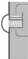
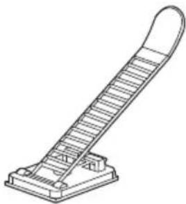
Illustration of a coiled electrical plug with two terminal connectors (no text or symbols)Clamper (large) × 2
- DPVF1654ZA
natural_image
Line drawing of a staircase with a curved top and base (no text or symbols)Attention
- Store small parts in an appropriate manner, and keep them away from young children.
- The part numbers of accessories are subject to change without notice. (The actual part number may differ from the ones shown above.)
- In case you lost accessories, please purchase them from your dealer. (Available from the customer service)
- Dispose the packaging materials appropriately after taking out the items.
Remote Control Batteries
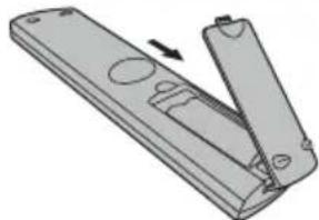
natural_image
Diagram of a remote control panel with an open lid and internal slots, showing no text or symbols.Open the battery cover.
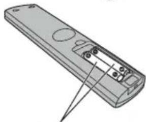
natural_image
Illustration of a remote control device with a pointed tip indicating the handle (no text or symbols present)Insert batteries and close the battery cover.
(Insert starting from the ⊖ side.)
AAA type
Note
- Incorrect installation of the batteries can cause battery leakage and corrosion that will damage the remote control.
- Disposal of batteries should be done in an environment-friendly manner.
Take the following precautions.
- Batteries shall always be replaced as a pair.
- Do not combine a used battery with a new one.
- Do not mix battery types (example; manganese dioxide battery and alkaline battery etc.).
- Do not attempt to charge, disassemble or burn used batteries.
- Do not burn or breakup batteries.
Moreover, batteries must not be exposed to excessive heat such as sunshine, fire or the like.
Cautions when
moving
86-inch model
75-inch model
65-inch model
The TV has handles for carrying. Hold them when moving.
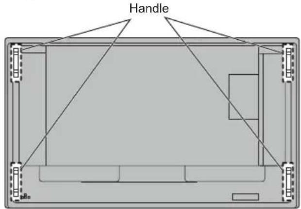
Note
- Do not hold parts other than the handles.
- The following number of people are required to carry this unit.
| 86-inch model | 75-inch model | 4 or more |
| 65-inch model | 55-inch model | 50-inch model |
| 43-inch model | 2 or more | |
If this is not observed, the unit may drop, resulting in injury.
- When carrying the unit, keep the liquid crystal panel upright.
Carrying the unit with the surface of the liquid crystal panel facing up or down may cause deformation of the panel, or internal damage.
- Do not hold the upper, lower, right and left frames or the corners of the unit. Do not hold the front surface of the liquid crystal panel. Also, do not hit such parts. Doing so may damage the liquid crystal panel.
Also, the panel may crack, resulting in injury.
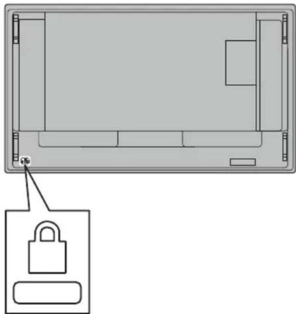
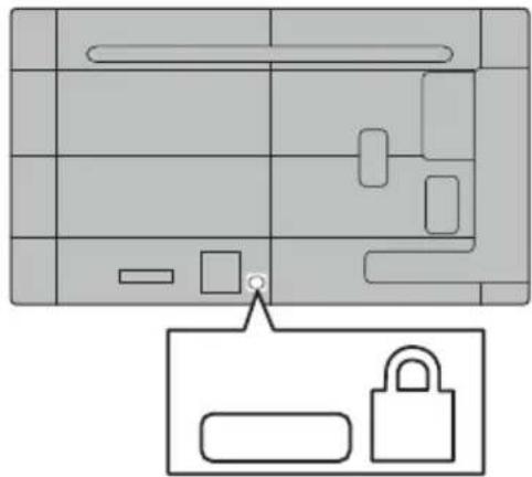
Kensington security
The security slot of this unit is compatible with the Kensington security slot.
86-inch model 75-inch model 65-inch model
natural_image
Top-down diagram of a device casing with a lock icon and a small labeled component (no text or symbols)55-inch model 50-inch model 43-inch model
natural_image
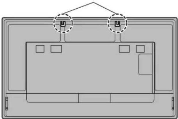
Diagram showing a device layout with a lock icon and a location pin (no text or symbols)Eyebolt
86-inch model
75-inch model
The TV has holes for attaching eyebolts (M10). When installing, use them to suspend the TV Use the eyebolt only for temporary suspension or movement for installation. This cannot be used for permanent hanging installation.
Eyebolt (commercially available) mounting positions
natural_image
Diagram of a device layout with two circular annotations highlighting specific components (no text or symbols present)Attach the eyebolt on the eyebolt mounting position (two locations).
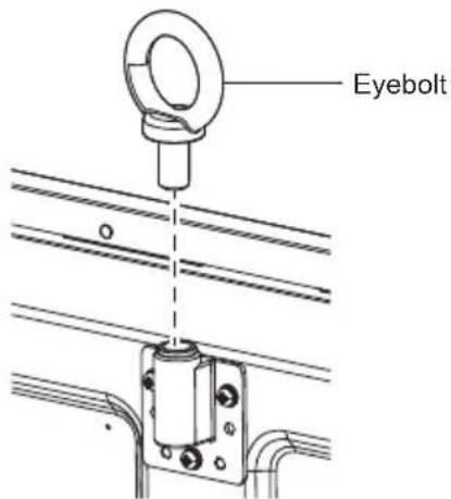
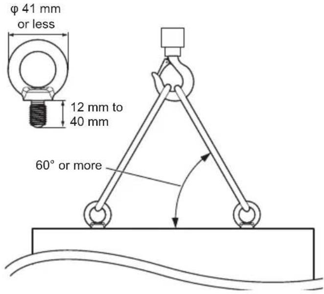
Note
• Installation should be performed by an installation professional.
- Do not suspend using only 1 eyebolt.
- Use commercially sold M10 eyebolts with a shank length of 12 mm to 40 mm that satisfies the load condition of product quality.
- Use ISO 3266 standard eyebolts. Also use ISO standard members (wire, etc.) for hanging.
• The hanging angle should be 60^ or more.
Connections
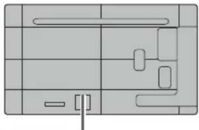
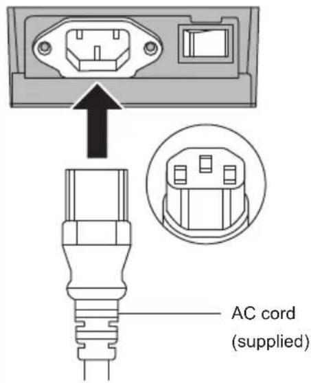
AC cord connection and fixing / Cable fixing
Back of the unit
natural_image
Pure architectural floor plan lines without any text, numbers, or symbolsInsert the AC cord securely all the way seated on the back side of the unit.
Note
- When disconnecting the AC cord, be absolutely sure to disconnect the AC cord plug at the socket outlet first.
- The supplied AC cord is for this unit exclusive use. Do not use this for other purposes.
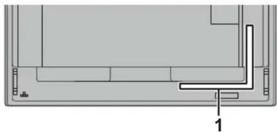
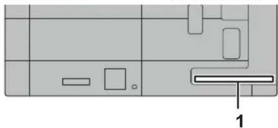
Cable fixing
Note
- 2 clampers are supplied with this unit. Fix the cables at location as shown below. If you need more clampers, purchase them from your dealer. (Available from the customer service)
86-inch model 75-inch model 65-inch model
natural_image
Technical line drawing of a mechanical component with no visible text or symbols55-inch model 50-inch model 43-inch model
natural_image
Pure diagram of a rectangular layout with internal geometric shapes and an arrow pointing to a labeled section (no text or symbols)1 For signal cable: clamper
1. Attach the clamper
Note
- Wipe off dirt, such as dust, water and oil on the attachment surface, and affix the clamper on the attachment surface by pushing it firmly.
- Once the clamper is affixed, it cannot be reused. Be sure to confirm the attaching position before affixing it.
Remove the tape at the back, and affix the clamper on the flat surface.

2. Bundle the cables

To loosen:
Remove the band from the knob, and pull out the band tip.
Video equipment connection
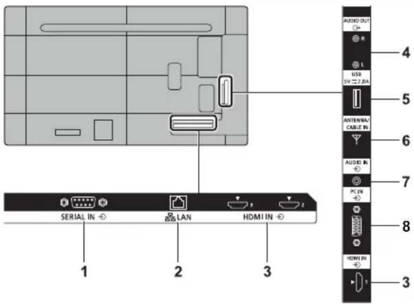
1 SERIAL IN: SERIAL Input Terminal
Control the TV by connecting to PC.
(see page 20)
2 LAN: LAN Terminal
Control the TV by connecting to Network.
(see page 43)
3 HDMI IN 1,
HDMI IN 2, HDMI IN 3:
HDMI Input Terminal
Connect to video equipment such as VCR or DVD player, etc. (see page 18)
- Use a commercially available HDMI cable (conforming to the HDMI standard) that supports 4K.
4 AUDIO OUT: Analogue Audio Output
Terminal
Connect to audio equipment with analogue audio input terminal.
(see page 22)
5 USB: USB Terminal
Connect the USB memory to use "USB media file playback function". Also, this can be used to supply power of up to 5 V / 2 A to an external device when the picture is displayed. (see page 23)
6 ANTENNA/
CABLE IN:
Antenna Terminal
Connect to antenna cable (see page 22)
7 AUDIO IN: Audio Input Terminal
8 PC IN: PC Input Terminal
Connect to video terminal of PC. (see page 19)
Before connecting
- Before connecting cables, carefully read the operating instructions for the external device to be connected.
- Turn off the power of all devices before connecting cables.
- Take note of the following points before connecting the cables. Failure to do so may result in malfunctions.
- When connecting a cable to the unit or a device connected to the unit itself, touch any nearby metallic objects to eliminate static electricity from your body before performing work.
- Do not use unnecessarily long cables to connect a device to the unit or to the unit body. The longer the cable, the more susceptible to noise it becomes. Since using a cable while it is wound makes it act like an antenna, it is more susceptible to noise.
- When connecting cables, insert them straight into the connecting terminal of the connecting device so that the ground is connected first.
- Acquire any cable necessary to connect the external device to the system that is neither supplied with the device nor available as an option.
- If the outer shape of the plug of a connection cable is large, it may come in contact with the periphery such as a back cover or the plug of an adjacent connection cable. Use a connection cable with the suitable plug size for the terminal alignment.
- When connecting the LAN cable with plug cover, be aware that the cover may come in contact with the back cover and it may be difficult to disconnect.
• Some PC models are not compatible with the unit.
- Use cable compensator when you connect devices to the unit using long cables. Otherwise the image may not be displayed properly.
- Refer to "Preset Signals" (see page 52) for the types of video signals that can be displayed with the unit.
HDMI IN 1, HDMI IN 2 and HDMI IN 3 terminals connection
Note
- Video equipment and HDMI cable shown are not supplied with this unit.
- Connect the equipment complying with the HDMI standard.
- Some HDMI equipment may not be able to display picture.
• This TV does not support VIERA LINK.
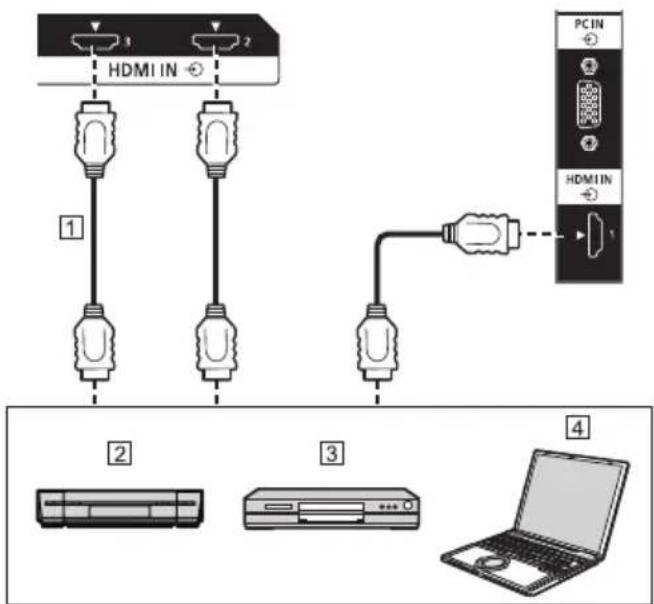
① HDMI cable (commercially available)
② Video Cassette Recorder
③ DVD Player
4 PC
Pin assignments and signal names for HDMI Terminal
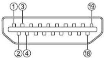
| Pin No. Signal name | |
| 1 | T.M.D.S Data2 + |
| 2 | T.M.D.S Data2 Shield |
| 3 | T.M.D.S Data2 - |
| 4 | T.M.D.S Data1 + |
| 5 | T.M.D.S Data1 Shield |
| 6 | T.M.D.S Data1 - |
| 7 | T.M.D.S Data0 + |
| 8 | T.M.D.S Data0 Shield |
| 9 | T.M.D.S Data0 - |
| 10 | T.M.D.S Clock + |
| 11 | T.M.D.S Clock Shield |
| 12 | T.M.D.S Clock - |
| 13 | CEC |
| 14 | —— |
| 15 | SCL |
| 16 | SDA |
| 17 | DDC/CEC Ground |
| 18 | +5 V DC |
| 19 | Hot Plug Detect |
PC IN terminal connection
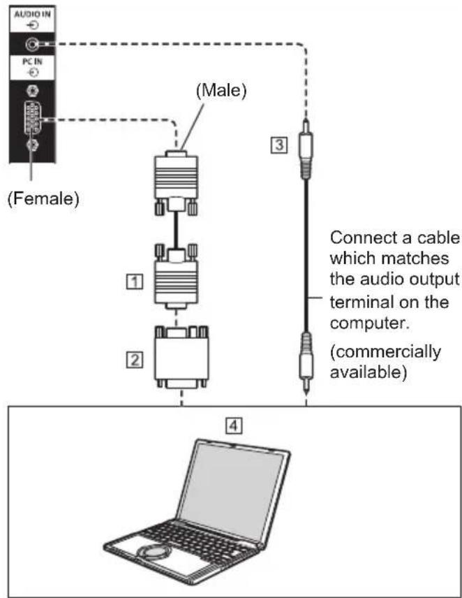
① Mini D-sub 15p cable (commercially available)
② Conversion adapter (if necessary) (commercially available)
3 Stereo mini plug (M3) cable (commercially available)
4PC
The type of computer signal that can be connected
- With regard to the typical PC input signals that are described in "Preset Signals" (see page 52), adjustment values such as for the standard picture positions and sizes have already been stored in this unit.
(Computer signals which can be input are those with a horizontal scanning frequency of 31 to 83 kHz and vertical scanning frequency of 56 to 76 Hz.)
- If signals outside the range of supported frequencies are input, normal images cannot be displayed. Note that some images may not be correctly displayed even if signals are within the range.
- If the PC screen is not displayed, check if the image signal of the PC meets "Preset Signals" (see page 52), and then change the settings. For power-saving purpose, image output may be OFF on a notebook computer. In this case, it may be set to ON with function key operation etc. of the computer. (Refer to the manual of the computer.)
Note
• Additional computer, cables and conversion adapter shown are not supplied with this set.
- If the computer being connected is not DDC2B-compatible, you will need to make setting changes to the computer at the time of connection.
- When connecting a computer equipped with a D-sub15 pin terminal or a Mac, use a commercially sold conversion adapter as necessary.
* There is no need to use an adapter for computers with DOS/V compatible Mini D-sub 15P terminal.
- Do not set the horizontal and vertical scanning frequencies for PC signals which are above or below the specified frequency range.
- For audio, the AUDIO IN terminal can be used.
Pin assignments and signal names for PC Input Terminal (Mini D-sub 15P)
| Pin No. Signal Name | |
| 1 | Red video signal input |
| 2 | Green video signal input |
| 3 | Blue video signal input |
| 4 | NC (not connected) |
| 5 | GND |
| 6 | GND for red video signal |
| 7 | GND for green video signal |
| 8 | GND for blue video signal |
| 9 | +5 V DC |
| 10 | GND (Ground) |
| 11 | NC (not connected) |
| 12 | DDC data |
| 13 | Hsync Signal input |
| 14 | Vsync Signal input |
| 15 | DDC Clock |
RS232 terminal connection
The RS232 terminal conforms to the RS-232C interface specification, so that the TV can be controlled by a computer which is connected to this terminal.
Note
• Additional computer and cables shown are not supplied with this set.
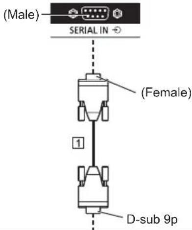
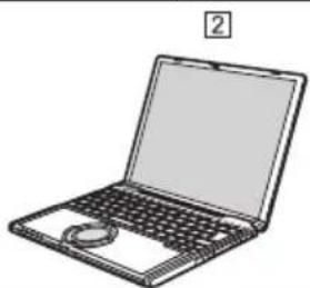
natural_image
Line drawing of a laptop computer with visible screen and keyboard (no text or symbols)① RS-232C Straight cable (commercially available)
② PC
Note
- Select the RS-232C straight cable for communication used for connecting RS232 terminal and computer according to the computer you are using.
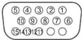
Pin assignments and signal names for SERIAL Terminal
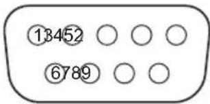
| Pin No. Signal Name | |
| 1 | NC (not connected) |
| 2 | Received data |
| 3 | Transmitted data |
| 4 | NC (not connected) |
| 5 | GND (Ground) |
| 6 | NC (not connected) |
| 7 | NC (not connected) |
| 8 | NC (not connected) |
| 9 | NC (not connected) |
These signal names are those of computer specifications.
Communication parameters
Signal level: RS-232C compliant
Synchronization method: Asynchronous
Baud rate: 9 600 bps
Parity: None
Character length: 8 bits
Stop bit: 1 bit
Flow control: None
Basic format for control data
The transmission of control data starts with a STX signal, followed by the command, the parameters, and lastly an ETX signal in that order. If there are no parameters, the colon “:” does not need to be sent.
flowchart
graph TD
    A["STX"] --> B["C1 C2 C3 F1"]
    B --> C["P2 P3 F4: P5 ETX"]
    C --> D["End"]
    E["Start"] --> B
    F["Colon"] --> C
    G["3-character command 3 bytes) "] --> B
    H["Parameter(s)"] --> C
Command
| Command Parameter Control details | ||
| PON (None) Power ON | ||
| POF | (None) Power OFF | |
| AVL | *** | VOLUME 000 - 100 |
| AMT | 0 | Audio MUTE OFF |
| 1 | Audio MUTE ON | |
| IMS | (None) Input select (toggle) | |
| TV1 | ANTENNA/CABLE IN input (TV) | |
| HM1 | HDMI IN 1 input (HDMI1) | |
| HM2 | HDMI IN 2 input (HDMI2) | |
| HM3 | HDMI IN 3 input (HDMI3) | |
| PC1 | PC IN input (PC) | |
| UD1 | USB input (USB) | |
| STV | CUP | TV Channel Up |
| CDN | TV Channel Down | |
| DAM | FULL | Full |
| NORM Normal | ||
| NATV | Native | |
| ZOOM Zoom | ||
Note
- If an incorrect command is sent, this unit will reply an "ER401" command to the computer.
- If communication has not been established for reasons such as a bad connection between the computer and TV, nothing is returned (not even ER401).
- "ER401" may be returned when a command cannot be received correctly due to interference from the surrounding environment.
Please ensure that the system or software resends the command if this occurs.
Communication interval
After getting the feedback, then you can continue the following commands.
Suggest setting a timeout for the command response. (specify 10 seconds or longer)
If multiple commands are transmitted, be sure to wait for the response for the first command to come from this unit before sending the next command.
- When sending a command which does not require parameter, a colon (:) is not needed.
- Consult your local Panasonic dealer for detail instructions on command usage.
For mode details, visit the following web site.
http://panasonic.net/cns/prodisplays/
AUDIO OUT terminal connection
Note
- Audio equipment and the cable shown are not supplied with this set.
natural_image
Illustration of a multi-compartment electronic device with front panel and buttons (no text or symbols)① Stereo audio cable (commercially available)
② Audio equipment
Antenna connection
Back of the TV
VHF/UHF Antenna
• NTSC (National Television System Committee): Analog television system
- ATSC (Advanced Television System Committee): Digital TV Standards include digital high-definition television (HDTV), standard-definition television (SDTV), data broadcasting, multi-channel surround sound audio and interactive television.
Cable
- You need to subscribe to a cable TV service to enjoy viewing their programming.
- You can enjoy high-definition programming by subscribing to a high-definition cable service.
USB terminal connection
Connect a USB memory device to the USB port.
Note
- Do not connect a USB device other than a USB memory device.
- Turn off the power of the TV when removing a USB memory device.
- If the power is turned off or the USB memory device is removed while accessing data in the USB memory device, the stored data may be destroyed. The access indicator of the USB memory device blinks during data access.
■ Supported USB memory device
| File System FAT16/32 | |
| Capacity Up to 32GB | (maximum file size 4 GB) |
Note
- Do not use a USB memory device with a security function or a write protection function.
• Multi partition is not supported. - Use a USB memory device with a shape that can be inserted in the USB port. Some USB memory devices with special shapes cannot be inserted. Do not forcibly insert a USB memory device. This may damage the connector and cause failure.
Pin assignments and signal names for USB Terminal
| Pin No. | Signal name |
| 1 | +5 V DC |
| 2 | DATA - |
| 3 | DATA + |
| 4 | GND (Ground) |
Power of up to 5 V / 2.0 A can be supplied to an external device when the picture is displayed.
Note
- If the direct connection to this unit is not possible due to the size of a stick PC, etc. use a commercially sold extension cable.
- Depending on the type of a USB memory device, it may come in contact with the periphery such as a back cover, and cannot be attached. Use a USB memory device connectable to this unit.
- When connecting the USB memory device, confirm the orientation of the plug to prevent damage to the terminal.
- When removing the USB memory device, note the following.
- When the access indicator of the connected USB memory device is blinking, it shows the TV is loading the data. Do not remove the USB memory device while blinking.
- Depending on the USB memory device, the access indicator may remain blinking even when it is not being accessed, or the device is not equipped with an access indicator function, etc. In this case, remove the USB memory device after confirming the following ①or .②
① Switch the input to an input other than [USB], and confirm that the functions that access USB memory device are finished.
② Turn the unit off.
- Do not frequently repeat connecting/disconnecting the USB memory device. Wait at least 5 seconds after connection, and then remove the USB memory device. Before reconnection, wait at least 5 seconds. A certain length of time is required so that the TV can recognise that the USB memory device is switched for connection or disconnection.
- If the power of this unit is turned off or the USB memory device is removed accidentally while accessing data, the data may not be accessed next time the USB memory device is used.
In such a case, turn the power of the main unit off and on.
Identifying Controls
Display
natural_image
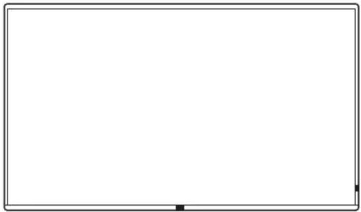
Front view of a blank rectangular screen with a small inset showing a numbered label '1' (no text or symbols on the screen itself)1 Power Indicator / Remote control sensor
The Power Indicator will light.
When the power of the unit is ON
(Power button (⊕/| (Unit): ON)
• Picture is displayed: Green
- When the unit enters the standby mode: Red or orange
When the unit enters the standby state with the following functions: Orange
- Standby state when [Power save mode] is set to [Disable]
For details of the [Power save mode] function (see page 38) - Standby state when the [Power Management] function is activated For details of the [Power Management] function (see page 38)
- Standby state when the [Setup Timer] function is being used For details of the [Setup Timer] function (see page 35)
Standby states in conditions other than the above: Red
1 External input / output terminal
Connects to video equipment, PC, etc. (see page 17)
2 Main power switch (O/I) (Unit)
Turns OFF (○) or ON (|) the main power.
Turning ON and OFF the
3 Power button (☐/|) (Unit)
When the
4 INPUT (Unit)
Selects the connected device. (see page 27)
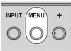
5 MENU (Unit)
Displays the menu screen. (see page 30)
6 + (Unit) / - (Unit)
Adjusts the volume. (see page 28)
On the main screen, switches settings or adjusts settings level. (see page 30)
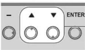
7 ▲ (Unit) / ▼(Unit)
When TV input, changes the channel.
Selects the setting item on menu screen. (see page 30)
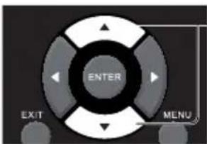
8 ENTER (Unit)
Configures the item on menu screen. (see page 30)
Note
- To output sound from the built-in speakers of the unit, be sure to set [Speaker] in the [Sound] menu to [Enable]. (see page 33)
Remote Control Transmitter
1 POWER ON button ( )
- Turns the power on (Picture is displayed) when the TV is turned off (Standby condition).
2 STANDBY button (⏻)
- Turns the power off (Standby condition) when the TV is turned on.
3 Numeric buttons (0 - 9) / ·
- Changes channel. You can also use the button when you enter numeric or dot. - Input numbers in LAN settings.
4 PICTURE
- Adjust Picture mode. (see page 32)
5 AUDIO
- Changed MTS or audio language. (see page 33)
6 VOL + / VOL -
• Adjusts sound volume level. (see page 28)
7 Navigation keys (◀◀, □▶, ▶▶)
• Used in the USB menu and HDMI CEC function.
8 ENTER / Cursor buttons

• Used to operate the menu screens. (see page 30)
9 EXIT
• Turns off the menu screens. (see page 30)
10 DISPLAY
• Displays information about the TV. (see page 28)
11 ASPECT
• Change aspect ratio. (see page 29)
12 FAVORITE
• Displays registered favorite channel list.
13 MUTE
• Sound mute on / off. (see page 28)
14 CH ∧ / V
- Changes channel.
15 INPUT
- Switches input to display on the screen. (see page 27)
16 MENU
- Press to open the OSD menu. (see page 30)
Note
- In this manual, buttons of the remote control and the unit are indicated as < >.
(Example: .)
The operation is mainly explained indicating the remote control buttons but you can also operate with the buttons on the unit when there are the same buttons.
Basic Controls
Power button (☐/|) (Unit) (Back of the unit)
Operate pointing the remote control directly at the unit's Remote Control Sensor.
Note
- Do not put an obstacle between the remote control sensor of the main unit and the remote control.
- Operate the remote control in front of the remote control sensor or from the area where the sensor can be seen.
- When directly aiming the remote control at the remote control sensor of the main unit, the distance from the front of remote control sensor should be approx. 7 m or less. Depending on the angle, the operation distance may be shorter.
- Do not subject the remote control sensor of the main unit to the direct sunlight or strong fluorescent light.
1 Connect the AC cord plug to the TV.
(see page 16)
2 Connect the plug to the socket outlet.
Note
- When disconnecting the AC cord, be absolutely sure to disconnect the AC cord plug at the socket outlet first.
- The settings may not be saved if the power plug is disconnected immediately after changing settings with on-screen menu. Disconnect the power plug after a enough period of time. Or, disconnect the power plug after turning the power off with the remote control, RS-232C control or LAN control.
3 Turn ON (1) the
4 Press the
• Power Indicator: Green (Picture is displayed.)
- When the
- When the power indicator is lit, it is not necessary to press the
■ To turn the power ON/OFF with the remote control
To turn the power on
- When the
is ON (1) (Power Indicator - red or orange), press <POWER ON button (1) then the picture will be displayed.
• Power Indicator: Green (Picture is displayed.)
To turn the power off (Standby condition)
- When the
is ON (I) (Power Indicator - green), press <STANDBY button (Q), then the power will be turned off.
• Power Indicator: Red or orange (standby) - The display turns off if the
is turned OFF (○) while the unit is ON (picture is displayed) or OFF (standby state).
Note
- After the power plug is disconnected, the power indicator may remain lit for a while. This is not a malfunction.
■ When the Unit is turned on for the first time
Following screen will be displayed.
Important
Please read carefully.
This product's power save mode has been set to enable (low power mode) before shipping. (To reduce power consumption in standby mode)
During power standby at low power mode settings:
- LAN function cannot be used.
Are you sure you want to use low power mode?
Please select "YES" if you agree with this condition.
Yes No
■ Power save mode
When this TV is turned on for the first time after being shipped from the factory, the power save mode setting screen will be displayed.
[Yes]: The TV's consumption in standby mode is reduced. However, the startup time from standby mode becomes longer.
[No]: It is reduced that startup time from standby mode. However, more power will be consumed in standby mode.
Even after being set, you can change the "Power save mode". (see page 38)
Selecting the input signal
Select the signals input to the unit.
Press or
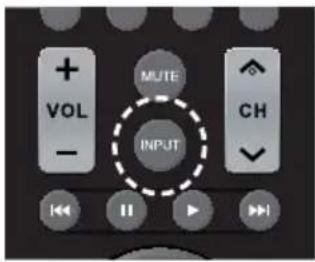
Unit
Input
TV
HDMI1
HDMI2
HDMI3
PC
USB
[TV]: Antenna terminal
[HDMI1]: HDMI IN 1 terminal, HDMI input
[HDMI2]: HDMI IN 2 terminal, HDMI input
[HDMI3]: HDMI IN 3 terminal, HDMI input
[PC]: PC Input Terminal
[USB]: USB terminal, USB input
DISPLAY
It is possible to check the channel information.
Press
Current setting status will be displayed.
1 Channel position and name
2 Channel position
3 Channel name
4 Program start / Finish time
5 Program introduction
6 Signal resolution / Signal Audio
7 Signal strength
8 Rating (Parental control)
Volume Adjustment
Press
Unit

6
- The current sound volume level is memorised even if the power is turned off.
Sound mute On / Off
It is useful when you want to mute the sound temporarily, for example, when answering the phone or door.
Press .
• 📋 appears on the screen and the sound is muted. Press again to reactivate the sound.
- It is also reactivated when the power is turned on / off or the volume level is changed.
ASPECT Controls
Press
[Normal] → [Zoom] → [Full] → [Native]
Note
- The aspect mode is memorised separately for each input terminal.
■ List of Aspect Modes
| Aspect mode | Description |
| Normal | Picture ➔ Enlarged screen Pictures are displayed with the aspect ratio of input signals. Pictures are displayed with the aspect ratio of input signals. |
| Zoom |  Pictures are displayed in full screen with the aspect ratio of input signals. Edges of the pictures may not be displayed. Pictures are displayed in full screen with the aspect ratio of input signals. Edges of the pictures may not be displayed. |
| Full |  Pictures are displayed filling the screen. Pictures are displayed filling the screen. |
| Native |  According the input signals to display the picture. Refer to “Preset Signals” (see page 52) for the applicable input signal that can be displayed. According the input signals to display the picture. Refer to “Preset Signals” (see page 52) for the applicable input signal that can be displayed. |
On-Screen Menu Displays
1 Display the menu screen.
Remote Control
Press to select.
Unit
2 Select the item.
Press to select.
Press to select.
(Example: [Picture] menu)
To display the submenu, press
3 Set.
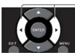
Press to set.
Press to set.
4 Exit from the menu.
Press to exit the menu.
Press
- Menu that cannot be adjusted is greyed out. Adjustable menu changes depending on signal, input and menu setting.
- The menu will differ depending on the input mode. (Example: TV input)
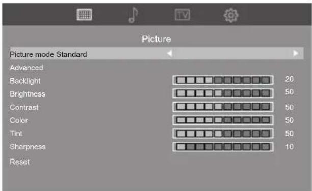
[Picture] menu
(see page 32)
[Sound] menu
(see page 33)
[TV] menu
(see page 34)
[Setup] menu
(see page 35 - 42)
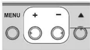
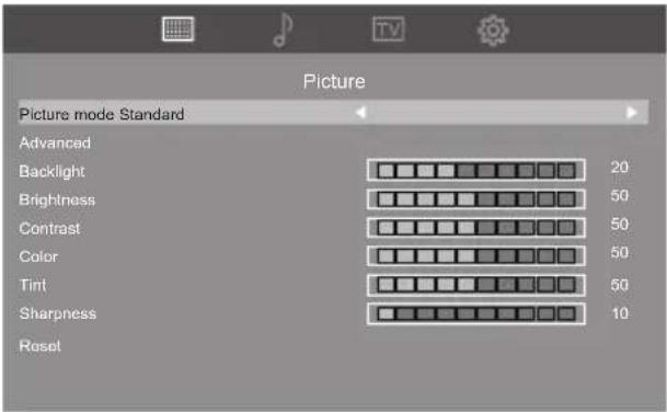
Picture Adjustments
1 Press
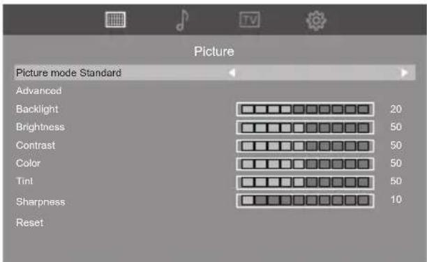
2 Select the item to adjust with <▲▼.
- Menu that cannot be adjusted is greyed out.
3 Adjust with < ◀▶.
4 Press to exit from adjust mode.
■ To return to the previous screen
Press
- Smaller the [Preset] value, red is emphasized. Larger the [Preset] value, blue is emphasized.
- When [Native] is selected, the original colour tone for the LCD panel is reproduced.
[Custom]:
The colour temperature can be set by the user.
[Noise reduction]:
Sets to reduce the video noise.
Note
- This menu is grayed out for signals other than HDMI YUV signal.
[Dynamic backlight control]:
Optimizes the backlight brightness to enhance contrast and reduce total power consumption.
[Gamma]:
Selects the gamma curve.
[HDMI RGB Signal Range]:
Switches the dynamic range depending on the input signal of the HDMI terminal.
This is enabled only for RGB signal input.
[Video(16-235)]:
When the input signal is in video range
[Full(0-255)]:
When the input signal is in full range
[Auto]:
Automatically switches the dynamic range to [Video(16-235)] or [Full(0-255)] depending on the input signal.
[Dynamic contrast]:
Automatically adjusts the contrast by determining the changes in the use of colours for images that constantly change, such as motion pictures.
- The adjustment operation may not be smooth depending on the image. In this case select Off.
Note
- This menu is grayed out for signals other than HDMI YUV signal.
[Backlight] Selects the proper brightness and density for the room.
Less ↔ More
[Brightness] Adjusts the entire brightness of the video signals.
Less ↔ More
[Contrast] Adjusts for easier viewing of dark pictures.
Less ↔ More
[Color] Adjusts colour saturation.
Less ↔ More
[Tint] Adjusts hue of skin colour.
Reddish ↔ Greenish
[Sharpness] Adjusts picture sharpness.
Less ↔ More
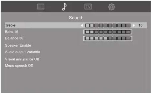
Sound Adjustment
1 Press
- Set the date and time correctly. (see page 35)
- Check periodically if the set date and time are correct. [Setup Timer] submenu screen
① Select the program number to set the timer and press
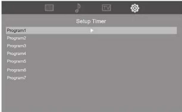
② Set the details of the timer.
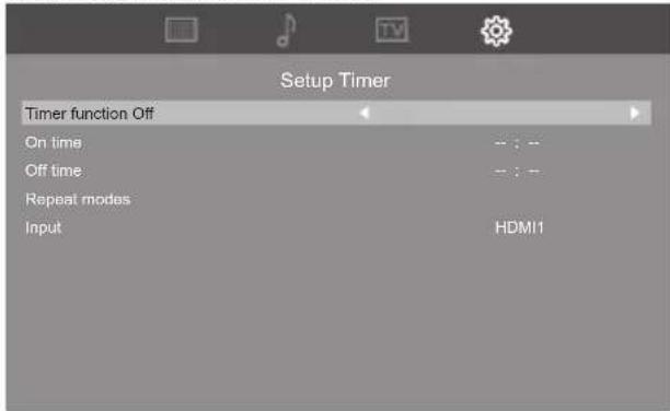
[Timer function]
[On]:
The timer setting is enabled.
[Off]:
The timer setting is disabled.
■ [On time]
Sets the time to turn the power on.
■ [Off time]
Sets the time to turn the power off.
■ [Repeat modes]
Select [Repeat modes] and press
Select the day and press
- When [On time] or [Off time] is not set, the display shows [--:--] (not set).
- When [On time] and [Off time] are set simultaneously, or when only [On time] is set, the power is turned on at the set time.
- [On time] and [Off time] can be set from 00:00 to 23:59 on the same date. [Off time] cannot be set before the time set for [On time].
Network settings
Selects the method with which to control the TV from the computer.
[Network settings] submenu will be displayed.
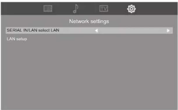
■ [SERIAL IN/LAN select]
RS-232C or LAN function is enable. To control the TV via RS-232C, set [SERIAL IN/LAN select] to [SERIAL IN].
Note
- You cannot use RS-232C and LAN control simultaneously.
[LAN setup]
Controls via LAN using the LAN terminal.
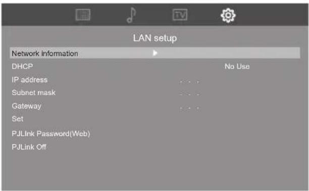
[Network information]
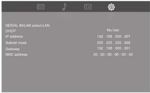
[DHCP], [IP address], [Subnet mask], [Gateway]
①Press< → no set [Use] / [No Use] of [DHCP].
When [No Use] is selected, IP address and other settings can be set manually.
[DHCP]:
[Use]: Use Dynamic IP address.
[No Use]: Use Static IP address, Subnet mask, and Gateway.
[IP address]:
Enter IP address when [DHCP] is [No Use].
[Subnet mask]:
Enter Subnet mask when [DHCP] is [No Use].
[Gateway]:
Enter Gateway address when [DHCP] is [No Use].
Note
- When [DHCP] is set to [Use], others will be displayed in grey.
Entering numbers
②Select[Set] and press .
Save the current network Setup.
Note
- To use a DHCP server, make sure the DHCP server is started.
- Contact your network administrator for details on [IP address], [Subnet mask] and [Gateway].
• Shipping condition [DHCP]: [Use]
[PJLink Password(Web)]
Selecting this item allows you to set the PJLink password from the web page of this unit. For details, refer to "Using Network Function". (see page 43)
[PJLink]
Set this item to [On] when using the PJLink control. For details, refer to "Using Network Function". (see page 43)
Note
- PJLink control cannot be performed if [PJLInk Password(Web)] is not set at the time of purchase or after [All reset].
HDMI-CEC control
Set for HDMI-CEC function.
For details of HDMI-CEC function, refer to "Using HDMI-CEC function". (see page 51)
[On]
When set to [On], the TV will automatically switch to the appropriate HDMI input whenever an HDMI connected equipment is initially turned on and the Play mode is selected.
[Off]
Disables HDMI-CEC control.
Note
- The HDMI CEC feature of connected HDMI CEC-compatible device must be turned on.
EDID select
The menu is displayed in HDMI1, HDMI2 and HDMI 3 inputs.
EDID data of each HDMI terminal is switched.
[EDID select] - submenu screen
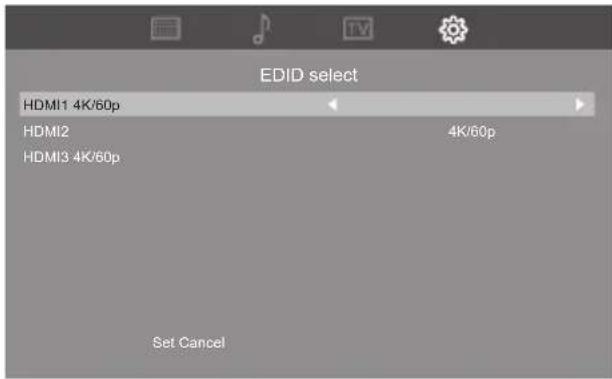
[4K/60p]
Sets EDID compatible with 4K video signals (Max. 4096 x 2160 dots, Max. vertical operation frequency 60 Hz).
[4K/30p]
Sets EDID compatible with 4K video signals (Max. 4096 x 2160 dots, Max. vertical operation frequency 30 Hz).
[Set]:
The specified contents are set. Restart the unit to apply the settings.
[Cancel]:
The specified contents are canceled.
Note
- The settings are not applied until the unit is restarted after [Set] is selected.
Position
Adjusts the position.
[Position] - submenu screen
Note
- In some cases, noise appears outside the area picture is displayed, but it is not a malfunction of the image.
• It is only available for PC input.
[Position] - submenu screen
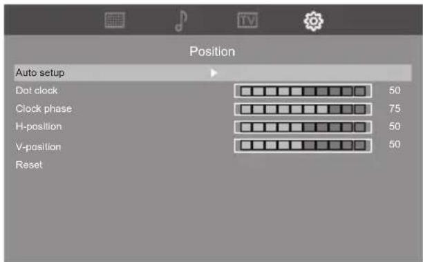
[Auto setup]
Sets the operational mode of the automatic position adjustment.
Note
- [Auto setup] may not work when a cropped or dark image is input. In such case, switch to a bright image with borders and other objects are clearly shown, and then try [Auto setup] again.
[Dot clock]
Periodic striped pattern interference (noise) may occur when a striped pattern is displayed. If this happens, adjust so that any such noise is minimized.
[Clock phase]
Adjusts sampling clock for applicable video.
Useful when small characters appear with low contrast and/or there are flickers at corners.
When using the adjustment pattern, make adjustments so that no horizontal stripe noise appears in it.
- It should be made only after [Dot clock] has been correctly set.
■ [H-position]
Adjusts the horizontal position of the image.
![PANASONIC TH-65CQE2U - ■ [H-position] - 1](/content/2026/05/1044874/images/cb77adfdf2c5136c72cc04339e9327047b078d50297324c51e957431880d1c09.jpg)
natural_image
Two diagrams showing circular shapes with dashed arrows indicating transformation or alignment (no text or symbols)[V-position]
Adjusts the vertical position of the image.
![PANASONIC TH-65CQE2U - [V-position] - 1](/content/2026/05/1044874/images/ffd7b930da7e048ad728d501c7898606964c9b311425b65f7ebbc194c5e26e22.jpg)
natural_image
Two diagrams showing circular and curved shapes with arrows indicating direction, no text or symbols present.[Reset]
Resets the values of [Position] items to the factory default settings.
Note
- In some cases, noise appears outside the area picture is displayed, but it is not a malfunction.
- It is only available for PC input.
- In the case that [Auto setup] cannot work well, [Auto setup] may work well to execute [Reset] before [Auto setup].
Power save mode
When this function is set to [Disable], the power can be turned on by LAN control in standby mode, but the power consumption is increased in standby mode.
When this function is set to [Enable], the power cannot be turned on by LAN control in standby mode, but the power consumption is reduced in standby mode.
(Serial control enables the power to be turned on in standby mode regardless of [Disable] or [Enable] selected in the setting.)
Power Management
This function turns the power off (standby) when video signals are not detected with HDMI or PC input, and turns the power on when video signals are detected.
Note
- If the power is turned off (standby) using the remote control, this function is not activated.
- Video signals can be detected only with input terminals with which video signals are not detected at power-on. When the unit enters the standby state with this function, the power indicator lights in orange.
e.g. When video signals are not detected with HDMI1 input:
Power off (standby), Power indicator lights in orange.
When video signals are detected with HDMI1 input later:
Power on, Power indicator lights in green.
Auto play(USB)
Sets the type of file to be automatically played from a USB memory device.
[Disable]
Disables the Auto playback function.
[Photo]
Photos in a USB memory device can be played automatically. (*.jpg file only)
[Video]
Video in a USB memory device can be played automatically. (*.mp4 file only)
Note
- Photos and video cannot be played automatically at the same time. (see page 48)
Button lock
Disables the TV buttons.
[Unlocked]
All the buttons on main unit can be used.
[Lock all]
All the buttons on main unit can not be used.
■ [Lock except volume]
Disabling all button operations on main unit except < + > and < - >.
■ [Lock except power]
Disabling all button operations on main unit except <Power button (0)
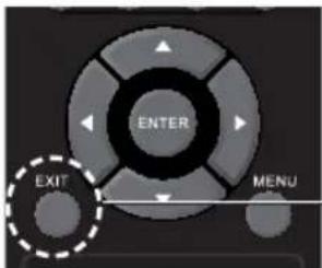
To cancel [Button lock]
- Press
![PANASONIC TH-65CQE2U - To cancel [Button lock] - 1](/content/2026/05/1044874/images/cfa14f9be2bfd067d244577064109986f938c0791542375ffb8345542d8d17e2.jpg)
- You can also disconnect the power plug from socket outlet and then reconnecting the power plug while pressing the
RC control lock
Disables the remote control buttons.
[Unlocked]
All the buttons on your remote control can be used.
[Lock all]
All the buttons on your remote control can not be used.
■ [Lock except volume]
Disabling all button operations on your remote control except
■ [Lock except power]
Disabling all button operations on your remote control except
To cancel [RC control lock]
- Press
![PANASONIC TH-65CQE2U - To cancel [RC control lock] - 1](/content/2026/05/1044874/images/d40f0390a4ecef497e1adb02c77e47b6a6a6ed5f67e28192028252366a2feee3.jpg)
- You can also disconnect the power plug from socket outlet and then reconnecting the power plug while pressing the
Front indicator light
Enables / Disables the power LED.
Information
Displays the display information.
Parental control
Sets to filter programs not suitable for children's viewing. [Parental control] - submenu screen
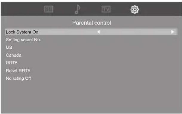
■ [Lock System]
Set this item to [On] to perform [Parental control]. When changing each item of [Parental control], select this [Lock System] item and press
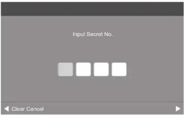
■ [Setting secret No.]
It allows to use a secret number to protect certain settings from being accidentally changed. "0000" is set as the default value.
Note
- Make a note of your password in case you forget it. (If you have forgotten your password, consult your local dealer.)
[US]
It will wake up "US rating list". The list has two rating systems for MPAA (Movie ratings) and TV (TV Parental Guidelines).
Movie ratings are used for original movies rated by Motion Picture Association of America (MPAA) as watched on cable TV and not edited for television. TheV-CHIP can also be set to block MPAA-rated movies.
The TV Parental Guidelines work in conjunction with the V-CHIP to help parents screen out inappropriate television shows from their children.
[MPAA]: (Voluntary movie rating system)
Sets parental control on movie ratings.
| G General | audiences. All ages admitted. |
| PG Parental | guidance suggested. Some material may not be suitable for children. |
| PG-13 Parents strongly cautioned. Some material may be inappropriate for children under 13. | |
| R Restricted. Under 17 requires accompanying parent or adult guardian (age varies in some jurisdictions). | |
| NC-17 No | one 17 and under admitted. |
| X It is an older rating that is unified with NC-17 but may be encoded in the data of older movies. | |
[TV guidelines]:
- Suggestedage
| None Do not set parental controls. | |
| TV-Y All children. | |
| TV-Y7 Directed to older children. | |
| TV-G | General audience. |
| TV-PG | Parental Guidance suggested. |
| TV-14 | Parents strongly cautioned. |
| TV-MA | Mature audience only. |
2.Content
| All | All contents. |
| FV | Fantasy violence. |
| L | Adult language. |
| S Sexual situation. | |
| V Violence | |
| D Sexually suggestive dialog. | |
| Rating | Content | ||||||
| All | FV | L | S | V | D | ||
| Suggested age | TV-Y | Yes | No | No | No | No | No |
| TV-Y7 | Yes | Yes | No | No | No | No | |
| TV-G | Yes | No | No | No | No | No | |
| TV-PG | Yes | No | Yes | Yes | Yes | Yes | |
| TV-14 | Yes | No | Yes | Yes | Yes | Yes | |
| TV-MA | Yes | No | Yes | Yes | Yes | No | |
[Canada]
The TV rating systems in Canada are based on the Canadian Radio-Television and Telecommunications Commission (CRTC) policy on violence in television programming.
It will wake up "Canada rating list". The list has two rating settings for Can. English ratings and Can. French ratings.
While violence is the most important content element to be rated, the structure developed takes into consideration other program content like language, nudity, sexuality and mature themes.
When setting the V-CHIP on the Canadian system you can choose either the Canadian English ratings or the Canadian French ratings.
[Can. English ratings]:
Sets parental control on Can. English ratings.
| C(Children) | Intended for younger children under the age of 8 years. Pays careful attention to themes that could threaten their sense of security and well-being. |
| C8+(Children over 8 years old) | Contains no portrayal of violence as the preferred, acceptable, or only way to resolve conflict; nor encourage children to imitate dangerous acts which they may see on the screen. |
| G(General) | Considered acceptable for all age groups. Appropriate viewing for the entire family, contains very little violence, physical, verbal or emotional. |
| PG(Parental Guidance) | Intended for a general audience, but may not be suitable for younger children (under the age of 8) because it could contain controversial themes or issues. |
| 14+(Over 14 years) | Could contain themes where violence is one of the dominant elements of the storyline, but it must be integral to the development of plot or character. Language usage could be profane and nudity present within the context of the theme. |
| 18+(Adults) | Intended for viewers 18 years and older and might contain depictions of violence, which while related to the development of plot, character or themes, are intended for adult viewing. Could contain graphic language and portrayals of sex and nudity. |
[Can.French ratings]:
Sets parental control on Can.French ratings.
| G(General) | All ages and children, contains minimal direct violence, but may be integrated into the plot in a humorous or unrealistic manner. |
| 8ans+(General but inad-visible for young children) | May be viewed by a wide public audience, but could contain scenes disturbing to children under 8 who cannot distinguish between imaginary and real situations. Recommended for viewing with parent. |
| 13ans+(Over 13 years) | Could contain scenes of frequent violent scenes and therefore recommended for viewing with parent. |
| 16ans+(Over 16 years) | Could contain frequent violent scenes and intense violence. |
| 18ans+(Over 18 years) | Only for adult viewing. Could contain frequent violent scenes and extreme violence. |
[RRT5]
Sets the RRT5(Rating Region Table 5) setting.
[Reset RRT5]
Resets the RRT5 setting.
[No rating]
Blocks programs without rating.
Closed caption
The television include a built-in decoder that is capable of providing a text display of the audio.
The program being viewed must be transmitting the Closed caption (CC) information.
Note
- It is only available for TV and AV input.
■ [Caption display]
[CC off]: To disable Closed caption.
[CC on]: To display Closed captions.
[CC on when mute]: To display Closed captions when the audio is muted.
[Analog CC]
[CC1 - CC4]: Information related to pictures.
[Text1 - Text4]: Textual information.
[Digital CC]
The Digital Closed caption menu lets you configure the way you choose to view the digital captioning.
■ [Caption setup]
[Font] / [Size] / [Edge effect] / [Edge color] / [Text color] / [Background color]
[Text opacity]: How "see through" the captions are.
[BG opacity]: How "see through" the background of the captions is.
Note
• It is only available for Digital TV.
All reset
It is possible to reset the data to the factory settings.
Using Network Function
This unit has a network function and you can control the TV connected to the network using your computer.
Necessary environment for computers to be connected
First of all, confirm your computer whether it has a wired LAN.
Before connecting the TV to the computer, be sure to check the following settings.
Check 1: About LAN cable
- Connect the cable properly.
- Use LAN cable that is compatible with category 5e or above.
Check 2: Wired LAN settings
Computer with a built-in wired LAN function
- Switch on the wired LAN.
- Check that your wired LAN adapter is recognized properly and it is switched on.
• Install the wired LAN adapter driver beforehand.
Computer without a built-in wired LAN function
For details on how to install the driver, refer to the instructions accompanying the wired LAN adapter.
Example of network connection
Note
- When [Power save mode] is set to [Enable], the control is disabled in the standby mode.
- To use the network function, set each item in [Network settings] and make sure to select [LAN]. (see page 36)
- You cannot use RS-232C and LAN control simultaneously.
■ LAN Terminal connection
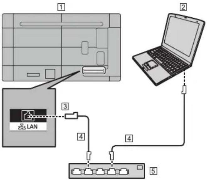
flowchart
graph TD
    A["1: LAN"] --> B["2: Laptop"]
    B --> C["3: LAN"]
    C --> D["4: LAN"]
    D --> E["5: Server Port"]
    style A fill:#f9f,stroke:#333
    style B fill:#ccf,stroke:#333
    style C fill:#cfc,stroke:#333
    style D fill:#fcc,stroke:#333
    style E fill:#cff,stroke:#333
① TV (Back of the unit)
② PC
③ LAN terminal
4 LAN cable (commercially available)
⑤ Hub or broadband router
Note
- For LAN cable, use shielded cable, otherwise picture noise may be caused.
• Make sure the broadband router or hub supports 10BASE-T / 100BASE-TX. - Touching the LAN Terminal with a statically charged hand (body) may cause damage to the device due to its discharge.
Do not touch the LAN Terminal or the metal part of the LAN cable. - For instructions on connection, consult your network administrator.
Settings to connect to a LAN
[Important]
The network environment when controlling via LAN is required to be physically isolated from the outside network or not illegally connected / controlled by unknown equipment with the Firewall.
Set the TV's IP address and subnet mask to match the settings of your LAN.
These settings can be made on either the TV or a computer connected to the TV.
The settings depend on the configuration of your LAN. For instructions on connection, consult your network administrator.
To set on the TV
Set [SERIAL IN/LAN select] of [Network settings] on the [Setup] menu to [LAN], and then set the [LAN setup] options. (see page 36)
After setting each item, select [Set] and press
■ Network information
Displays LAN setting information. (see page 36)
Preparation for PJLink control
To perform LAN control (PJLink), connect to the network for the first time after purchase or after [All reset], display the web page of this unit on the PC browser, and be sure to set the password.
The setting on the web page is effective for 3 minutes after selecting [Network settings] - [LAN setup] - [PJLInk Password(Web)].
■ Restriction to access the web page
The user name and password are necessary to access the web page.
User name: dispadmin (fixed)
Initial password: @Panasonic
It is also necessary to set this password for the first time after purchase or after [All reset].
(1) When newly setting a PJLink password
1 Connect this unit and PC to the network.
(see page 43)
2 Select [Network settings] - [LAN setup] - [PJLInk Password(Web)].
(see page 37)
3 Start up the web browser on the PC.
4 Enter the IP address that has been set for [LAN setup] of this unit into the address bar on the web browser.
5 Enter the password to access this web page and the PJLink password (enter the same password twice, which is the password to be set and password for confirmation) and click [Apply].
Panasonic CQ2 Web Server
Model Name: Panasonic CQ2
(2) When changing the password to access this web page and the PJLink password
Connect this unit and PC to the network in the same way as in (1), and configure the setting on the browser. Enter each of current passwords and set new passwords (enter the same password twice, which is the new password and password for confirmation).
Panasonic CQ2 Web Server
Model Name: Panasonic CQ2
Note
- The web page is displayed only in English.
Password to restrict the access to the web page
Use a password to restrict the access to the web page
Change the password first.
- When [All reset] is executed, the password returns to the original value.
- The number of characters that can be used for a password is 8 characters or more and 16 characters or less.
- The following are recommendations when changing the password.
Include at least three types from the following four types of characters.
1) Alphabet uppercase character (A to Z)
2) Alphabet lowercase character (a to z)
3) Number (0 to 9)
4) Special character (\~!@#\$%&*()_+|{{}}<>./?')
PJLink security authentication
Use a password for PJLink security authentication.
Change the password first.
- [All reset] settings will restore the password to the factory default.
- The maximum number of characters that can be used for a password is 32 characters.
- Recommended password
Number of characters: 8 to 32
Include at least 3 types of character from the following.
1) Alphabet uppercase character (A-Z)
2) Alphabet lowercase character (a-z)
3) Number (0-9)
4) Special character (\~!@#\$%&*()_+|{{}}<>./?')
When using without authentication, leave the password blank.
Note
- It is recommended that do not set the same password as the current password or the same value as the factory setting as the New password.
- For PJLink specifications, visit the Japan Business Machine and Information System Industries Association (JBMIA) website:
http://pjlink.jbmia.or.jp/english/index.html - No member of the Panasonic Corporation or its affiliate companies will ever ask directly for your passwordnew
Never divulge your password should you ever receive such a request.
PJLink protocol
The unit's Network function is compatible with PJLink Class 1. The following operations can be performed from a computer when PJLink protocol is used.
- Setting the Display
• Querying the Display status
Supported commands
The commands to control the unit with PJLink protocol are as follows.
| Command Control | |
| POWR Power control0: Standby1: Power On | |
| POWR ? Power status query0: Standby1: Power On | |
| INPT Input switch* Refer to INST? parameters. | |
| INPT ? Input switch query* Refer to INST? parameters. | |
| AVMT Shutter control10: Picture On(picture mute deactivated)11: Picture Off(picture on mute)20:AudioOn(audio mute deactivated)21:AudioOff(audio on mute)30: Shutter mode Off(picture and audio mute deactivated)31: Shutter mode On(picture and audio on mute) | |
| AVMT ? Shutter control query11: Picture Off (picture on mute)21: Audio Off (audio on mute)30: Shutter mode Off(picture and audio mute deactivated)31: Shutter mode On(picture and audio on mute) | |
| ERST ? Error status queryFirst byte: 0Second byte: 0Third byte: Temperature. 0, 1, or 2.Meaning of 0, 1 or 2.0: Error is not detected,1: Warning2: ErrorFourth byte: 0Fifth byte: 0Sixth byte: 0 | |
| INST ? Input switch list query11: PC IN input (PC)31: HDMI IN 1 input (HDMI1)32: HDMI IN 2 input (HDMI2)33: HDMI IN 3 input (HDMI3)41: USB input (USB)51: ANTENNA/CABLE IN input (TV) | |
| NAME ? Display name queryReturns “55CQ2U”.(Example: 55-inch CQ2U model) | |
| INF1 ? Manufacturer name queryReturns “Panasonic”. | |
| INF2 ? Model name queryReturns “55CQ2U”.(Example: 55-inch CQ2U model) | |
| INFO ? Other information queryReturns version number. | |
| CLSS ? Class information queryReturns “1”. |
Note
Refer to the following table for error responses during communication.
| Error message |
| “ERR1”: Undefined control command |
| “ERR2”: Out of parameter range |
| “ERR3”: Busy status or reception invalid period |
| “ERR4”: Display failure |
Multi Monitoring & Control Software
This unit supports the early warning software “Multi Monitoring & Control Software” which monitors and controls devices (projectors or displays) connected to an intranet, and detects signs of abnormality of such devices that may arise in future.
As for the early warning function, the maximum number of devices that can be registered to monitor differs according to the type of license.
Up to 2 048 devices can be registered for free for a maximum of 90 days after the installation to the computer has completed.
- For more details, visit the following web site.
https://panasonic.net/cns/prodisplays/ - About early warning function, visit the following web site.
https://panasonic.net/cns/prodisplays/pass/
Using "USB media file playback function"
It allows you to enjoy photo, music or video recorded on a USB memory device. You can also play Music file during Photo file display.
For information on USB memory device, see page 23.
■ Supported formats
The unit's Media Player supports the formats below. Save immediately below root in USB memory.
Still pictures
| Codec Extension Format | Colour space Size | ||
| JPEG jpg/jpeg Baseline YUV, RGB, Max 15360 x 8640 |
Motion pictures (Motion picture files without audio cannot be played back.)
| Media type | Extension | Container | Video | ||||
| Codec | Maximum resolution | Maximum frame rate | Maximum bit rate | Profile | |||
| mp4 | MP4 | HEVC/H.265 | 4096x2176 | 60 | 100 M | Main/Main10Profile, High Tier @ Level 5.1 | |
| mp4 | MP4 | H.264 | 4096x2160 | 60 | 135 M | Main Profile and High Profile @ Level5.0 | |
| mp4 | MP4 | MPEG4 | 1920x1080 | 30 | 40 M | Simple Profile, Advanced Simple and Profile@Level 5 GMC is not supported | |
| mpg | MPEG | MPEG1 | 1920x1080 | 30 | 20 M | Main Profile | |
| mpg | MPEG | MPEG2 | 1920x1080 | 30 | 20 M | Main Profile | |
| mpg | MPEG | MPEG4 | 1920x1080 | 30 | 40 M | Simple Profile, Advanced Simple and Profile@Level 5 GMC is not supported | |
| avi | AVI | MPEG2 | 1920x1080 | 30 | 20 M | MP@HL | |
| avi | AVI | MPEG4 | 1920x1080 | 30 | 40 M | Simple Profile, Advanced Simple and Profile@Level 5 GMC is not supported | |
| avi | AVI | H.264 | 4096x2160 | 60 | 135 M | Main Profile and High Profile @ Level5.0 | |
| avi | Motion JPEG | JPEG | 640x480 | 10 M | |||
| avi | Motion JPEG | JPEG | 640x480 | 10 M | |||
| Audio | |||
| Codec | Sampling rate | Bit rate | |
| MP3 | MPEG-1 Layer2 | 16 KHz – 48 KHz | 8 Kbps – 384 Kbps |
| MPEG-1 Layer3 | 16 KHz – 48 KHz | 8 Kbps – 320 Kbps | |
| MPEG-2 Layer3 | 16 KHz – 48 KHz | 8 Kbps – 320 Kbps | |
| AC3 | 32 KHz, 44.1 KHz, 48 KHz | 32 Kbps – 640 Kbps | |
| LPCM | 8 KHz – 48 KHz | 64 Kbps – 1.5 Mbps | |
| ADPCM | 8 KHz – 48 KHz | 384 Kbps | |
| Dolby Digital Plus | 32 KHz, 44.1 KHz, 48 KHz | 32 Kbps – 6 Mbps | |
Music files
| Extension | Container | Codec | Sampling rate | Bit rate |
| mp3 | MP3 | MPEG-1 Layer2 | 16KHz – 48KHz | 8Kbps – 384Kbps |
| MPEG-1 Layer3 | 8Kbps – 320Kbps | |||
| MPEG-2 Layer3 |
Note
- Some files may not be played back even if they are in the above supported formats.
- If unsupported files are stored in a USB memory, operation may become slower.
Play file
Note
- Files are displayed/played according to the order you copy them to a USB memory device. Copy files to a USB memory device according to the order you want to play.
- You can have photo or video files play automatically when a USB memory device is connected or the power is turned on. (see page 48)
■ Select the media to be played
1. Insert the USB memory device for Media Player to the USB terminal on the side of the TV.
Note
- Depending on the type of a USB memory device, it may come in contact with the periphery such as a back cover, and cannot be attached. Use a USB memory device connectable to this unit.
- Change INPUT to [USB].
- Select the media to be played with the cursor buttons <◀/▶>, and press
.
■ Playing files
- Displays the file to be played.
Select the folder with the cursor buttons <▲▼> and press
- Select the file you want to play, and press
.
The file is selected.
Multiple files can be selected. You can also select files in different folders.
- Press
The selected files are played.
Note
• The played aspect mode is [Normal].
- If you press
- Select [Return] folder to return to the root folder, select [Up folder] folder to return to the next higher folder.
- The volume can be adjusted with the
• For operations during play, see page 49, 50.
■ To stop playing
Press
Auto playback
Photos or video in a USB memory device can be played automatically. (MAX 30 files)
■ Preparations
Prepare the files. Name the file to be played "001-030" such as "001.jpg" - "030.jpg".
- Creates a folder named "AUTO_PLAYBACK" in the root folder of a USB memory device and copy the files to be automatically played to the folder.
Select the type of file.
- Press
- Select [Auto play(USB)] with the cursor buttons <▲/▼.
- Select the type of file with the cursor buttons <◀/▶>.
■ Auto playback of files
Connect a USB memory device (see page 23) and turn on the TV power.
Auto play starts.
You can connect a USB memory device (see page 23) after turning on the TV power.
Auto play starts.
Note
- Photos and video cannot be played automatically at the same time.
- Auto play repeatedly plays all photo or video files in the "AUTO_PLAYBACK" folder.
- When motion pictures are played back in a row, a black screen is inserted between motion pictures for 1 to 2 seconds.
- During auto playback, only the button operations of
/ and are enabled.
■ To stop auto playing
Press
Playing the pictures
1 Press <◀▶ to select the media to be played, and press .
2 Press < ▲ ▼> to select the file you want to play.
▶ : To play the selected file
ENTER : Selected the file. (Multiple files can be selected.)
EXIT : To return the media type select page.
3 Press ▷
The selected picture will be displayed on the full screen.
Operation bar
Press
Use <◀/▶> to select the following operations, and press
[PLAY/PAUSE] To play the image slideshow. To pause the playing image.
[Previous] To go to previous image.
[Next] To go to next image.
[STOP] To stop the playing image slideshow.
[Repeat all] / [Repeat all] -
[Repeat none] / Files in the folder or all selected files (select files and create a play list) are played repeatedly.
[Repeat none] -
After starting playing the files selected in the menu, each file in the same folder is played once in order until the last one.
[Repeat 1] -
The one file selected or checked in the menu is repeatedly played.
[Random On] / When [Random On] is selected, all files are repeatedly played at random.
[Music Off] / Setting to [Music On], the photo and music files in the same folder are played at the same time.
[Playlist] Show Playlist.
[Info.] Show the file information.
[Rotate] Rotate the image 90 degrees (Clockwise) clockwise temporarily.
[Rotate] Rotate the image 90 degrees Anti-
(Counter- clockwise temporarily.
Clockwise)
[Zoom in] To zoom-in the image.
[Zoom out] To zoom-out the image.
[Move] Select view area in zoomed.
[Interval] Select Slideshow time.
Playing the music / video
1 Press <◀▶ to select the media to be played, and press .
2 Press < ▲ ▼> to select the file you want to play.
▶ : To play the selected file
ENTER : Selected the file. (Multiple files can be selected.)
EXIT : To return the media type select page.
3 Press ▷
The selected video will be displayed on the full screen.
Note
- The music icon is displayed on the screen for music playback.
Operation bar
Press
Use <◀/▶> to select the following operations, and press
[PLAY/PAUSE] To play the music / video. To pause the playing imag
[FB] To play the file fast backward. FB2X / FB4X / FB8X / FB16X / (motion picture only) FB32X
[FF] To play the file fast forward. FF2X / FF4X / FF8X / FF16X / (motion picture only) FF32X
| [Previous] | To go to previous the file. When playing video, press once to play from the beginning. |
| [Next] | To go to next file. |
| [STOP] | To stop the playing file. |
| [Repeat all] / [Repeat none] / [Repeat 1] | [Repeat all] - Files in the folder or all selected files (select files and create a play list) are played repeatedly. [Repeat none] - After starting playing the files selected in the menu, each file in the same folder is played once in order until the last one. [Repeat 1] - The one file selected or checked in the menu is repeatedly played. |
| [Random On] | When [Random On] is selected, all files are repeatedly played at random. |
| [Random Off] | |
| [Set A] / [Set B] / [None] | [Set A] - Set the interval of the start point. [Set B] - Set the interval of the end point. |
| [Playlist] | Show Playlist. |
| [Info.] | Show the file information. |
You can also operate the file by using the navigation keys <|◀, ||▶, ▶▶> and the cursor buttons < ◀▶> on the remote control.
Using HDMI-CEC function
The HDMI-CEC function enables the remote control of this unit alone to operate the basics of HDMI-CEC compatible devices by the interlocking control between this unit and such devices. Also, this function enables the remote control (or main unit's buttons) of a HDMI-CEC compatible device alone to turn on/off this unit and switch input.
Connection
Connect the HDMI-CEC compatible device to HDMI IN 1, HDMI IN 2 or HDMI IN 3 terminal.
① HDMI cable (commercially available)
② DVD Recorder / DVD Player, Blu-ray Recorder / Blu-ray Player
Setting
① Make the setting on the connected device (HDMI-CEC compatible device) so this function can operate.
② Set [HDMI-CEC control] to [On]. (see page 37)
③ Turn on all the devices, and turn this unit off and on. Then check if images can be seen correctly with HDMI1, HDMI2 or HDMI3 input.
This unit can display the video signals shown in the table below.
- The contents of HDMI signal in the Plug and Play-supported signal column are as follows.
1: 4K/60p, 2: 4K/30p
| Corresponding signal | Resolution (Dot) | Scanning frequency | Dot clock frequency (MHz) | Format*2 | Plug and Play-supported signal*4 | |||
| Horizontal (kHz) | Vertical (Hz) | HDMI | PC | |||||
| EDID 1 | EDID 2 | |||||||
| 480/60i 720 (1 440) | x 480i *1 | 15.73 59 | .94 27.00 H | ○ ○ | — | |||
| 576/50i 720 (1 440) | x 576i *1 | 15.63 50 | .00 27.00 H | ○ ○ | — | |||
| 480/60p 720 x 480 | 31.47 59.94 27.00 H | ○ ○ | — | |||||
| 576/50p 720 x 576 | 31.25 50.00 27.00 H | ○ ○ | — | |||||
| 720/60p 1 280 x 720 | 45.00 60.00 74.25 | H ○ ○ | — | |||||
| 720/50p 1 280 x 720 | 37.50 50.00 74.25 | H ○ ○ | — | |||||
| 1080/60i 1 920 x 1 | 080i 33.75 60.00 74. | 25 H ○ ○ | — | |||||
| 1080/50i 1 920 x 1 | 080i 28.13 50.00 74. | 25 H ○ ○ | — | |||||
| 1080/24p 1 920 x 1 | 080 27.00 24.00 74. | 25 H ○ ○ | — | |||||
| 1080/25p 1 920 x 1 | 080 28.13 25.00 74. | 25 H ○ ○ | — | |||||
| 1080/30p 1 920 x 1 | 080 33.75 30.00 74. | 25 H ○ ○ | — | |||||
| 1080/60p | 1 920 x 1 080 | 67.50 | 60.00 | 148.50 | H | ○ | ○ | — |
| 1080/50p | 1 920 x 1 080 | 56.25 | 50.00 | 148.50 | H | ○ | ○ | — |
| 3840 x 2160/24p | 3 840 x 2 160 | 54.00 | 24.00 | 297.00 | H | ○ | ○ | — |
| 3840 x 2160/25p | 3 840 x 2 160 | 56.25 | 25.00 | 297.00 | H | ○ | ○ | — |
| 3840 x 2160/30p | 3 840 x 2 160 | 67.50 | 30.00 | 297.00 | H | ○ | ○ | — |
| 3840 x 2160/60p | 3 840 x 2 160 | 135.00 | 60.00 | 594.00 | H | ○ | — | — |
| 3840 x 2160/50p | 3 840 x 2 160 | 112.50 | 50.00 | 594.00 | H | ○ | — | — |
| 4096 x 2160/24p | 4 096 x 2 160 | 54.00 | 24.00 | 297.00 | H | ○ | ○ | — |
| 4096 x 2160/25p | 4 096 x 2 160 | 56.25 | 25.00 | 297.00 | H | ○ | ○ | — |
| 4096 x 2160/30p | 4 096 x 2 160 | 67.50 | 30.00 | 297.00 | H | ○ | ○ | — |
| 4096 x 2160/60p | 4 096 x 2 160 | 135.00 | 60.00 | 594.00 | H | ○ | — | — |
| 4096 x 2160/50p | 4 096 x 2 160 | 112.50 | 50.00 | 594.00 | H | ○ | — | — |
| 640 x 480/60 | 640 x 480 | 31.47 | 59.94 | 25.18 | R/H | ○ | ○ | ○ |
| 800 x 600/60 | 800 x 600 | 37.88 | 60.32 | 40.00 | R/H | ○ | ○ | ○ |
| 1024 x 768/60 | 1 024 x 768 | 48.36 | 60.00 | 65.00 | R/H | ○ | ○ | ○ |
| 1280 x 720/60 | 1 280 x 720 | 45.00 | 60.00 | 74.25 | R/H | ○ | ○ | ○ |
| 1280 x 800/60 | 1 280 x 800 | 49.70 | 59.81 | 83.50 | R/H | ○ | ○ | ○ |
| 1280 x 960/60 | 1 280 x 960 | 60.00 | 60.00 | 108.00 | H | ○ | ○ | — |
| 1280 x 1024/60 | 1 280 x 1 024 | 63.98 | 60.02 | 108.00 | R/H | ○ | ○ | ○ |
| 1280 x 1024/75 | 1 280 x 1 024 | 79.98 | 75.02 | 135.00 | R/H | ○ | ○ | ○ |
| 1360 x 768/60 | 1 360 x 768 | 47.71 | 60.02 | 85.50 | H | — | ○ | — |
| 1400 x 1050/60 | 1 400 x 1 050 | 65.32 | 59.98 | 121.75 | H | ○ | ○ | — |
| 1440 x 900/60 | 1 440 x 900 | 55.94 | 59.89 | 106.50 | R/H | ○ | ○ | ○ |
| 1600 x 900/60 | 1 600 x 900*3 | 60.00 60.00 | 108.00 | H ○ ○ | — | |||
| 1600 x 1200/60 | 1 600 x 1 200 | 75.00 | 60.00 | 162.00 | R/H | ○ | ○ | ○ |
| 1680 x 1050/60 | 1 680 x 1 050 | 65.29 | 59.95 | 146.25 | H | ○ | ○ | — |
| 1920 x 1080/60 | 1 920 x 1 080 | 67.50 | 60.00 | 148.50 | R/H | ○ | ○ | ○ |
| 1920 x 1200/60 | 1 920 x 1 200*3 | 74.04 | 59.95 | 154.00 | R/H | ○ | ○ | ○ |
| 720 x 400/70 | 720 x 400 | 31.50 | 70.00 | 28.30 | R/H | ○ | ○ | ○ |
*1: Pixel-Repetition signal (dot clock frequency 27.0 MHz) only
*2: Signals to represent formats are as follows.
R : D-sub RGB (PC IN)
H: HDMI (HDMI IN 1, HDMI IN 2, HDMI IN 3)
*3: Based on VESA CVT-RB (Reduced Blanking) standard
*4: Signals with ○ in the Plug and Play-supported signal column are the ones written in EDID (Extended Display Identification Data) of this unit.
For signals without in the Plug and Play-supported signal column, resolutions may not be selected on the PC side even if this unit supports those signals.
Note
- An auto detected signal format may be differently displayed from the actual input signal.
- [i] shown after the number of dots of resolution means the interlace signal.
Troubleshooting
Before you call for service, determine the symptoms and make a few simple checks as shown below.
| Symptoms Check | ||
| Picture Sound | Electrical AppliancesCars / MotorcyclesFluorescent light | |
 |  | |
| Interference Noisy Sound | ||
 |  | Volume(Check whether the mute function has been activated on the remote control.)Make sure the volume is not set to minimum. |
| Normal Picture No Sound | ||
 |  | Not plugged into AC outletNot switched onPicture and Brightness/Volume setting(Check by pressing the POWER ON (I) button or STANDBY (U) button.) |
| No Picture No Sound | ||
 |  | If a signal with a non-applicable colour system format, or frequency is input, only the input terminal indication is displayed. |
| No Picture Normal Sound | ||
 |  | Colour controls set at minimum level (see page 32) |
| No Colour Normal Sound | ||
| A display error such as “no picture” occurs, or remote control operation is suddenly disabled. | Load noises from outside may be interfering with normal operation. Turn off the power and turn it on after waiting at least 5 seconds, and then check the operation. | |
| The screen turns off automatically. | Check the settings of [Power Management] may be set to [On]. (see page 38) | |
| Power indicator is blinking in red. | Temperature error (high temperature) has been detected. Review the surrounding environment. | |
| No remote control operations can be performed. | Are the batteries inserted with polarity (+,-) aligned? (see page 13)Are the batteries exhausted?Point the remote control unit toward the TV’s remote control sensor. (see page 24)Check whether the option other than [Unlocked] is selected in [RC control lock]. (see page 39) | |
| No buttons on the unit operations can be performed. | Check whether the option other than [Unlocked] is selected in [Button lock]. (see page 39) | |
| Unstable video | The signal may be incompatible.Try the automatic screen adjustment when PC input. | |
| There are areas at the top and bottom of the screen where picture is not displayed. | When using a video software program (such as a cinema size program) with a screen wider than one in the 16:9 mode, blank areas separate from the images are formed at the top and bottom of the screen. | |
| Parts of the unit become hot. | Even when the temperature of parts of the front, top and rear panels has risen, these temperature rises will not pose any problems in terms of performance or quality. | |
| The image from the HDMI input is abnormal. | Check the HDMI cable support 4K, and whether compliant of HDMI standard.Check the input signal compatible with this TV. (see page 52 - 53)To set [EDID select] to [4K/30p] when the connected device does not support 4K. | |
| The image from PC input is abnormal. | Check the PC setting correct.Check the input signal compatible with this TV. (see page 52 - 53) | |
| The Serial commands is uncontrollable. | Check that [SERIAL IN/LAN select] is selected [SERIAL IN]. (see page 36)Check whether the connection has been made properly.(see page 20) | |
| The LAN is uncontrollable. | Check that [SERIAL IN/LAN select] is selected [LAN]. (see page 36)Check that the connection has been made properly.(see page 43)Check that [LAN setup] is set properly.(see page 36)Check that [PJLink] is set to [On]. To set it to [On], the [PJLink Password(Web)] setting is required. (see page 37) | |
| The unit is not turned on even if the power ON command is sent with the LAN control. | If the [Power save mode] is set to [Enable], set it to [Disable]. (see page 38) | |
LCD TV panel
| Symptoms Check | |
| It takes a while for the picture to appear. | The unit digitally processes the various signals in order to reproduce esthetically pleasing images. As such, it sometimes takes a few moments for the picture to appear when the power has been turned on, when the input has been switched. |
| The edges of the images flicker. | Due to the characteristics of the system used to drive the liquid crystal panel, the edges may appear to flicker in the fast-moving parts of the images: This is normal and not indicative of malfunctioning. |
| There may be always-lighting dots or non-lighting dots appear on the screen. | This is a characteristic of liquid crystal panels and is not a problem. |
 Image retention appears Image retention appears | Image retention may occur. If you display a still picture for an extended period, the image might remain on the screen. However, it will disappear when a general moving picture is displayed for a while. This is not considered as malfunction. |
This TV uses special image processing. Hence a slight time lag may occur between image and audio, depending on the type of input signal. However, this is not a malfunction.
Specifications
Model No.
| 86-inch model | TH-86CQ2U |
| 75-inch model | TH-75CQ2U |
| 65-inch model | TH-65CQ2U |
| 55-inch model | TH-55CQ2U |
| 50-inch model | TH-50CQ2U |
| 43-inch model | TH-43CQ2U |
Power Consumption
| 86-inch model |
| 369 W |
| 75-inch model |
| 216 W |
| 65-inch model |
| 189 W |
| 55-inch model |
| 135 W |
| 50-inch model |
| 138 W |
| 43-inch model |
| 101 W |
Stand-by condition
0.5 W
LCD TV panel
| 86-inch model |
| 86-inch ADS panel (Direct LED backlight), 16:9 aspect ratio |
| 75-inch model |
| 75-inch ADS panel (Direct LED backlight), 16:9 aspect ratio |
| 65-inch model |
| 65-inch ADS panel (Direct LED backlight), 16:9 aspect ratio |
| 55-inch model |
| 55-inch ADS panel (Direct LED backlight), 16:9 aspect ratio |
| 50-inch model |
| 50-inch VA panel (Direct LED backlight), 16:9 aspect ratio |
| 43-inch model |
| 43-inch ADS panel (Direct LED backlight), 16:9 aspect ratio |
Screen size
86-inch model
1 895.0 mm (W) × 1 065.9 mm (H) × 2 174.2 mm (diagonal) / 74.60" (W) × 41.96" (H) × 85.60" (diagonal)
75-inch model
1 649.6 mm (W) × 927.9 mm (H) × 1 892.7 mm (diagonal) / 64.94" (W) × 36.53" (H) × 74.51" (diagonal)
65-inch model
1 428.4 mm (W) × 803.5 mm (H) × 1 638.9 mm (diagonal) / 56.23" (W) × 31.63" (H) × 64.52" (diagonal)
55-inch model
1 209.6 mm (W) × 680.4 mm (H) × 1 387.8 mm (diagonal) / 47.62" (W) × 26.78" (H) × 54.63" (diagonal)
50-inch model
1 095.8 mm (W) × 616.4 mm (H) × 1 257.3 mm (diagonal) / 43.14" (W) × 24.26" (H) × 49.50" (diagonal)
43-inch model
941.1 mm (W) × 529.4 mm (H) × 1079.8 mm (diagonal) / 37.05" (W) × 20.84" (H) × 42.51" (diagonal)
No. of pixels
8 294 400 (3 840 (Horizontal) × 2 160 (Vertical))
Dimensions (W × H × D)
86-inch model
1 929 mm × 1 100 mm × 96 mm (excluding handles: 70 mm) / 75.95" × 43.31" × 3.76" (excluding handles: 2.74")
75-inch model
1 684 mm × 962 mm × 96 mm (excluding handles: 70 mm) / 66.28" × 37.87" × 3.76" (excluding handles: 2.74")
65-inch model
1 463 mm × 838 mm × 94 mm (excluding handles: 69 mm) / 57.58" × 32.97" × 3.68" (excluding handles: 2.72")
55-inch model
1 242 mm × 713 mm × 66 mm / 48.89" × 28.06" × 2.60"
50-inch model
1 129 mm × 649 mm × 66 mm / 44.43" × 25.56" × 2.60"
43-inch model
973 mm × 562 mm × 65 mm / 38.31" × 22.10" × 2.56"
Mass
86-inch model
Approx. 49.8 kg 109.8 lbs net
75-inch model
Approx. 36.8 kg/81.2 lbs net
65-inch model
Approx. 29.0 kg/64.0 lbs net
55-inch model
Approx. 17.4 kg 38.4 lbs net
50-inch model
Approx. 15.4 kg 34.0 lbs net
43-inch model
Approx. 11.8 kg 26.1 lbs net
Power source
110 - 127 V \~ 60 Hz
Operating condition
Temperature
0^ - 40^(32^ - 104^)^*1
Humidity
20% - 80% (no condensation)
Operating Time
16 hours/day
Connection terminals
HDMI IN 1
HDMI IN 2
HDMI IN 3
TYPE A Connector ^*2 × 3
Audio signal:
Linear PCM (sampling frequencies: 48 kHz, 44.1 kHz, 32 kHz)
AUDIO IN
Remote Control Transmitter
Power source
DC 3 V (battery (AAA type) × 2)
Operating range
Approx. 7 m (22.9 ft)
(when operated directly in front of remote control sensor)
Mass
Approx. 91 g / 3.21 oz (including batteries)
Dimensions (W × H × D)
48 mm × 27 mm × 190 mm / 1.89" × 1.06" × 7.48"
*1: Environmental temperature to use this unit at high altitudes (1 400 m (4 593 ft) and higher and below 2 800 m (9 186 ft) above sea level): 0 °C to 35 °C (32 °F to 95 °F)
*2: VIERA LINK is not supported.
Note
- Design and specifications are subject to change without notice. Mass and dimensions shown are approximate.
Notice (U.S.A. only)
Disposal may be regulated in your community due to environmental considerations. For disposal or recycling information, please visit Panasonic website:
https://www.panasonic.com/us/corporate/sustainability.html
or call 1-888-769-0149.
Customer's Record
The model number and serial number of this product may be found on its rear panel. You should note this serial number in the space provided below and retain this book, plus your purchase receipt, as a permanent record of your purchase to aid in identification in the event of theft or loss, and for Warranty Service purposes.
Model Number Serial Number
Panasonic System Solutions Company of North America
Unit of Panasonic Corporation of North America
Executive Office :
Two Riverfront Plaza, Newark, New Jersey 07102
Panasonic Canada Inc.
5770 Ambler Drive
Mississauga, Ontario
L4W 2T3