ICA-4280 - Security Camera Planet - Free user manual and instructions
Find the device manual for free ICA-4280 Planet in PDF.


| Product Type | H.265 IR Bullet/Dome PoE IP Camera |
| Model | Planet ICA-4280 |
| Video Compression | H.265, H.264, H.265+, H.264+ |
| Resolution | Up to 2MP (1920x1080) |
| Audio | Audio input and output (two-way audio support) |
| Storage | MicroSD/TF card slot for local recording and playback |
| Network Interface | 10/100Mbps Ethernet with PoE (IEEE 802.3af) |
| Power Supply | PoE or DC 12V (adapter not included) |
| Supported Protocols | TCP/IP, ICMP, HTTP, HTTPS, FTP, DHCP, RTP, RTSP, NTP, SMTP, UDP, DNS, DDNS, ONVIF 2.4, CGI |
| Event Detection | Motion Detection, Privacy Mask, Video Tampering, Alarm Input, Exception, ROI |
| Cloud Storage | Dropbox and Google Drive support |
| P2P/Remote Access | Via BitVision App or P2P platform |
| Web Interface | IE, Chrome, Firefox (with plugin/ActiveX) |
| Maintenance | Clean with soft dry cloth; use neutral detergent for stubborn dirt; lens with special lens paper |
| Security | User management (admin, operator, viewer), password protection, security questions, key file, HTTPS, RTSP encryption |
| Reparability | No user-serviceable parts; contact dealer or service center |
| Certifications | FCC Class B, CE Mark, WEEE |
| System Integration | ONVIF 2.4 compliant, compatible with NVR and PVMS software |
Frequently Asked Questions - ICA-4280 Planet
User questions about ICA-4280 Planet
0 question about this device. Answer the ones you know or ask your own.
Ask a new question about this device
Download the instructions for your Security Camera in PDF format for free! Find your manual ICA-4280 - Planet and take your electronic device back in hand. On this page are published all the documents necessary for the use of your device. ICA-4280 by Planet.
USER MANUAL ICA-4280 Planet
natural_image
Group of business professionals in a meeting around a laptop, no visible text or symbolsCopyright
Copyright © 2020 by PLANET Technology Corp. All rights reserved. No part of this publication may be reproduced, transmitted, transcribed, stored in a retrieval system, or translated into any language or computer language, in any form or by any means, electronic, mechanical, magnetic, optical, chemical, manual or otherwise, without the prior written permission of PLANET.
PLANET makes no representations or warranties, either expressed or implied, with respect to the contents hereof and specifically disclaims any warranties, merchantability or fitness for any particular purpose. Any software described in this manual is sold or licensed "as is". Should the programs prove defective following their purchase, the buyer (and not PLANET, its distributor, or its dealer) assumes the entire cost of all necessary servicing, repair, and any incidental or consequential damages resulting from any defect in the software. Further, PLANET reserves the right to revise this publication and to make changes from time to time in the contents hereof without obligation to notify any person of such revision or changes.
All brand and product names mentioned in this manual are trademarks and/or registered trademarks of their respective holders.
FCC Interference Statement
This equipment has been tested and found to comply with the limits for a Class B digital device, pursuant to Part 15 of FCC Rules. These limits are designed to provide reasonable protection against harmful interference in a residential installation. This equipment generates, uses, and can radiate radio frequency energy and, if not installed and used in accordance with the instructions, may cause harmful interference to radio communications. However, there is no guarantee that interference will not occur in a particular installation. If this equipment does cause harmful interference to radio or television reception, which can be determined by turning the equipment off and on, the user is encouraged to try to correct the interference by one or more of the following measures:
- Reorient or relocate the receiving antenna.
- Increase the separation between the equipment and receiver.
- Connect the equipment into an outlet on a circuit different from that to which the receiver is connected.
- Consult the dealer or an experienced radio technician for help.
FCC Caution
To assure continued compliance, use only shielded interface cables when connecting to computer or peripheral devices. Any changes or modifications not expressly approved by the party responsible for compliance could void the user's authority to operate the equipment.
This device complies with Part 15 of the FCC Rules. Operation is subject to the following two conditions: (1) This device may not cause harmful interference, and (2) this device must accept any interference received, including interference that may cause undesired operation.
FCC Radiation Exposure Statement
This equipment complies with FCC radiation exposure set forth for an uncontrolled environment. In order to avoid the possibility of exceeding the FCC radio frequency exposure limits, human proximity to the antenna shall not be less than 20 cm (8 inches) during normal operation.
Safety
This equipment is designed with the utmost care for the safety of those who install and use it. However, special attention must be paid to the dangers of electric shock and static electricity when working with electrical equipment. All guidelines of this and of the computer manufacture must therefore be allowed at all times to ensure the safe use of the equipment.
CE Mark Warning
This is a Class B product. In a domestic environment, this product may cause radio interference, in which case the user may be required to take adequate measures.
WEEE Regulation

To avoid the potential effects on the environment and human health as a result of the presence of hazardous substances in electrical and electronic equipment, end users of electrical and electronic equipment should understand the meaning of the crossed-out wheeled bin symbol. Do not dispose of WEEE as unsorted municipal waste and have to collect such WEEE separately.
Revision
User's Manual of PLANET H.265 IR Bullet/Dome PoE IP Camera
Model: ICA-3280/ICA-4280/IC
ICA-A3280/ICA-A4280
ICA-M3580P/ICA-M4580P
Rev: 1.0 (JULY, 2020)
Part No. EM-ICA-xx80_series_v1.0
Legal Disclaimer
- Should any reasons below cause the product destroyed or service stop, we will assume no responsibility for your or third party's personal injury and property loss: ① No installation or use according to instruction strictly. ② For sake of state-building maintenance or public interest. ③ Cases of force majeure. ④ Your personal or third party reasons. (Include no limitation use of third party's products, software or components)
- Our company has never guaranteed the products for improper or illegal purposes and uses. This product cannot be used as medical & safety devices or other applications that will cause danger or injury. And loss or responsibility caused by above uses, you must bear it by yourself.
- With correct installation and use, this product can detect the illegal intrusion, but it can not avoid accidents and personal injury or property damage due to these accidents. Please be on the alert in your daily life, reinforce your safety awareness.
- Our company assumes no responsibility for any indirect or occasional or special or punitive damages, request, property damage or any loss of data or file. Within the max scope of law allowed, our company's compensation is no more than the products amount you paid.
Safety Instruction
This manual is intended to ensure that user can use the product properly without danger or any property loss. Please read it carefully and take care of it for further reference. Precaution measures are divided into “warnings” and “cautions” as below:
Warnings: Neglecting any of the warnings may cause death or serious injury.
Cautions: Neglecting any of the cautions may cause injury or equipment damage.
Warning
Follow these safeguards to avoid death or serious injury

Caution
Follow these precautions to Prevent potential injury or Property loss

Warning
- Electrical safety regulations of the nation and the region must be strictly followed during installation or use.
- Please use the matched power adapter from standard company.
- Do not connect multiple IP Cameras with one single power adapter (Overload for adapter may lead to over-heat or fire hazard.
- Shut down the power while connecting or dismounting the device. Do not operate with power on.
● The device should be firmly fixed when installed onto the wall or beneath the ceiling. - Shut down the power and unplug the power cable immediately when there is smoke, odor or noise rising from the IP Camera. Then contact the dealer or service center.
- Please contact the local dealer or latest service center when IP Camera works abnormally. Do not attempt to disassemble or modify the device yourself. (We shall shoulder no responsibility for problems caused by unauthorized repair or maintenance.

Cautions
● Make sure the power supply voltage is correct before using the camera.
- Do not drop objects onto the device or vibrate the device vigorously, and keep the device away from locations where magnetic interference is present. Avoid installing the device where the surface is vibrating or subject to shock (ignoring this may damage the device).
- Do not aim the camera lens at the strong light such as sun or incandescent lamp. The strong light can cause fatal damage to the camera.
- Do not expose the IP Camera used indoors to places that may be exposed to rain or very humid.
- Store in a dry, non-corrosive atmosphere, away from direct sunlight, in poorly ventilated locations, or near heat sources such as heaters or heaters (ignoring this may result in a fire hazard).
- To avoid IP Camera damage, do not place the IP Camera in a location where there is soot or water vapor, too high temperatures, or lots of dust.
- Do not touch the heat sink of the product directly to avoid burns.
- When cleaning, wipe off the dirt on the casing with a soft cloth. When cleaning the dirt, it should be cleaned with a dry cloth. When the dirt is not easy to remove, it can be wiped clean with a neutral detergent. Do not use alkaline cleaner to wash. If there is dust on the lens, use a special lens paper to wipe it.
● Products connected to the Internet may face network security problems. Please strengthen the protection of personal information and data security. When you find that the product may have a network security risk, please contact us in time.
- Please understand that it is your responsibility to properly configure all passwords and other related product security settings, and keep your username and password in a safe place.
- Please keep all the original packaging materials of the product properly, so that when there are a problem, use the packaging materials to package the product and send it to the agent.
(Note: Full-text IP camera is referred to as IP camera for short)
Table of Contents
CHAPTER 1 PRODUCT INTRODUCTION....8
1.1 PRODUCT MANUAL....8
1.2 PRODUCT FEATURES....8
CHAPTER 2 OPERATING INSTRUCTIONS ......9
2.1 NETWORK CONNECTION....9
2.1.1 WIRED NETWORK CONNECTION 9
2.2 DETECTING AND CHANGING THE IP ADDRESS....9
CHAPTER 3 ACCESS TO THE IP CAMERA BY PVMS SOFTWARE ....11
CHAPTER 4 ACCESS TO THE IP CAMERA BY WEB CLIENT....12
4.1 PREPARATION BEFORE INSTALLING PLUGIN ....12
4.2 LOGIN AND EXIT....12
4.2.1 LOGIN....12
4.2.2 CHANGE PASSWORD 13
4.2.3 FORGET PASSWORD 14
4.2.4 EXIT SYSTEM 17
4.3 INSTALLING THE HSIPCCTL CONTROLS....17
4.4 MAIN INTERFACE DESCRIPTION ......21
CHAPTER 5 LIVE PREVIEW....23
5.1 LIVE PREVIEW ......23
5.2 CAMERA SETTINGS: PTZ, ZOOM, CRUISE....24
CHAPTER 6 PLAYBACK......27
CHAPTER 7 PICTURE....30
CHAPTER 8 CONFIGURATION ....31
PLANET ICA-xx80 IP camera series features video and audio, intelligent coding, network transmission, digital monitoring, and more. Using the embedded operating system and high-performance hardware-based processing platform, it offers high stability and reliability to meet the diverse needs of the surveillance industry.
The IP camera series with Ethernet management can have image compressions made through the network and transmitted to different users. You can use the browser, PVMS software or NVR to control the IP camera series, and through the browser, you can set the IP camera parameters, such as system parameter settings, OSD display settings and other parameters. And through the browser, PVMS software or NVR, configurations of motion detection, alarm and other intelligent functions can be made.
1.2 Product Features
This section introduces the following features:
■ System functions
● Video and capture functions
The IP camera supports video recording and capture function. You can also install a memory card or configure a network storage disk to configure the recording and snapshot plan to achieve the planned recording and snapshot.
- User management
You can manage many different users through the system administrator and configure different permissions for each user.
● Video playback (ICA-A3280/A4280)
The ICA-A3280 and A4280 support TF card or SD card for video playback, query and recording.
■ Event detection function
The IP camera supports ordinary event and smart event.
- Ordinary event
Ordinary event includes Motion Detection, Privacy Mask, Video Tampering, Video Loss, Exception, Alarm Input/Output and ROI.
● Smart event (ICA-A3280/A4280)
Smart event includes Face Recognition, Intrusion Detection, Line Cross Detection, Loitering Detection and People Gathering Detection.
■ Internet function
The IP camera series supports TCP/IP, ICMP, HTTP, HTTPS, FTP, DHCP, RTP, RTSP, NTP, SMTP, UDP, TCP, DNS, DDNS and other network communication protocols. It also supports ONVIF2.4, CGI, mainstream manufacturers agreement and other Internet protocols.
■ Other function
- Cloud storage function
The IP camera series supports the cloud storage function, which can store the device's all-day recording on the cloud server and the motion detection alarm information on the cloud server.

● Product features are slightly different for each model. Check the features of each model and see which one fits your environment.
Chapter 2 Operating instructions
2.1 Network Connection
After the IP camera series is installed, you can preview and configure the related parameters through the browser.
2.1.1 Wired network connection
Before configuring the IP camera, make sure that the IP camera series is connected to the computer and that you can access the IP camera series you want to set up.
Setting up IP cameras over the LAN via a switch or a router as shown in Figure 2-1:

flowchart
graph LR
    A["IP Camera"] -->|Network cable| B["Server"]
    B -->|Network cable| C["Computer"]
Figure 2-1
2.2 Detecting and Changing the IP Address
To access the IP address of an IP camera, proceed as follows:
Step 1: Search IP Camera IP address.
- Using the PLANET IP Search tool, you can search all the online cameras in the LAN and display the IP, MAC address, version, port and other information of the cameras, as shown in Figure2-2:
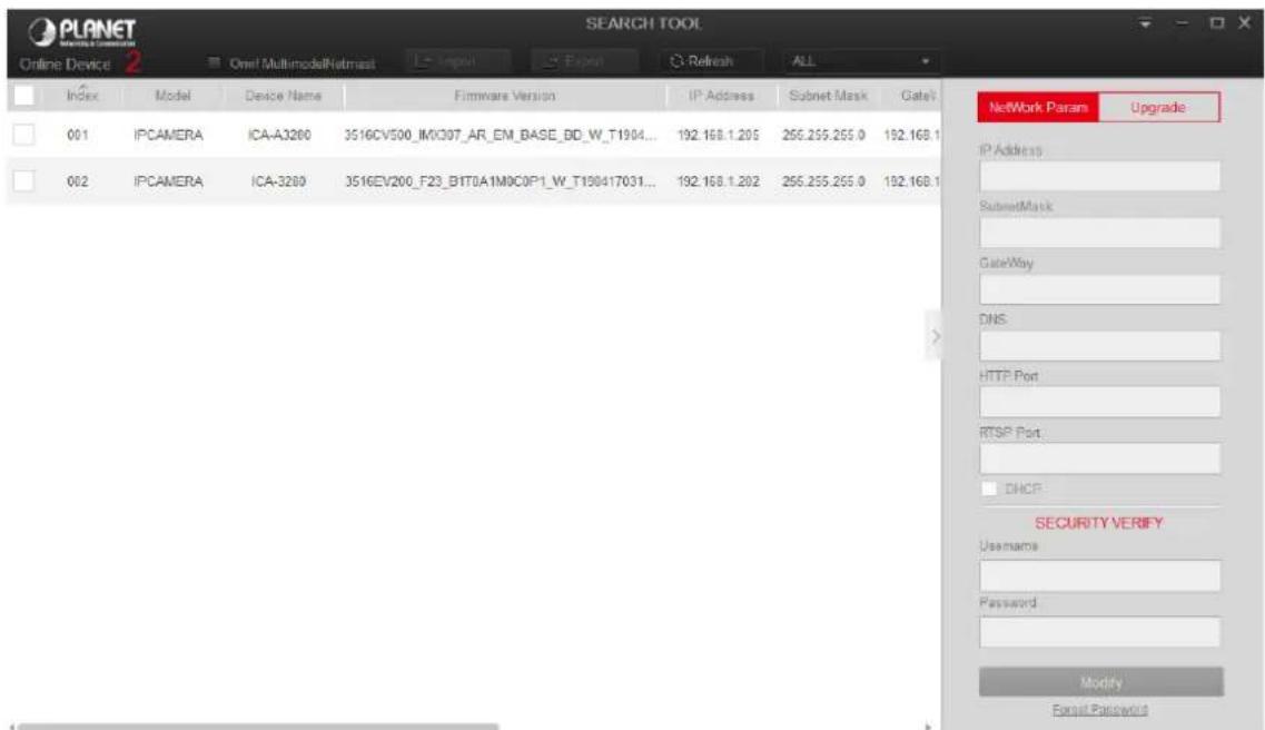
Figure 2-2
- Use the PVMS client software to search for online devices. For details, refer to the PVMS User Manual.
Step 2: Modify the IP address of the IP camera and connect the computer to the same network segment.
- In the PLANET IP search tool, select the device to directly modify the IP, found on the right side of the interface by entering the password, and then click "Modify".
Step 3: Open the browser to enter the IP address of the camera as the web login screen appears.

- When setting up the IP address of the IP camera, keep the device IP address and the computer IP address in the same LAN segment.
- The default IP address is 192.168.0.20 and the port number is 80. The default administrator user name is "admin", and password is "admin". And you are highly recommended to "Modify" the initial password after your first login.
- To access the IP camera of different subnets, set the gateway of the IP camera after login. For details, see 8.3.1 Configuring TCP/IP.
Chapter 3 Access to the IP Camera by PVMS Software
The PVMS software is available on the company website (www.planet.com.tw). You can use this software to view live video and manage IP camera. Follow the installation prompts to install the software. The control panel and real-time view interface of the PVMS software are shown in Figure 3-1.
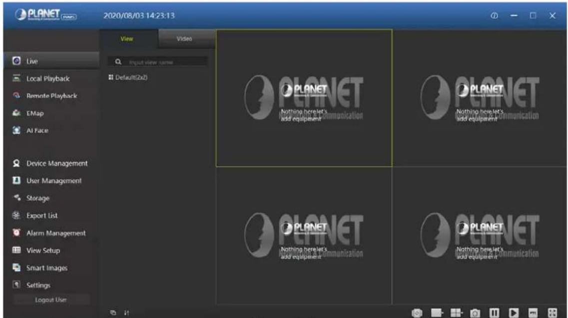
Figure 3-1

- For detailed information about the software, refer to the user manual of the PVMS Software.
Chapter 4 Access to the IP Camera by Web Client
4.1 Preparation before installing plugin
To ensure the IP camera and the current user's computer after completion of Make sure all the hardware connections and power equipment are normal before switching on the computer and running a ping for the IP address of the IP camera (Note: The IP address of the IP Camera in LAN must be unique.), such as 192.168.0.20. If the IP camera responds, it indicates that the network connection is normal; you can open a browser to log in to web page.
4.2 Login and Exit
4.2.1 Login
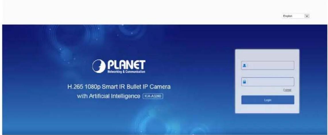
Open a browser on your computer and enter the IP camera address in the web address bar (the default address used for the first time is: http://192.168.0.20) to enter the login interface, as shown in Figure 4-1.
Copyright@PLANET Technology Corporation. All rights reserved.
Figure 4-1
Select a system language (Simplified Chinese, Traditional Chinese, English, Russian, Korean, Polish, French, Japanese, Spanish, Portuguese, Italian, Hebrew, Turkish, Bulgarian, Arabic, German, Dutch, Czech or Vietnamese), and enter the username (default is "admin") and password (default is "admin") to log in.

- If you have modified the IP address of the IP camera, log in with the newly set IP address.
4.2.2 Changing password
After the successful login, the interface prompts to change the password, as shown in Figure 4-2:
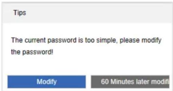
Figure 4-2
For the account security recommendations, click "Modify" and enter the user interface to modify the password, as shown in Figure 4-3:
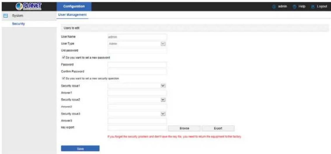
Figure 4-3
To change your password, follow these steps:
Step 1: Enter the old password and enter the new password in the Password and Confirm Password fields;
Step 2: Set security questions 1, 2, and 3 and enter the answers.
Step 3: Click "key export" to save the key file to your computer.
Step 4: Click "Save" to complete the password modification.
- When setting a new password, you must set at least 8 digits and contain both letters and numbers to set it successfully.
- When the IP camera password is the initial password "admin", each time you log in, you will be prompted to change the password. You can select "After 60 Minutes later modified". After 60 minutes, the interface will automatically pop up the password modification interface.
4.2.3 Forget password
When you forget your password, you can reset the password in two ways: security question verification and security key verification.
Security question verification
Step 1: On the login interface, click "Forget".
Step 2: Select the verification method as "Security question validation" (as shown in
Figure 4-4 ), enter the answers to security questions 1, 2, and 3, and click "Next"
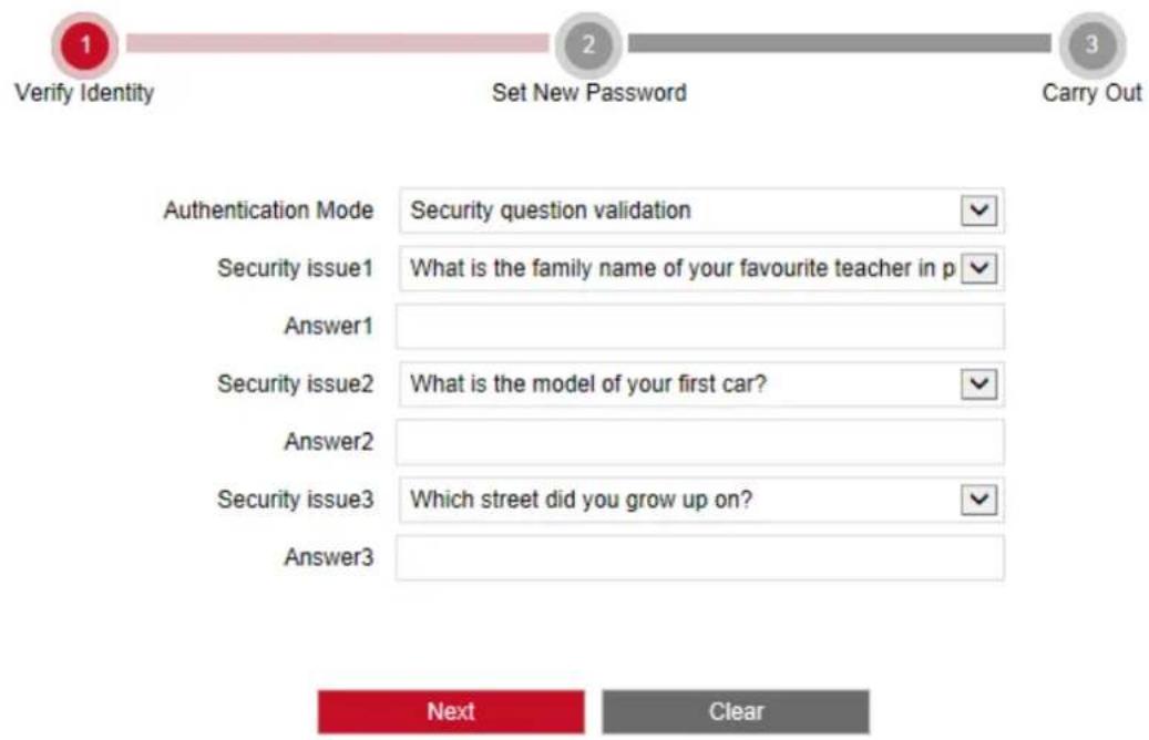
Figure 4-4
Step 3: Enter the new password and confirm the password (as shown in Figure 4-4 0), and click "Next".
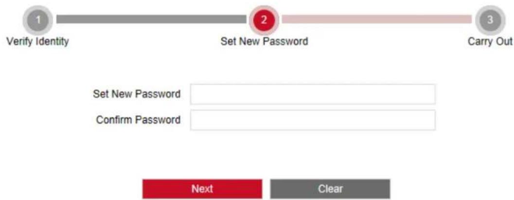
flowchart
graph LR
    A["1 Verify Identity"] --> B["2 Set New Password"]
    B --> C["3 Carry Out"]
    D["Set New Password"] --> E["Confirm Password"]
    F["Next"] --> G["Clear"]
Figure 4-4 ∅
Step 4: Click "Re-login" to return to the login interface (as shown in Figure 4-4 3).
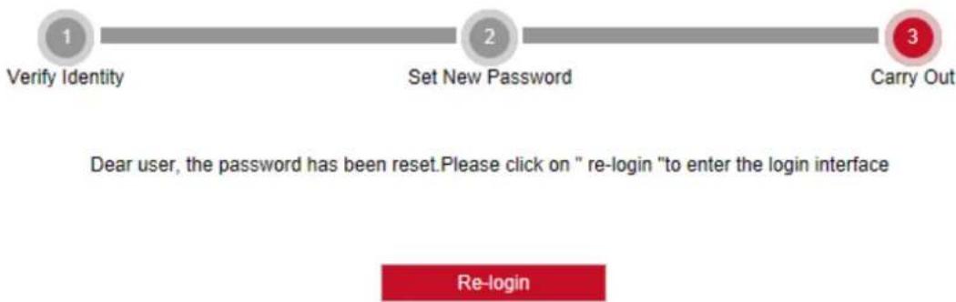
flowchart
graph LR
    A["1\nVerify Identity"] --> B["2\nSet New Password"]
    B --> C["3\nCarry Out"]
    D["Dear user, the password has been reset. Please click on " re-login " to enter the login interface"]
    E["Re-login"]
Figure 4-4 ③
Security Key verification
Step 1: On the login interface, click "Forget".
Step 2: Select the verification method as "Security Key Verification" (as shown in Figure 4-5 ), and click "Import" to import the key file exported when the password is modified;
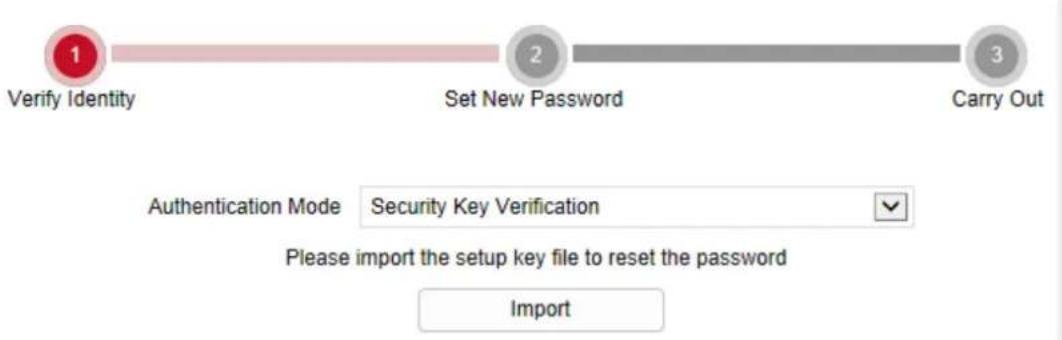
flowchart
graph LR
    A["1 Verify Identity"] --> B["2 Set New Password"]
    B --> C["3 Carry Out"]
Figure 4-5
Step 3: Enter the new password and confirm the password (as shown in Figure 4-5 2), and click "Next".
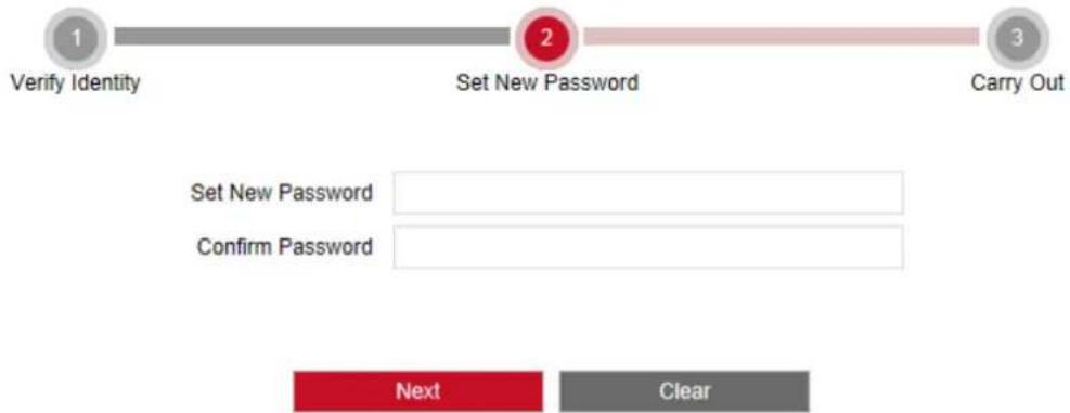
flowchart
graph LR
    A["1 Verify Identity"] --> B["2 Set New Password"]
    B --> C["3 Carry Out"]
    D["Set New Password"] --> E["Confirm Password"]
    F["Next"] --> G["Clear"]
Figure 4-5
Step 4: Click "Re-login" to return to the login interface (as shown in Figure 4-5 3).

flowchart
graph LR
    A["1\nVerify Identity"] --> B["2\nSet New Password"]
    B --> C["3\nCarry Out"]
Dear user, the password has been reset. Please click on "re-login" to enter the login interface
Figure 4-5 ③
- When selecting "Security question validation", enter the correct answers to 2 questions to enter the "Set New Password" interface and proceed to the next step.
- When setting a new password, you must set at least 8 digits and contain both letters and numbers to set it successfully.
- An IP camera key file can be used multiple times to reset the password if you forget it.
4.2.4 Exit System
When you enter the IP camera main interface, you can click the upper right corner of the
safe exit system.
4.3 Installing the HsIPCCtl Controls

- When you use IE browser or 360 browsers, you need to download and install the controls after login.
Open Internet Explorer and log in to IP camera to enter the download interface, as shown in Figure 4-6.
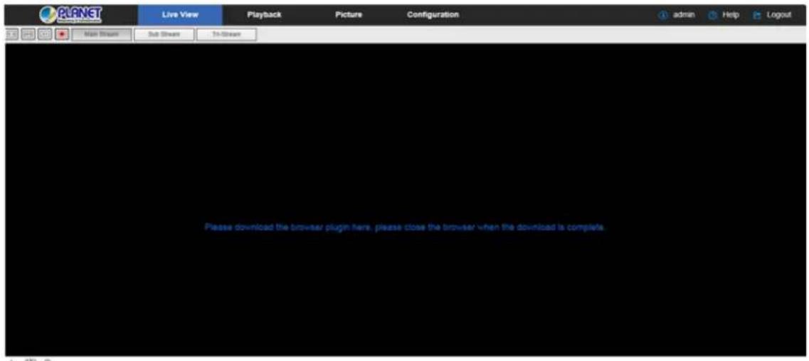
Figure 4-6
Click "Please download the browser plugin" here and close the browser when the download is completed. → "Run" → "Next" → "Next" → "Next" → "Next" → "Finish".
Follow the instructions in Figure 4-7 (1、2、3、4、5、6) to complete the installation:
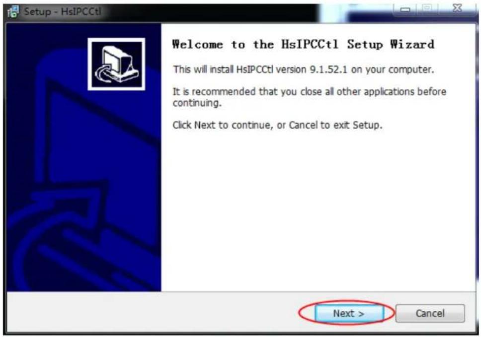
Figure 4-7
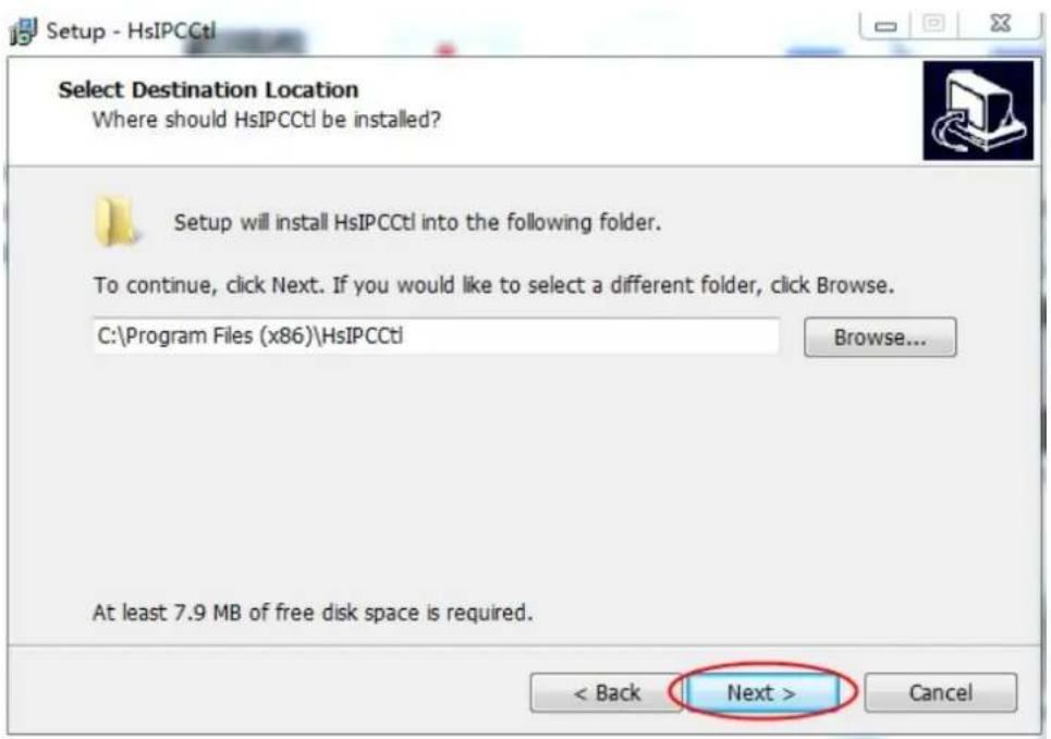
Figure 4-7 ☉
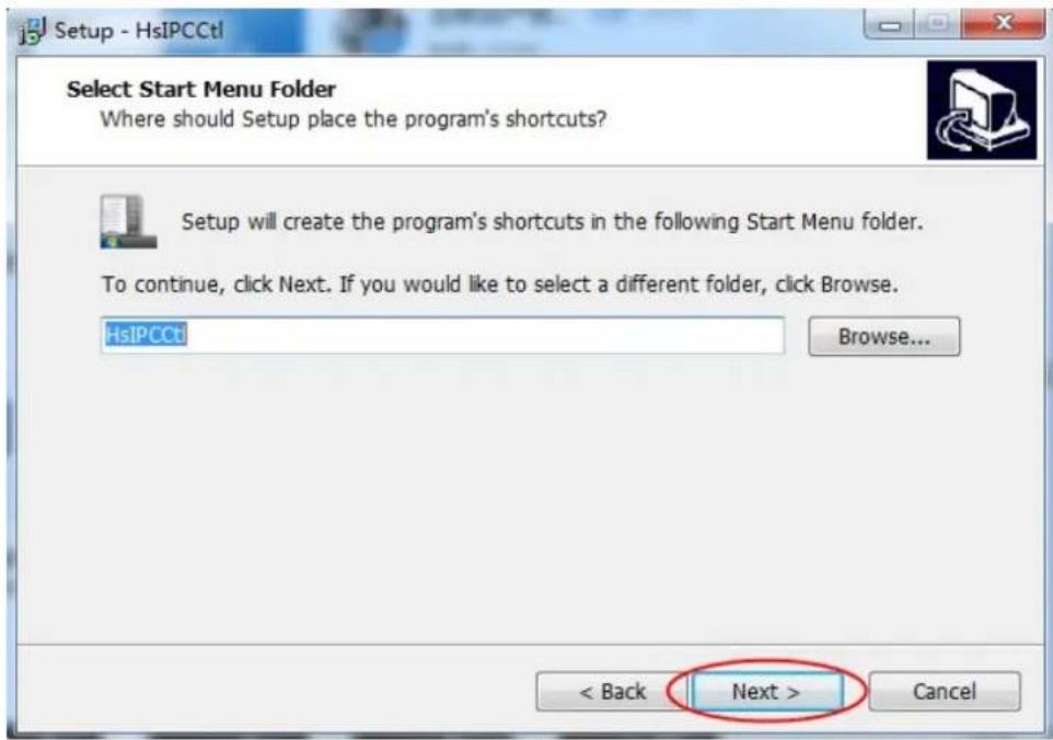
Figure 4-7 ③
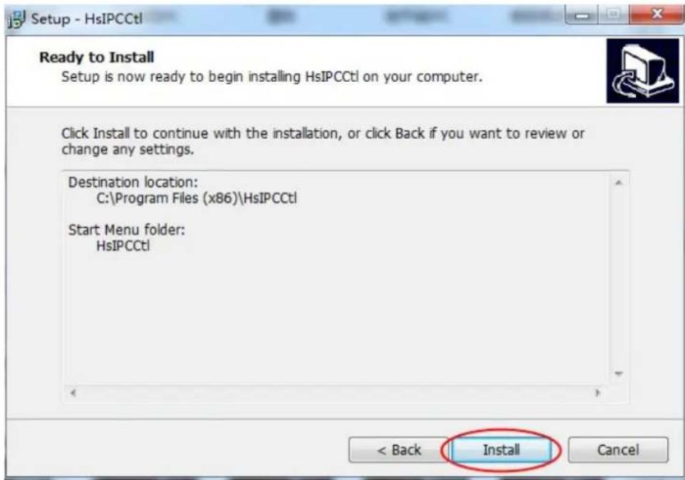
Figure 4-7 ④
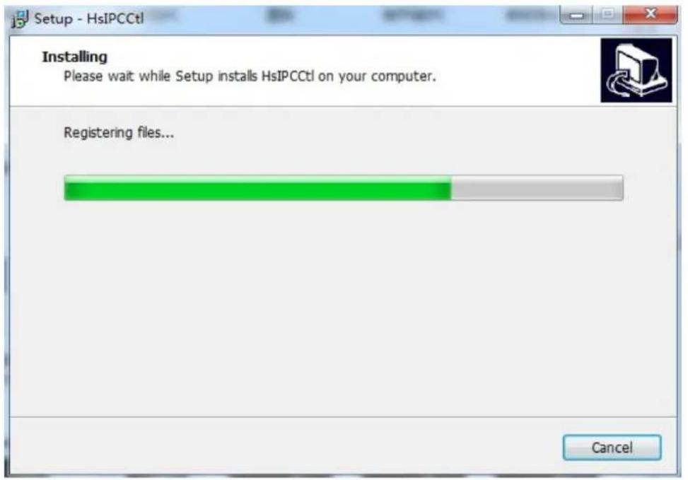
Figure 4-7 5
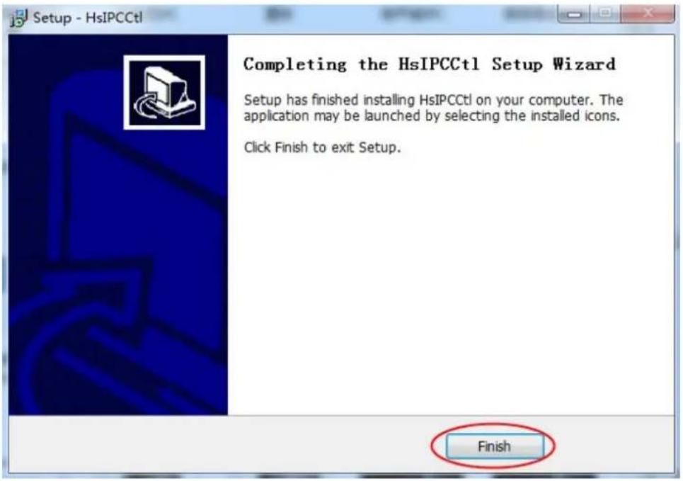
Figure 4-7 6

If the system prompts "installation failure", please uncheck the "cancel protection mode" in the setting safety of "Internet options" and enter the "custom level" ActiveX control Settings as shown in Figure 4-8, and reinstall HsIPCCtl after save settings.
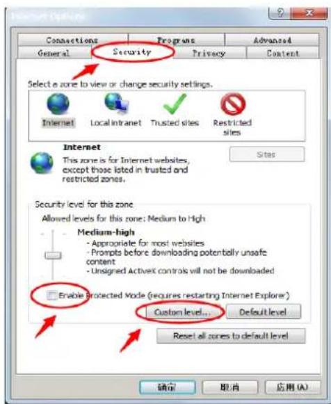
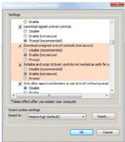
Figure 4-8
4.4 Main interface description
In the IP camera main interface, you can preview real-time video, playback, configuration and PTZ control and other functions as the interface is shown in Figure 4-9:
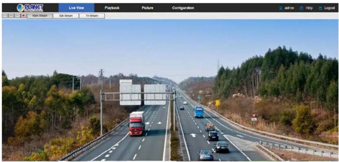
Figure 4-9
【Live View】 For IP camera monitoring preview, you can switch the code stream preview. Previews include video, capture, electronic zoom and other functions.
【Playback】Select the time or video type to find the device TF card in the video and playback.
【Picture】Used to query, view and download image files stored in the IP camera SD card.
【Configuration】 Click into the IP camera configuration interface for system
configuration and function configuration.
【PTZ Control】Used to set the PTZ preset point, cruise line and PTZ rotation direction preview real-time video and so on.

- For IP camera main interface layout function and other information, always use the actual equipment provided.
Chapter 5 Live preview
5.1 Live preview
Click "Live View" to enter the IP camera preview interface, as shown in Figure 5-1:
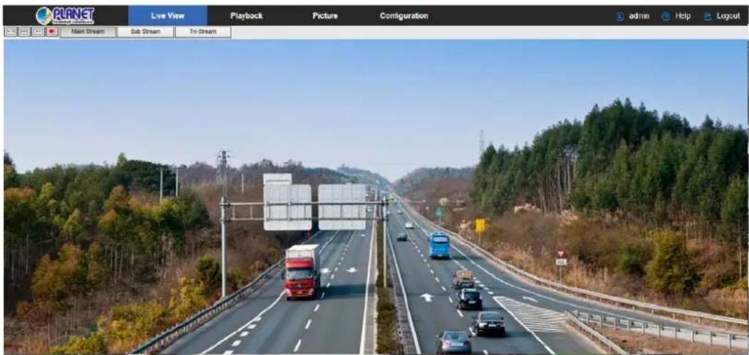
Figure 5-1
【switching window size】In the real-time preview interface on the top left of the preview ratio option, click "4: 3", "16: 9", "X1", "full screen" to switch the video preview scale.
【switching option】 In the upper left of the real-time preview interface, there is a stream switching option. Click "Main Stream", "Sub Stream" and "Triple Stream" to switch preview video stream.
The preview interface operation buttons are shown in Table 5-1.
| Icon Description | |
 | The window size is 4:3. |
 | The preview screen is displayed in its original size. |
 | The window size is 16:9. |
 | Self-adaptive window size. |
| Main Stream/Sub Stream/Tri-stream | To switch the real-time preview stream (The main stream is a high-definition stream, and the sub-stream is a standard definition stream), take the actual function of the device. |
 | Start/Stop live view. |
 | Manually start/stop recording. |
 | Manually capture the picture. |
| [072A] | Turn on / off the electronic zoom function -- Turn on the electronic zoom function in the preview image, and hold down the left mouse button to select the electronic zoom area as the interface shows the region to enlarge the image |
 Open/Close Sound Open/Close Sound | Turn on/off Sound. |
| [2Y28] | Open / Close talk back. |
Table 5-1
5.2 Camera settings: PTZ, zoom and cruise
Click "
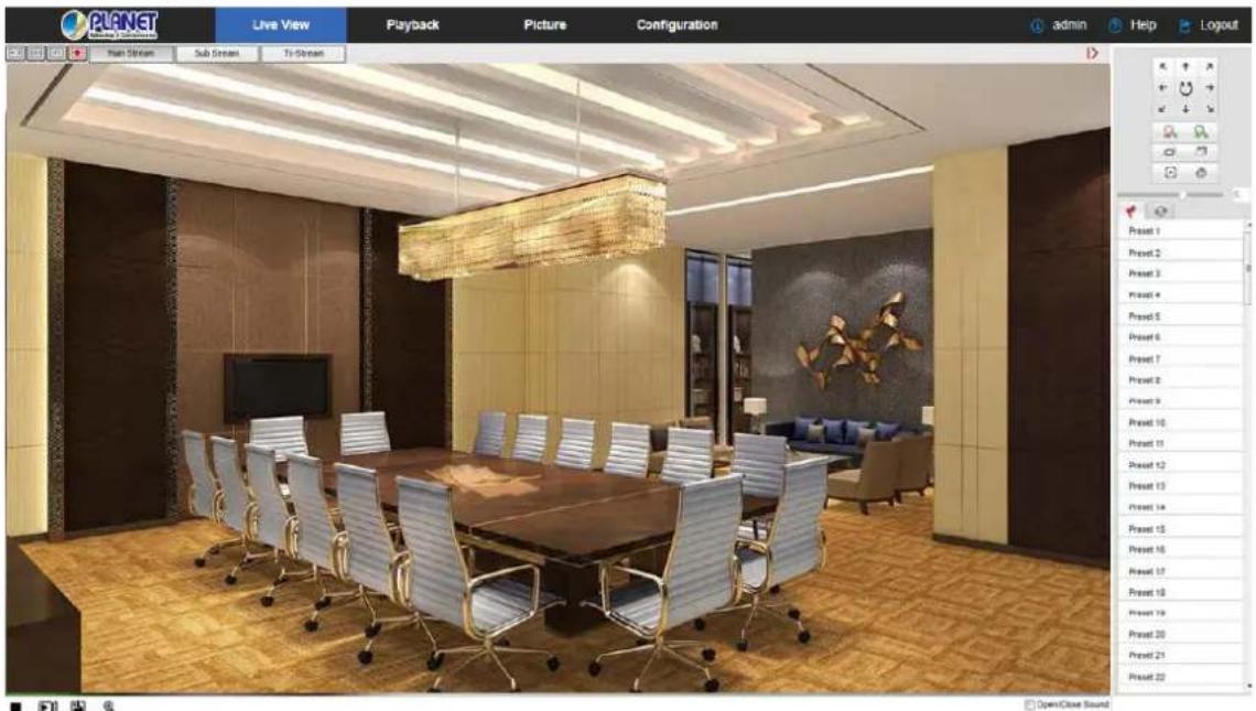
Figure 5-2
The PTZ control menu is shown in Figure 5-3 below:
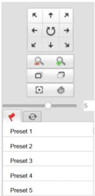
Figure 5-3
The PTZ control interface operation buttons are shown in Table 5-2 below.
| Buttons Description | |
 | Long press the arrow keys to control the horizontal or vertical direction, such as vertical rotation. (Note: One of the bolts can only rotate horizontally, and does not support vertical rotation).Click " 🔊" and the IP camera will continue to rotate horizontally, and then the button will turn red. Click once to stop it from turning. |
 | "Zoom-" and "Zoom +".Hold down the " 🔊" to zoom in; hold down the " 🔊" to zoom out. |
 | "Focus-" and "Focus +".In manual focus mode, adjust the " 🔊" and " 🔊" keys to make the objects within the scene clear. |
 | One Key Focus. |
 | Init Camera. |
 | Adjust the speed of rotation of the pan / tilt. |
| Preset | |
| [SYHD] | Click Preset to enter the Preset Settings menu and click the Presets icon to edit and recall the preset points.To select the preset number, click the "button after the number is preset. Turn to the preview channel image to make the image stay in a certain position. Click the "button to call the preset point rotation; click the "button to clear the preset point. |
 | CruiseClick "Cruise" to enter the cruise settings menu to edit.Select a cruise path, click the cruise path "to enter the cruise path interface, select the preset point number, set the speed and time, and click "OK". Use this method to add multiple preset points, and finally click the "Button to save, or call the cruise line. |
Table 5-2
  | Some cameras that support PTZ, Zoom, Preset, Cruise, etc. have a PTZ control button related interface. Please refer to the specific device.Zoom camera without cruise function; PTZ can only rotate horizontally, and does not support vertical rotation.PTZ control function only supports the camera with PTZ function or PTZ camera; please refer to the actual function of the specific equipment.Up to 128 preset points are configured.A cruise line must set at least 2 preset points."One Touch" and "Lens Initialization" are available for cameras equipped with an electric lens. Due to the limitation of the scene, the effect of the one-button focus function may not be as expected. In this case, it is recommended that you manually click the focus button to complete the focus operation. In the models with the electric lens, PTZ speed adjustment can be made to change the focus and zoom speed.Click the "one-click focus" to automatically complete the focus action. When the "one-click focus" appears difficult to focus on a clear case, click the "lens initialization". For the lens parameters to go back to the initial position, click "You can focus clear". |
Chapter 6 Playback
In the main interface, click “Playback” into the video playback interface. Playback
interface can be stored in the camera SD card / TF card within the video file for query, playback and download operations, as shown in Figure 6-1:
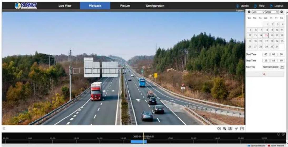
Figure 6-1
Here you can choose the video type (ordinary video or alarm video) and video time to query SD / TF card in the video file, and the query to the video file playback, screenshots, clips and download.
【Video search】To select the start time, end time, file type "normal video" or "alarm
video", click " 🔒" to find and meet the conditions of the video file which is found on the right side of the calendar interface and then select the red date (red date on behalf of the day of video). Select the start time, displayed on the timeline.
【Play/Stop】After searching for the video, click “▶” to start playing the video. At this time, the button becomes “☐” and click to stop playing the video.
【Drag and drop】For video playback, the left mouse button click on the time axis to play the position, drag left and right, drag it to the middle of the yellow time point position, playback channel to play the point in time recording.
【Electronic zoom】During video playback, click “ ✉”, press and hold the mouse to select the area to be enlarged in the playback interface. Release the mouse and the area is enlarged, click the right mouse button to restore the zoom, then the button becomes

click to close the electronic zoom.
【Capture】 For video playback, click " " to capture the current playback screen image; the interface pops up the capture picture folder, which shows just captured the picture.
【Video cut】For video playback, click " ", start the current playback video to start recording, click " again to stop the video; the interface pops up the clip folder, which shows just the clip video.
【Audio】If the video file has audio, click the “ ” audio button during playback to turn on and off the playback of the recorded file. You can also adjust the volume by dragging the volume.
【Timeline magnification】Click the right side of the window on the right side of the "

button and the interface below shows the time axis that is enlarged to the maximum
of 5min a grid.
【The timeline is reduced】When the timeline is zoomed in, click the "⊖" button to return to the recording timeline before zooming in.
【Video File Query and Download】 Select the date, time period and video type in the calendar. Click "" on the right side of the window to pop up the video download interface. The interface will automatically search all the video files of the corresponding time range and video type, as shown in Figure 6-2:
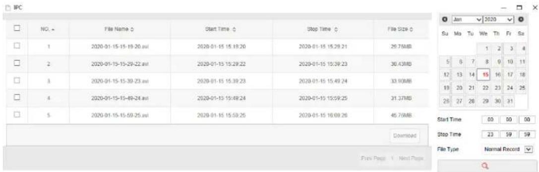
Figure 6-2
【Prev Page】Flip function -- click to switch to the previous page.
【Next Page】Flip function -- click to switch the next page.
【Download】Select "☐" in front of the serial number of the file to be downloaded; click
"Download" → "Save", set the download file storage path, the file starts to download, and wait for the download progress to complete.
● Make sure the IP camera has an SD card slot and video playback function.
- Before querying the video, make sure that the SD card status in the device is "in use" and the 8.2.5 Rec Setup have been configured.
- Please refer to 8.1 Local Configuration for the settings of the video and picture saved in the playback interface.
Chapter 7 Picture
Picture
Click “Picture” in the main interface to enter the Picture interface. The picture interface can query and download the picture files stored in the camera SD card, as shown in Figure 7-1.
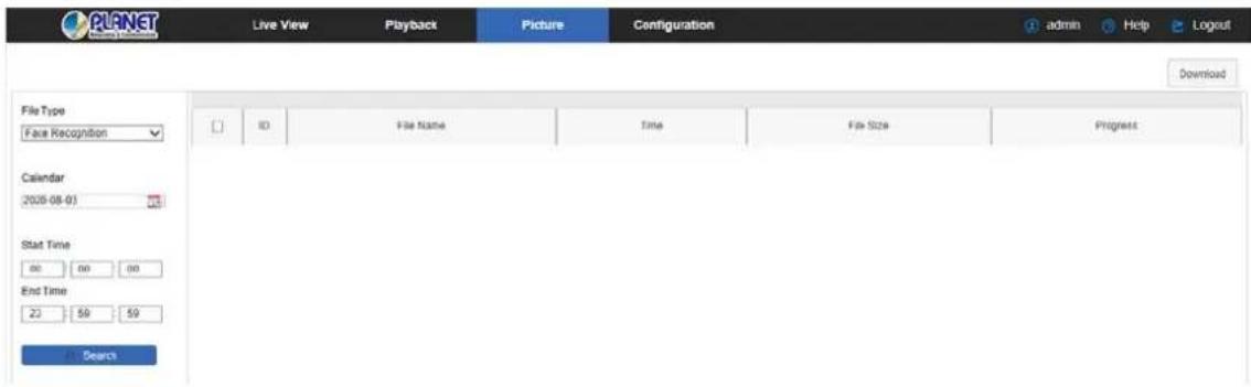
Figure 7-1
【Query】 Select the file type on the left side of the interface to set the image query time,
and click " Search " to list the eligible image information in the list on the right.
【Download】 Check the image you want to view and click "Download" to save the image information to your local computer. Multiple images can be downloaded at the same time.

- The picture is stored in the "Save download files to" of "Configuration → Local Configuration".
Chapter 8 Configuration
Configuration
Click "Configuration" in the main interface to enter the local configuration interface. Here you can set the device system, network, video, images, events and other parameters.
8.1 Local Configuration
In the main interface, click "Configuration → Local Configuration" to enter the local
configuration interface, where you can set the "Record File", "Picture and Clip", "Log Export", "Online Upgrade", "Import / Export Param" storage path. Change the path by selecting Browse, as shown in Figure 8-1 below:
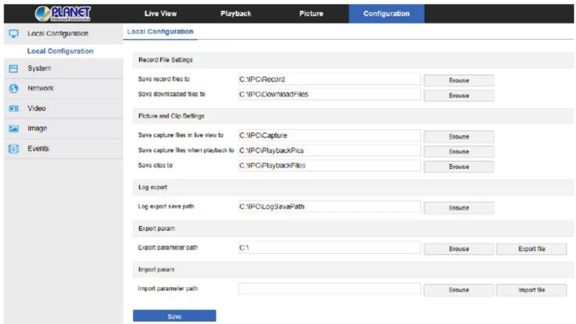
Figure 8-1
【 Record File Settings】 Set the saving path of the recorded video files. The recorded files you recorded are valid with the web browser.
【 Save record files to】 Set the saving path for the manually recorded video files.
【 Picture and Clip Settings】 Set the saving paths of the captured pictures and clipped video files. The pictures you captured are valid with the web browser.
【 Save capture files in live view to】 Set the saving path of the manually captured pictures in live view mode.
【 Save capture files when playback to】 Set the saving path of the captured pictures in
playback mode.
【Save clips to】 Set the saving path of the clipped video files in playback mode.
【Export param】Set device parameters in the computer's storage path, used to save the web-side device parameters of the file.
【Export parameter path】 Set the storage path for IP camera export parameters.
【Import param】Set device parameters in the computer's storage path, the file used to save the parameters of the web page egg device.
【Import parameter path】Set the storage path for the IP camera import parameters.
8.2 System
In the main interface, click "Configuration → System" to enter the system configuration interface. The system consists of system configuration, scheduled reboot, log query and security.
8.2.1 System Configuration
In the main interface, click "Configuration → System → System Configuration" to enter the system configuration interface.
Device Information
In the System Configuration interface, click "Device Information" to enter the device information configuration interface, where you can view the basic information of the current device, as shown in Figure 8-2:
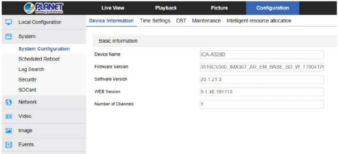
Figure 8-2
【Device Name】The name of the current IP Camera.
【Firmware Version】 The current version of the IP Camera.
【Software Version】 The current HsIPCCtl control version of the IP Camera.
【WEB Version】The current page version of the IP Camera.
【Number of Channels】The current channels of the IP Camera; the default is 1.
∅ Time Setting
In the System Configuration interface, click "Time Settings" to enter the time setting interface, where you can set the device time, as shown in Figure 8-3 below:
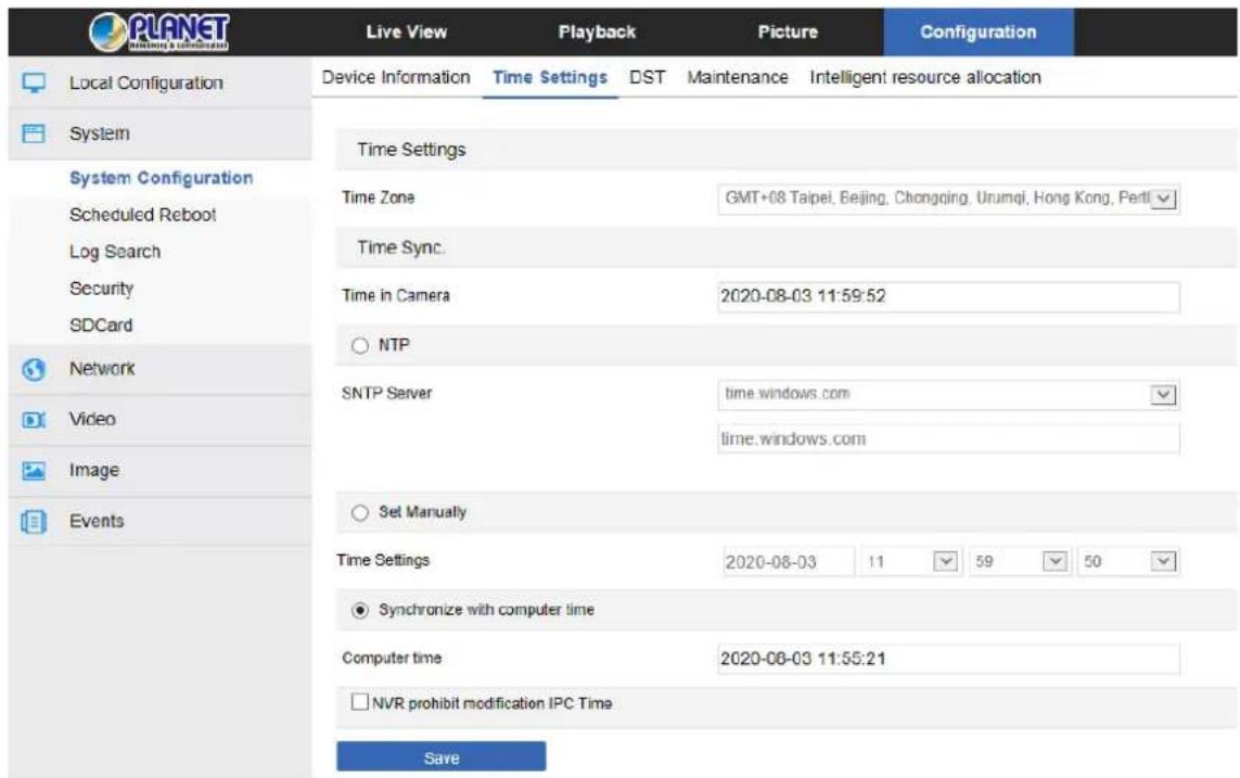
Figure 8-3
【Time Zone】Displays the current device selection time zone.
【Time in Camera】Displays the current time of the device.
【NTP】The IP Camera time will synchronize with network, and you can change the different time zones. (This feature requires IP Camera network environment to be connected to the Internet.) Click on the "Save" after completing the settings.
【SNTP Sever】SNTP server address, including "time.windows.com", "time.nist, gov", "time-nw.nist.gov", "time-a.nist.gov", "time-b.nist.gov" Optionally, you can also enter the
SNTP server address through "Customize".
【NTP auto-time】After it is enabled, IP Camera performs time synchronization with the SNTP server at the time interval.
【Time interval】The time interval between the IP Camera and the SNTP server is 1 minute by default. You can set "1 \~ 10080".
【Set Manually】To set the IP Camera date and time manually, click on the "Save" after completing the settings.
【Synchronize with computer time】The IP Camera will synchronize with the computer time and date that you connect currently. Click on the "Save" after completing the settings.
【NVR prohibit modification IP Camera time】The IP Camera time will not be affected by the backend storage devices (such as NVR, etc.) after checking this option. The IP Camera time will run according to the user settings.
③ DST
Daylight saving time (DST) refers to the system of artificially stipulating local time for energy conservation. The unified time used during the implementation of this system is called "DST". In the System Configuration interface, click "DST" to enter the daylight saving time setting interface, where you can enable daylight saving time, set daylight saving time, end time and end time, as shown in Figure 8-4:
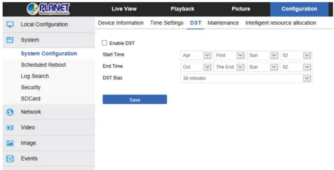
Figure 8-4
In the System Configuration interface, click "Maintenance" to enter the system maintenance settings interface, where you can restart the device, restore factory settings, do manual upgrade, as shown in Figure 8-5:
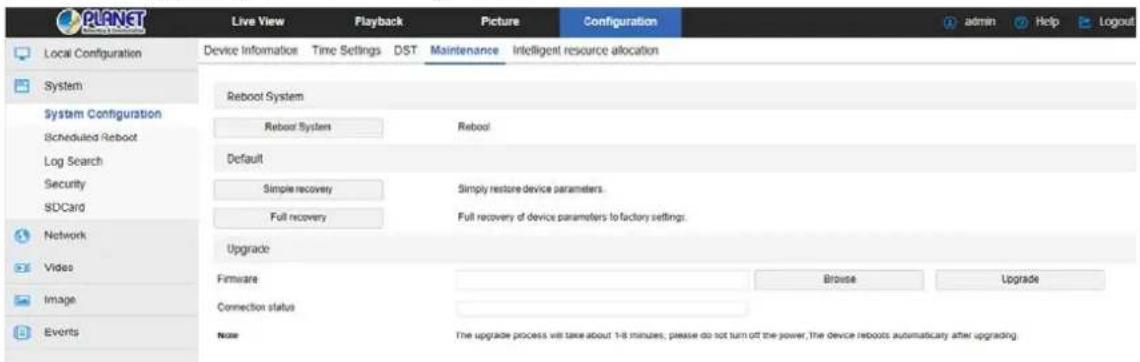
Figure 8-5
【Reboot System】 The IP Camera will restart again automatically after clicking "Reboot System".
【Default】 Divided into Simple recovery and Full recovery.
After clicking "Simple recovery", IP Camera will automatically restore the parameters to the factory parameters except the network parameters.
After clicking "Full recovery", all parameter settings of IP Camera will be automatically restored to the factory parameter settings (please operate this function carefully).
【Upgrade】Click "Browse" to add upgrade file package, and upgrade the IP Camera program. (Careful operation must be followed to eliminate errors or else equipment system may operate abnormally.)
8.2.2 Scheduled Reboot
In the main interface, click "Configuration → System → Timing Reboot" to enter the
scheduled reboot settings interface, where you can set the time for the device to restart, and set the restart "cycle" in the drop-down menu, for example, set "3:00 on the 3 ^rd of each month" and click Save. IP Camera will reboot at 3 o'clock on the 3 ^rd , as shown in Figure 8-6 below:
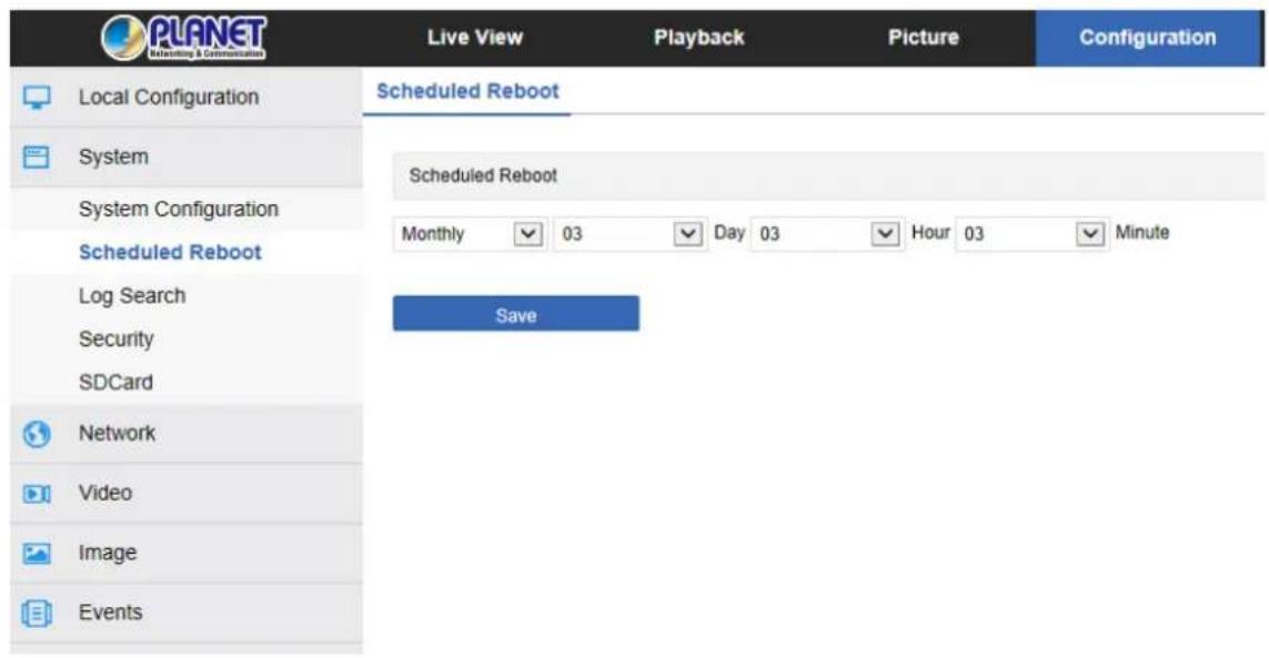
Figure 8-6
8.2.3 Log Search
In the main interface click on the "configuration → system → log query" into the log query interface, where you can query the device login, account number, alarm and all other relevant information, as shown in Figure 8-7 below:
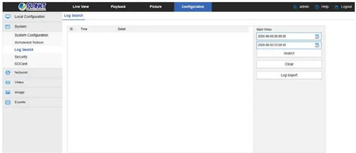
Figure 8-7
【Search】 To set the date and start time of the log query, click "Search" and the log list shows the IP Camera execution record that meets the conditions.
【Clear】Click the clear button to empty all loggins.
【Log export】Save the contents of the current log to the location you specified in txt format.
8.2.4 Security
In the main interface, click "Configuration → System → Security" to enter the user
management settings interface, where you can add, edit and delete the user, and you can also query the current user information. The current user name for the administrator is "admin". You can create up to 10 user names, as shown in Figure 8-8:
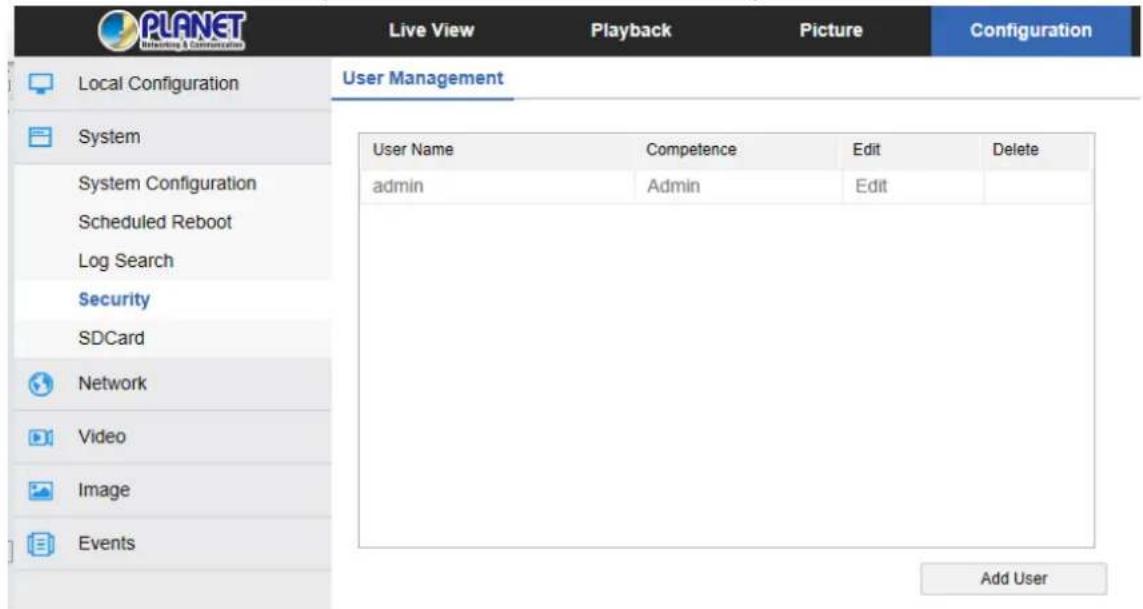
Figure 8-8
① Add a User
Step 1: Click "Add User" to add a user.
Step 2: Input the User Name, select User Type and input Password.
Step 3: Click "Ok" to complete the added user name.
Figure 8-9 shows how to add a new user name.
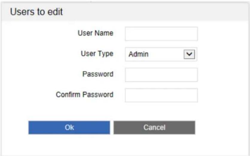
Figure 8-9

Cautions
- In order to improve the security of the product network, please change the password of the user name regularly. It is recommended to change it every 3 months. If the IP camera is used in a high security risk environment, it is recommended to update once a month or every week.
- It is recommended that the system administrator manages the user effectively, removes the unrelated user and shuts down the unnecessary network port.

- The admin user cannot be deleted and you can only change the admin password.
- User permission description: Administrator -- all permissions.
Operator -- All permissions (cannot make system security parameter settings).
Viewer -- only preview permission. - When setting the IP camera password, the password length is 8-31 characters and must contain numbers and letters.
Password strength rules are as follows:
- If the set password contains three or more types (numbers, lowercase letters, uppercase letters, special characters), it is a strong password.
- If the password is set to a combination of numbers and special characters, lowercase letters and special combinations of characters, capital letters and special characters, lowercase letters and uppercase letters, are in the password.
- If the password is set to a combination of numbers and lowercase letters, numbers and uppercase letters are weak passwords.
- Password length is equal to 8, the password contains only one type of character, password and user name or password is the user name of the write, the above types of passwords are risk password, do not recommend this set.
To better protect your privacy and improve product safety, we recommend that you change your risk password to a high-strength password.
∅ First modified (admin user) password
Step 1: In the user list, click the "Edit" button after the admin user to enter the user interface.
Step 2: Enter the old password (Default password is "admin") and enter the new password in the Password and Confirm Password fields.
Step 3: Select security questions 1, 2, 3 and set the corresponding answers, and click "key export" to export the key file to your computer.
Step 4: Click "Save" to complete the password modification.
③ Modify the (admin user) password again
Step 1: In the user list, click the "Edit" button after the admin user to enter the user interface.
Step 2: Enter the old password, check "Modify Password", and enter a new password in the Password and Confirm Password fields:
Step 3: Click "Save" to complete the password modification.
- When the IP Camera password is the initial password "admin", each time you log in, you will be prompted to change the password. You can select "Modify after 60 mins". After 60 minutes, the interface will automatically pop up the password modification interface.
- When modifying the administrator password, after setting the security question, click "Browse" to select the path, and click "Export" to export the key file, so that the password can be reset when the password is forgotten.
- After modifying the administrator password, when the PC and the device are on the same LAN segment, click "Forget" to reset the password by answering the security question or importing the key.
- When you change your password again, you don't have to set a new security question. When you forget your password, you can reset it with the last security question you set.

Note
④ Edit the User (new user)
Step 1: In the user list, select the user to be modified, and click "Edit" to enter the user editing interface.
Step 2: Edit the user type or password, enter the confirm password;
Step 3: Click "Ok" to finish editing the user.

- The password setting rule is the same as the password rule when adding a user.
5 Delete Users
Step 1: Click to select the user you want to delete and click "Delete".
Step 2: Click "Ok" on the pop-up dialogue box to delete the user.
8.2.5 SD Card
①SD Card
In the main interface, click "Configuration → System → SDCard" to enter the SD Card management settings interface, here you can view the SD card related information and format the SD card as shown in Figure 8-10:
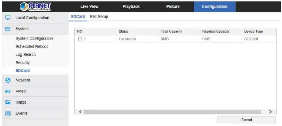
Figure 8-10
SD card format steps are as follows :
Step 1: Select the disk to be formatted by clicking "Format";
Step 2: Click "OK" in the pop-up prompt box;
Step 3: Wait for the format to complete the progress bar. When formatting is complete,
check the card information, Total Capacity = Residual Capacity, formatted successfully.
2Rec Setup
In the main interface, click "Configuration → System → SDCard → Rec Setup" to enter the recording setting interface, here you can open the SD card video, set the SD card recording schedule and stream type, as shown in Figure 8-11:
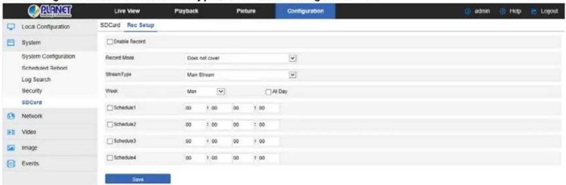
Figure 8-11
8.3 Network
In the main interface, click "Configuration →Network" to enter the network settings interface, the network is divided into Basic Setup and Advanced Setup configuration.
8.3.1 Basic Setup
TCP/IP
In the main interface, click "Configuration → Network → Basic Setup → TCP / IP" to enter the TCP / IP interface. Here you can set the IP address, subnet mask, gateway, and DNS of the device as shown in Figure 8-12 below.
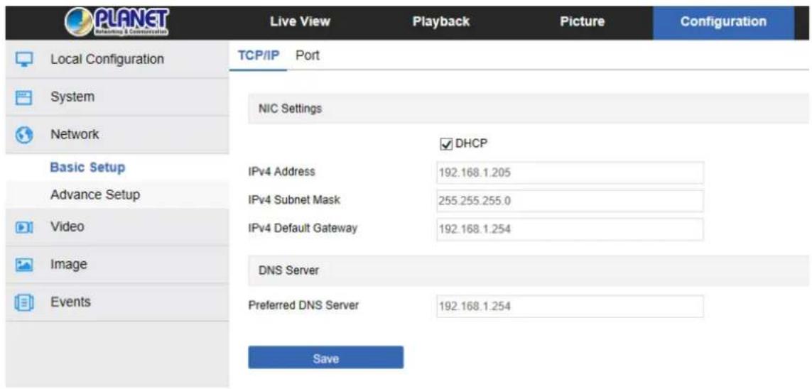
Figure 8-12
The IP Camera is connected to the routers that have opened the DHCP function. Check the DHCP option, and the IP camera can automatically get IP address, subnet mask, default gateway and DNS.
Close DHCP] to manually modify the IP camera IP address, subnet mask, default gateway and preferred DNS server information. Click "Test" to confirm whether the modified IP address is available in the LAN (that is, whether it conflicts with other equipment IP). When it prompts "IP available", click "Save" to complete the settings.
2 Port
In the main interface, click "Configuration →Network → Basic Setup→ Port" to enter the port setting interface, where you can set the IP Camera network port and protocol port. The network port has HTTP port (default is 80), RTSP port (default is 554), HTTPS port (default is 443), and BITVISION port (default is 6000). The protocol port has the ONVIF port (default is 8999), as shown in Figure 8-13 below:
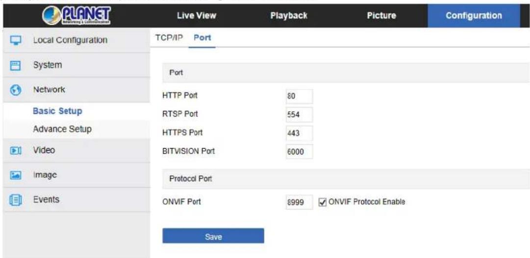
Figure 8-13
【BITVISION Port】When the BitVision App is directly connected to the device, the "Private port" is entered into the BITVISION port.
【ONVIF Port】When the IP Camera accesses ONVIF agreement with the back-end equipment, the ONVIF protocol needs to be enabled.
Please do not arbitrarily modify the port parameters; when there is a port conflict, you need to modify the port number as follows:
- HTTP and HTTPS port: Use the browser login to add the address after the port number. You need enter the HTTP port number (for example, 8555) that you want to change via the browser login.
- Make sure RTSP port (real-time transmission protocol port) is available for modification.
8.3.2 Advanced Setup
In the main interface click on the "configuration → Network → Advanced Setup" to enter the advanced configuration interface, where you can set the device DDNS, FTP, SMTP, platform access, cloud storage and other functions.
① DDNS
In the main interface, click "Configuration → Network → Advanced Setup → DDNS" to enter the DDNS function settings interface, where you can open the IP Camera DDNS function. Select the DDNS type and enter the site name, corresponding to DDNS type user name and password, and click "Save", as shown in Figure 8-14:
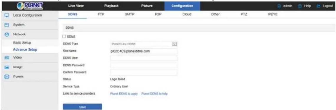
Figure 8-14
【DDNS】 Enable / disable DDNS function.
【DDNS Type】 Choose PLANET DDNS or PLANET Easy DDNS.
【Site Name】The input selection type must correspond to the successful domain name.
【DDNS Account】The input selection type corresponds to the registered account.
【DDNS Password】The input selection type corresponds to the registration password.
【Confirm Password】 Re-enter the password and DDNS password.
【Status】 Shows whether the DDNS of the current device is set up successfully.
【Service Type】Displays the type of user name.
【Links to service providers】Show service provider information.

- Access via DDNS domain requires IP Camera to be accessible to the Internet.
② FTP
Set the FTP (File Transfer Protocol) server and you can store the alarm icon to the FTP server.
Precondition
You need to purchase or download the FTP service tool and install the software on your PC.

- To create an FTP user, you need to set the FTP folder write permission; otherwise the image will not be uploaded successfully.
The steps to configure FTP are as follows:
Step 1: In the main interface, click "Configuration → Network → Advanced Setup →
FTP" to enter the FTP server settings interface, as shown in Figure 8-15.
Step 2: Enter the server address, port, user name, password, and file upload path. Check "Auto Cover", and select to upload the FTP server file format AVI or JPEG.
Step 3: Click "Save" to save the configuration.
Step 4: Click "Test" to confirm whether the network connection and FTP configuration automatically create a folder that you named in the FTP storage path.
【Auto Cover】When enabled, the oldest FTP server will be overwritten automatically when the FTP server is full.
【Upload Via FTP】 In the drop-down menu, select FTP file format, JPEG image format and AVI video for selection. Click on the "Save" after completing the settings.
③ SMTP
In the main interface, click "Configuration →Network → Advanced Setup→ SMTP" to enter the mail settings interface, where you can set the SMTP server information. Enter the sender mailbox, SMTP server address and port, and select the upload SMTP file format, box account and password. To the recipient address, click "Save". The SMTP setup interface is shown in Figure 8-15.
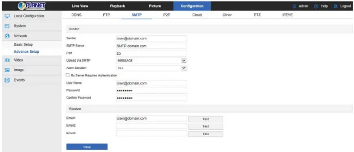
Figure 8-15
Sender
【Sender】Fill in the full address of the sender mailbox.
【SMTP Server】Fill in your email server address.
【Port】 Fill in your email server port.
【Upload Via SMTP】 In the drop-down menu, select SMTP file format, JPEG image format, AVI video and message for selection. Click on the "Save" after completing the settings.
【Alarm Duration】 Set the sending interval.
【My Server Requires Authentication】When enabled, the server and user are authenticated to ensure that the data is sent to the correct client and server.
【User Name】Fill in the send mailbox user name.
【Password】Fill in the send mailbox password.
【Confirm Password】Fill in the send mailbox password.
Receiver
【Email 1, 2, 3】Fill in the full address of your inbox, here up to 3 inboxes, click on the
completion of the "test" to ensure that all the correctness of the input information and network connectivity of the IP camera.
④ P2P
P2P is a private network penetration technology. It does not need to apply for a dynamic domain name, perform port mapping, or deploy a transit server. You can directly scan the QR code to download a mobile client. After registering an account, you can add and manage multiple IP cameras and NVR devices simultaneously on the mobile client. You can add devices in the following two ways to manage multiple devices.
1) Scan the QR code for the mobile phone system, download the app and register the account. For details, see the App User Manual on the website.
2) Log on to the P2P platform, register an account, and add the device via the serial number.
- The device P2P is enabled by default. To use this function, the device must be connected to the external network, and the connection status is displayed as "P2P connection successful". Otherwise, it will not work properly.
P2P steps are as follows:
Step1: In the main interface, click "Configuration → Network → Advanced Setup → P2P" to enter the P2P settings interface, as shown in Figure 8-16 below:.
Step2: Make sure that the IP camera accesses the external network and click "☐" to open P2P.
Step 3: Click "Save" to save the configuration.
Step 4: Refresh page -- the status shows "P2P connection successful". This indicates that P2P is enabled and can be used normally.
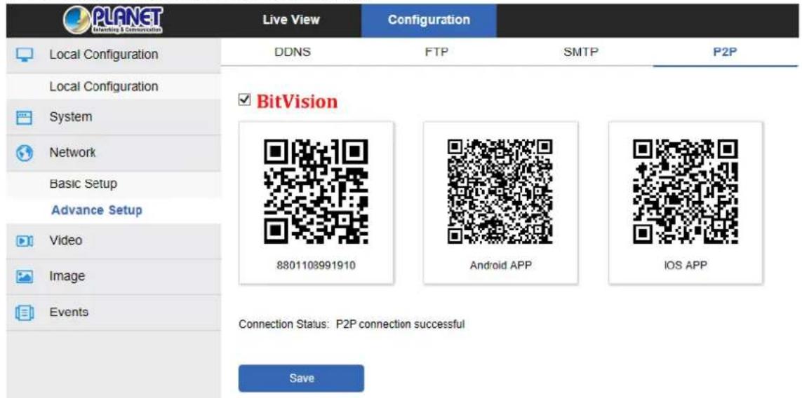
Figure 8-16
App Client operation example
The following content is introduced by taking the operation of the mobile phone client (BitVision App) as an example. The steps are as follows:
Step 1: Use the Android or iOS phone to scan the corresponding QR code to download and install the BitVision App.
Step 2: Run the client and log in to the account (No account is required to register first).
Step 3: Add devices to the mobile client.
After login, click "Device manage", " + " and " Add device", select "SN Add", enter the device user name, password and verification code after scan the QR code (the verification code printed on the label), click "Add" to set device note and group, and click "Send" after adding successfully.
Step 4: Live preview
Select "Real time" and " 🔍 " to enter the device list in the main interface. Select the touching pen and the channel to be previewed in the group. You will see the live video after clicking " Done ".
⑤ Cloud
In the main interface, click "Configuration →Network → Advanced Setup → Cloud" to enter the cloud storage configuration interface, as shown in Figure 8-17 below:
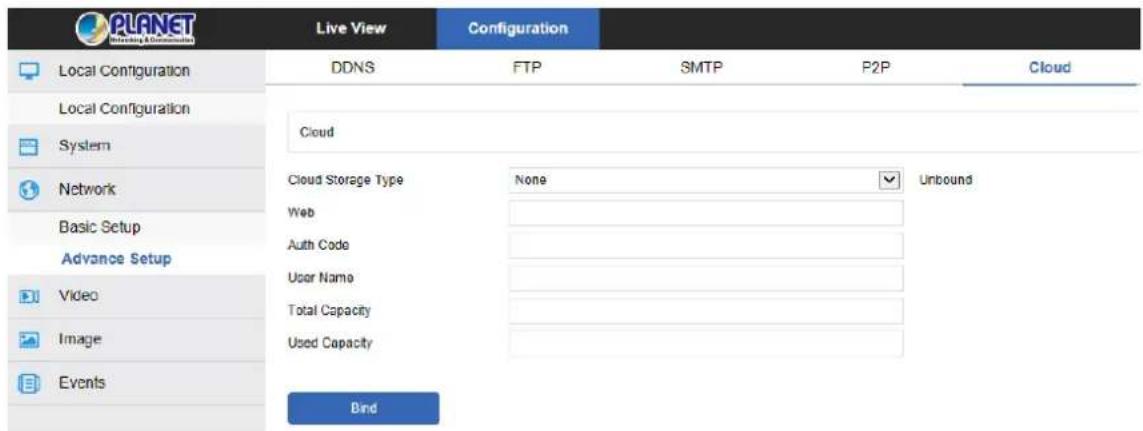
Figure 8-17
【Cloud Storage Type】Select the cloud storage type, Dropbox or Google in the drop-down menu.
【Web】Depending on the type of cloud storage selection.
【Auth Code】Login cloud web, the verification code will display on the cloud storage interface, and then copy it in the space.
Fill in the verification code and click on the "Bind" after the success. "User name", "Total Capacity" and "Used Capacity" will be automatically displayed.
⑥ Other
In the main interface, click "Configuration →Network → Advanced Setup → Other" to enter the Video Password Authentication interface, as shown in Figure 8-18 below:
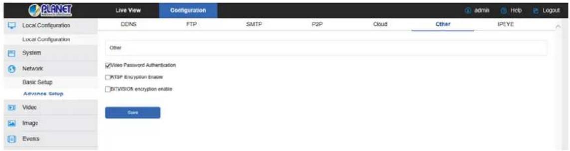
Figure 8-18
【Video Password Authentication】 After opening, encrypt all the devices and platforms connected to the camera video, and connect to the IP Camera video by entering the correct username and password.
【RTSP Encryption Enable】 When enabled, the RTSP stream of the camera is encrypted.
【BITVISION encryption enable】When enabled, encrypt the stream between the camera and the BitVision App.
⑦ PTZ
In the main interface, click "Configure → Network → Advanced Setup → PTZ" to enter the PTZ configuration interface, as shown in Figure 8-19 below:
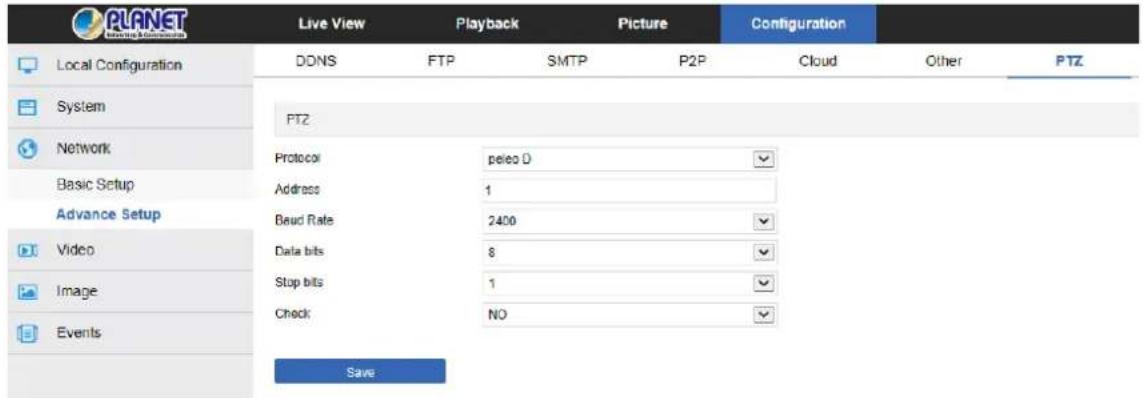
Figure 8-19

- Only PTZ-enabled cameras have a PTZ interface. Please refer to the actual camera function.
IPEYE
In the main interface, click "Configuration →Network → Advanced Setup → IPEYE" to enter the IPEYE interface. After IPEYE is enabled, you can add the device to the IPEYE account at https://www.ipeye.ru/ View IP Camera real-time audio / video, as shown in
Figure 8-20 Φ.
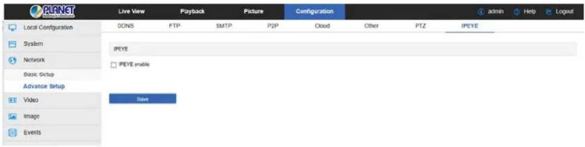
Figure 8-20 ①
The steps to monitor the audio and video in real time at https://www.ipeye.ru/ are as follows:
Step 1: Enter IPEYE interface, enable IPEYE enable, refresh the interface, and the interface displays IPEYE Client address as shown in Figure 8-20 2.
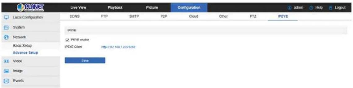
Figure 8-20
Step 2: Log in to IPEYE Client "http://192.168.1.205:8282", and enter the device username, password, IP camera user and password. Click "Confirm" when a device is added, as shown in Figure 8-20 ③.
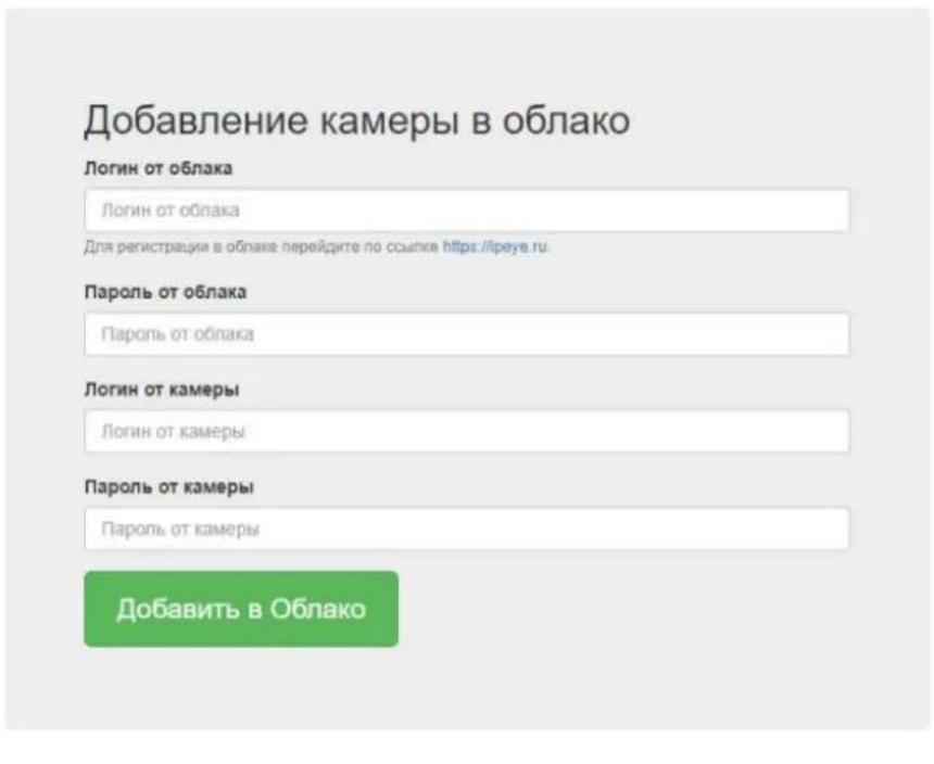
© IPEYE Company, Inc.
Figure 8-20 ③
Step 3: Log in to "https://www.ipeye.ru/" and enter the IPEYE device list to view the newly added device named as "cloud_xxxxx". Click the Play button to view the device real-time
monitoring video. The list of IPEYE devices is shown in Figure 8-20 4.
![IP EYE Device List Add content Edit View account sp(x1-x2) Language of the website Device List Name Group Text Audio Video Options Action 100.000 No group Electronic8 0 mm 5 [ ] [ ] [ ] [ ] [ ] [ ] [ ] [ ] [ ] [ ] [ ] [ ] [ ] [ ] [ ] [ ] [ ] [ ] [ ] [ ] [ ] [ ] [ ] [ ] [ ] [ ] [ ] [ ] [ ] [ ] [ ] [ ] [ ] [ ] 100.000 No group Electronic8 0 mm 5 [ ] [ ] [ ] [ ] [ ] [ ] [ ] [ ] [ ] [ ] [ ] [ ] [ ] [ ] [ ] [ ] [ ] [ ] [ ] [ ] [ ] [ ] [ ] [ ] [ ] 100.000 No group Electronic8 0 mm 5 [ ] [ ],[ ][ ][ ][ ][ ][ ][ ][ ][ ][ ][ ][ ][ ][ ][ ][ ][ ][ ][ ][ ][ ][ ][ ][ ][ ][ ][ ][ ][ ][ ][ ][ ][ ][ ][ ][ ][ ][ ][ ][ ][ ][ ][ ][ ][ ][ ][ ][ ][ ][ ][ ][ ][ ][ ][ ][ ][ ][ ][ ][ ][ ][ ][ ][ ][ ][ ][ ][ ][ ][ ][ ][ ][ ][ ][ ][ ][ ][ ][ ][ ][ ][ ][ ][ ][ ][ ][ ][ ][ ][ ][ ][ ][ ][ ][ ][ ][ ][ ][ ][ ][ ] Search by name Box AE [ ].](/content/2026/05/1044031/images/e6981af68a4e57d191a65bb3f8dedc8bba78b52e580347f66d49b99a4e0e0619.jpg)
Figure 8-20 ④

- Some cameras do not support the IPEYE function. The specific interface is subject to the actual product.
8.4 Video
In the main interface, click "Configuration → Video" to enter the video and audio configuration interface, where you can set the device video, audio and other functions.
8.4.1 Video
In the main interface click "configuration → video → video" into the video configuration interface, where you can set the IP Camera device name, stream type, encoding and other video parameters, as shown in Figure 8-21:
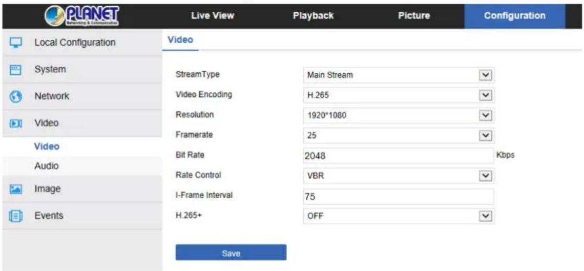
Figure 8-21
【Stream Type】 Here Single/Third available.
【Profile】 Default is the Main Profile; you can select Baseline Profile or High Profile.
【Video Encoding】Switch the encoding method in the drop-down menu.
【Resolution】Switch the output resolution in the drop-down menu.
【Framerate】 Set the frame rate of the current output video of the device.
【Bit Rate】Supports 64-12000kbps. The higher the bit rate goes, the better the video quality will be, but it occupies the greater network bandwidth and the greater the pressure transmission.
【Rate Control】 Switch the code rate output mode in the drop-down menu -- fixed rate and variable rate.
【I-Frame Interval】IP Camera acquisition key frame interval, can be set 1-5s.
【H265+/H264+】Turn on/off the camera H265+/H264+.
【Watermark】Turn on / off. It can prevent the video from being tampered after it is turned on. After setting the "watermark name", use our "HSPlayer" player to query the video information with watermark.
【Watermark name】Enter a watermark name.
| Note | Different IP Camera -- device stream type, encoding, frame rate and other information in the drop-down menu options are also different. When the frame rate is set too low, it will cause video lag. Please be careful. The higher the bit rate is, the greater the current network bandwidth and the greater the transmission pressure will be. Only cameras that support the H264+/H265+ function displaying H264+/H265+ on/off items on the video interface. It takes 30-60 seconds for the camera to turn the H265+/H264+ on or off. Please be patient. The IP camera SD card supports the watermark function during normal video recording. |
8.4.2 Audio
In the main interface, click "Configuration → Video → Audio" to enter the audio
configuration interface, where you can set the device audio input mode. Select the audio code and set the input volume, as shown in Figure 8-22:
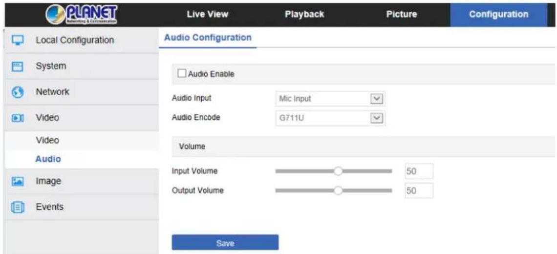
Figure 8-22
【Audio Enable】Turn on / off device audio input.
【Audio Input】Select the audio input method.
In the main interface, click "Configuration → Image" to enter the image configuration interface, where you can set the device image and OSD text and other information.
8.5.1 Image
In the main interface, click "Configuration → Image → Image" to enter the image
configuration interface, where you can adjust the related image parameters such as Image Adjustment, Exposure Settings, Focus, BackLight Settings, Day and night switch, White Balance, Video Adjustment, Image Enhancement, Defog Mode and Distortion as shown in Figure 8-23:
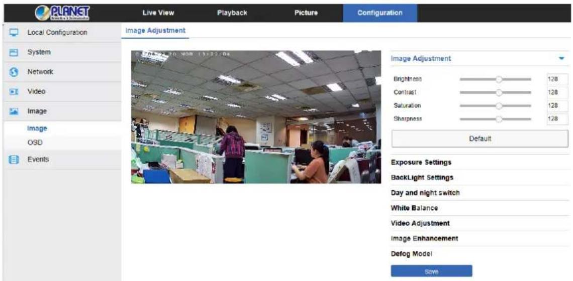
Figure 8-23
【Image Adjustment】 You can input the value manually to set brightness, contrast,
saturation and sharpness. These parameters are set according to the actual environment. The scope of valid values is from 0 to 255. You can drag the slider to set, and the default value is 128, as shown in Figure 8-24:
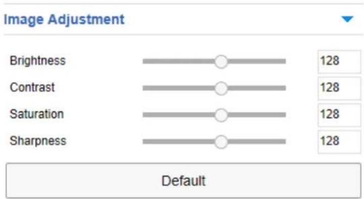
Figure 8-24
【Exposure Settings】The default is automatic exposure. To meet the actual need, switch
to the manual exposure mode by selecting "Manual". When the Exposure Time and Gain Control is activated, click "Save", as shown in Figure 8-25:
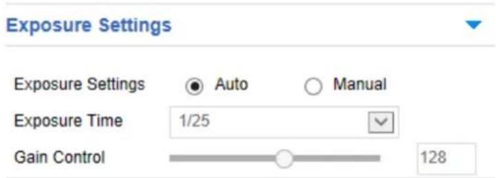
Figure 8-25
【Focus】 It is used to select the focus mode of the zoom camera. The default is
"semi-autofocus", and "Automatic" focus and "Manual" focus can also be selected, as shown in Figure 8-26:
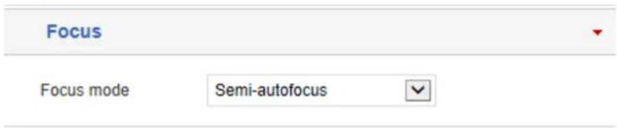
Figure 8-26
【Backlight Settings】 It is used to set backlight compensation and strong light
suppression. The default is off. It can be turned on manually, and the backlight, strong light suppression intensity and dark area boost strength can be set, as shown in Figure 8-27 below.
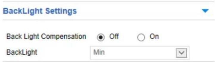
Figure 8-27
【Day and night switch】By default, the light mode is automatic where sensitivity is 3, and filter time is 3 seconds. When the light mode is manual, light brightness is 100, as shown in Figure 8-28 . When it is "Automatic", the device will turn on the light according to the actual environment. The user can switch the mode to "Daytime ", "Night" and "Time" according to the actual environment of the site, and switch the sensitivity and filter time of the device according to the mode you want.
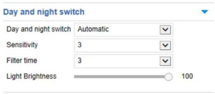
Figure 8-28 ①
- When the mode is "Time", you can set the Dawn time and the Dark time (the start and end time) and the light brightness, as shown in Figure 8-28 0:
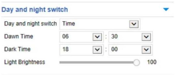
Figure 8-28 ☉
- When the mode is "Daytime", the device monitor video is lit to have the daytime effect. - When the mode is "Night", the device monitor video is added to the night effect.
Filtering time: It is used to prevent the ambient light from getting better and the light is frequently turned on and off, and the filtering time is set. During this time period, the camera is not disturbed by ambient light.
Light brightness: It is used to adjust the brightness of the light, and the adjustable range is 0-100.
【White Balance】By default, it is auto. Manually, it is adjustable be it Fluorescent Lamp, Incandescent, Warm Light, or Natural Light, as shown in Figure 8-29:
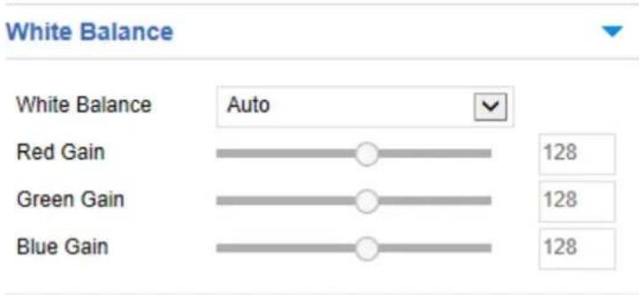
Figure 8-29
Manual white balance: It supports Red, Green, and Blue gain adjustments. You can adjust the range (0-255). When it is done, click "Save".
【Video Adjustment】 Here you can turn on and set 2D or 3D digital noise reduction, as shown in Figure 8-30.
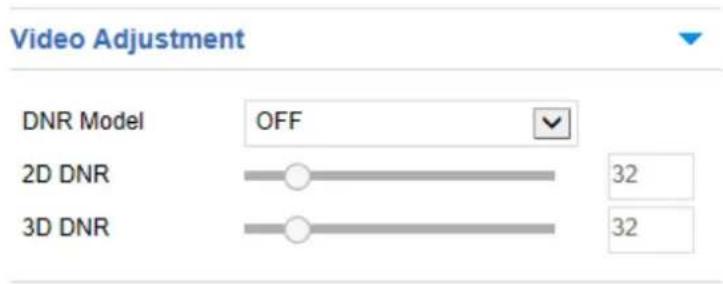
Figure 8-30
【Image Enhancement】Includes flicker control, wide dynamic switch and HDR, as shown in Figure 8-31.
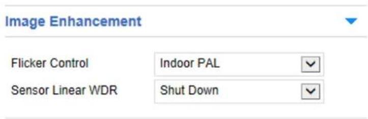
Figure 8-31
Flicker Control: The flash mode is selected according to the camera installation environment and the flicker standard. The default setting is PAL (50HZ) shipment.
Sensor Linear WDR : The default is Shut Down. You can switch in the drop-down menu
Automatic, Weak, Moderate, Strong or Super.
【Defog Mode】Used to set the defog mode and strength, as shown in Figure 8-32.
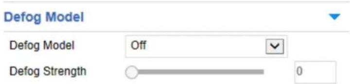
Figure 8-32
Defog Mode: The default is off. You can choose from the drop-down menu On or Auto.
Defog Strength: The default is 0. When the fog mode is open, you can set the fog strength, and a value range of 0-255.
8.5.2 OSD
The OSD is information displayed on the real-time monitoring screen. The name, date, and day of the IP Camera can be displayed on the monitor screen.
In the main interface, click "Configuration → Image → OSD" to enter the OSD
configuration interface, where you can set the preview interface to display menu time, OSD text and other information, as shown in Figure 8-33:
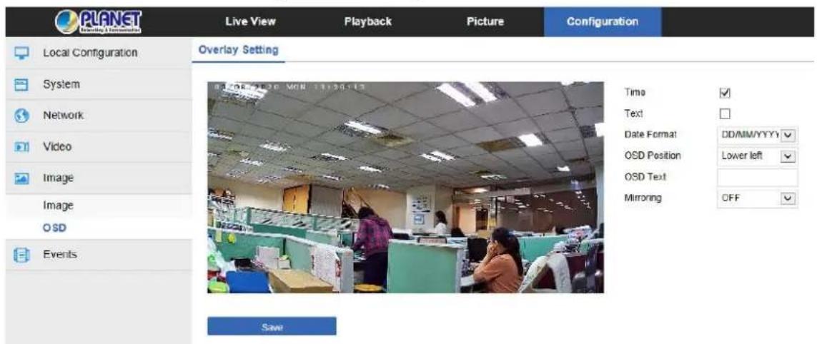
Figure 8-33
【Time】Turn on / off the preview interface time display.
【Text】 Turn on / off the preview interface OSD text display.
【Date Format】 Set the preview interface to display the date format, default day / month / year, switchable month / day / year and year / month / day options.
【OSD Position】Set the preview interface to display the time or OSD text position, the default is the Top_Left, you can switch the Bottom_Left.
【OSD Text】Enter the preview interface to display text information, such as hall elevator, hall door and other equipment location information.
【Mirroring】The default is OFF. You can switch to VERTICAL, HORIZONTAL, or BOTH, when the device video image is reversed, through the menu to flip the image.
【Corridor Pattern】The default is off. In the corridor mode, you can choose to preview the interface rotated 90 degrees and 270 degrees.
8.6 Events
In the main interface, click "Configuration → Events" to enter the event configuration interface, including common events and smart events.
8.6.1 Ordinary Event
In the Ordinary event interface, you can set the device's motion detection, privacy mask, video tampering, alarm input, exception and other events.
Motion Detection
The motion detection function is used to detect whether there is a moving object in a certain area within a certain period of time. When there is a moving object, the IP camera will alarm according to the setting.
In the main interface click on the "Configuration → Events → Motion Detection" to enter the motion detection settings interface, where you can set the motion detection alarm area, arming time, linkage mode and other related parameters, as shown in Figure 8-34.
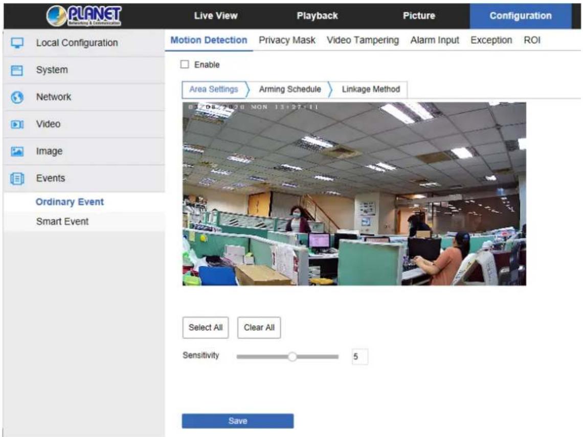
Figure 8-34
【Enable】Turn on / off device motion detection alarm.
Area Settings: Select the area to set the motion detection sensitivity.
【Select All】Motion detection range is to monitor all of the areas, which consist of 396 (22 x 18) small squares.
【Manually draw the alarm area】Move the mouse to the preview screen and click the left mouse button to select the range of motion detection. Release the left mouse button to complete the alarm area selection. A camera can select multiple motion detection zones at the same time.
【Clear All】 Clearing all the motion detection areas that were selected.
【Sensitivity】The default is 5, but the range of 0-10 can be chosen. The greater the value is, the more sensitive the equipment alarm will become.
Arming Schedule : As shown in Figure 8-35 below, you can view, edit, and delete the arming time of motion detection. The default is to arm the alarm 24 hours a day. You can adjust the arming time as follows:
Method 1: Click the arming time period, manually fill in the start time and end time, set up and click Save. If you need to delete the time period, click the "Delete" button and
then reset the time period.
- Method 2: Click the arming time period, two arrows will be displayed at both ends of the time period. Move the adjustment arrow left or right to adjust the arming time.
- You can set up more than one time period for up to 8 time periods.
- After the day of deployment time is set, if the other time also needs to be set at the
same arming time, click the right side of the timeline " ☐" copy button; in the "copy to" interface, check the "Select All" or a day, and then Click "OK".
- After setting, click "Save" to complete the setting of the arming time.
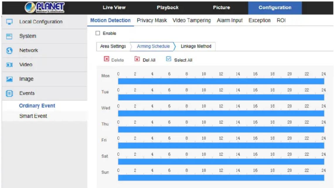
Figure 8-35
- When the arming time is set, there can be no overlap between any two time periods.
Linkage Method: When the motion detection is to open the alarm linkage, there are a variety of alarm linkages, including conventional linkage and linkage alarm output, as shown in Figure 8-36:
【General Linkage】 Includes uploading SMTP, uploading FTP, uploading cloud and SD card recording.
【Upload Via SMTP】Select and the system is configured with SMTP. The alarm information will be sent to the SMTP recipient mailbox.
【Upload Via FTP】 Select and the system is configured with the FTP server; it will send the alarm information to the FTP server.
【Upload Via Cloud】 Select and the system is configured with the cloud server. It will send the alarm information to the cloud account.
【Record Via SDcard】Select and configure the system video; the alarm will record the alarm video to the IP Camera SD card.
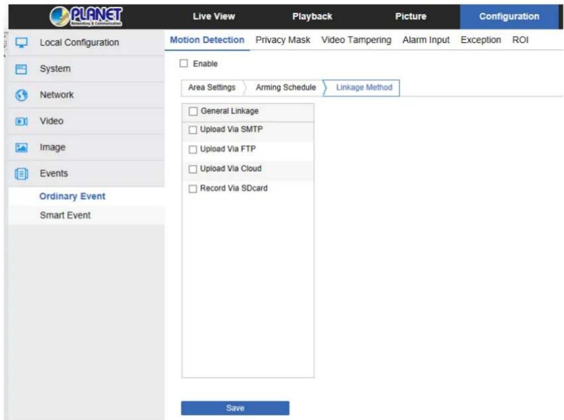
Figure 8-36
Open the "General Linkage", "Upload Via SMTP", "Upload Via FTP", "Upload Via Cloud", and "Record via SDcard" function, when the device motion detection alarm, the linkage corresponding way to inform the user.
② Privacy Mask
Privacy occlusion is a privacy protection feature that blocks the privacy of the surveillance screen from being viewed and recorded.
In the main interface, click "Configuration → Event → Privacy Mask" to enter the privacy mask settings interface, as shown in Figure 8-37.
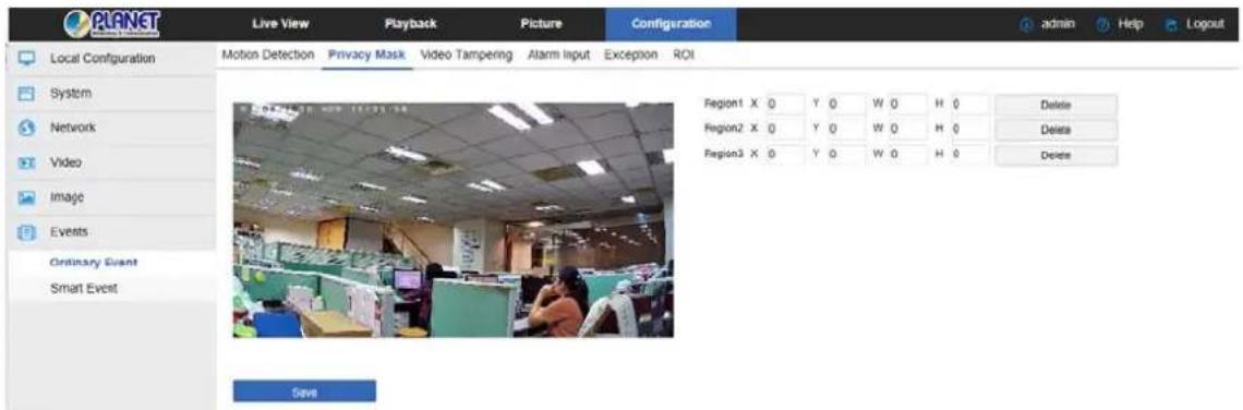
Figure 8-37
Here you can choose up to 3 occlusion areas. Hold down the left mouse button and drag to select the area in the area. Region 1, Region 2 and Region 3 below will show the corresponding coordinates, width, and height of the region. If you want to delete a region, click on the corresponding "Delete" button. Click on the "Save" after completing the setting.
③ Video Tampering
The occlusion alarm function is used to detect whether a monitoring area is blocked by human factors and other factors during a certain period of time. When the area of the device is blocked, the IP camera will alarm according to the settings. When the occlusion alarm is generated, the occlusion alarm cause can be quickly discharged and the monitoring screen can be restored.
In the main interface click on the "configuration Events Video Tampering" to enter the video tampering settings interface, as shown in Figure 8-38:
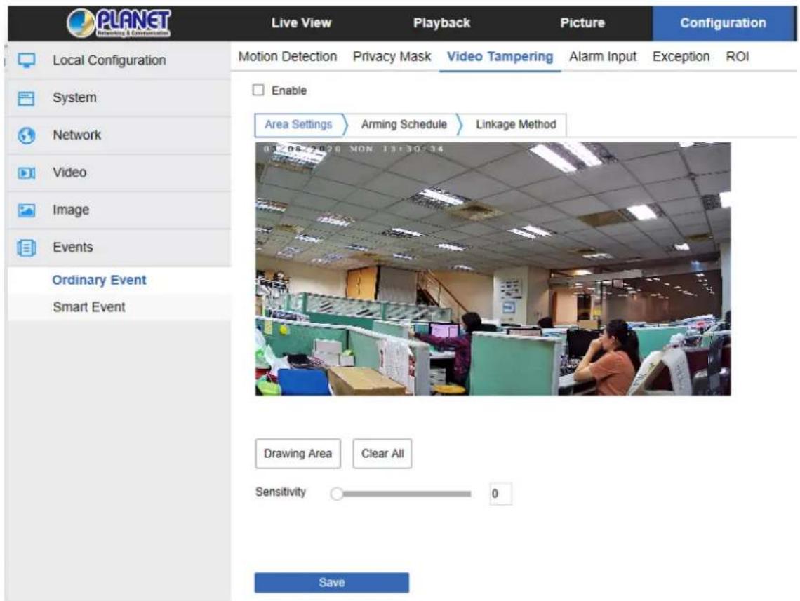
Figure 8-38
【Enable】Turn on / off device video tampering alarm.
Area Settings: Select the area to set the video tampering sensitivity.
【Drawing Area】Move the mouse to the preview screen and click the left mouse button to select the range of motion detection and release the left mouse button. Click “Stop Drawing” to complete the alarm area selection.
【Clear All】 Clearing all the video tempering areas that were selected.
【Sensitivity】The default is 0. The range of 0-2 is manually selectable. The greater the value is, the more sensitive the equipment alarm will be.
Arming Schedule : As shown in Figure 8-39, you can view, edit, and delete the arming time of the video tampering. The default is to arm the alarm 24 hours a day. You can adjust the arming time as follows:
Method 1: Click the arming time period and manually fill in the start time and end time, set up and click Save. If you need to delete the time period, click the "Delete" button and then reset the time period.
Method 2: Click the arming time period; two arrows will be displayed at both ends of the time period. Move the adjustment arrow left or right to adjust the arming time.
- You can set up more than one time period for up to 8 time periods.
- After the day of deployment time is set, if the other time is also needed to set the same arming time, click the right side of the timeline " ☐ " copy button. In the "copy to" interface, check the "Select All" or a day, and then Click "OK".
- After setting, click "Save" to complete the setting of the arming time.
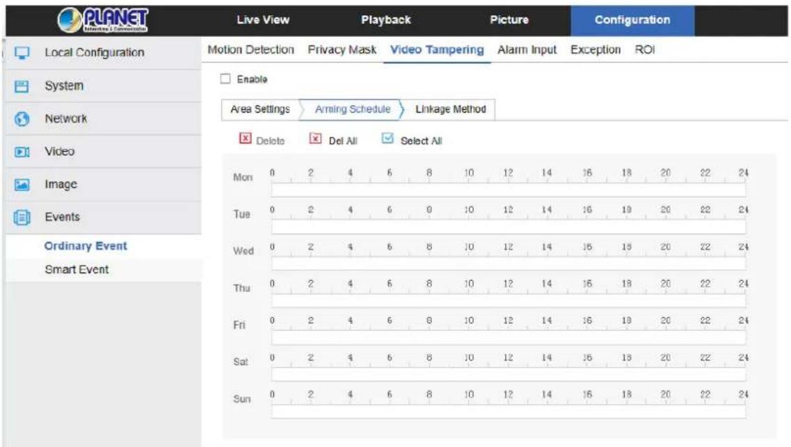
Figure 8-39

- When the arming time is set, there can be no overlap between any two time periods.
Linkage Method: Alarm linkage mode upload SMTP and upload FTP regular linkage, as shown in Figure 8-40:
【General Linkage】 Including uploading SMTP and uploading FTP.
【Upload Via SMTP】Select and the system is configured with SMTP, and the alarm information will be sent to the SMTP recipient mailbox.
【Upload Via FTP】Select and the system is configured with the FTP server, and will send the alarm information to the FTP server.
【Upload Via Cloud】Select and the system is configured with the Cloud server, and will send the alarm information to the Cloud server.
【Record Via SDcard】Select and the system is configured with the SDcard record, and will be recorded to the IP Camera SD card during the video tampering alarm.
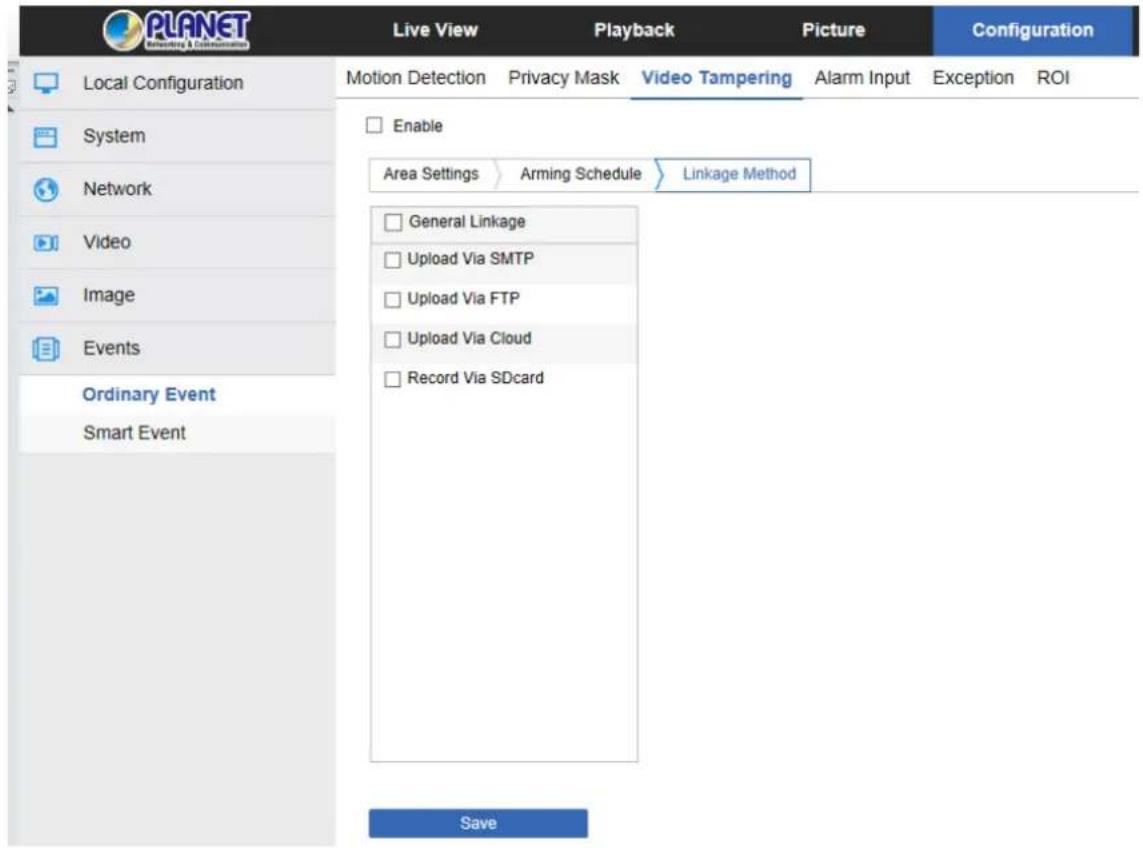
Figure 8-40
Here to open the "General linkage", "Upload via FTP", "Upload via SMTP", "Upload via Cloud", "Record via SDcard" function, when the device settings area is blocked and alarm, the corresponding way to inform the user.
④ Alarm Input
In the main interface click on the "configuration → Events → Alarm Input" to enter the Alarming Schedule settings interface.
Arming Schedule : As shown in Figure 8-41, you can view, edit, and delete the arming time of the alarm input. The default is to arm the alarm 24 hours a day. You can adjust the arming time as follows:
Method 1: Click the arming time period, manually fill in the start time and end time, set up and click "Save". If you need to delete the time period, click the "Delete" button and then reset the time period.
Method 2: Click the arming time period, two arrows will be displayed at both ends of the time period. Move the adjustment arrow left or right to adjust the arming time.
- You can set up more than one time period for up to 8 time periods.
After the day of deployment time is set, if the other time is also needed to set the
same arming time, click the right side of the timeline " ☐ " copy button. In the "copy
to" interface, check the "Select All" or a day, and then Click "OK".
- After setting, click "Save" to complete the setting of the arming time.
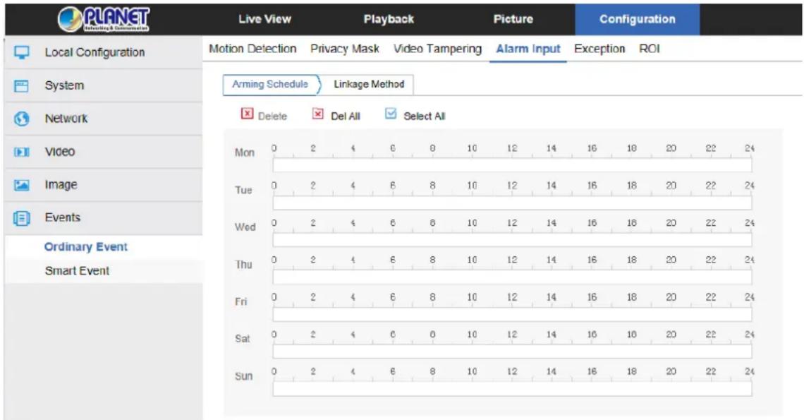
Figure 8-41
Linkage mode settings: The alarm linkage mode has general linkage and linkage alarm output, as shown in Figure 8-42.
【General Linkage】 Including upload SMTP and upload FTP.
【Upload Via SMTP】Select and the system is configured with SMTP, and the alarm information will be sent to the SMTP recipient mailbox.
【Upload Via FTP】Select and the system is configured with the FTP server, and will send the alarm information to the FTP server.
【Linkage Alarm Output】 Including IO output.
【IO Output】 Be enabled and the device IO port is connected to the output alarm device. When there is alarm input, the alarm device is connected with IO port that will make the corresponding alarm activate.
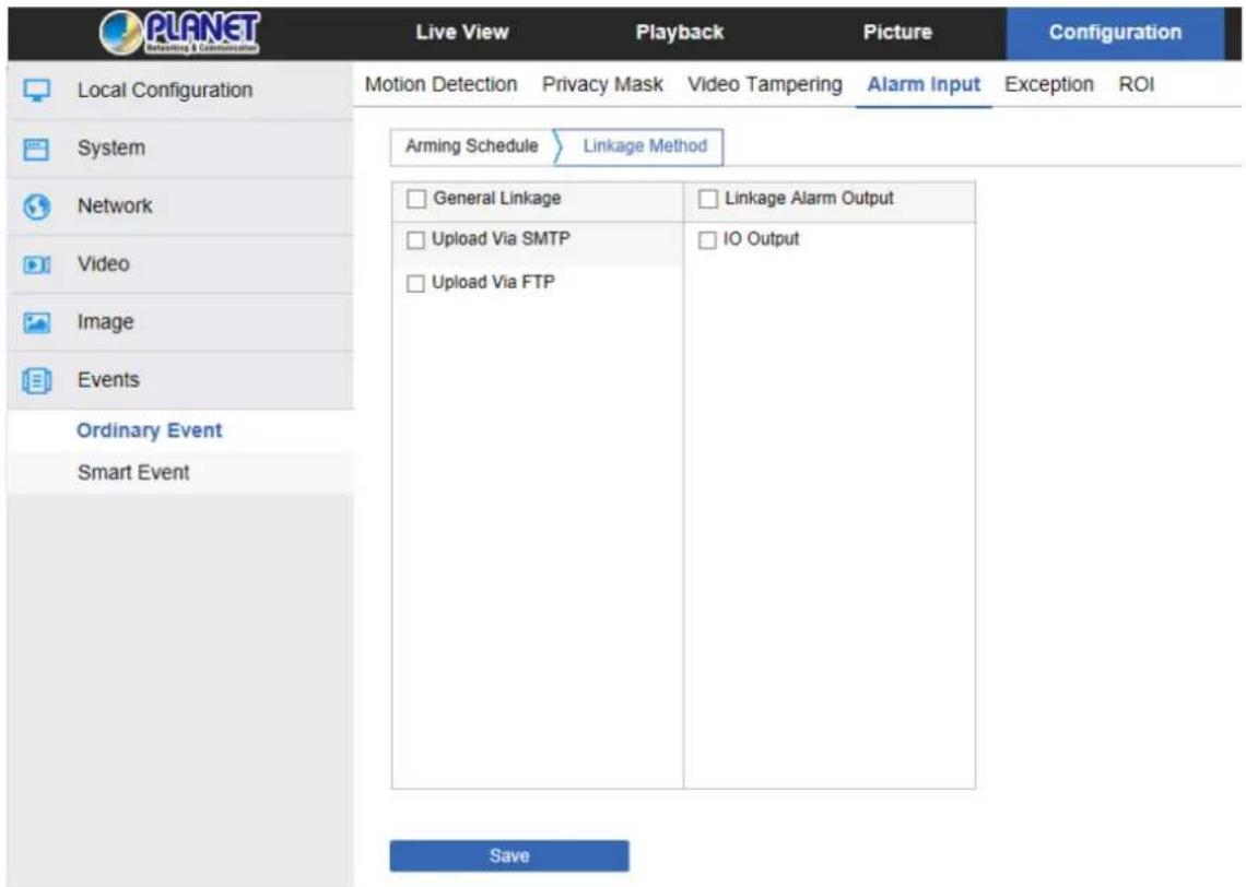
Figure 8-42
⑤ Exception
In the main interface, click "Configuration → Events → Exception" to enter the exception settings interface, as shown in Figure 8-43.
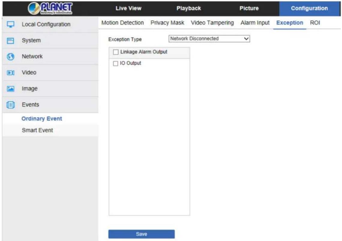
Figure 8-43
Set the "Network Disconnected" and "IP Address Conflicted" alarms here, and set the alarm output mode. Click on the "Save" after completing the settings.
6 ROI
ROI set the "Relative QP value" or "QP absolute value" functions for the region of interest. Up to three "fixed areas" can be set. On the main interface, click "Configuration → Events → ROI" to enter the ROI setting interface, as shown in Figure 8-44.
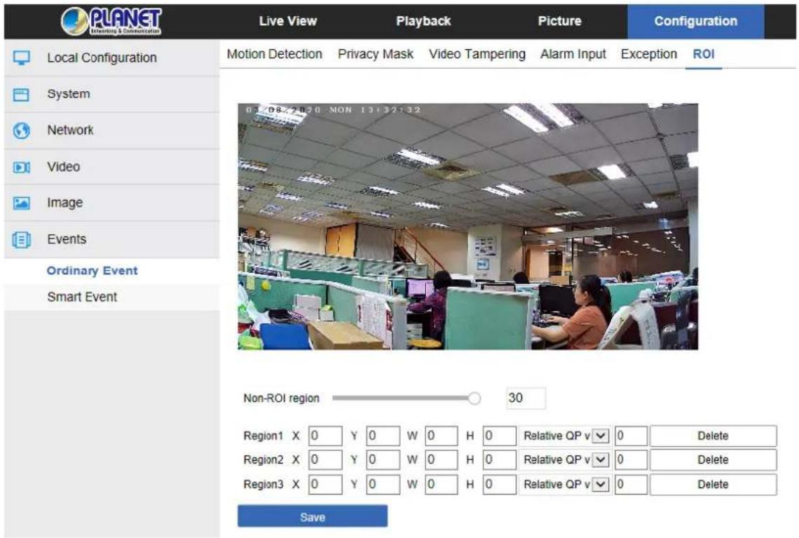
Figure 8-44
The specific steps of the ROI are as follows:
Step 1: 【Region Settings】Move the mouse to the preview screen, hold down the left mouse button to select the ROI area range, and release the left mouse button to complete the area drawing. You can also enter the X, Y, W, and H corresponding positions in the corresponding area to set the area.
Step 2: 【Set "Relative QP value" or "Absolute QP value"] Select "Relative QP value"
or "Absolute QP value" in the corresponding area position and enter the corresponding value.
Step 3: Slide the scroll bar to set the frame rate of the Non-ROI region, and click "Save" to complete the ROI setting.

- The ROI function depends on the specific model, and the ROI function is only supported under the H.264 or H.265 code. Other codes do not support the ROI function at this time.
- The ROI configuration is more effective when using a lower non-ROI frame rate setting.
- Click 【Delete】 in the corresponding setting area to delete the corresponding ROI area.
8.6.2 Smart Event
Smart event interface is to set face recognition, regional intrusion detection, cross border detection, wandering detection and personnel aggregation detection.
① Face Recognition
The face recognition function is used to detect the face appearing in the face database in the monitoring screen, and to perform frame selection tracking on the monitoring interface. The specific steps are as follows:
Step 1: In the main interface click on the "Configuration → Events → Smart Event" to enter the Face Recognition settings interface, as shown in Figure 8-45.
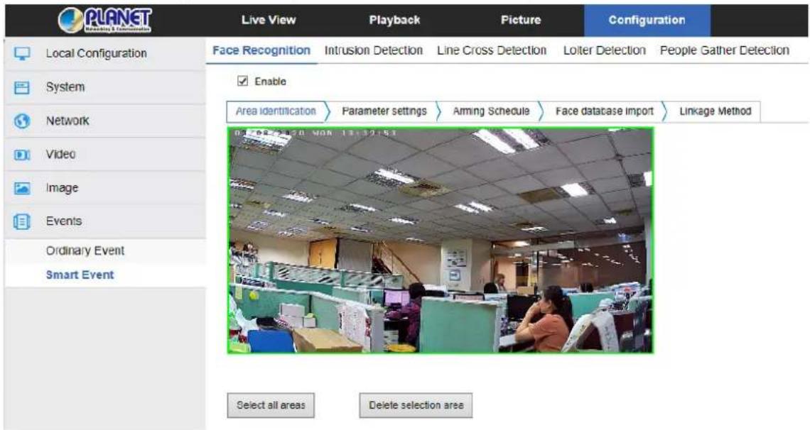
Figure 8-45
Step 2: Check "Enable" to enable face recognition.
Step 3: To set the arming area, move the mouse to the preview screen, hold down the left mouse button to select the area of the face recognition, and release the left mouse button to complete the area drawing.
【Select all areas】is used to set all areas under the monitor screen as the guard area.
【Delete Selection Area】is used to delete the selected alert area.
Step 4: To set related parameters, set the minimum face recognition pixel, open the face tracking frame, turn on the OSD overlay, and set the face contrast recognition threshold.
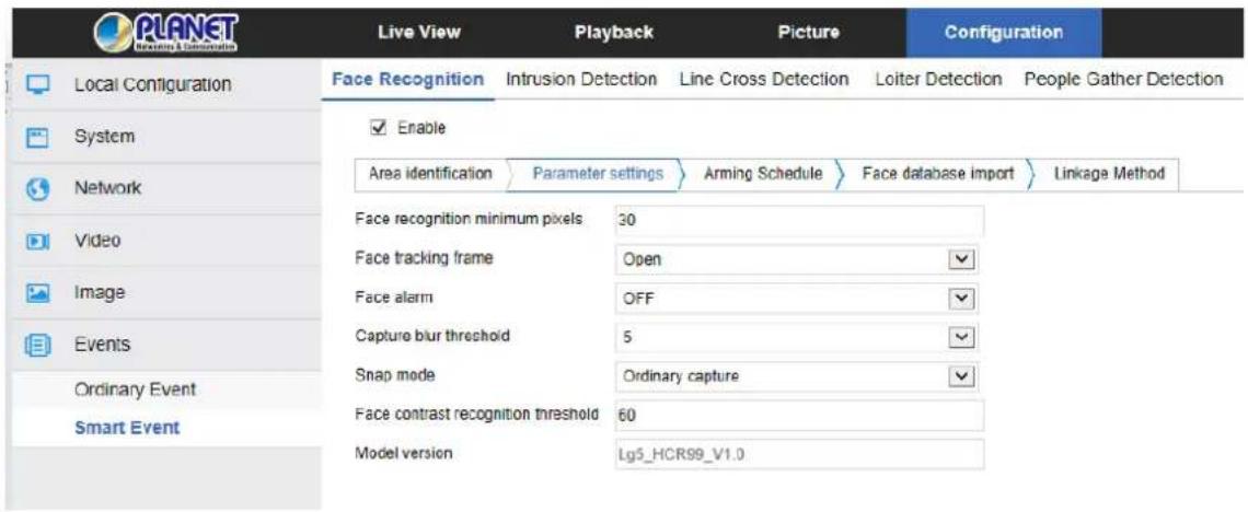
Figure 8-46
【Face recognition minimum pixels】It means that a face which is larger than the pixel in the monitor screen will be recognized.
【Face tracking frame】After being turned on, the monitor screen recognizes that the face will be selected by the red frame, and the frame will move as the face moves to realize face tracking.
【Face alarm】After being turned on, the device will alarm when it detects a face according to the capture mode, and the relevant information can be found in the log.
【Capture blur threshold】Sets the capture face sharpness value. When the device recognizes that the face reaches the resolution, the device performs a snap action.
【Snap mode】 It consists of Ordinary capture, Face library capture, and Non-face library capture. The device captures according to the capture mode.
【Face contrast recognition threshold】The smaller the threshold is set, the lower the comparison between the face and the face database is. If the threshold is 20, there are several similarities between tracking the face and the face database. The OSD displays the comparison result. Otherwise, the setting threshold is larger. The higher the requirement is to track the face and face database. If the threshold is set to 100, the tracking face must be 100% similar to a picture in the face database to be recognized and displayed on the OSD.
Step 5: Arming Schedule, as shown in Figure 8-47. You can view, edit, and delete the arming time of the face recognition. The default is to arm the alarm 24 hours a day. You can adjust the arming time as follows:
Method 1: Click the arming time period, manually fill in the start time and end time, set up and click Save. If you need to delete the time period, click the "Delete" button and then reset the time period.
- Method 2: Click the time of deployment. The time period will display two circles at
both ends. Move the mouse to the circle to show the left and right direction of the adjustment arrow. And move the adjustment arrow to adjust the arming time.
- You can set up more than one time period for up to 8 time periods.
- After the day of deployment time is set, if the other time is also needed to set the
same arming time, click the right side of the timeline "☐" copy button. In the "copy to" interface, check the "Select All" or a day, and then Click "OK".
- After setting, click "Save" to complete the setting of the arming time.
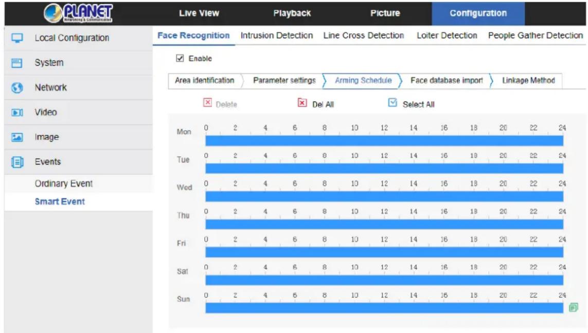
Figure 8-47
- When the arming time is set, there can be no overlap between any two time periods.
Step 6: Face database import, as shown in Figure 8-48: Click “Face database import” →
select the import method "Append" or "Overwrite" according to needs → click "Browse"
to select the face library folder → click "Import" ->"OK", waiting for the import to successfully import the file. It is recommended to keep power on during the import process.
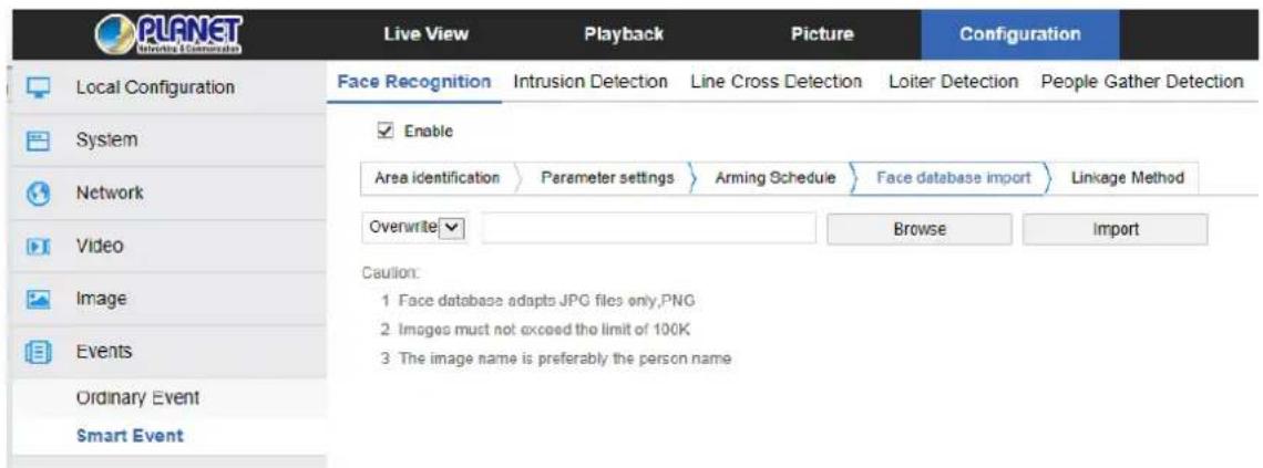
Figure 8-48

● Face database adapts to JPG files only, PNG.
● Image must not exceed the limit of 200K.
● The image name is preferably the person name.
Step 7: Set the linkage method as needed.
【Linkage Method】 refers to the response made by the device when an alarm event
occurs. The linkage includes "General Linkage" and "Capture link".
② Intrusion Detection
The area intrusion detection is used to detect whether an object enters the set area in the video setting area, and the alarm is linked according to the judgment result. The specific steps are as follows:
Step 1: In the main interface click on the "Configuration → Events → Smart Event→
Intrusion Detection" to enter the Intrusion Detection settings interface, as shown in Figure 8-49.
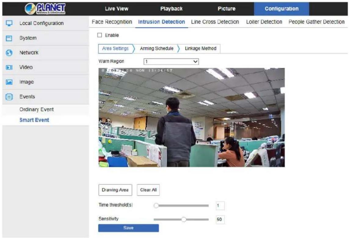
Figure 8-49
Step 2: Check "Enable" to enable intrusion detection.
Step 3: Select "Warn Region": The system supports setting up to 4 warn regions. After selecting a warn region, you need to make the following settings. After setting, please click "Save" below.
【Drawing Area】Click "Drawing Area" and move the mouse to the preview screen.
Click the left mouse button and draw the endpoint of the quadrilateral guard area, and then click the preview interface to complete the area drawing.
【Clear All】 Used to delete the selected alert area.
【Time threshold(s)】 Indicates that the target enters the alert zone and continues to stay for this time to generate an alarm. If set to 5s, the target intrusion area will trigger an alarm after 5s.
【Sensitivity】Used to set the sensitivity of detected area intrusion. The default is 50.
Drag the progress bar or enter the value directly in the value box to modify the sensitivity. The greater the sensitivity is, the easier it is to trigger an alarm.
Step 4: When you need to set other Warn Regions, repeat step 3 to complete the setup.
Step 5: Arming Schedule, as shown in Figure 8-50. You can view, edit, and delete the arming time of the intrusion detection. The default is to arm the alarm 24 hours a day. You can adjust the arming time as follows:
Method 1: Click the arming time period, manually fill in the start time and end time, set up and click Save. If you need to delete the time period, click the "Delete" button and then reset the time period.
Method 2: Click the time of deployment. The time period will display two circles at both ends. Move the mouse to the circle to show the left and right direction of the adjustment arrow, and move the adjustment arrow to adjust the arming time.
- You can set up more than one time period for up to 8 time periods.
- After the day of deployment time is set, if the other time is also needed to set the
same arming time, click the right side of the timeline "☐" copy button. In the "copy to" interface, check the "Select All" or a day, then Click "OK".
- After setting, click "Save" to complete the setting of the arming time.
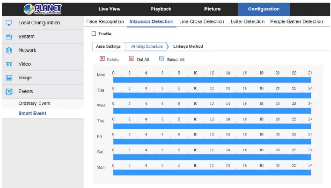
Figure 8-50

- When the arming time is set, there can be no overlap between any two time periods.
Step 6: Set the linkage method as needed.
【Linkage Method】 refers to the response made by the device when an alarm event occurs. The linkage includes “General Linkage”, “Upload Via SMTP” and “Upload Via FTP”
③ Line Cross Detection
The line cross detection function is used to detect whether there is an object in the video that crosses the set warning surface, and the alarm is linked according to the judgment result. The specific steps are as follows:
Step 1: In the main interface click on the "Configuration → Events → Smart Event →
Line Cross Detection" to enter the Line Cross Detection settings interface, as shown in Figure 8-51.
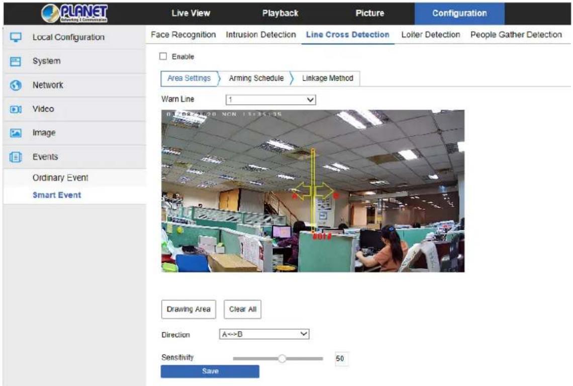
Figure 8-51
Step 2: Check "Enable" to enable intrusion detection.
Step 3: Select "Warn Line": The system supports setting up to 4 warn lines. After selecting a warn line, you need to make the following settings. After setting, please click "Save" below.
【Warn Line】Click "Drawing Area" and a line segment with an arrow will appear on the screen. Click on the line segment. Click and drag one of the endpoints to modify the length of the line segment or click and drag the position of the line segment with the arrow in the picture to complete the drawing of a warning surface.
【Clear All】Used to delete the selected alert area.
【Direction】There are three options: “A<->B”, “A->B”, and “B->A”, indicating the
direction in which the object crosses the interface to trigger an alarm. "A->B" means that
the alarm will be triggered when the object crosses from A to B; "B->A" means that the
alarm will be triggered when the object crosses from B to A; "A<->B" means that the object crosses from A to B, or from B to B. The alarm is triggered, that is, the alarm is triggered in both directions.
【Sensitivity】 Used to set the sensitivity of detected area intrusion. The default is 50.
Drag the progress bar or enter the value directly in the value box to modify the sensitivity. The greater the sensitivity is, the easier it is to trigger an alarm.
Step 4: When you need to set other Warn Lines, repeat step 3 to complete the setup.
Step 5: Arming Schedule, as shown in Figure 8-52. You can view, edit, and delete the arming time of the Line Cross detection. The default is to arm the alarm 24 hours a day.
You can adjust the arming time as follows:
Method 1: Click the arming time period, manually fill in the start time and end time, set up and click Save. If you need to delete the time period, click the "Delete" button and then reset the time period.
Method 2: Click the time of deployment. The time period will display two circles at both ends. Move the mouse to the circle to show the left and right direction of the adjustment arrow, and move the adjustment arrow to adjust the arming time.
- You can set up more than one time period for up to 8 time periods.
- After the day of deployment time is set, if the other time is also needed to set the
same arming time, click the right side of the timeline "☐" copy button. In the "copy to" interface, check the "Select All" or a day, then Click "OK".
- After setting, click "Save" to complete the setting of the arming time.

Figure 8-52

- When the arming time is set, there can be no overlap between any two time periods.
Step 6: Set the linkage method as needed.
【Linkage Method】 refers to the response made by the device when an alarm event
occurs. The linkage includes "General Linkage", "Upload Via SMTP" and "Upload Via FTP".
④ Loitering Detection
The loitering detection function is used to detect the target that stays within the set area for more than the set time threshold, and then alarms according to the judgment result. The specific steps are as follows:
Step 1: In the main interface click on the "Configuration → Events → Smart Event → Loiter Detection" to enter the Loitering Detection settings interface, as shown in Figure 8-56.3
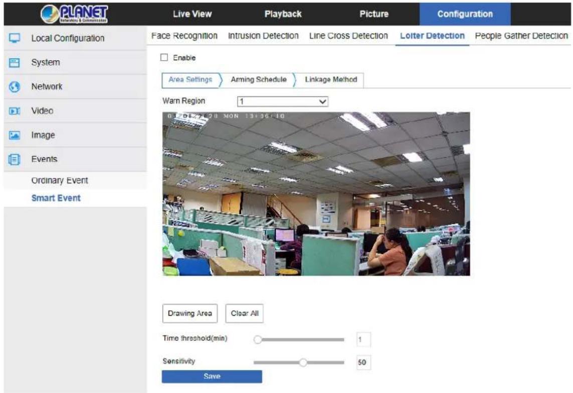
Figure 8-53
Step 2: Check "Enable" to enable intrusion detection.
Step 3: Select "Warn Region": The system supports setting up to 4 warn regions. After selecting a warn region, you need to make the following settings. After setting, please click
"Save" below.
【Drawing Area】Click "Drawing Area" and move the mouse to the preview screen.
Click the left mouse button and draw the endpoint of the quadrilateral guard area, and then click the preview interface to complete the area drawing.
【Clear All】Used to delete the selected alert area.
【Time threshold(min)】 Indicates that the target generates an alarm after continuous
movement in the detection area. The larger the time threshold is, the longer the target continues to move in the detection area to trigger an alarm.
【Sensitivity】 Used to set the sensitivity of detected area intrusion. The default is 50.
Drag the progress bar or enter the value directly in the value box to modify the sensitivity.
The greater the sensitivity is, the easier it is to trigger an alarm.
Step 4: When you need to set other Warn Region, repeat step 3 to complete the setup.
Step 5: Arming Schedule, as shown in Figure 8-54. You can view, edit, and delete the arming time of the Loitering detection. The default is to arm the alarm 24 hours a day. You can adjust the arming time as follows:
- Method 1: Click the arming time period, manually fill in the start time and end time, set up and click Save. If you need to delete the time period, click the "Delete" button and then reset the time period.
- Method 2: Click the time of deployment. The time period will display two circles at both ends. Move the mouse to the circle to show the left and right direction of the adjustment arrow, and move the adjustment arrow to adjust the arming time.
- You can set up more than one time period for up to 8 time periods.
After the day of deployment time is set, if the other time is also needed to set the same arming time, click the right side of the timeline "☐" copy button. In the "copy to" interface, check the "Select All" or a day, then Click "OK".
- After setting, click "Save" to complete the setting of the arming time.
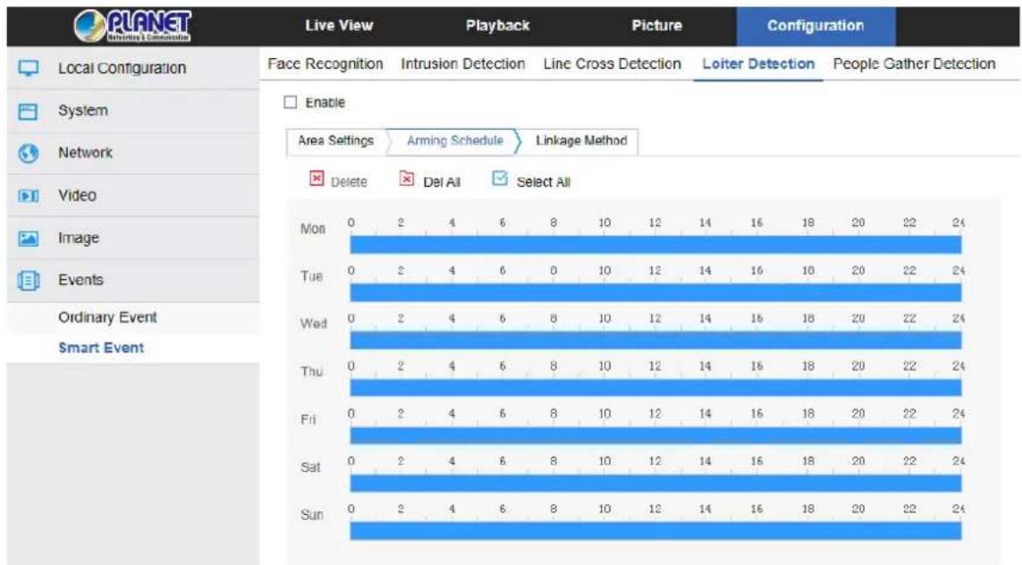
Figure 8-54

- When the arming time is set, there can be no overlap between any two time periods.
Step 6: Set the linkage method as needed.
【Linkage Method】 refers to the response made by the device when an alarm event occurs. The linkage includes "General Linkage", "Upload Via SMTP" and "Upload Via FTP".
⑤ People Gathering Detection
The people gathering detection function is used to detect that the density of the personnel in the set area exceeds the set threshold, and the alarm is linked according to the judgment result. The specific steps are as follows:
Step 1: In the main interface, click on the "Configuration → Events → Smart Event → People Gathering Detection" to enter the People Gathering Detection settings interface, as shown in Figure 8-55.
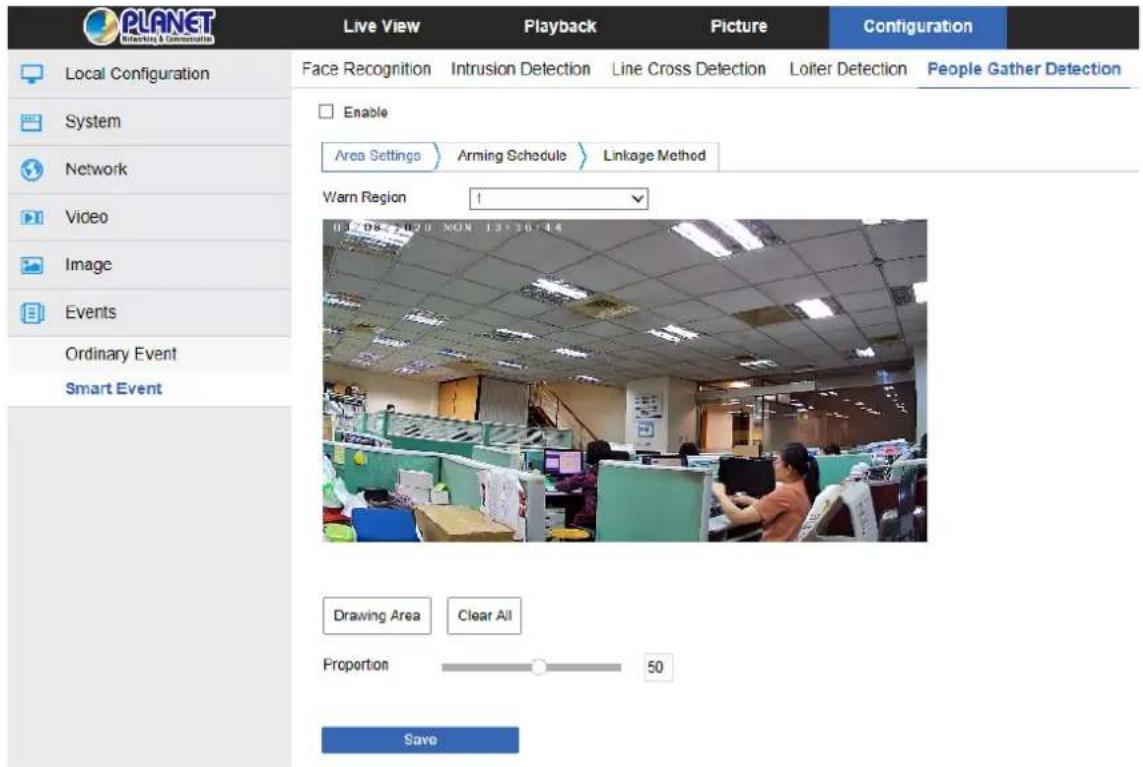
Figure 8-55
Step 2: Check "Enable" to enable intrusion detection.
Step 3: Select "Warn Region": The system supports setting up to 4 warn regions. After selecting a warn region, you need to make the following settings. After setting, please click "Save" below.
【Drawing Area】Click "Drawing Area", and move the mouse to the preview screen.
Click the left mouse button and draw the endpoint of the quadrilateral guard area, and then click the preview interface to complete the area drawing.
【Clear All】 Used to delete the selected alert area.
【Proportion】 Indicates the proportion of personnel in the entire alert area. When the proportion of personnel exceeds the set percentage, the system will generate an alarm. The percentage is 50% by default. The larger the value is, the more people can be accommodated in the alert area, and the less likely it is to trigger an alarm.
Step 4: When you need to set other Warn Region, repeat step 3 to complete the setup.
Step 5: Arming Schedule, as shown in Figure 8-56. You can view, edit, and delete the arming time of the People gather detection. The default is to arm the alarm 24 hours a day. You can adjust the arming time as follows:
- Method 1: Click the arming time period, manually fill in the start time and end time, set up and click Save. If you need to delete the time period, click the "Delete" button and then reset the time period.
Method 2: Click the time of deployment, the time period will display two circles at both ends. Move the mouse to the circle to show the left and right direction of the
adjustment arrow, and move the adjustment arrow to adjust the arming time.
- You can set up more than one time period for up to 8 time periods.
- After the day of deployment time is set, if the other time is also needed to set the
same arming time, click the right side of the timeline "☐" copy button. In the "copy to" interface, check the "Select All" or a day, then Click "OK".
- After setting, click "Save" to complete the setting of the arming time.
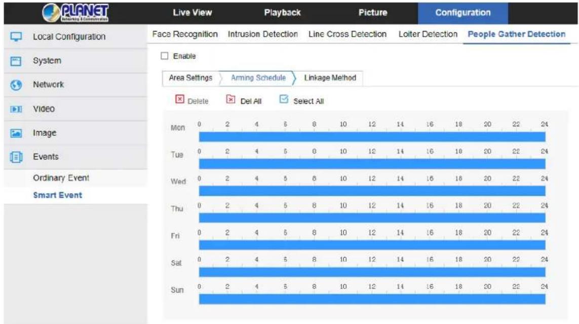
Figure 8-56

- When the arming time is set, there can be no overlap between any two time periods.
Step 6: Set the linkage method as needed.
【Linkage Method】 refers to the response made by the device when an alarm event occurs. The linkage includes “General Linkage”, “Upload Via SMTP” and “Upload Via FTP”.
Chapter 9 Frequently Asked Questions
| Features | |
| 1. Why can’t I access the IP camera by IE? | Answer: There may be 4 reasons. Details are as follows:a. The network is unreasonable sound?Solution: First you can connect network by PC, and check whether the network cable is good. And check whether the network between the camera and the PC is good.b. The IP address of the IP camera is occupied by another device or PC.Solution: You can connect the camera with your PC directly, and modify the IP address or use the IP search tool.c. The IP camera may be in another network segment?Solution: Check the IP address and net mask. |
| 2. Why can’t I access the IP camera after update? | Answer: Clear browser cache.Step: Open IE, click “Tools” and select “Internet Options” to see “Temporary Internet files” and click “Delete Files”. It will prompt a dialog you need to check “Delete all offline content” and click “OK”.Also you can click “Start” and select “Run” and then enter “cmd”, and “arp -d” in “Command Prompt” interface. Re-access the IP camera. |
| 3. Why can’t it show the whole interface? | Answer: Close some options of IE.Step: Open IE, click “View” and select “Toolbar” to close the “Favorites bar”, “Status bar” and “Command bar”. |
- Copyright
- FCC Interference Statement
- FCC Caution
- FCC Radiation Exposure Statement
- Safety
- CE Mark Warning
- WEEE Regulation
- Revision
- Legal Disclaimer
- Safety Instruction
- Warning
- Cautions
- Table of Contents
- CHAPTER 1 PRODUCT INTRODUCTION....8
- Product Features
- ■ System functions
- ● Video and capture functions
- - User management
- ● Video playback (ICA-A3280/A4280)
- ■ Event detection function
- - Ordinary event
- ● Smart event (ICA-A3280/A4280)
- ■ Internet function
- ■ Other function
- - Cloud storage function
- Chapter 2 Operating instructions
- Network Connection
- Wired network connection
- Detecting and Changing the IP Address
- Chapter 3 Access to the IP Camera by PVMS Software
- Chapter 4 Access to the IP Camera by Web Client
- Preparation before installing plugin
- Login and Exit
- Login
- Changing password
- Forget password
- Security question verification
- Security Key verification
- Exit System
- Installing the HsIPCCtl Controls
- Main interface description
- Chapter 5 Live preview
- Live preview
- Camera settings: PTZ, zoom and cruise
- Chapter 6 Playback
- Chapter 7 Picture
- Picture
- Chapter 8 Configuration
- Configuration
- Local Configuration
- System
- System Configuration
- ∅ Time Setting
- Scheduled Reboot
- Log Search
- Security
- ① Add a User
- ∅ First modified (admin user) password
- ③ Modify the (admin user) password again
- ④ Edit the User (new user)
- Delete Users
- SD Card
- ①SD Card
- 2Rec Setup
- Network
- Basic Setup
- TCP/IP
- Port
- Advanced Setup
- ① DDNS
- ② FTP
- Precondition
- The steps to configure FTP are as follows:
- ③ SMTP
- Sender
- Receiver
- ④ P2P
- P2P steps are as follows:
- App Client operation example
- Step 4: Live preview
- ⑤ Cloud
- ⑥ Other
- ⑦ PTZ
- IPEYE
- Video
- Video
- Audio
- Image
- OSD
- Events
- Ordinary Event
- Motion Detection
- ② Privacy Mask
- ③ Video Tampering
- ④ Alarm Input
- ⑤ Exception
- ROI
- Smart Event
- ① Face Recognition
- ② Intrusion Detection
- ③ Line Cross Detection
- ④ Loitering Detection
- ⑤ People Gathering Detection
- Chapter 9 Frequently Asked Questions
Brand : Planet
Model : ICA-4280
Category : Security Camera