
Q 15 - Loudspeaker RCF - Free user manual and instructions
Find the device manual for free Q 15 RCF in PDF.


| Product Type | Passive PA Speaker |
| Brand | RCF |
| Model | Q 15 |
| Speaker Type | 2-way, bass reflex |
| Woofer | 15" neodymium |
| Tweeter | 1" compression driver |
| Frequency Response | 50 Hz – 20 kHz |
| Power Handling (RMS) | 400 W |
| Power Handling (Peak) | 1600 W |
| Impedance | 8 ohms |
| Sensitivity | 98 dB (1W/1m) |
| Maximum SPL | 130 dB |
| Coverage Angle (H x V) | 90° x 60° |
| Enclosure Material | Plywood |
| Finish | Textured paint |
| Dimensions (H x W x D) | 700 x 440 x 400 mm |
| Weight | 20 kg |
| Input Connectors | 2x SpeakON NL4 |
| Mounting Options | Pole mount, flying points |
| Operating Temperature | 0°C to 40°C |
| Storage Temperature | -20°C to 60°C |
| Humidity Range | <90% non-condensing |
| Cleaning Instructions | Wipe with a dry or slightly damp cloth. Do not use solvents. |
| Safety Compliance | CE |
| Repair and Spare Parts | Contact authorized RCF service centers |
Frequently Asked Questions - Q 15 RCF
User questions about Q 15 RCF
0 question about this device. Answer the ones you know or ask your own.
Ask a new question about this device
Download the instructions for your Loudspeaker in PDF format for free! Find your manual Q 15 - RCF and take your electronic device back in hand. On this page are published all the documents necessary for the use of your device. Q 15 by RCF.
USER MANUAL Q 15 RCF
TWO-WAY POINT SOURCE MODULES
CONTENTS
ENGLISH
1 SAFETY PRECAUTIONS AND GENERAL INFORMATION 4
2 DESCRIPTION 6
3 CONNECTIONS 7
4 HORIZONTAL HANGING 9
4.1 HORIZONTAL HANGING OF 1 SPEAKER....9
4.2 HORIZONTAL HANGING OF 2 OR MORE SPEAKERS ....10
4.3 HORIZONTAL CONFIGURATIONS 12
5 VERTICAL HANGING....14
5.1 VERTICAL CONFIGURATIONS....16
6 VERTICAL HANGING WITH A 10° ANGLE....18
7 EXAMPLES OF MIXED CONFIGURATIONS 20
ITALIANO
1. SAFETY PRECAUTIONS AND GENERAL INFORMATION
The symbols used in this document give notice of important operating instructions and warnings which must be strictly followed.
 | CAUTION | Important operating instructions: explains hazards that could damage a product, including data loss |
 | WARNING | Important advice concerning the use of dangerous voltages and the potential risk of electric shock, personal injury or death. |
 | IMPORTANT NOTES | Helpful and relevant information about the topic |
 | SUPPORTS, TROLLEYS AND CARTS | Information about the use of supports, trolleys and carts. Reminds to move with extreme caution and never tilt. |
 | WASTE DISPOSAL | This symbol indicates that this product should not be disposed with your household waste, according to the WEEE directive (2012/19/EU) and your national law. |

IMPORTANT NOTES
This manual contains important information about the correct and safe use of the device. Before connecting and using this product, please read this instruction manual carefully and keep it on hand for future reference. The manual is to be considered an integral part of this product and must accompany it when it changes ownership as a reference for correct installation and use as well as for the safety precautions. RCF S.p.A. will not assume any responsibility for the incorrect installation and / or use of this product.
SAFETY PRECAUTIONS
- All the precautions, in particular the safety ones, must be read with special attention, as they provide important information.
2. Power supply from mains
a. The mains voltage is sufficiently high to involve a risk of electrocution; install and connect this product before plugging it in.
b. Before powering up, make sure that all the connections have been made correctly and the voltage of your mains corresponds to the voltage shown on the rating plate on the unit, if not, please contact your RCF dealer.
c. The metallic parts of the unit are earthed through the power cable. An apparatus with CLASS I construction shall be connected to a mains socket outlet with a protective earthing connection.
d. Protect the power cable from damage; make sure it is positioned in a way that it cannot be stepped on or crushed by objects.
e. To prevent the risk of electric shock, never open this product: there are no parts inside that the user needs to access.
f. Be careful: in the case of a product supplied by manufacturer only with POWERCON connectors and without a power cord, jointly to POWERCON connectors type NAC3FCA (power-in) and NAC3FCB (power-out), the following power cords compliant to national standard shall be used:
- EU: cord type H05VV-F 3G 3x2.5 mm2 - Standard IEC 60227-1
- JP: cord type VCTF 3x2 mm2; 15Amp/120V-- Standard JIS C3306
- US: cord type SJT/SJTO 3x14 AWG; 15Amp/125V\~ - Standard ANSI/UL 62
- Make sure that no objects or liquids can get into this product, as this may cause a short circuit. This apparatus shall not be exposed to dripping or splashing. No objects filled with liquid, such as vases, shall be placed on this apparatus. No naked sources (such as lighted candles) should be placed on this apparatus.
- Never attempt to carry out any operations, modifications or repairs that are not expressly described in this manual.
Contact your authorized service centre or qualified personnel should any of the following occur:
- The product does not function (or functions in an anomalous way).
- The power cable has been damaged.
- Objects or liquids have got in the unit.
- The product has been subject to a heavy impact.
- If this product is not used for a long period, disconnect the power cable.
- If this product begins emitting any strange odours or smoke, switch it off immediately and disconnect the power cable.
- Do not connect this product to any equipment or accessories not foreseen.
For suspended installation, only use the dedicated anchoring points and do not try to hang this product by using elements that are unsuitable or not specific for this purpose. Also check the suitability of the support surface to which the product is anchored (wall, ceiling, structure, etc.), and the components used for attachment (screw anchors, screws, brackets not supplied by RCF etc.), which must guarantee the security of the system / installation over time, also considering, for example, the mechanical vibrations normally generated by transducers.
To prevent the risk of falling equipment, do not stack multiple units of this product unless this possibility is specified in the user manual.
- RCF S.p.A. strongly recommends this product is only installed by professional qualified installers (or specialised firms) who can ensure correct installation and certify it according to the regulations in force.
The entire audio system must comply with the current standards and regulations regarding electrical systems.
- Supports, trolleys and carts.

The equipment should be only used on supports, trolleys and carts, where necessary, that are recommended by the manufacturer. The equipment / support / trolley / cart assembly must be moved with extreme caution. Sudden stops, excessive pushing force and uneven floors may cause the assembly to overturn. Never tilt the assembly.
-
There are numerous mechanical and electrical factors to be considered when installing a professional audio system (in addition to those which are strictly acoustic, such as sound pressure, angles of coverage, frequency response, etc.).
-
Hearing loss.
Exposure to high sound levels can cause permanent hearing loss. The acoustic pressure level that leads to hearing loss is different from person to person and depends on the duration of exposure. To prevent potentially dangerous exposure to high levels of acoustic pressure, anyone who is exposed to these levels should use adequate protection devices. When a transducer capable of producing high sound levels is being used, it is therefore necessary to wear ear plugs or protective earphones. See the manual technical specifications to know the maximum sound pressure level.
OPERATING PRECAUTIONS
- Place this product far from any heat sources and always ensure an adequate air circulation around it.
- Do not overload this product for a long time.
- Never force the control elements (keys, knobs, etc.).
- Do not use solvents, alcohol, benzene or other volatile substances for cleaning the external parts of this product.

IMPORTANT NOTES
To prevent the occurrence of noise on line signal cables, use screened cables only and avoid putting them close to:
- Equipment that produces high-intensity electromagnetic fields
- Power cables
- Loudspeaker lines


WARNING! CAUTION! To prevent the risk of fire or electric
shock, never expose this product to rain or humidity.

WARNING! To prevent electric shock hazard, do not connect to power supply while grille is removed

WARNING! to reduce the risk of electric shock, do not disassemble product unless you are qualified. Refer servicing to qualified service level.
1. SAFETY PRECAUTIONS AND GENERAL INFORMATION
CORRECT DISPOSAL OF THIS PRODUCT

This product should be handed over to an authorized collection site for recycling waste electrical and electronic equipment (EEE). Improper handling of this type of waste could have a possible negative impact on the environment and human health due to potentially hazardous
substances
that are generally associated with EEE. At the same time, your cooperation in the correct disposal of thisproduct will contribute to the effective usage of natural resources. For more information about where you can drop off your waste equipment for recycling, please contact your local city office, waste authority or your household waste disposal service.
CARE AND MAINTENANCE
To ensure a long-life service, this product should be used following these advices:
- If the product is intended to be set up outdoors, be sure it is under cover and protected to rain and moisture.
- If the product needs to be used in a cold environment, slowly warm up the voice coils by sending a low-level signal for about 15 minutes before sending high-power signals.
- Always use a dry cloth to clean the exterior surfaces of the speaker and always do it when the power is turned off.

CAUTION: to avoid damaging the exterior finishes do not use solvents or abrasives.


WARNING! CAUTION! For powered speakers, do cleaning
only when the power is turned off.
2. DESCRIPTION
Q 15, Q 15-L, Q 15-P - TWO-WAY POINT SOURCE MODULES
Q 15 speakers are two-way, bi-amp point source modules for mid distance and long throw applications, merging a compact size with a very high output and accurate voice and sound reproduction. The systems are equipped with the latest generation of RCF precision transducers: a 15" neodymium woofer (4.0" v.c.) and a 1.4" exit compression driver (4.0" v.c.) providing 1500 W power rating.
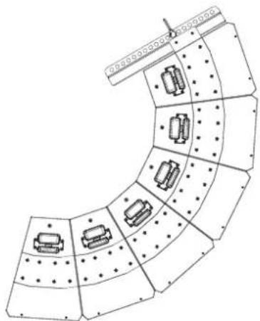
Directivity, horizontal 22.5° and vertical 60° (Q 15), 90° (Q 15-L), 40° (Q 15-P) makes Q 15 speakers ideal to be used in point source configuration for mid distance applications or clustered with narrower angles for long throw applications. The enclosure shape is trapezoidal and offers a 22.5° coupling angle each side. Thanks to two different fly bars, it can be clustered both horizontally (up to 4 modules with the same fly bar) and vertically (up to 6 modules with one flybar and up to 8 modules with two fly-bars). Connections to the amplifier are made through Speakon multi-pole connectors. The grille is in custom perforated steel epoxy coated, with woven fabric backing. The cabinet is made of multi-ply Baltic birch plywood and finished in a very resistant polyurea black paint.
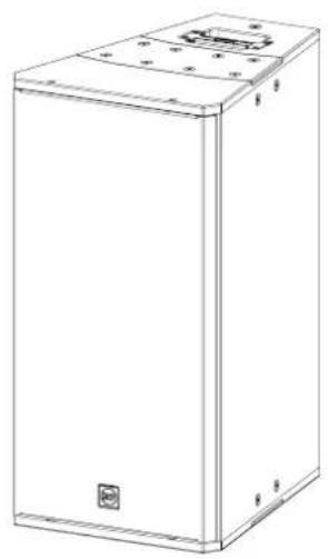
natural_image
Line drawing of a rectangular industrial enclosure or enclosure with mounting holes and a small inset component (no text or symbols)Q 15
Horizontal directivity: 22.5°
Vertical directivity: 60°
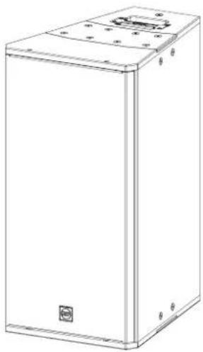
natural_image
Line drawing of a rectangular industrial enclosure or enclosure with mounting holes and a small internal component (no text or symbols)Q 15-L
Horizontal directivity: 22.5°
Vertical directivity: 90°
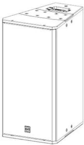
natural_image
Line drawing of a rectangular industrial enclosure with mounting holes and a small inset component (no text or symbols)Q 15-P
Horizontal directivity: 22.5°
Vertical directivity: 40°
3. CONNECTIONS
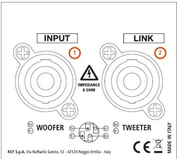
THE REAR PANEL
The rear panel displays 2 sockets, both for 'Neutrik Speakon NL4' (4-pole) plugs:
① The INPUT socket receives the signal from the amplifier
② The LINK socket can be used to link another speaker
'BI-AMP' MODE
The speaker must be powered by two amplifiers (one for the low frequency, one for the high frequency) and an external crossover is required. Check in the specification table the impedance of both ways, their power and the suggested crossover frequency.
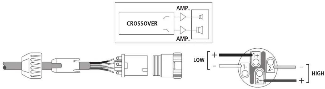
CONNECTIONS
- Low frequency amplifier + output to the pin 1+ of the SPEAKON connector
- Low frequency amplifier - output to the pin 1- of the SPEAKON connector
- High frequency amplifier + output to the pin 2+ of the SPEAKON connector
- High frequency amplifier - output to the pin 2- of the SPEAKON connector

WARNING! CAUTION! Loudspeaker connections should be only made by qualified and experienced personnel having the technical know-how or enough specific instructions (to ensure that connections are made correctly) in order to prevent any electrical danger.
To prevent any risk of electric shock, do not connect loudspeakers when the amplifier is switched on.
Before turning the system on, check all connections and make sure there are no accidental short circuits.
The entire sound system shall be designed and installed in compliance with the current local laws and regulations regarding electrical systems.
3. CONNECTIONS
NOTES ABOUT LOW IMPEDANCE CONNECTIONS
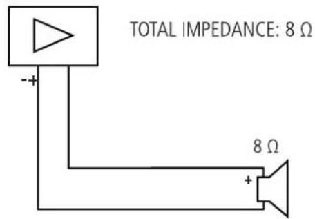
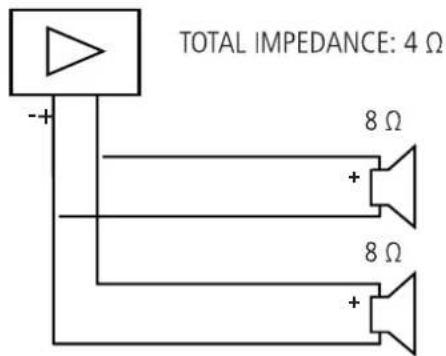


WARNING! CAUTION!
- The total loudspeaker impedance must not be lower than the amplifier output impedance. Note: a loudspeaker total impedance equal to the amplifier output one permits to get the maximum deliverable power (but an higher loudspeaker impedance entails less power).
- The total loudspeaker power shall be adequate for the maximum deliverable power of the amplifier.
- The loudspeaker line shall be short (for long distances, it may be necessary to use cables with large cross-section wires).
- Always use cables having wires with an adequate cross-section, considering the cable length and the total loudspeaker power.
- Loudspeaker lines must be kept separated from the mains cables, microphone cables or others, in order to avoid inductive phenomena may cause hum or noises.
- Use loudspeaker cables with twisted wires to reduce hum caused by inductive effects due to coupling with electromagnetic fields.
- Do NOT connect the low impedance input directly to 70 / 100 V constant voltage lines.
4. HORIZONTAL HANGING
Up to 4 x Q 15 can be hanged horizontally by using the horizontal flybar FLY BAR FL-B H Q 15.
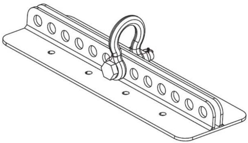
natural_image
Technical line drawing of a mechanical support bracket with circular holes and a looped hook (no text or symbols)4.1 HORIZONTAL HANGING OF 1 SPEAKER
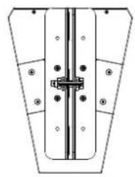
- Unscrew the 4 central screws from the Top Plate
- Secure the Flybar with the 4 x M10 screws provided.
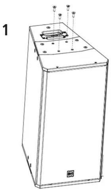
natural_image
Line drawing of a rectangular electronic device with mounting holes and a central internal component (no text or symbols)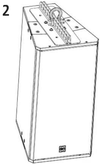
natural_image
Line drawing of a rectangular electronic device with mounting flanges and a coiled cable (no text or symbols)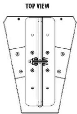
natural_image
Top view diagram of a mechanical or structural component with mounting holes and a central vertical shaft (no text or symbols)4. HORIZONTAL HANGING
4.2 HORIZONTAL HANGING OF 2 OR MORE SPEAKERS
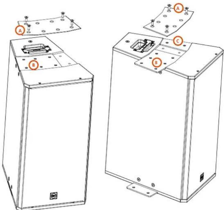
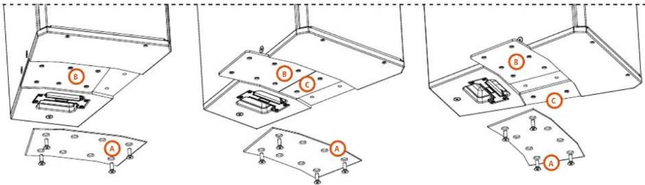
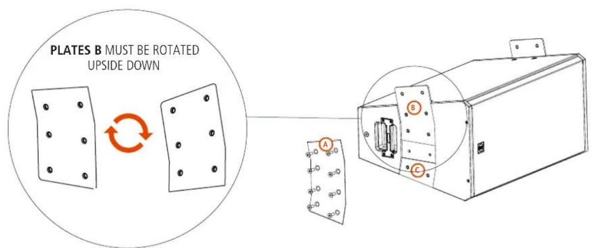
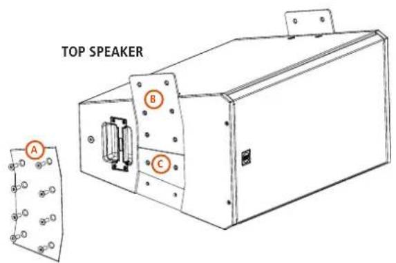
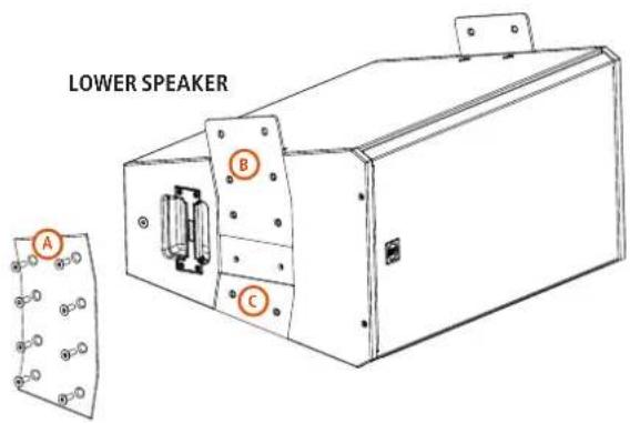
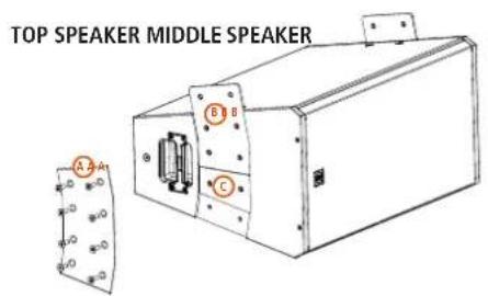
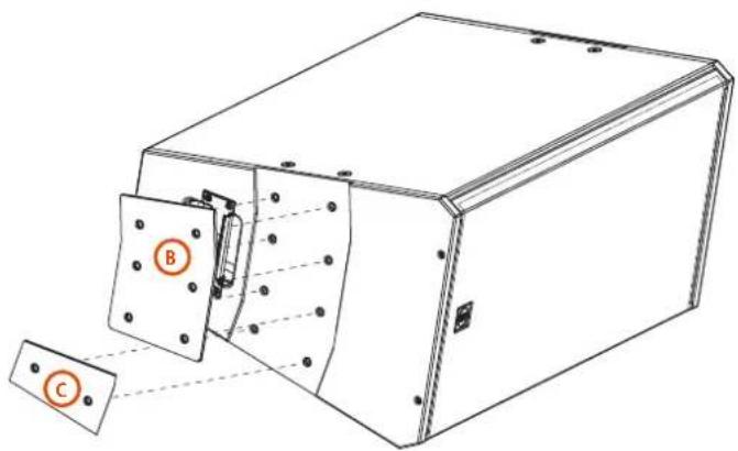
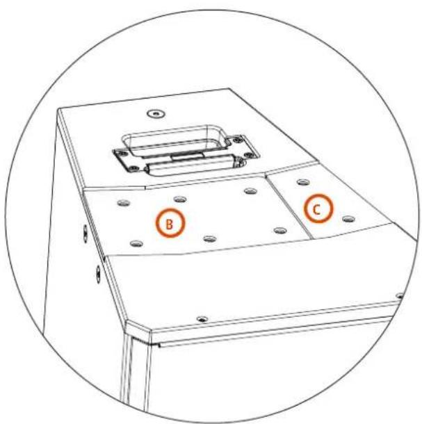
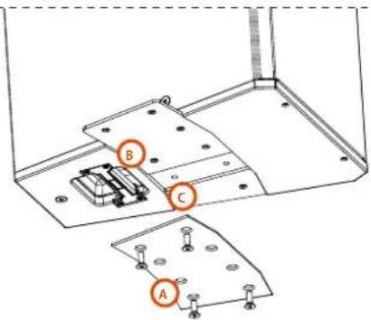
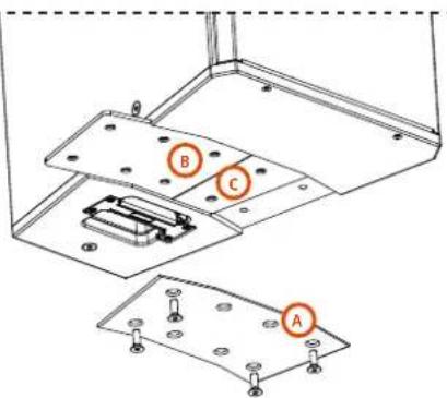
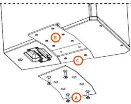
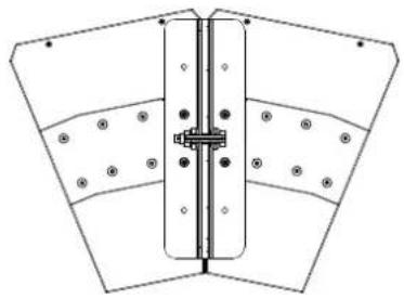
Unscrew the 8 screws from the Top Plate A and remove it. There are 2 plates below the Top Plate:
B a Link Plate (with 6 holes)
c an External Plate (with 2 holes)
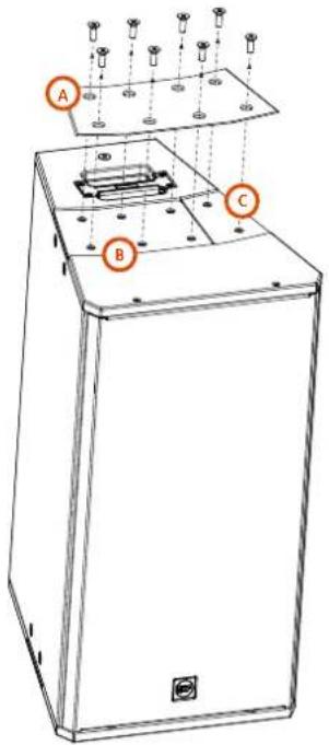
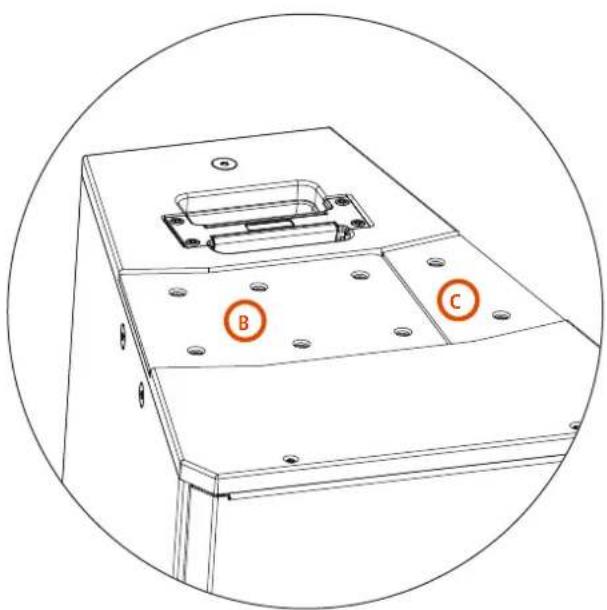
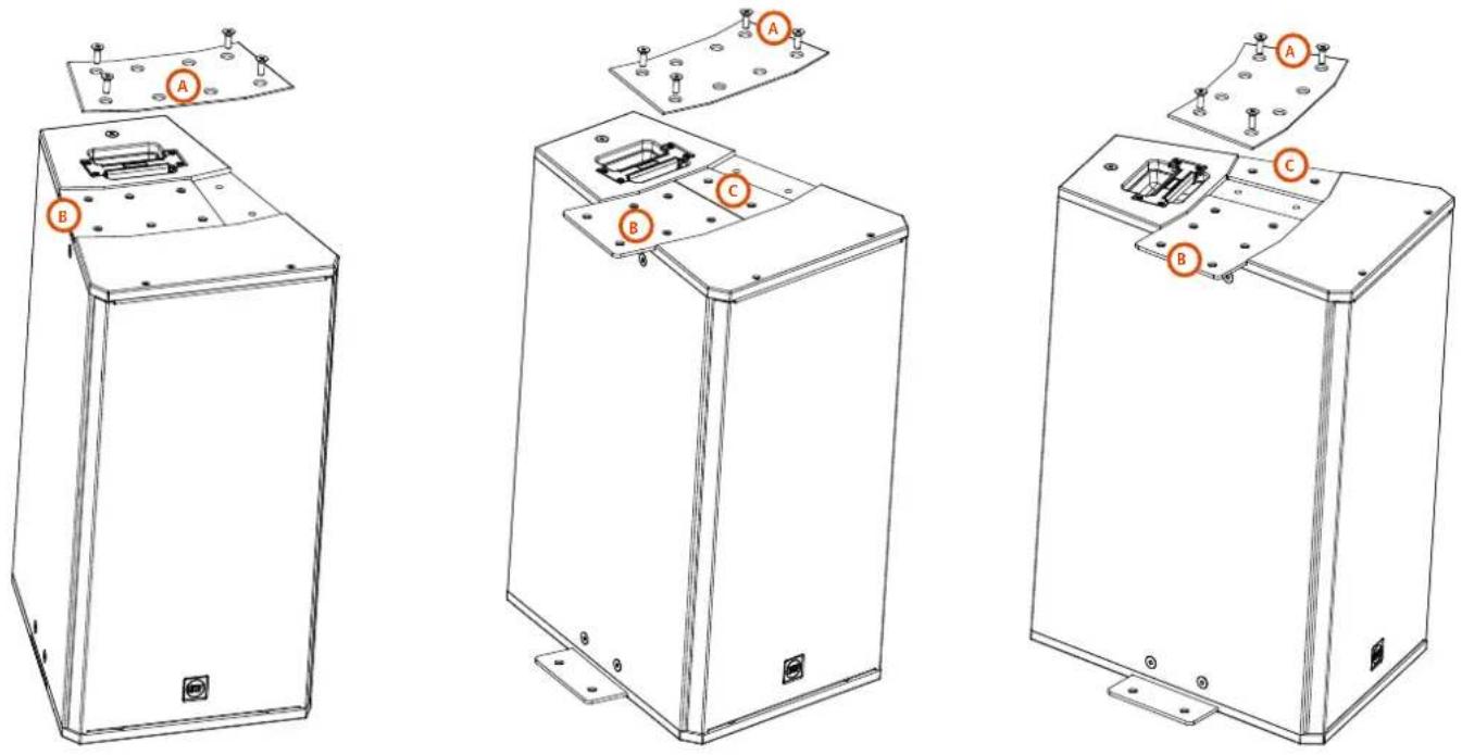
These two plates are designed to be moved from their position in order to link another speaker on its side depending on the configuration wanted.
Example: for a 2 speakers horizontal configuration, this is how the two plates must be positioned:
4. HORIZONTAL HANGING
Example: for a 3 speakers configuration, this is how the two plates must be positioned:
NOTE: The exact same operations done on the upper side of the speaker must be done on the bottom side too.
BOTTOM VIEW of a 2 SPEAKERS CONFIGURATION
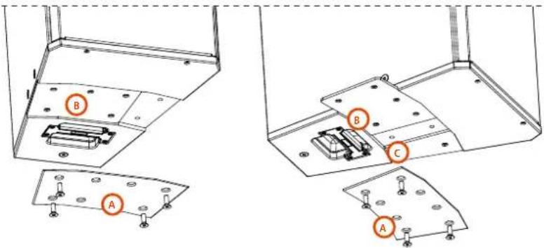
BOTTOM VIEW of a 3 SPEAKERS CONFIGURATION
NOTE: Once chosen the right configuration the Top Plate must be always screwed back on its position, leaving the four middle holes free.
4.3 HORIZONTAL CONFIGURATIONS
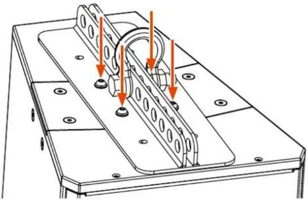
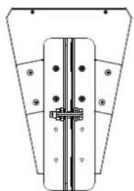
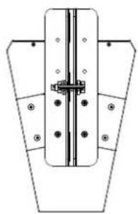
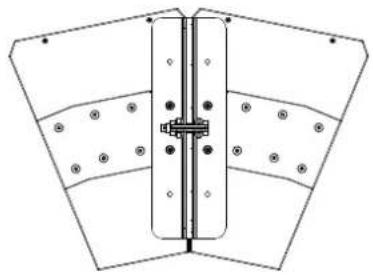
Once screwed back the top plate, secure the horizontal flybar over the top plate by screwing (on the middle holes) the four M10 screws provided.
natural_image
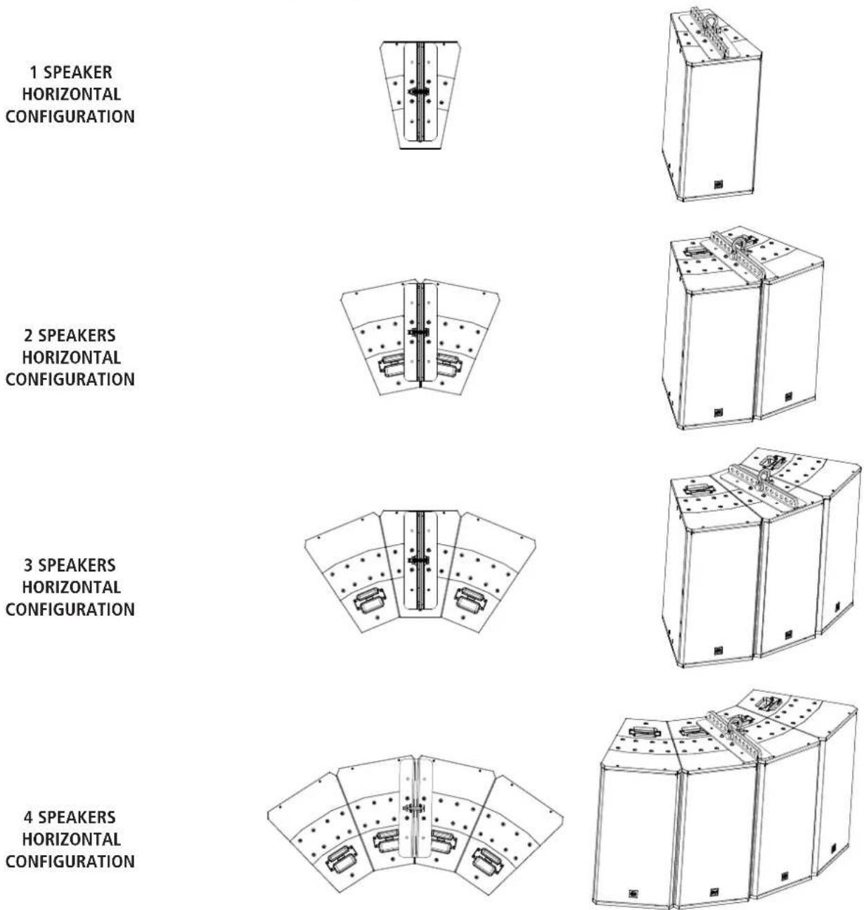
Technical line drawing of a mechanical assembly with orange arrows indicating force or movement (no text or symbols present)These are all the 4 possible configurations by using one single Flybar:

NOTE: The Flybar can be positioned backward or forward to even increase the desired inclination.
natural_image
Pure technical diagram of a mechanical assembly with no visible text, numbers, or symbolsFLYBAR ON CENTRAL POSITION
natural_image
Pure technical diagram of a mechanical assembly without any text, numbers, or symbolsFLYBAR ON BACKWARD POSITION
natural_image
Pure technical diagram of a mechanical assembly with no text, numbers, or symbolsFLYBAR ON FORWARD POSITION
natural_image
Pure technical diagram of a mechanical assembly with no text, numbers, or symbols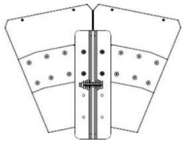
natural_image
Pure technical diagram of a mechanical assembly with no text, numbers, or symbols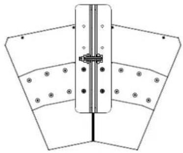
natural_image
Pure mechanical assembly diagram showing a central component with flanged sides and bolt holes, no text or symbols present.
CAUTION: do not hang more than 4 speakers to one single horizontal flybar. To hang 5 ore more speakers, more mental flybars are required.
5. VERTICAL HANGING
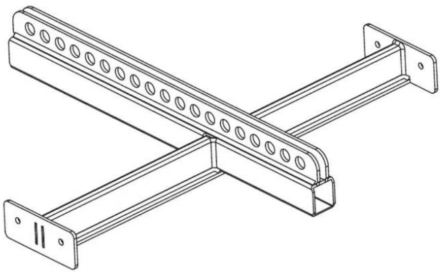
4 x Q 15 can be hanged vertically by using the vertical flybar FLY BAR FL-B V Q 15.
natural_image
Technical line drawing of a metal beam with circular holes and mounting flanges (no text or symbols)To vertically hang a series of Q 15 speakers, unscrew the 8 screws from the Top Plate A and remove it.
As described on chapter 4.1 (Horizontal hanging of 2 or more speakers), two plates are located under the top one:

a Link Plate (with 6 holes)

an External Plate (with 2 holes)
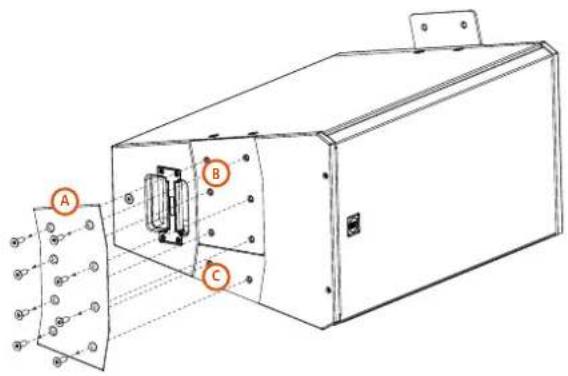
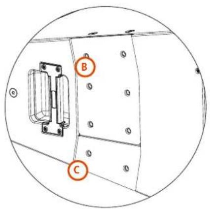
These two plates are designed to be moved from their position in order to link another speaker on its side depending on the configuration wanted.
Example: for a 1 speaker vertical configuration, this is how the two plates must be positioned:
5. VERTICAL HANGING
Example: for a 2 speakers vertical configuration, this is how the plates must be positioned:
Example: for a 3 speakers vertical configuration, this is how the plates must be positioned:
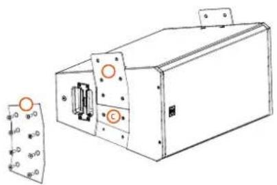
natural_image
Technical line drawing of a mechanical device with mounting holes and a separate inset showing a circular component labeled 'C' (no text or symbols present)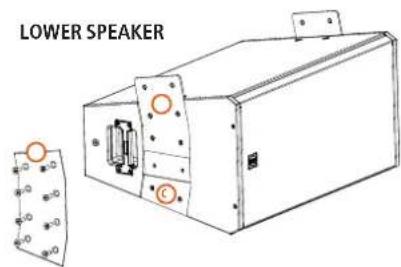
i NOTE: The exact same operations must be done on both sides of the speaker
NOTE: Once chosen the right configuration the Top Plate must be always screwed back on its position.
5. VERTICAL HANGING
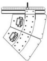
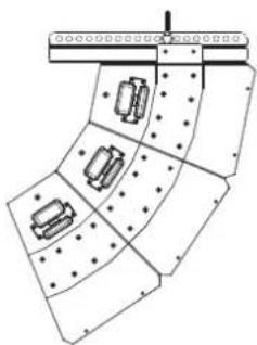
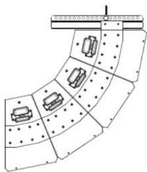
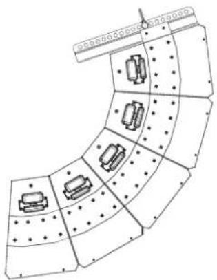
5.1 VERTICAL CONFIGURATIONS
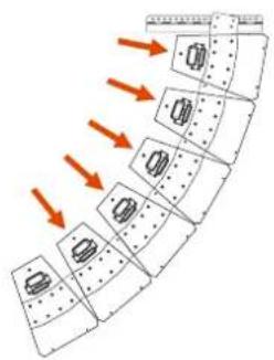
Once screwed back the top plate, secure the vertical flybar on the exposed portion of the Link Plate with the four M10 bolts provided. Secure every bolt with the eight nuts provided (two nuts for each bolt).
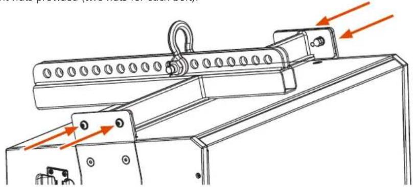
natural_image
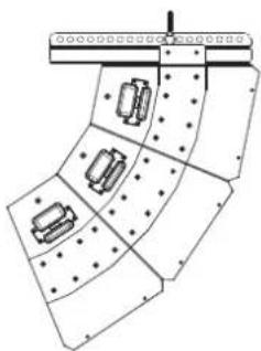
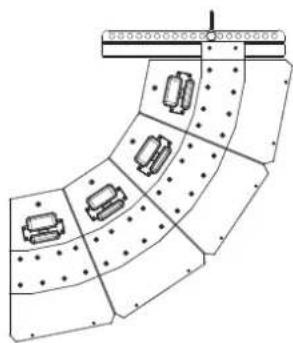
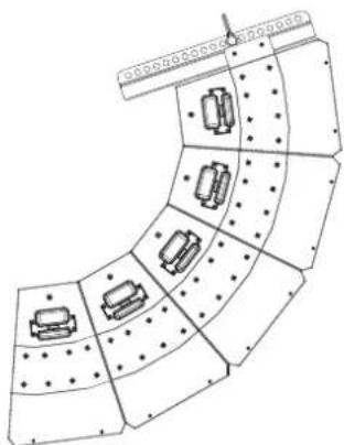
Technical line drawing of a mechanical assembly with orange arrows indicating motion or force direction (no text or symbols present)These are the possible horizontal configurations by using one single Flybar:
1 SPEAKER
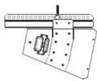
2 SPEAKERS
natural_image
Pure technical diagram of a mechanical assembly with no text, numbers, or symbols3 SPEAKERS
natural_image
Pure mechanical assembly diagram showing a folded component with multiple slots and mounting holes (no text or symbols)4 SPEAKERS
natural_image
Pure technical diagram of a curved structural component with internal components and bolt holes, no text or symbols present.5 SPEAKERS
natural_image
Pure architectural or engineering diagram showing curved structural elements with no text, numbers, or symbols6 SPEAKERS
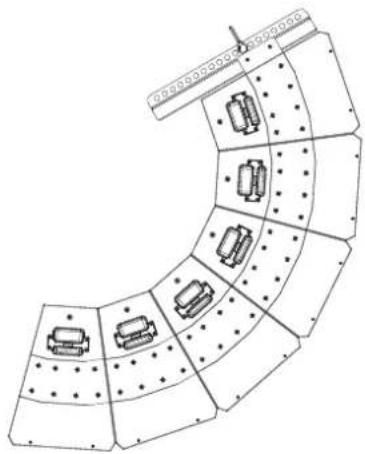
natural_image
Diagram of a curved structural layout with embedded rectangular components and dot patterns (no text or symbols)
CAUTION: do not hang more than 6 speakers to one single vertical flybar.
5. VERTICAL HANGING
An additional 8 speakers vertical configuration can be done by using two vertical flybars.
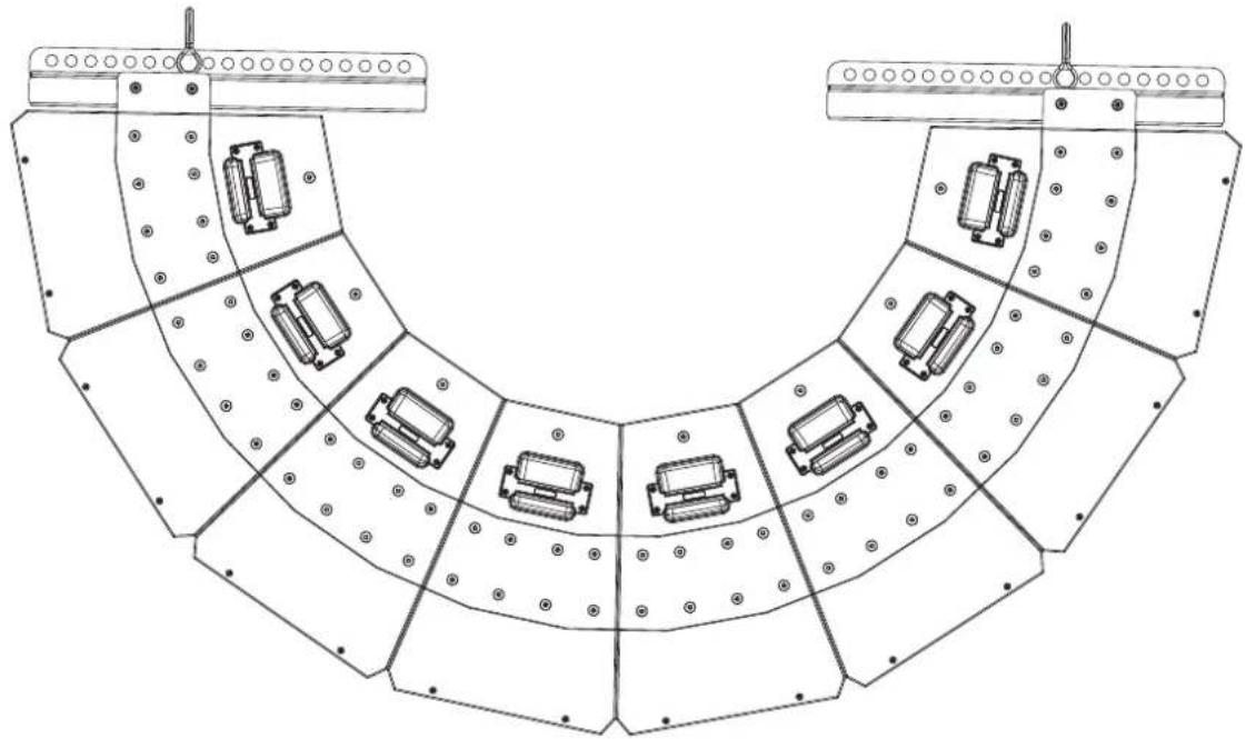
natural_image
Technical line drawing of a mechanical assembly with multiple curved components and mounting brackets (no text or symbols)6. VERTICAL HANGING WITH A 10° ANGLE
Using the C-BR 10° it is possible to reduce the opening angle from 22.5° to 10°.
PACKAGE CONTENT: - 2 X C-BR 10° BRACKETS
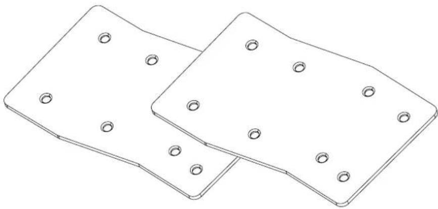
natural_image
Technical line drawing of two square metal plates with circular holes (no text or symbols)- Unscrew the 8 screws from the Top Plate A and remove it.
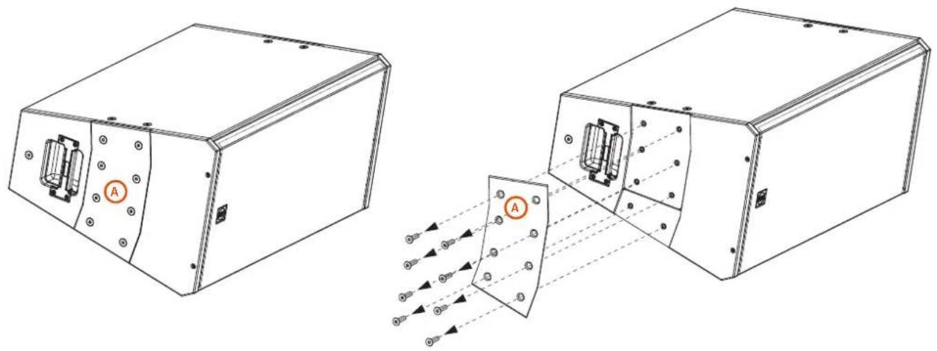
natural_image
Technical line drawing of two electronic enclosure units with labeled components and internal wiring diagram (no text or symbols)- Remove the two plates located under the top one:
B a Link Plate (with 6 holes)
© an External Plate (with 2 holes)
natural_image
Technical line drawing of a mechanical device with labeled components (B, C), showing internal components and mounting holes (no text or symbols beyond labels)6. VERTICAL HANGING WITH A 10° ANGLE
-
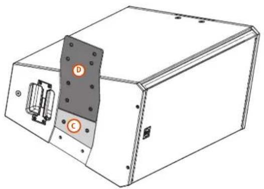
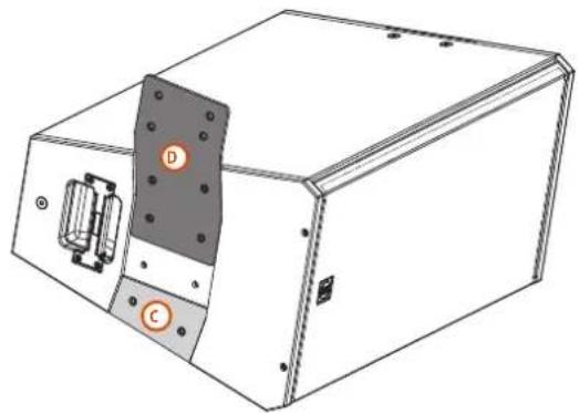
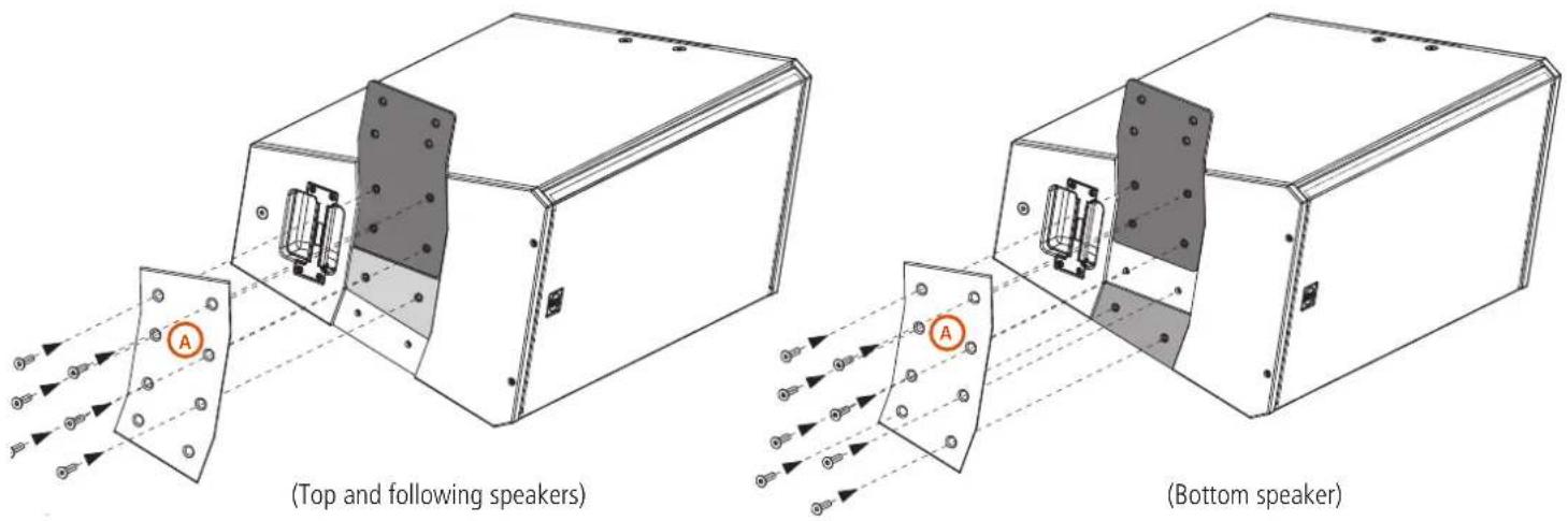
Place the C-BR 10° D as shown in the pictures below.
-
On the top and following speakers of the cluster, the External Plate C must be placed next to the C-BR 10°, as shown in FIGURE 1.
- On the bottom speaker of the cluster the External Plate c must be placed as shown in FIGURE 2.
natural_image
Technical line drawing of a mechanical device with labeled components (D, C) and internal components (no text or symbols beyond labels)FIGURE 1 (Top and following speakers)
natural_image
Technical line drawing of a mechanical device with labeled components (D, C), no readable text or symbols present.FIGURE 2 (Bottom speaker)
flowchart
graph TD
    A["●"] --> B["○"]
    C["○"] --> D["○"]
    E["○"] --> F["○"]
    G["○"] --> H["○"]
    I["○"] --> J["○"]
    K["○"] --> L["○"]
    M["○"] --> N["○"]
    O["○"] --> P["○"]
    Q["○"] --> R["○"]
    S["○"] --> T["○"]
    U["○"] --> V["○"]
    W["○"] --> X["○"]
    Y["○"] --> Z["○"]
    AA["○"] --> AB["○"]
    AC["○"] --> AD["○"]
    AE["○"] --> AF["○"]
    AG["○"] --> AH["○"]
    AI["○"] --> AJ["○"]
    AK["○"] --> AL["○"]
    AM["○"] --> AN["○"]
    AO["○"] --> AP["○"]
    AQ["○"] --> AR["○"]
    AS["○"] --> AT["○"]
    AU["○"] --> AV["○"]
    AW["○"] --> AX["○"]
natural_image
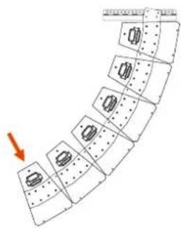
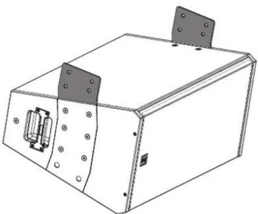
Diagram of a multi-layered structure with circular elements and a red arrow indicating direction (no text or symbols)- For the top and following speakers, place back the Top Plate on its position and screw it back with only six screws, leaving the two bottom holes empty. For the Bottom speakers screw back the Top Plate with all the 8 screws.

NOTE: The Top Plate A must be always screwed back on its position.

NOTE: The exact same operations must be done on both sides of the speaker
natural_image
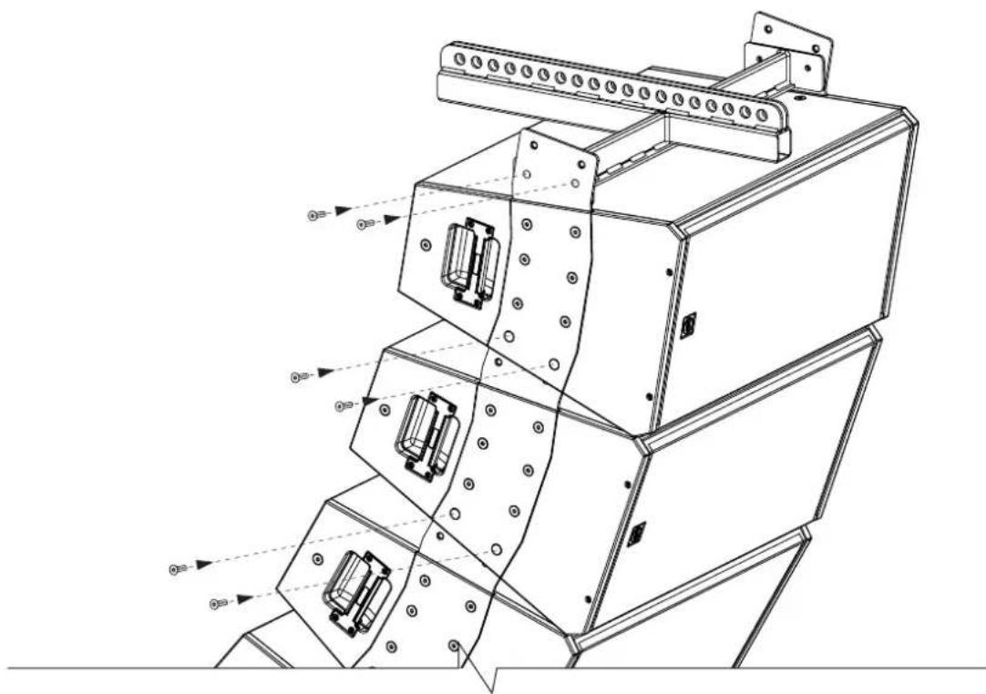
Technical line drawing of a rectangular electronic device with mounting flanges and a central internal component (no text or symbols)- Now place the Vertical Fly Bar on top of a Q15 speaker and screw it with the 4 screws provided.
The protruding part of the 10^ bracket of the lower speaker must be inserted on the respective seat on the upper speaker. Then depending on which angle is chosen, screw in the last two screws.
natural_image
Technical line drawing of a multi-tiered industrial machine with mounting flanges and internal components (no text or symbols)
NOTE: The exact same operations must be done on both sides of the speaker
7. EXAMPLES OF CONFIGURATIONS
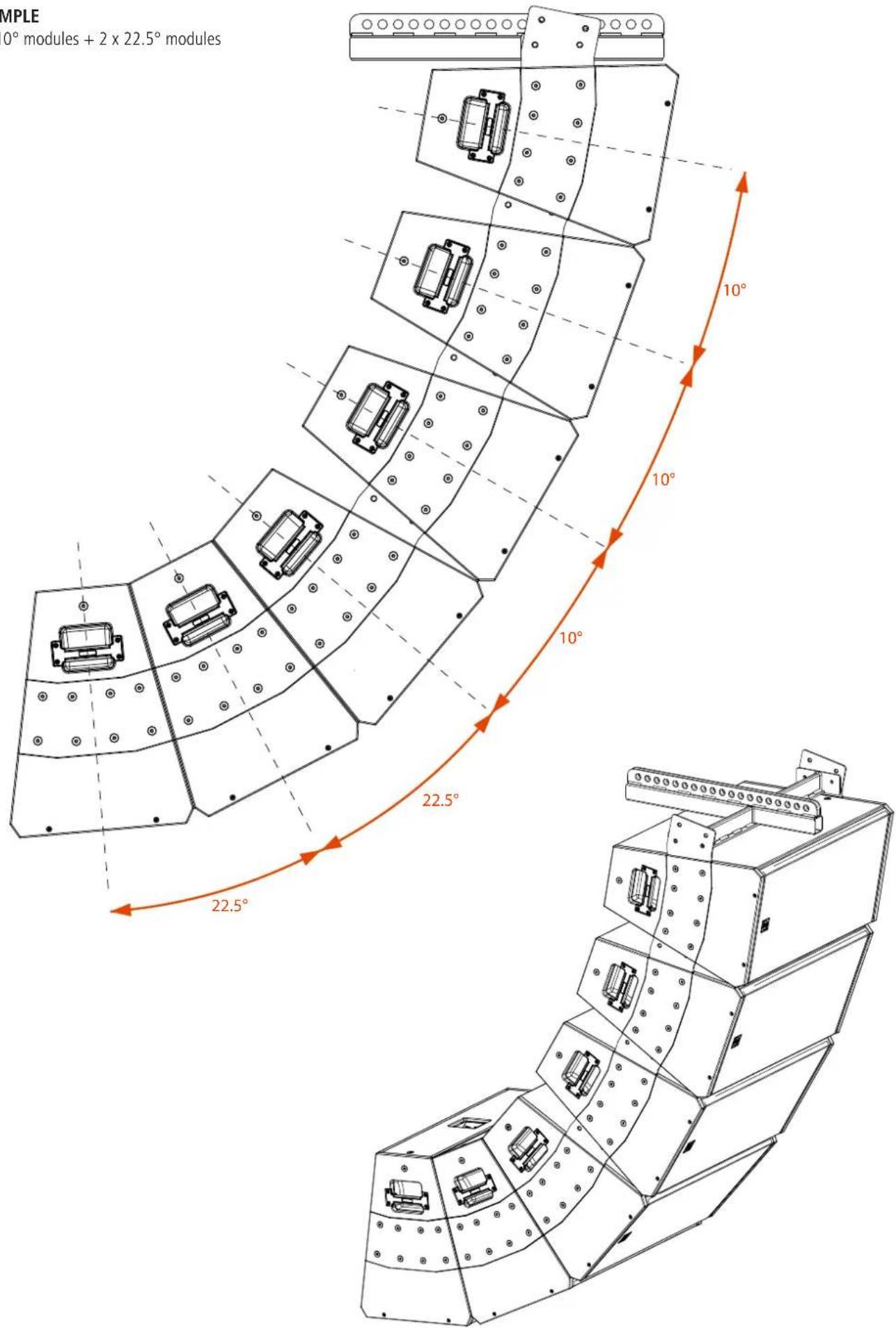
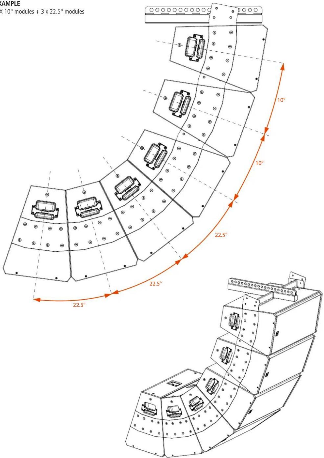
Now with the vertical flybar FLY BAR FL-B V Q 15 you can hang vertically multiple Q 15 speakers (maximum 6).
EXAMPLE
6 X 10° modules
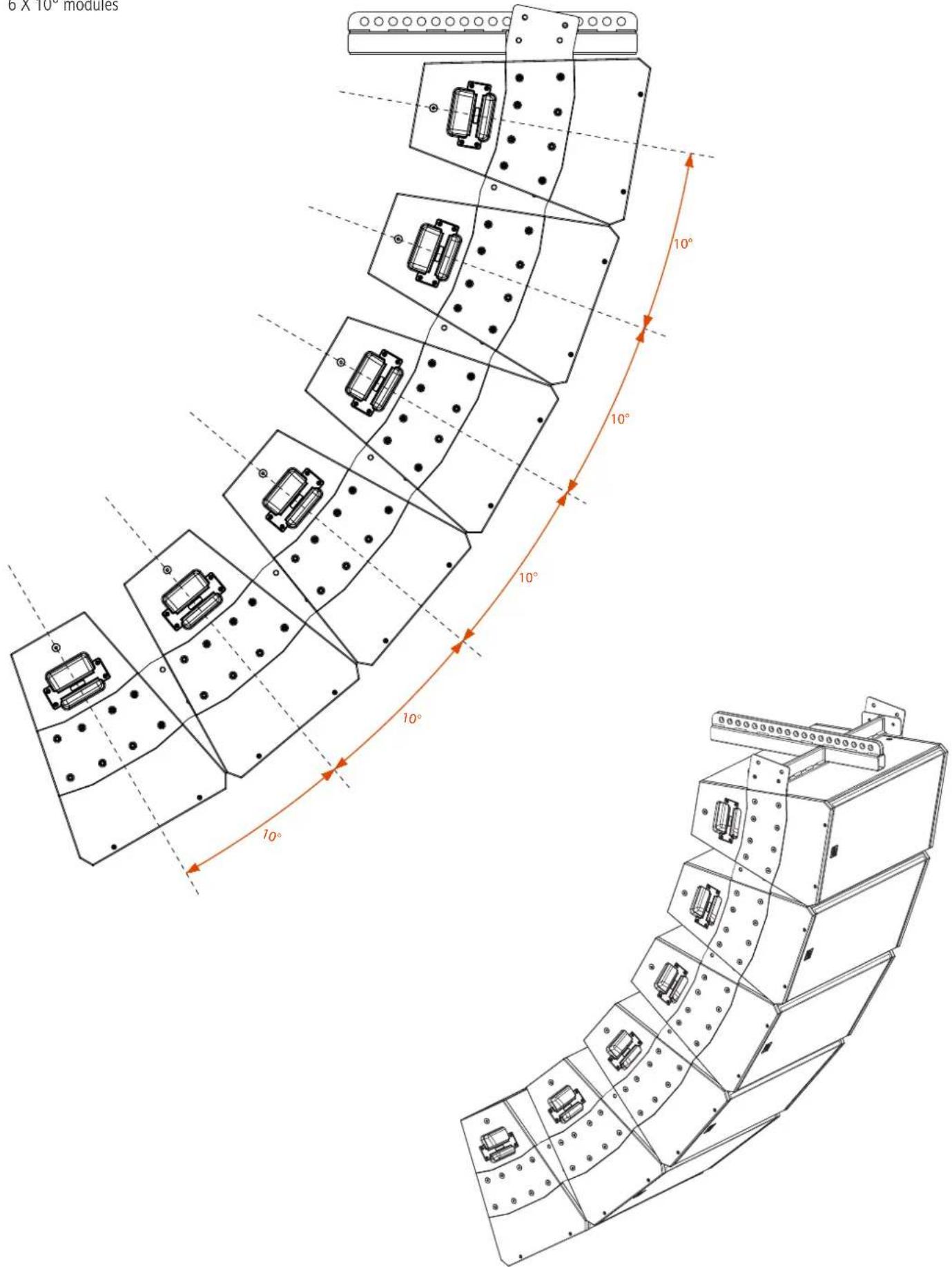
EXAMPLE
4 × 10^ modules + 2 × 22.5^ modules
7. EXAMPLES OF MIXED CONFIGURATIONS
EXAMPLE
3 × 10° modules + 3 × 22.5° modules
1. AVVERTENZE PER LA SICUREZZA E INFORMAZIONI GENERALI
Q 15, Q 15-L, Q 15-P - MODULI POINT SOURCE A DUE VIE
natural_image
Line drawing of a rectangular industrial enclosure or enclosure with mounting holes and a small inset component (no text or symbols)natural_image
Line drawing of a rectangular industrial enclosure or enclosure with mounting flanges and a small internal component (no text or symbols)natural_image
Line drawing of a rectangular electronic device with mounting holes and a central lid (no text or symbols)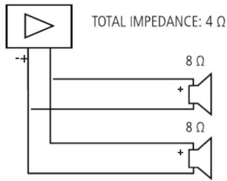


NIZIONE! CAUTELA!
natural_image
Technical line drawing of a mechanical support bracket with circular holes and a looped hook (no text or symbols)4.1 SOSPENSIONE ORIZZONTALE DI 1 DIFFUSORE
natural_image
Line drawing of a rectangular electronic device with mounting holes and a central internal component (no text or symbols)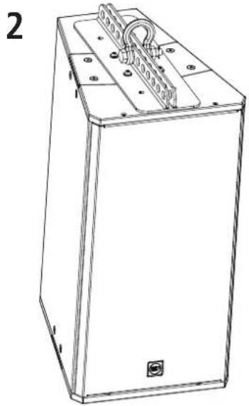
natural_image
Line drawing of a rectangular electronic device with mounting flanges and a central connector (no text or symbols)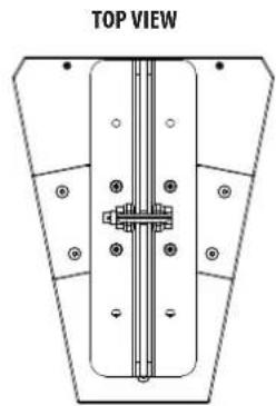
natural_image
Top view diagram of a mechanical or structural component with mounting holes and internal components (no text or symbols)4. SOSPENSIONE ORIZZONTALE
4.2 SOSPENSIONE ORIZZONTALE DI 2 O PIÙ DIFFUSORI
4. SOSPENSIONE ORIZZONTALE

natural_image
Technical line drawing of a mechanical assembly with orange arrows indicating force or movement (no text or symbols present)natural_image
Line drawing of a rectangular electronic device with mounting holes and a coiled cable (no text or symbols)natural_image
Pure technical diagram of a mechanical assembly with no text, numbers, or symbols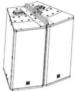
natural_image
Line drawing of a two-bar electrical enclosure with mounting holes and internal components (no text or symbols)natural_image
Diagram of a mechanical or electrical component with two labeled parts and a central vertical structure (no text or symbols)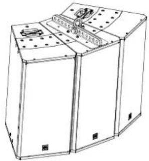
natural_image
Line drawing of three rectangular industrial equipment units with mounting holes and internal components (no text or symbols)natural_image
Diagram of a fan-shaped structure with internal components and dot patterns (no text or symbols)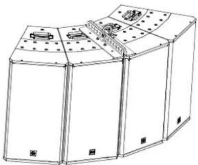
natural_image
Line drawing of three rectangular industrial equipment units with mounting holes and internal components (no text or symbols)
natural_image
Pure technical diagram of a mechanical assembly with no visible text, numbers, or symbolsnatural_image
Pure technical diagram of a mechanical assembly with no text, numbers, or symbolsnatural_image
Pure technical diagram of a mechanical assembly with no text, numbers, or symbolsFLYBAR IN
POSIZIONE
POSTERIORE
natural_image
Pure mechanical assembly diagram showing a central vertical component with mounting holes and flanges (no text or symbols)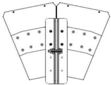
natural_image
Pure technical diagram of a mechanical assembly with no text, numbers, or symbols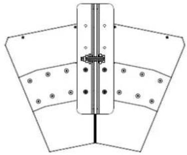
natural_image
Pure technical diagram of a mechanical assembly with no text, numbers, or symbols
natural_image
Technical line drawing of a mechanical support structure with two metal beams and circular holes (no text or symbols)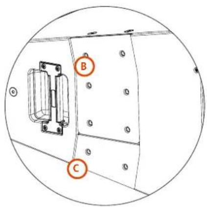
natural_image
Technical line drawing of a mechanical assembly with orange arrows indicating motion or force direction (no text or symbols present)natural_image
Pure technical diagram of a mechanical assembly with no text, numbers, or symbols3 DIFFUSORI
natural_image
Pure mechanical assembly diagram showing a folded panel with multiple slots and mounting holes (no text or symbols)4 DIFFUSORI
natural_image
Pure technical diagram of a curved mechanical or structural component with internal components and mounting holes (no text or symbols)5 DIFFUSORI
natural_image
Diagram of a curved architectural or mechanical structure with multiple rectangular components and dot patterns, no visible text or symbols.6 DIFFUSORI
natural_image
Diagram of a curved mechanical or electrical component with multiple rectangular components and dot patterns, no text or symbols present.
natural_image
Technical line drawing of a mechanical assembly with multiple curved components and mounting brackets (no text or symbols)6. SOSPENSIONE VERTICALE CON ANGOLO DI 10°
natural_image
Technical line drawing of two square metal plates with circular holes (no text or symbols)natural_image
Technical line drawing of two electronic enclosure units with labeled components and internal wiring (no text or symbols present)natural_image
Technical line drawing of a mechanical device with labeled components (B, C), showing internal components and mounting holes (no text or symbols beyond labels)6. SOSPENSIONE VERTICALE CON ANGOLO DI 10°
natural_image
Technical line drawing of a mechanical device with labeled components (D, C), no readable text or symbols present.natural_image
Technical line drawing of a mechanical enclosure with labeled components (D, C) and mounting holes (no text or symbols beyond labels)natural_image
Technical line drawing of a rectangular electronic device with mounting flanges and internal components (no text or symbols)natural_image
Technical line drawing of a mechanical device with multiple ports and mounting brackets (no text or symbols)
RCF products are continually improved. All specifications are therefore subject to change without notice. We recommend you to regularly check the RCF website for the latest version of this document
| Acoustical specifications | Frequency Response (-10dB): | 45 Hz ÷ 20000 Hz |
| Max SPL @ 1m: | 138 dB | |
| Horizontal coverage angle: | 22,5° | |
| Vertical coverage angle: | 60° (Q 15), 90° (Q 15-L), 40° (Q 15-P) | |
| Directivity index Q: | 20 | |
| Power section | Nominal Impedance (ohm): | 8 ohm |
| Power Handling: | 1500 W RMS | |
| Peak Power Handling: | 6000 W PEAK | |
| Recommended Amplifier: | 3000 W | |
| Protections: | Capacitor on Compression Driver | |
| Crossover Frequencies: | 600 Hz | |
| Transducers | Compression Driver: | 1 x 1.4" neo, 4.0" v.c |
| Nominal Impedance (ohm): | 8 ohm | |
| Input Power Rating: | 150 W AES, 300 W PROGRAM POWER | |
| Sensitivity: | 113 dB, 1W @ 1m | |
| Woofer: | 15" neo, 4.0" v.c | |
| Nominal Impedance (ohm): | 8 ohm | |
| Input Power Rating: | 1350 W AES, 2700 W PROGRAM POWER | |
| Sensitivity: | 97 dB, 1W @ 1m | |
| Input/Output section | Input connectors: | Speakon® NL4 |
| Output connectors: | Speakon® NL4 | |
| Standard compliance | CE marking: | Yes |
| Physical specifications | Cabinet/Case Material: | Baltic birch plywood |
| Hardware: | Side and rear array rigging point | |
| Handles: | 2 | |
| Grille: | Steel | |
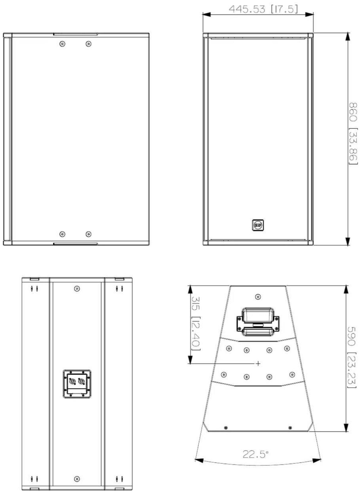
| Size | Height: | 446 mm / 17.56 inches |
| Width: | 860 mm / 33.86 inches | |
| Depth: | 590 mm / 23.23 inches |

- CONTENTS
- ENGLISH
- ITALIANO
- SAFETY PRECAUTIONS AND GENERAL INFORMATION
- IMPORTANT NOTES
- SAFETY PRECAUTIONS
- Power supply from mains
- OPERATING PRECAUTIONS
- CORRECT DISPOSAL OF THIS PRODUCT
- substances
- CARE AND MAINTENANCE
- DESCRIPTION
- Q 15, Q 15-L, Q 15-P - TWO-WAY POINT SOURCE MODULES
- CONNECTIONS
- THE REAR PANEL
- 'BI-AMP' MODE
- CONNECTIONS
- NOTES ABOUT LOW IMPEDANCE CONNECTIONS
- WARNING! CAUTION!
- HORIZONTAL HANGING
- HORIZONTAL HANGING OF 1 SPEAKER
- HORIZONTAL HANGING OF 2 OR MORE SPEAKERS
- HORIZONTAL CONFIGURATIONS
- VERTICAL HANGING
- VERTICAL CONFIGURATIONS
- VERTICAL HANGING WITH A 10° ANGLE
- EXAMPLES OF CONFIGURATIONS
- EXAMPLE
- EXAMPLES OF MIXED CONFIGURATIONS
- AVVERTENZE PER LA SICUREZZA E INFORMAZIONI GENERALI
- Q 15, Q 15-L, Q 15-P - MODULI POINT SOURCE A DUE VIE
- NIZIONE! CAUTELA!
- SOSPENSIONE ORIZZONTALE DI 1 DIFFUSORE
- SOSPENSIONE ORIZZONTALE
- SOSPENSIONE ORIZZONTALE DI 2 O PIÙ DIFFUSORI
- SOSPENSIONE VERTICALE CON ANGOLO DI 10°
Brand : RCF
Model : Q 15
Category : Loudspeaker