KIT-8D - Uncategorized Sanwa - Free user manual and instructions
Find the device manual for free KIT-8D Sanwa in PDF.

| Type | Arcade Joystick Kit |
| Model | KIT-8D |
| Brand | Sanwa |
| Dimensions (base) | 80 mm x 80 mm |
| Height from panel | Approx. 70 mm |
| Weight | Approx. 200 g |
| Construction | High-strength plastic body with metal shaft |
| Switches | 4 x microswitches (Omron or compatible) |
| Directional input | 8-way (up, down, left, right, diagonals) |
| Connector | 5-pin female connector (compatible with JST or similar) |
| Actuation force | Approx. 100 gf (adjustable with spring change) |
| Return mechanism | Rubber grommet centering |
| Mounting type | Panel mount (requires 30 mm hole) |
| Compatible panels | Thickness up to 6 mm |
| Shaft thread | M6 x 0.75 |
| Ball top included | Yes (standard 35 mm acrylic ball) |
| Operating life | Over 1,000,000 actuations |
| Maintenance | Clean with soft dry cloth; avoid liquids |
| Safety | Keep away from water and excessive dust |
| Spare parts | Replaceable microswitches, grommet, spring, shaft, ball top |
Frequently Asked Questions - KIT-8D Sanwa
User questions about KIT-8D Sanwa
0 question about this device. Answer the ones you know or ask your own.
Ask a new question about this device
Download the instructions for your Uncategorized in PDF format for free! Find your manual KIT-8D - Sanwa and take your electronic device back in hand. On this page are published all the documents necessary for the use of your device. KIT-8D by Sanwa.
USER MANUAL KIT-8D Sanwa
Assembling Training for Circuit tester
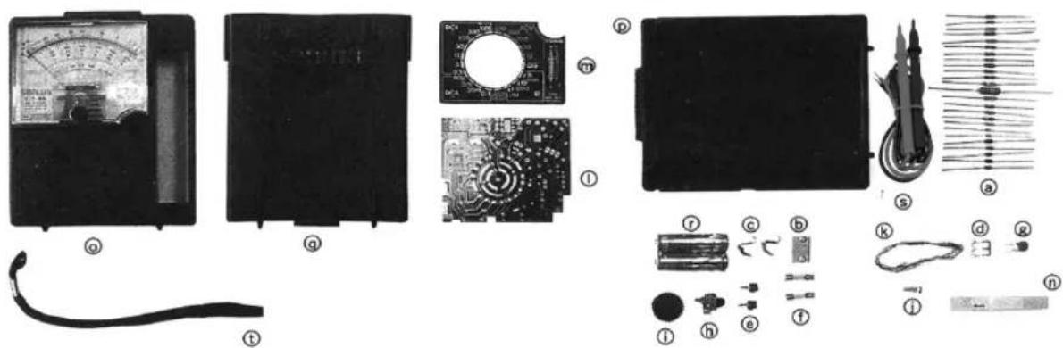
natural_image
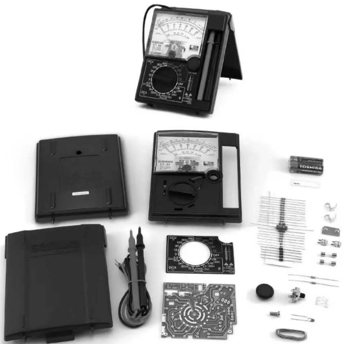
Collection of electronic components including a multimeter, analog meters, and circuit board (no visible text or symbols)Instruction Manual for Assembling and Operation Procedures
Introduction
Thank you very much for purchasing Sanwa Model KIT-8D Analog Multitester Kit.
The KIT-8D is an analog multitester kit that we have developed for educational use through a wealth of our experiences and achievements.
Although primarily designed as a kit, this product provides five modes including voltage and current, as well as high durability, allowing you to use it for a broad range of purposes.
In order to ensure its best performance as a finished product, you need to learn the procedures for properly assembling, adjustment and handling the KIT-8D and making measurements.
Please thoroughly read this manual and make the best use of the KIT-8D.
The instruction manual should be carefully kept along with the KIT-8D.
Contents
I Instruction Manual
1-1 Safety Precaution – read before use 1
1-2 Product Description 2
① Application and Features 2
② Names of Various Parts 2
1-3 Explanation of Functions 3
① Description of Each Function 3
1-4 Measuring procedure 4
① Pre-operation Check 4
② Preparations for measurement 4
③ Measurement of DC Voltage (DCV =) 5
④ Measurement of AC Voltage (ACV \~) 6
⑤ Measurement of DC Current (DCA ≡) 7
⑥ Measurement of Resistance (Ω) 8
⑦ Battery Check (1.5V) 9
⑧ Other Measurements 10
1-5 Maintenance 12
① Service Check 12
② Calibration 13
③ Replacing the fuse and batteries 13
④ Storage 14
1-6 Troubleshooting 15
1-7 Repair Parts 15
1-8 Specifications 16
① General Specifications 16
② Working Range and Tolerance 16
II Basic Knowledge on Testers (Circuit Testers)
2-1 What is a tester? 17
2-2 Principle of a Meter 17
2-3 Structure of a Tester 18
2-4 Ohm's Law 20
2-5 Calculation of Effective Resistance 20
2-6 SI Prefix 21
2-7 Multiplier 21
2-8 Shunt 22
2-9 Rectification Circuit 23
2-10 Principle of an Ohm Meter 24
2-11 Color Code and Rating Code 25
III Tester Assembly
3-1 Properties of Soldering 26
3-2 Soldering Method 26
3-3 Soldering Practice 27
3-4 Preparations for Assembling 27
3-5 Assembling and Wiring 28
IV Operation Test and Calibration
4-1 Quick Operation Check 43
4-2 Calibration of the Tester 45
4-3 Measurement Results 46
4-4 Summary of the Results 47
V Circuit Calculation of the Tester
5-1 Meter Circuit 48
5-2 DCA Circuit 49
5-3 DCV Circuit 49
5-4 ACV Circuit 51
5-5 Ohm Meter (Ω) Circuit 52
5-6 Battery Check Circuit (1.5V) 54
- KIT-8D Type Circuit Diagram 55
VI Assembly of Buzzer Kit (Optional Accessory) 56
- Parts List Sheet 61
I Instruction Manual
1-1 Safety Precaution – read before use
Thank you for buying Sanwa Tester Kit
The contents of ‘For Safe Use’, ‘Measurement’, and ‘Maintenance’ described in these operating instructions are particularly important. Read these items well before use for safe and correct operation. Keep these operating instructions with the product.
Use of the product without reading the operating instructions may result in personal injury including burn and electric shock and destruction of the product. Read this manual before use.
Description of symbols such as Warning
Certainly follow the ‘Warning’ and ‘Caution’ items described in the text. Improper method of use may cause personal injury including burn and electric shock and damage of the product.
- Meaning of the symbols used on the product and in these ‘Operating Instructions’
⚠ (Warning symbol) This indicates items especially important for safe use. Read the description well. The ‘Warning’ describes items to be followed to avoid personal injury while the ‘Caution’ describes items on handling that may damage the product. Be sure to follow the instruction.
(High voltage symbol) Be careful of the impressed high voltage.
(Fuse symbol) Fuse
= (DC symbol) Direct current (DC)
(AC symbol) Alternating current (AC)
- For Safe Use
The items described below are warnings to prevent personal injury such as burns, electric shock, etc.
Be sure to follow the instructions when using the product.
⚠ Warning
- Do not use the device to measure power lines not less than 6kVA.
- Danger of electric shock if the voltage being examined is not less than DC70V or AC33Vrms, 46.7Vpeak. Wear personal insulating protective equipment as required.
- Do not use the device when your hand or the device itself is in wet conditions.
- Be sure to carry out ‘range check’ for each measurement.
- Do not use the device in conditions where the rear case is open or the rear case and its insulating parts are damaged.
- Do not alternate or disassemble the device except for operations instructed in this manual.
- Always use the same rating internal fuses.
-
Use test leads of the specified type.
-
Do not use the test leads when the envelope is damaged; replace the leads with new ones.
- Do not hold the test leads over the brim at the test pin end when measuring.
- Be careful not to apply over-voltage when measuring pulsating waves or waveforms including pulses.
- Check the device at least once a year.
- Do not switch to other ranges during measurement.
- Do not use the product for line measurement such as motors that generate induced voltage or voltage surges.
- The multitester restricts in use in indoor.
1-2 Product description
① Application and features
- Application... This product is a portable learning kit designed for measurement of small-capacity electric circuits. The product is suitable for measurement of small communication devices, household appliances, lamp line voltage and batteries.
- Features...... 1) Equipped with lightweight, small, high-sensitivity and shock resistant-type taut band meter.
2) Basic functions include measurement of DCV, ACV, DCA and . In addition, the battery check range allows inspection of 1.5V-dry battery at an actual load (20 ).
3) Direct-mount test leads ensure no need to worry about missing of leads. Convenient storage space within the main body available.
4) Panel protection cover equipped ; also acts as a stand.
5) Hand strap convenient for carrying.
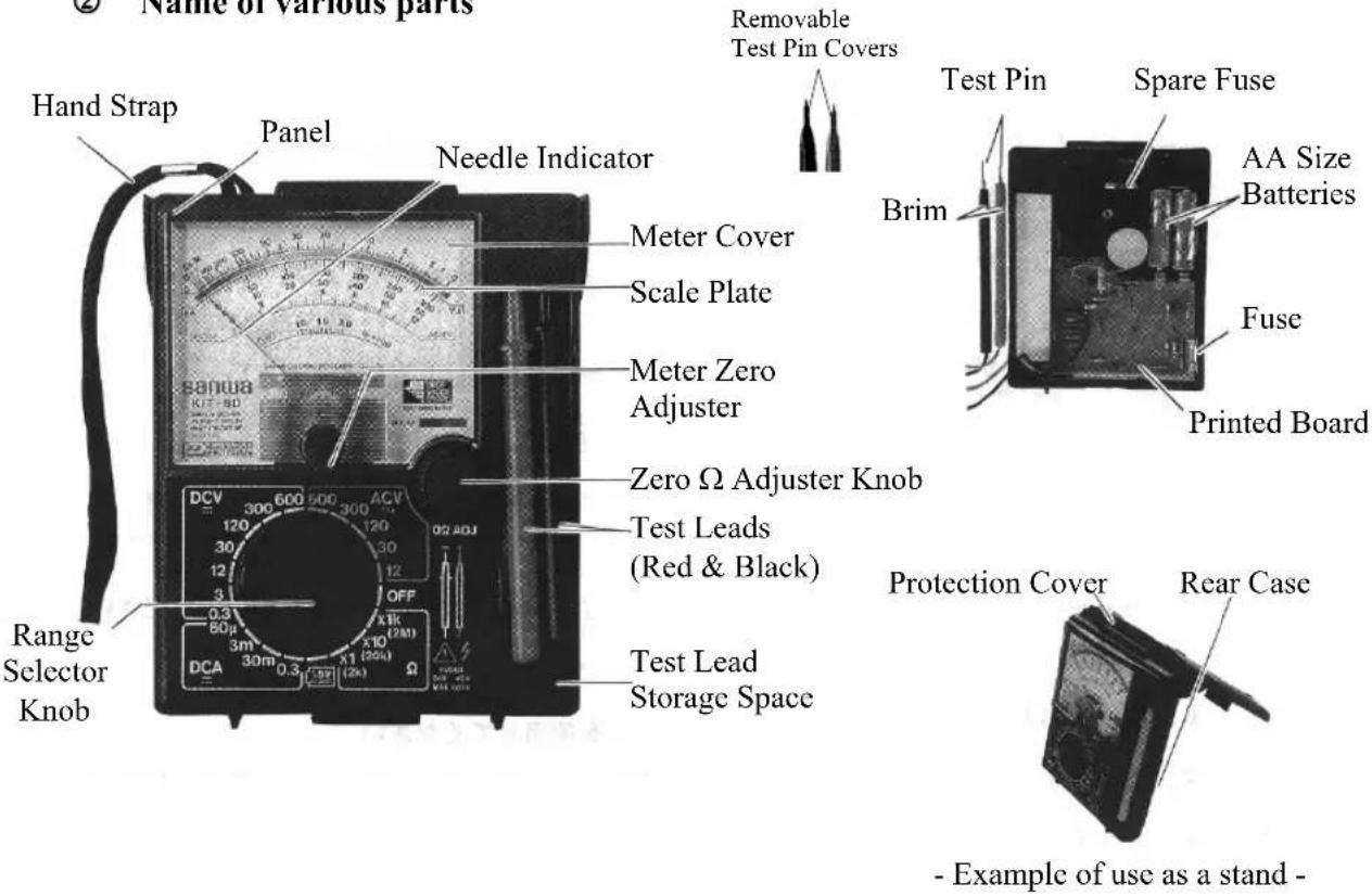
② Name of various parts
• How to read the scale plate

3V× 20k = 60k
Fig 1-1
1-3 Explanation of Functions
① Description of each function
Range selector
This is a switch knob to select measuring functions. Adjust the range selector knob to the range to be examined.
Meter zero adjuster
This is a device to adjust the needle indicator to zero (the left end of the meter scale).
Zero Ω adjuster knob
This is a device to adjust the needle indicator to zero of the scale (the right end of the meter scale) before measurement.
How to use the protection cover
-
Install the cover as illustrated in Fig a; put the cover onto the rear case side or the panel side when you use or do not use the product, respectively. Do not press the cover down from above the main body as shown in Fig b; this will break the cover.
-
Connect the cover as illustrated in Fig c when you use it as a stand. Do not close the cover while it is still connected as a stand; this will break the cover.
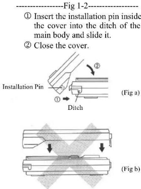
Note) Indication error may become larger if you use the meter in a standing position because the meter is not placed horizontally.
(Fig c) (Fig d)
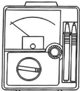
Storage of the test leads
Store the test leads in the storage space as illustrated in the right figure (Fig 1-3) when you do not use the device. How to store : make three small rings with the lead lines, put them into the storage space and then put the test rods into the space, the test pin side first.
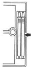
Fig 1-3
1-4 Measuring procedure
① Pre-operation check
⚠ Warning
Always inspect the main body, test leads and fuse before use.
- Check if there is any damage in the appearance due to drop shock, etc. Do not use the product if any damage is found.
- There is a danger of electric shock if the cord of the test leads is damaged or the core wire is exposed. Do not use the product in such conditions.
- Check and ensure that the test leads or the internal fuse is not broken. (See P. 12 'Maintenance' / Internal Fuse, a-(3))
② Preparation before measurement
1) Meter zero adjustment
Turn the zero adjuster of the meter to adjust the needle to zero at the left end of the scale. You do not have to frequently carry out this zero adjustment operation, though you should be careful about zero adjustment because deviation of the needle indicator from the zero point will lead to indication errors. Zero adjustment is a basic procedure and hence important to practice when you use measuring devices. See the figure below for the method.
2) Turn the range selector knob to select the measurement range to be used.
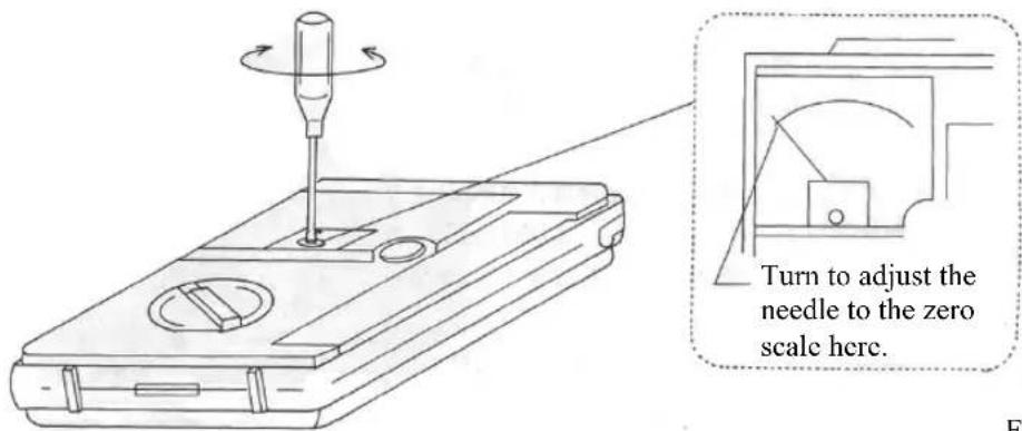
Fig 1-4
⚠ Warning
- Never impress input signals that exceed the maximum measurable voltage of each range.
- Be sure to carry out 'range check' for each measurement.
- Do not switch to other ranges during measurement.
- Never carry out measurement when your hand is wet.
- Do not hold the test leads over the brim at the test pin end when measuring.
1) Objects to be measured
Direct current voltage including general battery cells, radios, amplifiers, etc.
2) Measurement range
7 ranges : 0.3/3/12/30/120/300/600V
3) Measurement method
Connect the meter in parallel with the circuit. Be sure to connect to the correct polarity during measurement of direct current voltage. (The needle will swing backwards if the connection is reversed.) The illustrations below show how to do this:
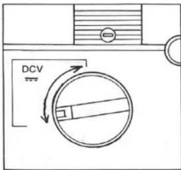
- Adjust the range selector knob to the optimal range among the DCV ranges.
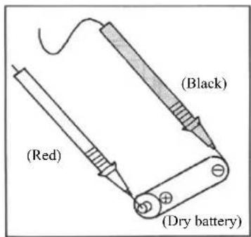
- Connect the red and black test pins to the plus and minus sides, respectively, of the object being examined.
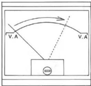
- Read the scale deflection by the V.A scale.
-Fig 1-5
Memo
The ‘optimal range’ means the range where the needle indicator points the scale as near to the maximum as possible (right-hand side) to achieve high accuracy of the readout. (Select the range that is larger but also near to the value to be examined, e.g. choose 3V-range for measurement of 2V, 12V-range for measurement of 10V, etc.)
Try the maximum range (600V) first if you cannot guess the approximate value.
④ Measurement of AC voltage (ACV)
Measurable voltage : max. AC600V
⚠ Warning
- Never impress input signals that exceed the maximum measurable voltage of each range.
- Be sure to carry out 'range check' for each measurement.
- Never carry out measurement when your hand is wet.
- Do not switch to other ranges during measurement.
- Do not hold the test leads over the brim at the test pin end when measuring.
1) Objects to be measured Tap voltage of small power transformers, voltage of lamp lines, etc.
2) Measurement range Five ranges: 12/30/120/300/600
3) Measurement method Connect the meter in parallel with the circuit. The polarity of the power source does not affect the readout in AC voltage measurement. The illustrations below show how to do this:
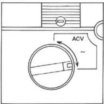
- Adjust the range selector knob to the optimal range among the ACV ranges.
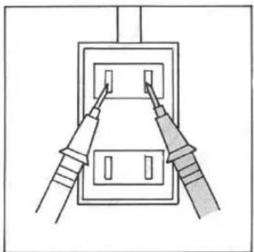
natural_image
Diagram of two connectors inserted into a socket socket (no text or symbols)- Connect the test pins to the object being examined.
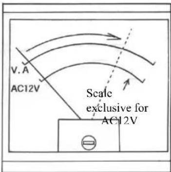
- Read the scale deflection by the V.A scale. (Use the AC12V scale for AC12V range measurement.)
Fig 1-6
Note ● Effect of waveform : Errors occur in measurement of waveforms other than sine wave.
● Effect of frequency : Errors will be larger for higher frequencies.
Use the meter within the frequency range of 30Hz - 50kHz (AC12V range).
⑤ Measurement of DC current (DCA)
Measurable current : max. DC0.3A
⚠ Warning
- Do not impress voltage to the current measurement range. It may cause burns or electric shock.
- Never apply input signals to the input terminal that exceed the maximum measurable current.
- Always connect in series with the circuit.
- Be sure to carry out 'range check' for each measurement.
- Use the device only for low-current circuits.
- Never carry out measurement when your hand is wet.
- Do not switch to other ranges during measurement.
1) Objects to be measured Electric current of circuits that include batteries, rectification circuits, etc.
2) Measurement range 4 ranges : 60μ /3m/30m/0.3A
3) Measurement method Connect the meter in series with the circuit. Be sure to connect the correct polarity during measurement of direct current voltage. The illustrations below show how to do this :
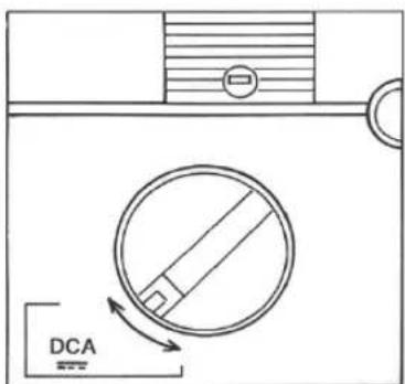
- Adjust the range selector knob to the optimal range among the DCA ranges.
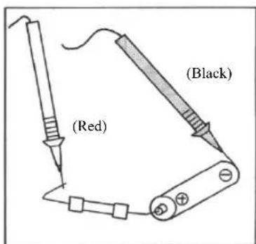
- Turn off the power of the circuit to be measured; break the circuit. Connect the red and black test pins to the plus and minus sides, respectively.
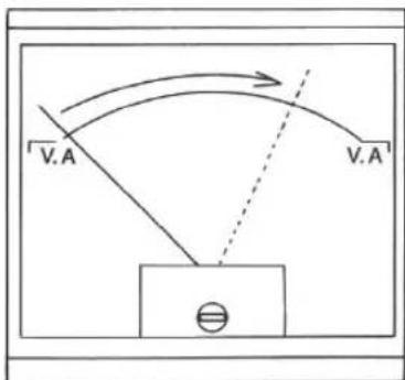
- Turn on the power of the circuit to be measured. Read the scale deflection by the V.A scale.
-Fig 1-7-
Note ● Since the internal resistance of the current range is included in series in current measurement, the current will be reduced by this amount. This effect will be larger in lower-resistance circuits.
⚠ Warning
- Never impress voltage at resistance range.
- Be sure to carry out 'range check' for each measurement.
- Circuits to which voltage is applied cannot be measured.
- Never carry out measurement when your hand is wet.
- Do not switch to other ranges during measurement.
1) Objects to be measured
Resistance measurement of fixed resistors, check of wiring connection and wire breakage
2) Measurement range
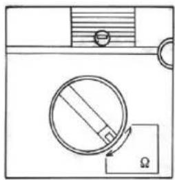
3 ranges : × 1/×10/×1k
3) Measurement method
See the illustrations below :
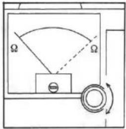
natural_image
Diagram of a mechanical device with a circular component and a rectangular block, no text or symbols present.- Adjust the range selector knob to the range so that the needle indicator points around the center of the scale.
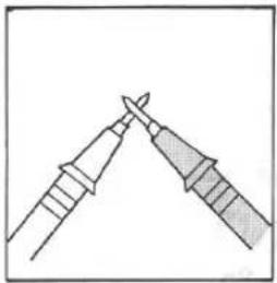
natural_image
Diagram of two pointed tool tips (no text or symbols)- Short-circuit the test pins together.
- While the test pins are sill short-circuited, turn the zero adjuster knob to adjust the needle to zero of the scale.
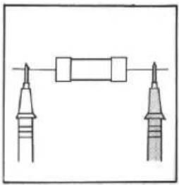
natural_image
Pure electrical circuit lines without any symbols- Connect the test pins to the object to be examined.
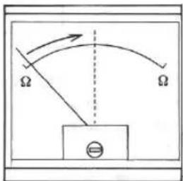
- Read the scale deflection by the scale.
----Fig 1-8----
Memo • 0 Ω adjustment
'Zero Ω adjustment' is a procedure to be carried out prior to measurement of resistance in order to adjust the needle indicator to the zero graduation of the Ω scale (the right end of the scale) by turning the zero Ω adjuster knob while the test pins are short-circuited. Carry out 0 Ω adjustment each time you switch the range ; do it at a suitable time for continuous measurement.
- The needle indicator may not reach the 0 Ω graduation when you turn the zero Ω adjuster knob to fully right during zero Ω adjustment. This suggests that the internal batteries are consumed. Replace the internal batteries.
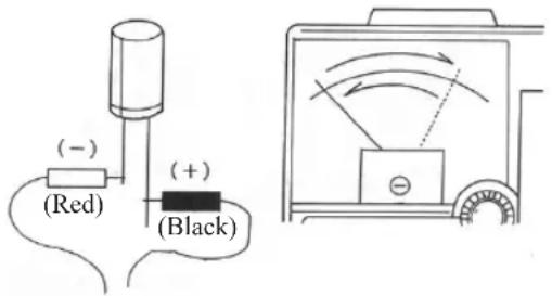
- Polarity of the tester during resistance measurement For resistance range, as seen in the circuit diagram, the red test lead becomes minus while the black test lead becomes plus.
- Errors occur because of the effect of the resistance of human body if you perform measurement with your finger touching to the test pins (especially for ×1k range).
- Resistance of fuse
- Errors occur because of the effect of the resistance of human body if you perform measurement with your finger touching to the test pins (especially for × 1k range). - Resistance of fuse
Zero adjustment may be impossible at ×1 range or measurement accuracy may be reduced because of fuse resistance when you use a fuse lower than the rating (0.5A) or a fuse filled with arc-extinguishing medium.
Always use a fuse of the same rating and specifications.
⑦ Battery check (1.5V)
Load resistance RL = 20Ω
⚠ Warning
- Be sure to carry out 'range check' for each measurement.
- Do not switch to other ranges during measurement.
1) Objects to be measured Manganese dry batteries (SUM-1 / R20, SUM-2 / R14, SUM-3 / R6), alkaline batteries (LR20, LR14, LR6), etc.
2) Measurement range One range : 1.5V / RL = 20Ω
3) Measurement method Voltage is measured by connecting the load resistance to the battery to draw the current of that instant. This allows examination at nearly the same conditions as in use. See the illustrations below for the measuring procedure :
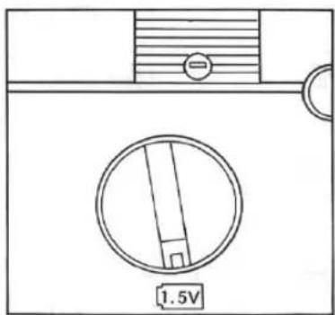
- Adjust the range selector knob to the battery check range.
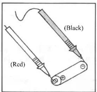
- Connect the red and black test pins to the plus and minus sides, respectively, of the object being examined.
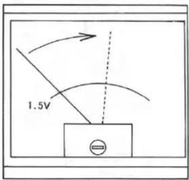
- Read the scale deflection by the battery check scale.
-Fig 1-9
Note - Do not measure voltage of button cell batteries that have small current capacities; the load is too much for these.
- A voltage value of 0.9 to 1.6V can be judged as good for batteries in general. Note that the value judged as good varies in accordance with the device the batteries are used for.
⑧ Other measurements
An easy way of checking electronic components using the range is introduced here. You can also check operation of each electronic component. See the following description for reference:
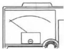
a) Check of a diode
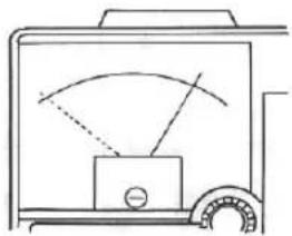
The following procedures enable judgement of quality of a diode. For non-defective diodes, the meter will show a large deflection in the forward direction while deflection in the reverse direction will be negligible. For reference, the figures here show each condition when you check a diode.
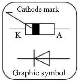
How to check
Adjust the measurement range to ×10 or ×1k and then carry out zero Ω adjustment. Connect the test pins as shown in the figures and read the deflection of the needle indicator to judge if the diode is good or defective.
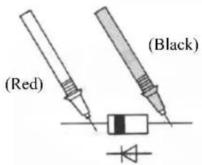
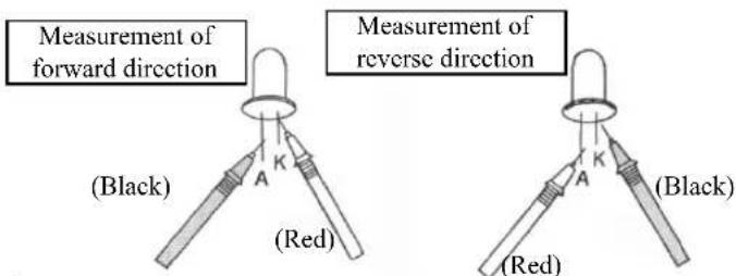
Measurement of forward direction
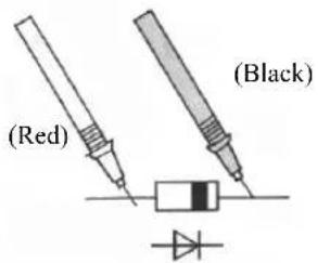
Measurement of reverse direction
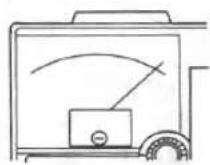
Judgement
____ Deflection of the needle indicator for forward direction ---- Deflection of the needle indicator for reverse direction
The position of the needle : left side : direction ; right side: 0 direction
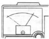
Non-defective
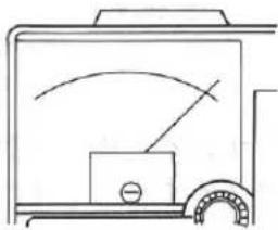
Short-circuit the position of the needle is as in the figure for both forward and reverse directions
Wire breakage the position of the needle is as in the figure for both forward and reverse directions
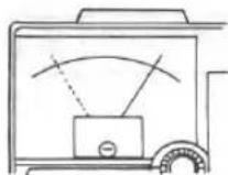
Deteriorated
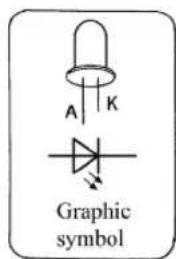
b) Check of a light emitting diode (LED)
The procedures described in a) for check of a diode can also be applied to the check of an LED.
The measurement range for light emission by an LED is somewhat different.
How to check
Adjust the measurement range to ×1 or ×10 and then carry out zero Ω adjustment. Connect the test pins as shown in the figures and read the deflection of the needle indicator to judge if the LED is good or defective.
Note) Check the capacity of LED for caution that the forward current value in the LED does not exceed the maximum rating of the LED.
• Measured voltage: Approx. 3 V (internal batteries)
- Internal resistance: 20 (x1), 200 (x10)
Judgement
Deflection of the needle indicator for forward direction Deflection of the needle indicator for reverse direction
The position of the needle : left side : direction ; right side : 0 direction
natural_image
Simple line drawing of a mechanical device with no text or symbolsNon-defective light will be emitted at forward direction
natural_image
Simple line drawing of a device with a curved arc and a meter (no text or symbols)Short-circuit light will not be emitted in either forward or reverse directions
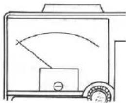
natural_image
Simple line drawing of a vehicle front view with a curved arrow indicating direction (no text or symbols)Wire breakage light will not be emitted in either both forward or reverse directions
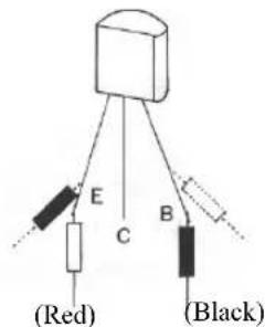
c) Check of a transistor
The range offers an easy way also for judgement of the quality of a transistor.
See the following description for the method of judgement.
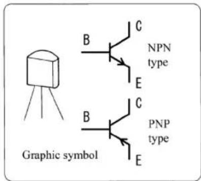
How to check
Adjust the measurement range to ×1k and then carry out zero adjustment. Connect the test pins to the transistor being examined as shown in the figures.
- Check between B and C -
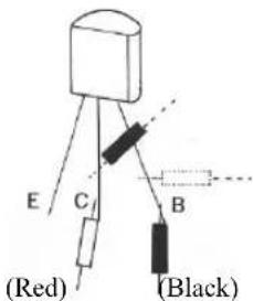
- Check between B and E -
Judgement
For NPN transistors :
- The transistor is in good condition if the needle indicator is deflective during measurement in the direction shown in the solid lines while it does not move during measurement in the direction shown in the broken lines (for both of B-C and B-E check procedures).
For PNP transistors :
- The transistor is in good condition if the needle indicator is deflective during measurement in the direction shown in the broken lines while it does not move during measurement in the direction shown in the solid lines (for both of B-C and B-E check procedures).
d) Check of a capacitor
The meter also offers a way to check relatively large-capacity capacitors such as electrolytic capacitors.
When the test pins are connected, the needle indicator will move because of the charging current of the capacitor and then return gradually to the origin. The needle indicator will twitch only slightly for an instant when you check a small-capacity capacitor since the charging current of the capacitor is small.
Check of a capacitor should be performed after discharging it. (Short-circuit the terminal of the capacitor.)
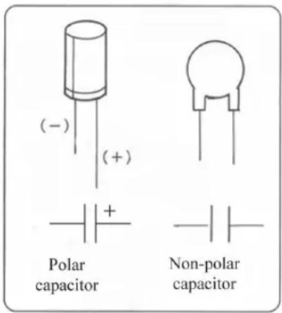
How to check
Connect the test pins to both the electrodes of the capacitor. (Connect the black test pin to the plus side and the red test pin to the minus side of the capacitor.) Use the measurement range that allows the needle indicator to swing far to the right side. The capacitor is normal if the needle indicator moves once and then comes back near to the .
1-5 Maintenance
⚠ Warning
Do not open the rear case unnecessarily, except for the operations needed for maintenance described in the instruction manual.
① Service check
⚠ Warning
- Appearance : Check if there is any damage in the appearance due to drop shock, etc. Do not use the meter if any damage is found.
- Test leads : There is a danger of electric shock if the cord of the test leads is damaged or the core wire is exposed. Do not use the meter in such conditions.
- Internal fuse : Check and ensure that the internal fuse is not blown out. See below for checking procedures.
● Procedures to check the internal fuse
1 Adjust the range selector knob to × 1k of the range.
2 Short-circuit the test pins.
3 The fuse is normal if the needle moves; the fuse may be blown out if the meter does not respond. Replace the fuse with the spare fuse included in the main body and repeat the procedures once more.
② Calibration
⚠ Warning
Check and calibrate the product at least once a year for safety and maintenance of accuracy. Inquire with the distributors or the selling agencies to request check up and calibration.
③ Replacing the fuse and batteries
Warning
- Do not remove the rear case except when you replace the fuse or the internal batteries in accordance with the procedures described in this manual.
- Always make sure before following the procedures that the test pins are not connected to the circuit to be measured.
- Use a fuse of the same rating for replacement. Never use a fuse of other ratings. Never short-circuit the fuse holder terminals with copper wire or other materials.
1) Replacement of the batteries
When the internal batteries are consumed, you cannot adjust the needle indicator to zero in zero adjustment procedure even if you turn the zero adjuster knob fully to the right at range. If you find out that zero adjustment is impossible, replace the internal batteries.
How to replace the batteries
☐ Remove the protection cover installed on the main body.
2 Unscrew the case stopper screw and remove the rear case.
3 Take out the consumed batteries and replace them with new ones. Be sure to put the batteries stably into the battery holder in correct polarity (+ and -).
4 Put the rear case onto the panel and screw the case stopper screw.
5 Put the protection cover back onto the main body.
Note • Use the batteries specified for the product
(Two AA dry batteries UM-3/R6)
- Insert batteries in accordance with the direction (polarity) indicated on the panel.
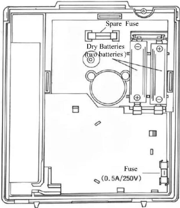
2) Replacement of the fuse
⚠ Warning
Use a fuse of the same rating for safety and maintenance of performance.
(Place an order to our company if it is difficult to obtain.)
The rating of the fuse used
0.5A/250V (5.2 mm in diameter, 20 mm length, in a glass tube ; rupturing capacity : 300A)
If you impress lamp line voltage (100V) etc. to , DCA, or battery check range by mistake, the fuse will blow out to protect the circuit.
The main cause that the needle indicator never twitches during the procedures to make the needle move at range is a blown-out fuse.
How to replace the fuse
1 Remove the protection cover installed on the main body.
2 Unscrew the case stopper screw and remove the rear case.
3 Remove the blown-out fuse from the fuse holder; replace it with a new one.
4 Put the rear case onto the panel and screw the case stopper screw.
5 Check if the indication of each range is normal.
6 Put the protection cover back onto the main body.
● Use the spare fuse included in the main body.
④ Storage
Caution
- The meter cover is treated with antistatic treatment. Do not rub hard with a cloth or other materials. In the case that charge is built up after many years of use, temporary measures may be effective: apply neutral detergent diluted several times with water onto the surface of the cover.
- Avoid vibration such as loading on a motorbike; the meter may fail to operate.
- Do not leave the device for a long time under direct sunlight, at high temperature ( > = 60^ ), high humidity ( > = 85% ) or under the conditions in which dew will condensate.
- Do not use thinners or alcohols for cleaning of the device. Wipe the dust off lightly with a soft brush or a cloth.
1-6 Troubleshooting
Check the following items before sending out this instrument for repair :
| Status Checkpoint | Treatment | |
| No indication for all the ranges (The indicator does not move at all) | Has the fuse been blown out? | Replace the fuse. |
| Has the test lead been broken? | Make a request of repair to our company. | |
| Indication for Ωrange not availableZero Ω adjustment impossible | Has the internal batteries been consumed? | Replace the internal batteries. |
1-7 Repair parts
- Replacement fuse (0.5A / 250V, 5.2 mm in diameter, 20 mm length, in a glass tube; rupturing capacity : 300A)
Place an order to the Customer Support of our company for replacement fuses : specify the model of the product and the name of the parts.
Inquiries
Make inquiries to our company for questions about the product :
Tokyo Headquarter : TEL (03) 3251-0941 FAX (03) 3256-9740
E-mail : exp_sales@sanwa-meter.co.jp
Web site of Sanwa Electric Instrument Co., Ltd.: http://www.sanwa-meter.co.jp
1-8 Specifications
① General Specifications
| AC Recrifier Form | Half-wave rectifier form |
| Meter type | Internal magnet type. Taut band meter |
| Accuracy Assurance Temperature / Humidity range | 21 ~ 25°C 75%RH max. No condensation |
| Operating Temperature | 3 ~ 43°C 80%RH max. No condensation |
| Storage Temperature | -10 ~ 50°C 70%RH max. No condensation |
| Environmental condition | Altitude 2000m or below, pollution degree II |
| Circuit Protection | Protection by the fuse and the diode is available against impression of voltage not exceeding the commercial power supply, AC200V, to all the range for a duration of 5 seconds. (Repeated impression may deteriorate the diode.) |
| Frequency Characteristics 30 - 50kHz (AC12V range) | |
| Internal Batteries | Two AA size manganese dry batteries UM-3(1.5V) |
| Internal Fuse | Two fuses (one for spare) ; 0.5A / 250V, 5.2 mm in diameter, 20 mm length, in a glass tube ; rupturing capacity : 300A |
| Accessories | Operating instruction manual |
| Optional Accessories | Piezoelectric buzzer kit |
| Size & mass | 159.5 × 129 × 41.5 mm, ca. 320 g |
② Working range and tolerance
| Measurement function | Measurable range Tolerance | |
| DC voltage (DCV) | 0.3V (internal resistance : 16.7kΩ/V)3/12V (internal resistance : 20kΩ/V)30/120/300/600V (internal resistance : 9kΩ/V) | Within ± 3% of the maximum scale |
| AC voltage (ACV) | 12/30/120/300/600V (internal resistance : 9kΩ/V) | Within ± 4% of the maximum scale |
| DC current (DCA) | 60μ/3m/30m/0.3A(voltage drop across the terminals : 0.3V(Note) : fuse resistance not included)(5kΩ/100.5Ω/10.5Ω/1.5Ω) (internal resistance)(Note) : fuse resistance included | Within ± 3% of the maximum scale |
| Resistance (Ω) | ×1/×10/×1k(20Ω/200Ω/20kΩ)(graduation at the middle of the scale) | Within ± 3% of the scale length |
| Battery check | D, C, AA, and AAA size batteries(load resistance : 20Ω) | ---- |
Note) Tolerance warranty conditions :
• Temperature : 23 ± 2^
• Humidity : 45 - 75%
- Posture : horizontal ( ± 5^ )
- Sine wave for AC range (50Hz or 60Hz)
II Basic knowledge on testers (Circuit testers)
2-1 What is a tester?
A tester (circuit tester), as the name suggests, is a measuring instrument designed to be very convenient for the check of circuits. The device has a structure that enables vast varieties of measurement including voltage, electric current and resistance by change of connection of the test leads or switching of the rotary switch, though it is not suitable for precise measurement in view of circuitry. In simple terms, it is like a stethoscope that physicians use. The point of difference from a stethoscope is that a tester clearly expresses in the form of a numerical value the electricity that cannot be usually seen. Since there is no need for precise measurement in testing of general electric circuits except for special cases, a tester is good enough for circuit check even though it has relatively large indication errors (tolerance).
2-2 Principle of a meter
A meter is a device that converts an electrical quantity (voltage, current and resistance) into a mechanical quantity. A simple explanation is made here using Fig 2-2: When an electric current is applied to the coil placed in the magnetic field of the permanent magnet NS, the coil will rotate in the direction shown by F and F' according to Fleming's left-hand rule illustrated in Fig 2-3. The control spring will work so that it swings at an angle in direct proportion to the electric current and hence the quantity of the current applied will be indicated in a scale of linear rotation angle. Meters that use the principle described above are called moving-coil meters.
This principle suggests that strength of the permanent magnet, number of turns of the coil and strength of the control spring are important elements for a meter.
There are different methods to support the moving coil : Fig 2-1 (a) illustrates the pivot suspension that uses a pivot and a jewel, while (b) designates the taut band suspension system that uses a taut band to support the coil. The moving-coil meters are classified into two categories according to the position of the permanent magnet : external or internal. An external magnet meter has a permanent magnet outside of the moving coil, while an internal magnet meter has it inside. Internal magnet meters have high magnetic efficiency and, since they do not require any pole piece, they can be constructed small and lightweight ; operation of the close ring prevents magnetic field interference. External magnet meters can adopt large magnets and are suitable for high-sensitivity models.
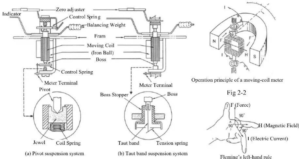
Fig 2-1 Meter Structure
Fig 2-3
2-3 Structure of a tester
A tester consists basically of the meter unit that indicates the electric charge, the resistor unit that magnifies the scale, the rectifier unit (diodes) that converts alternating current into direct current, and the battery unit that supplies power for measurement of resistance.
Circuit components such as diodes and fuses are combined in addition to the units described above as protection circuits in view of safety.
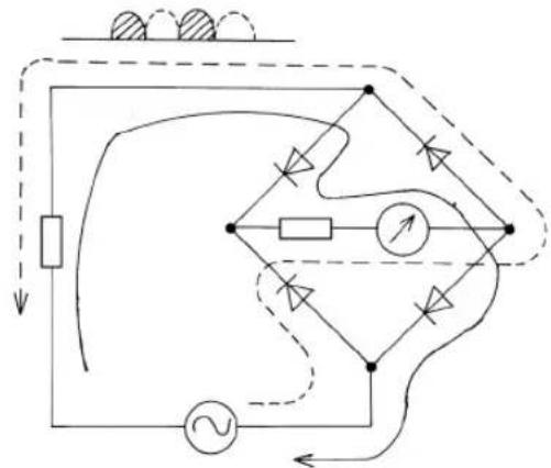
① Rectifier (Diode)
The direction of the alternating current is reversed periodically. Since the deflection of the two opposite directions cancel each other, a moving-coil meter will hardly operate. A rectifier has the role to convert the alternating current into direct current by passing only one direction of the alternating current.
Silicone diodes are usually used for rectifiers because of favorable frequency characteristics and reverse breakdown voltage. An exclusive set of scale marks is devised for the AC12V range in this product.
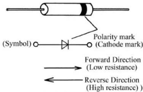
Fig 2-4
The reason for this is that, because the resistance of the multiplier is low at a low voltage range, the resistance change of the rectifier that is connected in serial with the multiplier (which changes in accordance with the amount of the electric current) will be greatly affected. The indication is not affected at higher voltage range because the resistance of the multiplier is large and hence the change can be neglected.
② Battery (Manganese dry cell)
The batteries used in a tester will operate as an electric power supply required for resistance measurement.
A small tester usually uses one or two UM-3 type (1.5V) dry cells (1.5V - 3V). Since the higher voltage of the batteries enables measurement of higher resistance, some high-class testers adopt S-006P (9V) layer-built dry cells.
The voltage of a new battery is usually about 1.65V, higher by around 10% compared to the value indicated (1.5V). Also, a new layer-built dry cell usually has a higher voltage, about 10V, compared to the indicated value, 9V.
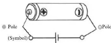
Fig 2-5
③ Resistor
Metal film resistors are widely used in testers because of good accuracy and temperature characteristics.
The recent trend of miniaturization and densification has introduced many chip resistors that have no lead wires. The components of testers have become more of the chip-type in recent years.
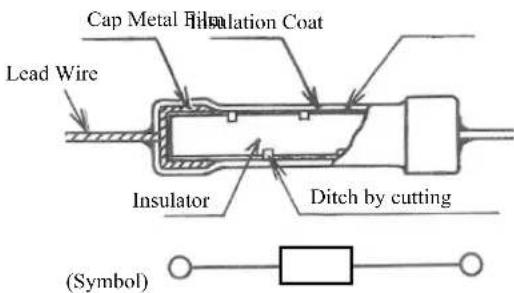
Fig 2-6
④ Zero Ω adjuster
A carbon variable resistor is used for the zero adjuster. The variable resistor of a tester has a role to minimize measurement errors by compensating the voltage change (wear and tear) of the internal batteries with a circuit.
⑤ Capacitor
Capacitors used in testers have the property that they pass alternating current while they do not pass direct current and are used frequently in cases where low frequency output is measured. The capacitor in the protection circuit of this product is incorporated as a by-pass capacitor to prevent the effect of high frequency.
Other than this, capacitors also have the property to accumulate electricity and are widely used in electric circuits as well as resistors.
⑥ Meter protection diode
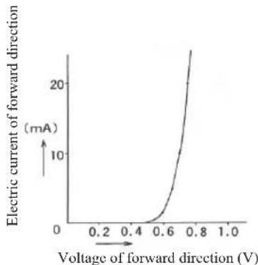
Silicon diodes have the property that they start to conduct electric current at 0.5 - 0.6V and higher voltage at room temperature as shown in Fig 2-9. This property is used for protection of the meter. In normal measurement, the electric current will not go through the diode. (Electric current passing through the diode will be the source of inaccuracy.) When the current is overloaded, the voltage between the terminals of the meter will rise and the diode in parallel with these will conduct the electricity. Most of the electric current will pass through the diode and the meter will thus be protected from damage.
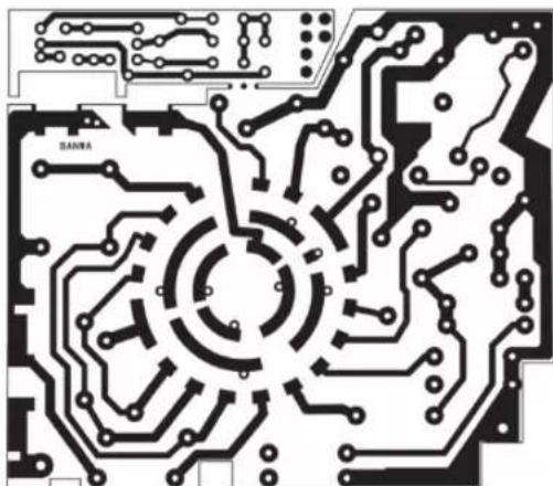
⑦ Printed board
There are several kinds of printed boards : bakelite boards, paper epoxy boards, glass epoxy boards, etc. Bakelite boards of 1.6 mm thickness are generally used for testers.
In the case of testers, they have considerable effect on simplification of the circuit wiring because they also have the function of switch contact. There are, however, problems such as dielectric strength and leak current. This product is designed considering safety; the board is coated with solder resist (green coating) and is split where needed. Nevertheless, you should still take care not to touch the printed side of the board with a dirty hand to prevent leakage.
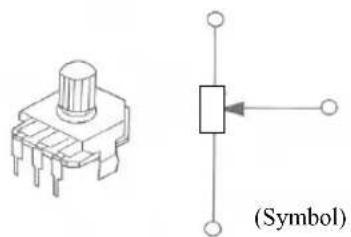
natural_image
Pure electrical component diagram showing a push-button switch and a rectangular symbol with arrow (no text or labels)Fig 2-7
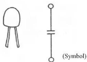
natural_image
Simple line drawing of a mushroom-shaped object and a capacitor symbol (no text or labels)Fig 2-8
line
| Voltage of forward direction (V) | Electric current of forward direction (mA) | | -------------------------------- | ------------------------------------------ | | 0.0 | 0 | | 0.2 | 0 | | 0.4 | 0 | | 0.6 | 5 | | 0.8 | 20 | | 1.0 | 25 |Fig 2-9
natural_image
Pure electrical circuit lines without any symbolsFig 2-10
2-4 Ohm's law
An understanding of Ohm's law and calculation of effective resistance will provide understanding of the circuit of a tester to some extent. Three equations shown below express the relationship between electric quantities, i.e. voltage E [V], current I [A], and resistance R [Ω]:
$$ \begin{array}{l l} \mathrm{I} = & \frac {\mathrm{E}}{\mathrm{R}} \ R = & \frac {E}{I} \ E & I \bullet R \end{array} \quad \dots\dots (1) \tag {2} $$
I : Current [A]
E : Voltage [V]
R : Resistance [Ω]
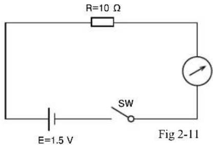
[Example 1] How much current will flow when the SW is turned on in Fig 2-11?
(Answer) From the Ohm's law,
$$ \mathrm{I} = \frac {\mathrm{E}}{\mathrm{R}} [ \mathrm{A} ]; $$
E = 1.5V, R=10Ω; and hence
$$ \mathrm{I} = \frac {\mathrm{E}}{\mathrm{R}} = \frac {1 . 5 \mathrm{V}}{1 0 \Omega} \quad 0. 1 5 [ \mathrm{A} ] $$
2-5 Calculation of effective resistance
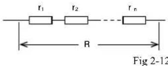
(a) Serial Connection
$$ \mathrm{R} = \mathrm{r} _ {1} + \mathrm{r} _ {2} + \dots \dots \mathrm{r} _ {\mathrm{n}} \quad \dots \tag {4} $$
(b) Parallel Connection
$$ \frac {1}{R} = \frac {1}{r _ {1}} + \frac {1}{r _ {2}} + \dots \dots . \frac {1}{r _ {n}} $$
$$ \therefore R = \frac {1}{\frac {1}{r _ {1}} + \frac {1}{r _ {2}} + \dots \dots . \frac {1}{r _ {n}}} \quad \dots \tag {5} $$
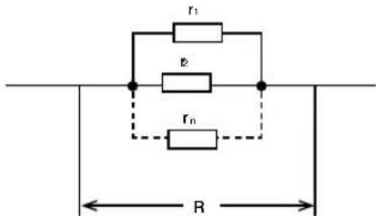
Fig 2-13
A generally used model, connection of two resistors, is expressed as below by transforming
$$ R = \frac {1}{\frac {1}{r _ {1}} + \frac {1}{r _ {2}}} $$
$$ R = \frac {r _ {1} \times r _ {2}}{r _ {1} + r _ {2}} \tag {6} $$
$$ \text { or } \quad r _ {1} = \frac {r _ {2} \times R}{r _ {2} - R} \tag {7} $$
[Example 2]
How much is the effective resistance of the right figure (Fig 2-14)?
$$ \mathrm{r} _ {1} = 1 0 \Omega , \quad \mathrm{r} _ {2} = 2 0 \Omega , \quad \mathrm{r} _ {3} = 3 0 \Omega $$
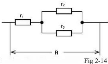
(Answer) r_2 and r_3 are connected in parallel; these are connected to r_1
$$ R = r _ {1} + \frac {r _ {2} \times r _ {3}}{r _ {2} + r _ {3}} = 1 0 \Omega + \frac {2 0 \Omega \times 3 0 \Omega}{2 0 \Omega + 3 0 \Omega} = 1 0 \Omega + 1 2 \Omega = 2 2 [ \Omega ] $$
2-6 SI prefix
Prefixes are used in the indication and calculation of electric quantities such as voltage [V] when it is not easy to handle numbers too large or too small. It is important to adopt the same unit when calculating.
Use of exponential expressions (e.g. 4.1 × 10^3 ) is also required.
| Prefix | M | k | n | p | ||
| Reading | mega- | kilo- | milli- | micro- | nano- | |
| Multiple | 10^6 | 10^3 | 10^-3 | 10^-6 | 10^-9 | 10^-12 |
| Example | 1.8M =1800k | 4.1k =4100 | 25mA=0.025A | 50 A=0.05mA | 200nF=0.2 F | 1000pF=0.001 F |
[Example 3] How much is 200 A in amperes? How much in milliamperes?
(Answer)
From the table, ' means 10^6 . And hence
$$ 2 0 0 \mu \mathrm{A} = 2 0 0 \times 1 0 ^ {6} [ \mathrm{A} ] = 2 \times 1 0 ^ {2} \times 1 0 ^ {- 6} [ \mathrm{A} ] = 2 \times 1 0 ^ {4} [ \mathrm{A} ] = 0. 0 0 0 2 [ \mathrm{A} ]. $$
means 10^-6 while mA means 10^-3 ; the difference is 10^-3 . And hence
$$ 2 0 0 \mu \mathrm{A} = 2 0 0 \times 1 0 ^ {3} [ \mathrm{mA} ] = 2 \times 1 0 ^ {2} \times 1 0 ^ {3} [ \mathrm{mA} ] = 2 \times 1 0 ^ {1} [ \mathrm{mA} ] = 0. 2 [ \mathrm{mA} ]. $$
[Example 4] How much voltage [V] does the battery E have in the circuit shown in Fig 2-15?
(Answer)
The effective resistance R is :
$$ R 5 k = + \frac {2 0 k}{2 0 k \Omega + 2 0 k \Omega} \times = \quad \Omega k $$
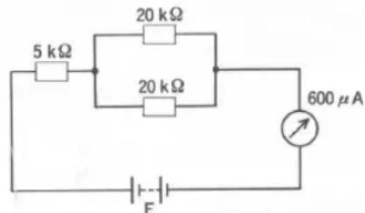
Fig 2-15
From Ohm's law,
$$ \mathrm{E} = 1 \bullet \mathrm{R} = \underbrace {6 0 0 \times 1 0 ^ {6} \mathrm{A}} _ {\text { }} \underbrace {\times 1 5 \times 1 0 ^ {3} \Omega} _ {\text { }} = 6 \times 1 0 ^ {3} \times 1 0 ^ {- 6} \times 1 5 \times 1 0 ^ {3} \mathrm{V} = 9 0 \times 1 0 ^ {1} \mathrm{V} = 9 [ \mathrm{V} ] $$
Calculate by using the same unit for [A] and [Ω].
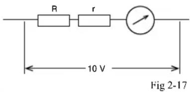
2-7 Multiplier
E : voltmeter before multiplying [V]
E_0 : voltmeter after multiplying [V]
R : resistance of the multiplier [Ω]
r : internal resistance of the meter [Ω] (resistance of the coil)
I : current sensitivity of the meter [A]
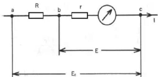
Fig 2-16
In Fig 2-16, for the circuit between b and c, the next expression is true from Ohm's law (1):
$$ \mathrm{I} = \frac {\mathrm{E}}{\mathrm{r}} \dots \tag {8} $$
For the circuit between a and c, from the Ohm's (3),
$$ \mathrm{E} _ {0} = I \bullet (R + r) \dots \tag {9} $$
Substitution of (8) into (9) gives
$$ \mathrm{E} _ {0} = \frac {E}{r} \bullet (R + r) \dots \tag {10} $$
Transformation of (10) gives
R (E0 E0(E·)/V. ..... (11)
From (10),
$$ R = r \bullet \left(1 \frac {\mathrm{E} _ {0}}{E} -\right) \dots \tag {12} $$
We can obtain the following equation by defining that
_0E=n (where “n” is the magnification factor):
$$ R = r \bullet (n - 1) \dots \tag {13} $$
[Example 5] How much resistance is needed for R to obtain a 10V-voltmeter from a meter of 500 A-500 as shown in Fig 2-17?
(Answer) Substituting into (13) gives
$$ \mathrm{n} = \frac {\mathrm{E} _ {0}}{\mathrm{E}} = \frac {1 0 \mathrm{V}}{(5 0 0 \times 1 0 ^ {- 6} \mathrm{A}) \times 5 0 0 \Omega} = 4 0 $$
$$ R = r \cdot (n - 1) = 5 0 0 \Omega \times (4 0 - 1) = 1 9 5 0 0 [ \Omega ] = 1 9. 5 k \Omega $$
2-8 Shunt
The current I in Fig 2-18 is expressed as follows from Ohm's law (1): I =
Transformation gives: E = I • r ..... (14)
From Ohm's law (1) and the equation for resistors in parallel connection (5), I_0 is expressed as follows :
$$ I _ {0} = \frac {E}{\frac {1}{\frac {1}{r} + \frac {1}{R}}} = E \cdot \left(\frac {1}{r} + \frac {1}{R}\right) \dots \tag {15} $$
By substituting (14) into (15), we obtain :
$$ I _ {0} = I \bullet r \bullet \left(\frac {1}{r} + \frac {1}{R}\right) = I \bullet \left(1 + \frac {r}{R}\right) \quad \dots \tag {16} $$
Transformation of (16) gives: R = (_0I) - 1 ..... (17)
By defining that _0I = n R = - 1 ...... (18)
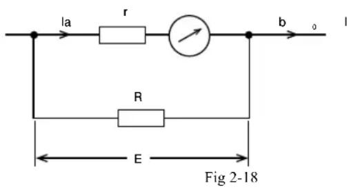
I : Voltmeter before multiplying [A]
I_0 : Voltmeter after multiplying [A]
R: Resistance of the electric shunt [Ω]
r : Internal resistance of the meter [Ω]
(resistance of the coil)
E: Voltage for applying electric current [V]
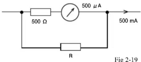
[Example 6] How much resistance is needed for R to obtain a 500mA-ammeter from a meter of 500 A-500Ω as shown in Fig 2-19?
(Answer) Substituting into (18) gives
$$ \mathrm{n} = \frac {\mathrm{I} _ {0}}{\mathrm{I}} = \frac {\times 1 0 5 ^ {3} 0 0}{\times 1 0 5 ^ {6} 0 0} = 1 0 0 0 $$
$$ \mathrm{R} = \frac {\mathrm{r}}{\mathrm{n} - 1} = \frac {5 0 0 \Omega}{1 0 0 0 - 1} \cong 0. 5 [ \Omega ] $$
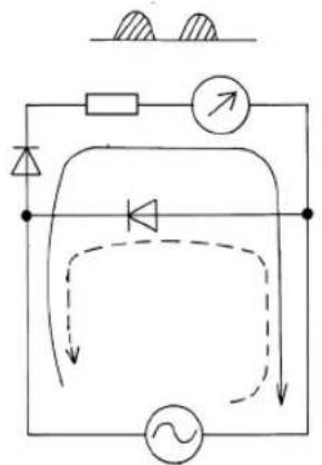
2-9 Rectification circuit
Testers have a structure that allows them to measure alternating current as well as direct current. Here is a simple explanation of rectification circuit that converts alternating current into direct current.
flowchart
graph TD
    A["Diode"] --> B["R"]
    B --> C["Resistor"]
    C --> D["Capacitor"]
    D --> E["AC Source"]
    E --> F["Ground"]
    style A fill:#f9f,stroke:#333
    style B fill:#ccf,stroke:#333
    style C fill:#cfc,stroke:#333
    style D fill:#fcc,stroke:#333
    style E fill:#cff,stroke:#333
    style F fill:#ffc,stroke:#333
(a) Half - wave rectification
Fig 2-20
flowchart
graph TD
    A["Power Source"] --> B["Resistor"]
    B --> C{Diode}
    C --> D["Measurement Point"]
    D --> E["Ground"]
    C --> F["Inductor"]
    F --> G["Capacitor"]
    G --> H["Return Line"]
    H --> I["Switch"]
    I --> J["Ground"]
(b) Full - wave rectification
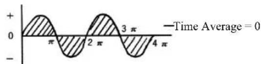
There are broadly two kinds of rectification circuits as illustrated in Fig 2-20. Generally, the half-wave rectification scheme shown in (a) is adopted in most testers. Since meters indicate the average value of the measured voltage, if the alternating current shown in Fig 2-21 (a) is applied to a meter, the meter will show almost no response at 20-30Hz or higher frequencies. By rectifying the current with a rectifier (a set of diodes), the current will be converted into the waves shown in Fig (b); the average value will be Iav and the meter will respond to the current. The value Iav is almost proportional to the input voltage and alternating currents can thus be measured.
line
| Time (π) | Value | | -------- | ----- | | 0 | 0 | | π/2 | 2π | | 3π/4 | 0 | | π | -2π |(a) [Alternating Current]
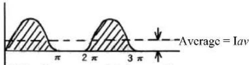
(b) [Half-wave rectified current]
Fig 2-21
It is generally convenient to express the alternating current by the root mean square (RMS) value rather than the average value. The RMS value is hence used as the scale of the tester. The following equations relate the maximum and RMS values of a sinusoidal alternating current :
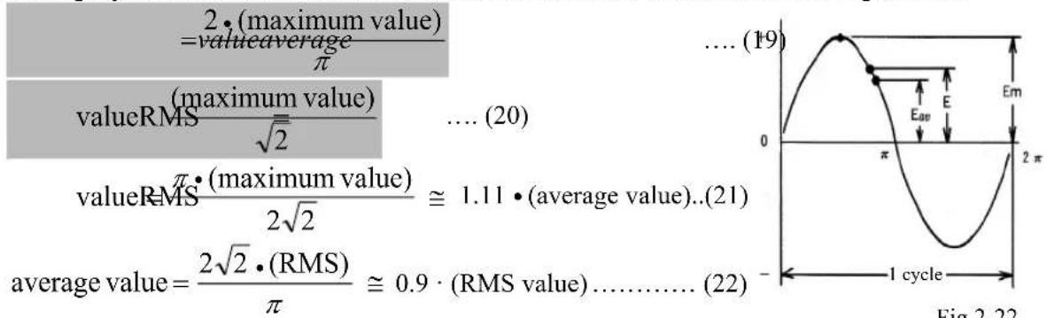
Iav, the direct current obtained by half-wave rectification of a sinusoidal alternating current I, is expressed as follows by transformation of (19) and (20):
$$ \mathrm{Iav} = \frac {2 \times \left(\sqrt {2} \times \frac {1}{2} \mathrm{I}\right)}{\pi} = \frac {\sqrt {2}}{\pi} \mathrm{I} = 0. 4 5 \mathrm{I} $$
$$ (\mathrm{I} = \frac {1}{0 . 4 5} \mathrm{Iav} = 2. 2 2 \mathrm{Iav}) $$
2-10 Principle of an ohm meter
I_0 , the electric current that will flow through the circuit when the SW is turned on in the circuit designated in Fig 2-23, is
$$ \mathrm{I} _ {0} = \frac {\mathrm{E}}{\mathrm{R} _ {\mathrm{T}}} \dots \tag {23} $$
When the SW is turned off, R_x will be included in the circuit in serial and hence
$$ \mathrm{I} = \frac {\mathrm{E}}{\mathrm{R} _ {\mathrm{T}} + \mathrm{R} _ {\mathrm{X}}} \dots \tag {24} $$
The ohm meter of a tester uses the reduction of the electric current to calculate the value of R_X .
From (23) and (24), P, the ratio against I_0 , is
$$ = \frac {\mathrm{P} I}{I _ {0}} = \frac {\frac {E}{R _ {T} + R _ {X}}}{\frac {E}{R _ {T}}} = \frac {R _ {T}}{R _ {T} + R _ {X}} \dots (2 5) $$
From (25),
$$ R _ {X} = R _ {T} \bullet \left(\frac {1}{P} - 1\right) \tag {26} $$
When P, the ratio of _0 , is assumed to be 1/2, (26) becomes
$$ _ {X} = _ {T} \bullet \left(\frac {1}{1 / 2} - 1\right) R R R = \dots \tag {27} $$
This suggests that the 50% point (1/2) of the effective meter deflection angle is the internal resistance of the ohm meter. The scale of a tester can be calculated from (25).
[Example 7]
When the internal resistance of a tester (R _T ) is 10.4kΩ, what percent does the point of 5kΩ correspond to of the effective meter deflection angle?
(Answer) From (25),
$$ \mathrm{P} = \frac {\mathrm{R} _ {\mathrm{T}}}{\mathrm{R} _ {\mathrm{T}} + \mathrm{R} _ {\mathrm{X}}} \times 1 0 0 = \frac {1 0 . 4 \mathrm{k} \Omega}{1 0 . 4 \mathrm{k} \Omega + 5 \mathrm{k} \Omega} \times 1 0 0 \cong 6 7. 5 (\%) $$
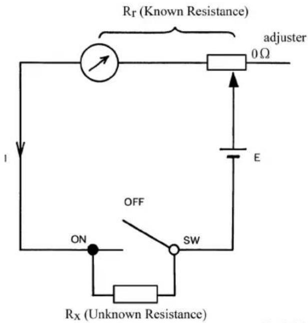
Fig 2-23
2-11 Color code and rating code
There are certain agreements on the method of indication for resistors and capacitors. Color code and rating code are described in this section. Color code is mainly used for resistors, while rating code is used for capacitors.
① Example of indication of a precision resistor
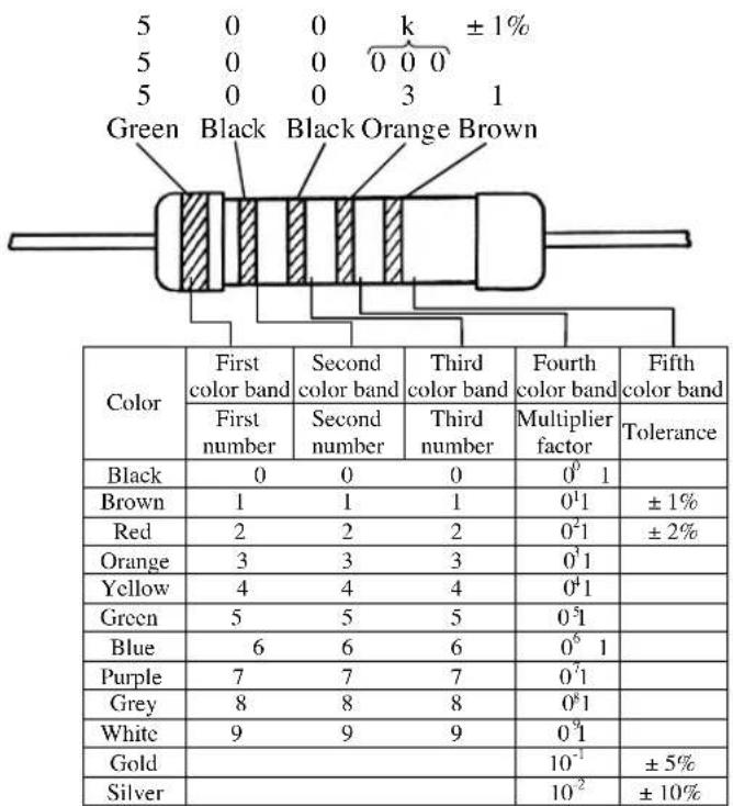
Fig 2-24
② Example indication of a general resistor (for household use)
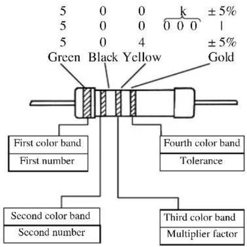
Fig 2-25
Tolerance code
| B:±0.1% | C:±0.25% | D:±0.5% | F:±1% |
| G:±2% | J:±5% | K:±10% | M:±20% |
③ Example of indication of capacitors
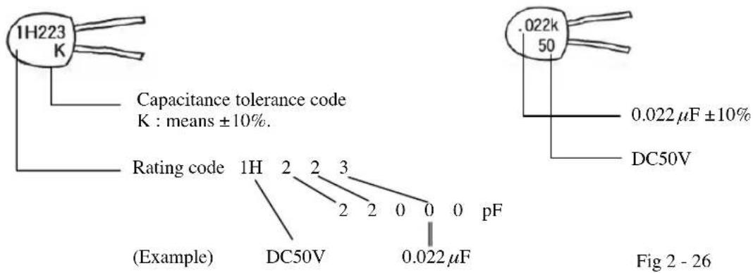
Rated voltage code
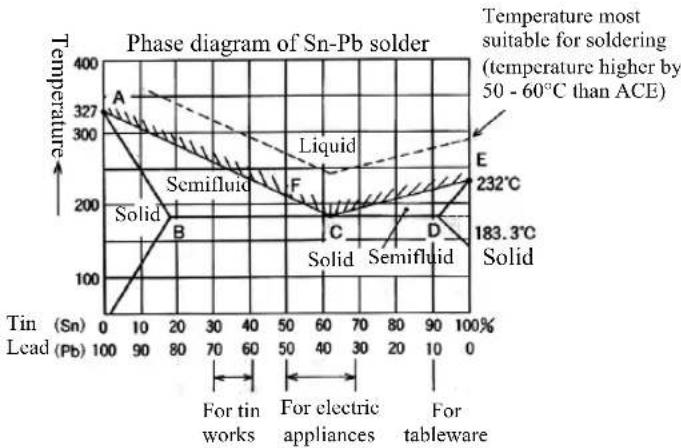
3-1 Properties of soldering
As seen in the tin-lead phase diagram, the conditions around point C are beneficial for soldering of electronic components that are easily affected by heat. Point C is called the eutectic point and the solder of 62-63% tin, 37-38% lead is called the eutectic solder.
A solder of 60% / 40% is used for general electric appliances. Since this set of conditions has a range of semifluid phase (215°C - 183.3°C = 31.7°C), it takes some time for the solder to set.
This is the reason why you should never move the material immediately after soldering. Other solders include solders for tins, low-lead solder for food use in view of hygiene, etc.
line
| Phase | Temperature (°C) | |-------|------------------| | A | 327 | | B | 200 | | C | 183.3 | | D | 183.3 | | E | 232 |Fig 3-1
Point A .... Melting temperature of lead : 327.4°C
Point E .... Melting temperature of tin : 231.9°C
Point C .... 61.9% tin - 38.1% lead
Melting temperature : 183.3°C
Point F .... 50% / 50% tin / lead
Melting temperature : 215°C
3-2 Soldering Method
① Preparation
(a) Clean the tip of the soldering iron. Judge if the temperature of the tip is suitable for soldering. How to judge: the temperature is too high if the tip repels solder; the temperature is too low if solder melts slow and gives a matt finish. Change the length of the tip for temperature adjustment.
(b) Remove grease, dirt or rust from the part to be soldered.
(c) Apply solder beforehand separately to both of the parts to be soldered together (pre-soldering) if soldering or mounting of the components is difficult.
② How to use resin flux cored solder
The ordinary way to apply resin flux cored solder is as follows: Hold the solder iron in your dominant hand and solder in the other hand. Follow the procedures shown in the illustrations 1 to 6 in Fig 3-2: Preheat the part to be soldered with the solder iron, deliver the solder to the boundary of the solder iron and the part preheated. Sweat the solder at a needed amount and then detach the solder. Carefully look at the flow of the molten solder when you detach the solder iron. The crucial point is when to detach the solder iron.
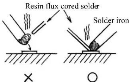
Fig 3-1
[Procedures]
![Sanwa KIT-8D - [Procedures] - 1](/content/2026/05/1043524/images/0894b7cbf2974ad06f89d28dbd88e497e740fdc9f028f71900f9d59b471558be.jpg)
Apply the
solder iron to
the material.
![Sanwa KIT-8D - [Procedures] - 2](/content/2026/05/1043524/images/7d329972e9823d14a58771fe502b2e8ff8d0ee0a421c33812bffb04e758e0e18.jpg)
Put the solder
onto the
boundary.
![Sanwa KIT-8D - [Procedures] - 3](/content/2026/05/1043524/images/3795c70c8dddb9dfbe6af2c40d36fe398ba8804ba2ed6f53f86f8f86660318f8.jpg)
Sweat the solder by 3-4 mm.
![Sanwa KIT-8D - [Procedures] - 4](/content/2026/05/1043524/images/f4227e39b78ebcd763b5b5ca1a4c42049348c7b9791153acfb1fd4a5d3701ab0.jpg)
Detach the
solder.
![Sanwa KIT-8D - [Procedures] - 5](/content/2026/05/1043524/images/dd23ad2d87e898bd25b1e6812959684f7105510cafe7ba50e1b250f01faab2e2.jpg)
Detach the solder iron.
![Sanwa KIT-8D - [Procedures] - 6](/content/2026/05/1043524/images/60a156e9a2bf19e77359131d329a5563808fdde22b967b017008a347ebf3cd6e.jpg)
Leave the material to cool.
Fig 3-2
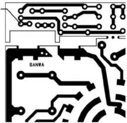
3-3 Soldering practice
KIT -8D has a small board for soldering exercise. Deliver the solder into the part for soldering on this board to practice soldering. Cut the part off after training.
Do not use this part for practice if you use the optional buzzer kit. (Use the part without holes for practice, the part at the right hand side when you place the circuit board in a direction shown in the figure.)
Patterns for soldering exercise
natural_image
Pure electrical circuit lines without any symbolsFig 3-3
3-4 Preparations for assembling
① Tools required
| Check | Name | Note |
| Soldering Iron | 20 - 30W | |
| Tweezers | Either of these (Small size) | |
| Radio Pliers | ||
| Nippers | (Small size) |
| Check | Name | Note |
| + Phillips Screwdriver | (Middle size) | |
| Hand file | For maintenance of the iron tip | |
| Scissors | Prepare as needed |
② Verification of the components
Take the components out of the package and collate them with the parts list.
| Check | Symbol | Item name | Quantity | Check | Symbol | Item name | Quantity |
| a | Set of resistors and diodes | 1 | l | Printed board | 1 | ||
| b | Battery terminal | 1 | m | Dial plate | 1 | ||
| c | Battery fittings | 2 | n | Name sticker | 1 | ||
| d | Switch brush | 1 | o | Panel (already mounted with the meter and the range selector knob) | 1 | ||
| e | Fuse fittings | 2 | p | Case | 1 | ||
| f | Mini fuses 0.5A/250V | 2 | q | Protection cover | 1 | ||
| g | Capacitor 0.022μF | 1 | r | AA size batteries (UM-3) | 2 | ||
| h | Zero Ω adjuster 10k Ω | 1 | s | Test leads (red & black) | One pair | ||
| i | Knob for zero Ω adjuster | 1 | t | Hand strap | 1 | ||
| j | Case stopper screw | 1 | Resistor for checking 100Ω | 1 | |||
| k | Solder | 1 | Resistor for checking 22kΩ | 1 |
3-5 Assembling and wiring
① Caution for assembly and wiring
Do not turn the switch knob before assembly. The ball and spring included inside may leap out.
a) Read the cautions well and perform assembly and wiring in the order given.
b) The panels are made of resin and may melt and deform when in direct touch with the solder iron.
c) Make sure of the position when you stick on the dial and name sticker.
d) Solder quickly so as not to overheat the printed board.
② Wiring and assembly of the printed board
②-1 How to wire and assemble
You can assemble this product in different ways as described below. You can choose one of the following ways as you desire :
A) Assemble in the order of the parts list
This method is beneficial if you want to assemble the product quickly.
B) Assemble by referring to the layout plan
This method is helpful in learning how to read the color code of the resistors.
C) Assemble in the order of the circuit structure
This method allows you to assemble while understanding the circuit of the tester.
A) Assemble in the order of the parts list
Set up the resistor mount sheet as described below. After setting up, go to the process 2-2.
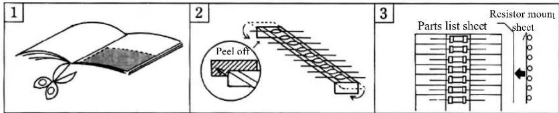
1 Cut out the parts list sheet printed in Page 61.
2 Fold the top and bottom of the sheet. Peel off the films of the double-faced tapes.
3 Stick the tapes to the parts list sheet so that the resistors come to the upper side and the diodes to the lower side. (Completion of the resistor mount sheet)
B) Assemble by referring to the layout plan
Take the resistor set and the printed board out of the parts bag. Start from the process ②-2. Install the components by referring to the component layout plan designated in Page 39.
C) Assemble in the order of the circuit structure
Refer to the assembly procedures described on Page 40 onwards.
②-2 Bending of the lead wires of the components
It is very convenient to bend the lead wires of the components using the small board when you mount the components to the printed board. Put the body of a resistor or a diode into the square hole of the small board as shown in Fig 3-5. Press the resistor or the diode with your thumb and bend the lead wires in the right angle by forcing the lead wires to the edge of the small board using the other hand. In this way the components can be processed to fit to the printed board. This processing can also be done using tweezers or radio pliers.
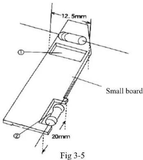
Note) Place the diode so that the body comes to the center of the square hole when you bend the wires of D1-D7 because the hole is too large for these diodes.
②-3 Soldering of the components
Insert the bent lead wires of the components into the printed board and solder them.
Repeat the bending and mounting processes for one component at a time: Bend the lead wires of a component and mount it, and then bend the wires of the next component, and so on.
※ Bend the lead wires a little to ease soldering.
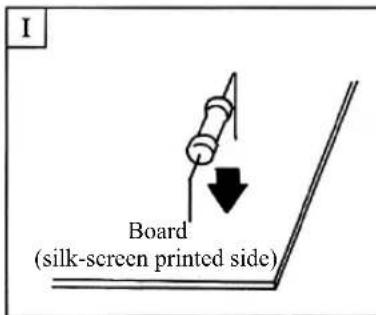
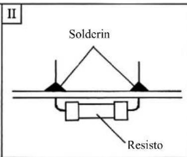
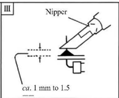
Fig 3-6
| Order | Check | No. | Operation |
| 1 | I | Insert the wires processed according to 2-2 into the predetermined position from the back side (silk-screen printed side) of the board. (See Fig 3 - 6) | |
| 2 | II | Mount the component by soldering the solder side (green side) of the printed board. Take care not to apply too much solder. | |
| 3 III | Cut the redundant lead wires off using nippers. Repeat the processes I - III until all the components are mounted. |
Note : Polarity of diode
Diodes have polarity. Mount them in the same direction as designated in the silk-screen print (white print) on the printed board.
Note • Take care not to overheat the board or apply too much solder when soldering.
- Do not move the components until the solder is set.
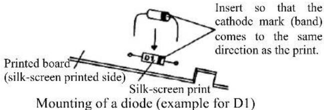
③ Mounting of capacitor
a) When assembling in the order of the parts list or the circuit structure
Insert the component into C1 of the printed board and mount it.
b) When assembling referring to the layout plan
Find the place of C1 in the layout plan on Page 39. Insert the component into the printed board and mount it.
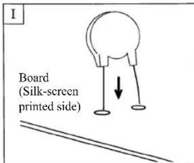
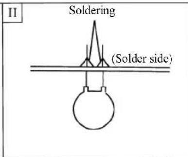
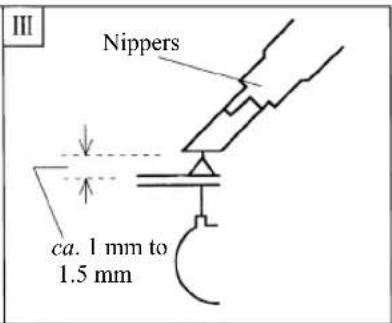
Fig 3-7
| Order | Check | No. | Operation |
| 4 | Insert the capacitor into the position from the silk-screen printed side of the board. | ||
| 5 | Solder the terminals of the capacitor from the solder side (green side) of the printed board. | ||
| 6 | Cut the redundant terminal wires off using nippers, leaving ca. 1-1.5 mm margin. |
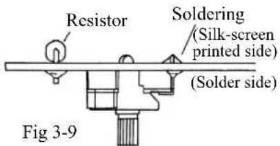
④ Installation of zero Ω adjuster
| Order | Check Operation | |
| 7 | Insert the zero adjuster from the solder side into the printed board and solder it. (See Fig 3-8)The appearance after installation is illustrated in Fig 3-9. (The adjuster is mounted on the other side of the resistors.) | |
Note • Mount the zero Ω adjuster so that it is not tilted. Check once before soldering if it is tilted. The adjuster will rub the hole of the panel and will not turn smoothly if it is tilted.
- Soldering can be performed easily when the zero adjuster is fixed on the circuit board with adhesive tape.
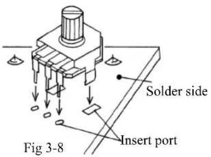
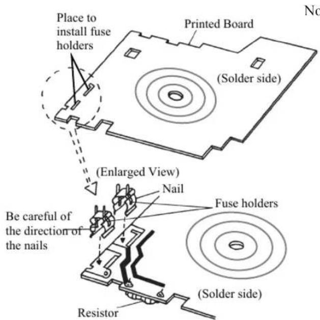
⑤ Installation of fuse holders
| Order | Check | Operation |
| 8 | Insert | the fuse holders from the solder side (green side) into the printed board and solder them. (See Fig 3-10) |
Note
- Be careful of the direction of the nails when inserting the fuse holders. - It is convenient to use the edge of the desk when soldering the fuse holders.
(See Fig 3-11)
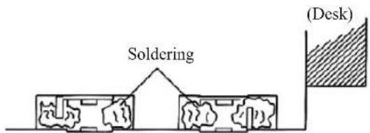
Fig 3-11
Fig 3-10
⑥ Installation of battery fittings
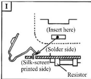
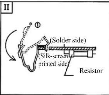
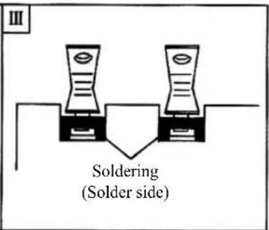
Fig 3-12
| Order | Check | No. | Operation |
| 9 | I | Insert the battery fittings from the solder side of the board. The place of mounting is on the upper-left side when seen from the solder side of the board. | |
| 10 | II | From the position 1 (illustrated in dotted lines), turn the fittings so that they are straight along the printed boards as shown in the figure. | |
| 11 | III | Solder firmly at the position shown in the figure. | |
Note • Make sure of the direction when you insert the battery terminal.
- In the case that the open part of the battery fitting is crushed, restore the shape to its original state by using your fingers. Connection between the battery and the fitting may fail if the fitting is left deformed.
⑦ Installation of fuse
| Order | Check | Operation |
| 12 | Mount a fuse on the fuse holders as shown in the figure. (One of the two fuses included in the package is the spare fuse and will be installed in the later process.) | |
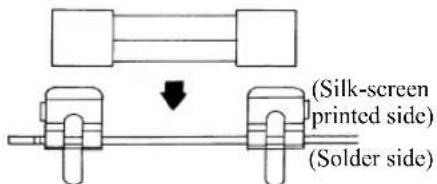
Fig 3-13
⑧ Installation of test leads
| Order | Check | Operation |
| 13 | Put the red test lead through the hole at the fuse holder side of the printed board; put the black test lead through the hole at the position shown in the figure.Bend the core wires down to the printed board side. Solder the wires. | |
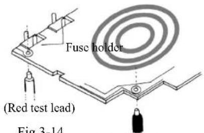
Fig 3-14
(Black test lead)
Note • Insert the test leads from the back side of the printed board (silk-screen printed side).
Assembly check (I) Assembly of the printed board
| Inspection Check | Corresponding Article | Items to be checked |
| 2 - 3 | Is there any mistake in mounting of the resistors and diodes ? (Position of installation, polarity of the diodes, etc.) | |
| 4 | Is the zero Ω adjuster inserted from the solder side (green side) ? | |
| Is the zero Ω adjuster installed without tilt? (See Fig 3-9) | ||
| 5 | Are the fuse holders inserted from the solder side (green side) ? | |
| Is the direction of the nails of the fuse holders correct ? (See Fig 3-10) | ||
| 6 | Are the battery fittings installed without tilt? (See Fig 3-12 II) | |
| Are the battery fittings not crushed ? (See 6 Note) | ||
| 7 | Have you not forgotten to install the fuse? | |
| 8 | Are the positions of installation of red and black test leads correct (not reversed)? | |
| Are the red and black test leads inserted from the silk-screen printed side of the printed board? | ||
| 2-3 ~ 6 and 8 | Is the soldering well done? Have you not forgotten to solder any component? |
If you find anything wrong through the inspection check, see the assembly procedures in the corresponding article and correct to solve the problem. Proceed to the next procedures only after inspection is finished. Progress in the same way for the rest of the processes and inspections.
⑨ Installation of switch brush
| Order | Check | Operation |
| 14 | Install the | switch brush onto the range selector knob mounted on the panel. |
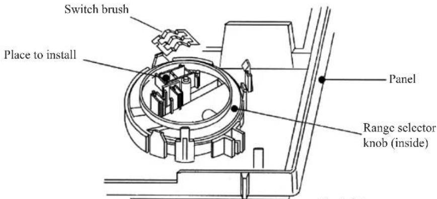
Fig 3-15
| 1 | Turn the range selector knob to align the positions of A and B as illustrated below. |
| 2 | Direct the switch brush so that the mark on it comes to the upper-left side. |
| 3 | Hook the switch brush first to the projections at the left hand side of the range selector knob. |
| 4 | Press the right hand side of the switch brush with your fingers to install. |
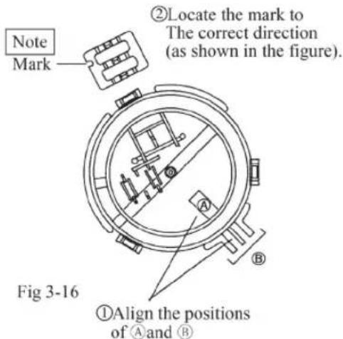
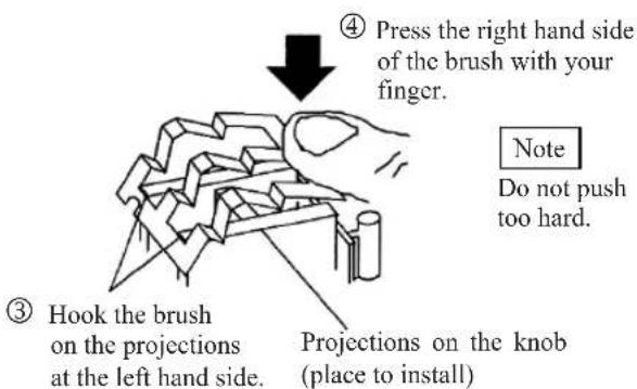
Fig 3-17
Note
Do not push the brush at the contact points from directly above when fitting the switch brush into place. It may cause deformation of the switch brush.
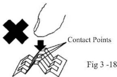
Assembly check (II) Installation of switch brush
| Inspection Check | Corresponding Article | Items to be checked | |
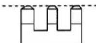
| 9 | Is the mark of the switch brush in the correct direction?(See Fig 3-16) | ||
| Do the contact points of the 9 | switch brush have the same height?(They should not be crushed). | This height shallbe uniform. | |
 | |||
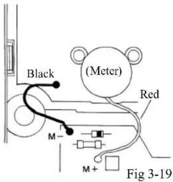
⑩ Soldering of meter leads
| Order | Check | Operation |
| 15 | Put | the red lead wire coming from the meter through the position of “M+”; put the black lead wire coming from the panel through the position of “M-”. Solder the wires. |
- Solder the core wires after bending the wires to the printed board side (solder side).
⑪ Installation of the completed printed board
| Order | Check | Operation |
| 16 | Install | the completed printed board onto the panel. Fasten the printed board by the three nails on the panel as shown in the assembly diagram. |
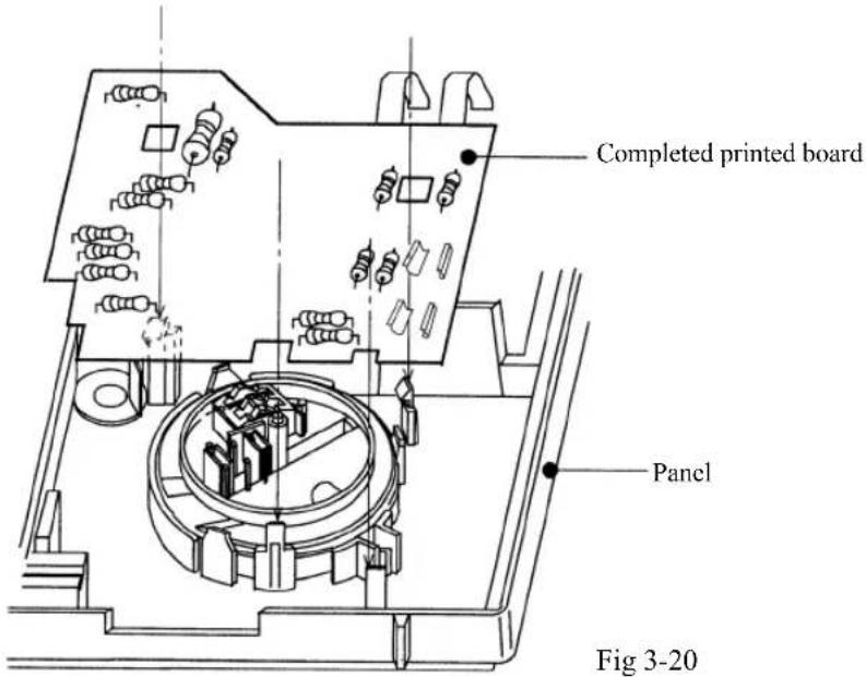
| 1 | Hold the panel in your hands as illustrated below. Position the completed printed board roughly and put it onto the panel lightly.Note) Hold the panel in your hands when you fasten the board. |
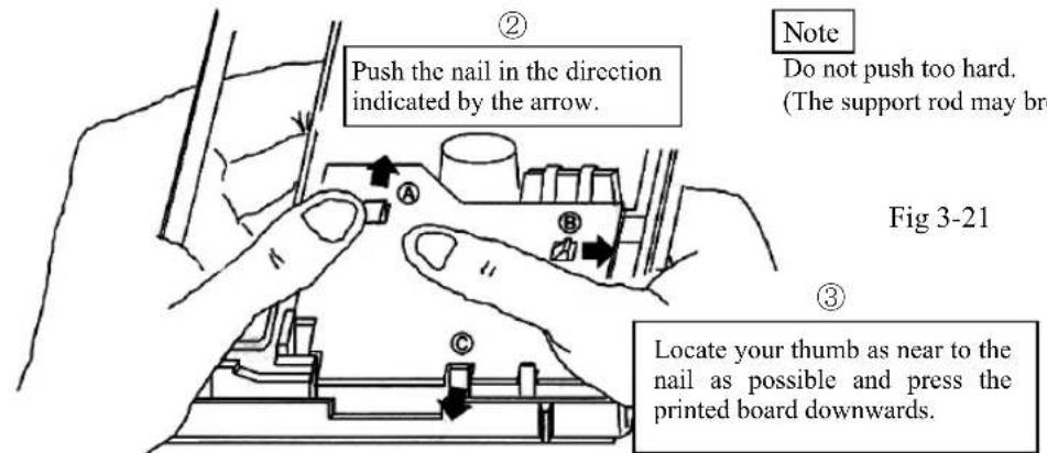
| 2 | Beginning from part Ⓐ of the figure below, push the nail with your thumb to the direction indicated by the arrow in the figure. |
| 3 | With the nail still pressed, push the printed board into position with the other hand. |
| 4 | Repeat the processes for part Ⓑ and part Ⓒ, one at a time; pushing the nail in the direction indicated in the figure, push the board into position in the same way as for part Ⓓ. |

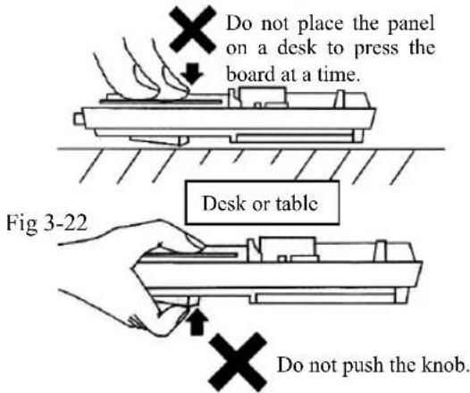
Do not try to fasten the printed board at a time by placing the panel on a desk, with the meter part facedown, as illustrated in Fig 3-22. Be careful not to press the range selector knob when you hold the panel within your hands to fasten the printed board; the knob may come off if pressed.
In the case that the knob has come off, reinstall the knob following the installation method for the range selector knob described in Page 39.
⑫ Arrangement of test leads
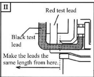
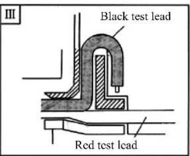
Fig 3-23
| Order | Check | No. | Operation |
| 17 | I | Straighten the red test lead to the left hand side. Push the red lead into the ditch of the panel shown as the shaded portion in the figure. | |
| 18 | Adjust the length of the black lead so that the length from the outlet of the lead presser becomes the same as that of the red lead. Hold the outlet part temporarily. | ||
| 19 | Push the black lead firmly into the ditch shown as the shaded portion in the figure. |
Note • Adjust the length of the test leads so that the length from the outlet of the lead presser becomes the same for both red and black leads.
- Lightly pull the leads after arrangement of the leads to check if they do not come out.
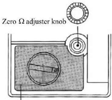
⑬ Installation of dial plate and zero Ω adjuster knob
| Order | Check | Operation |
| 20 | Peel | the back side sheet off from the dial plate and stick the dial plate onto the panel in the position shown in the figure. |
| 21 | Put the zero Ω adjuster knob along with the shaft of the zero Ω adjuster and snap into the position shown in the figure. |
Note • Stick the dial plate on slowly and calmly. If the dial is attached in the wrong position, pull it off slowly from the edge and try to stick it on again.
- Check if the zero adjuster is tilted when the knob cannot be fitted easily.
Position to stick the dial plate on
Fig 3-24
⑭ Mounting of batteries and battery terminal
| Order | Check | Operation |
| 22 | Install | the battery terminal in the position in the panel as shown in the figure. Place firmly and be careful of the direction, which edge is the top or the bottom (Fig 3-25). |
| 23 | Install | two AA size dry batteries. Be careful of the polarity of the batteries. (Fig 3-26). |
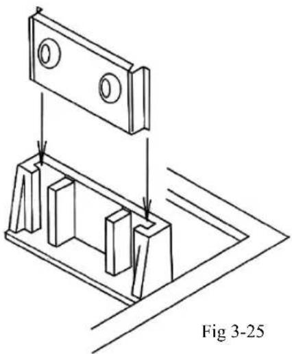
natural_image
Technical line drawing of a mechanical assembly with mounting brackets and a bracket, labeled Fig 3-25 (no text or symbols on the diagram itself)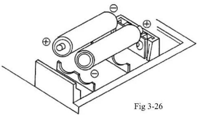
natural_image
Technical line drawing of a battery pack assembly with no visible text or symbols⑮ Mounting of spare fuse
| Order | Check | Operation |
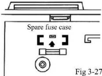
| 24 | Insert | the spare fuse into the spare fuse case on the panel. |
Assembly check (III) Assembly of the panel
| Inspection Check | Corresponding Article | Items to be checked |
| 10ad wires of the | Are the red and black meter lead wires connected to M+ and M-, respectively? | |
| Do the lead wires of the meter not come out when pulled lightly? | ||
| test lead not pin | Is the printed board fastened tightly by the three nails of the panel? | |
| Is the pinched between the panel and the printed board? | ||
| 12 | Are the test leads fitted firmly into the position of installation of the panel? | |
| 13 | Is the dial plate not stuck too far from the position to be placed? | |
| Have you not forgotten to install the zero Ω adjuster knob? | ||
| Does the zero Ω adjuster knob turn smoothly? | ||
| 14 | Have you not forgotten to install the batteries or the battery terminal? | |
| Is the polarity of the batteries correct? | ||
| 15 | Have you not forgotten to mount the spare fuse? | |
⑯ Installation of hand strap and rear case
| Order | Check | Operation |
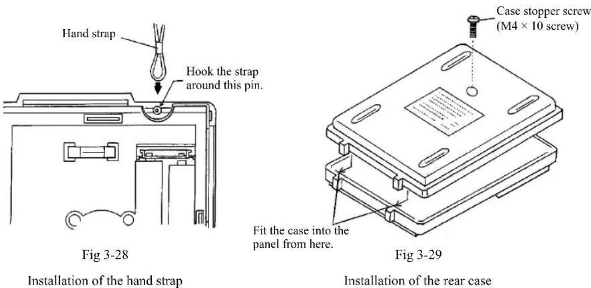
| 25 | Attach the | hand strap to the panel as illustrated in the figure. (Fig 3-28) |
| 26 | Fit the | rear case into the panel from the bottom. Align it with the panel and insert the case stopper screw into the place shown in the figure. Screw it with a Phillips screwdriver. (Fig 3-29) |
⑰ Attachment of name sticker
| Order | Check | Operation |
| 27 | Attach | the name sticker on the rear case in the position designated in the figure and write your name on it. |
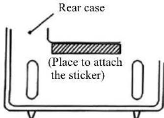
Fig 3-30
⑱ Storage of the test leads
| Order | Check | Operation |
| 28 | Put the | test leads into the storage space at the main body. Put the test pin side in first when storing. |
Note • The test leads are tied up. Loosen the bundle when storing.
natural_image
Line drawing of a vintage analog voltmeter with a dial, eraser, and pencil holder (no text or symbols)Fig 3-31
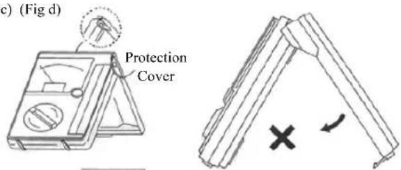
⑲ Installation of protection cover
| Order | Check | Operation |
| 29 | As illustrated in Fig 3-32, insert the installation pin inside the cover into the ditch and slide it to the direction designated by the Arrow 1. After sliding, close the cover in the direction designated by the Arrow 2. Do not press the cover down from above as shown in Fig 3-33; this may break the cover. | |
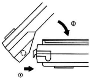
Fig 3-32
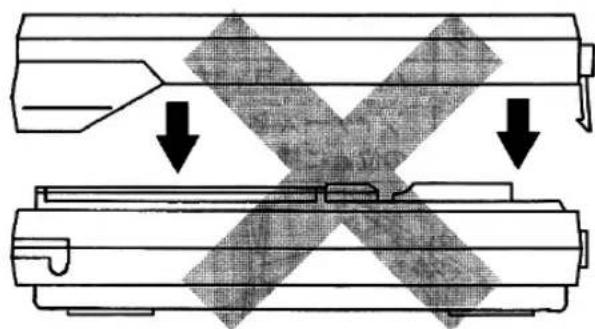
natural_image
Diagram showing two mechanical components with cross-shaped cutouts and downward arrows indicating motion or force (no text or symbols)Fig 3-33
Assembly check (IV) Finish
| Inspection Check | Corresponding Article | Items to be checked |
| 16In body fastened | Have you not forgotten to attach the hand strap? | |
| Is the main body fastened | d firmly with the case stopper screw? | |
| 17 | Have you not forgotten to attach the name sticker? (Fill in your name) | |
| 18 | Are the test leads stored in place? | |
| 19 | Is the body cover installed correctly? | |
Now assembly is completed.
Component layout plan
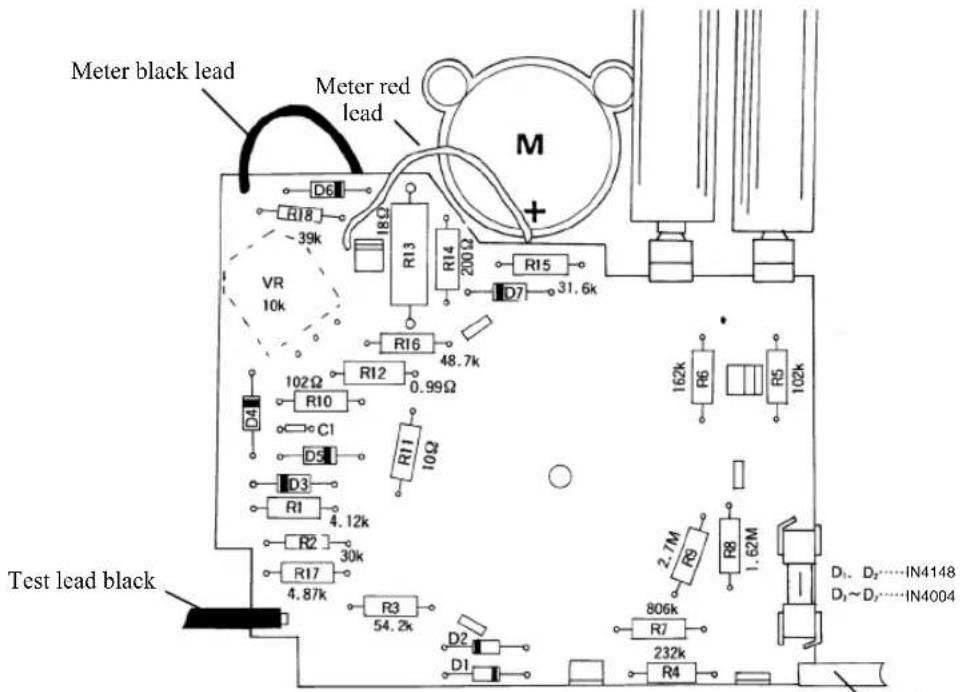
Fig 3-34
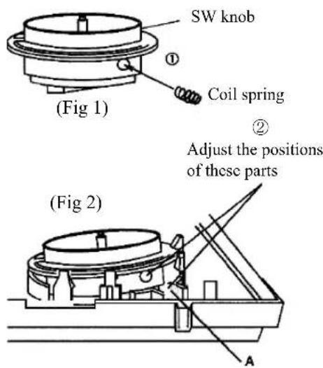
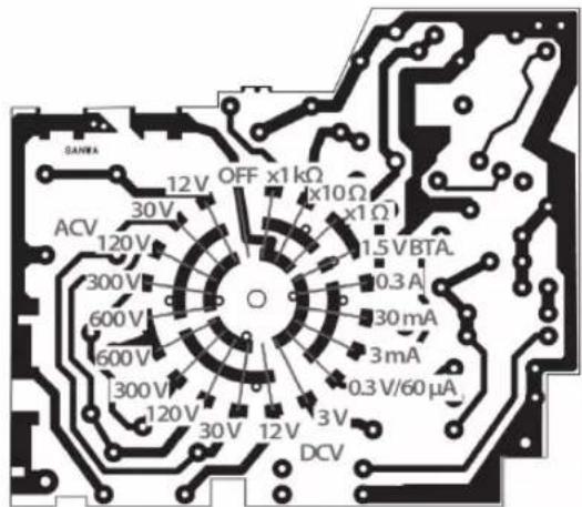
● Installation of the range selector knob
For KIT-8D, the range selector knob is already incorporated into the panel.
In the case that the range selector knob has come off during assembly procedures, follow the procedures below to reassemble:
- Procedure for installation -
① Insert the coil spring into the hole at the side of the range selector knob. (Fig 1)
② Place the range selector knob lightly onto the place of installation of the panel. Adjust the position of the range selector knob so that the hole to which the spring has been inserted and part A shown in the figure come together. (Fig 2)
③ Place the still ball on part A. (Fig 3)
④ Press the knob from the above. (Fig 3)
C) Assemble in the order of the circuit structure
Assembly procedures
1) Perform the processes 4 to ⑨, ⑬, installation of the dial plate, and installation of the battery terminal in process ⑭.
2) After completion of the above processes, mount the components by referring to the processing procedures described in processes 2-2 and 2-3.
3) Always displace the soldering of the meter lead out of the printed board and dismount the printed board from the panel when you proceed to the next circuit structure. (See How to displace the printed board, Page 42)
Note) ◆ You may attach the circuit components onto the parts list sheet; you may otherwise refer to the component layout plan illustrated on Page 39.
Do not force open the printed board. Unlock the nails of the panel one by one when you displace the board.
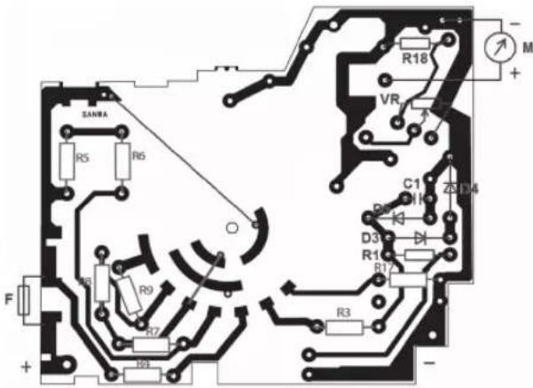
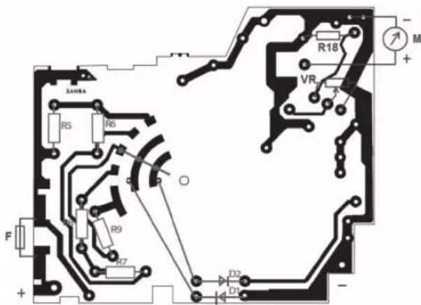
The figures below and the layout plan of the printed board show the pattern side (green side) of the printed board. Insert the components from the silk-screen printed side of the printed board and solder from the green side when you mount the components.
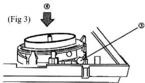
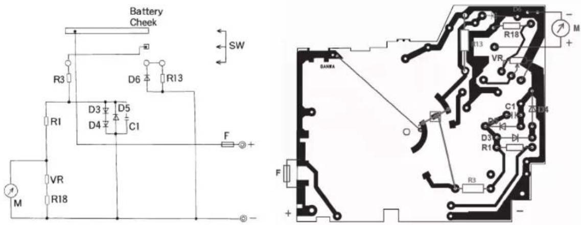
☐ Meter Circuit Mount the meter protection circuit, D3 - D5 and C1, resistors R1, R2 and R18. Wire the meter leads.
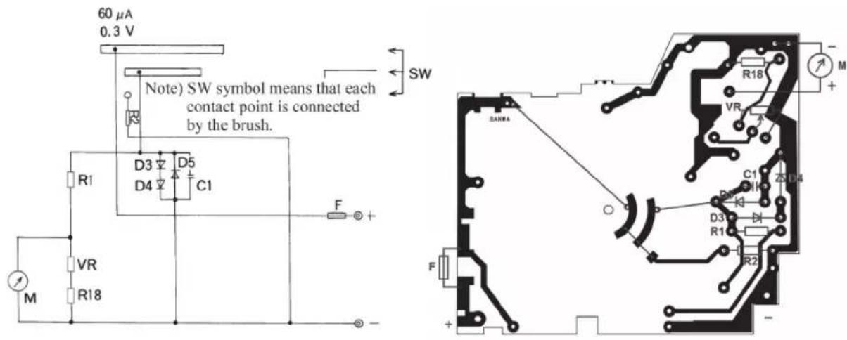
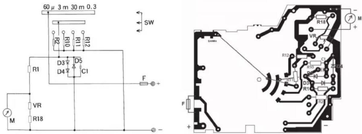
☐ Direct Current Ammeter Install the shunt resistors R10 (3mA), R11 (30mA) and R12 (0.3A).
□ Direct Current Voltmeter
Mount R3 (3V), R4 (12V) and R17. Install R5 to R9, which are common with the multiplier of the alternating current voltmeter.
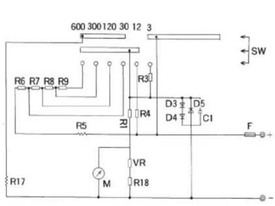
□ Alternating Current Voltmeter
The multiplier components, common with the direct current voltmeter, have already been mounted. Install rectifier diodes D1 and D2.
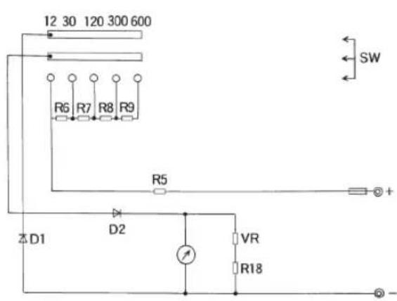
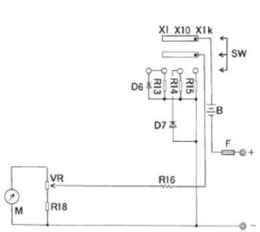
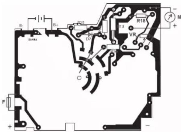
□ Ohm Meter
Install the serial resistor R16 and the shunt resistors R13 ( × 1), R14 ( × 10) and R15 ( × 1k). Mount the diodes for circuit protection, D6 and D7.
☐ Battery Check The battery check circuit is the one th at R3 and R13 is added to the meter circuit. No wiring is needed since these are already mounted.
☐ Switch Brush Position When viewed from the soldered surface. (patterned surface)
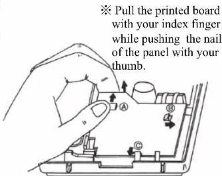
● How to displace the printed board
① First, dismount the zero adjuster knob before displacing the printed board.
② As shown in the right figure, pull the printed board lightly using your index finger while pressing the nail on the panel of the part ① in the direction designated by the arrow using your thumb until you hear a click that indicates the board has come off.
③ Undo nails Ⓑ, and then Ⓒ, one by one, in the same way as Ⓓ.
④ Remove the meter leads, red and black.
Note
- Do not push the nail too hard with your thumb. The support rod (nail) may break.
- Be careful when you pull the printed board with your index finger. The meter lead wires or other wiring may be disconnected if you pull off the board too hard.
- The pattern on the printed board may be disconnected if you force to displace the printed board without dismounting the zero adjuster knob.
IV Operation test and calibration
4-1 Quick operation check
- The circuit of this product does not require adjustment. Assembly and wiring of the product will simply provide the tolerance range described in the specifications. The product is thus ready to be used as a normal circuit tester after simple operation check.
- Operation check requires resistors (100Ω and 22kΩ), commercial power supply (100V), and a dry battery (take the battery out of this meter if you do not have one). (The resistors for checking are included in the parts bag.)
- Check the meter by following the procedures described below. Fill in the measured value or a check mark “√” in the blank square □ provided in the following descriptions :
① Preparation of measurement
- Meter zero adjustment
Turn the meter zero adjuster using a screw driver so that the needle indicator of the meter comes to the point of zero correctly when electricity is not applied to the circuit meter.
② Check of the DCmA range (the value of resistance in the parentheses in the equation below is the internal resistance of each range.)
(a) DC60 A range: Check the meter reading using a dry battery and a 22k -resistor for checking. (ca. 59 A)
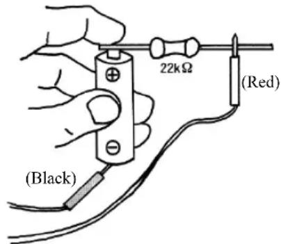
Fig 4 -1
※ Measurement will be facilitated by making a circuit illustrated in Fig 4 - 1 using a battery compartment, discrete circuit board, etc.
$$ \mathrm{I} = \frac {\mathrm{V} 6 . 1 . \mathrm{ca}}{\Omega + \quad \Omega) \mathrm{k} 5 (\mathrm{k} 2 2} \cong 5 9 \mu \mathrm{A} $$
(b) DC3mA range: Check the meter reading using a dry battery and a 22k -resistor for checking. (ca. 0.07mA)
$$ \mathrm{I} = \frac {\mathrm{V} 6 . 1 . \mathrm{ca}}{+ \Omega \quad \Omega) 5 . 1 0 0 (\mathrm{k} 2 2} \cong \mathrm{mA} 0 7. 0 $$
(c) □ DC30mA range : Check the meter reading using a dry battery and a 100Ω-resistor for checking. (ca. 14.5mA)
$$ \mathrm{I} = \frac {\mathrm{V} 6 . 1 . \mathrm{ca}}{+ \Omega - 1 \Omega) 5 . 1 0 (5 \mathrm{mA}} $$
(d) □DC0.3A range : Check the meter reading using a dry battery and a 100Ω - resistor for checking. (ca. 15.8mA)
$$ \mathrm{I} = \frac {\mathrm{V} 6 . 1 . \mathrm{ca}}{+ \Omega 1 0 (\Omega) 5 . 1} (8 \mathrm{m} $$
③ Check of the DCV range (observed value; the value in the parentheses is the voltage of the battery included in this kit)
(e) □ DC 3V range : Measure the battery voltage and read the meter. (ca. 1.6V)
(f) DC 12V range : Measure the battery voltage and read the meter. (ca. 1.6V)
(g) DC 30V range : Measure the battery voltage and read the meter. (ca. 1.6V)
(h) DC 120V range : Measure the battery voltage and read the meter. (ca. 1.6V)
(i) DC 300V range: Measure the battery voltage and read the meter.
(the needle twitches a little to the right)
④ Check of the alternating current voltage
⚠ Warning
- Always use a commercial power supply (101±6V) to which a circuit breaker is incorporated.
- Do not hold the test leads over the brim at the test pin end when measuring.
(j) AC120V range : Measure the commercial power supply and read the meter. (ca. 100V)
(k) AC300V range : Measure the commercial power supply and read the meter. (ca. 100V)
(1) AC600V range : Measure the commercial power supply and read the meter. (ca. 100V)
(m)☐ AC30V range : Measure the1 battery voltage and read the meter. (ca. 3.2V)
(Note) The meter reading will be zero when the polarity is reversed.
(n) □ AC12V range : Measure the battery voltage and read the meter. (ca. 3.2V)
(Note) The meter reading will be zero when the polarity is reversed.
⑤ Battery check range (check of 1.5V)
(o) □ 1.5V range : Measure the battery voltage and read the meter. (ca. 1.5V)
⑥ Check of resistance range (Restore the dry battery that has been used in check of DC voltage and current to the tester.)
(Note) Perform zero adjustment for each range.
(p) × 1k range: Measure the 22k - resistor for checking and read the meter. (22kΩ)
(q) × 10 range: Measure the 100 - resistor for checking and read the meter. (100Ω)
(r) × 1 range : Measure the 100 - resistor for checking and read the meter. (100Ω)
The checking procedures described above will provide the way to judge whether any of the range is in good condition or not. Check of the DC600V range can be omitted by performing AC600V range check and hence not described above.
(Note) In the check items (m) and (n), DC voltage is measured using ACV range; note that this procedure is not a measurement but is carried out for the purpose of checking the meter indication.
4-2 Calibration of the tester
Calibration is carried out to see if the assembled tester satisfies the accuracy as in the specifications. If the tester passes this examination, a highly reliable measurement is promised when you use it. In the case that the tester does not show the performance described in the specifications, there is a need to check if the correct resistances are mounted at the specified positions. Modification may also be needed including replacement.
① How to calibrate
The ordinary way to calibrate a measuring instrument is to adjust the indication of the instrument to be examined to the calibration scale and read the value of the standard device; calibration of testers also adopts this strategy. When calibration results are expressed in relative errors (see Page 43), M corresponds to the indication of the tester while T corresponds to the reading of the standard device.
Though JIS-C-1102 prescribes how to adjust the indication, description is omitted here because the tolerance of testers is large. The following illustrations show how to connect the devices:
(a) DC and AC Voltmeters
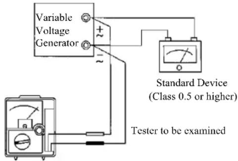
(b) DC Ammeter
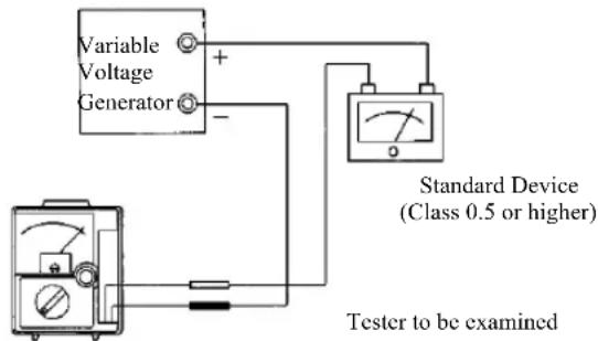
(c) Ohm Meter
Tester to be examined
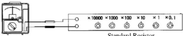
② Tolerance of a tester
Note that the tolerance of a tester is expressed as a value against the maximum scale value, not against the scale reading. For example, since the tolerance of the DC120V range of this product is within ±3% of the maximum scale value,
120V (maximum scale value) × ± 3% = ± 3.6V
Therefore, the tolerance range is ± 3.6V.
This value of tolerance range will apply to each of the points of graduation.
The tolerance of the resistance range, ±3% of the scale length, can easily be understood if converted to the V.A scale ( ±1.8 graduation of the V.A scale). The point of 50% (V.A scale) is usually used in checking an ohm meter.
③ Errors
An “error” is prescribed in JIS-C-1002 as “the difference between the measured value, setting value or rated value and the true value of the quantity measured or supplied. (The magnitude of an error is expressed in absolute error, relative error or percentage error.)” A measuring instrument has an error due to the instrument itself (error : ), such as of accuracy of the components; the relationship between the measured value M and the true value T is expressed as follows :
Absolute error = M - T
_0 , the relative error that indicates how large the absolute error is compared to the true value, is
$$ \text { Relative error } \varepsilon_ {0} = \frac {\varepsilon}{\mathrm{T}} \times 1 0 0 = \frac {\mathrm{M} - \mathrm{T}}{\mathrm{T}} \times (\%) 1 0 0 $$
For example, when the scale reading was 105V and the true value is assumed to be just 100V in measurement of the 100V - alternating current at the AC 300V range, the error is
$$ \text { Relative error } \varepsilon_ {0} = \frac {- 1 0 0 1 0 5}{1 0 0} \times = \% 5 1 0 0 $$
④ Items to be calibrated
In the calibration of a tester, the maximum scale value of each voltage or current range and the central scale value of each resistance range (20 , 200 and 20k for this product) are the calibration points. Other than this, a graduation characteristic test may be carried out to examine if the meter indicates in accordance with the scale graduation. Ten points, from 10% to 100% in steps of 10%, of the lowest current range (60 A for this product) are usually subjected to this test. This is to examine the dispersion of graduation profile (linearity) of the meter. Data for AC12V scale may be collected as a graduation characteristic considering the effect of the rectifier.
4-3 Measurement results
① Calibration of voltage and current (maximum scale value)
Date of examination : Conditions °C %
| Range | Reading of the tester (M) | Reading of the standard device (T) | Absolute error ε = M-T | Relative error ε0 = M-T/T × 100(%) |
| DC 600V | ||||
| 300V | ||||
| 120V | ||||
| 30V | ||||
| 12V | ||||
| 3V | ||||
| 0.3V | ||||
| DC 0.3A | ||||
| 30mA | ||||
| 3mA | ||||
| (60μA) | ||||
| AC 600V | ||||
| 300V | ||||
| 120V | ||||
| 30V | ||||
| 12V |
② Calibration of the ohm meter (indication)
| Range | Reading of the tester (M) | M' = _TR_T + M × 100% | Reading of the standard device (T) | T' = _TR_T + T × 100% | Relative Error _0 = T' - M' (%) |
| × 1k | 20kΩ | 50% | |||
| × 10 | 200Ω | 50% | |||
| × 1 | 20 | Ω 50% |
(Note) _ : the central scale value of the resistance range (internal resistance)
③ Calibration of the meter graduation characteristics (indication of DC60μA range)
| Reading of the tester (M) | M' = M60 A × 100(%) | Reading of the standard device (T) | T' = _100 × 100% | Relative Error _0 = M^ - T^ ( % ) |
| DC 60μA | 100% | |||
| 54μA | 90% | |||
| 48μA | 80% | |||
| 42μA | 70% | |||
| 36μA | 60% | |||
| 30μA | 50% | |||
| 24μA | 40% | |||
| 18μA | 30% | |||
| 12μA | 20% | |||
| 6μA | 10% |
(Note) T_(100) : reading of the standard device at the point of 100% (T)
4-4 Summary of the results
Plot the measurement results of 4-3 in a graph by defining as an over deflection and as an under deflection against the value of the standard device.
(Note) Use the scale of ( ) % for the plot of graduation characteristic because it gives small errors.
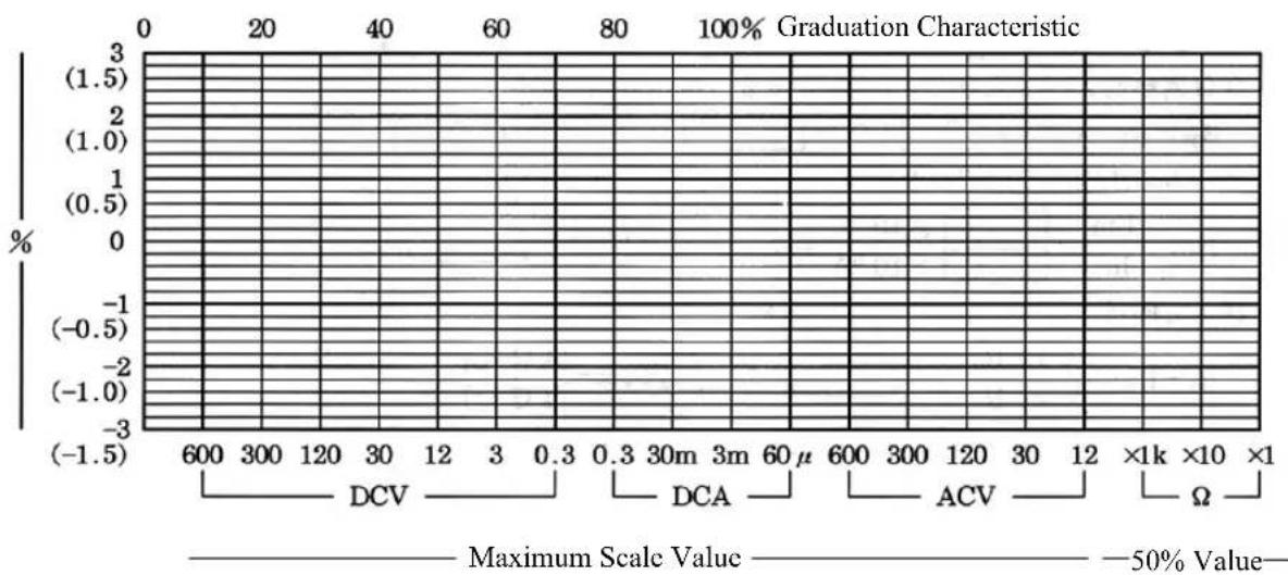
V Circuit calculation of the tester
5-1 Meter Circuit
The meter used in the tester is a moving-coil type as described earlier.
This moving coil is formed by rounding a copper wire of 0.02 - 0.04 mm thickness hundreds of times and it is therefore difficult to make a coil have a constant resistance value (internal resistance).
Since copper wire has a temperature coefficient of ca. +0.4% against an increase in temperature of 1°C, compensation of this change by the circuit is needed. Some high-class testers use a thermistor (which has a temperature characteristic opposite to that of copper wire) to compensate the temperature change. This product is designed to realise a non-adjusting system; a resistor is incorporated to the meter coil circuit in serial connection so that the ratio of the change becomes very small compared to the whole circuit.
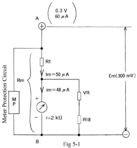
Im = Meter circuit current ; Rm = Meter circuit resistance ; im = Meter current sensitivity ; Em = Voltage between terminals
Meter circuit specifications : meter current sensitivity (im) ·s·s48 A±1%
meter internal resistance (r) ·s·s2k ±8%
working current of DC voltage & current (Im)· 50 μA
voltage between A and B (Em) 300mV (0.3V)
In the meter circuit shown in Fig 5-1, VR + R_18 will act as a shunt that magnifies im into Im.
Therefore, when this resistance is defined as R_0 , the equation (18) in Page 22 becomes
$$ n = \frac {I _ {0}}{I} $$
Where n = magnification factor
I = current before magnification = im
I_0 = current after magnification = Im
$$ \mathrm{n} = \frac {\mathrm{I} _ {0}}{\mathrm{I}} = \frac {\mathrm{Im}}{\mathrm{im}} = \frac {\boxed { * * } \mu \mathrm{A}}{\boxed { * * } \mu \mathrm{A}} \cong \square . \square \square \square \square R _ {0} ^ { * } k \frac {r}{n - 1} = \frac {\boxed { * * } k \Omega}{\boxed { * * } 1} $$
(round to the nearest integer : round up if the first digit of the fractional part is 5 or larger ; round down otherwise.)
When the zero Ω adjuster VR is 10kΩ (see 5-5 Ohm meter (Ω) circuit),
$$ \mathrm{R} _ {1 8} = \mathrm{R} _ {0} - \mathrm{VR} = \boxed { * * } \mathrm{k} \Omega - \boxed { * * } \mathrm{k} \Omega = \boxed { * * } \mathrm{k} \Omega $$
From Ohm's law, Rm is (from the specifications, Im = 50μA and Em = 300mV)
$$ \mathrm{Rm} = \frac {\mathrm{Em}}{\mathrm{Im}} = \frac {\boxed { * 1 0 ^ {- 3} \mathrm{V}}}{\boxed { * 1 0 ^ {- 6} \mathrm{A}}} = \boxed {} \times \quad^ {3} \Omega^ {*} * [ 0 ] k 2 $$
R_1 is hence
$$ R _ {1} = R m - \left(\frac {r \times R _ {0}}{r + R _ {0}}\right) = \boxed { * * } k \Omega - \left(\frac {\square k \Omega \times \boxed { * * } * * \Omega}{\square k \Omega + \boxed { * * } * * \Omega}\right) $$
$$ \cong \boxed {} k \Omega - \boxed { * * * } k \Omega = \boxed { * * * } k \Omega $$
5-2 DCA Circuit
The equation (18) for a shunt is used in calculation of DC ammeter circuit. Ohm's law also provides the way to calculate.
① DC60μA : from the equation (18) for a shunt,
n _0I _(60)Im A^* A^*
$$ R _ {2} ^ { * } \frac {R m}{n - 1} = \frac {\boxed { * * } k \Omega}{\boxed { * * } 1} = \boxed {} k \Omega $$
② DC3mA :
n 0I = (3)Im = * 10^-3 * 10^-6 = × ^3 = ***
$$ R _ {1 0} = \frac {R m}{n - 1} = \frac {\boxed { * * } k \Omega}{\boxed { } * * 1} = \frac {\boxed { * * } k \Omega}{\boxed { * * }} \cong \boxed {*} 2 * $$
I_0 = Measured Current Rm = Meter Circuit Resistance
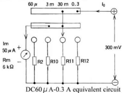
Fig 5-2
※ For questions ② to④, calculate to four decimal places and round off (half - adjust) to convert into the unit in the answer column.
③ DC30mA :
n _0I=_(30)Im=×10^-3×10^-6= R_11=-1=k**1
④ DC0.3A :
n _0I=_(0.3)Im=×10^-3×10^-6=* R_12^'= -1=l=*
The actual circuit has a resistance of ca. 0.01Ω due to contact resistance of the switch or the pattern of the printed board. This should be subtracted from the calculated value. (The resistance is negligible for other ranges because the value of the shunt is large.) Then,
$$ R _ {1 2} = R _ {1 2} ^ {\prime} - 0. 0 1 \Omega = * * * * * \Omega - 0. 0 1 \Omega = * * * * * \Omega $$
5-3 DCV Circuit
The equations for a multiplier are generally used in calculation of DC voltmeter circuit. You can otherwise use the value of /V , indicated on the tester, to calculate the resistance of a multiplier. Here, we will calculate using the equations for a multiplier.
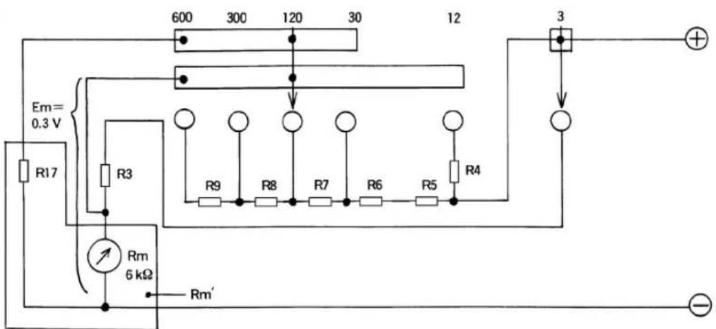
Fig 5-3 Equivalent circuit of DC3 V - 600 V
① DC3V
$$ \begin{array}{l} \mathrm{n} \quad \frac {\mathrm{E} _ {0}}{\mathrm{E}} \quad \frac {\mathrm{E} _ {(3)}}{\mathrm{Em}} \quad \frac { * * }{ * * * } = \boxed { * * } \quad_ {3} = \quad \bullet (k n R m) R = \square \Omega \times (\square - 1) ^ { * * * * * } 1 \ = \boxed { * * } k \Omega \times \boxed { * * } \ = \boxed {*} \text { 标 } 2 \ \end{array} $$
② DC12V
$$ \begin{array}{l} n \quad \frac {E _ {0}}{E} \quad \frac {E _ {(1 2)}}{E m} \quad \frac {\boxed { * * }}{\boxed { * * }} = \boxed { * * } R _ {4} = R m \cdot (n - 1) = \boxed { * * } k \Omega \times (\boxed { * * } - 1) \ = \boxed { * * } \mathrm{k} \Omega \times \boxed { * * } \ = \boxed {*} k _ {2} \ \end{array} $$
③ DC30V
Because the same circuit as ACV is used for DC30V to DC600V, a shunt R_17 is incorporated in the meter circuit in make them have the same sensitivity with ACV (9k /V ). The current sensitivity of ACV9k /V is
$$ \mathrm{I} _ {(\mathrm{AC})} = \frac {1 \mathrm{V}}{9 \mathrm{k} \Omega} \cong 1 1 1. 1 \mu \mathrm{A} $$
The current sensitivity of DCV20kΩ/V is
$$ \mathrm{I} _ {(\mathrm{DC})} = \frac {1 \mathrm{V}}{2 0 \mathrm{k} \Omega} = \mu = 5 0 \mathrm{mA} $$
Hence, from the equation (18) for a shunt,
$$ n = \frac {I _ {0}}{I} = \frac {I _ {(A C)}}{I m} = \frac {\boxed { * * }}{\boxed { * * }} = \square \quad \boxed { } \boxed {} R _ {1 7} = \frac {R m}{n - 1} = \frac {\boxed { * * * k \Omega}}{\boxed {} - 1} = \frac {\boxed { * * * k \Omega}}{\boxed { * * * k * * }} = \boxed { * k ^ {} \Omega} $$
(to one decimal place)
Here, calculation is performed for reference since the multiplier of DC30V to DC600V is common with ACV. As seen from Fig 5-3, Rm of DC30V-DC600V has a circuit where R_17 is incorporated in parallel. Defining this as Rm' gives the following :
$$ \mathrm{Rm} ^ {\prime} = \frac {\mathrm{Rm} \times \mathrm{R} _ {1 7}}{\mathrm{Rm} + \mathrm{R} _ {1 7}} = \frac {\square \quad \Omega \times \boxed { K * K * 2}}{\square \quad \Omega + \boxed { K * K * 2}} \cong \square \quad \square \boxed {* K * 2} $$
$$ \begin{array}{l} \mathrm{n} \quad \frac {\mathrm{E} _ {0}}{\mathrm{E}} \quad \frac {\mathrm{E} _ {(3 0)}}{\mathrm{Em}} \quad \boxed { * * } = \boxed { * * } R _ {(3 0)} = R m ^ {\prime} \cdot (n -) = \square k \Omega \times (\square - 1) ^ { * * * * * } 1 \ = \boxed { * * } k \Omega \times \boxed { * * } \ \cong \boxed {*} k ^ {2} (\text { Round down the decimal point. }) \ \end{array} $$
Note) R_(30) = ( R_5 + R_6 + Rm' ) ; See the description of ACV.
④ DC120V
$$ \begin{array}{l} \mathrm{n} \quad \frac {\mathrm{E} _ {0}}{\mathrm{E}} \quad \frac {\mathrm{E} _ {(1 2 0)}}{\mathrm{Em}} \quad \frac {\boxed { * * }}{\boxed { * * }} = \boxed { * * } R _ {(1 2 0)} = R m ^ {\prime} \cdot (n -) = \square k \Omega \times (\square - 1) ^ { * * * * * } 1 \ = \boxed { * * } k \Omega \times \boxed { * * } \ \cong \boxed { k \xi 2} (\text { Round down the decimal point. }) \ R = R _ {(1 2 0)} - R _ {(3 0)} = \boxed { * * } k \Omega - \boxed { * * } k \Omega = \boxed { * * *} k \Omega \ \end{array} $$
⑤ DC300V
$$ \begin{array}{l} n \quad \frac {E _ {0}}{E} \quad \frac {E _ {(3 0 0)}}{E m} \quad \frac {\boxed { * * }}{\boxed { * * }} = \boxed { * * } R _ {(3 0 0)} = R m ^ {\prime} \cdot (n -) = \square k \Omega \times (\square - 1) ^ { * * * * * } 1 \ = \square \Omega \times \boxed * * * * * * * \ \cong \boxed {* k ^ {2}} (\text { Round down the decimal point. }) \ \end{array} $$
$$ R _ {8} = R _ {(3 0 0)} - R _ {(1 2 0)} = \boxed { * * } k \Omega - \boxed { * * } k \Omega = \boxed { * * } k \Omega = \boxed { * * } M \Omega $$
⑥ DC600V
$$ \begin{array}{l} \mathrm{n} \quad \frac {\mathrm{E} _ {0}}{\mathrm{E}} \quad \frac {\mathrm{E} _ {(6 0 0)}}{\mathrm{E} _ {m}} \quad \frac { * * }{{ * * }} = \text { ** } * * * (6 0 0) = ^ {\prime} \cdot (n m R) R = \square \Omega \times (\square - 1) ^ { * * * * * } 1 \ = \boxed { * * } \mathrm{k} \Omega \times \boxed { * * } \ \textcircled {2} \boxed {} \mathrm{k} ^ {} \Omega = \boxed {} \mathrm{M} ^ { * * } \ \end{array} $$
$$ R _ {9} = R _ {(6 0 0)} - R _ {(3 0 0)} = \boxed { * * } M \Omega - \boxed { * * } M \Omega = \boxed { * * } M \Omega (\text {to two decimal places}) $$
5-4 ACV Circuit
The meter of a tester indicates the average value. From equation (21),
(root mean square value) = 1.11 • (average value)
This product adopts a half-wave rectification circuit and hence, as shown in Fig 5-4, the current will flow through the meter in the direction from to by passing D_1 , while the current will pass through D_2 and will not flow through the meter in the direction from to .
This means the current that flows through the meter will be half. Relationship between the RMS value (I) and the average value (Iav) is therefore
$$ \mathrm{I} \times \frac {1}{2} = 1. 1 1 \times \text { lav } $$
$$ \therefore \mathrm{I} = 2. 2 2 \mathrm{Iav} $$
Hence the alternating working current I is
$$ \mathrm{I} = 2. 2 2 \times 5 0 \mu \mathrm{A} = 1 1 1. 1 \mu \mathrm{A} $$
Expression of this in /V gives the following; from Ohm's law,
$$ \mathrm{A} = \frac {\mathrm{V}}{\Omega} \rightarrow \Omega / \mathrm{V} = \frac {1}{\mathrm{A}} $$
$$ \therefore \frac {1}{I (A)} = \frac {1}{1 . 1 1 1 \times 1 0 ^ {- 6} A} = 9 \times 1 0 ^ {3} \Omega / V = 9 k \Omega / V $$
We have used the equations for a multiplier in calculation of DC voltage circuit; here we will calculate using /V .
① AC12V (Ra = 2kΩ)
$$ \mathrm{R} _ {(\mathrm{AC12})} = 9 \mathrm{k} \Omega / \mathrm{V} \times \boxed { * * } \mathrm{V} = \boxed { * * } \mathrm{k} \Omega $$
$$ \mathrm{R} _ {5} = \mathrm{R} _ {\left(\mathrm{AC12}\right)} - \mathrm{Ra} $$
$$ = \boxed { * * } \mathrm{k} \Omega - \boxed { * * } \mathrm{k} \Omega = \boxed { * * } \mathrm{k} \Omega $$
This calculation does not include the effect of the rectifier; the effect is corrected experimentally by the AC12V - exclusive scale graduation.
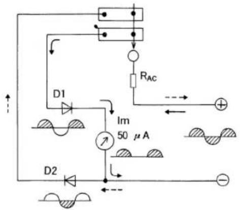
Fig 5-4 AC voltmeter principle
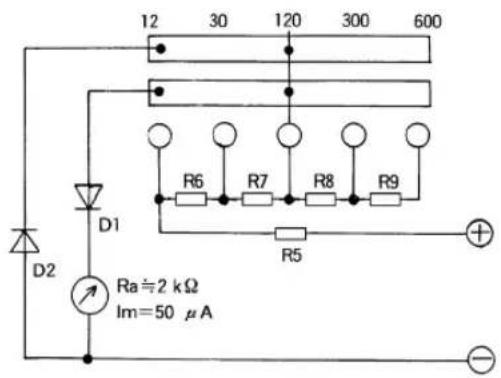
Fig 5-5 Equivalent circuit of AC12 V - 600 V
② AC30V
$$ \Omega = k ^ {} \times \boxed { * } \nabla^ {} * * \pm V / k 9 R \Omega \tag {AC30} $$
$$ R = R _ {(6)} - R _ {3 0 A C} - R _ {1 2 A C} = \boxed { * * } k \Omega - \boxed { * * } k \Omega = \boxed { * * } k \Omega $$
③ AC120V
$$ \mathrm{R} _ {(\mathrm{AC120})} = 9 \mathrm{k} \Omega / \mathrm{V} \times \boxed { * * } \mathrm{V} = \boxed { * * } \mathrm{k} \Omega = \boxed { * * } \mathrm{M} \Omega $$
$$ R = R _ {(\text { A }) \overline {{1 2 0}}} R _ {(3 0) \overline {{C}}} = \boxed { * * } k \Omega - \boxed { * * } k \Omega = \boxed { * * } k \Omega $$
④ AC300V
$$ R _ {(3 0 0) \mathrm{C}} = 9 \mathrm{k} \Omega / \mathrm{V} \times * * * * \mathrm{V} = * * * * \mathrm{k} \Omega = * * * * \mathrm{M} \Omega $$
$$ R = R _ {8 (3 0 0) \overline {{C}}} - R _ {(A C 1 2 0)} = \boxed { * * } M \Omega - \boxed { * * } M \Omega = \boxed { * * } M \Omega $$
⑤ AC600V
$$ R _ {(6 0 0 \mathrm{AC}} = 9 \mathrm{k} \Omega / \mathrm{V} \times * * * * \mathrm{V} = * * * * \mathrm{k} \Omega = * * * * \mathrm{M} \Omega $$
$$ R = R _ {(9)} - R _ {6 0 0 A C} - \boxed { * * } M \Omega - \boxed { * * } M \Omega = \boxed { * * } M \Omega $$
5-5 Ohm meter (Ω) circuit
The key point in calculation of an ohm meter circuit is that the circuit uses a zero adjuster to compensate consumption of the batteries. The setting conditions for the ohm meter circuit are :
Adjustable range of the battery voltage 2.5V - 3.5V or more
Central scale value of the meter (internal resistance)
$$ \left( \begin{array}{l l} \Omega \times 1 \mathrm{krange}: & 2 0 \mathrm{k} \Omega \ \Omega \times 1 0 \text {range}: & 2 0 0 \Omega \ \Omega \times 1 \text {range}: & 2 0 \Omega \end{array} \right. $$
① Zero Ω adjustment circuit
The lowest limit of the adjustable range of the battery voltage, 2.5V, is the value to be adopted when the remaining electricity of the batteries is lowest. The zero adjuster (VR) will be adjusted to 0 (Point "a") in view of the role of the variable resistance in the whole circuit. From the equation of Ohm's law (2), the equivalent internal resistance R_(2.5) between the terminals is

Fig 5-6 Zero adjustment circuit diagram
※Here we use the actual value of the circuit resistance, though R _18 is calculated to be 38 kΩ on Page 48.
$$ \begin{array}{l} \mathrm{R} _ {(2. 5)} = \frac {\mathrm{E} _ {(2 . 5)}}{\mathrm{Im}} = \frac {\boxed { * * } \mathrm{V}}{\boxed { * * } \mu \mathrm{A}} \ = \frac {\square \mathrm{V} ^ { * }}{\square \times \text { A10 }} = \boxed {* 1 0 ^ {3}} \quad \Omega = \square k ^ {2} \ \end{array} $$
In Fig 5-6, the internal resistance between the Point “a” and the ⊙ terminal, Ra, is
$$ \mathrm{Ra} = \frac {\mathrm{r} \times \mathrm{R} _ {0}}{\mathrm{r} + \mathrm{R} _ {0}} = \frac {\square}{\square} \frac {\square}{\Omega + \square} \frac {\mathrm{k} ^ { * } \mathrm{k} ^ { * }}{\mathrm{k} ^ {* 2} (\text {to two decimal places})} $$
Therefore, in order to make the meter work full-scale when E = 2.5V,
$$ R _ {1 6} = R _ {(2. 5)} - R a = \boxed { * * } k \Omega - \boxed { * * } k \Omega = \boxed { * * } k \Omega $$
For the highest limit of the adjustable range of the battery voltage, E (max), on the contrary, the zero adjuster will be adjusted to the full, 10k (Point “c”). The internal resistance between Point “c” and the terminal, Rc, is
$$ \begin{array}{l} \mathrm{Rc} = \frac {(\mathrm{r} + \mathrm{VR}) \times \mathrm{R} _ {1 8}}{\mathrm{r} + \mathrm{VR} + \mathrm{R} _ {1 8}} = \frac {\left(\square \quad \square \quad \square \quad \text {)} \quad \square \quad k ^ { } k ^ { } k ^ { } k ^ { * } \right.}{\square \quad \square \quad \square \quad \square \quad k ^ { } k ^ { } k ^ { } k ^ { * }} \ \cong \boxed { * * } \mathrm{k} \Omega (\text { round off to the second decimal place }) \ \end{array} $$
When the meter is made to work full-scale, the voltage between the Point “c” and the terminal is
$$ E c = I \cdot R = i m \times (r + V R) = \boxed { * * } \mu A \times (\boxed { * * } k \Omega + \boxed { * * } k \Omega) $$
$$ \cong \boxed { * * } \times 1 0 ^ {- 3} \mathrm{V} = \boxed { * * } \mathrm{mV} $$
The electric current that passes through R_18 , Ic, is
$$ \mathrm{Ic} = \frac {\mathrm{Ec}}{\mathrm{R} _ {1 8}} = \frac {\boxed { * * } \times 1 0 ^ {- 3} \mathrm{V}}{\boxed { * * } \times 1 0 ^ {3} \Omega} \cong \boxed { * * } \times 1 0 ^ {- 6} \mathrm{A} = \boxed { * * } \mu \mathrm{A} (\text {to one decimal place}) $$
The current that flows from the batteries, I (max), is
$$ \mathrm{I} (\max) = \mathrm{im} + \mathrm{Ic} = \boxed { * * } \mu \mathrm{A} + \boxed { * * } \mu \mathrm{A} = \boxed { * * } \mu \mathrm{A} $$
From Ohm's law, the battery voltage at the Point "c" of the zero adjuster, E (max), is
$$ \mathrm{E} (\max) = \mathrm{I} (\max) \times \left(\mathrm{Rc} + \mathrm{R} _ {1 6}\right) = \boxed { * * } \mu \mathrm{A} \times \left(\boxed { * * } \mathrm{k} \Omega + \boxed { * * } \mathrm{k} \Omega\right) $$
$$ \cong \boxed { * * } \mathrm{V} (\text { round off to the second decimal place }) $$
The value thus satisfies the setting condition, 3.5V.
Next, we will look into the position of the brush of the zero adjuster when the battery voltage (initial voltage) is 3.2V. When we assume the position to be the Point “b” in Fig 5-6, we will obtain the following from the conditions “0 at 2.5V and 10k at 3.6V”:
$$ \mathrm{Rab} = 1 0 \mathrm{k} \Omega \times \frac {(3 . 2 - 2 . 5) \mathrm{V}}{(3 . 6 - 2 . 5) \mathrm{V}} = 6. 4 \mathrm{k} \Omega $$
$$ \mathrm{Rbc} = 1 0 \mathrm{k} \Omega \times \frac {(3 . 6 - 3 . 2) \mathrm{V}}{(3 . 6 - 2 . 5) \mathrm{V}} = 3. 6 \mathrm{k} \Omega $$
This suggests that the position of the zero adjuster brush will be the point that divides the variable resistor to be 6.4k and 3.6k .
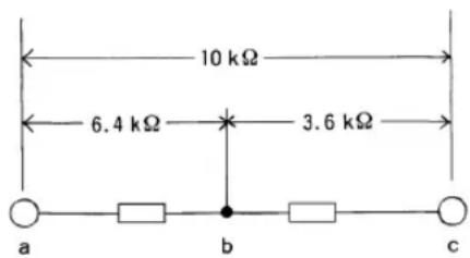
Fig 5-7
The internal resistance between Point "b" and the ⊖ terminal is
$$ \begin{array}{l} \mathrm{Rb} = \frac {(\quad +) (\quad)}{+ + + + \mathrm{RRbcRabr}} \ = \frac {(\boxed { }) ^ {} (k \Omega + \boxed { * * } k \Omega \times \boxed { * * } k \Omega + \boxed { * * } k \Omega}{\boxed { * * } k \quad \boxed { * * } k \quad \boxed { * * } k \quad \boxed { * * } k \Omega + \Omega + \Omega + \Omega} \ = \boxed { * *} \mathrm{k} \Omega (\text { round off to the third decimal place }) \ \end{array} $$
The equivalent internal resistance between the terminals, when the battery voltage is 3.2V, is hence
R_(3.2) = Rb + R_16 = *k + k ***k (round down the decimal point)
② × 1k
Since the central scale value R (internal resistance) of the specifications is 20k , the shunt resistor R_15 is, from the equation (7) (see Page 20), as follows :
$$ \mathrm{r} _ {1} = \frac {\mathrm{r} _ {2} \times \mathrm{R}}{\mathrm{r} _ {2} - \mathrm{R}} $$
Here, R = 20kΩ,
$$ \mathrm{r} _ {1} = \mathrm{R} _ {1 5}, \text { and } \mathrm{r} _ {2} = \mathrm{R} _ {(3. 2)} = 5 5 \mathrm{k} \Omega $$
$$ R _ {1 5} = \frac {\boxed { * * } k \Omega \times \boxed { * * } k \Omega}{\boxed { * * } k - \boxed { * * } k \Omega} $$
$$ \cong \boxed { * * } \mathrm{k} \Omega (\text { round off the second decimal place }) $$
③ × 10
$$ \mathrm{R} = 0. 2 \mathrm{k} \Omega (2 0 0 \Omega), \mathrm{r} _ {1} = \mathrm{R} _ {1 4}, \text {and} \mathrm{r} _ {2} = \mathrm{R} _ {(3. 2)} = 5 5 \mathrm{k} \Omega $$
$$ R _ {1 4} = \frac {\boxed { * * } k \Omega \times \boxed { * * } k \Omega}{\boxed { * * } k - \boxed { * * } k \Omega} = \boxed { * * } k \Omega \cong \boxed { * * } \Omega (\text { to one decimal place }) $$
④ × 1
$$ \mathrm{R} = 0. 0 2 \mathrm{k} \Omega (2 0 \Omega), \mathrm{r} _ {1} = \mathrm{R} _ {1 3}, \text { and } \mathrm{r} _ {2} = \mathrm{R} _ {(3. 2)} = 5 5 \mathrm{k} \Omega $$
$$ R _ {1 3} = \frac {\boxed { * * } k \Omega \times \boxed { * * } k \Omega}{\boxed { * * } k - \boxed { * * } k \Omega} = \boxed { * * } k \Omega \cong \boxed { * * } \Omega (\text {to two decimal places}) $$
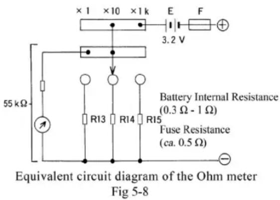
The actual circuit has a resistance of ca. 1.9 due to the fuse and the batteries (two battery cells). This should be subtracted from the calculated value. (The resistance is negligible for other ranges because the value of the resistance is large.) Then,
$$ \mathrm{R} _ {1 3} = \mathrm{R} _ {1 3} - 1. 9 \Omega = \boxed { * * } \Omega - 1. 9 \Omega \cong \boxed { * * } \Omega $$
5-6 Battery check circuit (1.5V)
The battery check circuit connects a load resistance of 18 to the battery to be checked and the DC3V-voltmeter measures the terminal voltage. This allows examination at nearly the same conditions as in use and hence provides the method to determine whether the battery is functioning or has been used up.
● Example of calculation for battery check (the case of 1.6V)
Effective resistance between the two terminals, R_0 , is
$$ R _ {0} \quad 0. 5 = + \Omega \frac {\left(R _ {3} + R m\right) \times R _ {1 3}}{3 + R + R R m} $$
$$ 0. 5 + \Omega \frac {\boxed { * * } k + \boxed {2} * * * k \Omega) \times \boxed { * * } \Omega}{\boxed { * * } k + \boxed { * * } k + \boxed {2} * * * \Omega} $$
= 0.5 + = * (to two decimal places) When the voltage of the measured battery is 1.6V, the current that flows through this circuit, I_0 , is hence
$$ \mathrm{I} _ {0} = \frac {\mathrm{E}}{\mathrm{R} _ {0}} = \frac {\boxed { * * } \mathrm{V}}{\boxed { * * } \Omega} = \boxed { * * } \mathrm{mA} (\text {to one decimal place} $$
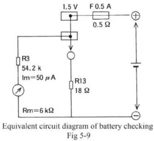
The current that flows through the meter circuit, im, is hence
$$ \mathrm{im} = \frac {\mathrm{R} _ {1 3}}{\mathrm{R} + \mathrm{RR} _ {3} \mathrm{m}} \times \mathrm{I} _ {0} = \frac {\boxed { * * } \Omega}{\boxed { * * } \mathrm{k} \Omega} \times \boxed { * * } \mathrm{mA} = \boxed { * * } \mathrm{mA} = \boxed { * * } \mu \mathrm{A} $$
(to four decimal places)
The position of each graduation on the scale plate is determined for each voltage by calculation of what percentage of Im im corresponds to.
KIT-8D Type circuit diagram
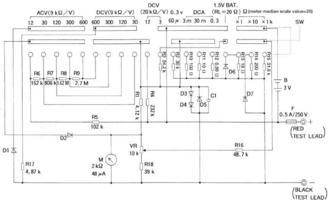
For this product, KIT-8D, the answer values obtained from the calculation so far may differ from the values of the resistors used in the actual circuit. This is because the product adopts a set of resistors called 'series resistances'. A series resistance is based on a progression of preferred numbers that indicates what kind of number is in the set of resistances. The typical sequences include E24 series, E96 series, etc. These progressions are also defined in the JIS standard. Use of series resistances has the advantage in cost and availability.
VI Assembly of buzzer kit (optional accessory)
1. Principle
1-1 Principle of a piezoelectric buzzer
A piezoelectric buzzer element has a simple structure - corhuric elemento and a diaphragm are bonded together. When an AC voltage is applied, the piezo element, the element will expand and contract in the radial direction. A buzzer movement to generate sound by making the diaphragm bend repeatedly.
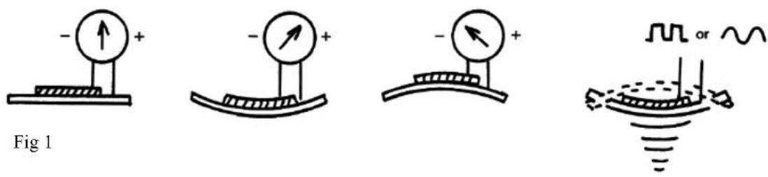
1-2 Principle of oscillator circuit
The circuit used in the buzzer circuit in the circuit diagram shown in 2. on Page 57 is an oscillator circuit called “Astable Multivibrator”.
This circuit uses two transistors and other components such as resistors and capacitors to output square waves (Fig 3) by periodical repetition of ON and OFF of the transistors. This product, KIT -8D, uses this circuit as an oscillator circuit to oscillate the buzzer. Simple explanation of the mechanism is given below using Fig 2 and 3 : When one transistor is OFF, base current flows through the other transistor by 10k Ω-base resistance and the transistor is kept at ON ; at the same time, the capacitor connected to the OFF - transistor is discharging through the resistor connected to the OFF side.
When this discharge reaches the time constant (time) determined by the capacitor and the resistance, the OFF-transistor is switched ON and the ON-transistor is switched OFF.
Repeated operation of this gives the output of square waves.
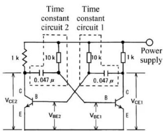
Fig 2 A stable multivibrator circuit
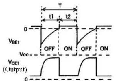
line
| Time | V_BE1 | V_CCE1 | |------|-------|--------| | t1 | OFF | ON | | t2 | OFF | ON |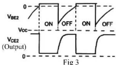
line
| Time Segment | V_BE2 | V_Ce2 | | ------------ | ----- | ----- | | 0 | 0 | 0 | | ON | High | Low | | OFF | Low | High | | ON | High | Low | | OFF | Low | High |Operation Waveform
2. Circuit Diagram
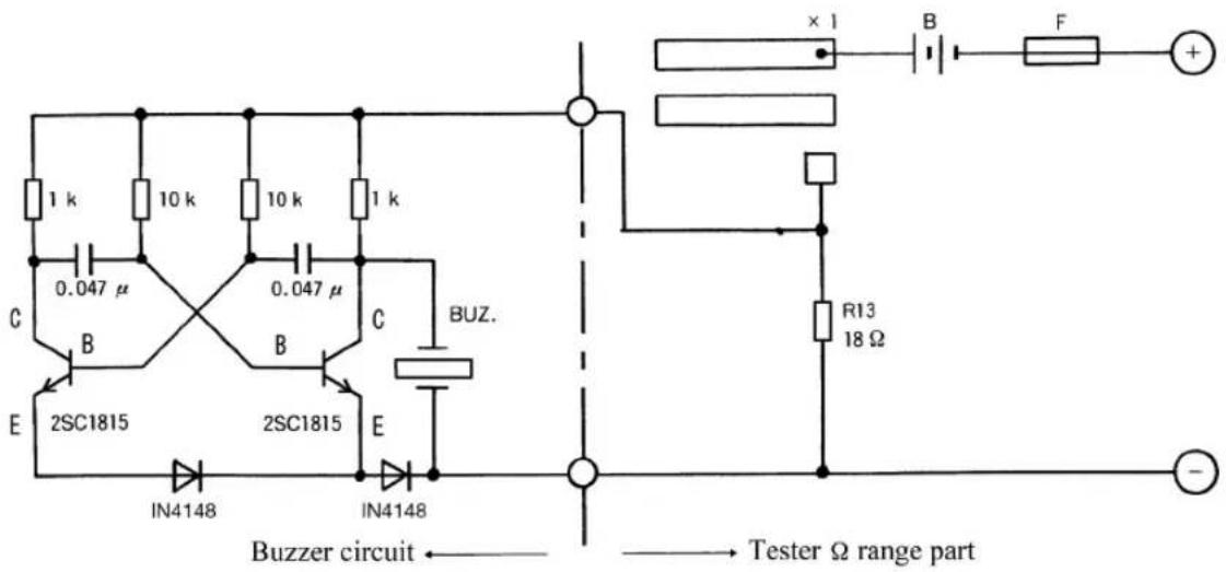
3. Parts List
| Item Standard Quantity | Item Standard Quantity | ||||
| Piezoelectric buzzer element | Two-terminal type, 20mm | 1 | Printed board | Small board for soldering practice | 1 |
| Transistors 2SC1815 GR 2 Lead wire | Red 68mm 1 | ||||
| Capacitors | 0.047 | 2 | Lead wire Black | 70mm 1 | |
| Diodes | IN4148 | 2 | Tapping screw | 2 × 6 1 | |
| Fixed resistors | 1/4W 1kF 2 * | Adhesive | Polyvinyl acetate emulsion adhesive | Small amount | |
| Fixed resistors | 1/4W 10kF | 2 | Solder | Remainder of assembly of the main body | Small amount |
※ We notify that the adhesive is not included in the parts bag of the buzzer kit.
4. How to attach the piezoelectric buzzer element
Remove grease or dust from the surface of the panel and the diaphragm (brass plate of the piezoelectric buzzer element). Apply adhesive onto about three places around the step as illustrated in Fig 1. (Note) For convenience, use a plastic oil feeder to apply adhesive. Places to:
2 Put the diaphragm in so that the lead the buzzer element come to the direction of the cutting of the place to be attached. Press lightly to prevent it from rising. The ideal method is that the overflows and falls onto the diaphragm as Fig 2.
Places to apply adhesive
wires from
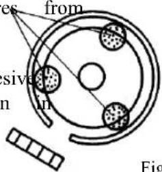
Fig 1
3 Put the lead wires of the buzzer element through the positions indicated in Fig 3 and fix them from above by applying adhesive on the connections. Leave for about 16 hours to dry.
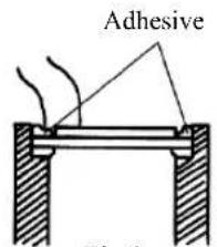
Fig 2
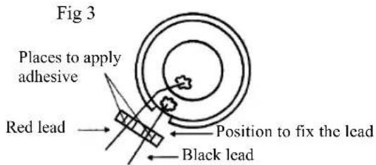
5. Assembly and wiring of the printed board
Mount each component by referring the stereoscopic wiring diagram shown below (Fig 4). Wire the black and red leads of the small board to the large printed board of the main body (Fig 5 and 6).
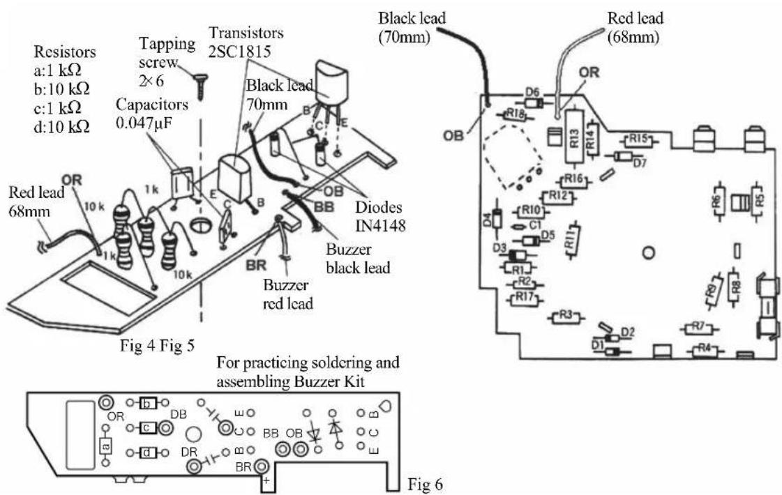
6. Installation of the printed board
Install the completed small board to the panel.
1 Put the large printed board and install the small board to indicated in Fig 7. Be careful to arrange the wires so wiring of the boards is not pinched between other parts.
2 Fix the small board to the pane tapping screw.
3 Put the body case and the panel together and screw the case stopper screw to completely.
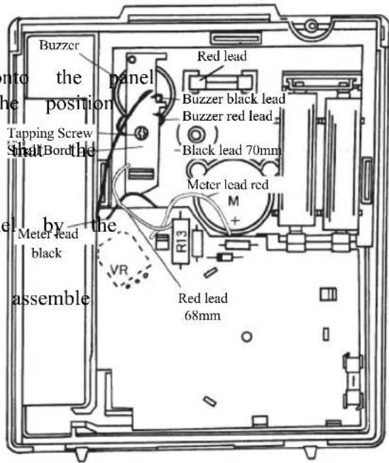
7. Measurement method
⚠ Warning
- Always carry out 'range check' for each measurement.
- Do not switch to other ranges during measurement.
- Never carry out measurement when your hand is wet.
- Circuits to which voltage is applied cannot be measured.
1) Objects to be measured
Check of conduction of wiring, etc.
2) Measurement range
Use × 1 range of the resistance measurement
3) Measurement method
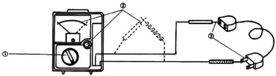
1 Adjust the range selector knob to × 1 of the range.
2 Short-circuit the tips of both test pins to perform zero Ω adjustment.
(The tester will generate buzzer sound.)
3 Connect the test pins to the object to be examined.
4 Check the connection by the buzzer sound and the scale plate.
- The buzzer will generate sound at less than ca. 35 . The sound may be difficult to catch at levels around this value.
Parts list sheet
| Rated Value Place to stick | Color code/symbol | |||||
| R1 4.12 kΩF | Yellow | Brown | Red | Brown | Brown | |
| R2 30 kΩJ | Orange | Black | Black | Red | Gold | |
| R3 54.2 kΩF | Green | Yellow | Red | Red | Brown | |
| R4 232 kΩF | Red | Orange | Red | Orange | Brown | |
| R5 102 kΩF | Brown | Black | Red | Orange | Brown | |
| R6 162 kΩF | Brown | Blue | Red | Orange | Brown | |
| R7 806 kΩF | Grey | Black | Blue | Orange | Brown | |
| R8 1.62 MΩF | Brown | Blue | Red | Yellow | Brown | |
| R9 2.7 MΩF | Red | Purple | Black | Yellow | Brown | |
| R10 102 ΩF | Brown | Black | Red | Black | Brown | |
| R11 10 ΩF | Brown | Black | Black | Gold | Brown | |
| R12 0.99 ΩF | Black | White | White | Silver | Brown | |
| R13 18 ΩF | Brown | Grey | Black | Gold | Brown | |
| R14 200 ΩG | Red | Black | Black | Black | Red | |
| R15 31.6 kΩF | Orange | Brown | Blue | Red | Brown | |
| R16 48.7 kΩF | Yellow | Grey | Purple | Red | Brown | |
| R17 4.87 kΩF | Yellow | Grey | Purple | Brown | Brown | |
| R18 39 kΩJ | Orange | White | Black | Red | Gold | |
| D1 IN4148 | ||||||
| D2 IN4148 | ||||||
| D3 IN4004 | ||||||
| D4 IN4004 | ||||||
| D5 IN4004 | ||||||
| D6 IN4004 | ||||||
| D7 IN4004 | Place to stick | |||||
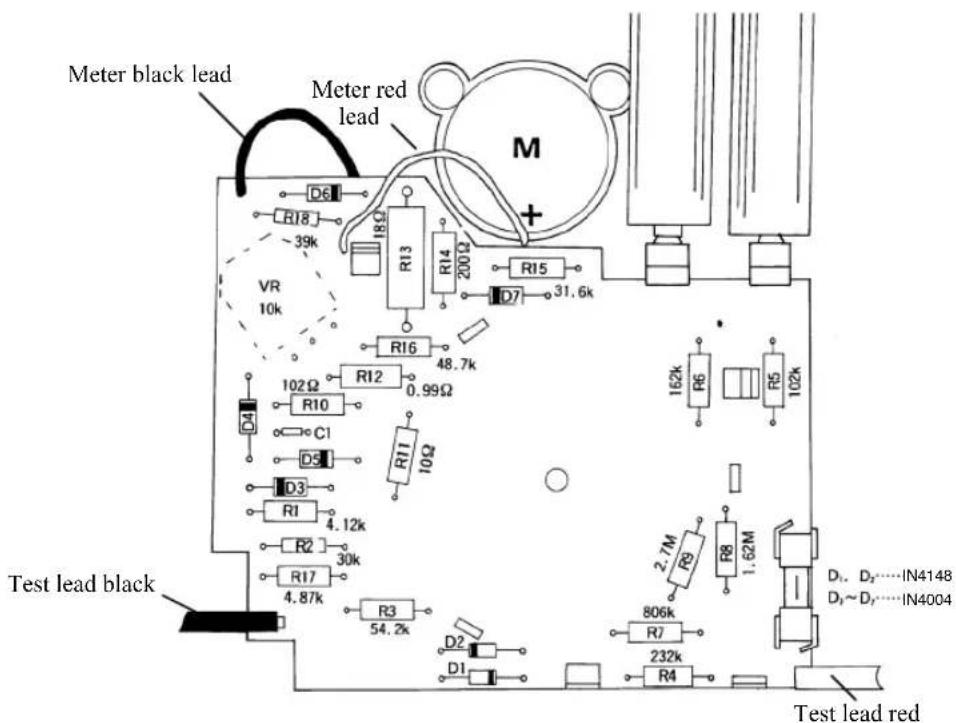
MEMO
MEMO
MEMO
© Books for reference
The following reference books are available, which explain the construction and principle of the tester and the relevant measuring methods in an easy-to-understand manner:
- “100% Effective Use of Your New Tester” published by CQ Publishing Co., Ltd.
- “Effectively Using Your Digital Tester” published by Tetsugaku shuppan Co., Ltd.
| Class | |
| Name |
sanwa®
Sanwa Electric Instrument Co., Ltd.
Head Office: Dempa Building, 2-4-4 Sotokanda,
Chiyoda-ku, Tokyo 101-0021 Japan
Phone: 81-3-3253-4871
Osaka Sales Office: 2-7-2 Ebisu-nishi, Naniwa-ku,
Osaka City 556-0003 Japan
Phone: 81-6-6631-7361