SA9Z-CM8K-4S2 - Uncategorized Idec - Free user manual and instructions
Find the device manual for free SA9Z-CM8K-4S2 Idec in PDF.

| Product Type | Industrial Electronic Module |
| Brand | Idec |
| Model | SA9Z-CM8K-4S2 |
| Dimensions (W x H x D) | 80 mm x 80 mm x 50 mm |
| Weight | 150 g |
| Material | Plastic housing, metal terminals |
| Input Voltage | 24 V DC |
| Output Type | Relay output |
| Number of Channels | 4 |
| Current Rating per Channel | 2 A |
| Protection Rating | IP20 |
| Operating Temperature | -20°C to +55°C |
| Mounting | DIN rail mount |
| Connection Type | Screw terminals |
| Indicators | LED status per channel |
| Compliance | CE, RoHS |
| Main Functions | Switching, signal isolation |
| Maintenance | Clean with dry cloth |
| Safety Precautions | Disconnect power before servicing |
| Spare Parts Availability | Replace whole module |
| Repairability | Not repairable; replace if defective |
Frequently Asked Questions - SA9Z-CM8K-4S2 Idec
User questions about SA9Z-CM8K-4S2 Idec
0 question about this device. Answer the ones you know or ask your own.
Ask a new question about this device
Download the instructions for your Uncategorized in PDF format for free! Find your manual SA9Z-CM8K-4S2 - Idec and take your electronic device back in hand. On this page are published all the documents necessary for the use of your device. SA9Z-CM8K-4S2 by Idec.
USER MANUAL SA9Z-CM8K-4S2 Idec
Confirm that the delivered product is what you have ordered. Read this instruction sheet to make sure of correct operation. Make sure that the instruction sheet is kept by the end user.
SAFETY PRECAUTINS
In this operation instruction sheet, safety precautions are categorized in order of importance to Caution.

CAUTION
Caution notices are used where intention might cause personal injury or damage to equipment.

For safety use of a laser product
CAUTION
- Caution - Use of controls or adjustments or performance of procedures other than those specified in this manual may result in hazardous radiation exposure.
- This product omits a visible laser beam. Do not stare into the bear directly. Furthermore, do not look the laser which is reflected at a mirror-like object.
- About safety standards of laser product, IEC60825-1 "Safety of laser products" has been stipulated by the IEC(International Electrotechnical Commission). This product is classified as "CLASS1 product" according to IEC60825-1.
This product complies with 21 CFR 1040.10 and 21 CFR 1040.11 according to Laser Notice No.50, dated June 24, 2007, issued by CDRH(Center for Devices and Radiological Health) under FDA(Food and Drug Administration).
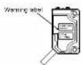
Following "Warning label" and "Certification/Identification label" are affixed on this product according to IEC 60825-1 and Isser regulation of FDA. When this product will be incorporated into final device system which is exported to the USA, make sure that Certification/Identification label is affixed.


Type
| SA1E-□□□□ | |
| T : Through beam | blank : Cable (1m) |
| P : Polarized retro-reflective | -2M : Cable (2m) |
| B : Background suppression | -5M : Cable (5m) |
| C : Connector (M8) | |
| N : NPN Output | 3 : Light ON / Dark ON |
| P : PNP Output | |

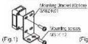
Installation
- Do not apply excessive impact on the sensor during the installation process, so as to prevent damage or deterioration in the degree of protection.
• To install the sensor, tighten the mounting screws to a torque of 0.5N·m or less. (Fig.1)
• Install the Background suppression type sensor head perpendicular to the object transfer as shown below to minimize sensing errors. (Fig.2)


| Polarized retroreflective | Background suppression | |
| SA1E-LPN3 | SA1E-LBN3 | |
| SA1E-LPP3 | SA1E-LBP3 | |
| (mm) | ||
| Operating range 10 to 30V DC) | ||
| 35mA maximum | ||
| 0.3 to 10mReflector: (ACR5R8R9)2 | 20 to 300mm(White paper 200x200mm) | |
| - | 40 to 300mm | |
| - | 10% | |
| q6mm opaque object (at 3m) | φ0.2mm copper wire (at 170mm) | |
| (lectable) | ||
| 1 : 100mA maximum Voltage drop : 1.5V maximum | ||
| Protected Reverse polarity protection, Lead short circuit protection, Interference praven | ||
| °C (no freezing and condensation) | ||
| RH (no condensation) | ||
| (b-cbsn type), 0.2fptnm/2m5m catbrye cable | ||
| Detection System | Through-beam | Polarized retroreflective | Background suppression | |
| TYPE No. | NPN Output | SA1E-LIN3 | SA1E-LPNS | SA1E-LBND |
| PNP Output | SA1E-LTP3 | SA1E-LPPS | SA1E-LBPS | |
| Light Source | Red Laser dose(Emission wavelength: 650nm)IEC/US CLASS1Maximum output: 7mW | |||
| Power Voltage | 12 to 24V DC Ripple p-p 10% maximum (Operation range 10 to 30V DC) | |||
| Current Consumption | Emitter: 15mA maximumReceiver: 30mA maximum | 35mA maximum | ||
| Sensing Range | 30m | 0.3 to 10mReflector: ACR5R8R9^2 | 20 to 300mm(White paper: 200×200mm) | |
| Adjustable setting range | - | - | 40 to 300mm | |
| Hysteresis | - | - | 10% | |
| Minimum sensing object(type) | q66nm opaque object(at 3m) | q66nm opaque object(at 3m) | q0.2mm copper wire(at 170mm) | |
| Control Output | Open collector output (NPN / PNP output selectable)Load voltage: 30V DC maximum, Load current: 100mA maximum, Voltage drop: 1.5V maximumLight-ON/Dark-ON switch selectable | |||
| Protection Circuit | Reverse poverty protection, Load short circuit protected. Reverse polarity protection, Lead short circuit protection, Interference praven | |||
| Response Time | 250us maximum | |||
| Ambient Temperature ^2 | Coating: -10 to +56 °C, Storage: -25 to +70 °C (no freezing and condensation) | |||
| Ambient Humidity | Operating: 35 to 85% RH, Storage: 35 to 85% RH (no condensation) | |||
| Degree of protection | IP67 (IEC60525) | |||
| Material | Housing, PBT, Lens, PMMA, Display, PC | |||
| Cable | q3.5mm, 3-core(2-core for emitter of through-beam type), 0.27mm(2m5m cable) cable | |||
*1: This product complies with 21CFR 1040.10 and 1040.11 based on Notice No.50.
*2. Maintain at least the following distance between the sensor and reflector: IAC-R5/R6/R9 : 300mm
-3: Maximum operating temperature is 50°C when using this product as DUE-OL used products.
5 Notes for Operation
- Do not use the sensor during the transient time of 100 ms after turning on the power supply.
- If the sensor and the load are connected to different power supplies, the sensor must always be turned on first.
- Do not install the sensor outdoors, nearby induction device, or heat source. Choose locations free from frequent vibrations, shocks, dust, toxic gases, water, oil, and chemicals, so as to prevent malfunctions and damage.
- Do not expose the sensor to sunlight or other direct light projections.
- Do not use the sensor with drops of water remaining on the lens or aperture of slits.
- In case installing the reflector of polarized retro-reflective type, make fine adjustment of angle or position of the sensor or reflector.
This product emits high directional beam. Therefore the beam possibly be out of alignment by the mounting condition. Make sure to adjust the beam axes alignment before use.
CAUTION
• Do not connect the sensor to AC power supply, so as to prevent explosion and burning.
6 Wiring
• Turn off the power supply before wiring.
- Connect correctly to prevent damage.
- The power voltage must not exceed the rated range.
- When using a switching power supply, be sure to ground the FG (frame ground) terminal.
- Do not install the sensor wiring in the same conduit with high-voltage lines and power lines.
- Cable extension is allowed up to 100m using a cablyre cable with co-wires of 0.3 mm² or more.
• To connect the sensor with connector cable, lighten connector to a torque of 0.5N · m or less.
- Use a UL Listed (CYJV/CYJV7) mailing connector/cord assembly when using connector type as UL/o-UL listed products.
WIRING DIAGRAM
NPN Output Type


Connector pin assignment
PNP Output Type


Corredet pr
Through-beam Type (Emitter)


Corrected pin assignment
7 Adjustment for Background suppression type
| Step | Distance Control | Adjusting Procedure |
| 1 | Install a photoelectric sensor and the sensing object. Turn the control counter-clockwise until the operation LED turns OFF. (*1). Then turn clockwise until the operation LED turns ON (point A). | |
| 2 | Remove the sensing object, then the operation LED turns OFF. Turn clockwise until the operation LED turns ON (The background is detected) (point B). (*2) | |
| 3 | Set the middle point between point A and B as point C. (*3) |
*1: If the operation LED turned off, turn on by turning the control clockwise.
2: Make one turn or more clockwise from point A and set the position as point C when the background is too far and the operation LED dose turn ON.
*3. There may be more than 1 turn between points A and B, since this photoelectric sensor incorporates a 6-turn adjuster.

(4) Sensing Range Control
8-form-endless
Fish by Indicolor (Green)
*4: Sensing range becomes longer when turned clockwise.

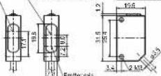
Dimensions
• CABLE TYPE
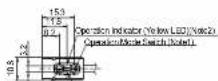
Stability Indicator (Green LED/Indic)
Conservative Control process for BGS TYP2L/Nelnd
Sensing Range Control for BGS Type
[Enter and Enter]
Through-Beam Pointed Retro-Reflective Background Suppression
• CONNECTOR TYPE
Sensitivity Indicator (Green, FID, Noted) Sensitivity Control Interval for DSS TYPE (Noted) Sensing Range Control for BGE type
Embraer's Embra

Through-Beam Polar and Retro-Reflective Background Suppression
Note1: Stability Indicator and Sensitivity Control and Operation Mode
Note2: Power Indicator (Green LED) is attached to the Emitter of
Through-Beam Type instead of Operation Indicator.
IDEC CORPORATION
http://www.idec.com
2012.3