
36IRB - Gril salamandre Vulcan - Free user manual and instructions
Find the device manual for free 36IRB Vulcan in PDF.


| Product type | Induction cooktop |
| Brand | Vulcan |
| Model | 36IRB |
| Dimensions (W x D x H) | 90 x 52 x 5 cm |
| Net weight | 15 kg |
| Power supply | 220-240 V, 50-60 Hz, 7.2 kW |
| Number of cooking zones | 4 induction zones |
| Main functions | Induction cooking, touch controls, timer, keep warm function, pan detection |
| Care and cleaning | Clean with a soft damp cloth, avoid abrasive products |
| Safety | Child lock, automatic safety shutdown, residual heat indicator |
| Spare parts and repairability | Repairability index: 7.5/10, spare parts available through Vulcan after-sales service |
| General information | Built-in cooking appliance, energy class A+, CE certified |
Frequently Asked Questions - 36IRB Vulcan
User questions about 36IRB Vulcan
0 question about this device. Answer the ones you know or ask your own.
Ask a new question about this device
Download the instructions for your Gril salamandre in PDF format for free! Find your manual 36IRB - Vulcan and take your electronic device back in hand. On this page are published all the documents necessary for the use of your device. 36IRB by Vulcan.
USER MANUAL 36IRB Vulcan
INSTALLATION & OPERATION MANUAL FOR Salamander Broilers
ITW Food Equipment Group

VULCAN
MODELS
36RB
36IRB

MODELS
C36RB
C36IRB
www.vulcanequipment.com
www.wolfequipment.com
36RB/36IRB

natural_image
Exterior view of a VULCAN industrial oven with control knobs and internal grating (no visible text or symbols beyond branding)IMPORTANT FOR YOUR SAFETY
THIS MANUAL HAS BEEN PREPARED FOR PERSONNEL QUALIFIED TO INSTALL GAS EQUIPMENT, WHO SHOULD PERFORM THE INITIAL FIELD START-UP AND ADJUSTMENTS OF THE EQUIPMENT COVERED BY THIS MANUAL.
POST IN A PROMINENT LOCATION THE INSTRUCTIONS TO BE FOLLOWED IN THE EVENT THE SMELL OF GAS IS DETECTED. THIS INFORMATION CAN BE OBTAINED FROM THE LOCAL GAS SUPPLIER.
IMPORTANT
IN THE EVENT A GAS ODOR IS DETECTED, SHUT DOWN UNITS AT MAIN SHUTOFF VALVE AND CONTACT THE LOCAL GAS COMPANY OR GAS SUPPLIER FOR SERVICE.
FOR YOUR SAFETY
DO NOT STORE OR USE GASOLINE OR OTHER FLAMMABLE VAPORS OR LIQUIDS IN THE VICINITY OF THIS OR ANY OTHER APPLIANCE.
WARNING: IMPROPER INSTALLATION, ADJUSTMENT, ALTERATION, SERVICE OR MAINTENANCE CAN CAUSE PROPERTY DAMAGE, INJURY OR DEATH. READ THE INSTALLATION, OPERATING AND MAINTENANCE INSTRUCTIONS THOROUGHLY BEFORE INSTALLING OR SERVICING THIS EQUIPMENT.
IN THE EVENT OF A POWER FAILURE, DO NOT ATTEMPT TO OPERATE THIS DEVICE.
INSTALLATION, OPERATION AND CARE OF SALAMANDER BROILERS
GENERAL
Salamander Broilers are produced with quality workmanship and material. Proper installation, usage, and maintenance of your broiler will result in many years of satisfactory performance.
It is suggested that you thoroughly read this entire manual and carefully follow all of the instructions provided.
Accessories are sold separately for the Salamander Broiler:
| Radiant Altitude Kits | |
| Accessory Number | Description |
| ALTISR-N01 | KIT, RB ALTITUDE NG SEA-1999FT |
| ALTISR-P02 | KIT, RB ALTITUDE LP SEA-1999FT |
| ALTISR-N03 | KIT, RB ALTITUDE NG 2000-3999FT |
| ALTISR-P04 | KIT, RB ALTITUDE LP 2000-3999FT |
| ALTISR-N05 | KIT, RB ALTITUDE NG 4000-6999FT |
| ALTISR-P06 | KIT, RB ALTITUDE LP 4000-6999FT |
| ALTISR-N07 | KIT, RB ALTITUDE NG 7000-8999FT |
| ALTISR-P08 | KIT, RB ALTITUDE LP 7000-8999FT |
| ALTISR-N09 | KIT, RB ALTITUDE NG 9000-10000FT |
| ALTISR-P10 | KIT, RB ALTITUDE LP 9000-10000FT |
| Common Accessories | |
| Accessory Number | Description |
| WALLMNT-CHRBKR | SST WALL MOUNT BRACKETS |
| COUNTER-ADJLEG | SET OF (4) 6” ADJUSTABLE LEGS |
| CONNECT-CHALL | KIT, SALAMANDER INTERPLUMBING |
| Infrared Altitude Kits | |
| Accessory Number | Description |
| ALTISI-N01 | KIT, RB ALTITUDE NG SEA-1999FT |
| ALTISI-P02 | KIT, RB ALTITUDE LP SEA-1999FT |
| ALTISI-N03 | KIT, RB ALTITUDE NG 2000-3999FT |
| ALTISI-P04 | KIT, RB ALTITUDE LP 2000-3999FT |
| ALTISI-N05 | KIT, RB ALTITUDE NG 4000-6999FT |
| ALTISI-P06 | KIT, RB ALTITUDE LP 4000-6999FT |
| ALTISI-N07 | KIT, RB ALTITUDE NG 7000-8999FT |
| ALTISI-P08 | KIT, RB ALTITUDE LP 7000-8999FT |
| ALTISI-N09 | KIT, RB ALTITUDE NG 9000-10000FT |
| ALTISI-P10 | KIT, RB ALTITUDE LP 9000-10000FT |
INSTALLATION
Before installing, verify that the type of gas supply (natural or propane) agrees with the specifications on the rating plate located underneath the broiler rack drip tray. If the supply and equipment requirements do not agree, do not proceed with the installation. Contact your dealer immediately.
UNPACKING
Immediately after unpacking, check for possible shipping damage. If the broiler is found to be damaged, save the packaging material and contact the carrier within 15 days of delivery.
Before installing, verify that the type of gas (natural or propane) and the clearance dimensions (see below) agree with the specifications on the rating plate which is located under the crumb tray on the right side.
LOCATION
The equipment area must be kept free and clear of combustible substances.
| Minimum ClearanceRear 0” 0” | Combustible Construction | Non-Combustible Construction |
| Sides (Infrared) 36IRB & C36IRB | 2” | 0” |
| Sides (Radiant) 36RB & C36RB | 6” | 0” |
| Bottom | 4” with legs | 0” |
The installation location must allow adequate clearances for servicing and proper operation. A minimum front clearance of 24" is required.
Do not obstruct the flow of combustion and ventilation air. Adequate clearance for air openings into the combustion chamber must be provided. Make sure there is an adequate supply of air in the room to replace air taken out by the ventilating system. Do not permit fans to blow directly at the broiler. Avoid wall-type fans which create air cross currents within the room. Avoid open windows next to the broiler. Allow for maximum clearance between the flue and hood ventilation system as per NFPA 96 requirements. Minimum 18" clearance is recommended for proper operation and for compliance with local building and fire codes.
INSTALLATION CODES AND STANDARDS
The broiler must be installed in accordance with:
In the United States of America:
In the United States of America:
- State and local codes.
- National Fuel Gas Code, ANSI-Z223.1/NFPA #54 (latest edition). This shall include but not be limited to: NFPA #54 Section 10.3.5.2 for Venting. Copies may be obtained from The American Gas Association Accredited Standards Committee Z223, @ 400 N. Capital St. NW, Washington, DC 20001 or the Secretary Standards Council, NFPA, 1 Batterymarch Park Quincy, MA 02169-7471
NOTE: In the Commonwealth of Massachusetts
All gas appliances vented through a ventilation hood or exhaust system equipped with a damper or with a power means of exhaust shall comply with 248 CMR.
- NFPA Standard # 96 Vapor Removal from Cooking Equipment, latest edition, available from the National Fire Protection Association, Batterymarch Park, Quincy, MA 02269.
In Canada:
- Local codes.
- CAN/CSA-B149.1 Natural Gas Installation (latest edition)
- CAN/CSA-B149.2 Propane Installation Code (latest edition), available from the Canadian Gas Association, 178 Rexdale Blvd., Etobicoke, Ontario, Canada M9W 1R3
GAS CONNECTIONS
CAUTION: All gas supply connections and any pipe joint compound used must be resistant to the action of propane gases.
Codes require that a gas shutoff valve be installed in the gas line ahead of the broiler.
NATURAL GAS: Standard orifices are set at 5" W.C. (Water Column). A pressure regulator is supplied and must be installed when the broiler is connected to the gas supply.
PROPANE GAS: Standard orifices are set at 10" W.C. (Water Column). A pressure regulator is supplied and must be installed when the broiler is connected to the gas supply.
The gas supply line must be 34 " or larger. If flexible or semi-rigid connections are used, the inside diameter must be the equivalent of 34 " iron pipe or larger. All connections of the flexible and semi-rigid type must comply with all local and national requirements. Make sure gas piping is clean and free of dirt, piping compound, and obstructions.
WARNING: PRIOR TO LIGHTING, CHECK ALL JOINTS IN THE GAS SUPPLY LINE FOR LEAKS. USE SOAP AND WATER SOLUTION. DO NOT USE AN OPEN FLAME.
After piping has been checked for leaks, all piping receiving gas should be fully purged to remove air.
GAS PRESSURE REGULATOR INSTALLATION
Gas regulator pressure is preset at 5" Water Column (W.C.) for natural gas, and 10" W.C. for propane gas. Minor adjustments may be required based on site specific gas pressure.
Install the regulator as close to the broiler on the gas supply line as possible. Make sure that the arrow on the underside of the regulator is oriented in the direction of gas flow to the broiler (Fig. 1) and the regulator is positioned with the vent plug and adjustment screw upright (Fig. 2). A recommended plumbing schematic is listed below only for Salamander units as guide to the installer and ITW Cooking Equipment or Hobart is in no way liable for plumbing installation (Fig. 3).

natural_image
Close-up of a mechanical component with bolt holes and internal features (no visible text or symbols)Fig. 1

natural_image
Close-up of a metallic industrial valve component with no visible text or symbolsFig. 2
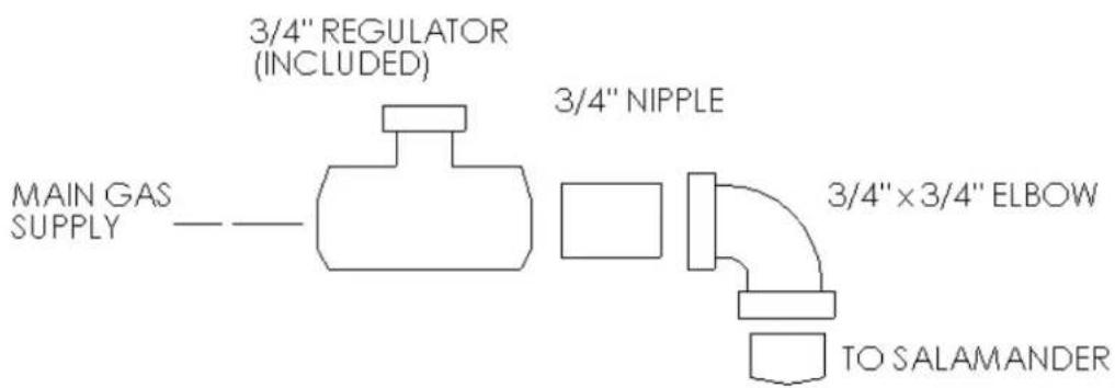
Fig. 3
The minimum supply pressure (upstream of the regulator) should be 7-9" W.C. for natural gas and 11-12" W.C. for propane gas. At no time should the regulator be connected to supply pressure greater than 12 psig (3.45 kPa) or 14" W.C.
FLUE CONNECTIONS
DO NOT obstruct the flow of flue gases from the flue located on the rear of the broiler. It is recommended that the flue gases be ventilated to the outside of the building through a ventilation system installed by qualified personnel.
Information on the construction and installation of ventilating hoods may be obtained from the standard for "Vapor Removal from Cooking Equipment," NFPA No. 96 (latest edition), available from the National Fire Protection Association, Batterymarch Park, Quincy, MA 02269.
ASSEMBLY
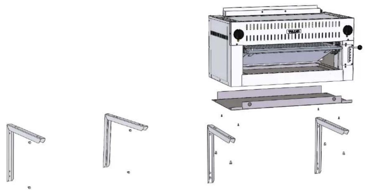
Salamander Broiler Mounted on a Wall (Fig. 4).
The separate wall mounting bracket accessory (WALLMNT-CHRBKR) will be needed to wall mount the unit.
- Follow the combustible/noncombustible clearance guidelines that are listed in the "Installation" section in this manual.
- Make sure brackets are level and properly spaced so that bracket holes will align with the threaded holes on the bottom of the unit to be mounted. The short leg of the bracket with the holes that are nearest the elbow bend is to be placed against the wall. (Fig. 5)
- Secure brackets to wall by means of lag screws or bolts. (Fig. 5)
- Mount the brackets only in the upside-down "L" position as shown. (Fig. 5)
- Make sure the lag bolts or screws engage wall studs. Ensure that the wall construction is of the type that will support the salamander weight.
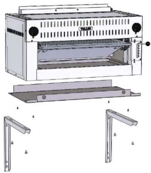
- Place the salamander into position on the brackets, making sure that the unit's bottom threaded attachment points are aligned with the holes in the brackets.(Fig. 6)
- Secure unit into position with 3/8" bolts at the bottom of the unit. Thread the bolts through the holes in the brackets and into the threaded attachment points on the bottom of the unit. (Fig. 6)
Radiant & Infrared Salamander shown on WALLMNT-CHRBKR Accessory

natural_image
Exterior view of a stainless steel industrial oven with control knobs and vented door (no visible text or symbols)Fig. 4
natural_image
Technical line drawing of a portable stove with open door, showing internal components and mounting brackets (no text or labels)Fig. 5
natural_image
Technical illustration of a portable kitchen machine with side and front views (no text or symbols)Fig. 6
Assembly over a Gas Range (Fig. 7)
If the broiler is to be mounted over a gas range, a reinforced shelf and special mounting brackets are required.
- Use Instructions from RSHELF Accessory kit to install reinforced shelf over a range.
- Using the four bolts provided, install mounting brackets on both top corners of reinforced shelf.
- Place and align broiler on top of brackets with the back of the unit flush with the rear of the shelf.
- Install 3/8-16 Bolts through underside of the RSHELF.
Radiant & Infrared Salamander shown on RSHELF Accessory

natural_image
Exterior view of a metal industrial machine labeled 'VULAN' (no additional text or symbols visible)Fig. 7
OPERATION
WARNING: THE BROILER AND ITS PARTS ARE HOT. BE CAREFUL WHEN OPERATING, CLEANING OR SERVICING THE BROILER.
CONTROLS
| Dual Zone Controls | — Controls cooking areas in the left and right hand side of the cavity allowing for flexibility and premium cooking performance. |
| Angled Handle | — elevates or lowers the broiling grid to different positions. Grasp the handle and pull towards broiler cavity. This releases the mechanism and allows the lifting handle to move into the desired position. |
| Burner Valve | — regulates the flow of gas to the burners. Gas flow is increased by turning the valve counterclockwise. |
| Drip Tray | — Collects grease and waste which is diverted by the tilt of the drip shield. DO NOT allow the drip tray to overflow. Empty the drip tray when three-quarters full to reduce the possibility of spillage. |
| Rack Handle | — glides the grid forward for easy loading and unloading. To operate, pull straight out. |
LIGHTING, RELIGHTING AND SHUTDOWN INSTRUCTIONS
- Turn burner valve to the OFF position and wait 5 minutes.
- Light the pilot adjacent to the main burner. Adjust the pilot valve screw until the pilot flame has a slight yellow tip. There are two pilots to light, on each end of the cooking chamber.
- After the pilot has been established, turn the burner valve to the ON position. The burner flames may be adjusted, using the air shutters located behind the manifold cover in the front of the range. There are no shutters on the IRB models.
- If the burners fail to light, turn off all valves, wait 5 minutes and repeat steps 1-3.
- To shut down, turn the burner valves to the OFF position.
RACK POSITION AND GAS SETTING
Each operator will find the optimum rack position and gas setting for various products; however, it is recommended that gas input be reduced first when lower rack temperatures are desired. Further reduction in rack temperatures, if necessary, can then be obtained by lowering rack position. Infrared Models must use the full gas setting. Max and minimum temperatures can be achieved at the following settings:
2 Burners On, rack at highest position, valves set to High - 800°F
1 Burner On, rack at lowest position, valves set to Low - 250°F
CLEANING
- Allow broiler to cool.
-
To remove broiler rack for cleaning, adjust broiler rack to center position.
-
Position left and right hands simultaneously on edges of broiler rack and raise both rack stops.
- Slide broiler rack and drip tray forward past rack stops, (which must be pivoted out of the way) holding tray up against racks.
- Remove broiler rack and drip tray from broiler.
- Let back of tray drop down to vertical to allow front hooks to disengage.
- Remove drip pan from broiler rack and clean as you would any normal utensil, using care not to damage the front hooks
- To replace, hook the drip tray to the broiler rack while tray is in a vertical position.
- Replace broiler rack and drip tray in side channels while holding tray up close to rack.
- Clean bottom pan. Slide pan out and wash with soap and water. Rinse thoroughly and wipe dry with a soft clean cloth.
- Clean stainless steel surfaces with a mild detergent and water, using a damp cloth, or with a commercial stainless steel cleaner. Rinse thoroughly and wipe dry with a soft clean cloth.
- Burner ports and throats should be thoroughly cleaned. Venturi must be free from grease and lint. DO NOT insert pick in burner port holes.
MAINTENANCE
WARNING: THE BROILER AND ITS PARTS ARE HOT. BE CAREFUL WHEN OPERATING, CLEANING OR SERVICING THE BROILER.
LUBRICATION
Burner valve stems must be lubricated. Upon sticking, a burner valve stem should receive maintenance from your local authorized servicer.
PILOT LIGHTS
Pilot lights are to be kept clean and adjusted at the proper flame height.
VENT
Annually, when the broiler is cool, check the flue and clear any obstructions.
SERVICE AND PARTS INFORMATION
Contact your local Service Agency to obtain service and parts information.
NOTES
PRINTED IN THE U.S.A.
PRINTED IN THE U.S.A.
CONDUIT D'EVACUATION
natural_image
3D rendering of a laboratory oven with ventilation grilles and control knobs (no visible text or symbols)natural_image
Exterior view of a white industrial machine with ventilation grilles and two protruding blades (no visible text or symbols)CONDUIT D.EVACUATION
natural_image
Close-up of a mechanical valve component with no visible text or symbols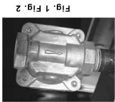
natural_image
Close-up of a mechanical component with no visible text or symbolsl'installation de la plombeire (Fiq. 3).
natural_image
Front view of a vintage kitchen appliance with ventilation grilles and control knobs (no visible text or symbols)36R/B/361RB
www.wolfequipment.com
C361RB
C36RB
MODELES

www.νulcanequipment.com
361RB
36R8
MODELES
UNITS


- INSTALLATION & OPERATION MANUAL FOR Salamander Broilers
- IMPORTANT FOR YOUR SAFETY
- IMPORTANT
- FOR YOUR SAFETY
- INSTALLATION, OPERATION AND CARE OF SALAMANDER BROILERS
- GENERAL
- INSTALLATION
- UNPACKING
- LOCATION
- INSTALLATION CODES AND STANDARDS
- In the United States of America:
- NOTE: In the Commonwealth of Massachusetts
- GAS CONNECTIONS
- GAS PRESSURE REGULATOR INSTALLATION
- FLUE CONNECTIONS
- ASSEMBLY
- Salamander Broiler Mounted on a Wall (Fig. 4).
- Assembly over a Gas Range (Fig. 7)
- OPERATION
- CONTROLS
- LIGHTING, RELIGHTING AND SHUTDOWN INSTRUCTIONS
- RACK POSITION AND GAS SETTING
- Burners On, rack at highest position, valves set to High - 800°F
- CLEANING
- MAINTENANCE
- LUBRICATION
- PILOT LIGHTS
- VENT
- SERVICE AND PARTS INFORMATION
- NOTES
- CONDUIT D'EVACUATION
Brand : Vulcan
Model : 36IRB
Category : Gril salamandre