
36ESB - Oven Vulcan - Free user manual and instructions
Find the device manual for free 36ESB Vulcan in PDF.

| Brand | Vulcan |
| Model | 36ESB |
| Product type | Professional electric oven |
| Width | 91.4 cm (36 inches) |
| Depth | 76.2 cm (30 inches) |
| Height | 91.4 cm (36 inches) |
| Weight | Approximately 150 kg |
| Power supply | 208/240 V, three-phase, 60 Hz |
| Power | 12 kW |
| Temperature range | 90 °C to 290 °C |
| Capacity | 4 rack levels |
| Main functions | Convection cooking, traditional cooking, browning, keep warm |
| Control type | Digital control with LED display |
| Cavity material | Stainless steel |
| Door | Insulating double glazing, heavy-duty hinges |
| Safety | Door lock during operation, emergency stop, thermal protection |
| Maintenance and cleaning | Dishwasher-safe removable racks, cavity to clean with a damp cloth, mild degreaser recommended |
| Spare parts and repairability | Available from Vulcan after-sales service (thermostat, heating elements, fan, door gaskets) |
| General information | Professional oven designed for intensive use in catering, guaranteed 2 years parts and labor |
Frequently Asked Questions - 36ESB Vulcan
User questions about 36ESB Vulcan
0 question about this device. Answer the ones you know or ask your own.
Ask a new question about this device
Download the instructions for your Oven in PDF format for free! Find your manual 36ESB - Vulcan and take your electronic device back in hand. On this page are published all the documents necessary for the use of your device. 36ESB by Vulcan.
USER MANUAL 36ESB Vulcan
INSTALLATION & OPERATION MANUAL FOR Salamander Broilers
ITW Food Equipment Group
VULCAN

MODELS
36ESB

www.vulcanhart.com
MODELS
C36ESB
www.wolfrange.com
36ESB

natural_image
Exterior view of a VULCAN industrial furnace or oven unit (no visible text or symbols on the device body)IMPORTANT FOR YOUR SAFETY
THIS MANUAL HAS BEEN PREPARED FOR PERSONNEL QUALIFIED TO INSTALL ELECTICAL EQUIPMENT, WHO SHOULD PERFORM THE INITIAL FIELD START-UP AND ADJUSTMENTS OF THE EQUIPMENT COVERED BY THIS MANUAL.
FOR YOUR SAFETY
DO NOT STORE OR USE GASOLINE OR OTHER FLAMMABLE VAPORS OR LIQUIDS IN THE VICINITY OF THIS OR ANY OTHER APPLIANCE.
WARNING: IMPROPER INSTALLATION, ADJUSTMENT, ALTERATION, SERVICE OR MAINTENANCE CAN CAUSE PROPERTY DAMAGE, INJURY OR DEATH. READ THE INSTALLATION, OPERATING AND MAINTENANCE INSTRUCTIONS THOROUGHLY BEFORE INSTALLING OR SERVICING THIS EQUIPMENT.
IN THE EVENT OF A POWER FAILURE, DO NOT ATTEMPT TO OPERATE THIS DEVICE.
INSTALLATION, OPERATION AND CARE OF ELECTRIC SALAMANANDER BROILERS
GENERAL
Your broiler is produced with quality workmanship and material. Proper installation, usage and maintenance of your broiler will result in many years of satisfactory performance.
The manufacturer suggests that you thoroughly read this entire manual and carefully follow all of the instructions provided.
INSTALLATION
UNPACKING
Immediately after unpacking, check for possible shipping damage. If the broiler is found to be damaged, save the packaging material and contact the carrier within 7 days of delivery.
Before installing, verify that the electrical service agrees with the specifications on the rating plate located under the crumb tray on the right side. If the supply and equipment requirements do not agree, contact your dealer or Hobart Food Equipment Group Canada immediately.
INSTALLATION CODES AND STANDARDS
Your Vulcan broiler must be installed in accordance with:
- State and local codes, or in the absence of local codes, with:
- National Electrical Code ANSI/NFPA-70 (latest edition).
In Canada refer to Canadian Electrical Code C22.1 Part 1 (latest edition).
LOCATION
The equipment area must be kept free and clear of combustible substances.
| Minimum Clearance | Combustible Construction | Non-Combustible Construction |
| Rear | 2" | 0" |
| Sides | 6" | 0" |
| Bottom | 4" with legs | 0" |
FORM F-47201 (06-14)
PRINTED IN THE U.S.A.
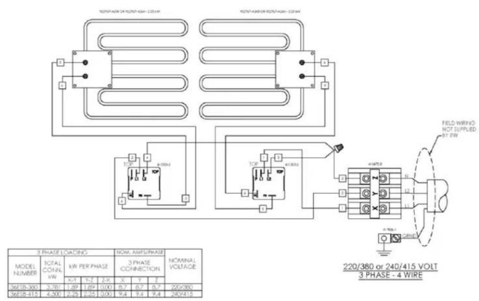
ELECTRICAL CONNECTIONS
WARNING: ELECTRICAL AND GROUNDING CONNECTIONS MUST COMPLY WITH THE APPLICABLE PORTIONS OF THE NATIONAL ELECTRICAL CODE AND/OR OTHER LOCAL ELECTRICAL CODES.
WARNING: DISCONNECT THE ELECTRICAL POWER SUPPLY AND PLACE A TAG AT THE DISCONNECT SWITCH TO INDICATE THAT YOU ARE WORKING ON THE CIRCUIT.
ESB36 Broiler
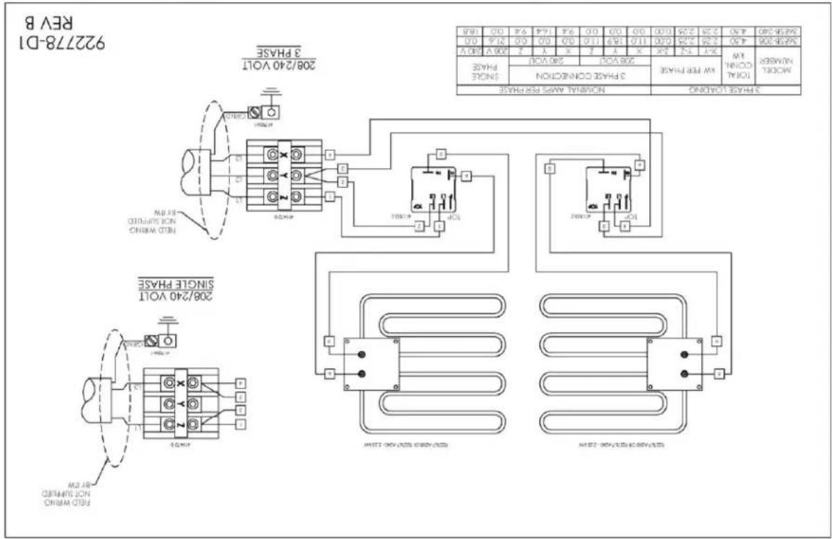
Bring the broiler leads down through the wire chase located on the rear of the range, and connect the terminal as required to the electrical supply. It may be necessary to remove the 14 -20 screw that retains the wire panel to the broiler in order to properly feed the wires through the rear. Refer to the wiring diagram of the broiler.
All required broiler wiring diagrams are packaged separately in a clear plastic bag and shipped with the broiler.
ASSEMBLY
Salamander Broiler Mounted on a Wall (Fig. 1).
The separate wall mounting bracket accessory (WALLMNT-CHRBKR) will be needed to wall mount the unit.
- Follow the combustible/noncombustible clearance guidelines that are listed in the "Installation" section in this manual.
- Make sure brackets are level and properly spaced so that bracket holes will align with the threaded holes on the bottom of the unit to be mounted. The short leg of the bracket with the holes that are nearest the elbow bend is to be placed against the wall. (Fig. 2)
- Secure brackets to wall by means of lag screws or bolts. (Fig. 2)
- Mount the brackets only in the upside-down "L" position as shown. (Fig. 2)
- Make sure the lag bolts or screws engage wall studs. Ensure that the wall construction is of the type that will support the salamander weight.
- Place the salamander into position on the brackets, making sure that the unit's bottom threaded attachment points are aligned with the holes in the brackets.(Fig. 3)
- Secure unit into position with 3/8" bolts at the bottom of the unit. Thread the bolts through the holes in the brackets and into the threaded attachment points on the bottom of the unit. (Fig. 3)
Electric Salamander shown on WALLMNT-CHRBKR Accessory
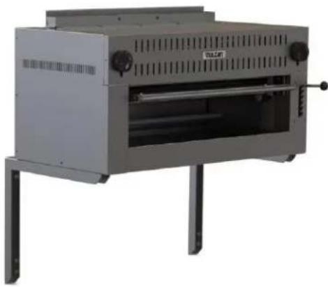
natural_image
Exterior view of a stainless steel industrial machine (no visible text or symbols)Fig. 1
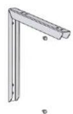
Fig. 2


natural_image
Technical illustration of a portable stove with internal grating and mounting brackets (no text or symbols)Fig. 3
Assembly over a Gas Range (Fig. 4)
If the broiler is to be mounted over a gas range, a reinforced shelf and special mounting brackets are required.
- Use Instructions from RSHELF Accessory kit to install reinforced shelf over a range.
- Using the four bolts provided, install mounting brackets on both top corners of reinforced shelf.
- Place and align broiler on top of brackets with the back of the unit flush with the rear of the shelf.
FORM F-47201 (06-14)
PRINTED IN THE U.S.A.
- Install 3/8-16 Bolts through underside of the RSHELF.
Electric Salamander shown on RSHELF Accessory
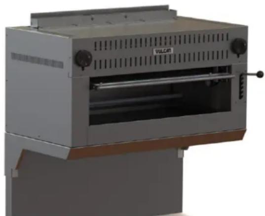
natural_image
3D rendering of a metallic industrial machine labeled 'VULCAN' with ventilation grilles and control knobs (no readable text beyond label)Fig. 4
OPERATION
WARNING: THE BROILER AND ITS PARTS ARE HOT. BE CAREFUL WHEN OPERATING, CLEANING OR SERVICING THE BROILER.
Controls (Fig. 5 & Fig. 6)
| Angled Handle | — Elevates or lowers the broiling grid to different positions. Grasp the handle and pull towards broiler cavity. This releases the mechanism and allows the lifting handle to move into the desired position. |
| Drip Tray | — Collects grease and waste which is diverted by the tilt of the drip shield. DO NOT allow the drip tray to overflow. Empty the drip tray when three-quarters full to reduce the possibility of spillage. |
| Rack Handle | — Glides the grid forward for easy loading and unloading. To operate, pull straight out. |
| Infinite Load Switches | — Two switches independently control the left and right heating elements in 208, 240, 220/380 and 240/415 volt models. Provides a variable range of on time from 22% to 100%. |
| 3-Heat, 4-Position Switch | — Controls both elements on 480 volt models. Provides approximately 100% of total available power (6 KW) at HI position, 50% at MED position, 25% at LO position, and 0% at OFF position. The left side element is slightly longer than the right side element and has a higher KW rating than the right side (3.150 vs. 2.850 KW). |
FORM F-47201 (06-14)
PRINTED IN THE U.S.A.
Infinite Load Switch

3-Heat, 4-Position Switch

natural_image
Technical line drawing of a mechanical component with no visible text or symbolsFig. 5 Fig. 6
To place 208/240 volt broilers into operation, turn the infinite switch knob to the desired setting.
To place 480 volt broilers into operation, turn the 3-heat, 4-position switch knob to the desired setting.
Wait 5 minutes for the broiler to preheat, than follow normal cooking procedures.
GRID ADJUSTMENT
Position the grid farther away from the burners for thick meats and for melting cheese or butter to avoid drying the product. Position the grid closer to the burners for bacon, toast and quick heating. Watch carefully to avoid burning.
LOADING AND UNLOADING
Pull rack out far enough to load product. Push rack back in place for cooking. Pull rack out for unloading.
POWER OUTAGE
If a power outage occurs, the broiler will automatically shut down. When power is restored, the broiler will automatically start heating.
FORM F-47201 (06-14)
PRINTED IN THE U.S.A.
If the broiler is left unattended during the power outage, turn either the infinite switch knob (220/380 & 208/240 volt) or the 3-heat, 4-position switch knob (480 volt) to the OFF position. When power is restored, turn control knob back to ON position. The broiler will be preheated in 5 minutes and normal cooking operation can then be resumed.
CARE AND CLEANING
- Allow broiler to cool.
- To remove broiler rack for cleaning, raise broiler to center position.
- Position left and right hands simultaneously on edges of broiler rack and raise both rack stops.
- Slide broiler rack and drip tray forward past rack stops, holding tray up against racks.
- Remove broiler rack and drip tray from broiler.
- Let back of tray drop down to vertical to allow front hooks to disengage.
- Remove drip pan from broiler rack and clean as you would any normal utensil.
- To replace, hook the drip tray to the broiler rack while tray is in a vertical position.
- Replace broiler rack and drip tray in side channels while holding tray up close to rack.
- Clean bottom pan. Slide pan out and wash with soap and water. Rinse thoroughly and wipe dry with a soft clean cloth.
- Clean stainless steel surfaces using a damp cloth or with a commercial stainless steel cleaner.
MAINTENANCE
WARNING: THE BROILER AND ITS PARTS ARE HOT. BE CAREFUL WHEN OPERATING, CLEANING OR SERVICING THE BROILER.

Disconnect power supply and follow lockout/tagout procedures and servicing the appliance.
VENT
Annually, when the broiler is cool, check the flue and clear any obstructions.
SERVICE AND PARTS INFORMATION
Contact your local Service Agency to obtain service and parts information.
FORM F-47201 (06-14)
PRINTED IN THE U.S.A.


922778-D3
REV B
NOTES
92278-03 REV B

922778-D2 REV B
| SALADY | 2017 | 2018 | 2019 | 2020 | 2021 | 2022 |
| BAYA | X | X | X | X | X | X |
| CAYA | BAYA | BYA | BYA | BYA | ||
| STANDY | NONCINNCO | NONCINNCO | ||||
| BYA | BYA | BYA | CINNCO | BYA | BYA | |

natural_image
Technical line drawing of a mechanical component with labeled parts (NO1, ON) and no readable text or symbols beyond labelsnatural_image
3D rendering of a white industrial oven with ventilation grilles and control knobs (no visible text or symbols)natural_image
Exterior view of a gray industrial machine with ventilation grilles and two upright towers (no visible text or symbols)Non-Combustible Construction
Comustible Construction
Minimum Clearance
combustible.
natural_image
Exterior view of a metallic industrial enclosure with ventilation grilles and mounting feet (no visible text or symbols)36E5B
WW.wolfrangee.com
C36E5B
MODELS
ww.vulcanhart.com

36E5B
MODELS
sn
R

UNITS

- INSTALLATION & OPERATION MANUAL FOR Salamander Broilers
- IMPORTANT FOR YOUR SAFETY
- FOR YOUR SAFETY
- INSTALLATION, OPERATION AND CARE OF ELECTRIC SALAMANANDER BROILERS
- GENERAL
- INSTALLATION
- UNPACKING
- INSTALLATION CODES AND STANDARDS
- LOCATION
- ELECTRICAL CONNECTIONS
- ESB36 Broiler
- ASSEMBLY
- Salamander Broiler Mounted on a Wall (Fig. 1).
- Electric Salamander shown on WALLMNT-CHRBKR Accessory
- Assembly over a Gas Range (Fig. 4)
- OPERATION
- GRID ADJUSTMENT
- LOADING AND UNLOADING
- POWER OUTAGE
- CARE AND CLEANING
- MAINTENANCE
- VENT
- SERVICE AND PARTS INFORMATION
- NOTES
Brand : Vulcan
Model : 36ESB
Category : Oven