SRC-64 - Uncategorized Appsys ProAudio - Free user manual and instructions
Find the device manual for free SRC-64 Appsys ProAudio in PDF.

| Product Type | Digital Audio Sample Rate Converter |
| Brand | Appsys ProAudio |
| Model | SRC-64 |
| Dimensions (W x H x D) | Approximately 220 x 44 x 160 mm (1/2 rack width, 1U height) |
| Weight | Approximately 0.8 kg |
| Power Supply | External 12V DC power adapter (center positive) |
| Power Consumption | Approximately 5W |
| Input Connectors | AES/EBU (XLR) and S/PDIF (RCA coaxial) |
| Output Connectors | AES/EBU (XLR) and S/PDIF (RCA coaxial) |
| Supported Sample Rates | 32 kHz to 192 kHz (input and output) |
| Sample Rate Conversion Ratio | Any input to any output within range |
| Bit Depth | Up to 24-bit |
| Main Functions | Sample rate conversion between different digital audio formats; jitter reduction; signal reclocking |
| Indicators | Power LED, Lock LED, Sample rate LEDs for input and output |
| Controls | Power switch, input select button, output sample rate selector |
| Housing Material | Aluminum chassis with steel top cover |
| Operating Temperature | 0°C to 40°C |
| Storage Temperature | -20°C to 60°C |
| Humidity (non-condensing) | Up to 80% |
| Maintenance and Cleaning | Use a dry, soft cloth to clean the exterior. Do not use solvents or abrasive cleaners. Ensure unit is powered off and disconnected from power before cleaning. |
| Safety Precautions | Use only the supplied power adapter. Do not expose to moisture or liquid. Avoid placing near heat sources. Ensure adequate ventilation. |
| Spare Parts and Repairability | Contact Appsys ProAudio or authorized service centers for replacement parts. The device should be serviced by qualified personnel only. |
| General Information | The SRC-64 is a professional-grade sample rate converter designed for studio and live sound applications. It features dual inputs and outputs, allowing flexible routing and format conversion. |
Frequently Asked Questions - SRC-64 Appsys ProAudio
User questions about SRC-64 Appsys ProAudio
0 question about this device. Answer the ones you know or ask your own.
Ask a new question about this device
Download the instructions for your Uncategorized in PDF format for free! Find your manual SRC-64 - Appsys ProAudio and take your electronic device back in hand. On this page are published all the documents necessary for the use of your device. SRC-64 by Appsys ProAudio.
USER MANUAL SRC-64 Appsys ProAudio
natural_image
3D rendering of a green printed circuit board with various integrated circuits and connectors (no visible text or symbols)SRC·64
Asynchronous Sample Rate Converter
Add-on Module for MVR-64
User's Manual
((en))
Table of Contents
1. GENERAL....3
1.1 Features 3
1.2. Box Contents 4
1.3. Conventions used in this manual 4
2. INSTALLATION 5
2.1. Multiverter Firmware Check 5
2.2. Hardware Installation 6
3. OPERATION 8
3.1. General 8
3.2. Select the async input....8
3.3. Select the async output....9
3.4. Select the async clock source 10
3.5.ASRC Status Display 10
4. CONFIGURATION EXAMPLES 12
4.1. Typical Setups 12
5. MAINTENANCE 14
5.1.ASRC selfiest 14
5.2. Determining ASRC Firmware|Hardware version 14
5.3.ASRC Firmware Upgrade 14
6. SPECIFICATIONS....16
7. APPENDIX 17
7.1. Warranty 17
7.2. Manufacturer contact 17
7.3. Recycling 17
7.4. Document Revision History 17
7.5 About this document....17
1. GENERAL
1.1 Features
The SRC-64 add-on module adds the capability of asynchronous sample rate conversion to your multiverter. Designed as internal add-on module, it leaves the "Extension" port available to other break-out boxes.
(Note: The module is called "ASRC" in this manual for clarity).
It features highest analog performance |THD+N-134dB typ.1, 64-channel, bi-directional conversion between any interfaces supported by the multiverter plus a number of special modes for maximum flexibility.
The ASRC can be assigned to any input interface and also any output of the multiverter, giving a true bi-directional conversion between both clock domains:

flowchart
graph LR
    A["Async Inputs"] --> B["ASRC In"]
    B --> C["Multiverter Routing Matrix Core"]
    C --> D["ASRC Out"]
    D --> E["Async Outputs"]
    F["Sync Inputs"] --> C
    G["Sync Outputs"] --> C
    style C fill:#000,stroke:#fff,color:#fff
    note right of C: "Asynchronous clock path"
    note right of E: "Async Outputs"

Asynchronous clock domain („Async clock“). Clock can be taken from async input, or BNC, or generated internally.

Main clock domain. Clock is taken from selected multiverter clock source
■The ASRC is inserted (by software) between the selected input and the rest of the multiverter. The input can run independently, and the ASRC takes care of matching the data to the main clock of the multiverter.
■For the output, the ASRC can be inserted between the main clock of the multiverter and the selected output. The data is then converted to match the ASRC's asynchronous clock ("async clock") and sample rate before it is sent out.
■ Existing multiverter routing capabilities are fully preserved.
■Special modes allow the use of two MADl or AES50 ports together, to send and receive all 64 channels at 96 kHz (48ch for AES50). Conversions between MADl 64ch @96k => MADl 64ch @48k or vice versa - using two MADl ports for the 96k part and one for the 48k part - are also supported.
1.2. Box Contents
■1 SRC-64 PCB Module
■2 Screws M3×20 T10
■2 Spacers
■This manual
1.3. Conventions used in this manual
■A button on the front of the device is shown like this: Sel
■The encoder can be pushed. This is shown as 0K
■ A particular LED on the front of the device is shown like this: ✦ WCLK
■ Text indicated on the seven-segment display is shown as 02

A section marked with a warning sign mark tells you that the information is particularly important to avoid damage or malfunction.

Filled circles with an exclamation mark indicates an action that must be performed | "Required"

A section marked with a prohibited sign tells you that the action indicated is prohibited ("Prohibited")

A section marked with a "information" icon indicates a useful tip.
2. INSTALLATION
2.1. Multiverter Firmware Check

The multiverter requires at least firmware 2.0 for the SRC to work.
Please check and update if required |see below|.
■ Check the multiverters' firmware version: Press Recall move to Function press OK move to 12 press OK move to AD
■ If the seven-segment display shows 02 or higher, your firmware is already capable of addressing the ASRC, and you can proceed with the next section [2.2 Hardware Installation].
If 01 is shown, a firmware update is required. Download the firmware update from our website and follow the instructions in the README.TXT file contained in the package.
2.2. Hardware Installation

CAUTION: To prevent electric shock, remove all mains power plugs from the multiverter before opening!

ATTENTION: Static Sensitive Devices Observe Precautions for Handling!
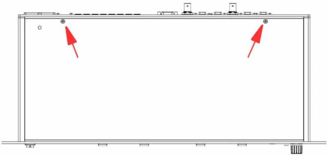
■Remove the two screws at the rear of the multiverter's top cover |Torx T10):
natural_image
Pure architectural floor plan lines without any text, numbers, or symbols■Flip the multiverte to detach the top cover. Disconnect the cover's ground connection at the base.
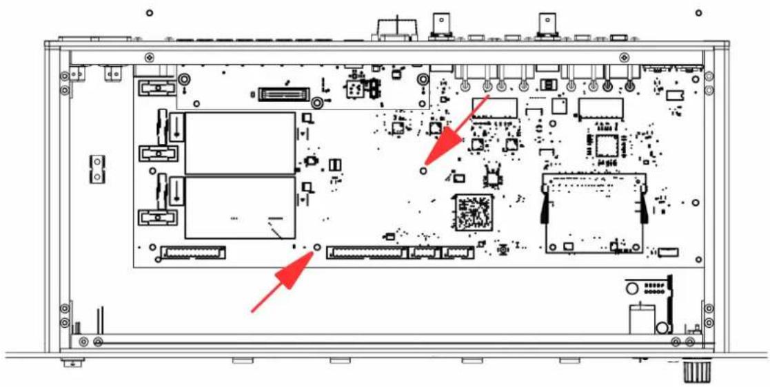
■Remove the indicated two screws from the multiverters main board:
natural_image
Technical diagram of an internal electronic device with labeled ports and connectors (no readable text or symbols)■Place the supplied spacers on top of the holes, and carefully plug the ASRC into the main board.
■Insert the supplied screws through the ASRC holes and the spacers, then fasten them.
■Re-connect the covers ground connection to the base.
■Slide the top cover into the front panel slit, then close the lid and mount the cover using the two black screws.
3. OPERATION
3.1. General
The ASRC is configured and enabled disabled through the "Clock" menu in a few simple steps, described below.
The general sequence is:
1) Select the async input
2) Select the async output
3| Select the async clock (the clock source for async input+output)
4) Configure the routing matrix (same as without ASRC)
You can always go back to the previous step by pushing the Back button.

See chapter "4. Configuration Examples" for typical setups
3.2. Select the async input
This selects the input interface whose data is received at its own asynchronous clock and sample rate, and is then converted to the multiverter's main clock and sample rate.
■Push the Set button in the "Clock" menu.
■ Navigate the cursor to the ASRC LED and push OK to confirm. The seven-segment display shows in to indicate the input selection mode.
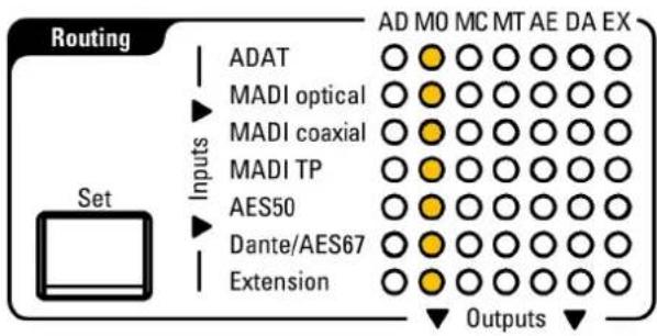
■You can now select the appropriate input rows). The example shows how to select "MAD|optical" as asynchronous input:

text_image
Routing ADAT MADI optical MADI coaxial MADI TP AES50 Dante/AES67 Extension AD MO MC MT AE DA EX Inputs Set OutputsNote: For some configurations it is possible to select two rows at once. This is used if you want to concatenate the channels from two inputs to make use of all
64 channels at 96kHz (48ch with AES50), or 32ch at 192kHz.
■When ready, push OK to confirm.

If you need only asynchronous outputs, select "X" for the inputs. This disables the receive part of the ASRC, and all inputs run now on the main clock.
3.3. Select the async output
This selects the output interface whose data is converted from the multiverter's main clock sample rate to the async clock on output.

Some interfaces (AES50, Dante|AES67) do not allow different receive and transmit clocks. When such an interface is selected as input, the output runs automatically at the same clock and cannot be chosen separately.
■Assign the input as described. When this is finished, the seven-segment display shows 0u to indicate the output selection mode.
■Select the appropriate output column[s]. The example shows how to select 'MADl optical' as asynchronous output:
text_image
Routing ADAT MADI optical MADI coaxial MADI TP AES50 Dante/AES67 Extension AD MO MC MT AE DA EX Inputs Set Outputs■ Note: For some configurations it is possible to select two rows at once. This is used if you want to concatenate two outputs together to make use of all 64 channels at 96 kHz |48ch with AES50|, or 32ch at 192 kHz. Selecting "X" disables the ASRC for the output direction.

If you need only asynchronous inputs, select "X" for the outputs. Transmitted data is then output at the multiverter's main clock sampling rate (no samplerate conversion happens for transmit data).
If no async input and no async output is selected [both "X"], the ASRC function is disabled and the ASRC is turned off.
3.4. Select the async clock source
This selects the source for the asynchronous clock (the clock which is used for the selected async inputs and outputs).
Depending on the async interfaces selected, not all interfaces can be used as source for the async clock. Usually, it's possible to select a | the async input as clock source, b | the BNC wordclock input, or c) an internally generated clock.
■ The seven-segment display shows RS to indicate the "async" clock selection mode, and the *ASRC LED shows yellow.
■ Navigate the cursor to the desired clock source and push OK to confirm.
■Depending on the clock source, the multiverter may ask you now to choose the SMUX mode{how single-speed data should be interpreted} or the samplerate (if you are using an internal clock). Push OK to confirm.
3.5. ASRC Status Display
The status LEDs for "Routing", "Clock" and "Monitor" show yellow instead of green to indicate that the respective function makes use of the ASRC.
■ When the ASRC is active, the ✉ASRC LED is lit.
Yellow color indicates that the selected input clock is valid, while red color indicates that the input clock is missing or invalid.
■The ASRC clock source and samplerate are shown in yellow if the clock is valid, otherwise in red.
In the routing matrix, connections using the ASRC are displayed yellow in contrast to the normal green when the selected conversion involves the use of the ASRC. If there is any condition which prevents the data from being converted (i.e. missing input data or clock) the respective connection is shown in red.
In the "Monitor" section, the selected input is displayed in yellow (in contrast to the normal green) when the selected input runs through the ASRC.
4. CONFIGURATION EXAMPLES
The examples below show typical conversion setups with their configuration of the ASRC inputs, outputs, possible async clock sources and typical routings.

Although the "Routing" matrix examples show only conversions involving the ASRC, more conversions can run at the same time:
■An arbitrary number of additional conversions within the main clock domain can run in parallel.
■Any ASRCed input can additionally be routed to an arbitrary number of outputs in the main clock domain.
4.1. Typical Setups
| Setup<=> bidirectional=> unidirectional | Step 1:ASRC input'Which input comesasync and should go through the ASRC?' | Step 2:ASRC output'Which output should run at the ASRC samplerate?' | Step 3:ASRC clock source'From where should the ASRC take its clock?' | Step 4:Routing'Which input should go to which output?'You can add additional routings as required! | |||||||||||||||||||||||||||||
| AES50 48ch/96kHz<=>Dante 48ch/48kHzUse 'MT' port in AES50 mode, see multiverter Manual | AD | MO | MC | MT | AE | DA | EX | AD | MO | MC | MT | AE | DA | EX | AEMTWCLKINT | AD | MO | MC | MT | AE | DA | EX | |||||||||||
| AD | AD | O | O | AD | AD | ||||||||||||||||||||||||||||
| MO | MO | O | O | MO | MO | ||||||||||||||||||||||||||||
| MC | MC | O | O | MC | MC | ||||||||||||||||||||||||||||
| MT | O | O | O | O | O | O | O | MT | O | O | MT | MT | O | ||||||||||||||||||||
| AE | O | O | O | O | O | O | O | AE | O | O | AE | AE | O | ||||||||||||||||||||
| DA | DA | O | O | DA | O | O | DA | O | O | ||||||||||||||||||||||||
| EX | EX | O | O | EX | EX | ||||||||||||||||||||||||||||
| MAD|optical32ch/96kHz<=>Dante 32ch/48kHz | AD | MO | MC | MT | AE | DA | EX | AD | MO | MC | MT | AE | DA | EX | MOWCLKINT | AD | MO | MC | MT | AE | DA | EX | |||||||||||
| AD | AD | O | AD | AD | |||||||||||||||||||||||||||||
| MO | O | O | O | O | O | O | O | MO | O | MO | MO | O | |||||||||||||||||||||
| MC | MC | O | MC | MC | |||||||||||||||||||||||||||||
| MT | MT | O | MT | MT | |||||||||||||||||||||||||||||
| AE | AE | O | AE | AE | |||||||||||||||||||||||||||||
| DA | DA | O | DA | O | DA | O | O | ||||||||||||||||||||||||||
| EX | EX | O | EX | EX | |||||||||||||||||||||||||||||
| MAD|optical+MAD| coaxial64ch/96kHz<=>Dante 64ch/48kHz | AD | MO | MC | MT | AE | DA | EX | AD | MO | MC | MT | AE | DA | EX | MOMCWCLKINT | AD | MO | MC | MT | AE | DA | EX | |||||||||||
| AD | AD | O | O | AD | AD | ||||||||||||||||||||||||||||
| MO | O | O | O | O | O | O | O | MO | O | O | MO | MO | O | ||||||||||||||||||||
| MC | O | O | O | O | O | O | O | MC | O | O | MC | MC | O | ||||||||||||||||||||
| MT | MT | O | O | MT | MT | ||||||||||||||||||||||||||||
| AE | AE | O | O | AE | AE | ||||||||||||||||||||||||||||
| DA | DA | O | O | DA | O | O | DA | O | O | ||||||||||||||||||||||||
| EX | EX | O | O | EX | EX | ||||||||||||||||||||||||||||
| MAD|optical+MAD|coaxial64ch/96kHz=>MAD|optical64ch/48kHz | AD | MO | MC | MT | AE | DA | EX | AD | MO | MC | MT | AE | DA | EX | MO | MC | WCLKINT | AD | MO | MC | MT | AE | DA | EX | ||||||
| AD | AD | MO | AD | |||||||||||||||||||||||||||
| MO | O | O | O | O | O | O | O | MO | O | O | MC | O | MO | O | ||||||||||||||||
| MC | O | O | O | O | O | O | O | MC | O | O | MT | O | MC | O | ||||||||||||||||
| MT | AE | O | O | AE | O | MT | ||||||||||||||||||||||||
| AE | DA | O | O | DA | AE | |||||||||||||||||||||||||
| DA | EX | EX | DA | |||||||||||||||||||||||||||
| EX | EX | |||||||||||||||||||||||||||||
| MAD|optical64ch/48kHz=>MAD|optical+MAD|coaxial64ch/96kHz | AD | MO | MC | MT | AE | DA | EX | AD | MO | MC | MT | AE | DA | EX | MO | WCLKINT | AD | MO | MC | MT | AE | DA | EX | |||||||
| AD | AD | O | O | MO | AD | |||||||||||||||||||||||||
| MO | O | O | MO | O | O | MC | MO | O | O | |||||||||||||||||||||
| MC | O | O | MC | O | O | MT | MC | |||||||||||||||||||||||
| MT | O | MT | O | O | AE | O | MT | |||||||||||||||||||||||
| AE | O | O | AE | O | O | DA | AE | |||||||||||||||||||||||
| DA | O | O | DA | O | O | EX | O | DA | ||||||||||||||||||||||
| EX | EX | O | O | EX | ||||||||||||||||||||||||||
| MAD|opticalat any samplerate=>anything else*at main samplerate*|All outputs shown | AD | MO | MC | MT | AE | DA | EX | AD | MO | MC | MT | AE | DA | EX | MO | WCLK | AD | MO | MC | MT | AE | DA | EX | |||||||
| AD | AD | MO | AD | |||||||||||||||||||||||||||
| MO | O | O | O | O | O | O | O | MO | O | O | MC | O | MO | O | O | O | O | O | ||||||||||||
| MC | MC | O | O | MT | O | MC | ||||||||||||||||||||||||
| MT | MT | O | AE | O | MT | |||||||||||||||||||||||||
| AE | AE | O | O | DA | AE | |||||||||||||||||||||||||
| DA | DA | O | O | EX | DA | |||||||||||||||||||||||||
| EX | EX | EX | ||||||||||||||||||||||||||||
| Any input*at main samplerate=>Dante48kHz*|ADAT shown | AD | MO | MC | MT | AE | DA | EX | AD | MO | MC | MT | AE | DA | EX | DA | INT | AD | MO | MC | MT | AE | DA | EX | |||||||
| AD | AD | O | MO | AD | O | |||||||||||||||||||||||||
| MO | MO | O | MC | MO | ||||||||||||||||||||||||||
| MC | MC | O | MT | MO | ||||||||||||||||||||||||||
| MT | MT | O | AE | MT | ||||||||||||||||||||||||||
| AE | AE | O | DA | AE | ||||||||||||||||||||||||||
| DA | O | O | O | O | O | O | O | DA | O | EX | DA | |||||||||||||||||||
| EX | EX | O | EX | |||||||||||||||||||||||||||
| Any input*at main samplerate=>MAD|optical48kHz*|ADAT shown | AD | MO | MC | MT | AE | DA | EX | AD | MO | MC | MT | AE | DA | EX | WCLKINT | AD | MO | MC | MT | AE | DA | EX | ||||||||
| AD | AD | O | MO | AD | O | |||||||||||||||||||||||||
| MO | O | O | MO | O | MC | MO | ||||||||||||||||||||||||
| MC | O | O | MC | O | MT | MO | ||||||||||||||||||||||||
| MT | O | MT | O | AE | O | MT | ||||||||||||||||||||||||
| AE | O | O | AE | O | DA | AE | ||||||||||||||||||||||||
| DA | O | O | DA | O | EX | O | DA | |||||||||||||||||||||||
| EX | EX | O | EX | |||||||||||||||||||||||||||
| ASRC disabled | AD | MO | MC | MT | AE | DA | EX | AD | MO | MC | MT | AE | DA | EX | any any | |||||||||||||||
| AD | AD | MO | ||||||||||||||||||||||||||||
| MO | O | O | MO | O | O | MC | ||||||||||||||||||||||||
| MC | O | O | MC | O | O | MT | ||||||||||||||||||||||||
| MT | O | MT | O | AE | ||||||||||||||||||||||||||
| AE | O | O | AE | O | O | DA | ||||||||||||||||||||||||
| DA | O | O | DA | O | O | EX | ||||||||||||||||||||||||
| EX | EX | O | ||||||||||||||||||||||||||||
5. MAINTENANCE
5.1.ASRC selftest
If there is any doubt on the correct operation of the ASRC, it can easily be checked by running the ASRC selftest. The selftest works by passing an internally generated sine wave forward and back through the ASRC (running two conversions, from 96 kHz => 88.2 kHz => 96 kHz) on all 64 channels.
■ To enter ASRC selftest mode: Press Recall move to Function move to 11 press OK turn the encoder until the seven-segment display shows 'ASRC selftest' and press OK.
■The resulting data is output on the headphones where it can be verified by listening to it. The ASRC works correctly if a clean, non-distorted 1000Hz sine tone can be heard on all channels. Use *Ch to listen to the appropriate channel. The output volume can be adjusted using *Vol.
■The resulting data is also output on MAD optical channels 1-32 and MAD coaxial channels 33-64 as two 96kHz/32ch streams, clocked by the internal clock of the multiverter. You can use any signal meter to check the result; the output level should be -20dB on all channels.
■ To exit ASRC selftest mode, press the Back button.
5.2. Determining ASRC Firmware/Hardware version
To check the firmware and hardware version of the ASRC module: Press Recall move to Function press OK move to 12 press OK
■Move the cursor to - ✱ EX to show the ASRC Firmware Major Version number - ✱ Ch to show the ASRC Firmware Minor Version number - ✱ Vol to show the ASRC Hardware Version in the seven-segment display.
5.3. ASRC Firmware Upgrade
Although seldom required, the ASRC firmware itself can be upgraded. This is done similar to the multiverter upgrade, with the difference that the USB plug has to be connected directly to the ASRC (not on the multiverter).

RISK OF ELECTRIC SHOCK:
It is strongly advised to power the Multiverter from the DC source
(9..24V) during upgrade.
When powering via AC mains, it is possible to touch live parts inside during the upgrade! Only qualified personnel should do this, obeying the safety rules when working with live mains voltage.
■The ASRC module must be mounted within the multiverter during update (the multiverter supplies power to it).
■The cover of the multiverter must remain open throughout the upgrade process to allow plugging of the USB cable into the ASRC's USB jack.
■Follow the instructions in the README.TXT file of the firmware update.
- SPECIFICATIONS
| Parameter Value | ||||||
| Dimensions 115x94x2 | 7 mm | BxHxD | |||||
| Weight 65 g | ||||||
| Operating temperature | 0..+70°C, non-condensing | |||||
| Storage temperature | 40..+85°C, non-condensing | |||||
| Power consumption 7 | W max. | |||||
| Channel count Up to 6 | 4 per direction in x1 modes {44.1 / 48 kHz} | |||||
| Up to 64 per interface in x2 modes {88.2 / 96 kHz} | ||||||
| Up to 32 per interface in x4 modes {176.4 / 192 kHz} | ||||||
| Sample rates Arbitrary | sample rates between 32kHz and 192kHz | |||||
| Analog performance T | HD+N..-133 dB typ., -120dB max.Dynamic range [A-weighted, 20 Hz to 20 kHz]: 139 dB | |||||
| Latency For up-sampling conversions: tls = 16ifs_in + 32ifs_in | ||||||
| fs_in / kHz t / ms | ||||||
| 44.1 | 1.09 | |||||
| 48 | 1.03 | |||||
| 88.2 | 0.54 | |||||
| 96 | 0.5 | |||||
| 176.2 | 0.27 | |||||
| For down-sampling conversions: tls = 16ifs_in + |32ifs_in|*(ifs_inifs_out) | ||||||
| fs_in / kHz | fs_out / kHz | t / ms | 176.4 | fs_in / kHz | is_out / kHz | |
| 48 | 44.1 1.06 | 44.1 0.82 | ||||
| 88.2 | 44.1 0.91 | 48 | 0.76 | |||
| 48 | 0.84 | 96 | 88.2 0.45 | |||
| 96 | 44.1 0.89 | 192 44.1 48 | 0.81 | |||
| 48 | 0.83 | 0.75 | ||||
| 88.2 0.53 | 88.2 0.45 | |||||
| 96 | ||||||
| 176.4 | ||||||
7. APPENDIX
7.1. Warranty
We offer a full two (2) year warranty from the date of purchase. Within this period, we repair or exchange your device free of charge in case of any defect*. If you experience any problems, please contact us first. We try hard to solve your problem as soon as possible, even after the warranty period.
* Not covered by the warranty are any damages resulting out of improper use, willful damage, normal wear-out (especially of the connectors) or connection with incompatible devices.
7.2. Manufacturer contact
Appsys ProAudio
Rolf Eichenseher
Bullingerstr. 63 / BK241
CH-8004 Zürich
Switzerland
www.appsys.ch
info @appsys.ch
Phone: +41 43 537 28 51
Mobile: +41 76 747 07 42
7.3. Recycling

According to EU directive 2002/96/EU, electronic devices with a crossed-out dustbin may not be disposed into normal domestic waste.
Please return the products back for environment-friendly recycling, we'll refund you the shipping fees.
7.4. Document Revision History
2: Layout improved
1: Initial release
7.5. About this document
All trademarks mentioned in this document are property of the respective owners. All information provided here is subject to change without prior notice.
Copyright © 2017-2018 Appsys ProAudio · Printed in Switzerland