
MVR-64 - Audio/video converter Appsys ProAudio - Free user manual and instructions
Find the device manual for free MVR-64 Appsys ProAudio in PDF.


User questions about MVR-64 Appsys ProAudio
0 question about this device. Answer the ones you know or ask your own.
Ask a new question about this device
Download the instructions for your Audio/video converter in PDF format for free! Find your manual MVR-64 - Appsys ProAudio and take your electronic device back in hand. On this page are published all the documents necessary for the use of your device. MVR-64 by Appsys ProAudio.
USER MANUAL MVR-64 Appsys ProAudio
Multiverter
Digital Format Converter
MVR·64
User's Manual
((en))
Table of Contents
1. GENERAL 4
1.1. Conventions used in this manual 4
1.2. Safety precautions 5
1.3. Foreword 5
1.4. Box Contents 5
2. INTRODUCTION 6
2.1. Front panel 6
2.2. Rear panel 6
2.3. Overview....7
2.4.User interface 7
3. CONNECTIONS OVERVIEW 12
3.1. AC Power 12
3.2. DC Power 12
3.3. ADAT/SPD/F/AES3 optical 12
3.4. PC|USB 13
3.5. RS485 13
3.6. Extension 14
3.7.MADl optical 14
3.8. MAD | BNC 15
3.9. MAD|TP 15
3.10. AES50 15
3.11. Word clock 16
3.12. Dantei AES 67 16
3.13. MID 17
3.14. Control data forwarding 17
4. PRESETS 19
4.1. Preset Recall 19
4.2. Preset Store 20
4.3. Changed presets 20
4.4. Auto-Store 21
5. ROUTING 22
6. CLOCKING 26
6.1. ClockShield 26
6.2. Clock source selection 27
6.3. Dante Clock....29
7. PANEL LOCK 30
8. MONITOR 31
9. ADVANCED TOPICS 33
9.1.Testione mode 33
9.2. Configuration settings 33
9.3. Audio Interface self-test 37
9.4. LED and button test 38
9.5. ASRC self-test 39
- FIRMWARE 40
10.1. Version check 40
10.2. Upgrade 41
- COMMAND LINE REFERENCE 42
- SPECIFICATIONS 43
- ACCESSORIES 45
13.1. AES50|MADI-TP Pinswap adapter cable 45
13.2. MTA-64 Adapter for MADl-TP 45
13.3. SRC-64 Asynchronous Samplerate Converter Module [optional hardware]....46
13.4. Break-out boxes 47
- APPENDIX 48
14.1.Warranty 48
14.2. Manufacturer contact 48
14.3. FCC Compliance 48
14.4. Recycling 49
14.5. About this document....49
1. GENERAL
1.1. Conventions used in this manual
■A button on the front of the device is shown like this: Set
■ A particular LED on the front of the device is shown like this: ✦ WCLK
■ Text indicated on the seven-segment display is shown as 02
■Operations in a particular control method are indicated by a triangle:
▶ Front panel, ▶ Web or ▶ Command line

A section marked with a warning sign mark tells you that the information is particularly important to avoid damage or malfunction.

Filled circles with an exclamation mark indicates an action that must be performed | "Required" |

A section marked with a prohibited sign tells you that the action indicated is prohibited ("Prohibited")

A section marked with a "information" icon indicates a useful tip.
1.2. Safety precautions

This device is intended to be used in a professional environment with restricted access only.
1.3. Foreword
Thank you for purchasing one of the most innovative digital audio converters on the market. The multiverter was designed with true vendor independence and interoperability in mind, with the idea to make all your gear interact seamlessly.
Please note that due to the complex nature of such a product we decided to introduce functionality step-by-step, so you will find some functions described in this manual marked "available as firmware update". We will continue to supply firmware updates to continuously improve the functionality of the device.
Please don't hesitate to tell us your feedback, thoughts and ideas, we try hard to make the multiverter your most valuable tool!
1.4. Box Contents
■MVR-64 multiverter device
■AC power cord (country specific)
■This manual
2. INTRODUCTION
2.1. Front panel

2.2. Rear panel

2.3. Overview
The multiverter is a unique device which allows you to convert digital audio data in any direction between the most popular formats: ADAT, MADl optical, MADl coaxial, MADl-TP, AES50, Dante and others | via break-out boxes|.
All inputs can freely be routed to all of the outputs, with an arbitrary number of splits and merges supported at the same time.
Channel-wise routing between different interfaces is supported via the remote control via integrated web server, or via command line.
The routing matrix supports 448x448 channels (7x7 interfaces with 64ch each) at single speed modes, 224x224 channels at double-speed and 112x112 channels at quad-speed modes.
Using the optional SRC-64 Asynchronous Samplerate Converter Module (optional hardware), asynchronous samplerate conversion on 64x64 bi-directional channels, up to 192kHz is supported.
The device is prepared for headamp remote control | Yamaha, Behringer, M|DAS|.
Diagnostics are made simple by an integrated headphones amplifier and a test tone generator. Three power inlets allow operation from either AC or DC (battery pack) with full redundancy.
2.4. User interface
The device has been designed for fast and simple operation, with a no-frills everything-at-a glance concept. The unit can be operated either
directly on the front panel
via the integrated web server
via command line▶{telnet or USB}
via M|D| ▶|Preset recall only|
In this manual, the required steps for each operation mode are indicated by
▶ Front panel, ▶ Web and ▶ Command line headers.
All operation modes can be used simultaneously, and any status change is immediately reflected on all interfaces. For example, it's possible to make some routing connections on the front panel, and later change them via the web interface or the command line.
▶Front panel
Most settings are directly accessible without the need to walk through lengthy menus:
■ To change a setting, first push the appropriate rectangular button (e.g. Set). You have now entered "Menu" mode, indicated by a yellow blinking cursor.
■Move the cursor by turning the encoder (rotary knob) left or right to move it to the desired setting.
■When the cursor is at the beginning or end of the column or line, continue turning to make it wrap around.
■Push the encoder knob (or push the appropriate menu button again) to confirm your changes. To return to the previous state without making any changes, push the ▶Back button.
■When the device is normal operation (i.e. not within a menu), turning the encoder knob changes "Volume" or "Channel" of the monitor headphones, while pushing the encoder toggles between "Volume" and "Channel" mode.
■ Channel-wise routing is not available from the front panel due to the lack of controls.
▶Web
Thanks to the integrated web server, the multiverter can be remotely operated from any browser. This is completely self-contained, platform independent and does not need any additional software.

Web control is the preferred method because it offers channel-wise routing and provides the most convenient graphical interface.
The web server runs on the Dante module, and can be configured to run.
(A) on the same network as the Dante audio. This is the normal configuration and allows to use Dante Audio redundancy.
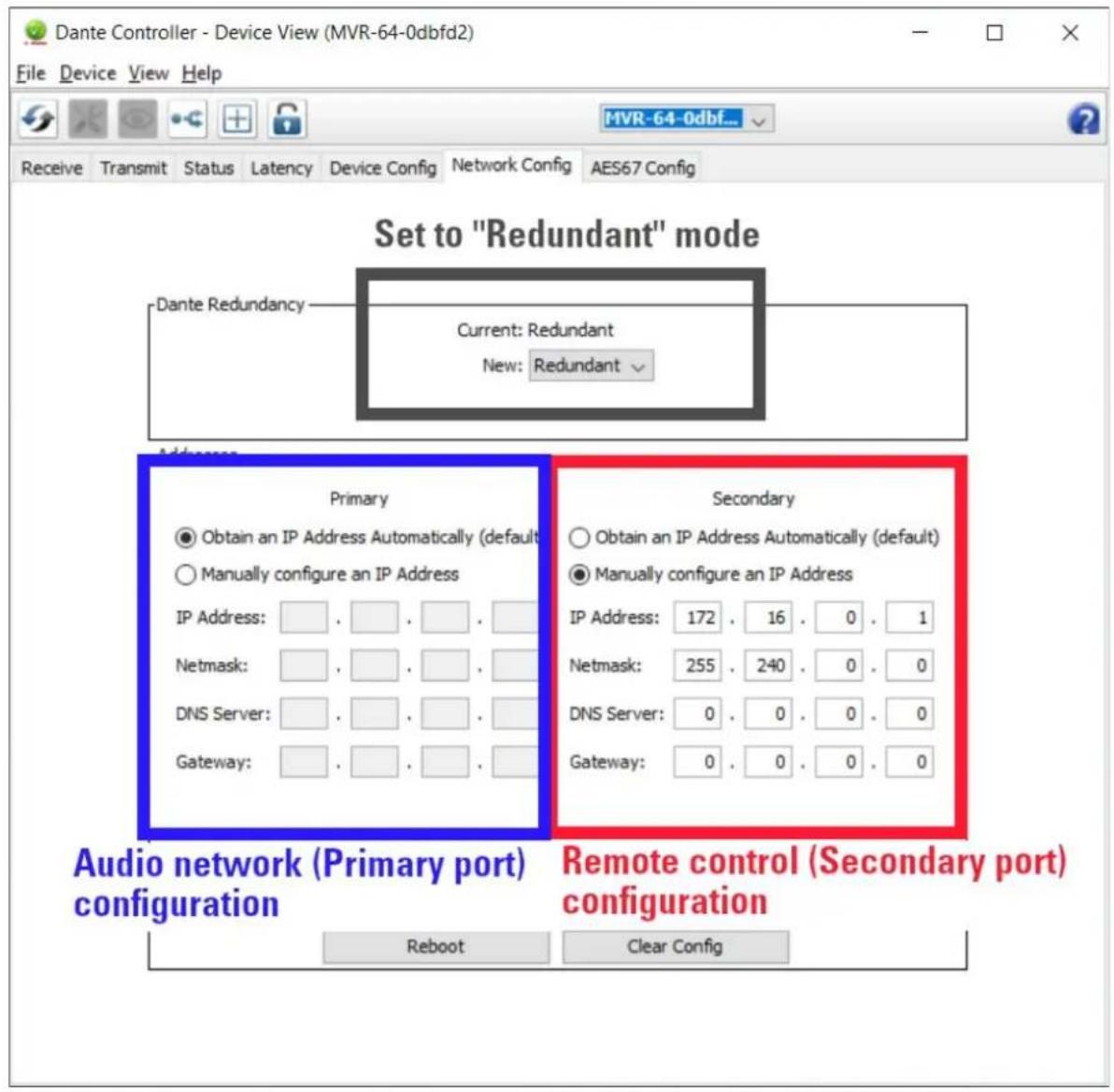
(B) on a separate network, isolated from the Dante audio. In this case, the "Primary" port is used for audio, while "Secondary" port is used for remote control.
|A| Remote control on the audio network
To access the web control, figure out the symbolic name as displayed in the Dante controller, usually MVR-64-xxxxxx (with xxxxxx being some individual number of the multiverted), and type the following into the browser's address bar:
http://MVR-64-xxxxxx.local
Alternatively, you can type the IP address of the Dante module as displayed in the 'Network Config' tab into the address bar, e.g. 192.168.0.204 Please note that, depending on the network configuration, the module's IP address can be reassigned by the server.
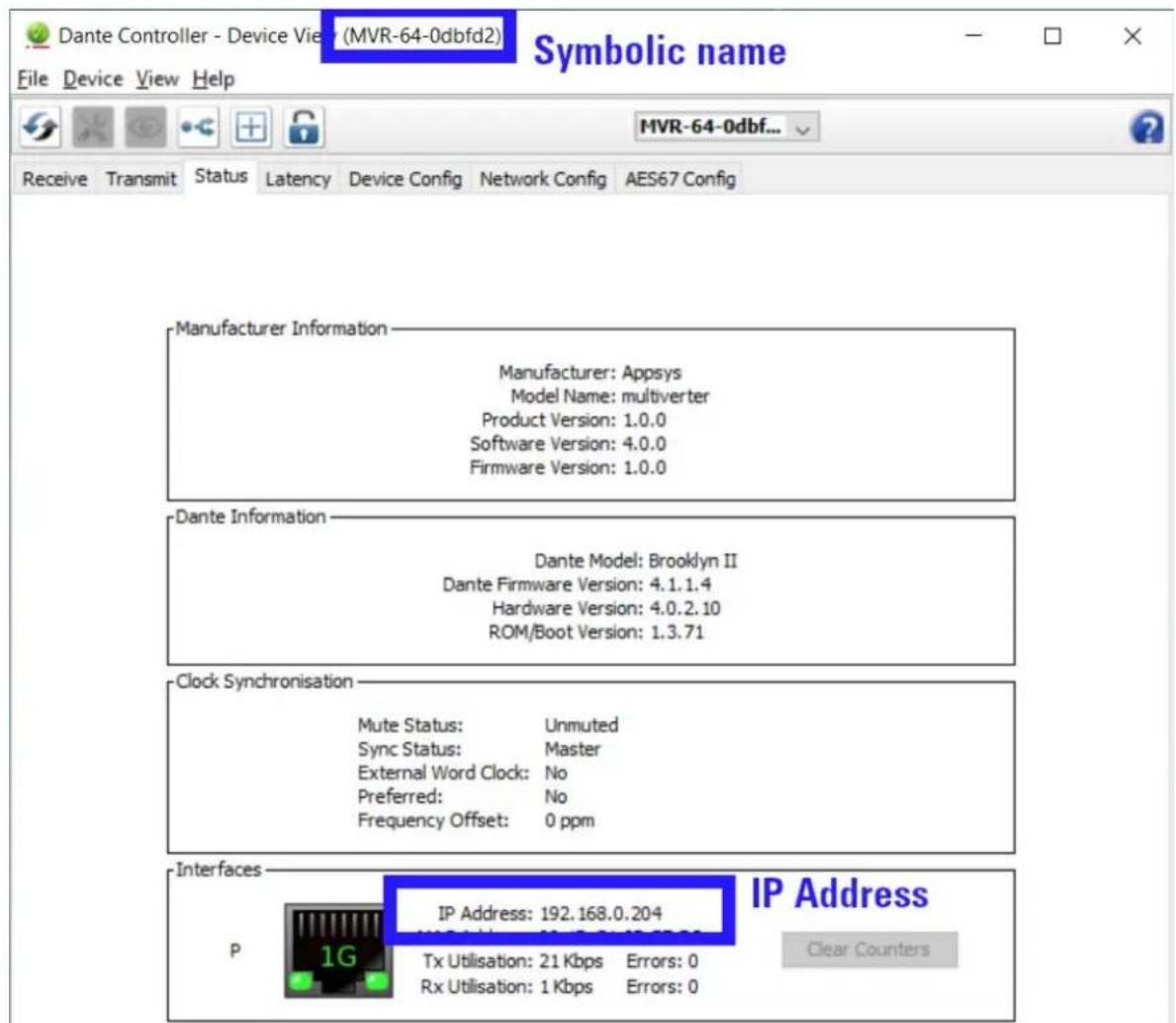
(B) Remote control on a different network
■In the Dante Controller, under 'Network Config', set Dante Redundancy to "Redundant".
■Connect the Audio network to the 'Primary' port only and configure it as desired.
■Connect the Control network to the 'Secondary' port and configure it as desired.
General remote control considerations
■The app uses latest web technologies (HTML5, AJAX, Server-sent Events etc.) which require an up-to-date browser. It has been extensively tested with mid-2018 editions of Chrome, Firefox, Safari and Edge. Older browsers - including all versions of Internet Explorer - are not supported!
■You can run up to four sessions at the same time (i.e. have the page open on four different computers). Any change or status update will propagate within a few seconds to all connected devices.
■Web control has been carefully designed to transfer data only when a change occurred (and even then only a few bytes) so it generates virtually no additional load on the Dante network.
▶Command line
Command line control is available via standard telnet, and also on USB |FT2232 COM port). It provides access to all multiverter functions and routings, and is perfectly suited for automated tasks.
■The telnet server listens on the Dante network, on port 2300. Use a telnet client to connect to it:
telnet MVR-64-xxxxxx.local 2300
Alternatively, you may use the |P address of the Dante module, either on the audio network on a separate control network |see Web Control.
■When connected via USB, the multiverters shows up as COM port. Communication can be done with a standard serial terminal i.e. PuTTY or minicoml. Communication parameters are 115200,8N1.
■ To obtain a list of all commands, type help at the MVR> command prompt and press enter.
■To exit a command line session, type exit end press enter.
▶M|D|
The only command understood via M|D| is "Preset Recall". See 4.1. Preset Recall for details.
Besides this command, the M|D| port may be used to receive and transmit M|D| data in order to embed/de-embed it to any MADl stream. See 3.14. Control data forwarding for details.
3. CONNECTIONS OVERVIEW
This chapter gives you an overview of all connections on the back of the device. Please refer to 12. Specifications for full characteristics of each port.
3.1. AC Power
Mains AC inlet, 90-240VAC, 0.75A max.
Together with the DC power port, the inputs are full redundant. If any of the inputs fail, the other takes immediately over. During the switch-over process, full operational state is maintained (i.e. no interruptions in the audio flow).
3.2. DC Power
Battery | DC inlet, nominal 9·18V, tolerates up to 30V.
Maximum current 2.5A, typical operating current < 1A, standby current ca. 10 mA.
Use this port
■to operate independently from AC power, e.g. from a camera battery pack in the field
■as battery backup if the AC input(s) fail. To prevent the backup battery from draining while AC power is present, keep the voltage below 16 volts.
3.3. ADAT/SPD|F/AES3 optical
Eight optical input/output ports are available. Each input and output port can be run in different modes:
■ADAT with up to 8 channels per port
■SPDIF with up to 2 channels per port
■AES3 optical with up to 2 channels per port
For the inputs, the mode is detected automatically. For the outputs, the desired mode can be set individually via the Web UI on the SETTINGS page (see 9.2 Configuration settings).
The ports are mapped to the channels as shown in the table below. Please note that SPD|F|AES3 channel mapping is not linear, but starts with the same channel number as ADAT for each port. This allows to keep all routings the same even when the protocol changes.
| Protocol SMUX 1 2 3 4 5 6 | Port | ||||||||
| 7 8 | |||||||||
| ADAT x1 1..8 | 9..16 17..24 25..3 | 2 33..40 | 41..48 4 | 9..56 57..64 | |||||
| SPD|F / AES3 | x1 | 1..2 | 9..10 | 17..18 | 25..26 | 33..34 | 41..42 | 49..50 | 57..58 |
| ADAT | x2 | 1..4 | 5..8 | 9..12 | 13..16 | 17..20 | 21..24 | 25..28 | 29..32 |
| SPD|F / AES3 | x2 | 1 | 5 | 9 | 13 | 17 | 21 | 25 | 29 |
| ADAT | x4 | 1..2 | 3..4 | 5..6 | 7..8 | 9..10 | 11..12 | 13..14 | 15..16 |
| SPD|F / AES3 | x4 | no: supported | |||||||
Table 1: Optical port channel mapping
When ADAT, SPDIF or AES3 is used as clock source, Port 1 must be connected and is used as master clock.
3.4. PC/USB
The USB port is used for firmware update, and as Remote Control Port for the PC (serial terminal, 115200, 8N1. See Command line on p.11 for details).

The USB port does NOT carry audio data!
To interface the audio system of the multiverter to a computer, connect is using Ethernet to the Dante port and use the Dante Virtual Soundcard software.
3.5. RS485
The RS485 port is prepared to send and receive Yamaha Headamp Remote control information*.
3.6. Extension
This port is designed to connect break-out boxes to support other, non-built-in protocols and standards [e.g. AVB], or to connect additional ports for system extension.
Currently supported (as of 2019-08):
| Product Purpose | |
| MTA-64 Adapter | for DiGiCo|Soundcraft|Studer|Harman MADl-TP variantNote: The MTA-64 uses the Extension port only for power, not for audio. The port is fed through on the MTA-64 and remains available for other extension boxes. |
Please contact us for the scheduled availability of other break-out boxes.

Two multiverters can be connected together via the extension port when a larger number of different ports is required.
Note: Although this port makes use of a standard HDMI connector, it is NOT compatible with HDMI devices. Don't connect HDMI equipment! The HDMI connector was chosen because cables are ubiquitous and can easily be replaced (and also because the electrical characteristics are perfectly suited for this purpose).
3.7. MAD | optical
This port carries MADl data, according to the "optical" transmission method specified in AES10.
The yellow LED indicates the current status:
■Off: No incoming MAD data detected
■On: Incoming MAD detected, but no valid system clock
■Flashing: Incoming MADl and valid system clock detected
Control data e.g. for preamp control can be forwarded over this port. See 3.14, Control data forwarding for details.

Where possible, use the "MADl optical" connection rather than BNC or TP connections to reduce the chances of noise/interference and to increase reach.
3.8. MAD | BNC
This port carries MADl data according to the "coaxial" transmission method specified in AES10.
The yellow LED indicates the current status:
■Off: No incoming MAD data detected
■On: Incoming MAD detected, but no valid system clock
■Flashing: Incoming MADl and valid system clock detected
Control data (e.g. for preamp control) can be forwarded over this port. See 3.14, Control data forwarding for details.
3.9. MAD | TP
This port carries MADl data, according to the "MADl over Twisted Pair cabling" method specified in the draft for the upcoming AES10 standard (AES-X-213).

To interface to the DiGiCo or Soundcraft/ Studer/Harman variants of MADl-TP, an external MTA-64 adapter is required. See
The LEDs indicates the current status:
■Yellow: Link detected
■Green: Input data valid and system clock valid
This port can also be used as second AES50 port (adapter cable and altered setting required - see 9.2 Configuration settings, and 13.1 AES50/MAD|TP Pin swap adapter cable). This second port may be used either as standalone port (48ch) or in channel aggregation mode, meaning that both AES50 ports are treated as one single interface with the first port carrying channels 1-48|1-32 |1-24|1-16 @96kHz and the second port carries channels 49-64|33-64|25-32|17-32 @96kHz.
Control data (e.g. for preamp control) can be forwarded over this port. See 3.14, Control data forwarding for details.
3.10.AES50
This port carries Behringer|M|DAS compatible digital audio data (48ch @ 48kHz, 24ch @96kHz). It is also prepared to transmit control data from and to
Behringer|M|DAS preamps |i.e. for remote gain control}.*
The LEDs indicates the current status:
■Yellow: Link detected
■Green: Input data valid and system clock valid

To use more than 48|24 channels with AES50, the MAD|-TP port can be configured to work as second AES50 port. Use the channel-wise routing feature from the Web remote to map the channels as required.
This port can also be switched to work as second MADI-TP port (see 9.2 Configuration settings, and 13.1 AES50|MADI-TP Pin swap adapter cable). In MADI-TP mode, Control data (e.g. for preamp control) can be forwarded over this port. See 3.14, Control data forwarding for details.
3.11. Word clock
The wordclock input accepts a square wave signal in the frequency of the sample rate. x2 and x4 modes are automatically detected when the square wave has x2|x4 frequency, and can be manually set when the square wave has x1 frequency.
A 75 ohms termination resistor can internally be switched but is OFF by default. Altering the setting requires opening of the device, please contact us for further information.
The wordclock output is a square wave signal (50% duty cycle) and is able to drive up to two 75 ohm resistors in parallel. Its frequency is either identical to the sample rate or always x1 (see 9.2 Configuration settings).
3.12. Dante / AES 67
The "Primary" and "Secondary" ports are standard gigabit Ethernet ports, designed to connect to Dante Digital Audio Network. AES67 mode is alternative to Dante mode and can be set in the Dante Controller Software.

The Dante port provides also the Web UI and a telnet server (on port 2300) for remote control. Both services are available on the same IP address as the Dante audio interface | use the Dante Controller software to determine or change the |P|.
The port LEDs indicates the current status:
■Yellow: Link detected
■Green: Input data valid and system clock valid
Please refer to the Audinate website for information about Dante Technology, the latest Dante Controller drivers and related information.
By default, the ports are configured to act as switch (which allows daisy chaining), but can be changed using the Dante Controller Software as redundant ports for parallel connection.
3.13.M|D
The only command supported via the M|D| port is "Preset Recall". See 4.1 Preset Recall.
The yellow LED near the port flashes when incoming M|D| data is detected. All incoming data is forwarded to the M|D| THRU port, to allow daisy-chaining of devices.
Control data (e.g. for preamp control) can be forwarded over this port. See 3.14, Control data forwarding for details.
3.14. Control data forwarding
The multiverter is able to forward control data {headamp|stagebox control} between MADl ports, and from and to the M|Dl ports. The multiverter provides transparent forwarding of all extra AES3 bits |V|alid, |U|ser data and |C|hannel status, which makes it compatible to all vendor-specific remoting protocols.
To enable remoting, the channels containing the control data must be routed 1:1 (i.e. linearly), depending on the vendor protocol.
| Vendor Control method | |
| DiG|Co Control data | is contained in all bits (audio+user) of channel 57.To enable forwarding between different MADl ports,•Set MADl transmit mode of the involved MADl ports to 57ch(see 9.2 Configuration settings)•Route ch 57 to ch 57 both ways |
| Soundcraft Control data | data is contained in the 'U' bit of channels 1..10.•To enable forwarding between different MADl ports, route ch 1..10 to ch 1..10 both ways |
| RME, FerroFish, DirectOut|M|D| over MAD| | Control data is contained in the 'U' bit of channel 56 |ch28 in 96k model•To enable forwarding between different MADl ports, route ch 56 to ch 56 both ways.•To enable forwarding from|to the M|D| ports on the rear to|from a particular MADl port, set '[08] M|D| forwarding" to the desired MADl port |see 9.2 Configuration settings| |
Table 2: Remote control over MADI
4. PRESETS
All settings (excluding headphones level) can be individually stored in one of the 12 preset locations, and may be recalled at any time later. The settings are stored in non-volatile memory and are retained for years even if the device is switched off or the power cable is unplugged. Additionally, the settings can be downloaded via the Web UI, and restored on the same or a different device.
4.1. Preset Recall
▶Front panel
To recall a preset:
■Push the Recall button from the "Preset" menu.
■ Select the desired storage location ☑1 to ☑12 by turning the encoder left or right.
■Note: The presets "Test tone" and "Function" have special purposes.
See 9. Advanced Topics.
■Confirm the selected location by pushing the encoder, or push the
Back button to cancel the operation.
▶We b
From the "PRESET" menu, choose the desired preset number. An asterisk next to the number indicates that modifications to the recalled preset have been done. To save the modifications, choose "PRESET! Store".
Note: You can also upload presets from a file to the MVR. This is useful when transierring setups between different multiverters.
▶Command line
preset recall
▶M|D|
Preset recall is done via "Program Change" messages
(program 00 = Preset 1 ... program 11 = Preset 12).
The MD channel is set to 1 by default but can be altered using function "07".
(Note: The channel is a per-preset setting, if you need to change it you will need to do so in all 12 presets).
4.2. Preset Store
▶Front panel
To store a preset:
■Push the Store button in the "Preset" menu.
■ Select the desired storage location ☑1 to ☑12 by turning the encoder left or right.
■Confirm the selected location by pushing the encoder, or push the Back button to cancel the operation.
▶We b
Select 'PRESET / Store' menu to store the preset as current preset number, or ▼ select 'PRESET / Store as...' to choose a different number.
Note: You can also download presets to a file. This is useful when transferring setups between different multiverters.
▶Command line
preset store [
4.3. Changed presets
▶Front panel
When a preset is recalled, the corresponding location 1 to 12 is lit green. If any setting is changed afterwards (except for headphones level), the LED turns red to indicate that the current setting differs from the recalled preset. If you want your changes to be reflected also in the stored preset, just store the preset again. Otherwise, the changes are overwritten the next time a preset is recalled.
▶Web
A changed preset is indicated by an asterisk |*| next to the preset number. Use 'PRESET | Store' to permanently store changes into that preset.
▶Command line
A changed preset is indicated by an asterisk |*| next to the preset number. The current preset can be queried by calling preset without parameters.
4.4. Auto·Store
In addition to the presets stored in locations 1-12, the multiverter remembers always the current setting, even when power cycled or left unpowered for a long time. This means that you can always reset the multiverter and have the settings fully restored by switching it off and on.
5. ROUTING

Due to a lack of controls, the front panel allows only interface-wise routing. To use channel-wise routing (merging of different input streams), use either the web interface or the command line.
▶Front panel
The routing matrix indicates the interfaces between conversions are currently active.
■A green LED means that a connection is made between the two interfaces, and a conversion is currently in progress.
■A red LED means that a connection is made, but inactive because the input or clock signals are missing.
■A yellow LED means that a test tone is currently output instead of the input signal.

Routing is easy if you think this way: "I want this input mapped to this output"
To make or break a connection in the Routing matrix:
■Push the Set button in the "Routing" menu
■A yellow blinking cursor indicates the current position within the matrix. Move it by turning the encoder to the desired point where you want to make or break a connection.
■At the beginning or end of the line, continue to turn to the right to make the cursor wrap around to the previous or next line.
■ Push the encoder or press the Set button to make break a connection. When the cursor blinks yellow/red or yellow/green, the connection has been made; when the cursor blinks yellow/dark, the connection was broken.
■ To exit the routing matrix, push the Back button.
▶We b
The web interface allows fine-grained routing control in different levels (whole interfaces, channel groups or single channels). Routes can be entered via either Matrix or List view (both can be used interchangeably, and routings established in one view show immediately up also in the other).
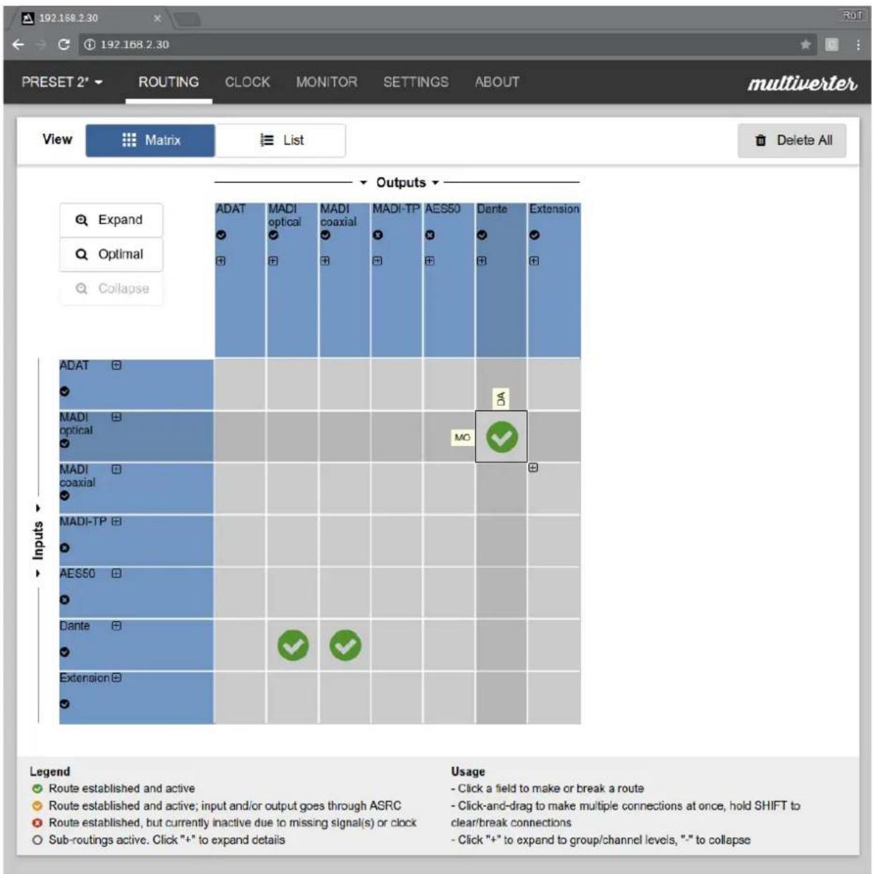
Matrix view: ideal for quick routings, everything on one glance. The arrangement is the same as on the front panel
■Click anywhere in the matrix to make or break a connection. Multiple connections can be made by click-and-drag, broken by holding SHIFT.
■Current status of a connection is indicated by the large colored icon on the connection; current status of each input / output is indicated smaller on the header.
■ The matrix can be expanded to group- and channel-wise views via + and buttons on rows [inputs], columns [outputs] or intersections (connections).
■ The "Expand" and 'Collapse" buttons zoom the entire matrix. Use the 'Optimal' button to expand to all sub-routings.
■To clear all connections, click 'Delete All'.
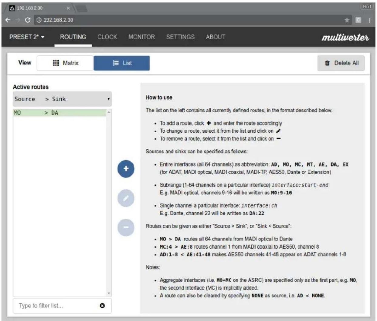
List view: quick way to establish complex routings
■ Each routing can be entered as text line, in the form "Source > Sink" or alternatively "Sink < Source" (both produce identical results).
■ "Sink" and 'Source' can be entire interfaces, channel ranges or single channels. Entire interfaces are be specified as two-letter abbreviation (i.e. "MO" for MAD optical)
■Channel ranges can be specified by appending a colon, followed by the start and end channels.. For example, Dante channel 9 to 16 would read "DA:9-16"
■Single channels are specified by appending a single the channel number to an interface, separated by a colon. For example, AES50 channel 24 would read 'AE:24'
■Example 1: to route all channels from AES50 to MADl coaxial, enter 'AE > MC" (or alternatively, "MC < AE")
■Example 2: to route channels Dante 56-64 to ADAT channels 1-8, enter 'DA:56-64 > AD:1-8" (or alternatively, "AD:1-8 < DA:56-64")
■Example 3: to route MAD | TP channel 2 to Extension channel1 | 1: 'MT:2 > EX:1' | or alternatively, "EX:1 < MT:2"
▶Command line
route
with
6. CLOCKING
All components within a digital audio system must reference to the same master clock to ensure that they run synchronously. The multiverter can use any of the incoming interfaces as clock source, or alternatively it can act as clock master using its internal, high-quality clock synthesizer.

If a common clock is not possible (e.g. when incoming data has a different sample rate), the optional ASRC module can be used to convert the data to the multiverter's main clock.
See the ASRC manual for details.
6.1. ClockShield
The multiverter's unique ClockShield feature allows the device to run up to one second (!) without a master clock signal. This makes the multiverter very robust against disturbances, glitches and dropouts in the clocking system.
How it works:
■When the clock signal is lost, the multiverter's clock continues to run for up to one second, at the frequency which it has been locked to when the clock was valid. During that period, audio processing continues as before.
■When the clock signal is re-applied, re-synchronization takes place to ensure perfect bit-wise alignment of data and clock. To avoid pops and clicks, all audio signals are soft-muted before the re-sync happens, and are soft unmuted directly after re-sync. The whole process takes only a few milliseconds and produces only minimal artifacts, often not even audible.

ClockShield is supported on all interfaces, but works best when the multiverter is clocked from the BNC wordclock input.
6.2. Clock source selection
▶Front panel
To set the main clock source:
■Push the Set button in the "Clock" menu.
■Move the yellow blinking cursor to the desired clock source.
■ Push the encoder or press the Set button to select the interface, or press Back to cancel.
■Depending on the selection, you will be asked to provide additional information:
■ When the clock source is set to internal ☑|NT| you will be asked for the sample frequency where the internal clock should run at. Choose one from the 32kHz to 192kHz, or press Back to return to the clock source selection. NOTE: Not all sample rates (especially the 32/64/128kHz modes) are available on all interfaces.
■ When MADl optical ☑ M0, MADl coaxial ☑ MC, MADl-TP ☑ MT or BNC wordclock ☑ WCLK is chosen, you need to set whether the multivertor should run in x1 {32|44.1|48kHz}, in x2 {64|88.2|96kHz} or in x4 {128|176.4|192kHz}. Choose the desired mode and push the encoder to confirm, or press return to the clock source selection.
Note: Regardless of the selection, the multiverter will always run in x2 mode when MAD196k frames are received.
▶We b
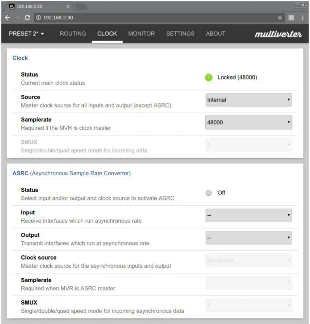
The main clock parameters can be configured on the 'CLOCK' page. When the ASRC module is installed, its behavior (asynchronous interfaces etc.) can be selected in the ASRC section on the bottom.
▶Command line
clock [
■Available Sources: AD, MO, MC, MT, AE, DA, EX, WCLK, INT
■ Samplerate (only required for DA or INT):
44100, 48000, 64000, 88200, 96000, 128000, 176400, 192000
■ SMUX | only required for AD, MO, MC, MT or WCLK: 1, 2, 4
asrc [disable|
■ disable Turn off ASRC
■ <in>,<out> Interfaces which should run asynchronously.
Values: AD,MO,MC,MT,AE,DA,EX,MO+MC,MO+MT,MC+MT,AE+MT,NONE
If NONE is specified, the ASRC is turned off for the respective direction. If both
<in> and <out> are set to NONE the ASRC is turned off.
■ <clksrc> Interface where the ASRC takes its clock from
■ <srate> Samplerate [for DA,INT], values see 'clock' command
■ <smux> SMUX [for AD,MO,MC,MT,WCLK]: 1,2,4
6.3. Dante Clock
The Dante network itself needs one device which acts as "Network clock master" (not to be confused with the system clock master, which may also be a different device!)
The selection of the network clock master can be done in the Dante Controller software, and must be done depending on the multiverters' main clock source:
| multiverter clock source|set on multiverter| | Dante network clock master(set in Dante controller software) |
| Dante module *DA | any Dante node |except Dante Virtual Soundcard| |
| all other sources only multiverter possible |
Table 3: Dante clocking modes
7. PANEL LOCK
▶Front panel
The panel lock feature can be used to disable all buttons on the front panel. This can be used to protect the MVR-64 against undesired or accidental parameter changes. The panel lock feature is available from firmware version 1.4 and higher.
■ To lock the panel, hold down the Back button while pushing the encoder. The seven-segment display will blink to indicate the now locked panel. All buttons on the front panel are now disabled.
If a button is pressed while the panel is locked, the seven-segment display will blink to indicate the locked panel.
■ To unlock the panel, hold down the Back button while pushing the encoder.
8. MONITOR
The "Monitor" section controls the headphone amplifier which allows you to listen to any channel received on the inputs.

You can adjust if mono (same channel on both ears) or stereo signals are output on the headphones. Also, extra gain
(+6|+12|+24dB| can be added for the headphones output to ease monitoring of silent signals (but may cause clipping at larger levels).
To adjust these settings, see 9.2. Configuration settings
▶Front panel
To select a particular input to listen to:
■Press the Set button in the "Monitor" menu.
■Move the yellow blinking cursor to the desired interface.
■ Push the encoder or press the Set button to select the interface, or press Back to cancel.
To select a channel:
■ Make sure that ⚙Ch mode is selected. If not, push the encoder once.
■Rotate the encoder left to decrease the channel, or right to increase the channel. In stereo mode, the selected channel is output on "L" whereas the subsequent channel is output on "R".
To change the volume:
■ Make sure that ☑ Vol mode is selected. If not, push the encoder once.
■Rotate the encoder left to decrease the volume, or right to increase the volume.
▶We b
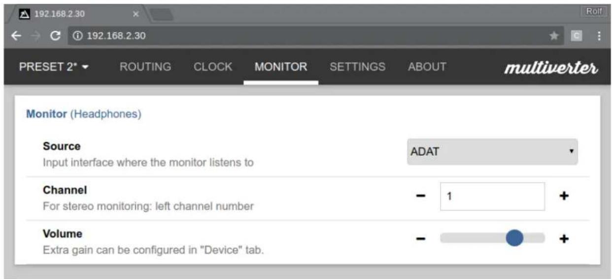
The "MONITOR" page allows to set the source interface, channel and volume for the headphones. More settings [stereo:mono mode, gain] can be found on the "SETTINGS" page.
▶Command line
monitor [
Sets the source interface and channel. If stereo monitoring is selected,
volume [
Sets the volume of the monitor output, either as
9. ADVANCED TOPICS
9.1. Test tone mode
▶Front panel only
For diagnostic purposes, the multivertor is able to play a test tone (1kHz, -20dB sine wave) on all outputs which are currently active. This feature is especially helpful to determine problems in your signal flow, as it does not rely on any external sources [except for the clock].
To enter test tone mode:
■Push the blue Recall button
■ Move the cursor to ☀ Test tone by turning the encoder left or right
■ Confirm your selection by pushing the encoder, or push Back to cancel the operation.
■The test tone mode is now active. All outputs which are active in the Routing matrix are replaced by the test tone signal indicated by yellow lit LEDs in the Routing area.
To exit testione mode:
■Push the blue Recall button
■Move the cursor to "Test tone" by turning the encoder left or right
■ De-select Test tone mode by pushing the encoder, or push Back to cancel the operation.
9.2. Configuration settings
The multiverter offers fine-tuning of various parameters and seldom used settings via the "Function" item in the Preset menu, or via the web interface. The "index" indicates the parameter to change, while the corresponding "value" reflects its current setting. A complete list of "index/value" pairs can be found in the table below.
▶Front panel
The "function index" is indicated by ☑1 to ☑12 in the "Preset" menu, while the corresponding "value" is displayed in the 7-segment display.
To adjust a particular setting:
■Push the blue Recall button
■ Move the cursor to Function by turning the encoder left or right
■ Confirm by pushing the encoder (or push Back to cancel the operation).
■The Function LED should now be lit.
■ Move the cursor to the desired index ☉1 to ☉12
■ Confirm by pushing the encoder (or push ▶Back to cancel the operation)
■The current value is displayed in the 7-segment display. Rotate the encoder to change the value, and push it to confirm.
▶Web
![appsys.ch/livedemo/mvr-64/ Not secure | appsys.ch/livedemo/mvr-64/ PRESET 1* ROUTING CLOCK MONITOR SETTINGS ABOUT DEMO multiverter Parameter settings (* indicates default setting) [01] Headphones mode Extra gain may cause clipping on large signals! Mono +0dB [02] MADI optical transmit mode Output format for MO (input always auto-detected) Standard MADI (AES10) *64ch *96k frame [03] MADI coaxial transmit mode Output format for MC (input always auto-detected) Standard MADI (AES10) *64ch *96k frame [04] MADI-TP port operation mode AES50 requires pinswap, DiGiCo/Soundcraft requires MTA-64 *AES-X-213 *56ch 48k frame [05] AES50 port operation mode AES-X-213 requires pinswap, DiGiCo/Sndcr. pinswap+MTA-64 *AES50 58ch 40k frame jumpered to address 2 [06] Wordclock output *00: BNC output frequency equal to samplerate [07] MIDI channel for Preset Recall Per-preset setting, alter in other presets if required! *1 [08] MIDI forwarding Interface to embed/extract MIDI data from/to MIDI jacks *00: Disabled [10] Display brightness Set the brightness of the LEDs on the front panel - + [13] ADAT/AES3/SPDIF output Configures the output format for each port (input is always auto- detected) 1 2 3 4 5 6 7 8 ADAT AES3 SPDIF](/content/2026/05/835231/images/bc277a7257b7a2eca42941767466ab2627263343721f99c42abaa2abe632ba49.jpg)
The 'SETTINGS' page contains various fine-tuning parameters.
An asterisk * indicates the default setting
▶Command line
function
| Index Purpose bold default setting | |||||||
| [01] Headphones mode Value Mode Extra Gain | |||||||
| *01 Mono +0dB (none) | |||||||
| 02 Stereo | |||||||
| 03 Mono +6dB | |||||||
| 04 Stereo | |||||||
| 05 Mono +12dB | |||||||
| 06 Stereo | |||||||
| 07 Mono +24dB | |||||||
| 08 Stereo | |||||||
| Mono: Both L and R speakers of the headphones play the same monitor channel. The channel indication ranges from 1 to 64 and changes in steps of 1.Stereo: Odd channels are played on the L speaker and the subsequent channel is played on the R speaker. The channel indication ranges from 1 to 63 and changes in steps of 2Extra gain may cause clipping on large signals. | |||||||
| [02][03] | MAD optical transmit mode ^1 MAD coaxial transmit mode ^1 | Value Number of channel | s 96k frame format | ||||
| 00 56 48k | |||||||
| 01 96k | |||||||
| 02 64 48k | |||||||
| *03 96k | |||||||
| 32 57 48k | |||||||
| 33 | 96k | ||||||
| [04][05] | MADI-TP port operation modeAES50 port operation mode | Value | Mode | Num.Ch | 96k frame format | Pinout mode | Remarks |
| 00 | AES-X21348k | 56 | 48k | Auto | |||
| 01 | 96k | ||||||
| 02 64 | |||||||
| 03 | 96k | ||||||
| 04 | AES50 | 48 | |||||
| 08 ‡ | DiG Co | 56 | 48k | Straight | MTA-64 required | ||
| 09 ‡ | 96k | ||||||
| 10 ‡ | 64 | 48k | |||||
| 11 ‡ | 96k | ||||||
| 12 ‡ | SoundcraftStuder13 # 9 | 566k | 48k | ||||
| 14 # 64 48k | |||||||
| 15 # 96k | |||||||
| 24 # DiGiCo | 56 48k MD X | (Crossover) | |||||
| 25 # 96k | |||||||
| 26 # 64 48k | |||||||
| 27 # 96k | |||||||
| 28 # Soundc | afti Studer | 56 48k | |||||
| 29 # 96k | |||||||
| 30 # 64 48k | |||||||
| 31 # 96k | |||||||
| 32 AES-X213 | 57 48k Auto | ||||||
| 33 96k | |||||||
| 40 # DiGiCo | 57 48k Straight MTA-64 | required | |||||
| 41 # 96k | |||||||
| 44 # Soundc | afti Studer | 57 48k | |||||
| 45 # 96k | |||||||
| 56 # DiGiCo | 57 48k MD X | (Crossover) | |||||
| 57 # 96k | |||||||
| 60 # Soundc | afti Studer | 57 48k | |||||
| 61 # 96k | |||||||
| #:MTA-64 adapter requiredGeneral: Using the MADl-TP port as AES50 or vice versa is possible, but requires a pinswap cable (see chapter 13.1) due to the different pinout. | |||||||
| [06] Word clock output mode | *00 = Wordclock output frequency identical to sample rate01 = Wordclock output frequency is always single speed (base sample rate) | ||||||
| [07] MD channel 01...16 | Default: 01.NOTE: This is a per-preset setting remember to change on all presets! | ||||||
| [08] MD forwarding Configures from to which MADl interface the data on the M|D jacks is routed.*00 = Disabled01 = MADl optical02 = MADl coaxial03 = MADl-TP04 = AES50 (in MADl-TP mode only) | |||||||
| [09] Reserved | |||||||
| [10] | Display brightness | 01..05. Default: 05 | |||||
| [11] | Service menu | 01 = Self-test [external cabling required, see 9.5. Audio Interface self-test]02 = LED and button test. See 9.6 LED and button test03 = ASRC self-test. See 9.7 ASRC self-test99 = Reset to Factory Defaults | |||||
| Index Purpose Values (bold: default setting) | ||
| [12] | Version info | Note: The firmware consists of several different parts. To check the overall firmware version number, use the web interface.Turn the encoder left or right to display the different version numbers in the 7-segment display:AD* FPGA Firmware Major versionMO* FPGA Firmware Major versionMC* Control Firmware Major versionMT* Control Firmware Minor version*AE Hardware version MainboardDA* Hardware version Front panel*EX ASRC Firmware Major version ['--' if not installed]*Ch ASRC Firmware Minor version ['--' if not installed]*Vo| Hardware version ASRC ['--' if not installed]Press→Backto exit the version display mode. |
| [13] ADAT transmit modesNote: Cannot be configured from the front panel - use Web UI instead! | Sets the output mode for each ADAT port.Possible values:ADAT: 8 channels ADAT formatSPDIF: 2 channels (stereo), header in consumer formatAES3: 2 channels |stereo|, header in professional format | |
Table 4: Configuration settings
9.3. Audio Interface self-test
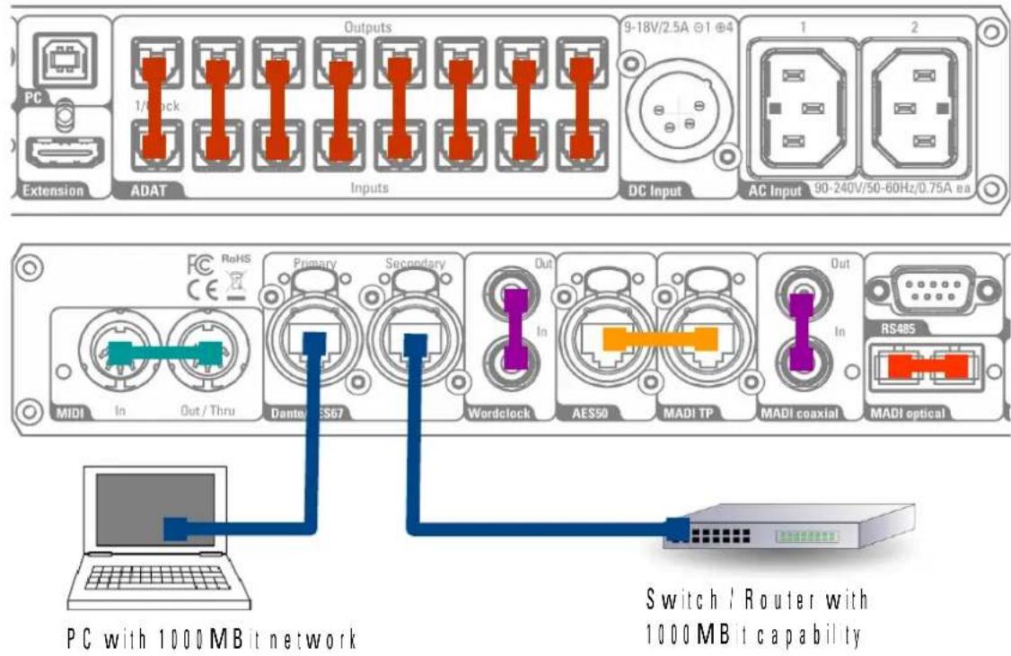
The MVR-64 can check itself for correct operation. This is done by sending a special signal out on every interface through an external loop back and monitor the received data for correctness. When the received data is correct, the respective LED on the front panel turns green.
To perform the self-test,
■ Connect the cables in loop-back mode as shown below
NOTE: If you want to test a specific interface only, it is sufficient to wire the loop-back on that interface only and monitor the respective LED
■ Enterself-test mode by pushing Recall move to Function confirm with
OK move to *11 push OK turn encoder until display shows 01 and confirm with OK
■ On the headphones output, a 1 kHz sine wave is played on both channels.
■ During the self-test, SET is shown in the seven-segment display. To return to normal operation, press Back
| LED indication | |||
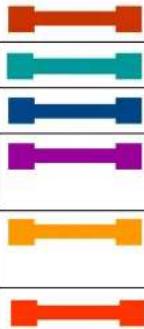 | 8x optical TOSLINK (ADAT) cable AD/AD | ||
| MDI cable (2x 5-pin D|N plug) | |||
| Standard 1:1 network cable DA|DA | |||
| BNC cable, 75 ohms MC|MC | WCLK | ||
| AES50 |MADI-TP pin swap cable, see chapter 13.1 AE/AE | MT|MT | ||
| MADI optical loop-back cable MO|MO | |||
Table 5: Self-test wiring
9.4. LED and button test
To verify correct operation of all LEDs and buttons,
■ Enter LED button test mode by pushing Recall move to Function confirm with OK move to 11 push OK turn encoder until display shows "02" and confirm with OK
■During the test, all front-panel LEDs show the same color. Each button press cycles the color, and Back exits the test. The seven-segment display shows 88 and 8 alternatively.
■The LEDs on the back are constantly lit during the test, except for the Dante LEDs which maintain normal operation.
9.5. ASRC self-test
The SRC-64 sample rate converter can be self-tested for correct operation. A 1kHz, 96k sine wave is passed through all channels of the ASRC (down-sampled to 88.2k), and looped back (up-sampled to 96k again).
The result can be listened to on the headphones and is also present on MAD optical (ch 1-32) and MAD coaxial (ch 33-64).
■ Enter ASRC self-test mode by pushing Recall move to Function confirm with OK move to 11 push OK turn encoder until display shows 03 and confirm with OK
■Plug in headphones. Turn the encoder and listen carefully to channels 1 to 64, one after another.
On all channels a clean 1 kHz tone should be audible.
■ Press ↩ Back to exit the test.
10. FIRMWARE
10.1. Version check
We recommend to check the firmware via the Web interface ['ABOUT' tab]. Only there is the overall version number |= package version, same as in the file name of the firmware ZIP-file visible. Else you will see only component sub-versions.
▶Frontpanel
Push Recall move to Function confirm with OK move to 12 push OK The different versions are shown in the 7-segment display according to Table 4: Configuration settings, index 12.
NOTE: This lists only the component sub-versions and not the overall firmware version.
▶We b
Click the 'ABOUT' tab. The overall firmware version number is displayed as "Firmware version: X.Y".
▶Command line
Version
NOTE: This lists only the component sub-versions and not the overall firmware version.
10.2. Upgrade

Firmware upgrade involves two operations which must be both carried out (order doesn't matter):
1) FPGA|Frontpanel{via USB and command line tool}
2) Dante upgrade (via Dante network connection)
- The FPGA and Control firmware is updated via the USB port.
Connect the MVR-64 via USB to your PC and run
MVR-64-Updater.bat | on Windows
or sudo ./MVR-64-Updater.sh (on Linux)
and follow the instructions on the screen.
Mac users: The updater runs also in a bootcamp Windows session, when both
COM ports are mapped to windows.
- The Dante firmware is updated using the Dante Firmware Update Manager
[available for Windows and Mac]. The MVR must be connected to the Danie network. Select 'Update Firmware' and choose the
MVR-64-x.x.x.x.dnt
file | can be found in the "firmware" folder in the firmware Z|P file|.
11. COMMAND LINE REFERENCE
The MVR-64 command listed below are available. Type 'help' to see this list. Most commands can be called without an argument and return the current setting.
preset [
volume [
monitor [
clock [
route [
When called with no params, all active routes are printed. When called with
asrc [disable|
function
key
version: Retrieves device version information
config [query] [json]: Set and/or get device config in JSON format. 'query' can be left out or any combination of what to get: ? query changes only since last call, must be specified as first flag in combination with any of the letter options listed below. It has the effect that unchanged options are omitted from the answer * everything c configuration p parameters r routing s status v version
- SPECIFICATIONS
| Parameter Value | |||||||||||
| Dimensions 482x45x2 | 30 mm | WxHxD| | ||||||||||
| Weight 2.25 kg | |||||||||||
| Operating temperature | 0..+50°C, non-condensing | ||||||||||
| Storage temperature | 40..+85°C, non-condensing | ||||||||||
| Power consumption 8 | Typical.. 30W maximumEach AC input: 90..240VAC, 50-60Hz, 0.75ADC input: 9-24VDC up to 30V tolerant, 2.5A peak | ||||||||||
| Channel count Up to 6 | 4 per interface in x1 modesUp to 32 per interface in x2 modesUp to 16 per interface in x4 modesMultiple conversions i.e., Dante<>MADl and ADAT<>AES50l with each using the full channel count can run simultaneously. | ||||||||||
| Sample rates 32 | 44 | | 48 | 64 | 88.2 | 96 | 128 | 176.4 | 192 kHz +1-100ppmVarispeed operation is not supported | ||||||||||
| Latency The table be d | w shows the overall latency (receive+convert+transmit) between the various interfaces in number of samplesFor x1 modes (32/44.1/48kHz), n is 1For x2 modes (64/88.2/96kHz), n is 2.For x4 modes (128/176.4/192kHz), n is 4.The Dante latency "d" depends on the setting in the Dante controller which should be chosen according to the network topology, and can range from 150μs to 5ms. | ||||||||||
| MO 3*n 3*n 3*n 4*n 3*n+d 3*n | |||||||||||
| MC 3*n 3*n 3*n 3*n 4*n 3*n+d 3*n | |||||||||||
| MT 3*n 3*n 3*n 3*n 4*n 3*n+d 3*n | |||||||||||
| AE 4*n 4*n 4*n 4*n 5*n 4*n+d 4*n | |||||||||||
| DA 4*n+d 4*n+d 4*n+d 4*n+d 5*n+d . | |||||||||||
| ADAT ports | 8 input+8 output ports, 64ch @44.1/48kHz, 32ch @88.2/96kHz | ||||||||||
| Parameter Value | |
| PC port USB 20 [FTD] | 2232]. Remote control and firmware update, no audio connection |
| RS485 port Male D-Sub | 9pin, Yamaha AD8HR compatiblePinout: 2=RX-, 3=TX-, 4=TX+, 5=GND, 6=RX+ |
| Extension port HDMI | connector type [not HDMI compatible].64ch @32/44.1/48kHz, 32ch @64/88.2/96kHz, 16ch @128/176.4/192kHz |
| MADl optical port SC | connector, 50/125 μm or 62.5/125 μm multi-mode fiber [MM fiber],1300nm, up to 2km total length.Transceiver can be changed to Single mode [9/125μm] at the factory on request.64ch @32/44.1/48kHz, 32ch @64/88.2/96kHz, 16ch @128/176.4/192kHz56/57/64 channel support, all AES3 bits [U, C, V] preserved |
| MADl BNC port Standard | AES10 coaxial port. Use with up to 100 meters of 75 ohm coaxial cable64ch @32/44.1/48kHz, 32ch @64/88.2/96kHz, 16ch @128/176.4/192kHz56/57/64 channel support, all AES3 bits [U, C, V] preserved |
| MADl TP port AES-X 2 | 13 lupcoming MADl specificationl compatible.64ch @32/44.1kHz, 56ch @48kHz, 32ch @64/88.2, 28ch @96kHz,16ch @128/176.4kHz, 14ch @192kHzPinout: MADI-TP on 4/5, 7/8Alternative use: Second AES50 port, Pinout: Data on 4/5, 7/8; Sync on 1/2, 3/6 |adapter cable required|56/57/64 channel support, all AES3 bits [U, C, V] preserved |
| AES50 port AES50 3.1 | compatible48ch @44.1/48kHz, 24ch @88.2/96kHzPinout: Data on 1/2, 3/6; Sync on 4/5, 7/8Alternative use: Second MADl-TP with Pinout: 1/2, 3/6 |adapter cable required| |
| Wordclock port Output | : 5.0Vpp nominal, able to drive two parallel 75 Ohm terminationsinput: 2.0Vpp...5.0Vpp |
| DanteiAES67 port 2x | G gabit Ethernet, configurable either as "Switch" or as "Redundant connection" in the Dante controller. Device prefix: "MVR64"64ch @32/44.1/48kHz, 32ch @64/88.2/96kHz, 16ch @128/176.4/192kHz |
| MIDl port Standard isolated input, standard MIDl outputData received on N is passed unaltered to THRU | |
| Headphones 2x125 mW | W into 32Ohml@0.01%THD+N|Bandwidth: 22Hz to 22kHz |
| ESD protection | all ports: +/- 15kV |Human Body Model| |
Table 6: Specifications
13. ACCESSORIES
13.1. AES50/MADl-TP Pin swap adapter cable
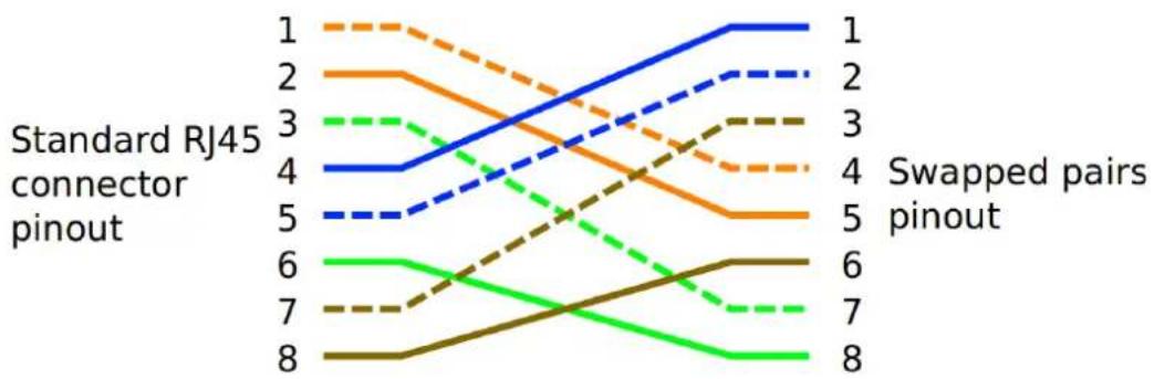
The AES50 and MAD|-TP ports have different pin-outs as required by the respective standards. AES50 uses Pins 1:2 and 3:6 for the signal, 4:5 and 7:8 for sync, while a MAD|-TP port uses 4:5 and 7:8 for the signal (with pins 1:2 and 3:6 reserved - this is where the AES50 sync signal is connected to in the multiverter). To use the alternate function of such a port, an adapter cable with the pinout shown below is required:
line
| Node | Standard RJ45 connector pinout | Swapped pairs pinout | | ---- | ------------------------------ | -------------------- | | 1 | 1 | 1 | | 2 | 2 | 2 | | 3 | 3 | 3 | | 4 | 4 | 4 | | 5 | 5 | 5 | | 6 | 6 | 6 | | 7 | 7 | 7 | | 8 | 8 | 8 |Illustration 1: AES50|MAD|.TP swap cable
13.2. MTA·64 Adapter for MADI·TP
With the MTA·64, the becomes capable of Twisted Pair variants used in DiGiCo and
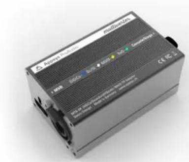
connecting to the MADI-TP | MADI over Soundcraft | Studer | Harman desks. It's connected between the MVR-64's MADI-TP port and the console or stagebox and adapts signal levels and pin-outs.
What's more: you don't need any special crossover cables thanks to internal MDIX logic - any standard 1:1 Cat5 cable will do, no matter if you want to connect to your console or the stagebox.
13.3. SRC·64 Asynchronous Samplerate Converter Module [optional hardware]
The SRC-64 add-on module - available as separate hardware - adds the capability of asynchronous sample rate conversion to your multivertier. Designed as internal
![Appsys ProAudio MVR-64 - SRC·64 Asynchronous Samplerate Converter Module [optional hardware] - 1](/content/2026/05/835231/images/fff79214dcbcb024f1003e72f007ba636fceccb3c8d65c115a83bc6282ffb0ca.jpg)
natural_image
3D rendering of a green printed circuit board with various electronic components and connectors (no visible text or symbols)add-on module, it leaves the 'Extension' port available to other break-out boxes. | Note: The module is called 'ASRC" in this manual for clarity). It features highest analog performance | THD+N -134dB typ. | , 64-channel, bi-directional conversion between any interfaces supported by the multiverter plus a number of special modes for maximum flexibility. The ASRC can be
assigned to any input interface and also any output of the multiverter, giving a true bi-directional conversion between both clock domains:
■The ASRC is inserted (by software) between the selected input and the rest of the multiverter. The input can run independently, and the ASRC takes care of matching the data to the main clock of the multiverter.
■For the output, the ASRC can be inserted between the main clock of the multiverter and the selected output. The data is then converted to match the ASRC's asynchronous clock ("async clock") and sample rate before it is sent out.
■ Existing multiverter routing capabilities are fully preserved.
■Special modes allow the use of two MADl or AES50 ports together, to send and receive all 64 channels at 96 kHz |48ch for AES50|. Conversions between MADl 64ch @96k => MADl 64ch @48k or vice versa - using two MADl ports for the 96k part and one for the 48k part - are also supported.
![Appsys ProAudio MVR-64 - SRC·64 Asynchronous Samplerate Converter Module [optional hardware] - 2](/content/2026/05/835231/images/1522289e0d309d9f98de8677dd0ae46fd2e19adc7bf5df0de61db80b89c1ca95.jpg)
flowchart
graph LR
    A["Async Inputs"] --> B["ASRC In"]
    B --> C["Multiverter Routing Matrix Core"]
    C --> D["ASRC Out"]
    D --> E["Async Outputs"]
    F["Sync Inputs"] --> C
    G["Sync Outputs"] --> C
    style C fill:#000,stroke:#000,color:#fff
    note right of C: "Asynchronous clock path"
    note right of E: "Async Outputs"

13.4. Break-out boxes
Various break-out boxes for connection to the "Extension" port will be available in the future. These boxes are designed to add support for non-built-in interfaces (e.g. AVB or Waves Soundgrid), and to add additional ports (e.g. MADl) to the system.
14. APPENDIX
14.1. Warranty
We offer a full two (2) year warranty from the date of purchase. Within this period, we repair or exchange your device free off charge in case of any defect*. If you experience any problems, please contact us first. We try hard to solve your problems as soon as possible, even after the warranty period.
* Not covered by the warranty are any damages resulting out of improper use, willful damage, normal wear-out (especially of the connectors) or connection with incompatible devices.
14.2. Manufacturer contact
Appsys ProAudio
Rolf Eichenseher
Bullingerstr. 63 / BK241
CH-8004 Zürich
Switzerland
www.appsys.ch
info @appsys.ch
Phone: +41 43 537 28 51
Mobile: +41 76 747 07 42
14.3. FCC Compliance
This equipment has been tested and found to comply with the limits for a class B digital device, pursuant to part 15 of the FCC Rules. These limits are designed to provide reasonable protection against harmful interference in a residential installation. This equipment generates, uses and can radiate radio frequency energy and if not installed and used in accordance with the instructions, may cause harmful interference to radio communications. However, there is no guarantee that interference will not occur in a particular installation. If this equipment does cause harmful interference to radio or television reception, which can be determined by turning the equipment off and on, the user is encouraged to try to correct the interference by one or more of the following measures:
■Reorient or relocate the receiving antenna
■ Increase the separation between the equipment and receiver
■Connect the equipment into an outlet on a circuit different from that to which the receiver is connected
■Consult the dealer or an experienced radio|TV technician for help
This equipment has been verified to comply with the limits for a class B computing device, pursuant to FCC Rules. In order to maintain compliance with FCC regulations, shielded cables must be used with this equipment. Operation with non-approved equipment or unshielded cables is likely to result in interference to radio and TV reception. The user is cautioned that changes and modifications
made to the equipment without the approval of manufacturer could void the user's authority to operate this equipment.
14.4. Recycling

According to EU directive 2002/96/EU, electronic devices with a crossed-out dustbin may not be disposed into normal domestic waste.
Please return the products back for environment-friendly recycling, we'll refund you the shipping fees.
14.5. About this document
| Rev. Changes | |
| 10 Added safety precautions | |
| 9 Clarified Dante web controlAdded Web control on different network | |
| 8 Adapted to firmware 4.0Added FCC compliance statement | |
| 7 Improved formatting | |
| 6 Added Web and command line remote controlAdapted to firmware 3.1Removed legacy descriptions | |
| 5 Revised AES50<=>MADl-TP adapter cable colorsUpdated SRC-64 referenceUpdated Dante settingsVarious clarifications | |
| 4 Added description of firmware 1.4Updated Manufacturer contact (land line phone number) | |
| 3 Added description of firmware 1.3 features | |
| 2 Corrected latency table | |
| 1 Initia release |
All trademarks mentioned in this document are property of the respective owners. All information provided here is subject to change without prior notice.
Document Revision: 10 · 2020-02-21
Referenced firmware version: 4.1
Copyright © 2016-2019 Appsys ProAudio · Printed in Switzerland
Declaration of Conformity
The manufacturer:
Appsys ProAudio
Rolf Eichenseher
Bullingerstr. 63 BK 241
CH·8004 Zürich
Switzerland
declares undersole responsibility that the products mentioned below:
Multiverter MVR·64
meet the requirements of the following standards:
EN 55024:2010
EN 55032:2015 Class B
EN 61000·3·2:2006/A1/A2:2009
EN 61000·3·3:2009
EN 61000·6·3:2007/A1:2011
Therefore the product fulfills the demand of the following EC directives:
73/23/EWG
| Directive related to electrical equipment designed for use within certain voltage limits
89/336/EWG
(Directive related to electromagnetic compatibility)
The devices are marked accordingly.
Zürich, 05.05.2016
R. Cidum
- Multiverter
- Table of Contents
- GENERAL 4
- INTRODUCTION 6
- CONNECTIONS OVERVIEW 12
- PRESETS 19
- ROUTING 22
- CLOCKING 26
- PANEL LOCK 30
- MONITOR 31
- ADVANCED TOPICS 33
- GENERAL
- Conventions used in this manual
- Safety precautions
- Foreword
- Box Contents
- INTRODUCTION
- Front panel
- Rear panel
- Overview
- User interface
- ▶Front panel
- ▶Web
- |A| Remote control on the audio network
- http://MVR-64-xxxxxx.local
- Remote control on a different network
- General remote control considerations
- ▶Command line
- telnet MVR-64-xxxxxx.local 2300
- ▶M|D|
- CONNECTIONS OVERVIEW
- AC Power
- DC Power
- ADAT/SPD|F/AES3 optical
- PC/USB
- RS485
- Extension
- MAD | optical
- MAD | BNC
- MAD | TP
- 3.10.AES50
- Word clock
- Dante / AES 67
- 3.13.M|D
- Control data forwarding
- PRESETS
- Preset Recall
- ▶We b
- Preset Store
- Changed presets
- Auto·Store
- ROUTING
- CLOCKING
- ClockShield
- Clock source selection
- Dante Clock
- PANEL LOCK
- MONITOR
- ADVANCED TOPICS
- Test tone mode
- ▶Front panel only
- Configuration settings
- Audio Interface self-test
- LED and button test
- ASRC self-test
- FIRMWARE
- Version check
- ▶Frontpanel
- Version
- Upgrade
- COMMAND LINE REFERENCE
- ACCESSORIES
- AES50/MADl-TP Pin swap adapter cable
- MTA·64 Adapter for MADI·TP
- SRC·64 Asynchronous Samplerate Converter Module [optional hardware]
- Break-out boxes
- APPENDIX
- Warranty
- Manufacturer contact
- FCC Compliance
- Recycling
- About this document
- Declaration of Conformity
Brand : Appsys ProAudio
Model : MVR-64
Category : Audio/video converter