eCompact Plus - Central heating boiler Mikoterm - Free user manual and instructions
Find the device manual for free eCompact Plus Mikoterm in PDF.

| Product Type | Central Heating Boiler |
| Brand | Mikoterm |
| Model | eCompact Plus |
| Energy Source | Natural Gas / LPG (convertible) |
| Heating Output (Nominal) | 24 kW |
| Efficiency | Condensing, up to 98% |
| Dimensions (H x W x D) | 700 x 400 x 300 mm |
| Weight | 30 kg |
| Electrical Supply | 230 V / 50 Hz |
| Water Capacity | 5 L |
| Maximum Flow Temperature | 85 °C |
| Minimum Flow Temperature | 30 °C |
| Noise Level | < 55 dB(A) |
| IP Rating | IPX4 |
| Display | Digital LCD |
| Safety Features | Overheat protection, flame failure device, frost protection |
| Installation Type | Wall-mounted |
| Warranty | 2 years |
| Maintenance Interval | Annual service recommended |
| Cleaning | Wipe exterior with damp cloth; clean heat exchanger annually |
| Spare Parts Availability | Available through authorized distributors |
| Repairability | Modular design; components easily replaceable |
Frequently Asked Questions - eCompact Plus Mikoterm
User questions about eCompact Plus Mikoterm
0 question about this device. Answer the ones you know or ask your own.
Ask a new question about this device
Download the instructions for your Central heating boiler in PDF format for free! Find your manual eCompact Plus - Mikoterm and take your electronic device back in hand. On this page are published all the documents necessary for the use of your device. eCompact Plus by Mikoterm.
USER MANUAL eCompact Plus Mikoterm
natural_image
Exterior view of a beige industrial electrical cabinet with a digital display and ventilation grille (no text or symbols visible)CE

Guidebook for installa on, handling and maintenance – ENG
eCompact
Electric block-boiler for heating systems with thermoregulatory microprocessor - IN WALL
Content
1. Instructions for safe work
1.1 Description of symbols
1.2 Instructions for safe work
2. Device data
2.1. Typology
2.1.1 Statement on compliances
2.1.2 Regular application
2.2 Instructions for mounting
2.3 Instructions for work
2.4 Inhibitors and anti-frost products
2.5 Norms, regulations and standards
2.6 Tools, materials and auxiliary measures
2.7 Minimum distances and burnable construction materials
2.8 Product description
2.9 Waste disposal
2.10 Factory plate
2.11 Dimensions
2.12 Delivery scope
2.13 Technical data
3. Transportation
4. Installation of device
4.1 Be careful prior to assembly
4.2 Distances
4.3 Boiler installation
4.4 Connecting to a hydraulic network
4.5 Connecting to the electric network
4.5.1 Connect the external control of the boiler (room thermostat)
4.6 Device Functions
4.6.1 Heating pump air emission and de-blocking
4.6.2 Boiler and installation air emission
4.7 Boiler power selection table
5. Commissioning
5.1 Before commissioning
5.2 First turn on
5.3 Commissioning log
6. Setting the boiler operation
6.1 Symbols that may appear on display
6.2 Warning symbols (codes)
6.3 Error symbols (codes)
6.4 Protection against impermissible pressure and temperature values
6.5 Setting the operating mode
6.6 Description of operating mode
6.7 Setting the heating parameter
6.7.1 Setting the default boiler temperature
6.7.2 Setting the default boiler power
6.8 Room thermostat
6.9 Termination of the work of the heating system
6.10 Switching off the boiler
7. Possible problems, causes and measures to be taken
8. Pump
8.1 Pump Wilo-Para MSL/6-43SC
9. Product data sheet (in accordance with EU regulation no. 811/2013)
1. Instructions for safe work
1.1 Description of symbols
Warnings

Warnings in text are marked by gray triangle, background warnings are framed

Electric shock danger is marked by lightning symbol in warning triangle
The signal words at the beginning of the warning mean the way and level of consequences if protective measures are not applied
- NOTE means that smaller material damages may occur
- CAUTION means that smaller to middle injuries may occur
• WARNING means that heavy injuries may occur
• DANGER means that heavy injuries may occur
Important information

Important information, meaning no danger for people and things, are marked by the symbol displayed in the following text. These are limited by lines, above and below the text.
1.2 Instructions for safe work
General safety instructions
Non-compliance with safety instructions may cause heavy injuries – or lethal outcomes and material damages and environment pollution.
- Electrical installation should be examined by an expert prior to the device assembly.
- All electric works should be performed by authorised person in accordance with corresponding regulations
- Commissioning and maintenance and repairs should be done by authorised service only
- Technical acceptance of installations should be performed in accordance with corresponding regulations
Danger because of disrespecting security rules in alert situations, for example fire.
- Never expose your-self to life danger. Own security always has priority
Damage occurred because of wrong handling
Wrong handling may lead to injuries of persons and/or installation damage.
• Make sure that device is available only to professionals
- Installation and commissioning, and maintenance and repair, must be done only by service authorised for electrical works
- The manufacturer assumes no liability for damage resulting from improper installation of the unit by the installer.
Installation and commissioning
- Placement of device can be done only by authorised service
-
Boiler can be turned on only if installation is with corresponding pressure level and working pressure regular. Do not close the safety valves in any way to avoid damage caused by excessive pressure. During the warm-up period, the water on the safety valve of the hot water circuit and the hot water pipe may leak. Periodically check the pressure in the heating system. Ensure that the pressure is always within the values given in the manual, regardless of whether the device has elements that protect it from low or high pressure operation.
-
Install this device only in the room where freezing is not possible to occur
- Do not store or dispose inflammable materials or liquids in the vicinity of this device
- Keep safe distance in accordance with valid regulations
- Never cover the appliance with a fire hazard
- Never close the device on your own. Always consult an expert for any changes to the device environment
- It is recommended to install an additional control device - room thermostat. It will allow you to maintain a stable room temperature value and therefore full comfort in your living space. Using a room thermostat saves electricity. Energy. Note that increasing the room temperature for each grade C increases energy consumption by approximately 7%. Never cover the room thermostat. The air circulation around it must be enabled for its operation to be correct. Follow the installation instructions that came with the room thermostat
Life threat of electric power shock
- Secure electric power connecting is done by authorised service! Comply with connecting scheme
- Prior to any work: turn off electric power supply. Secure against accidental turn on
• Do not mount this device in moist rooms
Control examination / Maintenance
- Recommendation for user: conclude agreement on maintenance with authorised service to perform annual maintenance and controlling examinations
- User is responsible for safety and environmental acceptance of the installation
- Comply with safety work instruction as given in the chapter Cleaning and Maintenance
Authentic spare parts
There shall not be undertaken any responsibility for damage occurred due to spare parts not delivered by the manufacturer
• Use only original spare parts
Material damages due to freezing
- When there is damage due to freezing drain water from the boiler, tank and pipelines for heating. Danger of freezing does not exist only when entire installation is dry. If there is a possibility of freezing, for example due to occasional use of the heating system (cottages, etc.), add antifreeze to the system. Use only the means permitted for heating installations.
Instructions for service
- Inform users about mode of work of device and instruct them in maintenance
- Inform users not to perform any modifications or repair on their own
- Warn users that children cannot stay near heating installations
- Fill in and submit Commissioning log and Handover log attached in this document
- Deliver technical documentation to the user
Waste disposal
- Dispose packaging materials in ecologically Acceptable manner
- Secure device in ecologically acceptable manner and in authorised place
Cleaning
- Only clean the sheat of the device when the power supply is switched off. Do not use abrasives or sharp objects to clean. Do not use solvents or thinners for cleaning. Only clean the formwork with a soft damp cloth and soap
2. Device data
These instructions contain important information about safe and professional assembly, commissioning and maintenance of the boiler.
These instructions are for installers who have knowledge for work with heating installations due to their professionalism and experience.
2.1 Typology
These instructions are related to the following kind of device:
eCompact Uz
6, 9, 12, 16 kW
2.1.1 Statement on compliances
We hereby state that devices are tested in accordance with the following directives: 2014/35/EU (low voltage directive, LVD) and 2014/30/EU (electro-magnetic compatibility directive, EMC). The device is manufactured by an organization that implements the international quality management system ISO 9001: 2015, as well as the ISO 14001 and ISO 18001 systems, certified by a reputable certification body: TUV NORD. However, in the event of improper or improper use, there may be a risk to the life and health of the user or third parties, or interference with the operation of the device, damage to it or damage to other material values.
2.1.2 Regular application
The boiler eCompact can be used only for heating the water for heating system and for indirect use of hot water. Any other use is considered unintended and the manufacturer assumes no responsibility for any damage that may result from the unintended use or non-compliance with this manual. To ensure correct use it is mandatory to comply with instructions for handling, data on the factory plate and technical data.
2.2 Instructions for mounting

Use only original spare parts of the manufacturer or spare parts approved by the manufacturer. There shall not be any responsibility for damages caused by spare parts which have not been delivered by the manufacturer
When mounting heating installations keep with the following instructions
- Valid regulations in construction industry
- Regulations and norms on safety-technical equipment of heating installations
- Changes on the place of mounting according to valid regulations propisima
2.3 Instructions for work
When working with heating installation follow next instructions:
▶ Boiler should work in working range up to max temperature of 80 °C and min pressure of 0.9 bar to max pressure of 2.6 bar, which should be controlled on regular basis.
▶ Boiler should be handled only by adults who are familiar with instructions and work of the boiler.
▶ Do not close safety valve.
▶ Inflammatory objects must not be put on the boiler surface or close to it (within safety distance).
▶ Boiler surface clean only with non-inflammatory products.
▶ Inflammatory substances do not keep in the room for boiler installation (e.g. petroleum, oil, etc.).
▶ During the work no one lid must be open.
▶ Keep safe distance in accordance with regulations.
2.4 Inhibitors and anti-frost products
It is not allowed to use protective products against frost neither inhibitors. Id it is not possible to avoid anti-frost protection then should use anti-frost products allowed for heating installations.

Anti-frost products:
▶ Reduce lifetime of the boiler and its parts
▶ Reduce heat transmission
2.5 Norms, regulations and standards
This product is in compliance with the following regulations:
- EN 50110-1:2013 – Operation of electrical installations - Part 1: General requirements
- EN 55014-1:2017; EN 55014-2:2015 – Electromagnetic compatibility - Requirements for household appliances, electric tools and similar apparatus - Part 1: Emission - Part 2: Immunity - Product family standard
• EN 60335-1:2016 Household and similar electrical appliances - Safety - Part 1: General requirements - EN 61000-3-2:2019 Electromagnetic compatibility (EMC) - Part 3-2: Limits - Limits for harmonic current emissions
- EN 61000-3-3:2014/A1:2020 Electromagnetic compatibility (EMC) - Part 3-3: Limits - Limitation of voltage changes, voltage fluctuations and flicker in public low-voltage supply systems.
2.6 Tools, materials and auxiliary measures
Standard tools for heating installations, water supply and electric-installations are needed for mounting and maintenance of the boiler.
2.7 Minimum distances and burnable construction materials
Depending on valid regulations, other minimum distances could be applied, different than mentioned below.
- Pridržavajte se propisa o elektroinstalacijama i minimalnim razmacima koji su na snazi u određenim državama
▶ Minimalni razmak za teško zapaljive i samogaseće materijale iznosi 200 mm
Inflammability of components
| A | Non-inflammable | |
| A1: | Non-inflammable | Asbestos, stone, wall tiles, baked clay, plaster (with no organic additives) |
| A2: | With smaller quantity of added elements (organic components) | Plaster cardboards plates, base felt, glass fibres, plates of ACUMIN, ISOMIN, RAIOT, LOGNOS, VELOX, AND HERACLITUS |
| B | Inflammable | |
| B1: | Hardly inflammable | Beech, oak, veneered wood, felt, HOBREX, VERSALIT and UMAKART plates |
| B2: | Normally inflammable | Pine, larch and spruce, veneered wood |
| B3: | Inflammable | Asphalt, cardboard, cellulose materials, tar-paper, plywood plates, cork plates, polyurethane, polystyrene, polyethylene, floor fibre materials |
Table: Ignitable materials and composition of elements according to DIN 4102
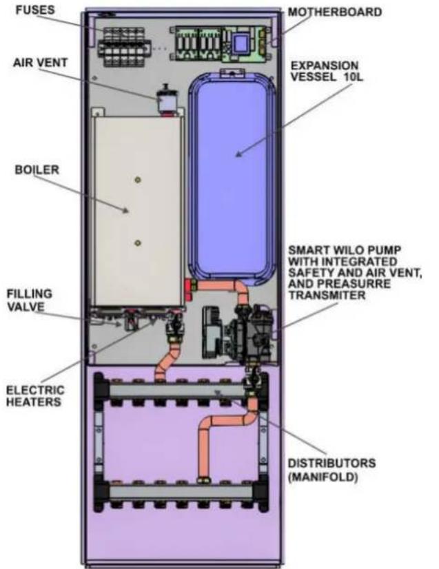
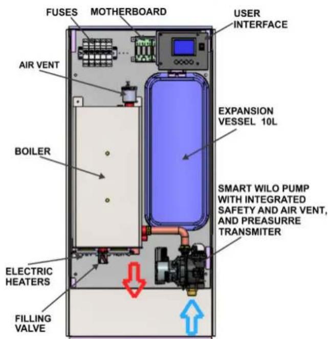
2.8 Product description
The eCompact Uz type electric boiler is a modern microprocessor controlled block boiler designed for centralized heating systems. The device is made using many years of experience in the production of electric boilers, using quality components from renowned domestic and international manufacturers, in compliance with the applicable European quality standards.
In addition to the elements of classical el. the boiler in its assembly contains: expansion dish, pump WILO PARA, safety valve, drain faucet, pressure and temperature sensor, automatic air vent, display with an overview of all system parameters.
2.9 Waste disposal
- Dispose packaging materials in ecologically sound manner
- Components that should be changed dispose in ecologically sound manner
2.10 Factory plate
Factory data plate is placed on the external side of the boiler and contains the following technical data: boiler type, batch / catalogue number, power, input power, maximum temperature, working pressure, water volume, mass, electric power supply, protection grade, manufacturer.
2.11 Dimensions
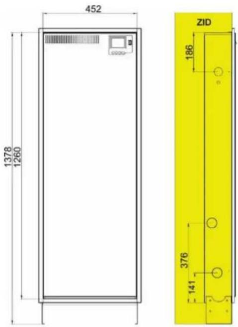
2.12 Delivery scope
When delivery the boiler stick to the following:
• Check if packaging is damaged during delivery
- Check if delivery is complete
| Part Pieces | |
| Boiler eCompact Uz | 1 |
| Instructions for handling | 1 |
2.13 Technical data
| Unit | eCompact 6 kW | eCompact 9 kW | eCompact 12 kW | eCompact 16 kW | |
| Power | kW | 6 | 9 | 12 | 16 |
| Usability level | % | 99 | 99 | 99 | 99 |
| Division of power grades | kW | 3×2 | 6×1,5 | 6×2 | 6×2,7 |
| Network voltage | V AC | 3N-400V/230V 50Hz | |||
| Protection level | IP20 | ||||
| Rated current for three phase connection | A | 3x8,7 | 3x13,1 | 3x17,4 | 3x23,2 |
| Rated current for single phase connection | A | 26,1 | 39,3 | ||
| Main fuses required for three-phase power supply | A | 3x16 | 3x25 | 3x25 | 3x32 |
| Main fuses required for mono-phase power supply | A | 1x32 | 1x50 | ||
| Minimum cable cross-section for three phase power supply | mm2 | 5×2,5 | 5×2,5 | 5×4 | 5×4 |
| Minimum cable cross-section for single phase power supply | mm2 | 3x4 | 3x6 | ||
| Safety valve | bar | 3 | |||
| Max allowed working pressure | bar | 2,6 | |||
| Min allowed working pressure | bar | 0,3 | |||
| Temperature range | °C | 10÷80 | |||
| Safety thermostat | °C | 95 | |||
| Boiler vessel volume | 9 | ||||
| Expansion vessel volume | 10 | ||||
| Connection of start line | DN20 (3/4") | ||||
| Connection of return line | DN20 (3/4") | ||||
| Device weight without and with manifold (without water) | Kg | 28/30 | 28/30 | 28/30 | 28/30 |
| Dimensions without and with manifold | mm | 957x452x132 / 1260x452x132(Visina x Širina x Dubina) | |||
| Microprocessor Unit | EK_CPU_1_3 | ||||
3. Transportation
NOTE: Transport damages
▶ Pay attention on instructions for transportation on packaging
▶ Use adequate transportation means, i.e. carts for bags with tighten strip. The product should be in horizontal position during transportation
▶ Avoid shocks or collisions
- Packed boiler put on carts for bags if needed secure it with strip and drive it to its mounting place
- Remove packaging
- Remove packaging materials and dispose it in ecologically acceptable manner
4. Installation of device
CAUTION: Human or material damages occurred because of irregular installation!
▶ Never install boiler without expansion dish (AG) and safety valve
▶ Boiler must not be installed in protective zone of important area or at the place of bath
NOTE: Material damage due to freezing!
▶ Boiler must be installed only in room safe of freezing
4.1 Be careful prior to assembly
NOTE: Material damage occurred due to incompliance with further instructions!
▶ Respect instructions for boiler and all installed components
Prior to installing take care of the following:
- All electrical connectors, protective measures and fusses should be done by professional person respecting all valid norms, regulations and local laws
- Electric connector should be done according to the connecting plans
• After corresponding installation of device execute grounding of the plant - Before opening device and all works turn off electric supply
- Non-professional and non-authorised attempts to connect device under voltage can produce material damage of device and hazardous electrical shocks
4.2 Distances
DANGER: Fire threat due to burnable materials and liquids!
▶ Do not dispose burnable materials and liquids close to the boiler
▶ Upoznajte korisnika s važećim propisima za minimalne razmake od lako zapaljivih materijala (poglavlje 2.7)
- Comply with regulations on electric installations and minimum distances in force in subject countries
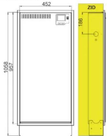
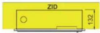
The total height of the boiler and thus the dimension of the installation opening depends on the choice of one of the 2 possible positions of the side supports of the boiler. The minimum height without divider is 957mm, and the maximum is 1057mm, while the minimum height with divider is 1260mm, and the maximum is 1360mm. According to the required space under the boiler for storing supply and return lines, one of the 2 possible positions of the support should be selected and thus define the dimension of the installation opening.
4.3 Boiler installation
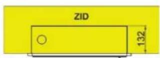
The eCompact Uz electric boiler is designed for wall mounting. The wall must be made of solid material, with a minimum thickness of 150 mm, and must not be mounted on plasterboard walls. Before installation, it is necessary to remove the front cover and the decorative frame from the boiler, as well as remove the mounting-bearing plate from the outer wall box, so that the installation can be performed correctly. First, the outer wall box is inserted into the installation hole, leveled and fixed, for which pur-foam can be used. The mounting plate is then inserted into the wall box and fastened with four screws. After the connection to the hydraulic and electrical installation is completed, the decorative frame and the front cover are returned to the boiler and their fitting to the wall is adjusted. When removing the front cover, it must be placed against the wall, in the immediate vicinity of the boiler, because there is a display with the corresponding cables on it. If the cables are disconnected due to pulling, it is necessary to return them to the appropriate places. Failure to do so may result in damage to the electronics.
natural_image
3D technical illustration of a modular appliance assembly with internal components and mounting brackets (no text or symbols)4.4 Connecting to a hydraulic network
The connection of this unit to the hydraulic system must be carried out by a qualified person - a qualified installer.
The appliances are equipped with a 10l / 1bar expansion vessel. Check that this volume is sufficient before mounting the unit. If this is not the case, then another expansion vessel of the required volume must be added to the hydraulic network. It is advisable to install valves on the inlet and outlet ports (DN 20) so that the boiler can be separated from the hydraulic network for easy maintenance or eventual service. The devices are equipped with a safety valve (3bar) integrated on the circulation pump. It is advisable to install a drainage pipe at the outlet of the safety valve and, with the fall from the boiler, to the drainage sy
4.5 Connecting to the electric network
The connection of this device to the electrical network must be carried out by a qualified electrician. The devices are designed for a 3 x 230 / 400V connection. The rated voltage of each phase must be 230V. Network voltages greater than 253V or less than 190V may interfere with the device. An electrical switch or appliance must be installed on the electrical installation, in accordance with the rules of fixed wiring, to ensure that the appliance is completely interrupted under Category III surge conditions.
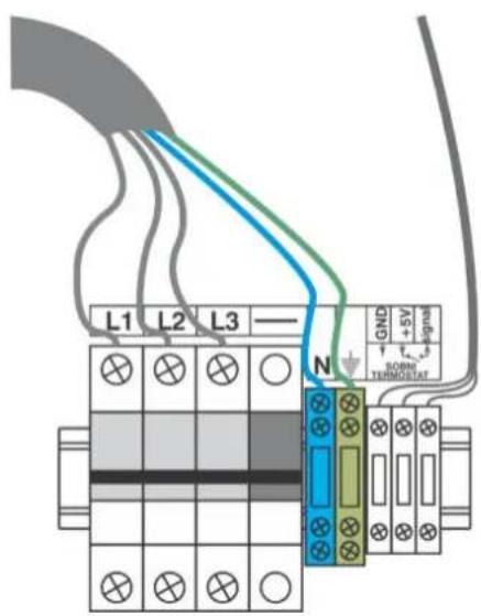
The power cable and the room thermostat cable can be inserted from the left or right side above the boiler vessel. The phase conductors are connected to the fuses and the neutral and protective conductors to the corresponding regular terminals next to the fuses. The remote voltage fuse is factory connected and nothing is connected to it. A three-pole automatic fuse with an upgraded remote voltage trigger, makes a safety circuit that, in addition to current protection, responds to thermal overload (signal from the safety thermostat that activates the voltage trigger) and switches off the boiler (all three phases) if the boiler overheats.
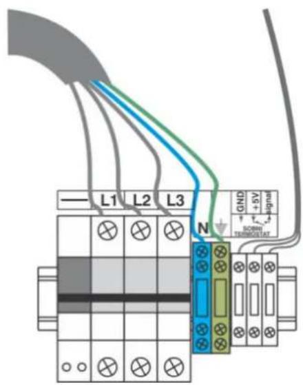
Scheme of boiler connecting on three-phase power supply NOARK fuses
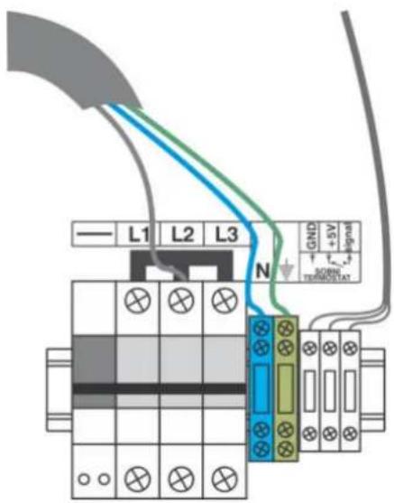
Scheme of boiler connecting on three-phase power supply ETI fuses
Scheme of boiler connecting to single-phase power supply – ONLY FOR POWER OF 6kW AND 9kW NOARK fuses

Scheme of boiler connecting to single-phase power supply – ONLY FOR POWER OF 6kW AND 9kW ETI fuses
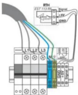
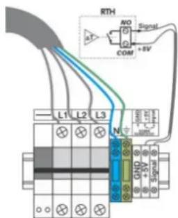
4.5.1 Connect the external control of the boiler (room thermostat)
The room thermostat connects to the regular clamps. It interrupts the 5V DC signal voltage coming from the boiler control panel. The EST 113 R5 is a precision electronic Mikotherm thermostat designed for these boilers, or use room thermostats with a voltage-free contact system, for example, digital thermostats with battery power.
THERMOSTATS THAT SUPPLY WITH 230V AC AND THOSE THAT VOLTAGE ON THE CONTACT SYSTEM OF THERMOSTATS SHOULD NOT BE USED.
4.6 Device Functions
The eCompact type electric boiler contains all the elements of a small boiler room, as well as many advanced features.
Temperature and hydraulic pressure sensors monitor changes in the system and send information to the microcontroller that processes and controls the operation of the boiler.
User communication with the device is facilitated and enhanced by displaying all system parameters on the graphical display and simple command with four keys. Normal operation of the unit requires a pressure in the cold system of 1.2 bar (+/- 0.4 bar). If the pressure is less than 0.8 bar, a warning message will be displayed and if it falls below 0.4 bar, the boiler will switch off with the fault information in the display. If the pressure is greater than 2.2 bar, a warning message will be displayed and if it exceeds 2.5 bar the boiler will switch off with fault information. If for some reason the pressure in the system exceeds 3 bar, the safety valve will react.
When the hydraulic system is properly pressurized, the boiler can operate normally in 2 modes. The first is the heating mode and the second is the frost protection system.
- Heating mode: Set the boiler power, which can be changed in the steps shown in the boiler power selection table. The microcontroller takes care of the symmetrical load of the phases, regardless of the set power, as well as the even load of the output relays and the heater. If necessary, the relays and heaters that have been on for a long time are switched off and the relays and heaters that have been inactive for a long time are switched on. In this way, the electrical grid is protected from phase asymmetry, and all boiler elements are evenly operated, thus increasing the service life of the unit. The operating temperature is set in steps of 1 degree C, and it is possible to set a value in the range of 10 - 80 degrees C. Switching the heater on and off is successive, with a interval of 3sec with a division of power into 3 groups of temperature shifted by 3 degrees each. The circulation pump switches on to the room thermostat control and also switches off to
the room thermostat control with an extended operation of 2 minutes due to heat transfer from the heater after switching off.
- Frost protection mode: In this mode the circulation pump is constantly switched on, the boiler power is fixed - 1/3 nominal and cannot be changed, and the operating temperature is also fixed 10 degrees C and cannot be changed. Room thermostat has no effect on operation. Activation of this mode is described in section 6.5.
The range of temperatures that can be set in normal heating mode is 10 to 80 degrees C. If the current temperature exceeds 80 degrees C, the boiler operates normally and the display indicates that the normal operating range has been exceeded. If the temperature exceeds 85 degrees C, all heaters are switched off, the pump runs continuously regardless of the room thermostat until the temperature returns to normal. If the temperature continues to rise, the safety thermostat reacts at 95 degrees C by giving the impulse to a remote voltage trigger, the safety circuit is activated, and the three-pole automatic fuses interrupt the full boiler power supply. In order for the boiler to continue operating, the fuses must be activated (raised) manually, which must be done by a service technician after repairing the fault that led to overheating. If the current temperature drops to 5 degrees C, the boiler is still operating normally but warning signs appear on the display, and if the temperature drops to 3 degrees C, the heater and the pump are not allowed, that is, the boiler is disabled when the system temperature is below 3 grade C, due to the risk of some part of the system being frozen
4.6.1 Heating pump air emission and de-blocking
Pump that exists in this device has automatic air vent so it is not necessary to perform any action about this.
4.6.2 Boiler and installation air emission
On the top plate of the boiler there is an air vent. This pot is automatic, so if you follow the rule of slow charging installation and boiler, additional manual venting will not be necessary.
4.7 Boiler power selection table
| Model | Nominal power | The step of adjus ng the set power | Selectable power |
| eCompact 6 | 6 kW | 2 kW | 0 kW; 2 kW; 4 kW; 6 kW |
| eCompact 9 | 9 kW | 1,5 kW | 0 kW; 1,5 kW; 3 kW; 4,5 kW; 6 kW; 7,5 kW; 9 kW |
| eCompact 12 | 12 kW | 2 kW | 0 kW; 2 kW; 4 kW; 6 kW; 8 kW; 10 kW; 12 kW |
| eCompact 16 | 16 kW | 2,7 kW | 0 kW; 2,7 kW; 5,4 kW; 8,1 kW; 10,8 kW; 13,5 kW; 16,2 kW |
5. Commissioning
When complete below described works fill in the Commissioning log (chapter 5.3).
5.1 Before commissioning

NOTE: Material damage occurred due to unprofessional operating!
Start-up without sufficient quantity of water destroys device
▶ Turn on the boiler and use it only if there is sufficient quantity of water

Boiler must work with minimum pressure of 0.7 bars
Before turn on, test if the following elements and joints are connector correctly and work correctly:
• Watertight of heating installation
- All pipes connected into ducts
• All electric connectors
5.2 First turn on

NOTE: Material damage due to incorrect handling!
▶ Instruct client/user how to handle device
- Prior to turn on check if heating installation is filled with water and air-vent
- Turn on the main switch (located on the control panel). Microcontroller need 10 seconds to process the information from the sensors and displays the values on the display
5.3 Commissioning log
- All parameters of the heating system and the unit itself will appear on the display
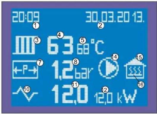
1 - Time;
2 - Date;
3 - Radiator symbol;
4 - Current system temperature;
5 - The temperature of the system;
7 - Pressure vessel symbol;
8 - Pressure in the system;
10 - Electric power symbol;
11 - Current boiler power;
12 - Default boiler output;
14 - Pump operation information: on-screen symbol - pump on;
15 - Heated space symbol (house)
16 - Room thermostat status information - If this symbol is on the display, the thermostat is on;
- After 3 minutes of the last key press, the display illumination is reduced to 10% of normal, and pressing any key returns to normal.
| 1. | Boiler type | |
| 2. | Serial number | |
| 3. | Set thermostat regulation | □ |
| 4. | Fill and discharge the air from the heating installation and check the impermeability of all connectors | □ |
| 5. | Establishing operating pressure | bar |
| Check the pressure of the expansion container | bar | |
| 6. | Test safety devices | □ |
| 7. | Set the electric connection according to local regulations | □ |
| 8. | Check of the functions of the device | □ |
| 9. | Users informed, technical documentation submitted | □ |
| 10. | Notes | |
| 11. | Confirmation of professional putting into operation | Seal of service technician / signature / date |
6. Setting the boiler operation
6.1 Symbols that may appear on display
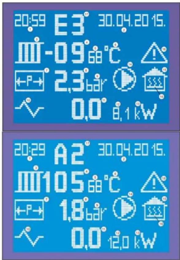
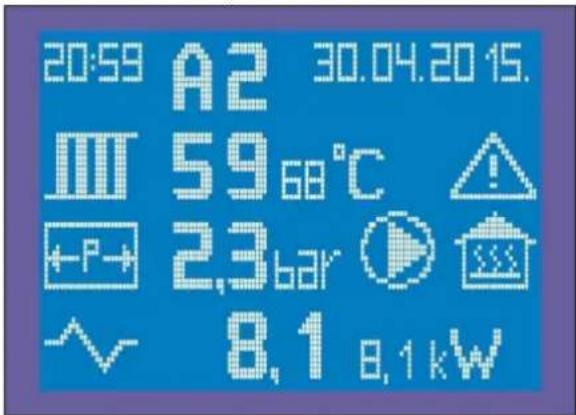
6.2 Warning symbols (codes)
A1 - warning: Approaching the lower limit of the allowed operating pressure (0.4 ÷ 0.8 bar)
A2 - warning: Approaching the upper limit of the allowed pressure (2.2 ÷ 2.6 bar)
A3 - warning: Approaching the lower limit of the allowed temperature (3 ÷ 5°C)
A4 - Approaching the upper limit of the allowed temperature (80 ÷ 85°C)
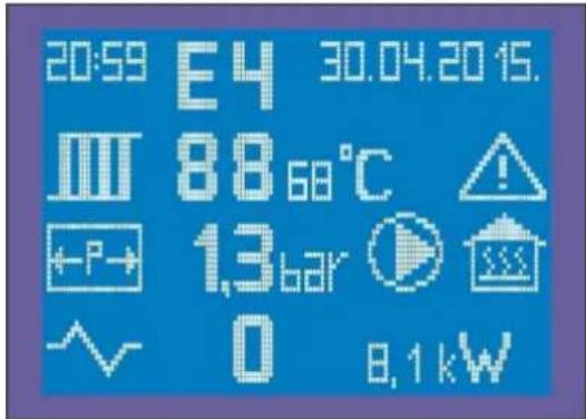
6.3 Error symbols (codes)
E0 - error: The set parameters are not with8in the limits (this situation is practically impossible if the eeprom is not empty and the boiler is switched on for the first time)
E1 - error: Pressure value below the lower limit (0.4 bar) ALL SWITCHED OFF
E2 - error: Pressure value above the upper limit (2.6 bar) ALL SWITCHED OFF
E3 - error: Temperature value of the boiler equal or bellow the lower limit (3°C) ALL SWITCHED OFF
E4 - error: Boiler temperature higher than the upper limit (85 °C) - HEATERS OFF, PUMP OPERATING CONTINUOUSLY
E5 - error: Temperature value of the boiler equal or bellow the lower limit (3°C) INFORMATIVE
E6 - error: Temperature sensor of the boiler in break or in short circuit ALL SWITCHED OFF
E7 - error: Temperature sensor in break or in short circuit ALL SWITCHED OFF
E8 - error: Sensor of the pressure in break or in short circuit ALL SWITCHED OFF
1 - Time
2 - Date
3 - Symbol of radiator (temperature of the system)
4 - Current temperature of the system (possible display from 99 to 99 °C)
5 - The set temperature of the system (possible display from 10 to 80 °C)
6 - Symbol of measuring unit of temperature (°C)
7 - The symbol of the container under pressure
8 - Pressure in the system (possible display from 0 to 3.6 bar with one decimal)
9 - Symbol of measuring unit of pressure (bar)
10 - Symbol of electricity
11 - Current power of the boiler in kW (display with one decimal)
12 - The set power of the boiler in kW (displayed with one decimal)
13 - Symbol of measuring unit of electricity (kW)
14 - Symbol of the circulation pump (appears only when the pump is switched on)
15 - Symbol of space that is heated (house)
16 - Symbol of switched on room thermostat
17 - Warning symbols (A0-A4) or error symbols (E0-E8)
18 - Symbol of danger (appears when the value of pressure or temperature exceeds the permitted limits)
6.4 Protection against impermissible pressure and temperature values
When the system pressure is less than 0.8 or greater than 2.2 bar the instantaneous pressure value is flashing, a warning sign (triangle) flashes and a warning code:
• A1 for operating pressure below 0.8 bar
• A2 for operating pressure above 2.2 bar
The boiler is still operating normally.
If the pressure value is below 0.4 bar or above 2.6 bar, the heaters and the pump are switched off (after 2 minutes) and the warning code goes into the error code:
• E1 for operating pressure below 0.4 bar
• E2 for operating pressure above 2.6 bar
In order for the boiler to continue operating, it is necessary to supplement the system to a pressure greater than or equal to 0.9 bar, or to reduce the pressure below 2.2 bar.
When the temperature in the system is less than 5^ C or greater than 80^ C, the current temperature value flashes, a warning sign (triangle) flashes and the warning code:
• A3 for temp. below 5°C
• A4 for temp. above 80°C
If the temperature drops below 3^ , the heaters and the pump are switched off (after 2 minutes) and the warning code goes into the error code:
• E3 for temperatures below 3°C
If the temperature rises above 85^ C, the heaters are switched off, the pump operates regardless of the room thermostat to reduce overheating, and the warning code goes into the fault code:
• E4 for temperatures above 85°C.
In order for the boiler to continue to operate, it is necessary to return the temperature to normal limits. If the program protection against overheating does not stop the temperature rise for some reason, a special safety thermostat at 95 °C will signal the protection circuit and the automatic fuses interrupt the power supply to the boiler. In order to continue operating, the fuses must be activated (raised) manually, which must be done by a service technician after repairing the fault that led to overheating.
6.5 Setting the operating mode
Press the SET key for 3 seconds to set the boiler mode. After that, the display will appear as in the picture
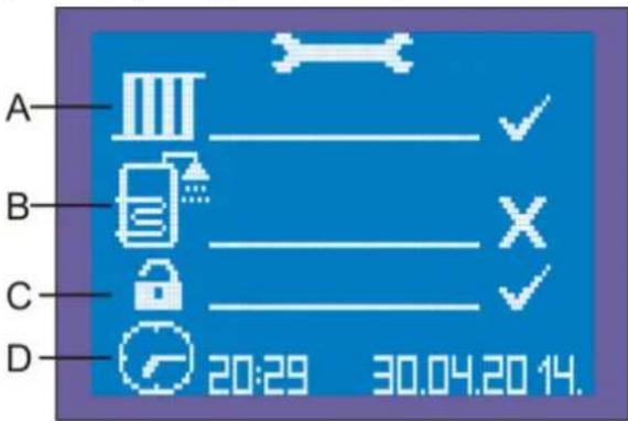
A) Heating mode symbol
Possible conditions: (X) OFF (√) ON
B) Symbol of the regime of sanitary water MUST BE (X) OFF
C) Choosing a level of safety at low temperatures Possible conditions:
√ PROGRAMMING - the boiler is not allowed to start and operate if the temperature T in it is lower than 3C
INSTALLATION IS FILLED WITH ANTI-FREEZER - It is allowed to start and operate the boiler even when T is lower than 3°C
FROST PROTECTION MODE
D) Clock symbol for setting time and date
The desired operating mode is selected by setting the flashing symbol with the □ and ▼ keys and confirming with the OK button, which then proceeds to the next setting item. In order for the setting to be accepted, it must be confirmed by pressing the SET key, which also exits the setting.
6.6 Description of operating mode
Only the heating mode shown in the picture should be selected in the settings. THIS IS A FACTORY SET BOILER OPERATION MODE. Otherwise checked may occur error indications E7 on the display.
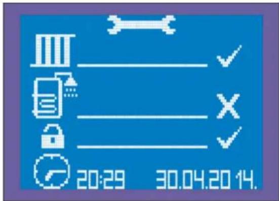
As already mentioned in item C), one of the two low temperature safety levels must be selected in the settings. The FACTORY SETTING value for C) is as in the picture, that is, it is not allowed to start and operate the boiler at temperatures below 3°C. Only if the system is filled with the proper glycol mixture can a second level of safety be activated, in which the boiler can be started and operated regardless of the danger of low temperatures.
In order for the setting to be accepted, it must be confirmed by pressing the SET button, thus exiting the setting corresponding to the selected boiler operating mode - HEATING ONLY.
6.7 Setting the heating parameter
6.7.1 Setting the default boiler temperature
To set the default boiler temperature and power, briefly press the SET key. The set temperature starts flashing and can be adjusted using the ▲ and ▼ buttons. Each time you press one of the keys, the temperature is increased or decreased by 1°C. 10°C to 80°C values can be selected.
6.7.2 Setting the default boiler power
After setting the temperature, pressing the OK button switches to the setting the default boiler power whose value starts flashing. Each key press ▲either ▼increases or decreases the set power by one power step. If it is only necessary to change the power and not the temperature, when the temperature value flashes press OK and thus goes to the boiler power setting. In order for the setting to be accepted, it must be confirmed by pressing the SET key. If the changes are not confirmed, after 15 seconds of pressing any button (except SET), the controller resumes operation according to the old setpoint value and exits the adjustment mode. Once the parameter values have been set in this mode, the microprocessor remembers until the setting switches off the heating in the mode menu. In the next setting, in the operating mode menu, when the heating is switched on, the set temperature and heating power must be set.
6.8 Room thermostat
If a room thermostat is used, it must be installed in the reference room. The temperature control of all rooms heated by the system is via this remote control. Radiators in the reference room must not be equipped with thermostatic valves or they must always be OPEN. All radiators in other rooms must be fitted with thermostatic valves.
6.9 Termination of the work of the heating system
In case of short-term interruption of the heating operation, the boiler temperature must be lowered by means of a thermostatic boiler controller. To prevent the installation of the heating system from freezing, the room thermostat temperature must not be set below 7 °C. The boiler must be switched off when the heating operation is interrupted for a long time
6.10 Switching off the boiler

WARNING! Material damage from frost! If the heating system is inoperative, freezing may occur at low temperatures
▶ Protect the heating system from freezing
▶ If there is a risk of frost and the boiler is not functioning, empty the complete installation
- Set the main switch on the control panel to "0" (off)
- Protect the heating system from freezing. Completely empty all water pipes.
7. Possible problems, causes and measures to be taken
| PROBLEM | CAUSE | MEASURE |
| The boiler does not react after switching on the main switch | Boiler is disconnected from electricityThe fuses on the bottom panel are switched offPossible disappearance of the control phaseFault of the main switch ON/OFF | Ensure power supply voltageSwitch on the fusesCheck on the fuses if there are all three phases at the exitReplace the defective part |
| The circulation pump does not operate when the main switch and the room thermostat are switched on | Defective room thermostatMechanically blocked impeller of the circulation pumpDefective circulation pump | Replace room thermostatUnblock the circulation pump impellerReplace the circulation pump |
| The boiler does not heat or does not heat enough / the heating pump works | Lack of 1 or 2 phasesThe power of the boiler is too lowFault in one of the relaysFault in one of the heaters | Check if all three phases come into the boilerCheck the set power of the boiler.Replace the defective part |
| The boiler heats up but quickly shuts off. It reaches a set temperature quickly but the radiators are cold | Closed valve under boilerMechanically blocked impeller of the circulation pumpDefective circulation pump | Open the valve under the boilerUnlock the impeller of the circulation pumpReplace the circulation pump |
| Large oscillations of working pressure | Closed valve under boilerInsufficient pressure in expansion vesselDefective expansion vessel | Open the valve under the boilerCheck the pressure in the expansion vessel and, if necessary, inflate the vessel on the appropriate valueReplace the expansion vessel |
8. Pump
8.1 Pump Wilo-Para MSL/6-43SC
Wilo Para MSL / 6-43 / SC is a circulating pump for heating systems, heating systems for family houses and other similar systems. The most important characteristics of this pump are:
• Maximum flow rate: 2.1 m3 / h
• Maximum water column height: 6.8 m
• Maximum media temperature (at ambient temperature 58^ C): 100^ C
• Maximum glycol concentration in the system: 50%
• Minimum and maximum rotor speed: 2430 \~ 4300 rpm
• Minimum and maximum pump power: 3 W \~ 43W
- Minimum and maximum pump current (230V AC): 0.044 0.44A
- Energy Efficiency Index (EEI): ≤ 0.2 (This energy efficiency index in practice means that the Wilo-Para pump consumes up to 80% less electricity compared to earlier versions of the same class pumps that did not have electronic power regulation).
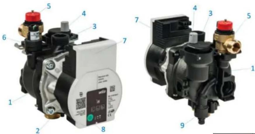
- Composite OEM pump housing
- Pump inlet MS 34 'SN
- Pump output terminal composite 34 " SN
- Automatic air vent
- Safety valve 3bar
- Pressure sensor
- Pump head with electronics
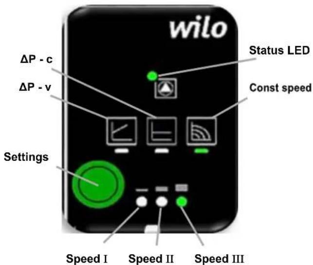
- Pump Mode Selector Button (settings)
- Drain faucet
| LED display | Control mode | Pump curve | |
| 1. | Constant speed | II | |
| 2. | Constant speed | I | |
| 3. | Variable differential pressure Δp-v | III | |
| 4. | Variable differential pressure Δp-v | II | |
| 5. | Variable differential pressure Δp-v | I | |
| 6. | Constant differential pressure Δp-c | III | |
| 7. | Constant differential pressure Δp-c | II | |
| 8. | Constant differential pressure Δp-c | I | |
| 9. | Constant speed | III |
Faults, causes and remedies
The troubleshooting must only be carried out by a qualified specialist, and work on the electrical connection must only be carried out by a qualified electrician.
| Faults | Causes | Remedy |
| Pump is not running although the power supply is switched on | Electrical fuse defective | Check fuses |
| No voltage supply at pump | Rectify the power interruption | |
| Noisy pump | Cavitation due to insufficient suction pressure | Increase the system pressure within the permissible range |
| Check the delivery head and set it to a lower head if necessary | ||
| Building does not warm up | Thermal output of the heating surfaces is too low | Increase setpoint |
| Change the control mode from Δp-c to Δp-v |
Fault signals
• The fault signal LED indicates a fault.
- The pump switches off (depending on the fault) an attempts a cyclical restart.
| LED | Faults | Causes | Remedy |
| Lights up red | Blocking | Rotor blocked | Activate manual restart or contact customer service |
| Contacting/ winding | Winding defective | ||
| Flashes red | Under/overvoltage | Power supply too low/high on mains side | Check mains voltage and operating conditions, and request customer service |
| Excessive module temperature | Module interior too warm | ||
| Short-circuit | Motor current too high | ||
| Flashes red/ green | Generator operation | Water is flowing through the pump hydraulics, but there is no mains voltage at the pump | Check the mains voltage, water quantity/pressure and the ambient conditions |
| Dry run | Air in the pump | ||
| Overload | Sluggish motor, pump is operated outside of its specifications (e.g. high module temperature). The speed is lower than during normal operation. |
Activating factory setting
The factory setting is activated by pressing and holding the operating button whilst switching off the pump.
- Press and hold the operating button for atleast 4 seconds.
- All LEDs flash for 1 second.
• The LEDs for the last setting flash for 1 second.
Decommissioning
Shutting down the pump
Shut down the pump immediately if the connecting cable or other electrical components are damaged.
- Disconnect the pump from the power supply.
- Contact a service technician.
Maintenance
Cleaning
- Carefully remove dirt from the pump on a regular basis using a dry duster.
- Never use liquids or aggressive cleaning agents.
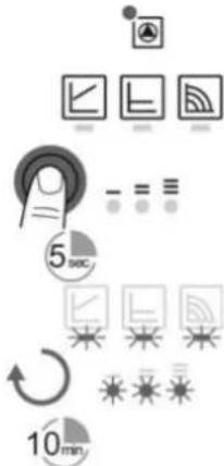
Manual restart
- The pump attempts an automatic restart upon detecting a blockage.
If the pump does not restart automatically: - Activate manual restart via the operating button: press and hold for 5 seconds, then release.
- The restart function is initiated, and lasts max. 10 minutes.
- The LEDs flash in succession clockwise.
- To cancel, press and hold the operating button for 5 seconds.
If the fault cannot be remedied, contact an authorized service center.

NOTICE
After the restart, the LED display shows the previously set values of the pump.
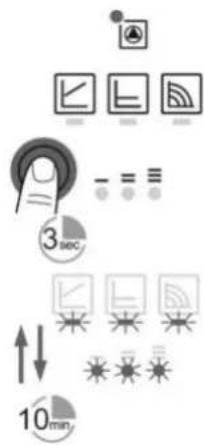
Venting
- Fill and vent the system correctly.
If the pump does not vent automatically: - Activate the pump venting function via the operating button:
Press and hold for 3 seconds, then release. The pump venting function is initiated and lasts 10 minutes.
The top and bottom LED rows flash in turn at 1 second intervals. - To cancel, press and hold the operating button for 3 seconds.

NOTICE
After venting, the LED display shows the previously set values of the pump.
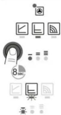
Lock/unlock the button
- To activate the key lock, press and hold the operating button for 8 seconds until the LEDs for the selected setting briefly flash, then release.
- LEDs flash constantly at 1-second intervals.
- The key lock is activated: pump settings can no longer be changed.
- The key lock is deactivated in the same manner as it is activated.

NOTICE
All settings/displays are retained if the power supply is interrupted.
9. Product data sheet (in accordance with EU regulation no. 811/2013)
| 1. | Manufacturer | MIKOTERM DOO | |
| 2. | Brand name | eCompact Uz | |
| 3. | Models | I | eCompact Uz 6kW |
| II | eCompact Uz 9kW | ||
| III | eCompact Uz 12kW | ||
| IV | eCompact Uz 16kW |
| I | II | III | IV | ||||
| 4. | Room heating: Seasonal energy-efficiency class | D | D | D | D | ||
| 5. | Room heating: Nominal heat output(*8) (*11) | P_rated | kW | 6 | 9 | 12 | 16 |
| 6. | Room heating: Seasonal energy efficiency(*8) | ns | % | 37,43 | 37,62 | 37,72 | 37,79 |
| 7. | Annual energy consumption(*8) | QHE | kWh | 6600 | 11022 | 13266 | 18688 |
| 8. | Sound power level, indoor | LWA indoor | dB(A) | 32 | 32 | 32 | 32 |
| 9. |  All specific precautions for assembly, installation and maintenance are described in the operating and installation instructions. Read and follow the operating and installation instructions. All specific precautions for assembly, installation and maintenance are described in the operating and installation instructions. Read and follow the operating and installation instructions. | ||||||
| 10. |  All of the data that is included in the product information was determined by applying the specifications of the relevant European directives.Differences to product information listed elsewhere may result in different test conditions. Only the data that is contained in this product information is applicable and valid. All of the data that is included in the product information was determined by applying the specifications of the relevant European directives.Differences to product information listed elsewhere may result in different test conditions. Only the data that is contained in this product information is applicable and valid. | ||||||
(*8) For average climatic conditions
(*11) For boilers and combination boilers with a heat pump, the nominal heat output "Prated" is the same as the design load in heating mode "Pdesignh", and the nominal heat output for an auxiliary boiler "Psup" is the same as the additional heating output "sup(Tj)"
MIKOTERM DOO
Serbia, Bul.Sv. cara Konstantina 82 18000 Niš
00 381 18 4542002 / 3409702 / 3409703
www.mikoterm.com
office@mikoterm.com
This document is the property of MIKOTERM d.o.o. and any duplica on and copying thereof is punishable by law. The contents of technical documenta on and technical solu ons from this manual are protected by intellectual property of MIKOTERM d.o.o. Any unauthorized use, copying or publica on, in whole or in part, by other en es without the authoriza on of MIKOTERM d.o.o. is punishable by law.
Niš, 2022.
Mikoterm d.o.o. does not assume responsibility for possible errors in this booklet produced by printing or duplica on, all images and schemes are in principle, it is necessary to adapt each to the actual situa on on the ground. In any case, Mikoterm reserves the right to make changes that it deems necessary on its products.