eTK 6÷36kW - Central heating boiler Mikoterm - Free user manual and instructions
Find the device manual for free eTK 6÷36kW Mikoterm in PDF.


| Product Type | Central Heating Boiler |
| Brand | Mikoterm |
| Model | eTK 6÷36kW |
| Power Range | 6 to 36 kW |
| Fuel Type | Electric |
| Voltage | 230V / 400V (3-phase) depending on configuration |
| Frequency | 50 Hz |
| Dimensions (H x W x D) | Approx. 900 x 500 x 600 mm |
| Weight | Approx. 60 kg |
| Heating Output | Adjustable from 6 kW to 36 kW |
| Efficiency | Up to 99% (electric) |
| Control Type | Digital thermostat with programmable timer |
| Safety Features | Overheat protection, pressure relief valve, anti-freeze function |
| Installation Type | Wall-mounted or floor-standing |
| Suitable For | Residential and small commercial heating systems |
| Nominal Pressure | 3 bar (max) |
| Water Capacity | Approx. 5 liters |
| Maintenance | Periodic cleaning of filters and heating elements; check safety valves annually |
| Spare Parts Availability | Available from Mikoterm authorized service centers |
| Reparability | Modular design allows easy replacement of heating elements and control board |
| Warranty | 2 years (standard) |
Frequently Asked Questions - eTK 6÷36kW Mikoterm
User questions about eTK 6÷36kW Mikoterm
0 question about this device. Answer the ones you know or ask your own.
Ask a new question about this device
Download the instructions for your Central heating boiler in PDF format for free! Find your manual eTK 6÷36kW - Mikoterm and take your electronic device back in hand. On this page are published all the documents necessary for the use of your device. eTK 6÷36kW by Mikoterm.
USER MANUAL eTK 6÷36kW Mikoterm
Guidebook for installa on, handling and maintenance – ENG
eTK 6÷36kW
Electric block-boiler for heating systems with thermoregulatory microprocessor
Content
1. Description of symbols and instructions for safe work
2. Device data
2.1 Typology
2.1.1 Statement on compliance
2.1.2 Regular application
2.2 Instructions for mounting
2.3 Instructions for work
2.4 Anti-frost protection and inhibitors
2.5 Norms, regulations and standards
2.6 Tools, materials and auxiliary measures
2.7 Minimum distances and Inflammability of construction materials
2.8 Product description
2.9 Waste disposal
2.10 Scope of delivery
2.11 Factory data plate
2.12 Dimensions and technical data
2.12.1 Dimensions and technical data for boiler eTK
2.12.2 Technical data
3. Transportation
4. Device installing
4.1 Warnings before mounting
4.2 Distances
4.3 De-mounting of front casing
4.4 Boiler mounting
4.5 Hydraulic connections testing
4.6 Systems on which the Boiler can be connected
4.7 Installation filling with water and waterproof testing
4.7.1 Filling the boiler with water and testing sealing
4.7.2 Heating pump air emission and de-blocking
4.7.3 Boiler and installation air emission
5. Electrical connection
5.1 Positions of introducer for the introduction of the power cable
5.2 Connecting power (voltage) cable
5.3 Scheme for connecting power (voltage) cable
5.4 Connect boiler's external control (room thermostat)
5.5 Electrical schemes
6. Commissioning
6.1 Before commissioning
6.2 First start
6.3 Start-up log
7. Handling heating installation
7.1 Instruction for work
7.2 Overview of the elements to adjust
7.2.1 Device functions
7.2.2 Basic settings
7.3 Regulation of heating
7.3.1 Boiler temperature adjustment
7.3.2 Boiler power adjustment
7.3.3 Warnings for low temperature
7.3.4 Warnings for high temperature
7.3.5 Warning symbols and codes
7.3.6 Room temperature thermostat
7.3.7 Interruption of heating
7.4 Putting the boiler out of drive
8. Cleaning and maintenance
8.1 Boiler heating
8.2 Check the working pressure; add the water and air-vent installations
8.3 Add the water and vent installation
8.4 Inspection and maintenance log
9. Environment protection / Waste disposal
10. Troubles and troubleshooting
11. Product data sheet (in accordance with EU regulation no. 811/2013)
1. Description of symbols and instructions for safe work
1.1 Description of symbols
Warnings

Warnings in text are marked by gray triangle, background warnings are framed

Electric shock danger is marked by lightning symbol in warning triangle
The signal words at the beginning of the warning mean the way and level of consequences if protective measures are not applied
- NOTE means that smaller material damages may occur
- CAUTION means that smaller to middle injuries may occur
- WARNING means that heavy injuries may occur
• DANGER means that heavy injuries may occur
Important information

Important information, meaning no danger for people and things, are marked by the symbol displayed in the following text. These are limited by lines, above and below the text
Further symbols
| Symbol | Meaning |
| ▶ | Action step |
| → | Directives to other places in document or to other documents |
| • | Enumeration /Entry from the list |
| – | Enumeration /Entry from the list (2.) |
Table 1
1.2 Instructions for safe work
General safety instructions
Non-compliance with safety instructions may cause heavy injuries – or lethal outcomes and material damages and environment pollution.
- Electrical installation should be examined by an expert prior to the device assembly.
- All electric works should be performed by authorised person in accordance with corresponding regulations.
- Commissioning and maintenance and repairs should be done by authorised service only.
- Technical acceptance of installations should be performed in accordance with corresponding regulations.
Danger because of disrespecting security rules in alert situations, for example fire.
- Never expose your-self to life danger. Own security always has priority.
Damage occurred because of wrong handling
Wrong handling may lead to injuries of persons and/or installation damage.
- Make sure that device is available only to professionals.
- Installation and commissioning, and maintenance and repair, must be done only by service authorised for electrical works.
Installation and commissioning
- Placement of device can be done only by authorised service.
- Boiler can be turned on only if installation is with corresponding pressure level and working pressure regular.
- Do not close security valves in order to avoid damage caused by too high pressure. During warming water can leak on security valve of the hot water circuit and hot water pipes.
- Install this device only in the room where freezing is not possible to occur.
- Do not store or dispose inflammable materials or liquids in the vicinity of this device.
- Keep safe distance in accordance with valid regulations.
Life threat of electric power shock
- Secure electric power connecting is done by authorised service! Comply with connecting scheme
- Prior to any work: turn off electric power supply. Secure against accidental turn on.
- Do not mount this device in moist rooms
Control examination / Maintenance
- Recommendation for user: conclude agreement on maintenance with authorised service to perform annual maintenance and controlling examinations
- User is responsible for safety and environmental acceptance of the installation
- Comply with safety work instruction as given in the chapter Cleaning and Maintenance
Authentic spare parts
There shall not be undertaken any responsibility for damage occurred due to spare parts not delivered by the manufacturer
• Use only original spare parts
Material damages due to freezing
- When there is damage due to freezing drain water from the boiler, tank and pipelines for heating. Danger of freezing does not exist only when entire installation is dry
Instructions for service
- Inform users about mode of work of device and instruct them in maintenance
- Inform users not to perform any modifications or repair on their own
- Warn users that children cannot stay near heating installations
- Fill in and submit Commissioning log and Handover log attached in this document
• Deliver technical documentation to the user
Waste disposal
- Dispose packaging materials in ecologically Acceptable manner
- Secure device in ecologically acceptable manner and in authorised place
Cleaning
• Clean outside of device with wet cloth
2. Device data
These instructions contain important information about safe and professional assembly, commissioning and maintenance of the boiler.
These instructions are for installers who have knowledge for work with heating installations due to their professionalism and experience.
2.1 Typology
These instructions are related to the following kind of device:
eTK
6÷36kW
2.1.1 Statement on compliances
We hereby state that devices are tested in accordance with the following directives: 2014/35/EU (low voltage directive, LVD) and 2014/30/EU (electro-magnetic compatibility directive, EMC).
2.1.2 Regular application
The boiler can be used only for heating the water for heating system and for indirect use of hot water. To ensure correct use it is mandatory to comply with instructions for handling, data on the factory plate and technical data.
2.2 Instructions for mounting

Use only original spare parts of the manufacturer or spare parts approved by the manufacturer. There shall not be any responsibility for damages caused by spare parts which have not been delivered by the manufacturer
When mounting heating installations keep with the following instructions:
- Valid regulations in construction industry
- Regulations and norms on safety-technical equipment of heating installations
- Changes on the place of mounting according to valid regulations propisima
2.3 Instructions for work
When working with heating installation follow next instructions:
▶ Boiler should work in working range up to max temperature of 80 °C and min pressure of 0.5bar to max pressure of 3.0bar, which should be controlled on regular basis
▶ Boiler should be handled only by adults who are familiar with instructions and work of the boiler
▶ Do not close safety valve
▶ Inflammatory objects must not be put on the boiler surface or close to it (within safety distance)
▶ Boiler surface clean only with non-inflammatory products
▶ Inflammatory substances do not keep in the room for boiler installation (e.g. petroleum, oil, etc.)
▶ During the work no one lid must be open
▶ Keep safe distance in accordance with regulations
2.4 Inhibitors and anti-frost products
It is not allowed to use protective products against frost neither inhibitors. Id it is not possible to avoid anti-frost protection then should use anti-frost products allowed for heating installations.

Anti-frost products:
▶ Reduce lifetime of the boiler and its parts
▶ Reduce heat transmission
2.5 Norms, regulations and standards
This product is in compliance with the following regulations:
- EN 50110-1:2013 – Operation of electrical installations - Part 1: General requirements
- EN 55014-1:2017; EN 55014-2:2015 – Electromagnetic compatibility - Requirements for household appliances, electric tools and similar apparatus - Part 1: Emission - Part 2: Immunity - Product family standard
• EN 60335-1:2016 Household and similar electrical appliances - Safety - Part 1: General requirements - EN 61000-3-2:2019 Electromagnetic compatibility (EMC) - Part 3-2: Limits - Limits for harmonic current emissions
- EN 61000-3-3:2014/A1:2020 Electromagnetic compatibility (EMC) - Part 3-3: Limits - Limitation of voltage changes, voltage fluctuations and flicker in public low-voltage supply systems
2.6 Tools, materials and auxiliary measures
Standard tools for heating installations, water supply and electric-installations are needed for mounting and maintenance of the boiler.
2.7 Minimum distances and burnable construction materials
Depending on valid regulations, other minimum distances could be applied, different than mentioned below.
▶ Comply with regulations of electrical installations and minimum distances which are in force in the subject country
▶ Minimum distance for heavy inflammable and self-extinguishing materials is 200 mm
Inflammability of components
| A | Non-inflammable | |
| A1: | Non-inflammable | Asbestos, stone, wall tiles, baked clay, plaster (with no organic additives) |
| A2: | With smaller quantity of added elements (organic components) | Plaster cardboards plates, base felt, glass fibres, plates of ACUMIN, ISOMIN, RAIOT, LOGNOS, VELOX, AND HERACLITUS |
| B | Inflammable | |
| B1: | Normally inflammable | Beech, oak, veneered wood, felt, HOBREX, VERSALIT and UMAKART plates |
| B2: | Normally inflammable | Pine, larch and spruce, veneered wood |
| B3: | Inflammable | Asphalt, cardboard, cellulose materials, tar-paper, plywood plates, cork plates, polyurethane, polystyrene, polyethylene, floor fibre materials |
Table 2: Ignitable materials and composition of elements according to DIN 4102
2.8 Product description
Basic components of boiler:
- Boiler body
• Device frame and casing - Control unit
- Contactors (switches)
• Safety circuit (automatic fuses with trigger) - Processor board and boiler electronics
• Water pressure sensor - Safety valve
Boiler can be installed as integral part of the central heating system, floor heating, hybrid, or accumulation systems
Boiler is compounded of weld housing of steel tin with thermal insulation. The boiler is fixed on the wall by supplied mounting set. Installed heating insulation in boiler jacket reduces loss of the heat, and also protects against noise
Safety elements (vent valve, managing surface fuse and temperature safety limitation) are mounted at the top of boiler.
Depending on the type of the boiler, different elements of heating are used. Heating elements' performance can be adjusted according to grades.
Different performance grades sets can be obtained through control panel. Number and division of performance grades are visible from technical data (see chapter 2.12.2).
1 IN Return boiler's line
2 OUT Start boiler's line
3 Boiler's exchanger
4 Electric heaters
5 Safety assembly for connecting the power cord
6 Terminals for connection, neutral (N) and protective (PE) lines
7 Connection 12 " UN
8 Terminal for room thermostat
9 Microprocessor plate LCTR2
10 Electric heater contactors
11 Temperature sensor
12 Safety thermostat (STB)
13 Control panel with display LCl2
14 Power switch (ON/OFF)
15 Power cable input

Image 1: Open device view
2.9 Waste disposal
- Dispose packaging materials in ecologically sound manner
- Components that should be changed dispose in ecologically sound manner
2.10 Delivery scope
When delivery the boiler stick to the following:
- Check if packaging is damaged during delivery
- Check if delivery is complete
| Part Pieces | |
| Boiler eTK | 1 |
| Assembly Set | 1 |
| Instructions for handling | 1 |
2.11 Factory plate
Factory data plate is placed on the external side of the boiler and contains the following technical data:
- Boiler type
- Batch / Catalogue number
- Power
- Input power
• Maximum temperature - Working pressure
- Water volume
- Mass
• Electric power supply - Protection grade
- Manufacturer
2.12 Dimensions and technical data
2.12.1 Dimensions and technical data for boiler eTK
eTK 6÷24kW
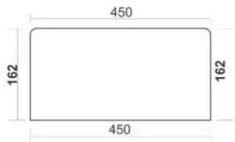
eTK 30÷36kW


Image 2: Dimensions eTK 6÷24kW and 30÷36kW
2.12.2 Technical data
| Jedinica | eTK 6kW | eTK 9kW | eTK 12kW | eTK 18kW | eTK 24kW | eTK 30kW | eTK 36kW | |
| Power | kW | 6 | 9 | 12 | 18 | 24 | 30 | 36 |
| Usability level | % | 99 | 99 | 99 | 99 | 99 | 99 | 99 |
| Number of power grades | 3 | 3 | 3 | 3 | 3 | 3 | 3 | |
| Division of power grades | kW | 3×2 | 3×3 | 3×4 | 3×6 | 3×8 | 3×10 | 3×12 |
| Network voltage | V AC | 3N ~ 400/230V 50Hz | ||||||
| Ingress Protection rating | IP20 | |||||||
| Dimensions | HxLxW | 600×450×162 | 600×450×215 | |||||
| Needed fuses for three phase supply voltage | A | 3×16 | 3×20 | 3×25 | 3×32 | 3×40 | 3×50 | 3×63 |
| Minimum cable cross-section for three phase power supply | mm2 | 5×2,5 | 5×2,5 | 5×4 | 5×4 | 5×6 | 5×10 | 5×10 |
| Needed fuses for single phase supply voltage | A | 1×32 | 1×50 | - | - | - | - | - |
| Minimum cable cross-section for single phase power supply | mm2 | 3×4 | 3×6 | - | - | - | - | - |
| Water volume in boiler | 14,2 | 21 | ||||||
| Max allowed working pressure | bar | 3 | ||||||
| Min allowed working pressure | bar | 0,5 | ||||||
| Temperature range | °C | 10÷80 | ||||||
| Safety thermostat | °C | 95 | ||||||
| Connection of start line | 1" SN (DN25) | |||||||
| Connection of return line | 1" SN (DN25) | |||||||
| Device mass (without water) | Kg | 12 | 12,7 | 13,5 | 13,5 | 13,5 | 17,2 | 17,2 |
| Microprocessor Unit | EK_CPU_LCTR2 / LCI2 | |||||||
Table 3: Technical data of Device
Important: if connec ng to mono phase power please consult technical person about technical issues.
3. Transportation

NOTE: Transport damages
▶ Pay attention on instructions for transportation on packaging
▶ Use adequate transportation means, i.e. carts for bags with tighten strip. The product should be in horizontal position during transportation
▶ Avoid shocks or collisions
- Packed boiler put on carts for bags if needed secure it with strip and drive it to its mounting place
- Remove packaging
- Remove packaging materials and dispose it in ecologically acceptable manner
4. Installation of device

CAUTION: Human or material damages occurred because of irregular installation!
▶ Never install boiler without expansion dish (AG) and safety valve
▶ Boiler must not be installed in protective zone of important area or at the place of bath

NOTE: Material damage due to freezing!
▶ Boiler must be installed only in room safe of freezing
4.1 Be careful prior to assembly

NOTE: Material damage occurred due to incompliance with further instructions!
▶ Respect instructions for boiler and all installed components
Prior to installing take care of the following:
- All electrical connectors, protective measures and fusses should be done by professional person respecting all valid norms, regulations and local laws
• Electric connector should be done according to the connecting plans
• After corresponding installation of device execute grounding of the plant - Before opening device and all works turn off electric supply
- Non-professional and non-authorised attempts to connect device under voltage can produce material damage of device and hazardous electrical shocks
4.2 Distances

DANGER: Fire threat due to burnable materials and liquids!
▶ Do not dispose burnable materials and liquids close to the boiler
▶ Let know the user the valid regulations for minimum distances from burnable materials (section 2.7)
- Comply with regulations on electric installations and minimum distances in force in subject countries
- Place boiler on the wall in such manner to leave free space as illustrated in the Image 3

Image 3 : Minimum distance during installation
$$ A = 5 0 0 \mathrm{mm} / B = 5 0 \mathrm{mm} / C = 2 0 0 \mathrm{mm} / D = 5 0 0 \mathrm{mm} $$
4.3 Demounting front boiler casing
Boiler casing can be removed for simple handling and installation (image 4)
▶ Unscrew 3 bolts at top lid
▶ Unscrew 3 bolts at bottom lid
▶ With slow pulling toward you demount front casing of the boiler
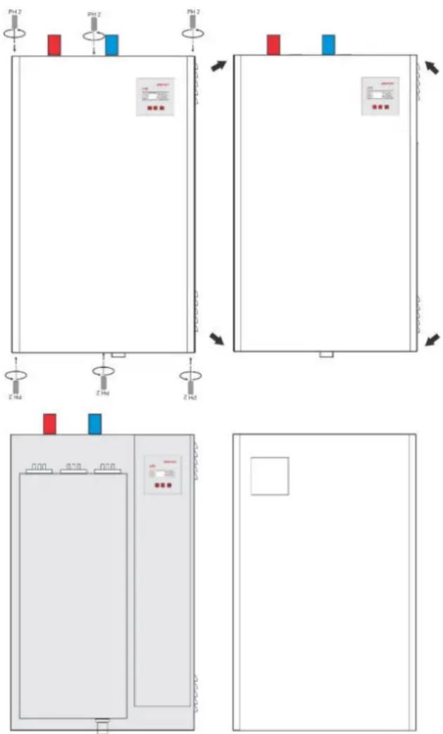
Image 4 : Opening the boiler (Demounting front casing)
4.4 Mounting boiler

NOTE: Material damage occurred by irregular installation on the wall!
It is necessary to use proper material for fixing
This chapter describes boiler mounting on the wall
- Draw position of drilling holes for mounting set respecting minimum distances (image 3)
- Drill holes upon dimensions given in (image 2)
- Put into drilled holes plastic dowel enclosed in device packaging (or adequate dowel for unusual kind of wall)
- Then screw bolts into delivered dowels (or other) in such way that are left out from the wall min 5 mm-max 10mm
- Carefully hang device on the wall
• Make sure that boiler is placed vertically - Fixed boiler on the wall by mounting set and screw
4.5 Hydraulic attachments execution

NOTE: Material damages caused by permeable connections!
▶ Attachment duct lines install without connecting on boiler connections
Heating duct lines connect as follows:
▶ Connect return line on connection IN
▶ Connect start line on connection OUT
4.6 Systems on which the eTK boiler can be connected
- All systems for heating the space designed for 80/60 temperature regime (or lower)
- Closed heating systems
- Systems with boiler on solid fuel

ATTENTION! When connecting the boiler to a solid fuel boiler system, where the same pump is used for both boilers, the pump should be electrically connected according to the connection diagram given in section 5.3. This ensures that the pump for both boilers is switched on correctly.
Excessive temperature stresses of the boiler are possible, as well as damage to the heater, seals and boiler vessel.
- It can be used as heating device for water in accumulating boilers over exchanger.
- It can also be used in certain technological processes providing that there is no need for water temperature higher than 60°C.
- It must not be used for direct heating of domestic hot water.
4.7 Filling the installations and watertight testing

The eTK boiler does not contain a manometer, so when filling the installation with water, the pressure must be monitored on the manometer installed on the heating installation
4.7.1 Filling the boiler with heating water and sealing test
Waterproof should be tested prior to put on the boiler.

DANGER: Injuries and/or material damages can occur with overpressure when testing watertight!
High pressure can damage regulatory and safety devices and reservoir.
▶ After filling with water set the boiler on pressure that is equal to the opening pressure of safety valve
▶ Comply with maximum pressure of installed components
▶ After testing sealing, open again closing valves
▶ Make sure that all pressures, regulatory and safety parts work correctly

DANGER: Health threat due to mix of drinking water!
It is demanding to respect state norms and regulations on avoiding mix drinking water (with water from heating installations)
▶ Comply with EN 1717

NOTE: Installation damage due to bad quality of water! Heating installation can be damaged by corrosion or scale depending on water characteristics.
▶ Comply with filling requests for water according to VDI 2035 or project documentation and catalogue

NOTE: Material damage due to temperature tension.
▶ If you fill the boiler in hot condition, temperature tension can cause cracks due to tensions. Boiler will start to leak
▶ Fill the boiler only in cold condition (temperature of empty duct can be max 40 °C)
▶ Fill the boiler only through quick valve on pipe installation (return line) of the boiler
- The installation should be vented via valves on the radiators
- Open the filling and emptying tap
- Slowly fill the boiler. In doing so, monitor the increase in pressure
- When the operating pressure is reached, close the tap.
- Bleed the installation via the valve on the radiator
- When the operating pressure drops by venting, the water must be topped up
- Carry out a leak test in accordance with local regulations
- After testing for leaks, open any items that have closed due to filling
- Check that all safety components are working properly
- If the boiler has been tested for leaks and no leaks have been observed, set the correct operating pressure
- Remove the hose from the filling and emptying tap
- Enter the operating pressure and water quality values in the Operating Instructions
During the first filling of repeated filling or when change the water
- Comply with requests for filling water
4.7.2 Heating pump air emission and de-blocking
This device does not have a circulating pump in it.
When the external heat pump is blocked, do the following:
- Carefully try to unlock the pump shaft with a suitable screwdriver
4.7.3 Boiler and installation air emission
- This unit does not have built-in venting.
- Ventilation must be installed on the installation.
5. Electric connecting

DANGER: Life threat from electric shock!
▶ Electric works must be done only by qualified person
▶ Turn off voltage supply before opening device and secure it against accidental turn on
▶ Comply with assembly regulations
5.1 Positions of introducer for the introduction of the power cable

Image 5: Display of the cable gland position on the boiler
THREE-PHASE POWER SUPPLY
| 3N ~ 400/230V 50Hz | eTK 6 | eTK 9 |
| In[A] | 3 × 8,7 | 3 × 13,1 |
| Fuses [A] | 3 × 16 | 3 × 20 |
| Min. cable cross section | 5 × 2,5mm^2 | 5 × 2,5mm^2 |
SINGLE PHASE POWER SUPPLY
| 1N ~ 230V 50Hz | eTK 6 | eTK 9 |
| In[A] | 1 × 26,2 | 1 × 39,3 |
| Fuses [A] | 1 × 32 | 1 × 50 |
| Min. cable cross section | 3 × 4mm^2 | 3 × 6mm^2 |
Table 5a: Nominal current, required el. fuses and cross-section of required voltage cables of 6 and 9 kW boilers for three-phase and single-phase power supply

When connecting boiler on electric installation take care on connections scheme and connecting plans. Respect mandatory diameters of cables and fusses power outside the boiler

This device is manufactured for connection to three-phase power supply (3N \~ 400/230V 50Hz) Only devices with nominal power 6kW and 9kW, where the cross-section of the connecting cable must be according to Table 5a
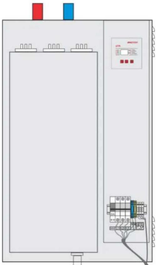
natural_image
Electrical cabinet with wiring and control panel (no visible text or symbols)Image 6: Connected cable
| 3N ~ 400/230V 50Hz | eTK 12 | eTK 18 |
| In[A] | 3 × 17,4 | 3 × 26,2 |
| Fuses [A] | 3 × 25 | 3 × 32 |
| Min. cable cross section | 5 × 4mm^2 | 5 × 4mm^2 |
| eTK 24 | eTK 30 | eTK 36 |
| 3 × 34,8 | 3 × 43,5 | 3 × 52,2 |
| 3 × 40 | 3 × 50 | 3 × 63 |
| 5 × 6mm^2 | 5 × 10mm^2 | 5 × 10mm^2 |
Table 5b: Nominal current required el. fuses and cross-section of required power cables for three-phase power supply
5.2 Connecting power (voltage) cable
- Commencing should be performed according to the mounting scheme as given in the image 7,8,9,10,11
- In the boiler, instead of classical row immobilizer are placed three pole automatic fuses to introduce the power cable. This set of automatic fuses has remote power trigger superstructure, enabling safety set having short-lasting electric power protection and ability to react on overheating (signal from safety thermostat activates power trigger) and simultaneously turn off supply of all three phases into device
- Phase conductors are connected to three-pole fusses (L1, L2, and L3)

WARNING! When connecting phase conductors it is demanding to tight well screws in automatic fusses to achieve better join between cable and clamp

DANGER! If there is no good joint between cable and clamp, then uncontrolled warning of fusses can occur and its termination at the end
- When introducing a power cable into the boiler, through any selected set of glands, carefully patch the cable to the three-pole automatic fuses to avoid damaging the cable sets inside the device

NOTE! Only qualified person may execute connecting this device

Image 7a: ETI fuses
Scheme of boiler connecting to mono-phase power supply – ONLY FOR POWER OF 6kW AND 9kW
- Neutral (zero) duct line is connected to corresponding row immobilizer (N). Row immobilizer of zero duct line is of blue colour
- Grounding duct line should be connected in the row immobilizer clearly labeled with grounding symbol. Row immobilizer of the duct line for grounding is of green-yellow colour

NOTE: Remote voltage trigger is connected by manufacturer within safety set of this device and no cable should be connected with it

NOTE: Room thermostat is connected on additional clamps (+5V and Signal) and it interrupts voltage of 5V DC that comes from boiler table microprocessor
It is recommended to use room thermostats with independent power supply like batteries
This boiler is not predicted to work without room thermostat or external control unit
- When you are finished connecting the power cord and room thermostat, the fuse set must be lifted together with the remote voltage trigger before the unit is closed (before assembling the front panel) to ensure the power supply to the boiler
5.3 Scheme of power cable connecting
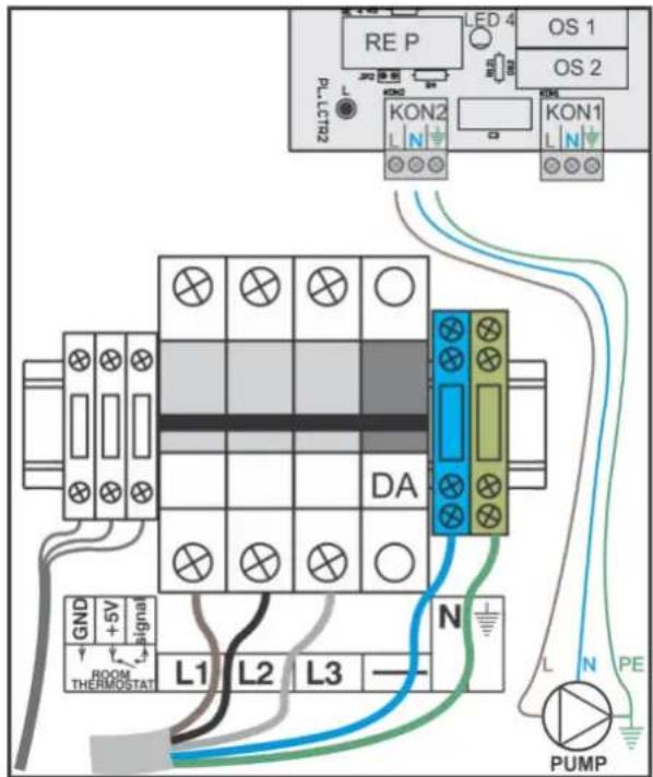
Image 7b: ETI fuses
Scheme of boiler connecting on three-phase power supply

Image 8: NOARK fuses
Scheme of boiler connecting to mono-phase power supply
- ONLY FOR POWER OF 6kW AND 9kW

Image 9: NOARK fuses
Scheme of boiler connecting on three-phase power supply
NOTE:
When there is only an electric boiler in the heating system, it is recommended to connect the external circulation as in Figures 7a, 7b, 8, 9. The pump connected in this way is controlled by a microprocessor thermostat. This means that pump management has been improved: After switching off the room thermostat, the pump remains on for another 2 minutes to remove dissipated heat energy from the heater, in case of exceeding the allowed temperature in the boiler, it also switches on and prevents overheating ... In general, control the pump is adapted to the needs of the electric boiler and in the function of protecting the boiler and the entire system. If the same pump is used by an electric boiler and a solid fuel boiler, it is recommended to connect it according to the following scheme:

flowchart
graph TD
    A["KON2"] -->|N L| B["Re P1"]
    B --> C["CP"]
    C --> D["Signal 2"]
    D -->|N L| E["Re P2"]
    E --> F["PE"]
    style A fill:#f9f,stroke:#333
    style D fill:#ccf,stroke:#333
5.4 Connect external control of boiler (room thermostat)

Image 10: Connecting scheme of digital programmable room thermostat (with battery supply)
The signal from the microprocessor thermostat via KON2 includes Relay P1. Signal 2 comes from the solid fuel boiler (or from the lean) thermostat and includes Relay P2. Contact systems transmit both relays the same phase to the Pump. If any Pump start signal is active - the pump is switched on. If there are signals to switch on the pump from both boilers - the pump is switched on safely. This kind of connection the pump ensures its operation that suits both boilers.
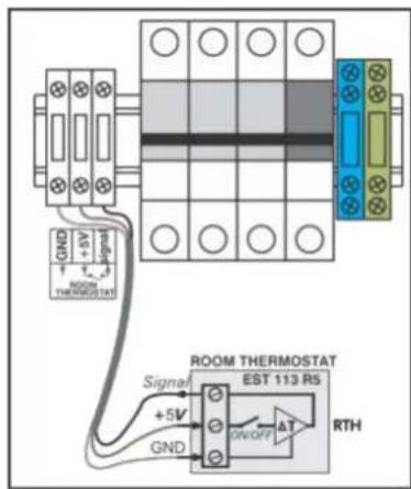
Image 11: Scheme of room thermostat MIKOTERM EST 113 R5 connecting
5.5 Electric schemes of connection

All quoted cross-sections of cables are minimal. Cross-sections that should be placed depend on length of the line and placing mode.
- Cable cross-sections should be dimensioned according to
| Legend | |
| 3P A | Three-pole automatic fuse |
| DA | Remote power trigger |
| ST | Safety thermostat (Klixon) |
| RTH | Room thermostat |
| RS 1, RS 2, RS 3 | Connecting clamps of room thermostatWARNING: voltage 5V DC |
| P1 | Main switcher ON/OFF |
| KON 2 | External pump connection connector |
| RK1, RK2, RK3 | Relay contact (for 9,12 and 18kW) |
| K1 ÷ K6 | Contactor (for 24,30 and 36kW) |
| G1 | Heater-3×1500W for boiler of: 9 kW-3×2000W for boiler of: 12,18,30 kW-3×2667W for boiler of: 24 kW-3×2400W for boiler of: 36 kW |
| G2 | Heater-3×1500W for boiler of: 9 kW-3×2000W for boiler of: 6,12,18,30kW-3×2667W for boiler of: 24 kW-3×2400W for boiler of: 36 kW |
| G3 | Heater-3×2000W for boiler of: 18,30 kW-3×2667W for boiler of: 24 kW-3×2400W for boiler of: 36 kW |
| G4 | Heater-3×2000W for boiler of: 30 kW-3×2400W for boiler of: 36 kW |
| G5 | Heater-3×2000W for boiler of: 30 kW-3×2400W for boiler of: 36 kW |
| Legend | |
| LCTR 2 | Microprocessor thermoregulator |
| OS 1 | Electric fuse 230V T500mA |
| OS 2 | Electric fuse 230V T2A |
| OS 3 | Electric fuse 24V T500mA |
| OS 4 | Electric fuse 8V T500mA |
| KON1 | Supply connector (230V AC) |
| K 102 | Temperature sensor connection |
| TS | Temperature sensor |
| K 105 | Interface connection (LCI2) |
| K 106 | Room thermostat connection (RTH) |
| RE 1 | -Relay 1/3 heater (for 6 kW boiler)-Relay switches RK1 (9, 12 and 18kW)-Relay for switching K1 (24kW)-Relay for switching on K1 and K2 (30 and 36kW) |
| RE 2 | -Relay 1/3 heater (for 6 kW boiler)-RK2 switching relays (9, 12 and 18kW)-Relay for switching K2 (24kW)-Relay for switching on K3 and K4 (30 and 36kW) |
| RE 3 | - Relay 1/3 heater (for 6 kW boiler)- Relay for switching RK3 (9, 12 and 18kW)- Relay for switching K3 (24kW)- Relay for switching K5 and K6 (30 and 36kW) |
Table 4: Legend of connecting schemes

flowchart
graph TD
    subgraph RTH
        A["ΔT"] --> B["RS 3"]
        C["RS 2"] --> D["RS 1"]
        E["Signal"] --> F["K106"]
        G["GND"] --> H["GND 5V"]
    end

    subgraph LCTR 2
        I["LCTR 2"] --> J["OS 1: 230V AC/24+8V DC"]
        K["OS 2"] --> L["OS 3: 8V"]
        M["OS 4"] --> N["OS 5: 24V"]
        O["OS 5"] --> P["OS 4: 8V"]
        Q["OS 4"] --> R["OS 3: 24V"]
        S["OS 3"] --> T["OS 4: 8V"]
        U["OS 4"] --> V["OS 5: 24V"]
        W["OS 5"] --> X["OS 4: 8V"]
        Y["OS 5"] --> Z["OS 4: 8V"]
        AA["OS 4"] --> AB["OS 5: 24V"]
        AC["OS 5"] --> AD["OS 4: 8V"]
        AE["OS 5"] --> AF["OS 4: 8V"]
        AG["OS 5"] --> AH["OS 4: 8V"]
        AI["OS 5"] --> AJ["OS 4: 8V"]
        AK["OS 5"] --> AL["OS 4: 8V"]
        AM["OS 5"] --> AN["OS 4: 8V"]
        AO["OS 5"] --> AP["OS 4: 8V"]
        AQ["OS 5"] --> AR["OS 4: 8V"]
        AS["OS 5"] --> AT["OS 4: 8V"]
    end

    subgraph LCTR 2
        AU["KON 2"] --> AV["K105"]
        AW["KON 2"] --> AX["K102"]
        AY["KON 2"] --> AZ["K105"]
        BA["KON 2"] --> BB["K102"]
        BC["KON 2"] --> BD["K105"]
    end

    subgraph eTK
        BE["MIKOTERM eTK"]
        BF["HIKOTERM eTK"]
    end

    subgraph LCI 2
        BG["LCI 2"]
    end

    P1 --> KON1
    KON1 --> OS1
    OS1 --> OS2
    OS2 --> RE4
    RE4 --> PE
    PE --> KON2
    KON2 --> K105
    K105 --> TS
    ST --> DA
    DA --> L1
    DA --> L2
    DA --> L3
    L1 --> L1a
    L1 --> L1b
    L1 --> L2a
    L1 --> L3a
    L2a --> L2b
    L2b --> L3a
    L3a --> L3b
    L3b --> PE
    PE --> G1
    G1 --> G1a
    G1a --> G1b
    G1b --> G1c
    G1c --> TS
    BT["HIKOTERM eTK"] --> BI["HIKOTERM eTK"]
    BI --> BIa["HIKOTERM eTK"]
    BI --> BIb["HIKOTERM eTK"]
    BI --> BIc["HIKOTERM eTK"]
    BI --> BId["HIKOTERM eTK"]
    BI --> BIe["HIKOTERM eTK"]
    BI --> BIf["HIKOTERM eTK"]
    BI --> BIg["HIKOTERM eTK"]
    BI --> BIh["HIKOTERM eTK"]
    BI --> BIi["HIKOTERM eTK"]
    BI --> BIj["HIKOTERM eTK"]
    BI --> BIk["HIKOTERM eTK"]
Image 12a: Boiler electric scheme eTK with nominal power of 6kW

flowchart
graph TD
    subgraph RTH
        A["ΔT"] --> B["RS 3"]
        C["RS 2"] --> D["RS 1"]
        E["ST"] --> F["95°C"]
        F --> G["DA"]
        H["L1"] --> I["L1"]
        J["L2"] --> K["L2"]
        L["L3"] --> M["L3"]
        N["N"] --> O["3PA"]
        P["PE"] --> Q["G1"]
    end

    subgraph LCTR 2
        R["OS 1"] --> S["OS 2"]
        T["OS 3"] --> U["OS 4"]
        V["OS 5"] --> W["OS 6"]
        X["RE 1"] --> Y["RE 2"]
        Z["RE 3"] --> AA["RE 4"]
        AB["KON 1"] --> AC["+5V Signal"]
        AD["KON 2"] --> AE["230V AC/24+8V DC"]
        AF["KON 5"] --> AG["8V"]
        AH["KON 105"] --> AI["TS"]
    end

    subgraph eTK
        AJ["RTH"] --> AK["Signal"]
        AL["ST"] --> AM["L1"]
        AN["L2"] --> AO["L2"]
        AP["L3"] --> AQ["L3"]
        AR["N"] --> AS["3PA"]
    end

    subgraph LCI 2
        AS --> AT["L1"]
        AU["L2"] --> AV["L2"]
        AW["L3"] --> AX["L3"]
        AY["P1"] --> AZ["GND"]
        BA["P1"] --> BB["GND 5V"]
    end

    subgraph MIKOTERM
        BC["eTK"] --> BD["Temp. Set temp. Power Set power"]
    end
Image 12b: Boiler electric scheme eTK with nominal power of 9kW and 12kW
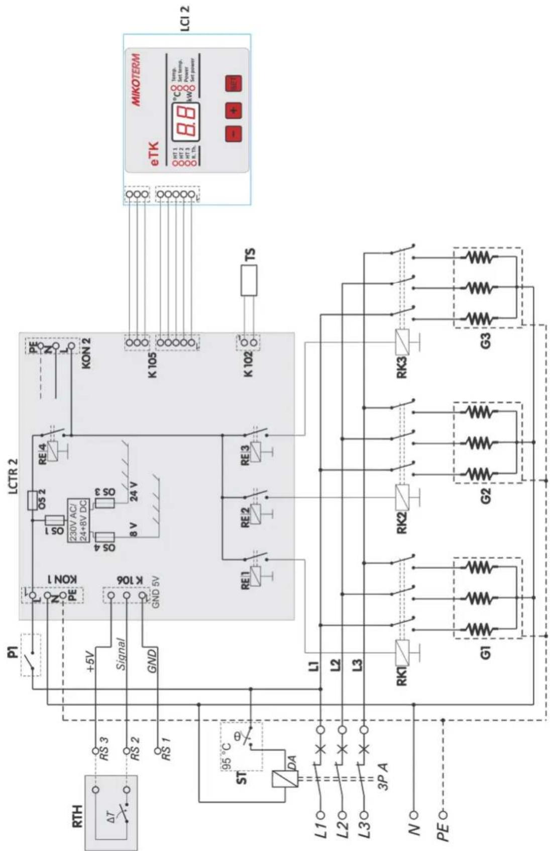
flowchart
graph TD
    subgraph RTH
        A["ΔT"] --> B["RS 3"]
        C["RS 2"] --> D["RS 1"]
        E["ST"] --> F["95°C"]
        F --> G["DA"]
        H["L1"] --> I["×"]
        J["L2"] --> K["×"]
        L["L3"] --> M["×"]
        N["N"] --> O["○"]
        P["PE"] --> Q["○"]
    end

    subgraph LCTR 2
        R["KON 1"] --> S["+5V Signal"]
        T["KON 2"] --> U["8 V 24V"]
        V["KON 3"] --> W["230V AC/24+8V DC"]
        X["KON 4"] --> Y["RE 1"]
        Z["KON 5"] --> AA["RE 2"]
        AB["KON 6"] --> AC["RE 3"]
    end

    subgraph eTK
        AD["HIKOTERM"] --> AE["8.8°C Temp. Set temp. Power Set power"]
    end

    F --> F
    F --> F
    F --> F
    F --> F
    F --> F
    F --> F
    F --> F
    F --> F
    F --> F
    F --> F
    F --> F
    F --> F
    F --> F
    F --> F
    F --> F
    F --> F
    F --> F
    F --> F
    F --> F
    F --> F
    F --> F

    subgraph LCI 2
        G1["G1"] --> G2["G2"]
        G3["G3"]
    end

    subgraph LCTR 2
        H1["OS 1"] --> H2["OS 2"] --> H3["OS 3"] --> H4["OS 4"] --> H5["OS 5"]
        H6["RE 4"] --> H7["RE 5"]
        H8["RE 6"] --> H9["RE 7"]
        H10["RE 8"] --> H11["RE 9"]
        H12["RE 10"] --> H13["RE 11"]
        H14["RE 12"] --> H15["RE 13"]
        H16["RE 14"] --> H17["RE 15"]
        H18["RE 16"] --> H19["RE 17"]
        H20["RE 18"] --> H21["RE 19"]
        H22["RE 20"] --> H23["RE 21"]
        H24["RE 22"] --> H25["RE 23"]
        H26["RE 24"] --> H27["RE 28"]
        H28["RE 29"] --> H30["RE 30"]
        H31["RE 31"] --> H33["RE 32"]
        H32["RE 33"] --> H35["RE 36"]
        H33 --> H37["RE 38"]
        H34 --> H39["RE 40"]
        H35 --> H41["RE 42"]
        H36 --> H43["RE 44"]
        H37 --> H45["RE 46"]
        H38 --> H47["RE 48"]
        H39 --> H50["TS"]
    end

    subgraph LCI 2
        AI["LTR"] --> AJ["LTR 1"]
        AK["LTR 2"] --> AL["LTR 3"]
        AM["LTR 4"] --> AN["LTR 5"]
        AO["LTR 6"] --> AP["LTR 7"]
        AQ["LTR 8"] --> AR["LTR 9"]
        AS["LTR 10"] --> AT["LTR 11"]
        AU["LTR 12"] --> AV["LTR 13"]
        AW["LTR 14"] --> AX["LTR 15"]
        AY["LTR 16"] --> AZ["LTR 17"]
        BA["LTR 18"] --> BB["LTR 19"]
        BC["LTR 20"] --> BD["LTR 21"]
        BE["LTR 21"] --> BF["LTR 22"]
        BG["LTR 23"] --> BH["LTR 24"]
        BI["LTR 25"] --> BJ["LTR 26"]
        BK["LTR 27"] --> BL["LTR 28"]
        BM["LTR 29"] --> BN["LTR 30"]
        BO["LTR 31"] --> BP["LTR 32"]
        BQ["LTR 33"] --> BR["LTR 34"]
        BS["LTR 35"] --> BT["LTR 36"]
        BU["LTR 37"] --> BV["LTR 38"]
        BW["LTR 39"] --> BX["LTR 40"]
        BY["LTR 41"] --> BZ["LTR 42"]
        CA["LTR 43"] --> CB["LTR 44"]
        CC["LTR 45"] --> CD["LTR 46"]
        DEL["LTR 47"] --> DF["LTR 48"]
        DGL["LTR 49"] --> DH["LTR 50"]
        DI["GND"] --> DJ["GND 5V"]
    end

    subgraph LCTR_2
        E1["KON 1"] --> E2["KON 2"]
    end

    subgraph LCI_2
        AE[MIKOTERM eTK HT-1 HT-2 HT-3 HT-Th. Temp. Set temp. Power Set power - + + + -
      end
Image 13a: Boiler electric scheme eTK with nominal power of 18kW

flowchart
graph TD
    subgraph RTH
        A["ΔT"] --> B["RS 3"]
        C["RS 2"] --> D["RS 1"]
        E["Signal"] --> F["K106"]
        G["GND"] --> H["GND 5V"]
    end

    subgraph LCTR 2
        I["LCTR 2"] --> J["OS 1, OS 2, OS 3, 230V AC/24+8V DC, 8V, 24V"]
        K["PE"] --> L
        L --> L
        L --> M["KON 2"]
        N["K105"] --> O["TS"]
        P["K102"] --> Q["TS"]
    end

    RST --> S["95 °C"]
    S --> T["DA"]
    T --> U["ST"]
    U --> V["L1"]
    V --> W["L2"]
    W --> X["L3"]
    X --> Y["3P A"]
    Y --> Z["N"]
    Z --> AA["PE"]

    subgraph eTK
        AB["MIKOTERM"] --> AC["8.8°C Temp. Set temp. Power Set power"]
    end

    subgraph LCI 2
        AD["RLI 2"] --> AE["TS"]
    end
Image 13b: Boiler electric scheme eTK with nominal power of 24kW

flowchart
graph TD
    subgraph RTH
        A["ΔT"] --> B["RS 3"]
        C["RS 2"] --> D["RS 1"]
        E["ST"] --> F["95 °C"]
        F --> G["DA"]
    end

    subgraph LCTR 2
        H["LCTR 2"] --> I["OS 1: 230V AC/24+8V DC"]
        J["KON 2"] --> K["OS 4: 8V, OS 3: 24V"]
        L["KON 5"] --> M["OS 4: 8V, OS 3: 24V"]
        N["KON 2"] --> O["OS 4: 8V, OS 3: 24V"]
        P["KON 2"] --> Q["OS 4: 8V, OS 3: 24V"]
        R["KON 2"] --> S["OS 4: 8V, OS 3: 24V"]
        T["KON 2"] --> U["OS 4: 8V, OS 3: 24V"]
    end

    V["Signal"] --> W["GND"]
    X["PE"] --> Y["GND"]
    Z["L1"] --> AA["L2"]
    AB["L2"] --> AC["L3"]
    AD["L3"] --> AE["3P A"]
    AF["N"] --> AG["PE"]
    AH["G1"] --> AI["G2"] --> AJ["G3"] --> AK["G4"] --> AL["G5"]

    AM["K1"] --> AN["K2"]
    AO["K3"] --> AP["K4"]
    AQ["K5"] --> AR["K6"]

    AS["TS"] --> AT["MIKOTERM eTK"]
    AU["Temp. Set temp. Power Set power"] --> AV["8.8°C kW"]
    AW["+"] --> AX["+"]
    AY["RE1"] --> AZ["RE2"] --> BA["RE3"]
    BB["RE4"] --> BC["RE5"]
    AD --> BD["TS"]
    AE --> BE["TS"]
    AF --> BF["TS"]
    AG --> BG["TS"]
    AH --> BH["TS"]
    AI --> BI["TS"]
    AJ --> BJ["TS"]
    AK --> BK["TS"]
    AL --> BL["TS"]
    AM --> BM["TS"]
    AN --> BN["TS"]
    AO --> BO["TS"]
    AP --> BP["TS"]
    AQ --> BQ["TS"]
    AR --> BR["TS"]
    AS --> BS["TS"]
    BT["L1"] --> BU["L2"]
    BV["L2"] --> BW["L3"]
    BX["L3"] --> BY["3P A"]
    BY --> BZ["L1"]
    BA --> CA["L2"]
    BB --> CB["L3"]
    CC["K1"] --> CD["K2"] --> CE["K3"] --> CF["K4"] --> CG["K5"] --> DH["K6"]

    style RTH fill:#f9f,stroke:#333
    style LCTR 2 fill:#ccf,stroke:#333
    style MIKOTERM eTK fill:#cfc,stroke:#333
    style LCI 2 fill:#fcc,stroke:#333
Image 14: Boiler electric scheme eTK with nominal power of 30kW and 36kW
6. Commissioning
When complete below described works fill in the Commissioning log (chapter 6.3).
6.1 Before commissioning

NOTE: Material damage occurred due to unprofessional operating! Start-up without sufficient quantity of water destroys device
▶ Turn on the boiler and use it only if there is sufficient quantity of water

Boiler must work with minimum pressure of 0.5 bars
Before turn on, test if the following elements and joints are connector correctly and work correctly:
• Watertight of heating installation
• All pipes connected into ducts
• All electric connectors
6.2 First turn on

NOTE: Material damage due to incorrect handling!
▶ Instruct client/user how to handle device
- Prior to turn on check if heating installation is filled with water and air-vent
- Turn on main switcher (below device)
- Heating system and device parameters will appear on display
- Device is adjusted by default on min temperature of 10^ C and power of 0 kW
- Only the pressure value in installation on display will be the one which you adjusted during filling the installation with water
6.3 Start-up log
| 1. | Boiler type | |
| 2. | Serial number | |
| 3. | Set thermostat regulation | ☐ |
| 4. | Fill and air-vent heating installation and check sealing of all connectors | ☐ |
| 5. | Establish working pressureCheck expansion dish pressure | barbar |
| 6. | Test safety devices | ☐ |
| 7. | Set electric connection according to local regulations | ☐ |
| 8. | Test function | ☐ |
| 9. | Users informed, technical documentation submitted | ☐ |
| 10. | Notes | |
| 11. | Certificate of professional turn on device | Service seal / Signature / Date |
Table 5: Start-up log
7. Heating installation handling
7.1 Working Instruction
Safety Instructions
- Only adults familiar with instructions and working mode may operate the boiler
- Make sure there are no children in the boiler area
- Do not dispose or store inflammable materials within safe distance of 400 mm round the boiler
- Inflammable materials must not be placed on the boiler
- User must comply with instructions for operating the boiler
- User may only turn on the boiler (except the first start-up), adjust temperature on the regulating device and turn off the boiler. All other operations must be performed by authorised service
- Authorised person who performed installation is obliged to inform the user about handling and correct and safe work of boiler
- In the event of alert situation, explosion, fire, gas or steam leaking, the boiler must not work
- Be aware of inflammable characteristics of components (Instructions on installations and maintenance)
7.2 Overview of the elements to adjust
7.2.1 Device functions
- eTK is a classic type of electric boiler, without a circulation pump and expansion vessel. The construction of eTK is robust, and the built-in components are of top quality. It is enriched with a microprocessor thermoregulator, which is the most important difference compared to the previous model (TK)
- The safety of the device is at the maximum level, because a protective circuit is installed - the same as with the "mTronic" and "eCompact Plus" models
- Communication of the user, as well as the installer (servicer) with the device is done through the user interface where you can easily see and adjust all the important parameters of the device
- Genuine software allows for longer service life. The microcontroller continuously monitors the information received from the sensor, measures the operating time of the heater, and based on that evenly loads all vital components
- Also, the microcontroller monitors the dynamic growth of temperature and based on that and the set power optimizes the engaged power of the boiler - which means minimal electricity consumption. Energy
7.2.2 Basic adjustments
The current temperature is continuously displayed on the display, indicating the LED that is lit beside the "Temp" mark. To display other parameters, use the keys “-” and “+”. In addition to the selected parameter whose value is displayed on the display, the LED indicator lights up.
The "SET" key is used to enter the set parameter value (next to the LED). The same key is also used to store the new set parameter value and exit the setting.
The parameters that can be set are:
- " Set temp " - set the temperature
- " Set power " - power setting
The temperature can be set in the range of 10 °C to 80 °C , in steps of 1 °C .
The default power can be set in three steps depending on the nominal power of the unit (see table). Turn on / off the heater is carried out periodically with a delay of 3 sec, which avoids the strike on the power grid.
| Boiler power | Steps (kW) |
| 6 kW | 2+2+2 |
| 9 kW | 3+3+3 |
| 12 kW | 4+4+4 |
| 18 kW | 6+6+6 |
| 24 kW | 8+8+8 |
| 30 kW | 6+6+6+6+6 |
| 36 kW | 7,2+7,2+7,2+7,2+7,2 |
Table 6: Power and adjusting steps
- For normal work of this device it is necessary to set working pressure in range between 0.5÷2.0 bar (recommendation is 1.0bar) during filling and maintenance
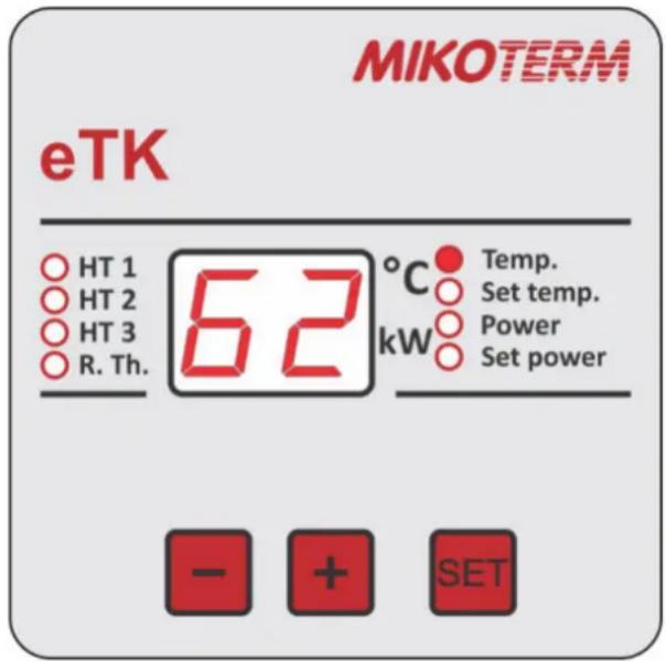
Image 15: Control panel view

WARNING!: If working pressure continues to grow up to 3 bar mechanical safety valve will start to leak heating water out of the boiler.
- HT 1: Indicates work of heater no. 1
- HT 2: Indicates work of heater no. 2
- HT 3: Indicates work of heater no. 3
- R.Th.: Indicates room thermostat
- Temp: Present temperature display [°C]
- Set temp: Set temperature display [°C]
- Power: Present engaged power [kW]
- Set power: Set engaged power [kW]
- “-” Button to reduce parameters value and search down through Menu
- “+” Button to increase parameters value and search up through Menu
- "SET": Button to select parameter
7.3 Regulation of heating
- Circulating pump and electrical heaters turn on by command of room thermostat
- When boiler reaches set temperature of water in the system, heaters turn off (with intervals of 3 sec to eliminate shock to electric power net). When the current water temperature drops 2 °C below the set - the heaters are switched on again, but not all, but 1/3 of the set power. The controller monitors the dynamic temperature rise and based on that determines the minimum engaged power of the heater, which is sufficient to maintain the set temperature of the boiler, ie minimizes electricity consumption. Energy Microprocessor thermo-regulator measures time of work for each heater, changes heaters (if there is inactive heater available) after 30 min of continual work. Such working mode provides equal load of all heaters and relays, and their life-time is significantly longer
- When room temperature is reached, microprocessor turns off heaters.
7.3.1 Boiler set temperature adjusting
Using buttons “-” or “+” select mod to display set temperature - LED diode near the sign „Set temp“ is on. Press button "SET", LED diode near to the sign „Set Temp“ starts to flash, which means it is possible to increase/decrease given temperature of the boiler using button “-” or “+” (image 16). Each touch to the button will increase/decrease given temperature of the boiler for 1 °C. Working temperature range is 10 °C ÷ 80 °C.
Confirmation of change must be done by pressing button "SET". If change is not confirmed, 15 sec after pressing any button (except "SET"), controller continues to work on old value of set temperature and exits adjusting mode.
When change is confirmed pressing button "SET", display keeps the new value of temperature for 15 sec, and then returns back to basic representation, or the present temperature will appear on display.

Image 16: Given boiler temperature adjusting
7.3.2 Boiler given power adjusting
Use the “-” or “+” buttons to select the mode for setting the default power - the LED next to the "Sets power" indicator lights up. Now press the "SET" button - the LED blinks next to "Set Power", which means that it is possible to increase or decrease the default power boiler using the “-” or “+” buttons. Each keystroke increases or decreases the default power boiler 1 step power (see Table 6).
In order for the change to be accepted it must be confirmed by pressing the "SET" key. If the change is not confirmed, within 15 sec. by pressing any key (except for "SET"), the control resumes operation according to the old default power value and exits from the setting mode.
When the default power change is confirmed by pressing the "SET" key, the display will display a new setpoint of 15 sec and then return to the basic display, the display will show the current temperature.
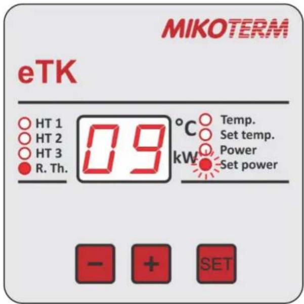
Image 17: Given boiler power adjustment
7.3.3 Low temperature warning
If temperature of the system decreases to T≤4 °C, the boiler continues to work normally, but measuring temperature indicator starts to flash slowly (image 21). It is necessary to increase temperature to T≥5 °C in order to stop automatic flashing of warning indicator.

Image 21: Warning- Temperature near restricted low temperature

WARNING! If heating system is out of function the freezing can occur
It is mandatory to secure the system
▶ Empty the entire installation
If temperature of the system decreases to T≤2 °C, all heaters and pump will turn off (delays for 2 min), and temperature measuring indicator will flash quickly (image 22). With this temperature value there is danger of freezing and boiler damage, so the work of this device will be blocked. To continue with boiler work it is necessary to increase temperature up to T≥5°C.

Image 22: Blocked work of the boiler foe to danger of freezing
Present temperature displayed on the screen is possible for values T≥-9°C. Temperature below -9°C is not possible to be displayed on the screen so the code EL will appear on display meaning the temperature is below -9°C, or temperature sensor is in circuit break (image 23).

Image 23: Temperature below -9 °C or sensor circuit break

WARNING: Material damage due to freezing
7.3.4 Warning with high temperature
If temperature of the system increases to T≥85°C, the pump works continually (due to taking heating energy through pipe routing network), but measuring temperature indicator starts to flash slowly (image 24). It is necessary to decrease temperature to T≤84°C in order to stop automatic flashing of warning indicator and continue with normal work of boiler.

Image 24: Warning – Temperature close to restricted high temperature value
If temperature of the system increases to T≥89°C, the pump works continually (due to taking heating energy through pipe routing network), but measuring temperature indicator starts to flash quickly (image 25). It is necessary to decrease temperature to T≤88°C in order to stop automatic flashing of this mistake warning indicator.

Image 25: Blocked work of the heaters due to danger of thermic overload, pump work continually
If temperature increases to T≥100 °C, display of its value is not possible to see on the screen so in this will appear code EH meaning that temperature is T≥100 °C (image 26). Measuring temperature indicator will continue to flash quickly.
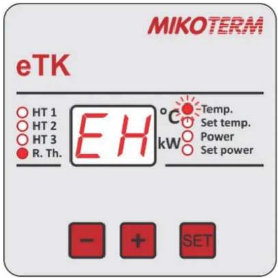
Image 26: Temperature above 99 °C

WARNING: Material damage due to overheating
In this case it is necessary to turn off this device out of electric power supply and call authorised service to establish and remove the cause of problem.
If temperature sensor is damaged (or disconnected), the code ES will appear on the screen meaning "Error temperature Sensor" (image 27). Temperature measuring indicator will continue to flash quickly.
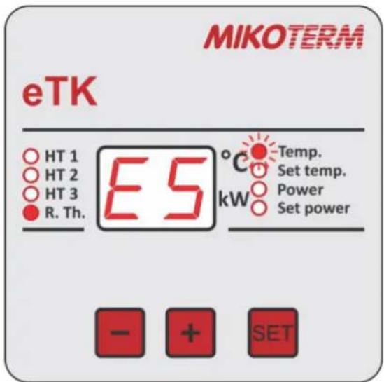
Image 27: Temperature sensor in discontinuity
In this case it is necessary to turn off this device out of electric power supply and call authorised service to establish and remove the cause of problem.
7.3.5 Signal and code of warning and mistakes
Temp. - slow flashing - Warning: lower limit exceeding (T≤4 °C) or upper limit (T≥85 °C) of temperature of the heating system Measure: Check if valves are open, the functionality of circulation pump and relay/contactor
Temp. - quick flashing - Mistake: lower limit exceeding (T≤2 °C) or upper limit (T≥89 °C) of temperature of the heating system Measure: Turn off electric power supply for the boiler. Call service
Graphic display of the area of blockade of the boiler work conditioned by temperature (1.temp. increases→ / 2.temp. decreases←)
![WORK BLOCKADE EL -9 3 4 5 WARNING NORMAL WORK NORMAL WORK 78 80 84 85 89 90 99 WARNING WORK BLOCKADE [°C]](/content/2026/05/979697/images/2d8bb7b1d421fe20086c6d334985de494be10ae49ec51abfef5c8e79fa13bd13.jpg)
Mistake signals on display
EL - Mistake: Very low boiler temperature (T ≤ -9 °C) or short-circuit temperature sensor - all turned off Measure: Turn off power supply. Call service.
EH - Mistake: Very high temperature (T≥100 °C) not able to display – all turned off Measure: Turn off power supply. Call service.
ES - Mistake: Boiler temperature sensor breaker – all turned of Measure: Turn off power supply. Call service.
7.3.6 Room temperature regulator
This device is not designed for work without room temperature regulator. Room thermostat must be installed in reference room.
Managing temperature of all rooms is done by this remote control. Radiators in reference room should not be equipped by thermo-static valves or these must always be open. All radiators in other rooms must be equipped by thermostat valves. Connecting room-regulator is described in chapter 5.4. When mounting room-regulator in reference room you must comply with manufacturer instructions.
7.3.7 Heating discontinuity
With short-time discontinuity of heating working regime the boiler temperature must be decreased using thermo-regulator of the boiler. To prevent heating installations freezing temperature of the boiler must not be set below 5^ C. With longer discontinuity of heating working regime of the boiler must be cut off the power (chapter 7.4).
7.4 Boiler out of power
If heating installation is not in drive, it could freeze with low temperatures.
- Protect heating installations against freezing
- If there is danger of freezing and boiler is not in drive, discharge entire installation
- Main power breaker on lower plate put in position „0“ (put off)
8. Cleaning and maintenance

DANGER! Life threat of electric power shock!
▶ Electric power work must be done only by qualified person
▶ Before opening device: turn heating installation off electric power supply using safety switcher and disconnect it from power supply net through corresponding fuse
▶ Secure heating installation against accidental turn on
▶ Comply with instructions for installation

WARNING: Material damage due to unprofessional maintenance!
Insufficient or unprofessional maintenance of boiler can lead to damage or destruction and to loss of Warranty rights
▶ Secure regular, entire and professional maintenance of heating installation
▶ Electric parts and work units protect against water and humidity

Use only spare parts delivered by the manufacturer or those approved by manufacturer. There will be no responsibility for damage occurred due to spare parts not delivered by the manufacturer

Control examination log is provided on chapter 8.4
- Perform works in accordance with log on control and maintenance
- All deficiencies remove immediately
8.1 Boiler cleaning
Clean this device externally with wet cloth
8.2 Check working pressure; re-fill water and air-vent installation

DANGER: Health threat due to mix of drinking water!
It is demanding to respect state regulations to avoid mix of drinking water (with water from heating installations)
▶ Comply with EN 1717

Establish a working pressure of at least 1 bar, depending on the height of the highest point of the installation. If, due to the height of the installation, the operating pressure is greater than 1 bar (eg 1.5 bar) before the system is filled with water, it is necessary to lift the air intake in the expansion vessel to the same value - 1.5 bar
The volume of newly filled water is reduced in the first days after charging due to heating. This creates airbags that create interference in the heating system.
Testing working pressure
- Working pressure of new heating installation should control on daily basis at the beginning of its work. If needed, re-fill water and air vent the system
- Later check working pressure once per month. If needed, re-fill water and air vent the system
- Check working pressure. If it decreases below 0,5 bar refill water
- Re-fill the water
• Air vent the heating installation - Check working pressure again
8.3 Re-fill the water and air-vent the installation

WARNING: Material damage due to heat tension. Filling heating installations in warm condition can produce cracks due to tension
▶ Fill heating installation only in cold condition (temperature of starting duct lines of max 40 °C)

WARNING: Material damage due to frequent re-filling!
Due to frequent water re-filling installations can be damaged by corrosion and carbonate layers depending on water characteristics
▶ Test sealing and watertight of heating installations and expansion dish on functionality
- Connect hose on water faucet
- Fill the hose with water and connect to connector for filling/draining
- Tighten the hose and open the water faucet for filling/draining
- Slowly fill the heating installation while following up with pressure (manometer)
• During filling procedure air vents the system - When reach working pressure close the drainage faucet
- When reach working pressure close the drainage faucet
- Remove the hose from filling/drainage faucet
8.4 Inspection and maintenance
The commissioning, inspection and maintenance record serves as an attachment for copying
- Executed works should be authorised by signature and date

At least once a year perform maintenance or when a check shows the status of installations that require maintenance
| Inspection and maintenance works when needed | Date: ____ | Date: ____ | Date: ____ | |
| 1. | Check condition of installations | ☐ | ☐ | ☐ |
| 2. | Visual and functional control | ☐ | ☐ | ☐ |
| 3. | Making working pressureCheck pre-pressure of expansion dishWorking pressure set on ...Heating installation air ventCheck safety heating valve | ☐_bar☐☐ | ☐_bar☐☐ | ☐_bar☐☐☐ |
| 4. | Clean water filter | ☐ | ☐ | ☐ |
| 5. | Check if there is any damage on electric duct lines | ☐ | ☐ | ☐ |
| 6. | Check if electric control connections and used elements are fitted; tighten it if needed | ☐ | ☐ | ☐ |
| 7. | Check thermo-regulator on boiler | ☐ | ☐ | ☐ |
| 8. | Check function of safety parts | ☐ | ☐ | ☐ |
| 9. | Check remote control function | ☐ | ☐ | ☐ |
| 10. | Check insulation of the rod heater | ☐ | ☐ | ☐ |
| 11. | Check function of grounding device | ☐ | ☐ | ☐ |
| 12. | Check insolation of electric switchboard | ☐ | ☐ | ☐ |
| 13. | Check heating pump function | ☐ | ☐ | ☐ |
| 14. | Make final control of inspection works and document results of measuring and inspecting | ☐ | ☐ | ☐ |
| 15. | Certification of professionally conducted inspection | Seal/Signature | Seal/Signature | Seal/Signature |
Table 7: Inspection and maintenance log
9. Environment protection /Waste disposal
One of the basic concepts of business is environment protection. Quality of products, thriftiness and environment protection are equally valuable goals for us. It is critical to strictly comply with law and regulations on environment protection. In order to protect environment and respecting economy concepts we use only the best technique and materials.
Packaging
Regarding packaging, we respect system of recycling which is specific in certain states and which secure optimal recycling All materials applied for packaging do not harm environment and It is possible to recycle it.
Old devices
Old devices contain valuable materials that can recycle. Structures are easily demountable and plastic materials are labeled. In such manner structures can be sorted and deliver for recycling.
10. Troubles and troubleshooting

Troubleshooting on regulations and hydraulics must be done by an authorised firm

For repairs use only original spare parts
| TROUBLE | DESCRIPTION | CAUSE | MEASURE |
| Boiler does not react after turn on of main switcher | Display does not react, other components do not work | · Boiler is out of power supply· Fuses on bottom plate are off· Vanishing of managing phase· Damage of main fuse ON/ OFF | · Provide power supply· Turn on fuses· Check if fuses have three phases on output· Change damaged part |
| Boiler does not heat or insufficiently heat/heating pump works | All on display are within recommended values but boiler does not make hot water | · Lack of 1 or 2 phases· Small power of boiler· Some relay damaged· Some heater damaged | · Check all three phases· Check set power of boiler· Change damaged part· Change damaged part |
| Boiler heats but it is very noisy | Higher level of noise during work | · Air in the system· Small water flow· Possible carbonate layer on heater | · Check if the system is air vented and vent it· Check valves below boiler and open it· Clean filter below boiler· Take out heaters and clean it (this is not included in claims during warranty period) |
| Boiler turns on quickly | Reaches temperature too quickly and turns on | · Valves below the boiler off· Pump fuse stop to work· Pump jammed· Pump inaccurate | · Open valves· Change inaccurate part· Start pump rotor· Change inaccurate part |
| Great oscillations of working pressure | Too fast and too big changes of working pressure | · One valve off· Expansion dish pressure inadequate· Inaccurate dish | · Open the valve· Check pressure in expansion dish and if needed set dish pressure adequately· Change inaccurate part |
Table 8: Troubles and troubleshooting
12. Product data sheet (in accordance with EU regulation no. 811/2013)
| 1. | Manufacturer | MIKOTERM DOO | |
| 2. | Brand name | eTK | |
| 3. | Models | I | eTK 6kW |
| II | eTK 9kW | ||
| III | eTK 12kW | ||
| IV | eTK 18kW | ||
| V | eTK 24kW | ||
| VI | eTK 30kW | ||
| VII | eTK 36kW |
| I | II | III | IV | V | VI | VII | ||||
| 4. | Room heating: Seasonal energy-efficiency class | D | D | D | D | D | D | D | ||
| 5. | Room heating: Nominal heat output(*8) (*11) | P_rated | kW | 6 | 9 | 12 | 18 | 24 | 30 | 36 |
| 6. | Room heating: Seasonal energy efficiency(*8) | ηs | % | 37,39 | 37,55 | 37,66 | 37,76 | 37,82 | 37,87 | 37,93 |
| 7. | Annual energy consumption(*8) | QHE | kWh | 6600 | 11022 | 13266 | 22088 | 28756 | 35655 | 42786 |
| 8. | Sound power level, indoor | LWA indoor | dB(A) | 32 | 35 | 35 | 41 | 41 | 46 | 46 |
| 9. |  All specific precautions for assembly, installation and maintenance are described in the operating and installation instructions. Read and follow the operating and installation instructions. All specific precautions for assembly, installation and maintenance are described in the operating and installation instructions. Read and follow the operating and installation instructions. | |||||||||
| 10. |  All of the data that is included in the product information was determined by applying the specifications of the relevant European directives.Differences to product information listed elsewhere may result in different test conditions. Only the data that is contained in this product information is applicable and valid. All of the data that is included in the product information was determined by applying the specifications of the relevant European directives.Differences to product information listed elsewhere may result in different test conditions. Only the data that is contained in this product information is applicable and valid. | |||||||||
(*8) For average climatic conditions
(*11) For boilers and combination boilers with a heat pump, the nominal heat output "Prated" is the same as the design load in heating mode "Pdesignh", and the nominal heat output for an auxiliary boiler "Psup" is the same as the additional heating output "sup(Tj)"
MIKOTERM DOO
Serbia, Bul.Sv. cara Konstantina 82 18000 Niš
00 381 18 4542002 / 3409702 / 3409703
www.mikoterm.com
office@mikoterm.com
This document is the property of MIKOTERM d.o.o. and any duplica on and copying thereof is punishable by law. The contents of technical documenta on and technical solu ons from this manual are protected by intellectual property of MIKOTERM d.o.o. Any unauthorized use, copying or publication, in whole or in part, by other en es without the authoriza on of MIKOTERM d.o.o. is punishable by law.
Nis, 2022
Mikoterm d.o.o. does not assume responsibility for possible errors in this booklet produced by prin ng or duplica on, all images and schemes are in principle, it is necessary to adapt each to the actual situa on on the ground. In any case, Mikoterm reserves the right to make changes that it deems necessary on its products.
- Content
- Description of symbols and instructions for safe work
- Device data
- Transportation
- Device installing
- Electrical connection
- Commissioning
- Handling heating installation
- Cleaning and maintenance
- Environment protection / Waste disposal
- Troubles and troubleshooting
- Product data sheet (in accordance with EU regulation no. 811/2013)
- Description of symbols
- Warnings
- Important information
- Instructions for safe work
- General safety instructions
- Danger because of disrespecting security rules in alert situations, for example fire.
- Damage occurred because of wrong handling
- Installation and commissioning
- Life threat of electric power shock
- Control examination / Maintenance
- Authentic spare parts
- Material damages due to freezing
- Instructions for service
- Waste disposal
- Cleaning
- Typology
- Statement on compliances
- Regular application
- Instructions for mounting
- Instructions for work
- Inhibitors and anti-frost products
- Norms, regulations and standards
- Tools, materials and auxiliary measures
- Minimum distances and burnable construction materials
- Product description
- Waste disposal
- Delivery scope
- Factory plate
- Dimensions and technical data
- NOTE: Transport damages
- Installation of device
- Be careful prior to assembly
- Distances
- Demounting front boiler casing
- Mounting boiler
- Hydraulic attachments execution
- Systems on which the eTK boiler can be connected
- Filling the installations and watertight testing
- Filling the boiler with heating water and sealing test
- During the first filling of repeated filling or when change the water
- Heating pump air emission and de-blocking
- Boiler and installation air emission
- Electric connecting
- Positions of introducer for the introduction of the power cable
- Connecting power (voltage) cable
- NOTE:
- Electric schemes of connection
- Before commissioning
- First turn on
- Start-up log
- Heating installation handling
- Working Instruction
- Safety Instructions
- Overview of the elements to adjust
- Device functions
- Basic adjustments
- Regulation of heating
- Boiler set temperature adjusting
- Boiler given power adjusting
- Low temperature warning
- Warning with high temperature
- Signal and code of warning and mistakes
- Mistake signals on display
- Room temperature regulator
- Heating discontinuity
- Boiler out of power
- DANGER! Life threat of electric power shock!
- WARNING: Material damage due to unprofessional maintenance!
- Boiler cleaning
- Check working pressure; re-fill water and air-vent installation
- DANGER: Health threat due to mix of drinking water!
- Testing working pressure
- Re-fill the water and air-vent the installation
- Inspection and maintenance
- Environment protection /Waste disposal
- Packaging
- Old devices
- Product data sheet (in accordance with EU regulation no. 811/2013)
Brand : Mikoterm
Model : eTK 6÷36kW
Category : Central heating boiler