HT 400 - Thermostat Mikoterm - Free user manual and instructions
Find the device manual for free HT 400 Mikoterm in PDF.


| Product Type | Smart Digital Room Thermostat (Wi-Fi) |
| Brand | Mikoterm (mControl) |
| Model | HT 400 |
| Thermostat Power Supply | 5V DC, 250 mA (via USB adapter) |
| Thermostat Dimensions | 90 mm x 45 mm |
| Temperature Measurement Accuracy | 0.1°C |
| Temperature Setting Accuracy | 0.1°C – 1.0°C |
| Working Accuracy | 0.5°C |
| Operating Temperature Range | -10°C to +50°C |
| Storage Temperature Range | -20°C to +60°C |
| Modem Power Supply | 220V AC |
| Modem Dimensions | 85 mm x 90 mm x 28.5 mm |
| Relay Switching Current (NO) | 10 A (220V AC) |
| Wireless Communication | Wi-Fi 802.11 b/g/n @ 2.4 GHz |
| Operating Modes | Manual, Home, Sleep, Outside, Program, Location |
| Programmable Schedule | Daily/weekly with multiple setpoints |
| Geofencing (Location Mode) | Yes, with adjustable radius |
| App Control | mC HT400 app (iOS/Android) |
| Maximum Number of Users | 1 administrator + 4 invited users |
| LED Indicators | Thermostat and modem with color-coded status |
| Warranty | 2 years against manufacturing defects |
| Included Accessories | Thermostat, modem, USB cable, adapter, screws, pegs |
Frequently Asked Questions - HT 400 Mikoterm
User questions about HT 400 Mikoterm
0 question about this device. Answer the ones you know or ask your own.
Ask a new question about this device
Download the instructions for your Thermostat in PDF format for free! Find your manual HT 400 - Mikoterm and take your electronic device back in hand. On this page are published all the documents necessary for the use of your device. HT 400 by Mikoterm.
USER MANUAL HT 400 Mikoterm
SMART DIGITAL ROOM THERMOSTAT (Wi-Fi)


mControl
HT400
THE CONTENT:
1. WHAT IS SMART ROOM THERMOSTAT?
1.1 HOW DOES SMART ROOM THERMOSTAT WORKS?
1.2 WHAT ARE ADVANTAGES OF SMART ROOM THERMOSTAT HT400?
1.3 RULES TO BE CONSIDERED FOR SAFETY
1.4 HT400 AND EQUIPMENTS
1.5 TECHNICAL DATA
1.6 HT400 RECEIVER
1.7 HT400 RECEIVER PLACEMENT
1.8 HT400 RECEIVER SETUP
2. HT400 SMART ROOM THERMOSTAT RESET AND SYNCHRONIZATION
2.1 HT 400 ROOM THERMOSTAT PLACEMENT
2.2 HT 400 ROOM THERMOSTAT SETUP
2.3 LED LIGHT COLOR EXPLANATIONS - MODEM
2.4 LED LIGHT COLOR EXPLANATIONS - ROOM THERMOSTAT
3. THERMOSTAT CONTROL THROUGH APPLICATION
3.1 MODES
3.2 OPERATING MODE ADJUSTMENT
3.3 LOCATION MODE
3.4 PROGRAM MODE
3.5 MANUAL, HOME, SLEEP AND OUTSIDE MODES
3.6 OTHER OPTIONS (MAIN MENU)
4. WARRANTY CONDITIONS AND STATEMENTS
4.1 DECLARATION OF CONFORMITY
4.2 WARRANTY CONDITIONS
1. WHAT IS SMART ROOM THERMOSTAT?
Smart Room Thermostat is a device which allows you to control your heating equipment via App even you are not at home.
1.1 HOW DOES SMART ROOM THERMOSTAT WORKS?
HT 400 Smart Room Thermostat with its 0.1 measurement accuracy helps you to keep your living area temperature as you set. This saves up to 30% on your bills by preventing the heating unit running unnecessarily.
1.2 WHAT ARE ADVANTAGES OF SMART ROOM THERMOSTAT HT400?
• Control your home temperature, wherever you are in the World by Smart Room Thermostat App with your mobile phone.
• Create daily or weekly programs easily by your Smart Room Thermostat App.
- Using Location Mode reduces the temperature of your home when you move away from home, or increases the temperature of your home when you approach your home.
- Depending on the date range selected from the smart room thermostat's mobile application, you can get a historical report of your heating unit's working hours, the temperature of your home and the outside air temperature gracefully.
1.3 RULES TO BE CONSIDERED FOR SAFETY
- Obavezno pročitajte uputstvo pre upotrebe uređaja i njegove opreme
- U slučaju otvaranja, demontaže ili upotrebe plastičnih delova drugih proizvoda i opreme koja nisu predviđena, uređaj ne podleže garanciji
- Za napajanje treba koristiti samo originalni adapter i USB kabl koji se nalaze unutar kutije. Ostala dodatna oprema potencijalno predstavla opasnost po bezbednost i može prouzrokovati kvar uređaja
- Upotreba originalnog adaptera i USB kabla koji se nalaze unutar kutije za druge uređaje, predstavlja potencijalnu opasnost po bezbednost. Može doći do njihovog oštećenja
- Voditi računa da je napon u utičnici na koju ste postavili svoj uređaj i opremu u granicama preporučene vrednosti date u korisničkom uputstvu
- Držite proizvod i svu opremu zaštićenu od spoljašnjih uticaja kao što su tečnost, prašina, toplota i dr.
- Ne izlažite kablove uređaja nikakvim zastojima ili pritiscima. Obratiti pažnju da u svakom trenutku utičnica za mrežno povezivanje bude lako dostupna
- Isključite napajanje kako biste sprečili oštećenje uređaja i opreme tokom oluje i grmljavine
- Isključite napajanje ako se vaš uređaj ne koristi duže vreme
- Pažljivo rukujte uredjajem i opremom prema uputstvima datim u korisničkom uputstvu. U slučaju oštećenja ili kvara pod uticajem spoljne sredine (kontakt sa tečnošću, pad sa mesta gde su postavljeni i slično), zatražite pomoć od ovlašćenog servisa
- Obratite se našem servisu za popravku i održavanje HT400 i ostale opreme ili ovlašćenom servisu. Za popravku i održavanje proizvoda i opreme koristiti odgovarajući alat
1.4 HT400 AND EQUIPMENTS
HT 400 and APPARATUS
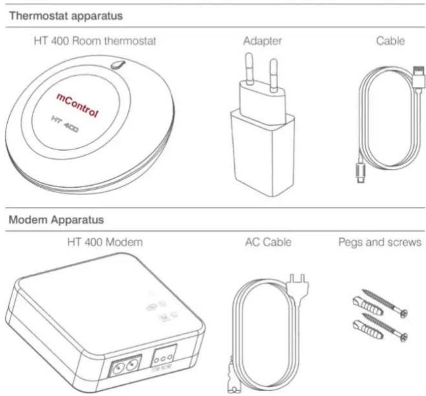
1.5 TECHNICAL DATA
Room Thermostat Technical Data
| Feeding Voltage | 5V (DC) |
| Load Current | 250 mA maximum |
| Dimensions | 90mm / 45mm |
| Measurement Accuracy | 0.1°C |
| Temperature Setting Accuracy | 0.1°C – 1.0°C |
| Working Accuracy | 0.5°C |
| Operating Temperature | (-10°C) – (+50°C) |
| Storage Temperature | (-20°C) – (+60°C) |
Modem Technical Data
| Feeding Voltage | 220V (AC) |
| Dimensions | 85mm / 90mm / 28.5mm |
| Relay NO Switching Current | 10A (220V AC) |
| Operating Temperature | (-10°C) – (+50°C) |
| Storage Temperature | (-20°C) – (+60°C) |
1.6 HT400 RECEIVER

natural_image
Line drawing of a rectangular electronic device with buttons and ports (no text or symbols)
1-Sync Button:
Syncs modem and room thermostat.
2-Manual Button:
Deactivates modem and allows you to use boiler manually.

3-Modem AC Cable Input
4-Boiler Connection Cable Input
1.7 HT400 RECEIVER PLACEMENT
The important thing to note in the HT 400 modem placement is that avoiding physical contact with boiler and protecting against materials such as liquid, dust etc. You can place your modem in boiler's cabinet without physical contact with boiler or mount modem to wall by using Modem.
Connection Scheme
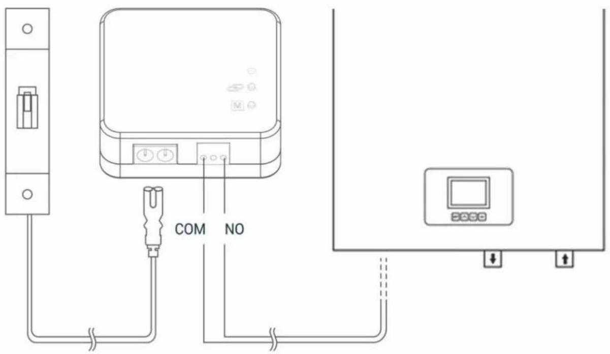
1.8 HT400 RECEIVER SETUP
- First, shut down electrical current which your boiler is connected (fuse, power outlet etc.)
- Connect one of the boiler connection cable to HT 400 Modem as shown in the Connection Scheme.
- Connect other boiler connection cable end to boiler's room thermostat input as shown in the boiler's user manual.
- Input Modem AC cable first to modem than to plug. If there is no plug near your boiler, you can connect AC cable to your boiler's connection fuse.
• After finishing connections, turn on electrical current first, then turn on your boiler. - If you want to deactivate your modem, press manual button then you should see orange light on modem. After being sure that your boiler is working, press same button and see orange light disappeared.
- Setup Room Thermostat to sync modem with room thermostat.
Attention: Only persons who have got Professional Competence should make operations electric wiring or boiler setup.
At the following link you can watch a video that describes in detail the procedure for connecting the receiver:
- h ps://www.youtube.com/watch?v=EPZexrCDGdA
- or on the Mikoterm YouTube channel which you can reach through our site
- or by loading the following QR code:


2. HT400 SMART ROOM THERMOSTAT RESET AND SYNCHRONIZATION

Chapter 2.2 describes the synchronization procedure in more detail

1-Wi-Fi Reset Button:
Pressing button resets Wi-Fi connection and forgets connection information. This allows you to connect new network.
2-Sync Button:
Used to sync thermostat with modem.

natural_image
Line drawing of a dome-shaped container with a labeled part (3), no text or symbols present3-Thermostat AC Cable Input
2.1 HT 400 ROOM THERMOSTAT PLACEMENT
Place your room thermostat in a room where you most use it as your living area. For example: living room. Avoid installing the room thermostat where there is a lot of air circulation such as door entry or window edges. Also, do not place in places near heat units (central heating system, fireplace, etc.) and places that receive direct sunlight. We recommend that the room thermostat be placed at an altitude of 50 cm to 150 cm from the floor. You can try to place few places to find the most suitable place.

2.2 HT 400 ROOM THERMOSTAT SETUP

- To start setup and mounting, first scan QR Code below via your smartphone. You can install application to your smartphone with that code (You may need QR Code Reader App regarding to your phone's model and brand) Note: To get further information about mounting and setup please visit www.generallife.com.tr/kurulum/ht-400
- Plug in adapter to HT400 and than wait for light to come on. After the light starts blinking purple, the HT 400 smart setup will be ready.
- You will receive confirmation mail after you completed signing up.
- If you confirm the incoming mail, the application will automatically have directed to setup page.
- Perform the instructions on the Setup page in order and complete setup.
- When syncing the modem with the thermostat, be sure to press the sync button on the modem and wait for the modem light to blink green. Push sync button on thermostat for 2 seconds. The modem will alert you with sound and the light will be solid green. Now the room thermostat and the modem are synced with each other.
At the following link, you can watch a video that describes in detail the procedure for installing the application and synchronizing the thermostat:
- h ps://www.youtube.com/watch?v=vjmHbMTPg9g&t
- or on the Mikoterm YouTube channel which you can reach through our site
- or by loading the following QR code:

Note: in order to synchronize the thermostat with the home network, you must make sure that the frequency of the Wi-Fi network is 802.11 b / g / n @ 2.4GHz. It is also important that the code for the home router with which the thermostat is synchronized does not have characters and punctuation marks such as (= + _ #.!?, @% \$ ,/> <* -), but only letters or numbers.
Note: If you have started the thermostat synchronization process on one phone and you have not synchronized the thermostat correctly, you cannot synchronize the thermostat on the other phone until you uninstall the application on the previous one or synchronize the thermostat correctly.
Important: there is only one administrator account for thermostat control and you can add 4 more users (the procedure for adding users is described in chapter 3.6).
2.3 LED LIGHT COLOR EXPLANATIONS - MODEM
| Fixed Green | Modem synced with thermostat and works properly. |
| Green Flashing | Pressed to Modem sync button and waiting for thermostat sync signal. |
| Red | Modem has energy but no thermostat synced. |
| Red Flashing | Boiler shut down because no signal from thermostat more than 22 minute. |
| Orange | On Manual Mode. |
2.4 LED LIGHT COLOR EXPLANATIONS - ROOM THERMOSTAT
| White | The device is turning on. |
| Yellow | Wi-Fi Module is turning on or modem syncing in progress. |
| Green | Wi-Fi turned on |
| Red | Wi-Fi Error |
| Purple Flashing | Access point is active. |
| Pink | Can't connect to Wi-Fi network. |
| Green Flashing | Waiting for modem sync. |
| Blue | Boiler is OFF |
| Orange | Boiler is ON |
| Blue Flashing | Boiler is OFF and no internet connection. |
| Orange Flashing | Boiler is ON and no internet connection. |
3. THERMOSTAT CONTROL THROUGH APPLICATION
NOTE: if your mobile phone is set to Serbian and the application will be installed in Serbian. While if your mobile is set to English or any other language, an English language application will be installed during installation.
After the correct installation of the mC HT400 application, connection and synchronization, starting the mC HT400 application, you will get image 1 on the phone screen. If you see information on the phone screen that you do not have a connection to the thermostat, it means.
To activate the boiler to heat, you must increase the set temperature, which in image 1 is 19 °C, using the up arrow. The set temperature must be higher than the current room temperature, which in image 1 is 22 °C. When you increase the set temperature, the fire will start to glow orange - image 2.
If you want the boiler to stop heating, use the down arrow to reduce the set temperature to be lower than the current room temperature - image 1.
There are 6 operating modes:
- Manual mode
- Home mode
- Outside mode
- Sleep mode
- Program mode
- Location mode
Click on modes a selection menu for operating mode will appear - image 2.
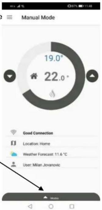
image 1
Explanation of symbols:

Connec on quality

Loca on of the thermostat that was installed during

Weather forecast for the loca on where the thermostat is installed

The user who currently opera ng the thermostat

Arrow to increase the set temperature

Arrow to decrease the set temperature
19.0°
Set temperature

22.0°
Current room temperature

The boiler does not work (set temp. Is lower than current)

The boiler is running (set temp. Is higher than current)

image 2
3.1 MODES
By clicking on one of the modes from image 2, the thermostat switches the operation to the selected mode (pictures 3,4,5,6,7,8).

pie
| Category | Value | |---|---| | Angle | 19.0° | | Angle | 22.0° | Good Connection Location: Home Weather Forecast: 11.6 °C User: Milan Jovanovicimage 3 – manual mode

pie
| Category | Value | | ------------------ | ------ | | Good Connection | 24.0° | | Location: Home | | | Weather Forecast | 9.8 °C | | User: Milan Jovanovic | |image 4 – home mode
pie
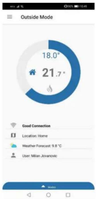
| Category | Value | |---|---| | Home | 18.0° | | Jovanovic | 21.7° | | Location: Home | - | | Weather Forecast: 9.8 °C | - | | User: Milan Jovanovic | - | | Nodes | - |image 5 – outside mode

pie
| Sleep Mode | Hours | | :--- | :--- | | 20.0° | 21.9° | | 20.0° | 20.0° |image 6 – sleep mode
pie
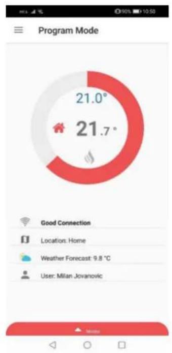
| Category | Value | |---|---| | Good Connection | 21.0° | | Location: Home | 21.7° | | Weather Forecast: 9.8 °C | 21.7° | | User: Milan Jovanovic | 21.7° |image 7 – program mode

pie
| Location Mode | Value | | :--- | :--- | | Home | 24.0° | | Outdoor | 21.7° | Location: Home Weather Forecast: 9.8 °C User: Milan Jovanovicimage 8 – loca on mode
3.2 OPERATING MODE ADJUSTMENT
To adjust the operating mode parameters, go to the settings by clicking on the menu icon - image 9, after which the image application menu - 10 opens. By selecting modes / modes, you enter the operating mode settings - image 11. Here you can set the temperature for each operating mode individually, so that when you select a specific operating mode (image 3,4,5,6,7,8) the thermostat will operate according to the settings you set as in image 11. Also if you want to reset the operating mode parameters factory settings, select "return to factory settings".
To specify the settings for the location mode, go to "change smart location settings", after which the page for setting the smart location will open - image 12.

pie
| Angle | Value | |-------|-------| | 23.0° | 23.0° | | 21.6° | 21.6° |image 9
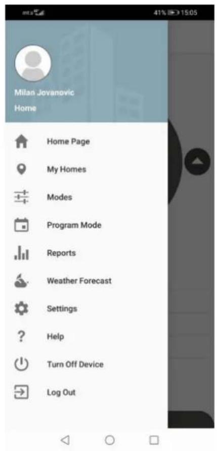
image 10
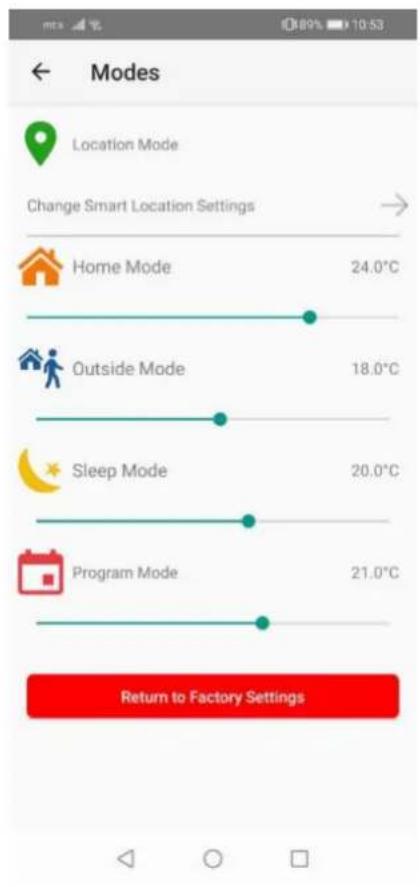
image 11
3.3 LOCATION MODE
On the smart location setting page, you can specify the distance (circle radius) from your station (thermostat). The location mode of the thermostat works so that when you enter within the circuit you set by setting the distance, the thermostat will automatically set the boiler one temperature and when you leave the circuit another temperature. In the example in image 12, a radius of 5 km is given, where when you enter the set circuit, the temperature set by the thermostat to the boiler is 24 °C, while when you leave the circuit, the thermostat will set the boiler a temperature of 18 °C.
NOTE: in order for the location mode to work in addition to the set parameters, you need to turn on the location on your phone (image 13) and the location mode on the application for mC HT400 (image 8).
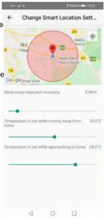
image 12

image 13

3.4 PROGRAM MODE
To enter the settings for the program mode, you need to select the program mode / program mode option in the main menu (image 10), after which the page for setting the program mode of the thermostat will open - image 14. To set the program mode, first select the day for which you want to make the settings (you can also select several days), and then click on + (image 15). After that, the option for setting the temperature opens - image 16. Set the temperature and time, then confirm with save (image 17). After saving the set values, you can perform an inspection - image 18. If you want to delete the default values, press delete / delete, image - 19, after which a window will open to select the day for which you want to delete the settings - image 20. Select the day and confirm remove - image 21.
NOTE: in order for the program mode to function properly, it is necessary to set a minimum of two temperature changes in one day (image 18) and to set the program mode to be switched on (image 7).

image 14
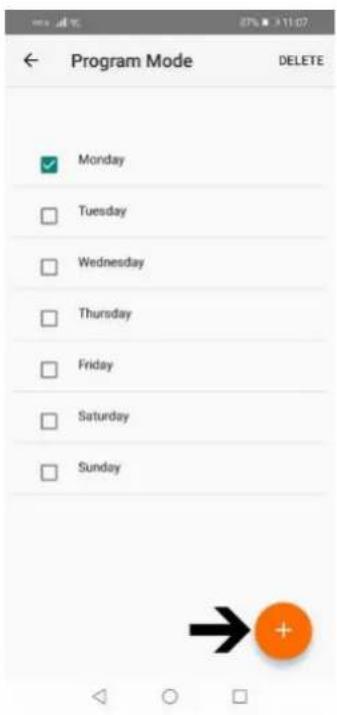
image 15

image 16
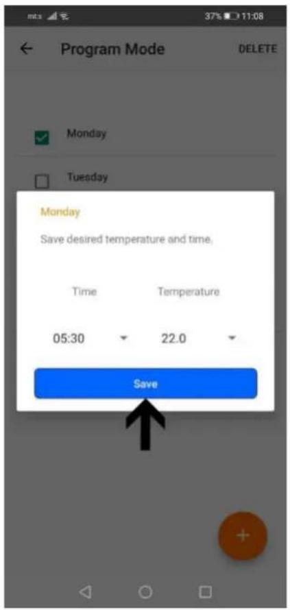
image 17

image 18
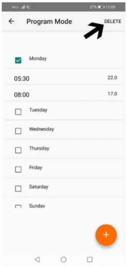
image 19

image 20
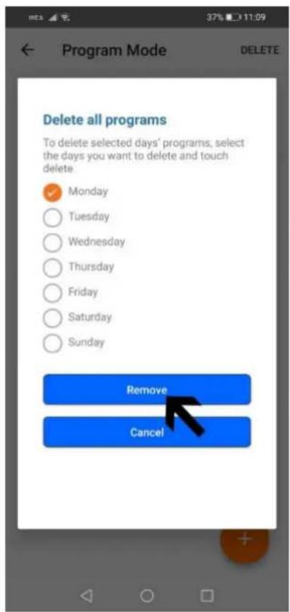
image 21
3.5 MANUAL, HOME, SLEEP AND OUTSIDE MODES

Manual mode allows you to adjust the current temperature you want in your home using the "up" or "down" arrows. Active manual mode (image 2 and 3).

Home mode is used when you are at home and a temperature of 23 °C is recommended. The temperature is set by selecting the modes / modes option (image 11). Active home mode image 4.

The sleep mode allows you to sleep comfortably with the set temperature you want. You can use this mode between 23:00 and 07:00, which is the usual bedtime. The suggested temperature value is 16. The temperature is set by selecting the modes / modes option (image 11). Active sleep mode image 6.

Outside mode is recommended when you are away from home for a short or long time. The temperature is set by selecting the modes / modes option (image 11). Active outside mode image 5.
3.6 OTHER OPTIONS (MAIN MENU)
Home page - takes you to the active mode (image 3-8).
My homes - takes you to your stations (thermostats) that you have activated on the mC HT400 application (there can be more than one station). By clicking on the station (image 22) and details (image 23) you enter the settings that allow you to add users, replace the profile photo of the station, change the location name, resynchronize and delete the station (image 24 and 25). In case you have more than one station, first select the station by clicking on the station you want to make changes to, then on details select the station if it is not already selected (image 23a).
Add a new (invited) user in option my homes
To add a user, select the add user option, after which a window for adding a new user's e-mail will open (image 26). After adding a new user's e-mail, the invited user can log in to the mC HT400 application on his phone via the invited user option (image 27), by entering his name and surname in the open fields, the email address with which the account administrator reported it and password (the password is determined by the invited user) - image 28. Then accept the terms of use and confirm on "sing up". Upon completion of the application, the invited user will receive an email with a confirmation link. By clicking on the send link, the invited user can access his account (the application will transfer-log it himself or he can log in via the log in option in image 27).

image 22
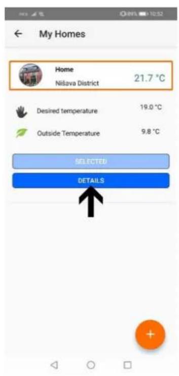
image 23

image 23 a
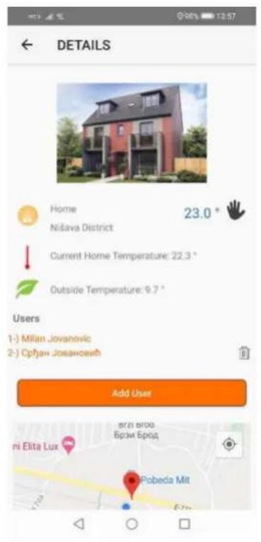
image 24

image 25

image 26
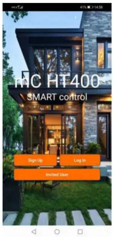
image 27

image 28
Reports - provides an overview of the previous operation of the thermostat where weekly, monthly or 6-monthly reports can be viewed (image 29).
Weather forecast - provides a daily and weekly overview of weather conditions for the place where your thermostat is located (image 30).
Help - you can see brief explanations for handling the mC HT400 application (image 31).

line
| Date | Temperature Average | MOTION SET Operating Status | |------|---------------------|------------------------------| | 10 | 8 | 0.025 | | 20 | 9 | 0.025 | | 30 | 10 | 0.025 | | 40 | 11 | 0.025 | | 50 | 12 | 0.025 | | 60 | 13 | 0.025 | | 70 | 14 | 0.025 | | 80 | 13 | 0.025 | | 90 | 12 | 0.025 | | 100 | 11 | 0.025 | | 110 | 10 | 0.025 | | 120 | 9 | 0.025 | | 130 | 8 | 0.025 | | 140 | 7 | 0.025 | | 150 | 6 | 0.025 |image 29
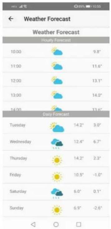
image 30

image 31
Settings - is an option where you can adjust the thermostat calibration and temperature sensitivity. You can also turn on / off the light on the thermostat display (screen light). You can change the image or user name via profile settings (image 32 and 33).
Turn (off / on) the device - offers the possibility to turn the thermostat on or off (image 34).
Log out - exit from your account and returns to the home page of the application (image 27).

image 32

image 33
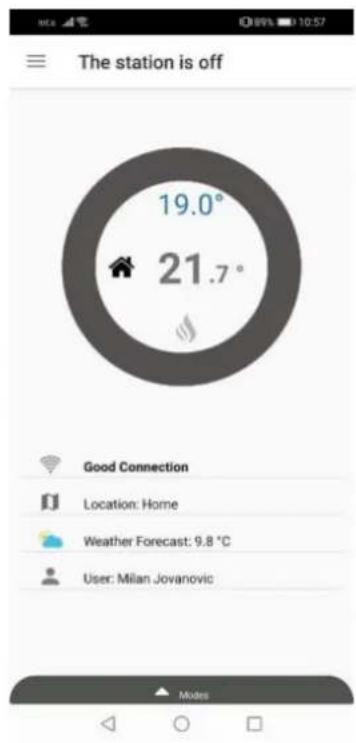
image 34
4. WARRANTY CONDITIONS AND STATEMENTS
4.1 DECLARATION OF CONFORMITY
Brand: mControl
Product Name: HT400
Product Type: Smart Room Thermostat
The product is connected wirelessly at 2.4 Ghz internet and periodically shares the temperature and status information with the server on the internet.
Compatible Directives:
Radio and Telecommunication Terminal Equipment Regulation 2014/53/EU (R&TTE/RED EN 301 489-1 V2.1.1:2017, EN 300 220-1 V3.1.1:2017, EN 301 489-3 V2.1.1:2017, EN 300 220-2 V3.1.1:2017, EN 62479: 2010, EN 60730-2-9:2010, EN 60730-1:2011)
Electromagnetic Compatibility Regulation 2014/30/EU (EMC EN 61000-6-3: 2007 + A1:
2011, EN 61000-6-1: 2007
Low Voltage Directive 2014/35/EU (LVD EN 60730-2-9:2010, EN 60730-1:2011).
4.2 WARRANTY CONDITIONS
-
Warranty starts at the delivery date of devices and equipments and warranted against manufacturing defect for 2 years.
-
Devices and equipments are delivered to customers in operation. Mounting and other connections will be additional fee for service.
-
Devices will maintenance and repair in our factory and should send by contracted transportation company. For out services, transportation and accommodation of service personnel are covered by customers. Overtime is added on service charge and is received as cash proceeds.
-
Maintenance of devices and equipments will be in our factory. For device maintenance, the round travel fares are covered by customers.
-
If devices are malfunction in warranty duration, devices will be inspected in our factory to find out whose responsibility (manufacturer or customer) and will announce to user by report.
-
Devices, which malfunctioned in warranty duration and found out it is responsibility of manufacturer, customer can demand new product or repair which all costs will fulfilled by manufacturer regarding to cost is not higher than device.
-
After inspection of malfunction and detected that, it is customer's fault, repair cost of the device which still in warranty duration will be customer's responsibility.
-
Customers should be aware of damages (if there is any) of product and warn manufacturer since the day warranty duration starts. If customer do not warn manufacturer with knowledge of damage, customer lose the rights of article 6.
-
Devices and equipments should be used as specified in User's Manual if not used as specified, products are out of warranty.
-
If products damaged, scratched or cracked by customer. The products will be out of warranty conditions.
-
Damages/Malfunctions because of using other brand's and model's devices and equipments without knowledge of manufacturer are out of warranty.
-
The arising depredation owing to working in humid and acidic places and result of rusting, oxidation is out of warranty.
-
The transport damage is out of warranty. Customers can take a transportation insurance.
-
Damages by virtue of grid voltage are out of warranty.
-
Damages because of force majeure like flood, earthquake, fire etc. are out of warranty.
-
All parts of the product are under warranty of our company.
-
If product breaks down and gets fixed in warranty duration, duration of maintenance adds to the warranty duration. Products repairment can't exceed 20 work days. This duration starts when the product's problems are reported to the seller, agency, producer or the importer if there is no service station. Consumer can report the problem by; fax, e-mail, registered and reply paid letter or a similar way. If a conflict happens, the consumer has the responsibility of proofing it. If the problem can't be solved more than 10 days the producer or importer has to supply a similar device until end of the reparation. If the product breaks down because of material, label or mounting faults in the warranty duration, firm won't demand label costs, changing parts or any other kind of charge for repairment.
-
Despite consumers rights of maintenance;
a. If the product breaks down for 4 times in a year or 6 times in warranty duration and these problems effects main purpose of the product. (starting from delivery time during warranty.),
b. Exceeding the maximum repairing term,
c. In the case of not existing service station, determining that repairment is not possible with the report compiled by respectively service station's seller, dealer, agency, legation, importer or manufacturer.
Warranty document should be kept by customer until warranty duration is finished. If warranty is lost there will be no replacement. All maintenance and repair cost is responsibility of customer in case of warranty document lost.
- THE CONTENT:
- WHAT IS SMART ROOM THERMOSTAT?
- HT400 SMART ROOM THERMOSTAT RESET AND SYNCHRONIZATION
- THERMOSTAT CONTROL THROUGH APPLICATION
- WARRANTY CONDITIONS AND STATEMENTS
- HOW DOES SMART ROOM THERMOSTAT WORKS?
- WHAT ARE ADVANTAGES OF SMART ROOM THERMOSTAT HT400?
- RULES TO BE CONSIDERED FOR SAFETY
- HT400 AND EQUIPMENTS
- TECHNICAL DATA
- HT400 RECEIVER
- HT400 RECEIVER PLACEMENT
- Connection Scheme
- HT400 RECEIVER SETUP
- 1-Wi-Fi Reset Button:
- 2-Sync Button:
- 3-Thermostat AC Cable Input
- HT 400 ROOM THERMOSTAT PLACEMENT
- HT 400 ROOM THERMOSTAT SETUP
- Explanation of symbols:
- MODES
- OPERATING MODE ADJUSTMENT
- LOCATION MODE
- PROGRAM MODE
- MANUAL, HOME, SLEEP AND OUTSIDE MODES
- OTHER OPTIONS (MAIN MENU)
- Add a new (invited) user in option my homes
- DECLARATION OF CONFORMITY
- WARRANTY CONDITIONS
Brand : Mikoterm
Model : HT 400
Category : Thermostat