SWR2310-28GT - Network switch YAMAHA - Free user manual and instructions
Find the device manual for free SWR2310-28GT YAMAHA in PDF.

| Product Type | Network Switch |
| Brand | Yamaha |
| Model | SWR2310-28GT |
| Form Factor | 1U Rackmount |
| Dimensions (W x D x H) | 440 x 200 x 44 mm |
| Weight | 3.5 kg |
| Power Supply | AC 100-240V, 50/60Hz, 30W |
| Ports | 24 x Gigabit Ethernet (RJ45), 4 x SFP Uplink |
| Switching Capacity | 56 Gbps |
| MAC Address Table | 16K entries |
| VLAN Support | Yes, up to 4K VLANs |
| QoS | IEEE 802.1p, 8 priority queues |
| Link Aggregation | IEEE 802.3ad, up to 8 groups |
| Management | Web GUI, CLI, SNMP, Telnet, SSH |
| Operating Temperature | 0°C to 40°C |
| Humidity | 10% to 90% non-condensing |
| Maintenance | Clean exterior with dry, soft cloth; avoid liquids |
| Safety | Keep away from moisture, do not block vents |
| Spare Parts | Not user-serviceable; contact Yamaha support |
| Repairability | Device must be returned to authorized service center |
Frequently Asked Questions - SWR2310-28GT YAMAHA
User questions about SWR2310-28GT YAMAHA
0 question about this device. Answer the ones you know or ask your own.
Ask a new question about this device
Download the instructions for your Network switch in PDF format for free! Find your manual SWR2310-28GT - YAMAHA and take your electronic device back in hand. On this page are published all the documents necessary for the use of your device. SWR2310-28GT by YAMAHA.
USER MANUAL SWR2310-28GT YAMAHA
The above warning is located on the top of the unit.

text_image
ATTENTION RISQUE DE CHOC ELECTRIQUE-NE PAS OUVRIR ATTENTION : POUR RÉDUIRE LES RISQUES D'ÉLECTROCUTION, NE PAS RETIRER LE CAPOT (OU LE DOS). NE CONTIENT PAS DE PIÈCES NÉCESSITANT L'INTERVENTION DE L'UTILISATEUR. POUR TOUTE INTERVENTION, FAIRE APPEL À DES PROFESSIONNELS QUALIFIÉS.The lightning flash with arrowhead symbol within an equilateral triangle is intended to alert the user to the presence of uninsulated “dangerous voltage” within the product’s enclosure that may be of sufficient magnitude to constitute a risk of electric shock to persons.
The exclamation point within an equilateral triangle is intended to alert the user to the presence of important operating and maintenance (servicing) instructions in the literature accompanying the product.
IMPORTANT SAFETY INSTRUCTIONS
1 Read these instructions.
2 Keep these instructions.
3 Heed all warnings.
4 Follow all Instructions.
5 Do not use this apparatus near water.
6 Clean only with dry cloth.
7 Do not block any ventilation openings. Install in accordance with the manufacturer's instructions.
8Do not install near any heat sources such as radiators, heat registers, stoves, or other apparatus (including amplifiers) that produce heat.
9 Do not defeat the safety purpose of the polarized or grounding-type plug. A polarized plug has two blades with one wider than the other. A grounding type plug has two blades and a third grounding prong. The wide blade or the third prong are provided for your safety. If the provided plug does not fit into your outlet, consult an electrician for replacement of the obsolete outlet.
10 Protect the power cord from being walked on or pinched particularly at plugs, convenience receptacles, and the point where they exit from the apparatus.
11 Only use attachments/accessories specified by the manufacturer.
12 Use only with the cart, stand, tripod, bracket, or table specified by the manufacturer, or sold with the apparatus. When a cart is used, use caution when moving the cart/apparatus combination to avoid injury from tip-over.
13 Unplug this apparatus during lightning storms or when unused for long periods of time.
14 Refer all servicing to qualified service personnel. Servicing is required when the apparatus has been damaged in any way, such as power-supply cord or plug is damaged, liquid has been spilled or objects have fallen into the apparatus, the apparatus has been exposed to rain or moisture, does not operate normally, or has been dropped.

WARNING
TO REDUCE THE RISK OF FIRE OR ELECTRIC SHOCK, DO NOT EXPOSE THIS APPARATUS TO RAIN OR MOISTURE.
PRÉCAUTIONS CONCERNANT LA SÉCURITÉ
This product, when installed as indicated in the instructions contained in this manual, meets FCC requirements. Modifications not expressly approved by Yamaha may void your authority, granted by the FCC, to use the product.
-
IMPORTANT: When connecting this product to accessories and/or another product use only high quality shielded cables. Cable/s supplied with this product MUST be used. Follow all installation instructions. Failure to follow instructions could void your FCC authorization to use this product in the USA.
-
NOTE: This equipment has been tested and found to comply with the limits for a Class A digital device, pursuant to Part 15 of the FCC rules. These limits are designed to provide reasonable protection against harmful interference when the equipment is operated in a commercial environment. This equipment generates, uses and can radiate radio frequency energy and, if not installed and used in accordance with the instruction manual, may cause harmful interference to radio communications. Operation of this equipment in a residential area is likely to cause harmful interference in which case the user will be required to correct the interference at his own expense.
(class A)
COMPLIANCE INFORMATION STATEMENT (Supplier's declaration of conformity procedure)
Responsible Party: Yamaha Corporation of America
Address: 6600 Orangethorpe Ave. Buena Park CA90620
Telephone: 714-522-9011
Type of Equipment: L2 SWITCH
Model Name: SWR2310-28GT, SWR2310-18GT, SWR2310-10G
This device complies with Part 15 of the FCC Rules.
Operation is subject to the following conditions:
1) this device may not cause harmful interference, and
2) this device must accept any interference received including interference that may cause undesired operation.
See user manual instructions if interference to radio reception is suspected.
(FCC SDoC)
PLEASE READ CAREFULLY BEFORE PROCEEDING
Please keep this manual in a safe place for future reference.
This product is an intelligent L2 switch with optimal functionality for Dante.
Do not use for any purposes other than the one intended. Those who are unfamiliar with handling or those who can not handle according to this manual such as children, should be supervised by responsible persons to ensure safety.

WARNING
Always follow the basic precautions listed below to avoid the possibility of serious injury or even death from electrical shock, short-circuiting, damages, fire or other hazards. These precautions include, but are not limited to, the following:
If you notice any abnormality
- If any of the following problems occur, immediately turn off the power switch and disconnect the electric plug from the outlet.
- The power cord or plug becomes frayed or damaged.
- Unusual smells or smoke are emitted.
- Some object, or water has been dropped into the product.
- There is a sudden loss of sound during use of the product.
- Cracks or other visible damage appear on the product.
Then have the product inspected or repaired by qualified Yamaha service personnel.
Power supply/power cord
- Do not place the power cord near heat sources such as heaters or radiators, and do not excessively bend or otherwise damage the cord, place heavy objects on it, or place it in a position where anyone could walk on, trip over, or roll anything over it.
- Only use the voltage specified as correct for the product. The required voltage is printed on the name plate of the product.
- Use only the supplied power cord/plug. If you intend to use the product in an area other than in the one you purchased, the included power cord may not be compatible. Please check with your Yamaha dealer.
- Check the electric plug periodically and remove any dirt or dust which may have accumulated on it.
- Make sure to fully insert the electric plug to prevent electric shocks or fire.
- When setting up the product, make sure that the AC outlet you are using is easily accessible.
If some trouble or malfunction occurs, immediately disconnect the plug from the outlet. As long as the power cord is not unplugged from the wall AC outlet, the product will not be disconnected from the power source. - Remove the electric plug from the outlet when the product is not to be used for extended periods of time.
- Do not touch the product or the electric plug during an electrical storm.
- Be sure to connect to an appropriate outlet with a protective grounding connection. Improper grounding can result in electrical shock, fire, or damage.
Do not open
- This product contains no user-serviceable parts. Do not attempt to disassemble the internal parts or modify them in any way.
Water warning/Fire warning
- Do not expose the product to rain, use it near water or in damp or wet conditions, or place on it any containers (such as vases, bottles or glasses) containing liquids which might spill into any openings.
- Never insert or remove an electric plug with wet hands.
- Do not place any burning items or open flames near the product, since they may cause a fire.

CAUTION
Always follow the basic precautions listed below to avoid the possibility of physical injury to you or others. These precautions include, but are not limited to, the following:
Power supply/power cord
- When removing the electric plug from the product or an outlet, always hold the plug itself and not the cord. Pulling by the cord can damage it.
Location and connection
- Do not place the product in an unstable position or a location with excessive vibration, where it might accidentally fall over and cause injury.
-
Keep the device and small parts out of reach of children, to keep them from putting their fingers into openings on the product and accidentally being injured. This product is not suitable for use in locations where children are likely to be present.
-
Do not block the vents. This product has ventilation holes at the top (SWR2310-10G only)/sides to prevent the internal temperature from becoming too high. In particular, do not place the product on its side or upside down. Inadequate ventilation can result in overheating, possibly causing damage to the product(s), or even fire.
- When installing the product:
- Do not cover it with any cloth.
- Do not install it on a carpet or rug.
- Make sure the top or side surface faces up; do not install on its front, rear, or upside down.
- Do not use the product in a confined, poorly-ventilated location.
Inadequate ventilation can result in overheating, possibly causing damage to the product(s), or even fire.
- When using the separately sold WK-SWR wall mount accessory, do not install the SWR2310-18GT, SWR2310-10G on a wall or ceiling that is more than 2 meters high. The product might fall, causing malfunction or injury.
- If the product is mounted in an EIA standard rack, carefully read the section "Please read before mounting the unit into a rack" on page 20. Inadequate ventilation can result in overheating, possibly causing damage to the product(s), malfunction, or even fire.
- Do not place the product in a location where it may come into contact with corrosive gases or salt air. Doing so may result in malfunction.
- Before moving the product, remove all connected cables.
- Always consult qualified Yamaha service personnel if the product installation requires construction work, and make sure to observe the following precautions.
- Choose mounting hardware and an installation location that can support the weight of the product.
- Avoid locations that are exposed to constant vibration.
- Use the required tools to install the product.
- Inspect the product periodically.
PA11-2/4
Maintenance
- Remove the power plug from the AC outlet when cleaning the product.
Handling caution
- Do not insert your fingers or hands in any gaps or openings on the product (vents, ports, panel, etc.).
- Do not rest your weight on the product or place heavy objects on it.
- Do not look into the optical emitter when a separately sold SFP module (SFP-SWRG-SX, SFP-SWRG-LX) and/or SFP+ module (SFP-SWRT-SR, SFP-SWRT-LR) is installed. The separately sold SFP/SFP+ modules are class 1 laser devices. They may emit laser beams invisible to the eye. If the laser beam enters your eye, your eyesight might be damaged.
Backup battery
- Do not replace the backup battery by yourself. Doing so may cause an explosion and/or damage to the product(s). When the backup battery needs to be replaced, contact your Yamaha dealer and have qualified Yamaha service personnel replace the backup battery.
Yamaha cannot be held responsible for damage caused by improper use or modifications to the product, or data that is lost or destroyed.
To avoid the possibility of malfunction/ damage to the product, damage to data, or damage to other property, follow the notices below.
Handling and maintenance
- Do not touch the interior of a port with your fingers or any metallic object. Doing so might cause malfunctions.
- Do not use the product in a location exposed to direct sunlight (such as in a car during the day), in a location of extreme heat such as near a stove, in a location of extreme cold, or in a location of excessive dust or vibration. Failure to observe this precaution could cause the product's panel to deform, its interior components to malfunction, or its operation to become unstable.
- Do not place vinyl, plastic or rubber objects on the product, since this might cause alteration or discoloration of the panel.
- When cleaning the product, use a dry and soft cloth. Do not use paint thinners, solvents, cleaning fluids, or chemical-impregnated wiping cloths, since this might cause alteration or discoloration.
- Condensation can occur in the product due to rapid, drastic changes in ambient temperature—when the product is moved from one location to another, or air conditioning is turned on or off, for example. Using the product while condensation is present can cause damage. If there is reason to believe that condensation might have occurred, leave the product for several hours without turning on the power until the condensation has completely dried out.
- Drain all static electricity from your clothing and body before handling this product. Static electricity can damage this product. Touch an exposed metal part of the host device or other grounded object beforehand.
-
Do not install the product in a location where magnetic fields are strong. Otherwise, it might cause the product to malfunction.
-
Do not connect any noise generating devices on the same power line as the product. Failure to observe this precaution could result in a malfunction or damage to the product.
- Do not locate any connected LAN cables close to the power cord. Otherwise, high voltage might be induced, resulting in malfunction.
- A 1000BASE-T connection will require an Enhanced Category 5 (CAT5e) or better LAN cable.
- Do not install any SFP module other than the separately sold SFP-SWRG-SX or SFP-SWRG-LX in an SFP port. Operation cannot be guaranteed if any SFP module other than the above is installed.
- Do not install any SFP+ module other than the separately sold SFP-SWRT-SR or SFP-SWRT-LR, any SFP module other than the SFP-SWRG-LX or SFP-SWRG-SX, or any direct attach cable other than the DAC-SWRT-3M or DAC-SWRT-1M in an SFP+ port. Operation cannot be guaranteed if any module or cable other than the above is installed.
- Attach the dust cover to SFP/SFP+ ports that are not in use. Failing to do so could allow foreign objects to enter, causing malfunctions. Keep the dust cover in a safe place so that it is not lost.
- The rubber feet included in this package can be attached to the product to prevent slippage when it is to be used on a slippery surface.
- Do not connect this product to public Wi-Fi and/or Internet directly. Only connect this product to the Internet through a router with strong password-protections. Consult your router manufacturer for information on security best practices.
Saving data
- This unit has a built-in backup battery that maintains time information for the data. When the backup battery runs down, the time information will be initialized, causing incorrect time information to be recorded in the log. If this occurs, contact your dealer or a Yamaha customer service center to have the backup battery replaced. The life span of the backup battery is approximately 10 years, but this may vary depending on the conditions of use. Set the clock after replacing the battery.
Functions/data bundled with the product
- This is a class A product. Operation of this product in a residential environment could cause radio interference.
About disposal
- This product contains recyclable components. When disposing of this product, please contact the appropriate local authorities.
About this manual
- The illustrations and screens as shown in this manual are for instructional purposes only.
- Windows is a registered trademark of Microsoft® Corporation in the United States and other countries.
- The company names and product names in this manual are the trademarks or registered trademarks of their respective companies.
- Software may be revised and updated without prior notice.
Open source software used in this product
- Please refer to the Yamaha Pro Audio website for the licensing terms. http://www.yamaha.com/proaudio/
Warning: Fiber Optic Port Safety
This product is intended to be installed in an UL certified Optical Transceiver Module, rated 3.3V, Laser Class 1, if need further assistance, please contact Yamaha Corporation for further information.
Conventions in this document
Company names and product names in this document are abbreviated as follows.
- Yamaha SWR2310-28GT, SWR2310-18GT, or SWR2310-10G L2 switch: this product
- 10BASE-T/100BASE-TX/1000BASE-T cable: LAN cable
- SFP-SWRT-SR or SFP-SWRT-LR: SFP+ module
- SFP-SWRG-SX or SFP-SWRG-LX: SFP module
- DAC-SWRT-3M or DAC-SWRT-1M: direct attach cable
Icons
Information that applies to the SWR2310-28GT, SWR2310-18GT, or SWR2310-10G is indicated by the following icons.
SWR2310-28GT
Indicates information that applies only to the SWR2310-28GT.
SWR2310-18GT
Indicates information that applies only to the SWR2310-18GT.
SWR2310-10G
Indicates information that applies only to the SWR2310-10GT.
Memo
An icon is not shown for information that is common to all models.
Contents
PRECAUTIONS 4
NOTICE 7
Introduction....10
Included items....10
Features....10
Separately sold items 11
Related software and documents 11
Controls and Connectors....12
Front Panel 12
Bottom panel / rear panel / side panel / top panel 14
Port indicators....19
Attaching the legs....20
Installation in a rack.... 20
Installation on a wall or ceiling.... 24
Settings.... 27
Make settings using the Web GUI 27
Making settings from the command line using the CONSOLE port.... 28
Connections 30
Initialization 34
Appendix.... 36
Hardware specifications.... 36
Dimensional diagram 38
RJ-45/DB-9 console cable pin configuration 39
Software license agreement 40
Index......42
Thank you for purchasing the Yamaha SWR2310-28GT, SWR2310-18GT, or SWR2310-10G intelligent L2 switch.
This product is an intelligent L2 switch with optimal functionality for Dante. This owner's manual is intended for installers and facility designers, and explains installation methods and settings. Please be sure to read this manual before you start using the product to take full advantage of its features. Please retain this manual in a safe location for future reference.
Included items
Verify that the following included items are present.
- Owner's manual (this document)
- Power cord
- Power cord clamp (used only for the included dedicated power cord)
• Legs (rubber feet) (4 pcs.)
- 19-inch rack mount hardware and screws (hardware: 2 pcs., screws: 8 pcs.)
SWR2310-28GT / SWR2310-18GT
These are required when installing this product in a 19-inch rack (1U size). For details on installation, refer to “Installing in a 19-inch rack” SWR2310-28GT SWR2310-18GT in “Installation.”
Features
- This product makes it easy to specify the recommended settings for stable operation of a Dante network (such as QoS, EEE, and IGMP Snooping).
- Multiple switches connected as a stack can be operated as a single virtual switch. The SWR2310-28GT is equipped with stack functionality.
- This product can ease your daily network maintenance and operation responsibilities.
You can use Yamaha LAN Monitor (application) to ascertain the network structure that is connected to this product and to monitor and manage the devices.
This product also supports performance management and damage management. All models regularly monitor the memory and CPU usage and the bandwidth usage of each port. The monitored data can be viewed in the Web GUI or backed-up to an SD card (sold separately).
The live/dead status of a network-connected terminal connected below this product can also be monitored using only this product.
- This product can operate in cooperation with an authentication server to authenticate terminals within the network.
This allows invalid terminals to be eliminated from the network.
Separately sold items
- RK-SWR rack mount accessory:
This is required when installing the SWR2310-10G in a 19-inch rack.
- WK-SWR wall mount accessory:
This is required when installing the SWR2310-10G or SWR2310-18GT on a wall or ceiling 2 m or less in height.
- SFP-SWRG-SX or SFP-SWRG-LX SPF module:
This is required when transmitting via 1000BASE-SX or 1000BASE-LX.
- SFP-SWRT-SR or SFP-SWRT-LR SFP+ module:
This is required when transmitting via 10GBASE-SR or 10GBASE-LR.
- DAC-SWRT-3M or DAC-SWRT-1M direct attach cable:
These are direct attach cables that provide SFP+ modules and copper cable in a single unit. By directly connecting between SFP+ ports, these allow a 10 gigabit Ethernet system to be constructed inexpensively, although with limited distance.
Related software and documents
- Yamaha LAN Monitor/Yamaha LAN Monitor user guide
This is a PC application used to monitor this unit's information and the entire network including all Dante devices on the Dante network, and the user guide for this application.
- Yamaha network device USB serial driver / Yamaha network device USB serial driver installation guide
This is a Windows driver that allows communication when the mini-USB CONSOLE port is connected via a USB cable to a computer, and the installation guide for this driver.
- Command reference
This explains the commands used when using the command line to make settings from a computer.
• Technical reference
This describes details of this product's functions.
This software and these documents can be downloaded from the following website. http://www.yamahaproaudio.com/
Controls and Connectors
Front Panel
SWR2310-28GT

text_image
YAMAHA www.SWR2310-20GT POWER ① ② ③ ④ ⑤ CONOLE USB #ONBD 137811135 17 18 21 23 2488101246 16 20 22 24 35 37 39 ⑥ ⑦ ⑧SWR2310-18GT

text_image
YAMAHA SWR2310-48GT POWER 1 2 3 4 5 CONSOLE USB B 1 3 5 7 9 11 13 15 2 4 6 8 10 12 14 16 M 18 7SWR2310-10G

text_image
YAMAHA USB SWR2310-40G POWER CONSOLE USB USBID ① ② ③ ④ ⑤ ⑥ ⑦ ⑧ ⑨①POWER indicator
Lights when power is provided to the unit.
| POWER indicator Status | |
| Unlit Power off | |
| Flashing (green) Power on, starting up | |
| Lit (green) Power on, normal | |
| Lit (orange) Power on, error occurred |

Caution
When an abnormal temperature is detected inside this product, the POWER indicator is lit orange. Reconsider the environment in which this unit is installed, and correctly install this unit so that its internal temperature is appropriate. You can also check this from Yamaha LAN Monitor or the Web GUI.
② mini-USB CONSOLE port
This is a mini-USB port for making settings. Use a USB cable to connect it to the USB port of a computer. Use a USB cable equipped with a USB Type A connector and a USB mini-B (5-pin) connector.
Memo
Use a cable that supports data transfer. Charge-only cables cannot be used.
③RJ-45 CONSOLE port
This is an RJ-45 port for making settings. Use an RJ-45/DB-9 console cable to connect it to the RS-232C connector (COM port) of the computer.
④microSD indicator
Indicates the connection and usage status of the microSD card.
| microSD indicator Status | |
| Unlit A microSD card is not inserted in the slot. | |
| Flashing green The microSD card is being accessed. | |
| Lit green A microSD card is inserted. | |

Caution
Do not remove the microSD card if this indicator is flashing green.
⑤microSD slot
A microSD card can be inserted in this slot.
⑥LAN ports
These ports support T10BASE-T, 100BASE-TX, and 1000BASE-T.
⑦SFP+ ports \$WR2310-28GT SWR2310-18GT
These ports support T10GBASE-SR, 10GBASE-LR, 1000BASE-SX, and 1000BASE-LX. Install an SFP+ module or SFP module sold separately by Yamaha. For the SWR2310-28GT or SWR2310-18GT, install a direct attach cable (DAC-SWRT-3M or DAC-SWRT-1M). For details on installing an SFP+ or SFP module, refer to "Installing an SFP module" (page 30) in "Connections." For details on installing a direct attach cable, refer to "Installing a direct attach cable" SWR2310-28GT The SWR2310-18GT also be used for stack connection. For details on stack connection, refer to "Making stack connections" SWR2310-28GT (page 33).
⑧Stack ID indicator SWR2310-28GT
This is a 7-segment display that indicates the stack ID when stack connection is used.
⑨SFP ports SWR2310-10G
These ports support 1000BASE-SX and 1000BASE-LX. Install an SFP module sold separately by Yamaha. For details on installing an SFP module, refer to “Installing an SFP module” (page 30) in “Connections.”
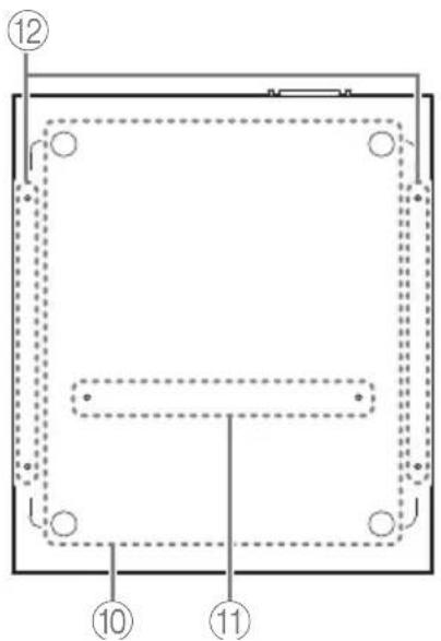
Bottom panel / rear panel / side panel / top panel
° Bottom panel
SWR2310-28GT

natural_image
Empty rectangular frame with four circular holes and a dashed border, no text or symbols present.SWR2310-18GT

natural_image
Pure diagram of a rectangular panel with circular holes and dashed outlines, labeled '0' and 'B' at bottom (no text or symbols within the diagram itself)SWR2310-10G
text_image
⑫ ⑩ ⑪⑩ Leg attachment guides
These indicate the locations at which the included legs are to be attached when the unit is installed in a level location. For details on installation, refer to "Attaching the legs" (page 20) in "Installation."
⑪ Rack mount accessory attachment holes SWR2310-10G
Use these holes to attach the RK-SWR rack mount accessory. For details on installation, refer to "Installing in a 19-inch rack" (page 2f) in "Installation."
⑫ Wall mount accessory attachment holes SWR2310-18GT SWR2310-10G
Use these holes to attach the WK-SWR wall mount accessory.
For details on installation, refer to “Installation on a wall or ceiling” SWR2310-18GT SWR2310-10G (page 24).
Notice
Magnet sheets are not supported, and should not be used.
Controls and Connectors
■ Rear panel
SWR2310-28GT
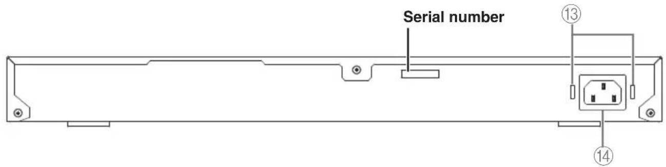
text_image
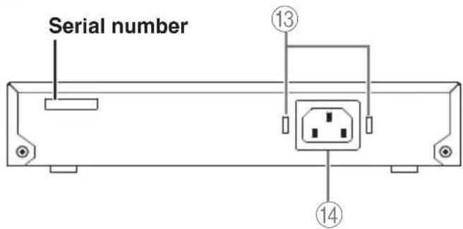
Serial number ⑬ ⑭ ⑮SWR2310-18GT

text_image
Serial number ⑬ ⑭ ⑭SWR2310-10G
text_image
Serial number ⑬ ⑭⑬Power cord clamp attachment holes
The included power cord clamp (C-shaped) can be attached here. For details on installation, refer to "Turning the power on" (page 33) in "Connections."
⑭Power supply inlet (three-pin connector, C14 type)
Insert the included power supply cord here.
Side panel
SWR2310-28GT
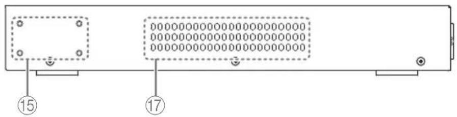
text_image
Diagram of a device rear panel with labeled ports and status indicatorsSWR2310-18GT
text_image
⑮ ⑰ ⑰SWR2310-10G
natural_image
Diagram of a computer monitor front panel with indicator lights and a numbered label (17) pointing to the side panel (no readable text or symbols beyond the number)■ Top panel
SWR2310-28GT

text_image
MAC address Serial number ⑯Controls and Connectors
SWR2310-18GT
text_image
MAC address Serial number ⑯SWR2310-10G

text_image
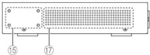
MAC address Serial number 16 17⑮Rack mount accessory attachment holes SWR2310-28GT SWR2310-18GT
These are used when installing this product in a 19-inch rack (1U). For details on installation, refer to "Installing in a 19-inch rack" SWR2310-28GT SWR2310-18GT (page 23) in "Installation."
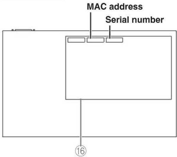
⑯Product label
This lists the model name, serial number, and MAC address etc. of this unit.
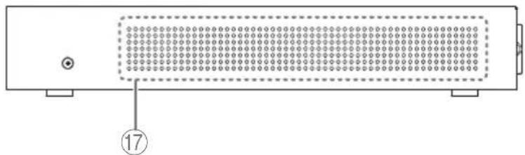
⑰Cooling vents
The holes in this product are cooling vents for intake of external air.

Warning
Do not block the cooling vents or place objects near them.
Doing so could cause fire or malfunctions.
Port indicators
These are indicators for the LAN ports and SFP/SFP+ ports, and indicate the state of each port in each mode.
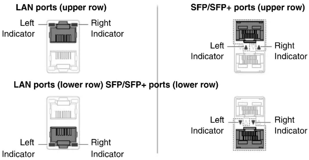
The indicators show the link status and connection speed of the LAN port or SFP/SFP+ port.
LAN ports
| Left indicator | Link status |
| Unlit | The link is lost.(unavailable) |
| Lit (green) | A link is established.(available) |
| Flashing (green) Data is flowing. Lit (green) | |
| Right indicator | Connection speed |
| Unlit | Not connected.Alternatively, connected by 10BASE-T. |
| Lit (orange) | Connected by 100BASE-TX. |
| Connected by 1000BASE-T. |
SFP/SFP+ ports
| Left indicator | Link status |
| Unlit | The link is lost.(unavailable) |
| Lit (green) | A link is established.(available) |
| Flashing (green) Data is flowing. | |
| Right indicator | Connection speed |
| Unlit Not connected. | |
| Lit (green) | Connected by 1000BASE-SX/LX or 10GBASE-SR/LR.If using the DAC-SWRT-3M or DAC-SWRT-1M, connected at 10 Gbps. |
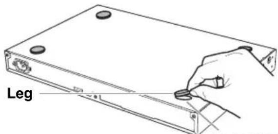
Attaching the legs
As shown in the illustration, attach the included legs in the positions of the leg attachment guides, and place the unit on a level location such as a desk.
text_image
Leg
text_image
端口 LegLeg attachment guides
Installation in a rack
Please read before mounting the unit into a rack
- This unit is warranted to operate in an ambient temperature range of 0–50 °C. If you install this unit along with other devices into an EIA-standard or JIS-standard rack, the temperature inside the rack may rise due to heat released from the other devices, resulting in poor performance of the unit. To prevent the temperature inside the unit from rising, mount the unit in the rack in accordance with the requirements below.
- If you plan to rack-mount the unit along with a device that tends to generate heat, such as an amplifier (excluding an XMV series), be sure to leave a gap of 1U or more from such devices. Also, be sure to maintain sufficient ventilation in this space by installing a ventilation panel or leaving it open.
- Open the rear panel of the rack, and place the rack at least 10cm (about four inches) away from the walls and ceiling to ensure sufficient ventilation. If you cannot open the rear panel of the rack, install a commercially-available forced ventilation device, such as a fan kit. If you install a fan kit, closing the rear panel may work better for heat dissipation purposes. For more information, refer to the owner's manual for the rack and/or fan kit.

Caution
If you plan to relocate the rack, be sure to first remove this unit from the rack.
If you move the unit while it is still installed in the rack, vibration or physical shock might deform or damage the rack mount accessory or rack mount hardware, causing injury. There is also a possibility that this unit might malfunction.
■ Installing in a 19-inch rack SWR2310-10G
The SWR2310-10G is installed using an RK-SWR rack mount accessory sold separately by Yamaha.
Installation
This section explains how to attach the unit in the middle block of a rack mount panel. Even if you plan to attach the unit in the left or right block, follow the procedure below.
Notice
If the supplied feet have already been attached to the unit, remove them.
1. Attaching the rack mount panel to the unit
Use the two screws supplied with the rack-mount accessory, attach the rack mount panel to the bottom panel of the unit.

Warning
When attaching this unit to the separately sold RK-SWR rack mount accessory, you must use the specified screws that are included with the rack mount accessory. If the unit falls, injury or damage might occur. This could also cause electric shock or malfunctions.

text_image
Rack mount panel ScrewsUse a Phillips screwdriver to firmly fasten the screws.
Installation in a rack
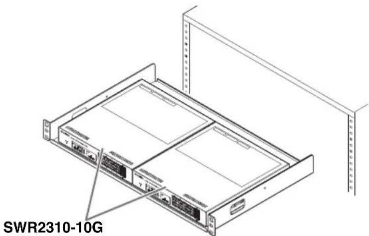
2. Install the rack mount panel to the 19-inch rack.
Using the screws that are included with the 19-inch rack (EIA standard 4 pcs., JIS standard 2 pcs.), fasten this unit to the 19-inch rack. Be sure to tighten the screws so that they will not get loosened.

text_image
[For an EIA standard rack] Screws supplied with the 19-inch rack [For a JIS standard rack] Screws supplied with the 19-inch rack SWR2310-10G 19-inch rack Rack mount panelYou can also mount two SWR2310-10G units as shown in the figure below.
text_image
SWR2310-10G
Caution
So as not to obstruct the cooling vents on the top panel of this unit, leave a gap when installing it in a 19-inch rack.
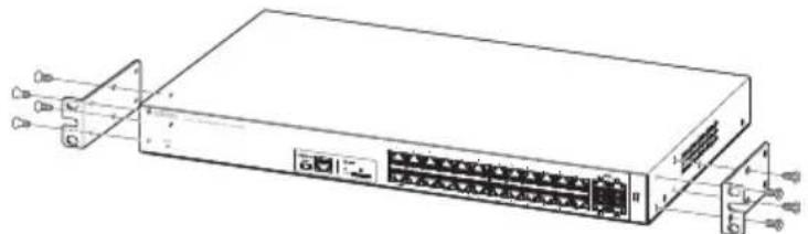
■ Installing in a 19-inch rack SWR2310-28GT / SWR2310-18GT
The SWR2310-28GT and SWR2310-18GT fit in a 19-inch rack mount 1U size. When installing them in a 19-inch rack, attach the included rack mount hardware (2 pcs.) using the included screws (8 pcs.). Here we explain using the SWR2310-28GT as an example.
natural_image
Line drawing of a network switch device with ports and connectors (no text or symbols)Use a Phillips screwdriver to firmly fasten the screws.

Warning
You must use the included rack mount hardware and screws.
If the unit falls, injury or damage might occur. This could also cause electric shock or malfunctions.
Notice
- If the rack cabinet has a door, take care that it will not interfere with communication cables or the power cord after this unit is installed.
- So as not to obstruct the cooling vents on the side panels of this unit, leave a gap when installing it in a 19-inch rack.
Memo
Using the screws that are included with the 19-inch rack (EIA standard 4 pcs., JIS standard 2 pcs.), fasten this unit to the rack.
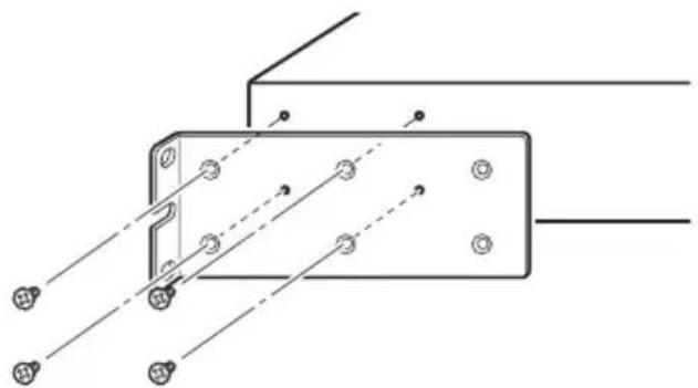
The rack mount hardware can be attached to this unit using either of the following two methods.
Method A: Attach the rack mount hardware so that its rack screw surface is flush with the front panel of this unit
natural_image
Technical diagram of a mechanical assembly with mounting holes and connecting rods (no text or labels)Method B: Install the unit 4 cm deeper than method A (recessed)
If the 19-inch rack cabinet has a door, use this method of attachment. Install the unit in a recessed position so that cables inserted in the front panel of the unit do not contact the door of the rack.
natural_image
Technical line drawing of a mechanical bracket with mounting holes and connecting wires (no text or symbols)Installation on a wall or ceiling
SWR2310-18GT / SWR2310-10G
Use the separately sold WK-SWR wall mount accessory to install the unit.
If attaching this unit to a ceiling, invert the top and bottom of the unit.
You will need to obtain six screws that fit the holes described in step 1 and are appropriate for the material and thickness of the wall or ceiling.
Carry out the installation completely, all the way to step 7.
Here we explain using mainly the SWR2310-10G as an example.

natural_image
Technical line drawings of two electronic device modules (no text or symbols)SWR2310-18GT SWR2310-10G

Caution
- Do not attach this unit to a wall or ceiling that is higher than 2 meters.
If the unit falls, injury or damage might occur.
- When attaching or removing this unit, you must disconnect the unit's power plug from the power outlet.
Failing to do so could cause electrical shock or malfunctions.
• Installation must be performed by a qualified installer. During installation, pay attention to the following points.
- Choose hardware and a location that is well able to support the weight of this unit
- Avoid locations that are subject to sustained vibration
- You must use the specified installation accessory
• Perform periodic maintenance checks
Notice
- The mounting accessory has a surface to which the SWR2310-18GT/SWR2310-10G must be attached and a surface that must be attached to the wall or ceiling. If these two surfaces are confused, it will not be possible to attach the mounting accessory to the SWR2310-18GT/SWR2310-10G. To distinguish the surfaces, refer to the illustrations for step 1 and step 3.
-
The position of the unit relative to the mounting accessory differs by 90 degrees between the SWR2310-18GT and the SWR2310-10G.
-
Place the mounting accessory against the wall or ceiling, and mark the installation location.

text_image
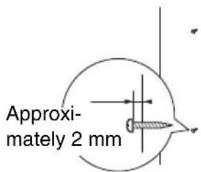
SWR2310-18GT/SWR2310-10G Attachment surface (not stamped) Mark the wall Wall installation surface (stamped) 2-R2.5 ø10 2-ø5.5 WK-SWR- Provisionally attach four commercially available screws to the locations that you marked in step 1.
At this time, leave approximately 2 mm between the head of the screw and the surface of the wall or ceiling, allowing room for the mounting accessory to engage the screws (illustration at right).
text_image
Approximately 2 mm
Warning
You must use screws that are appropriate for the material of the wall or ceiling. If the unit falls, injury or damage might occur.
- Align the unit with the mounting accessory (illustration below).
Notice
If the supplied feet have already been attached to the unit, remove them.
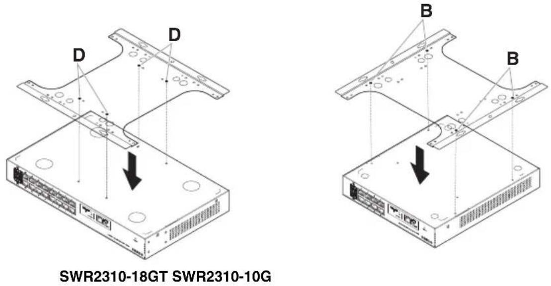
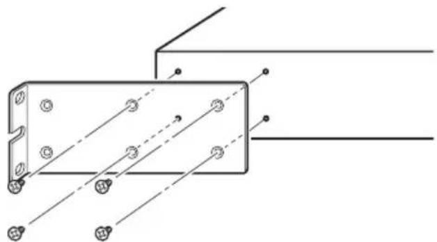
text_image
SWR2310-18GT SWR2310-10G- Using four screws included with the mounting accessory, attach it to the SWR2310-18G/SWR2310-10G.
Fasten it securely.

Warning
- Use only the specified screws that were included.
If the unit falls, injury or damage might occur. This could also cause electric shock or malfunctions.
• Take care when letting your hand or finger contact the corners of the mounting accessory.
Inattention might cause injury.

text_image
A B B C D D A B C D DNotice
The screw holes to use are stamped with a “D” (SWR2310-18GT) or “B” (SWR2310-10G) on the mounting accessory.
The screws to use are the small black M3 × 4 screws for the metal chassis.
- Engage the assembled mounting accessory onto the commercially available screws that you provisionally attached in step 2, and slide it to the side.

Warning
Do not drop the unit.
If the unit falls, injury or damage might occur.
Notice
When installing the unit sideways, engage the mounting accessory onto the commercially available screws, and slide it either to the left or the right.
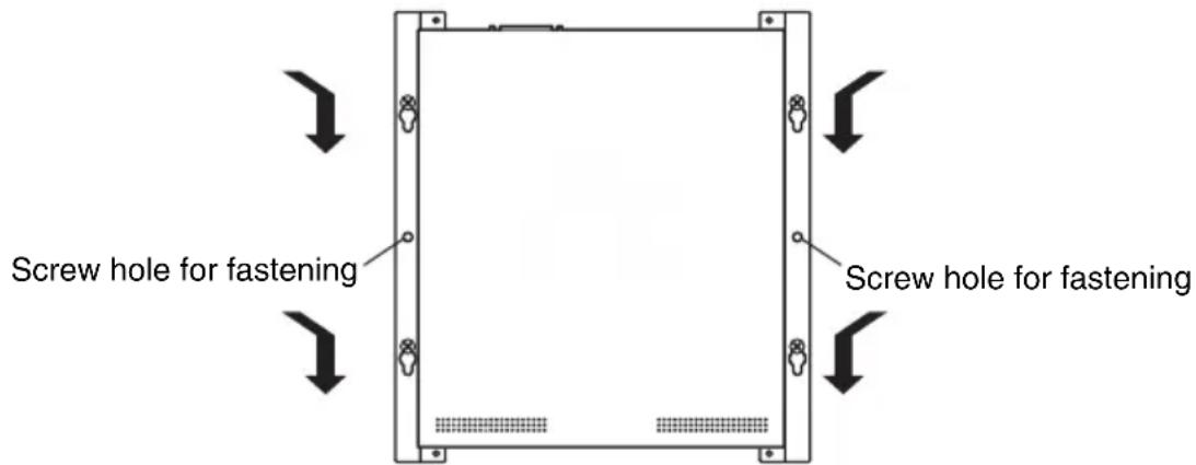
text_image
Screw hole for fastening Screw hole for fastening- Further tighten the commercially available screws that you provisionally attached in step 2, fastening the mounting accessory.
- Install two commercially available screws in the fastening screw holes (two locations) of the mounting accessory.

Warning
You must use screws that are appropriate for the material of the wall or ceiling. If the unit falls, injury or damage might occur.
Settings for this unit can be made in the following ways.
- Make settings using the Web GUI
- Make settings from the command line using the CONSOLE port
- Make settings from the command line using Telnet
- Make settings from the command line using SSH
This document explains "Make settings using the Web GUI" (page 27) and "Making settings from the command line using the CONSOLE port" (page 28).
You can log in to this unit either as a standard user or as an administrative user. This document explains how to log in as an administrative user.
For details on the commands used by this unit, refer to the command reference.
The command reference is available on the Yamaha website.
http://www.yamaha.com/proaudio/
Make settings using the Web GUI
Here we explain the procedure for logging in to this unit using the Web GUI.
You will use Yamaha LAN Monitor to log in to the Web GUI, so install Yamaha LAN Monitor before you continue.
Before you log in, connect your computer to the same network.
For details on supported web browsers, refer to the Yamaha website.
http://www.yamaha.com/proaudio/
■ Logging in to this unit using a web browser
- Start Yamaha LAN Monitor.
- Select the device for which you want to make settings, and click the Web GUI button in the "Device Details" view.
When access is successful, a dialog box appears where you can enter a user name and password. - If you are making settings ahead of time, enter the user name and password, and click the "log in" button.
With the factory settings, the user name and password are not specified, so it is not necessary to enter a user name and password.
Making settings from the command line using the CONSOLE port
Here we explain the cable, driver, software, and settings that are necessary in order to use the CONSOLE port.
■ Preparing a console cable
- Connect the computer to the CONSOLE port of this unit using a USB cable or an RJ-45/DB-9 console cable.
- As the USB cable connected to the mini-USB CONSOLE port, use a USB cable that is equipped with a USB Type A connector and a USB mini-B (5-pin) connector, and that supports data communication. Charge-only cables cannot be used.
■ Installing the USB serial driver
- In order to use the mini-USB CONSOLE port, the USB serial driver must first be installed in the computer.
- For details on installing the USB serial driver, refer to the “Yamaha Network Device USB Serial Driver Installation Guide.”
The Yamaha Network Device USB Serial Driver Installation Guide and the installer can be downloaded from the Yamaha website.
http://www.yamaha.com/proaudio/
■ Preparing the computer
You will need terminal software that controls the serial (COM) port of the computer. Set the parameters of the terminal software as follows.
| Parameter Value | |
| Data transmission speed 9600 bps | |
| Character bit length 8 | |
| Parity check None | |
| Number of stop bits 1 | |
| Flow control Xon/Xoff |
If the computer is connected to both the RJ-45 CONSOLE port and the mini-USB CONSOLE port, only the terminal software that uses the mini-USB CONSOLE port can make settings.
The messages that are output from this unit are output to both CONSOLE ports.
■ Logging in from a computer connected to the CONSOLE port
1. Using a console cable, connect this unit to the computer.
Connect the computer to the CONSOLE port of this unit using a USB cable or an RJ-45/DB-9 console cable.
Notice
- The LAN ports and the RJ-45 CONSOLE port all use the same 8-pin connector. If you connect these wrongly, hardware damage or malfunction might occur.
Take care when making connections.
- If you use the mini-USB CONSOLE port, do not use a USB hub. If multiple Yamaha switches are connected to one computer, the COM port numbers assigned to the connection might be inadvertently exchanged. Take care that you are not changing the settings of an unintended unit.
2. Check the power supply of this unit.
If this unit is not powered-on, turn on the power as described in “Turning the power on” (page 33). When this unit powers-on and the command line is usable, a startup message appears in the console screen of the computer.
If the power is already on, a startup message does not appear.
SWR2310 Rev.2.04.01 (Mon Sep 4 16:28:06 2018)
Copyright (c) 2020 Yamaha Corporation. All Rights Reserved.
3. Press the key.
The system waits for a user name to be entered.
If a user name has already been specified, enter the user name.
When the unit is shipped from the factory, a user name has not been specified, so it need not be entered.
Username:
4. Press the key.
The system waits for a password to be entered.
If a password has already been specified, enter the password.
When the unit is shipped from the factory, a password has not been specified, so it need not be entered.
Password:
5. Press the key.
If password authentication is successful, the command prompt appears, allowing you to enter commands.
For details on the commands, refer to the command reference.
SWR2310>
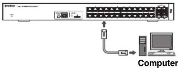
■ Connecting to a network device or a computer
Notice
Do not connect this product to public Wi-Fi and/or Internet directly.
Only connect this product to the Internet through a router with strong password-protections.
Consult your router manufacturer for information on security best practices.
flowchart
graph TD
    A["Server"] --> B["Switch"]
    B --> C["Computer"]
    D["Data Bus"] --> B
    E["Computer"] --> B
Using LAN cables, connect the LAN port of the network device or computer to the LAN ports of this unit. If using fiber optic cables to make connections, install an appropriate SFP module or SFP+ module in an SFP/SFP+ port.
For the installation procedure, refer to "Installing an SFP module" (page 30).

Caution
The LAN ports and the RJ-45 CONSOLE port all use the same 8-pin connector. If you connect these wrongly, hardware damage or malfunction might occur. Take care when making connections.
■ Installing an SFP module
- SFP ports ( ):SWR2310-10G SFP module (SFP-SWRG-SX,SFP-SWRG-LX)
- SFP + pc SWR2310-28GT SWR2310-18GT SFP+ module (SFP-SWRT-SR, SFP-SWRT-LR), SFP module (SFP-SWRG-SX, SFP-SWRG-LX)
Supported SFP modules and SFP+ modules are collectively referred to here as SFP modules.
- Remove the dust cover that is affixed to this unit's SFP/SFP+ port, and insert the SFP module.
Memo
Since this unit supports hot-swapping, an SFP module can be installed without turning the power off.
- Remove the protective cap from the SFP module.

Caution
SFP/SFP+ port
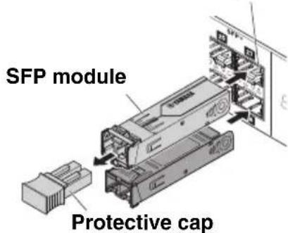
text_image
SFP module Protective capDo not look into the optical emitter when the SFP module is installed.
The SFP modules separately sold by Yamaha are class 1 laser devices. They may emit laser beams invisible to the eye. If the laser beam enters your eye, your eyesight might be damaged.
- To the connector, connect a fiber optic cable that is suitable for each module.
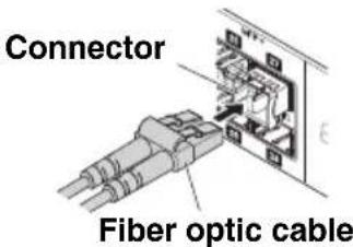
text_image
Connector Fiber optic cable■ Removing an SFP module
Secure this unit so that it will not move, and while grasping the lever of the SFP module, pull it slowly toward yourself to remove the module from the SFP/SFP+ port. Supported SFP modules and SFP+ modules are collectively referred to here as SFP modules.
- Detach the fiber optic cable.

text_image
Connector Fiber optic cable- If the SFP module is connected to the upper row of ports, lower the SFP module's lever.
If it is connected to the lower row of ports, raise the lever.
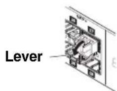
text_image
Lever
Caution
Do not look into the optical emitter when the SFP module is installed.
The SFP modules separately sold by Yamaha are class 1 laser devices. They may emit laser beams invisible to the eye. If the laser beam enters your eye, your eyesight might be damaged.
- Grasp the lever and pull out the SFP module.
Memo
Since this unit supports hot-swapping, an SFP module can be removed without turning the power off.
Connections
■ Installing a direct attach cable SWR2310-28GT / SWR2310-18GT
A direct attach cable (DAC-SWRT-3M, DAC-SWRT-1M) can be installed in an SFP+ port of the SWR2310-28GT or SWR2310-18GT.
- Remove the protective cap from the SFP+ module section of the direct attach cable, and remove the dust cover from the SFP+ port of this unit.
- Grasp the SFP+ module section of the direct attach cable, insert it firmly into the SFP+ port of this unit, and engage the lock.
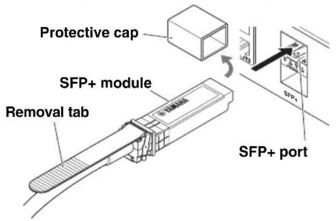
text_image
Protective cap SFP+ module Removal tab SFP+ SFP+ port
text_image
Locked Unlocked■ Removing a direct attach cable SWR2310-28GT / SWR2310-18GT
- While using one hand to push the SFP+ module section inward, use the other hand to pull the removal tab toward yourself, disengaging the lock.
- When the lock disengages, continue pulling the removal tab and slowly pull out the SFP+ module section.
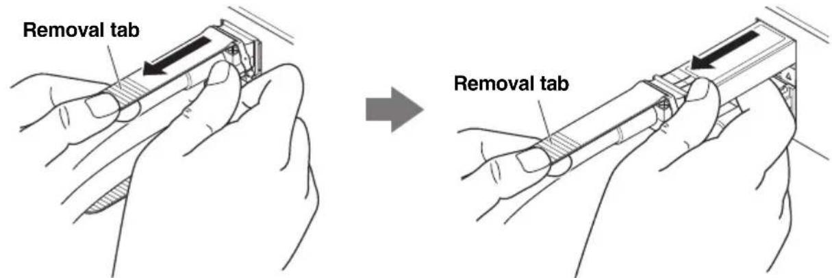
text_image
Removal tab Removal tab
Caution
- Do not grasp the cable of the direct attach cable when disconnecting it. Doing so might cause malfunctions.
- Do not disconnect the cable by pulling only the removal tab. Doing so might cause malfunctions.
- First verify that the lock is disengaged, and then disconnect the cable. Forcibly disconnecting the cable will damage the direct attach cable or cause this unit to malfunction.
■ Making stack connections SWR2310-28GT
Attach a direct attach cable or an SFP+ module (SFP-SWRT-SR or SFP-SWRT-LR) to an SFP+ port of the SWR2310-28GT. If using an SFP+ module, you must additionally provide a fiber optic cable that is suitable for the SFP+ module.
For details on installing or removing a direct attach cable, refer to "Installing a direct attach cable" SWR2310-28GT and SWR2310-18GT and "Installing a direct attach cable"
SWR2310-28GT / SWR2310-18GT (page 32).
For the procedure of installing an SFP+ module, refer to "Installing an SFP module" (page 30).
For details on stack connections, refer to the SWR2310 series "Technical Reference."
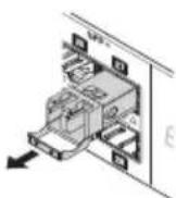
■ Turning the power on
1. Attach the included power cord clamp.
To prevent accidental disconnection of the power cord, insert the included power cord clamp ("included clamp" in the illustration at right) into the power cord clamp holes of the unit ("holes in the unit" in the illustration at right) and secure the power cord.
- The included power cord clamp is only for the included power supply cord.
- If you use the clamp for other power cords, they might be damaged or might not secure properly.

text_image
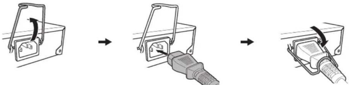
Insert the included clamp into the holes of the unit.2. Connect the included power cord to the power inlet, and secure it with the clamp.
flowchart
graph LR
    A["Device with switch"] --> B["Switch with plug"]
    B --> C["Device with cable or plug"]
① Raise the clamp.
② Connect the power cord.
③ Press down on the clamp to secure the power cord.
3. Connect the power cord to an electrical outlet.
The POWER indicator flashes green, and after startup is completed, is lit green.

Caution
If the POWER indicator is lit orange, the temperature inside the unit is abnormal. Reconsider the environment in which this unit is installed, and correctly install this unit so that its internal temperature is appropriate.
4. Check the port indicators.
If the left indicator (LINK/ACT) of ports connected to a network device or a computer is lit green or flashing green, the status is normal.
[If the left indicator of the port (LINK/ACT) is not lit green or flashing green]
Check whether the cable is correctly connected to the port, and whether the connected network device or computer is powered-on.
For details on the connection status, refer to "Port indicators" (page 19).
This unit can be restored to its factory-set state in the following ways.
- Using the Web GUI to restore the factory settings (page 34)
- Using the cold start command to restore the factory settings (page 35)
- Entering the [I] (uppercase I) key during startup to restore the factory settings (page 35)
Notice
When restoring the factory settings, note the following points.
- All communication is halted immediately after execution.
- When you execute this, the settings will also return to their factory-set state. If necessary, use external memory to save the settings before you proceed with initialization. For details on how to export settings to external memory, refer to the SWR2310 series “Technical Reference.”
■ Using the Web GUI to restore the factory settings
This unit can be restored to its factory-set state by making settings from the Web GUI. Log in to the Web GUI from Yamaha LAN Monitor.
- Choose "Administration" tab – "Maintenance" – "Restart or Initialize." The "Restart or Initialize" screen appears.
- In the "Initialize" section, click the "Proceed" button.
The "Initialize" screen appears.
- Enter the administrative password, and click "Confirm."
The "Confirm execution" screen appears.
- Verify the content, and click the "Execute" button.
The unit is returned to its factory-set state. Also, the “Initialization” dialog box appears, and the unit restarts.
- After this unit has finished restarting, access the Web GUI once again from Yamaha LAN Monitor.
NOTE
During restart, the computer on which the Web GUI is open will be unable to communicate with the unit (the status indication of the computer's network adapter will be "Network cable is not connected"), but the communication status will recover when restart is completed. After this unit's POWER indicator has finished flashing, verify that communication has been restored for the computer on which the Web GUI is open, and then click the Web GUI button in the "Device Details" view.
■ Using the cold start command to restore the factory settings
You can return the unit to its factory settings by using a command line setting via the CONSOLE port, Telnet, or an SSH client.
Here we assume that you are logged in as described in "Logging in from a computer connected to the CONSOLE port" (page 29).
1. Enter enable, and press the key.
You are now in privileged EXEC mode.
SWR2310>enable
SWR2310#
2. Enter the cold start command, and press the key.
You will be asked to enter the administrative password.
If a password has already been specified, enter the password.
When the unit is shipped from the factory, a password has not been specified, so it need not be entered.
SWR2310#cold start Password:
3. Press the key.
The unit returns to the factory-set state, and then restarts.
■ Entering the [I] (uppercase I) key during startup to restore the factory settings
The unit can be restored to its factory settings by entering an uppercase "I" when the unit is starting up. This explanation uses the method of disconnecting and reconnecting the power cord. The procedure is also the same when using the reload command to restart this unit.
Notice
Here we assume that you are logged in as described in “Logging in from a computer connected to the CONSOLE port” (page 29).
- Disconnect and then reconnect the power cord of this unit.
- After restart, enter an uppercase "I" within one second after the BootROM Ver (see below) appears on the console screen.
SWR2310 BootROM Ver.1.00
Memo
Before the BootROM Ver appears on the console screen, you can press the [Caps Lock] key or hold down the [Shift] key so that you will be ready to enter an uppercase "I" immediately.
3. When a screen asks you whether to execute initialization, press the key to execute initialization.
Initialize or not ?(y/n)
Initialization is executed.
Ready to Initialize
Hardware specifications
| Item | SWR2310-28GT | SWR2310-18GT | SWR2310-10G | |
| Dimensions(W x D x H units: mm)not including protrusions and feet | 440 mm(W) x300 mm(D) x44.0 mm(H) | 330 mm(W) x200 mm(D) x43.5 mm(H) | 220 mm(W) x250 mm(D) x40.5 mm(H) | |
| Weight (without included items) | 3.9 kg 2.1 kg 1.7 kg | |||
| Power supply voltage and frequency | AC100 – 240V, 50/60 Hz | |||
| Maximum power consumption | 25.2 W 19.0 W | 11.7 W | ||
| CONSOLE port | Standard RS-232C, USB 2.0 | |||
| Connector | RJ-45, USB mini-B (5-pin) | |||
| Data transmission speed | 9600 bit/s | |||
| LAN ports | Standard | IEEE802.3 (10BASE-T/100BASE-TX/1000BASE-T) | ||
| Number of ports | 24 | 16 | 8 | |
| Communication mode | Auto negotiation | |||
| Connector | RJ-45 | |||
| Polarity | Automatic detection of straight/cross, or fixed at straight | |||
| SFP+ ports | Standard | IEEE802.3z (1000BASE-SX/ 1000BASE-LX), IEEE802.3ae (10GBASE-SR/ 10GBASE-LR) | – | |
| Number of ports | 4 | 2 | – | |
| SFP ports | Standard | – | IEEE802.3z(1000BASE-SX/1000BASE-LX) | |
| Number of ports | – | 2 | ||
| microSD slot | Standard microSD/microSDHC (microSDXC is not supported) | |||
| File System | FAT/FAT32 | |||
| Indicators | POWER, microSD, STACK ID, LAN port (LINK/ACT, SPEED), SFP+ port (LINK/ACT, SPEED) | POWER, microSD, LAN port (LINK/ACT, SPEED), SFP+ port (LINK/ACT, SPEED) | POWER, microSD, LAN port (LINK/ACT, SPEED), SFP port (LINK/ACT, SPEED) | |
| MAC address Indicated in product label on top panel of unit | ||||
| Operating environment conditions | Ambient temperature | 0–50 °C | ||
| Ambient humidity | 15–80% (non-condensing) | |||
| Storage environment conditions | Ambient temperature | -20–60 °C | ||
| Ambient humidity | 10–90% (non-condensing) | |||
| Included items | Owner's manual (this document), power cord (3-prong), power cord clamp, legs | |||
| 19-inch rack mount hardware and screws – | ||||
The explanations in this document use the current specifications as of the date of publication. The latest version can be downloaded from the Yamaha website. http://www.yamaha.com/proaudio/
Dimensional diagram
SWR2310-28GT

text_image
2.3 300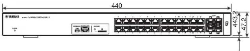
text_image
440 443.2 47.2Units: mm
SWR2310-18GT

text_image
2.3 200
text_image
330 43.53 2 46.7Units: mm
SWR2310-10G

text_image
2.3 250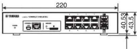
text_image
220 40.53 43.5Units: mm
RJ-45/DB-9 console cable pin configuration
Console (RS-232C)
| Signal | RJ-45 D-SUB 9 | |
| 9 | ||
| RTS | 1 | 8 |
| DTR | 2 | 6 |
| TxD | 3 | 2 |
| GND | 4 | 5 |
| GND | 5 | |
| RxD | 6 | 3 |
| DSR* | 7 | 7 |
| CTS* | 8 | 4 |
| 1 | ||
* DSR and CTS signals are not used by the SWR2310 series.
The model number, serial number, power requirements, etc., may be found on or near the name plate, which is at the top of the unit. You should note this serial number in the space provided below and retain this manual as a permanent record of your purchase to aid identification in the event of theft.
Model No.
Serial No.
(top_en_01)
Software license agreement
This License Agreement (the “AGREEMENT”) is a legal agreement between you and Yamaha Corporation (“YAMAHA”) under which YAMAHA is providing the firmware of YAMAHA’s network products (the “PRODUCT”) and related software program, documentation and electronic files (collectively, the “SOFTWARE”).
YAMAHA grants you a personal non-exclusive license to use the SOFTWARE only for purposes of running it on the PRODUCT.
This AGREEMENT applies to the SOFTWARE which YAMAHA provides you and the installed copy thereof, subject to the provision of 1-1 herein, into the PRODUCT or personal computer owned by you.
1. GRANT OF LICENSE:
1-1. YAMAHA grants you a personal non-exclusive license to install the SOFTWARE and use the SOFTWARE on the PRODUCT or other devices, including but not limited to the personal computer, which you own.
1-2. You shall not assign, sublicense, sell, rent, lease, loan, convey or otherwise transfer to any third party, upload to a website or a server computer to which specified or unspecified persons may access, or copy, duplicate, translate or convert to another programming language the SOFTWARE except as expressly provided herein. You shall not alter, modify, disassemble, decompile or otherwise reverse engineer the SOFTWARE and you also shall not have any third party to do so.
1-3. You shall not modify, remove or delete a copyright notice of YAMAHA contained in the SOFTWARE.
1-4. Except as expressly provided herein, no license or right, express or implied, is hereby conveyed or granted by YAMAHA to you for any intellectual property of YAMAHA.
2. OWNERSHIP AND COPYRIGHT:
The SOFTWARE is protected under the copyright laws and owned by YAMAHA. You agree and acknowledge that YAMAHA transfers neither ownership interest nor intellectual property in the SOFTWARE to you under this AGREEMENT or otherwise.
3. EXPORT RESTRICTIONS:
You agree to comply with all applicable export control laws and regulations of the country involved, and not to export or re-export, directly or indirectly, the SOFTWARE in violation of any such laws and regulations.
4. SUPPORT AND UPDATE:
YAMAHA, YAMAHA's subsidiaries and affiliates, their distributors and dealers are not responsible for maintaining or helping you to use the SOFTWARE. No updates, bug-fixes or support will be made available to you for the SOFTWARE.
5. DISCLAIMER OF WARRANTY:
5-1. THE SOFTWARE IS PROVIDED "AS IS" WITHOUT WARRANTY OF ANY KIND, EITHER EXPRESS OR IMPLIED, INCLUDING, BUT NOT LIMITED TO THE IMPLIED WARRANTIES OF MERCHANTABILITY AND FITNESS FOR A PARTICULAR PURPOSE.
5-2. IN NO EVENT SHALL YAMAHA, YAMAHA'S SUBSIDIARIES AND AFFILIATES, THEIR DISTRIBUTORS AND DEALERS BE LIABLE FOR ANY DAMAGES WHATSOEVER (INCLUDING WITHOUT LIMITATION, LOSS OF BUSINESS PROFITS, LOSS OF BUSINESS INFORMATION, LOSS OF BUSINESS INTERRUPTION OR OTHER INCIDENTAL OR CONSEQUENTIAL DAMAGES) ARISING OUT OF THE SOFTWARE, USE THEREOF, OR INABILITY TO USE THEREOF EVEN IF YAMAHA, YAMAHA'S SUBSIDIARIES AND AFFILIATES, THEIR DISTRIBUTORS OR DEALERS HAVE BEEN ADVISED OF THE POSSIBILITY OF SUCH DAMAGES. SOME STATES DO NOT ALLOW THE LIMITATION OR EXCLUSION OF LIABILITY FOR INCIDENTAL OR
CONSEQUENTIAL DAMAGES, SO THE ABOVE LIMITATION OR EXCLUSION MAY NOT APPLY TO YOU. SOME STATES DO NOT ALLOW THE LIMITATION OR EXCLUSION OF LIABILITY FOR INCIDENTAL OR CONSEQUENTIAL DAMAGES, SO THE ABOVE LIMITATION OR EXCLUSION MAY NOT APPLY TO YOU.
5-3. YAMAHA, YAMAHA'S SUBSIDIARIES AND AFFILIATES, THEIR DISTRIBUTORS AND DEALERS SHALL HAVE NO OBLIGATION TO INDEMNIFY YOU AGAINST ANY CLAIM OR SUIT BROUGHT BY A THIRD PARTY ALLEGING THAT THE SOFTWARE OR USE THEREOF INFRINGES ANY INTELLECTUAL PROPERTY OF SUCH THIRD PARTY.
6. TERM:
6-1. This AGREEMENT becomes effective upon your agreeing to the terms and conditions herein and continues in effect unless or until terminated in accordance with the provision of 6-2 or 6-3 herein.
6-2. You may terminate this AGREEMENT by deleting the SOFTWARE installed into the PRODUCT.
6-3. This AGREEMENT will also terminate if you fail to comply with any of the terms and conditions of this AGREEMENT.
6-4. In case this AGREEMENT is terminated in accordance with the provision 6-3, you shall promptly delete the SOFTWARE.
6-5. Notwithstanding anything contains herein, Sections 2 through 6 shall survive any termination or expiration hereof.
7. SEPARABILITY:
In the event that any provision of this AGREEMENT is declared or found to be illegal by any court or tribunal of competent jurisdiction, such provision shall be null and void with respect to the jurisdiction of that court or tribunal and all the remaining provisions of this AGREEMENT shall remain in full force and effect.
8. U.S. GOVERNMENT RESTRICTED RIGHTS NOTICE:
The Software is a “commercial item,” as that term is defined at 48 C.F.R. 2.101 (Oct 1995), consisting of “commercial computer software” and “commercial computer software documentation,” as such terms are used in 48 C.F.R. 12.212 (Sept 1995). Consistent with 48 C.F.R. 12.212 and 48 C.F.R. 227.7202-1 through 227.72024 (June 1995), all U.S. Government End Users shall acquire the Software with only those rights set forth herein.
9. ACKNOWLEDGMENT:
You agree that this AGREEMENT is the complete and exclusive statement of agreement between you and YAMAHA concerning the subject matter hereof and supersedes all proposals or prior agreements, verbal or written, and any other communications between you and the parties relating to the subject matter hereof. NO amendment to this AGREEMENT shall be effective unless signed by a duly authorized representative of YAMAHA.
10. GOVERNING LAW:
This AGREEMENT shall be governed by and construed in accordance with the laws of Japan without reference to the principles of conflict of laws.
C
Cold start command.... 35
Command line.... 28
CONSOLE port 28
Cooling vents 18
D
Direct attach cable 32
|
Initialization 34
L
LAN ports.... 13
Leg....20
Leg attachment guides.... 15
M
microSD indicator.... 13
microSD slot.... 13
mini-USB CONSOLE port 13, 28
P
Password 27
Power cord clamp 33
Power cord clamp attachment holes..... 16
POWER indicator.... 12
Power supply inlet.... 16
Product label 18
R
Rack mount accessory
attachment holes.... 15, 18
RJ-45 CONSOLE port.... 13
RK-SWR 20
S
SFP ports 13
SFP+ module 30
SFP+ ports 13
Stack connections 33
Stack ID indicator 13
U
User name.... 27
W
Wall mount accessory attachment holes... 15
Web GUI 27
WK-SWR.... 24
Y
Yamaha LAN Monitor.... 11, 27
Yamaha network device
USB serial driver 11,28
产品中有害物质的名称及含量
natural_image
Symbol of no smoking or fire, featuring a crossed-out smoke trail inside a circle (no text or numbers present)仅适用于非热带气候条件下安全使用。
a1 = 22 - a2
Important Notice: Guarantee Information for customers in European Economic Area (EEA) and Switzerland
| Important Notice: Guarantee Information for customers in EEA* and SwitzerlandFor detailed guarantee information about this Yamaha product, and Pan-EEA* und Switzerland warranty service, please either visit the website address below (Printable file is available at our website) or contact the Yamaha representative office for your country. * EEA: European Economic Area | English |
| Wichtiger Hinweis: Garantie-Information für Kunden in der EWR* und der SchweizFür nähere Garantie-Information über dieses Produkt von Yamaha, sowie über den Pan-EWR*- und Schweizer Garantieservice, besuchen Sie bitte entweder die folgend angegebene Internetadresse (eine druckfähige Version befindet sich auch auf unserer Websielle), oder wenden Sie sich an den für Ihr Land zuständigen Yamaha-Vertrieb. * EWR: Europäischer Wirtschaftsraum | Deutsch |
| Remarque importante: Informations de garantie pour les clients de l'EEE et la SuissePour des informations plus détaillées sur la garantie de ce produit Yamaha et sur le service de garantie applicable dans l'ensemble de l'EEE ainsi qu'en Suisse, consultez notre site Web à l'adresse ci-dessous (le fichier imprimable est disponible sur notre site Web) ou contactez directement Yamaha dans votre pays de résidence. * EEE: Espace Economique Européen | Français |
| Belangrijke mededeling: Garantie-informatie voor klanten in de EER* en ZwitserlandVoor gedetailleerde garantie-informatie over dit Yamaha-product en de garantieservice in heel de EER* en Zwitserland, gaat u naar de onderstaande website (u vind een afdrukbaar bestand op onze website) of neemt u contact op met de vertegenwoordiging van Yamaha in uw land. * EER: Europese Economische Ruimte | Nederlands |
| Aviso importante: información sobre la garantia para los clientes del EEE* y SuizaPara una información detallada sobre este producto Yamaha y sobre el soporte de garantía en la zona EEE* y Suiza, visite la dirección web que se incluye más abajo (la version del archivo para imprimir esta disponible en nuestro sitio web) o póngase en contacto con el representante de Yamaha en su país. * EEE: Espacio Económico Europeo | Español |
| Avviso importante: Informazioni sulla garanzia per i clienti residenti nell'EEA* e in SvizzeraPer informazioni dettagliate sulla garanzia relativa a questo prodotto Yamaha e l'assistenza in garanzia nei paesi EEA* e in Svizzera, potete consultare il sito Web all'indinizzo riportato di seguito (à disponibile il file in formato stampable) oppure contattare l'ufficio di rappresentanza locale della Yamaha. * EEA: Area Economica Europea | Italiano |
| Aviso importante: informações sobre as garantias para clientes da AEE* e da SuíçaPara obter uma informação pormenorizada sobre este produto da Yamaha e sobre o serviço de garantia na AEE* e na Suíça, visite o site a seguir (o arquivo para impressão está disponível no nosso site) ou entre em contato com o escritório de representação da Yamaha no seu país. * AEE: Área Econômica Européia | Português |
| ΕλληνικάΓια λεπτομερείς πληροφορίες εγγύησης σχητικά με το πορόν προϊόν της Yamaha και την κόλυψη εγγύησης σε όλες τις χώρες του ΕΟΧ και την Ελβετία, επισκερτείε την πορακάτω ιστοσελίδα (Εκτυπώστωη μορεή) ελναι διαθέσωη την κτοσελίδα μας) ή απευδυνθείτε στην αντιπροσωπεία της Yamaha στη χώρα σας. * ΕΟΧ: Ευρωπαϊκός Οικονομικός Χιώρος | Svenska |
| Viktigt: Garantinformation kör kunder i EES-området* och SchweizFör detaljerad information om denna Yamahaprodukt samt garantiservice i hela EES-området* och Schweiz kan du antingen besöka nedanstående webbaddress (en utskriftsvänlig fil finns på webbplatsen) eller kontakta Yamahas officiella representant i ditt land. * EES: Europeiska Ekonomiska Samarbetsområdet | Norsk |
| Viktig merknad: Garantiinformasjon for kunder i E∅S* og SveitsDetafert garantiinformasjon om dette Yamaha-produktet og garantiservice for hele E∅S-området* og Sveits kan fås enten ved å besøke nettadressen nedenfor (utskriftsvensjon finnes på våre nettsider) eller kontakte kontakte Yamaha-kontoret i landet der du bor. *EOS: Det europeiske ekonomiske samarbeidsområdet | Dansk |
| Vigtig oplysning: Garantioplysninger til kunder i E∅O* og SchweizDe kan finde detajerede garantioplysninger om dette Yamaha-produktet og den fælles garantiserviceordning for E∅O* (og Schweiz) ved at besøge det websted, der er angivet nedenfor (der findes en fil, som kan udskrives, på vores websted), eller ved at kontakte Yamahas nationale repræsentationskontor i det land, hvor De bor. * E∅O: Det Europæiske Ókonomiske Område | Suomi |
| Tärkeå Ilmoitus: Takuutiedot Euroopan talousalueen (ETA)* ja Sveitsin asiakkailleTämän Yamaha-tuetteen sekå ETA-alueen ja Sveitsin takuuta koskevat yksiltylskohtaiset tiedot saattie alla olevasta nettiosoitteesta. (Tulostettava tiedosto saatavissa sivustollamme.) Voitte myös ottaa yhteyttä paikalliseen Yamaha-edustajaan. *ETA: Euroopan talousalue | Polski |
| Wažne: Warunki gwarancyjne obowiązujące w EOG* i SzwajcariiAby dowiedzieć się więcej na temat warunków gwarancyjnych tego produktu firmy Yamaha i serwisu gwarancyjnego w całym EOG* i Szwajcarii, należy odwiedzić wskazaną porizej stronę internetową (Plik gotowy do wydkru znajduje się na naszej stronie internetowej) lub kontaktować się z przedstawicielstwem firmy Yamaha w swoim kraju. * EOG — Europejski Obszar Gospodarczy | Česky |
| Düležité oznámeni: Záruční informace pro zákazníky v EHS* a ve ŠvýcarskuPodrobné záruční informace o tomto produktu Yamaha a záručním servisu v celém EHS* a ve Švýcarsku naleznete na niže uvedené webové adrese (soubor k tisku je dostupný na našich webových stránkách) nebo se můžete obrátit na zastoupení firmy Yamaha ve své zemi. * EHS: Evropsky hospodářský prostor | Magyar |
| Fontos figyelmeztefés: Garancia-informaciók az EGT* területén és Svájcban élő vásárlók számáraA jelen Yamaha termékre vonatkozó részletes garancia-informaciók, valamint az EGT*-re és Švájcra kiterjedő garanciális szolgáltatás tekintetében keresse fel webhelyünket az alábbi cimen (a webhelyen nyomtatható fájtí is talál), vagy pedig lépjen kapcsolatba az országában működő Yamaha képviseleti irodával. * EGT: Európai Gazdasági Térseg | Eesti keel |
| Oluline márkus: Garantiiteave Euroopa Majanduspiirkonna (EMP)* ja Šveitsi klientideLa tapsema teabe saamiseks selte Yamaha toote garantii ning kogu Europa Majanduspiirkonna ja Šveitsi garantiiteeninduse kohta, kütastage patun veebisati alljárgneval aadressil (miele saidil on saadaval prinditav fail) või põörduge Tele regioni Yamaha esinduse poole. * EMP: Euroopa Majanduspiirkond | Latviešu |
| Svarigs pazipojums: garantijas informacija klientiem EEZ* un ŠveicėLai saņemtu detalžētu garantijas informaciju par šo Yamaha produktu, kā arī garantijas apkalpošanu EEZ* un Šveicė, lõdzu, apmekléjiet zemäk norădito ľimekja vietnes adresi (tîmekja vietne ir pieejams drukăjams fails) vai sazinieties ar jūsu valsti apkalpojošo Yamaha pärstávniecību. * EEZ: Europas Ekonomikas zona | Latviešu |
| Dèmesio: informacija dél garantijos pirkëjams EEE* ir ŠveicariijojeJei reikia išsamios informacijos apie šļ „Yamaha” produktą ir jo techninę priežliņra visoje EEE* ir Šveicarijoje, apsilankykite mūsų svetainėje toliau nurodytu adresu (svetainėje yra spausdintinas failas) arba kreipkitės į „Yamaha” atstovybę savo šalią. * EEE – Europos ekonominė erdvė | Lietuvlu kalba |
| Döležité upozornenie: Informacie o záruke pre zákazníkov v EHP* a ŠvajčiarskuPodrobné informacie o záruke týkajúce sa lohto produktu od spoločnosti Yamaha a garančnom servise v EHP* a Švajčiarsku nájdete na webovej stránke uvedenej nižäie (na našej webovej stránke je k dispozícii súbor na tlač) alebo sa obrätte na zástupcu spoločnosti Yamaha vo svojej krajine. * EHP: Európsky hospodářsky priestor | Slovenčina |
| Pomembno obvestlio: Informacije o garanciji za kupce v EGP* in ŠviciZa podrobnješie informacije o tem Yamahinem izdelku ter garancijskem servisu v celotnem EGP in Švici, obiščite spletno mesto, ki je navedeno spodaj (natisljiva datoteka je na voljo na našem spletnem mestu), ali se obrnite na Yamahinega predstavnika v svoji državi. * EGP: Evropski gospodarski prostor | Slovenčina |
| Bажно съобщение: Информация за гаранцията за клиенти в ЕИП* и ШвейцарияЗа подробна информация за гаранцията за този продукт на Yamaha и гаранционното обслужване в паневропейската зона на ЕИП* и Швейцария или посетете посочения по-долу уеб сайт (на нашия учеб сайт има файл за печат), или се свържете с представителния офис на Yamaha във вашата страна. * ЕИП: Европейско ikonomическо пространство | Български език |
| Notificare importante: Informații despre garantie pentru clienti din SEE* și ElvetiaPentru informații detaliate privind acest produs Yamaha și serviciul de garantie Pan-SEE* și Elvetia, vizilatți site-ul la adresa de mai jos (fișierul imprimabil este disponibil pe site-ul nostru) sau contactați biroul reprezentanței Yamaha din jara dumneavoastră. * SEE: Spațiul Economic European | Limba română |
| Važna obavijest: Informacije o jamstvu za države EGP-a ŠvicarskeZa detaljne informacije o jamstvu za ovaj Yamahin proizvod te jamstvenom servisu za cijeli EGP i Švicarsku, molimo Vas da posjetite web-stranicu navedenu u nastavku ili kontaktirate ovlaštenog Yamahinog dobavljača u svojoj zemlji. * EGP: Europski gospodarski prostor | Hrvatski |
https://europe.yamaha.com/warranty/
Information for users on collection and disposal of old equipment:

This symbol on the products, packaging, and/or accompanying documents means that used electrical and electronic products should not be mixed with general household waste.
For proper treatment, recovery and recycling of old products, please take them to applicable collection points, in accordance with your national legislation.
By disposing of these products correctly, you will help to save valuable resources and prevent any potential negative effects on human health and the environment which could otherwise arise from inappropriate waste handling.
For more information about collection and recycling of old products, please contact your local municipality, your waste disposal service or the point of sale where you purchased the items.
For business users in the European Union:
If you wish to discard electrical and electronic equipment, please contact your dealer or supplier for further information.
Information on Disposal in other Countries outside the European Union:
This symbol is only valid in the European Union. If you wish to discard these items, please contact your local authorities or dealer and ask for the correct method of disposal.
(weee_eu_en_02)
Yamaha Canada Music Ltd.
135 Milner Avenue, Toronto, Ontario,
M1S 3R1, Canada
Tel: +1-416-298-1311
U.S.A.
Yamaha Corporation of America
6600 Orangethorpe Avenue, Buena Park, CA 90620,
U.S.A.
Tel: +1-714-522-9011
CENTRAL & SOUTH AMERICA
MEXICO
PANAMA AND OTHER LATIN
AMERICAN COUNTRIES/
CARIBBEAN COUNTRIES
Yamaha Music Latin America, S.A.
Sherbourne Drive, Tilbrook, Milton Keynes,
MK7 8BL, U.K
Tel: +44-1908-366700
GERMANY
Yamaha Music Europe GmbH
Siemensstrasse 22-34, 25462 Rellingen, Germany
Tel: +49-4101-303-0
Switzerland in Thalwil
Seestrasse 18a, 8800 Thalwil, Switzerland
Tel: +41-44-3878080
AUSTRIA/BULGARIA/
CZECH REPUBLIC/HUNGARY/
ROMANIA/SLOVAKIA/SLOVENIA
Yamaha Music Europe GmbH
Branch Austria
Schlciergasse 20, 1100 Wien, Austria
Tel: +43-1-60203900
POLAND
Yamaha Music Europe GmbH
Valletta Road, Mosta MST9010, Malta
Tel: +356-2133-2093
NETHERLANDS/BELGIUM/
LUXEMBOURG
Yamaha Music Europe Branch Benelux
Clarissenhof 5b, 4133 AB Vianen, The Netherlands
Tel: +31-347-358040
FRANCE
Yamaha Music Europe
Yamaha Music Europe GmbH, Branch Italy
19th klm. Leof. Lavriou 190 02 Pcania – Attiki,
Greece
Tel: +30-210-6686168
SWEDEN/FINLAND/ICELAND
Yamaha Music Europe GmbH Germany filial
Scandinavia
JA Wettergrensgata 1, 400 43 Göteborg, Sweden
Tel: +46-31-89-34-00
DENMARK
Yamaha Music Denmark,
Fillial of Yamaha Music Europe GmbH, Tyskland
Generatorvej 8C, ST. TH., 2860 Søborg, Denmark
Tel: +45-44-92-49-00
NORWAY
Yamaha Music Europe GmbH Germany -
Norwegian Branch
Grini Næringspark 1. 1332 ∅sterås, Norway
Tel: +47-6716-7800
CYPRUS
Yamaha Music Europe GmbH
Siemensstrasse 22-34, 25462 Rellingen, Germany
Tel: +49-4101-303-0
RUSSIA
Yamaha Music (Russia) LLC.
Room 37, entrance 7, bld. 7, Kievskaya street.
Moscow, 121059, Russia
Tel: +7-495-626-5005
OTHER EUROPEAN COUNTRIES
Yamaha Music Europe GmbH
Siemensstrasse 22-34, 25462 Rellingen, Germany
Tel: +49-4101-3030
AFRICA
Yamaha Music Gulf FZE
JAFZA-16, Office 512, P.O.Box 17328,
Jebel Ali FZE, Dubai, UAE
Tel: +971-4-801-1500
MIDDLE EAST
TURKEY
Yamaha Music Europe GmbH
Bati Atasehir Istanbul, Turkey
Tel: +90-216-275-7960
OTHER COUNTRIES
Yamaha Music Gulf FZE
JAFZA-16, Office 512, P.O.Box 17328,
Jebel Ali FZE, Dubai, UAE
Tel: +971-4-801-1500
ASIA
THE PEOPLE'S REPUBLIC OF CHINA
Yamaha Music & Electronics (China) Co., Ltd.
2F, Yunhcdasha, 1818 Xinzha-lu, Jingan-qu,
Shanghai, China
Tel: +86-400-051-7700
INDIA
Yamaha Music India Private Limited
P-401, JMD Megapolis, Sector-48, Sohna Road,
Gurugram-122018, Haryana, India
Tel: +91-124-485-3300
INDONESIA
PT. Yamaha Musik Indonesia (Distributor)
Yamaha Music Center Bldg. Jalan Jend. Gatot
Subroto Kav. 4, Jakarta 12930, Indonesia
Tel: +62-21-520-2577
KOREA
Yamaha Music Korea Ltd.
11F, Prudential Tower, 298, Gangnam-dacro,
Gangnam-gu, Seoul, 06253, Korea
Tel: +82-2-3467-3300
MALAYSIA
Yamaha Music (Malaysia) Sdn. Bhd.
No.8, Jalan Pcrbandaran, Kelana Jaya, 47301
Petaling Jaya, Selangor, Malaysia
Tel: +60-3-78030900
SINGAPORE
Yamaha Music (Asia) Private Limited
Block 202 Hougang Street 21, #02-00.
Singapore 530202, Singapore
Tel: +65-6740-9200
TAIWAN
Yamaha Music & Electronics Taiwan Co., Ltd.
2F., No.1, Yuandong Rd., Banqiao Dist.,
New Taipei City 22063, Taiwan (R.O.C.)
3, 4, 15, 16th Fl., Siam Motors Building,
891/1 Rama 1 Road, Wangmai,
Pathumwan, Bangkok 10330, Thailand
Tel: +66-2215-2622
VIETNAM
Yamaha Music Vietnam Company Limited
15th Floor, Nam A Bank Tower, 201-203 Cach
Mang Thang Tam St., Ward 4, Dist.3,
Ho Chi Minh City, Vietnam
Tel: +84-8-3818-1122
OTHER ASIAN COUNTRIES
http://asia.yamaha.com/
OCEANIA
AUSTRALIA
Yamaha Music Australia Pty. Ltd.
Level 1, 80 Market Street, South Melbourne,
V1C 3205, Australia
Tel: +61-3-9693-5111
COUNTRIES AND TRUST
TERRITORIES IN PACIFIC OCEAN
http://asia.yamaha.com/
Yamaha Pro Audio global website https://www.yamaha.com/proaudio/Yamaha Downloads https://download.yamaha.com/
Manual Development Group
© 2020 Yamaha Corporation