Pick your language and provide your email: we'll send you a specifically translated version.
This manual is not available in your language
Product Type
Digital Video Recorder
Brand
Vitek
Model
VT-SRP916
Dimensions (W x D x H)
430 x 300 x 50 mm
Weight
3 kg
Power Supply
DC 12V, 2A
Video Inputs
4 BNC channels
Recording Resolution
1080p (1920x1080) per channel
Storage
1 x SATA HDD (up to 4TB, not included)
Main Functions
Real-time recording, motion detection, remote viewing, playback, backup via USB
Connectivity
Ethernet (RJ45), HDMI, VGA, USB 2.0
Maintenance
Wipe with dry cloth; avoid liquids
Safety
Use only supplied power adapter; do not cover vents
Spare Parts & Repairability
Hard drive is user replaceable; other repairs by qualified technician
General Information
Includes remote control, power adapter, and mounting screws
Frequently Asked Questions - VT-SRP916 Vitek
How many cameras can I connect to the VT-SRP916?
The VT-SRP916 supports up to 4 BNC cameras simultaneously.
What is the maximum hard drive capacity?
It supports a single SATA hard drive up to 4TB (not included).
Can I view the DVR remotely?
Yes, you can remotely access the DVR via Ethernet (LAN/Internet) using a dedicated app or web browser.
What video resolutions are supported?
Each channel can record at 1080p (1920x1080) resolution.
Does the DVR support motion detection?
Yes, it features motion detection that can trigger recording and alerts.
How do I back up recorded footage?
You can back up footage via the USB port using a flash drive or externally via network.
What connectors are available for video output?
It offers HDMI and VGA outputs for connecting a monitor.
Is the power adapter included?
Yes, the DC 12V power adapter is included in the box.
Can I use a PoE camera with this DVR?
No, this model requires BNC analog cameras; it does not support PoE.
What is the warranty period?
Vitek typically offers a 1-year limited warranty on this DVR.
User questions about VT-SRP916 Vitek
0 question about this device. Answer the ones you know or ask your own.
Ask a new question about this device
No questions yet. Be the first to ask one.
Download the instructions for your Digital Video Recorder in PDF format for free! Find your manual VT-SRP916 -
Vitek and take your electronic device back in hand. On this page are published all the documents necessary for the use of your device. VT-SRP916 by Vitek.
USER MANUAL VT-SRP916 Vitek
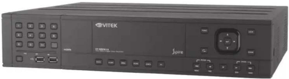
natural_image
Three stacked electronic devices labeled VITEK, VITEK Home, and VITEK SPIRE, each with ports and control buttons (no readable text beyond branding)
The VT-SR Series product is capable of receiving up to 16 channels of 960H camera inputs of video and audio and recording onto a hard disk drive in real-time, as well as providing monitoring, playback and backup footage in 960H resolution.
It also provides transferring video and audio data to the networked external devices, which allows remote monitoring environment for computers and mobile devices including cell phones.
The VT-SR Series manuals covers the following instructions:
95 To Move to the Search Menu while in Playback Mode
96 Search Settings
99 If you Want to Play
102 To start the Archive Menu
105 What is the Web Viewer?
107 Live Screen at a Glance
111 Search
113 Setup
129 SPIRE DVR Smartphone App
141 Getting Started with the Backup Player
143 Backup Player At a Glance
146 Compatible HDD Specifications
147 Troubleshooting (FAQ)
148 VITEK Limited Product Warranty
Introduction
Safety Instructions
Vitek shall not have any responsibility for any accident or damage that may incur during the use of the product. For your safety, we provide the following instructions regarding installation, cleaning, assembly/disassembly of the product. Please read carefully, and comply with the instructions.
Before installation
Comply with the following instructions to prevent fire, explosion, system failure or electrical shock.
Remove the power supply module before proceeding.
- Check the input voltage (AC100V-AC240V) to the power supply module before connecting it.
- Keep the product away from humidity.
- Ensure that all devices connected to the product are properly earth-grounded.
In operation mode
Comply with the following instructions to prevent fire, explosion, system failure or electric shock.
- If you need to open the cover, consult with an authorized Vitek service technician.
- Do not connect multiple devices to a single power outlet.
- Keep the product away from dust or combustible substances (ex: propane gas).
- Do not touch product with wet hands.
- Do not insert anything into the vent of the ventilation system.
Do not apply excessive force when unplugging the power cord.
Disassembly & Cleaning
When cleaning the surface, use a dry cloth.
- Do not wipe the product using water, paint thinner or organic solvents.
- Do not dismantle, repair or modify the product on your own.
During installation
To prevent an accident or physical injury, please comply with the following:
- Secure at least 6 inches of distance between cooling fan and wall for a proper ventilation.
Install the product on a flat surface.
- Keep product away from direct sunlight or excessive temperature.
While in use
- Do not apply force or shake product while using it.
What's included
natural_image
3D rendered image of a computer mouse (no text or symbols visible)
natural_image
Retro television remote with control panel and two batteries (no visible text or symbols)
natural_image
Black cable with two terminal connectors, no visible text or symbols
Mouse x1 Remote Control x1 & Batteries (AAA x2) Power Cable x1
natural_image
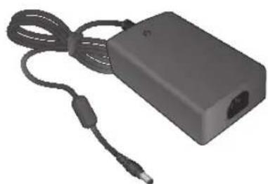
Black rectangular electronic device with cable and connector, no visible text or symbols
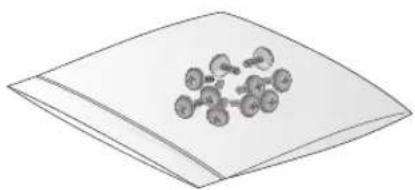
DC 12V Adaptor x1 Screws
natural_image
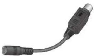
Close-up of a black cable with a connector, no visible text or symbols
Conversion adaptor (For 8-channel/16-channel)
chemical
Molecular structure diagram showing a central atom bonded to multiple surrounding atoms, likely representing a molecular model or cluster.
natural_image
Green VITEK USB flash drive with a circular logo, no visible text or symbols on the device itself.
User Manual on USB
natural_image
Simple line drawing of a stack of papers or documents (no text or symbols)
Quick Guide
SR-Series Remote
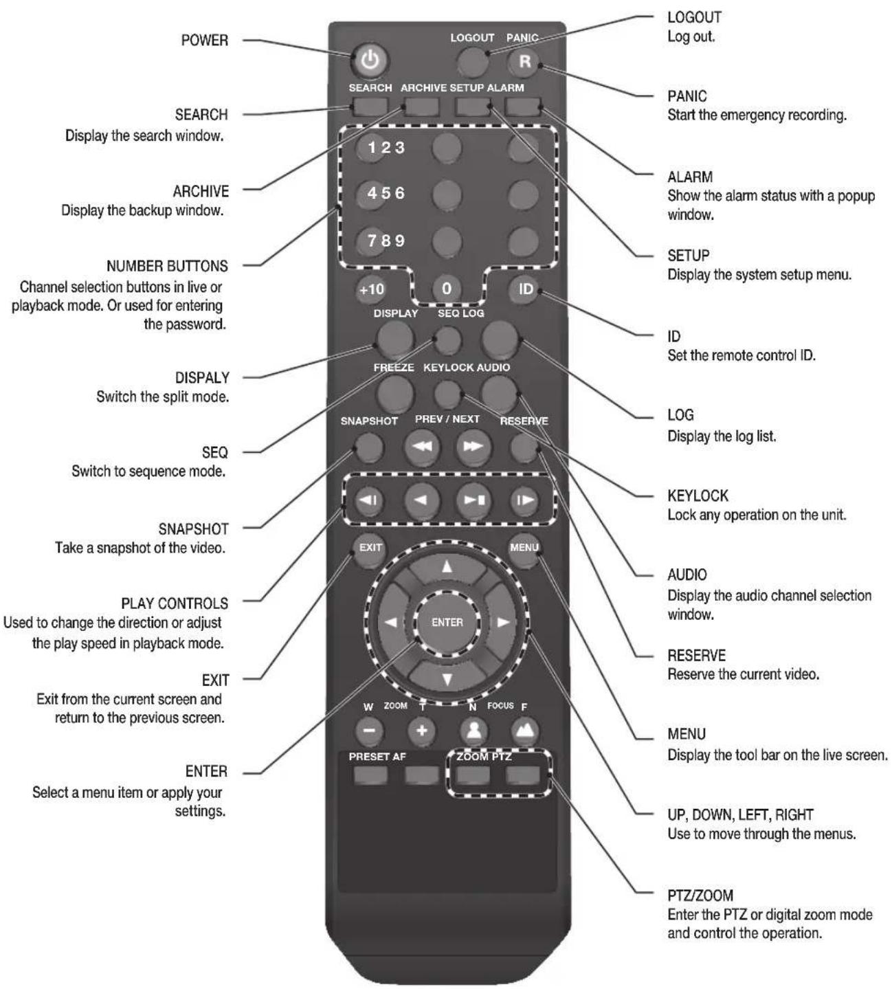
SR-SERIES Remote Control At a Glance
text_image
POWER
LOGOUT
PANIC
SEARCH
ARCHIVE SETUP ALARM
1 2 3
4 5 6
7 8 9
+10
0
ID
DISPLAY
SEO LOG
DOWNLOAD
Log out.
PANIC
Start the emergency recording.
ALARM
Show the alarm status with a popup window.
SETUP
Display the system setup menu.
ID
Set the remote control ID.
DISPALY
Switch the split mode.
SEQ
Switch to sequence mode.
SNAPSHOT
Take a snapshot of the video.
PLAY CONTROLS
Used to change the direction or adjust the play speed in playback mode.
EXIT
Exit from the current screen and return to the previous screen.
ENTER
Select a menu item or apply your settings.
KEYLOCK
Lock any operation on the unit.
AUDIO
Display the audio channel selection window.
RESERVE
Reserve the current video.
MENU
Display the tool bar on the live screen.
UP, DOWN, LEFT, RIGHT
Use to move through the menus.
PTZ/ZOOM
Enter the PTZ or digital zoom mode and control the operation.
Change the remote control ID
The remote control will only function if the Remote Control ID matches with that specified on the DVR.
If multiple DVRs are installed at one location and you would like to have just a single remote control, use the ID button to set the remote control ID. Only the ID-matching DVR can be controlled.
From
Press the [ID] button on the remote control. The default remote control ID is 00.
Use the number buttons to provide a two-digit ID. If you want to enter 01, for instance, enter the number 0 and 1 in sequence.
To check if the remote control ID is set properly, manipulate the remote control and see if the DVR responds.
To reset the ID to 00, press and hold the [ID] button.
VT-SRL Overview
natural_image
Two black VITEK Ethernet devices with ports and connectors, no visible text or symbols on the device bodies.
VT-SRL
4, 8 & 16 Channel 960H Digital Video Recorders
VT-SRL Key Features
This product is capable of receiving up to 16 channels of 960H camera inputs of video and audio and recording onto a hard disk drive in real-time, as well as providing monitoring, playback and backup footage in 960H resolution. It also provides transferring video and audio data to the networked external devices, which allows remote monitoring environment for computers and mobile devices including cell phones.
• Supports High Resolution 960H Cameras
• 4, 8 or 16 Video Inputs with 1 HDMI main monitor output, 1 VGA main monitor output, and 1 BNC Spot Out
• H.264 Compression
- Up to 480fps Live Display & 480fps Recording (VT-SRL916) / 240/240 (VT-SRL908) / 120/120 (VT-SRL904)
• Supports both Dynamic and Static IP Addresses
• Supports 2x internal Hard Drives (VT-SRL908/VT-SRL916) / 1x HDD (VT-SRL904)
- Remote Viewing over the Internet, with IE, Safari, Firefox, and Opera
• Applications for iPhone, iPad, iPod Touch and Android Devices
• Mac OSX Client & PC CMS Central Management Software Included
- Thumbnail Search
• Automatic sending of Health & Event notifications via email
• Control locally with the Included USB Mouse or IR Remote control
• PTZ Control over RS-485
• 4 Alarm Inputs / 1 Relay Out
VT-SRL- Specifications
Detailed Specifications
VT-SRL904
VT-SRL908
VT-SRL916
Video Input
4 Channels
8 Channels
16 Channels
Video Compression
H.264
H.264
H.264
FPS (Display / Recording)
120 / 120 (CIF, 2CIF, D1, 960H)
240 / 240 (CIF, 2CIF, D1, 960H)
480 / 480 (CIF, 2CIF, D1, 960H)
Playback Rate
120FPS @ 960H / 120FPS @ CIF
240FPS @ 960H / 240FPS @ CIF
480FPS @ 960H / 480FPS @ CIF
Operating System
Linux
Video Output
VGA / HDMI / Spot BNC
Spit-Screen
Live: 1, 4, SEQ, Playback: 1, 4
Live: 1,4,6,8,9, SEQ / Playback: 1, 4, 9
Live: 1, 4,6,8,9,16 SEQ / Playback: 1, 4,6,8,9,16
Audio In/Out
4 Line In (1/8") / 1 Line Out (1/8")
Alarm In/Out
4 Alarm Inputs / 1 Outputs with 1 Relay
Storage
1 Internal HDD (SATA)
2 Internal HDD (SATA)
2 Internal HDD (SATA)
Archive
USB Device & Network
USB Port
2 Front USB Ports
System Control
USB Mouse, Included IR Remote Control
Network
TCP/IP, HTTP, DHCP (DDNS)
RJ-45 Ethernet Port
10/100Mbps
10/100/1000Mbps
10/100/1000Mbps
Search
Thumbnail, Calendar, Event
PTZ
1 - RS-485
Recording Resolution Setting
By each camera for different resolution setting(CIF/2CIF/D1/960H)
Recording Quality Control
4 Levels (Low/Standard/High/Highest)
Recording Modes
Continuous, Schedule, Alarm, and Panic
Panic Record
Overrides all other recording settings to provide the best quality recording
Pre-recording
Max. 5 seconds
Post-recording
Max. 180 seconds
Motion Detection
Adjustable 20x12 Grid with 30 Steps Sensitivity Level
Player
Backup player, and HDD PC Viewer
E-mail notification
E-mails to specific users to notify events
System Configuration
Full setup configuration over network
Bandwidth limit
YES: Adjustable by User
Two-Way Audio
YES
Power
DC12V, Adaptor, 3.3A, 100~240V AC, 50-60Hz
Operating Temperature
32° ~ 104°F (0° ~ 40°C)
Humidity
10 ~ 90% NC
Case Form Factor
1.0U
Dimensions (W x H x D)
10" x 1.85" x 7.25"
12" x 1.85" x 12.25"
12" x 1.85" x 12.25"
Weight
3.3 lbs. (1.5kg)
6.85 lbs. (3.1kg)
6.85 lbs. (3.1kg)
VT-SRL Overview
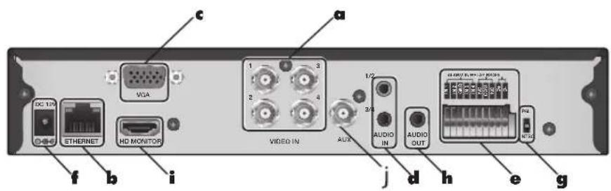
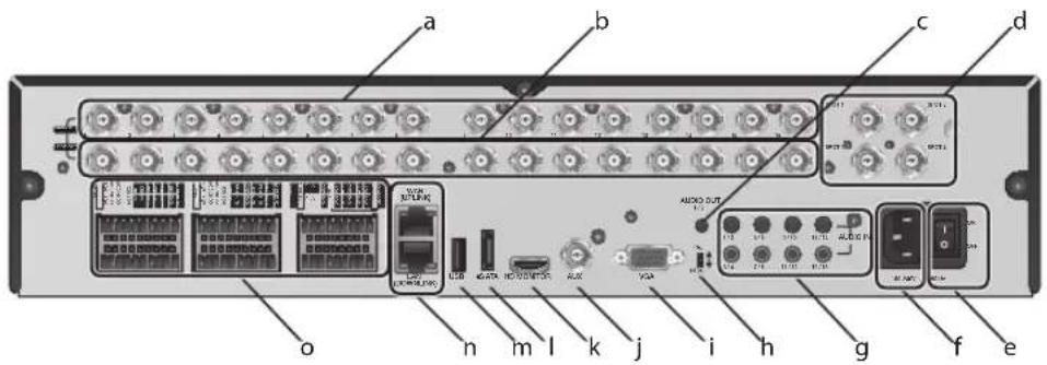
VT-SRL Rear Panel
4 channels
text_image
VGA
1 3
2 4
VIDEO IN
AUX
1/2
AUDIO IN
AUDIO OUT
CLDNOM ST. RPN-278
RPN
WDC
DC 12V
ETHERNET
HD MONITOR
f b i
j d h e g
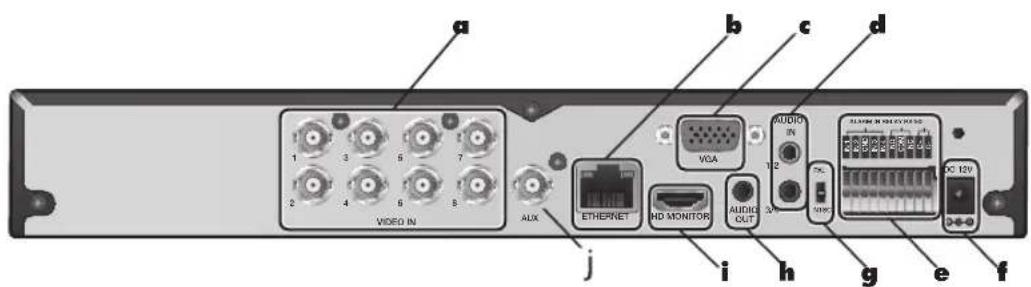
8 channels
text_image
a
1 3 5 7
2 4 6 8
VIDEO IN
AUX
b
c
d
VGA
AUDIO
1/2
i
j
HD MONITOR
AUDIO OUT
70%
ACI 12V
g
e
f
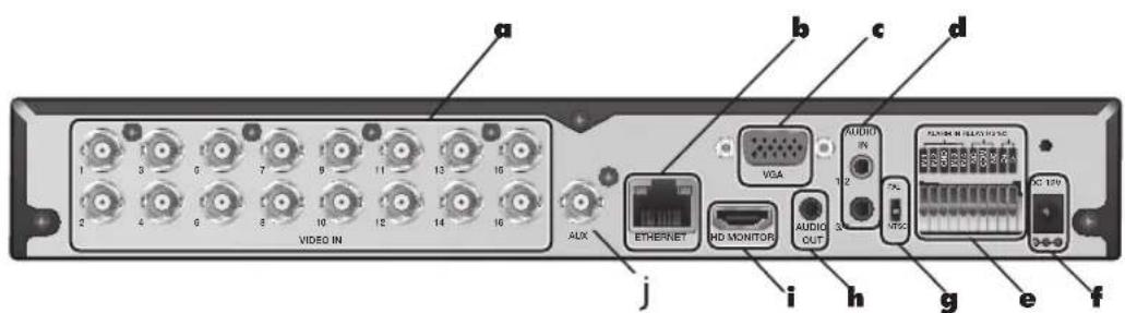
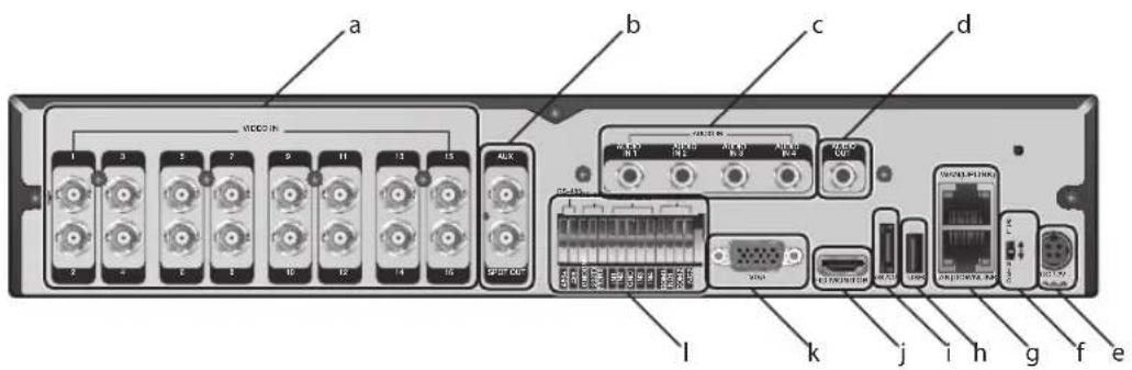
16 channels
text_image
a
1 3 6 7 9 11 13 15
2 4 6 8 10 12 14 16
VIDEO IN
b
c
d
VGA
AUDIO
IN
1/2
7k
MTSC
AC 12V
J
i
h
g
e
f
AUX
ETHERNET
MD MONITOR
AUDIO OUT
No.
Name
Description
a
VIDEO IN Video input terminal for cameras.
b
ETHERNET Network port for connection to the Internet, router or hub.
c
VGA VGA monitor video output port.
d
AUDIO IN 1/2: Audio input terminal that supports channels 1 and 2.
3/4: Audio input terminal that supports channels 3 and 4.
e
ALARM IN Alarm input signal port.
REL AY Relay Terminal output port.
RS485 Ports for communication with external devices such as PTZ camera and system keyboard.
f
DC 12V Power input port. Connect to a 12V adaptor.
g
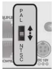
DIP Switch Select a video type (NTSC or PAL)
h
AUDIO OUT Port for speaker connection.
i
HD MONITOR HD monitor video output port.
j
AUX BNC Spot out
VT-SRL Installation
Replacing HDD
When a hard drive is full or problematic, it is possible to replace it yourself.
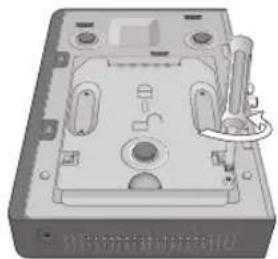
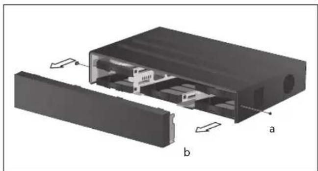
4-Channel Model
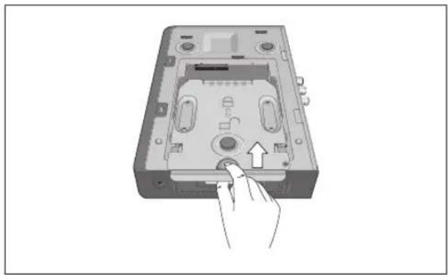
Remove the screw from the bracket on the bottom of the DVR.
natural_image
3D rendering of a mechanical housing or enclosure with internal components and mounting holes (no visible text or symbols)
Hold the HDD bracket with your finger as shown in the figure and pull it to separate it from the DVR.
natural_image
Hand inserting a button into a device casing (no text or symbols visible)
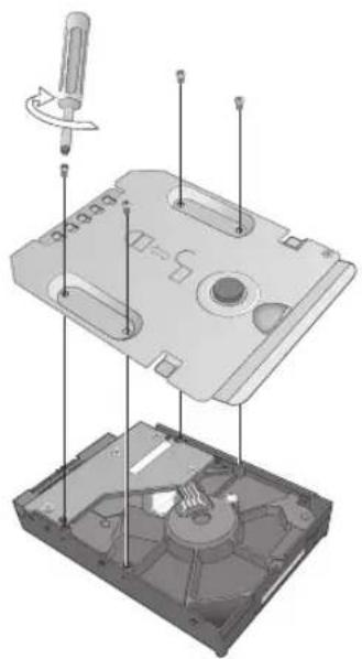
Install the HDD to the bracket (see figure).
When installing the HDD, make sure to install in the correct direction.
natural_image
Exploded view diagram of a mechanical device showing internal components and a screwdriver (no text or labels)
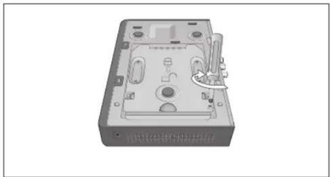
Insert the bracket back into the DVR.
natural_image
Hand inserting a CD into a device casing (no text or symbols visible)
Secure the bracket by fastening the screw.
natural_image
3D rendering of a mechanical device casing with internal components and a curved arrow indicating a component (no text or symbols visible)
VT-SRL Installation
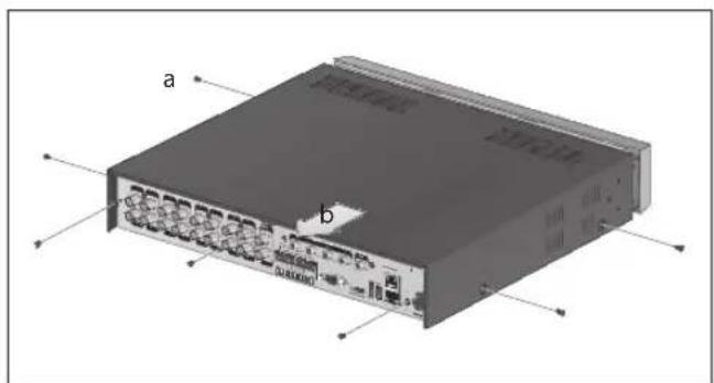
8/16-Channel Models
Remove the screw from each bracket on the bottom of the DVR.
natural_image
3D rendering of a mechanical housing with internal compartments and mounting holes (no text or symbols visible)
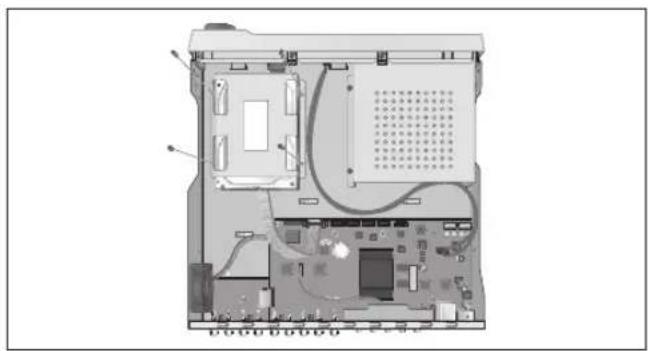
Hold the HDD bracket with your finger as shown in the figure and pull it to separate it from the DVR.
natural_image
Illustration of a computer case with a hand pointing to a button (no text or symbols visible)
Install the HDD to the bracket (see figure)
When installing the HDD, make sure to install in the correct direction.
natural_image
Exploded view diagram of a computer internal components (no text or symbols)
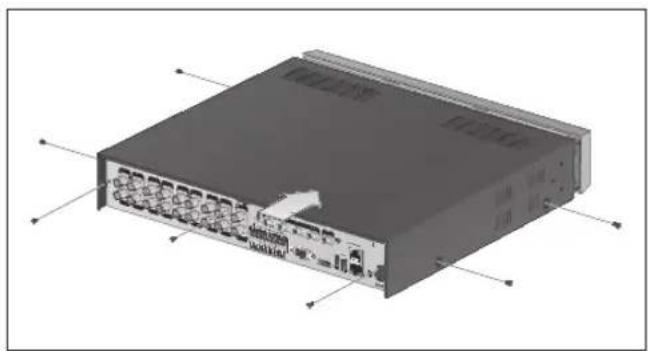
Insert the bracket back into the DVR.
natural_image
Diagram of a device casing with internal compartments and a hand pointing to a button (no text or symbols visible)
Secure the bracket by fastening the screw.
natural_image
3D rendering of a mechanical housing with internal compartments and mounting holes (no text or symbols visible)
VT-SRL Installation
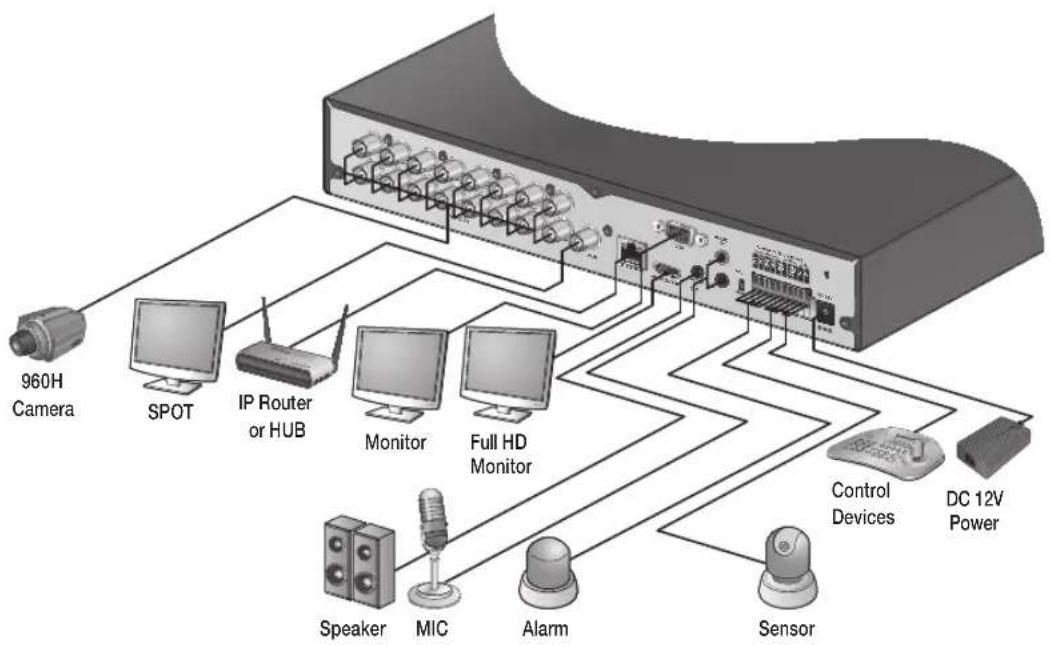
Basic Layout
flowchart
graph TD
    A["960H Camera"] --> B["SPOT"]
    B --> C["IP Router or HUB"]
    C --> D["Monitor"]
    C --> E["Full HD Monitor"]
    D --> F["Control Devices"]
    E --> G["DC 12V Power"]
    F --> H["Sensor"]
    G --> H
    I["Speaker"] --> J["MIC"]
    K["Alarm"] --> L["Sensor"]
- Cable quality and distance can directly effect the video quality. it is recommended to consult an authorized installer when installing the DVR.
Connecting to an external device
Connecting to a Monitor
This product supports 1080p 60 Hz HDMI monitors and regular monitors that support DVI and VGA inputs. Connect an HDMI cable to the port on the product's rear bottom, or connect an HDMI-DVI converter cable to connect a DVI monitor. Or, use VGA cable to connect the product with a VGA monitor.
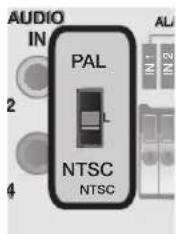
- Once the product is set for NTSC or PAL output, connect cameras of the corresponding video standard for proper operations.
Setting the product to NTSC or PAL decides available display output modes too.
The monitor's displaying operates at 50Hz if the product has been set to PAL output and the connected monitor supports both 50Hz and 60 Hz inputs. For NTSC setting, it works at 60 Hz.
- Make sure to connect the product to a monitor that supports 1920x1080 at 60Hz. (HDMI, DVI, VGA)
text_image
AUDIO
IN
PAL
NTSC
NTSC
Power Connection
Plug the provided DC 12V adaptor in the rear power port of the DVR.
For stable operation of the product, it is recommended to use the provided adapter. (12V, 5A)
● Make connection when the power is not applied yet.
Arrange the cables and be careful not to peel off the cable coating.
Do not place the power cord under the carpet or rug. The power cord is usually earth-grounded. However, even if it's not earth-grounded, do not modify it on your own for earth-grounding.
Do not plug multiple devices into single power outlet.
For stability, this product provides two separate adaptors and two corresponding AC cords by factory default. Make sure all cables are connected properly.
text_image
VIDEO IN
AUDIO
ETERNET
HD MONITOR
AUDIO OUT
AUDIO IN
VISA
100
DC 12V
ACATIN R-DELAY 7045
DC 12V adaptor
VT-SRL Installation
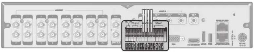
Alarm I/O Connection
text_image
1
2
3
4
5
6
7
8
9
10
11
12
13
14
15
16
VIDEO IN
AUDIO
IN
MGA
1/2
ETHERNET
HD MONITOR
AUDIO OUT
3/4
ALARM IN DELAY R0486.
N 1
N 2
EWB
N 3
N 4
N2
COM
NC
D1
DC EM
To connect the alarm input signal
Connect the signal line of an alarm input device to the rear [ALARM IN] port.
Push the Alarm In and [GND] terminals' top side (orange color) with a sharp tipped tool such as screw driver.
While pushing, insert one end of alarm signal cable into the hole of Alarm In terminal.
While pushing, insert one end of ground cable into the hole of [GND] terminal.
Check to be sure the cable has been inserted properly-- stop pushing and gently pull the cable to make sure it is secure. To disconnect a cable, push the top side of the terminal (orange color) and pull out the cable.
To connect the alarm output signal
Connect the signal cable of the alarm output device to the [RELAY] terminal on the product's rear side.
Push the [NO]/[NC]/[COM] terminal's top side (orange color) with a sharp tipped tool such as screw driver.
While pushing, insert one end of alarm signal cable into the desired terminal of [NO] or [NC].
NO(Normal Open) : Normally Open but switches to Closed if an alarm out occurs.
COM : Insert the grounding wire.
NC(Normal Closed): Normally Closed but switches to Open if an alarm out occurs.
Insert the ground signal wire into the hole of the [COM] port.
Check to be sure the cable has been inserted properly-- stop pushing and gently pull the cable to make sure it is secure. To disconnect a cable, push the top side of the terminal (orange color) and pull out the cable.
Communication Port
text_image
1
2
3
4
5
6
7
8
9
10
11
12
13
14
15
16
17
18
19
20
VIDEO IN
AUDIO
ETHERNET
HD MONITOR
AUDIO OUT
MGA
1/22
AUDIO IN
ALARM IN/DELAY/R4485
R1 1
R2 2
GND 3
N0 4
ND 5
DC 6
DC 7
DC 8
DC 9
DC 10
DC 11
DC 12
DC 13
DC 14
DC 15
DC 16
DC 17
DC 18
DC 19
DC 20
RS-485 Connection
Connect a PTZ Camera or Keyboard Controller.
After connecting the control device, be sure to match the connection settings between the DVR and the device.
To change communication settings see
Connect the positive (+) transmission signal cable of the PTZ camera/keyboard controller to the RS-485 [D+] communication port on the DVR's rear panel.
Connect the negative (-) transmission signal cable of the PTZ camera/keyboard controller to the RS-485 [D-] communication port on the DVR's rear panel.
For RS-485 communication configuration, refer to the user's manual of the applicable PTZ camera or keyboard controller.
Audio Device Connection
Connect an audio input device such as a microphone to the rear Audio In port; connect an audio output device such as an amplified speaker to the Audio Out port.
Storage and Mouse Connection
USB Device
You can connect and use USB storage devices for backup of recorded video, saving snapshots, firmware updating, importing/exporting user configurations. In addition, the DVR will accept a USB mouse.
- If you need to connect a USB HDD with a high power consumption, it is recommended to use a separate power source for that HDD.
20GB file size limit for backups
VT-SRL Installation
Network Connection
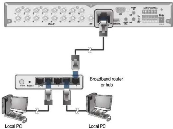
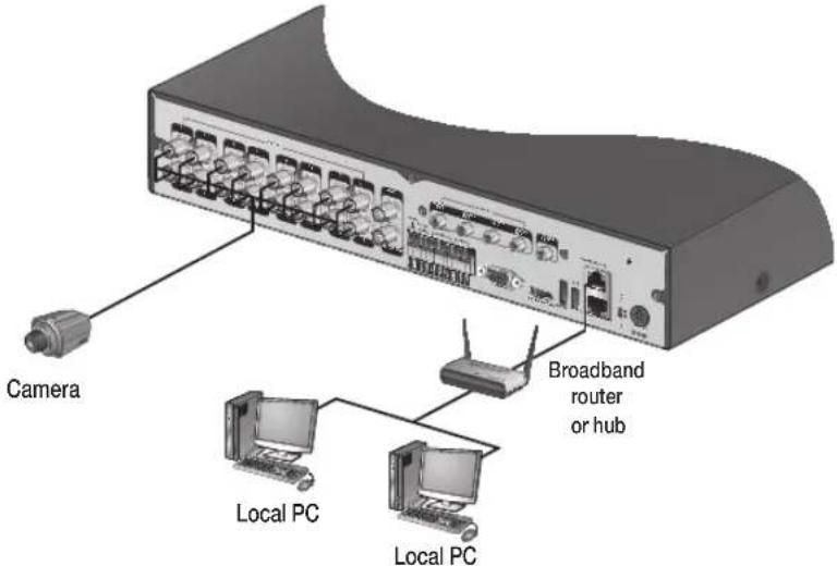
PC Connection - Local Network
You can connect the DVR to a PC in the same local area network.
text_image
Camera
Local PC
Local PC
Broadband router
or hub
Connect a CAT-5 network cable to the DVR's [ETHERNET] port on the rear panel to a router or hub.
Connect a local PC to the same router or hub.
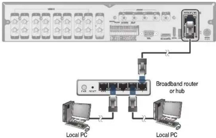
text_image
Broadband router
or hub
Local PC
Local PC
Enter the DVR's IP address in the Web browser in the format of: "http://IP address:Web service port" (Ex : http://192.168.0.23:8080) The web service port is set to 8080 by default. From the Network Setup screen, you can change the port number.
If using the dedicated PC S/W, refer to the user manual of the program.
Enter the DVR's Username and Password to log in. Factory default: ADMIN / 1234.
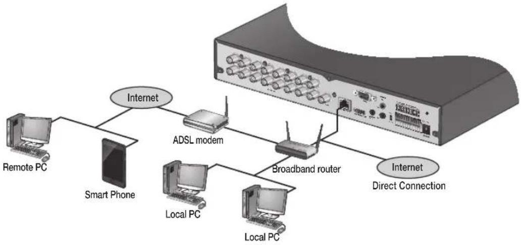
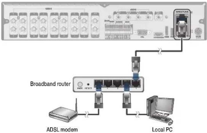
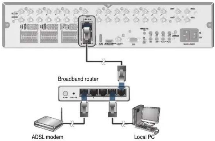
PC Connection - Remote Network
You can connect to the DVR from a remote PC or mobile device.
Connect a CAT-5 network cable to the DVR's [ETHERNET] port on the rear panel to a router or hub.
flowchart
graph TD
    A["Server"] -->|Internet| B["Smart Phone"]
    B --> C["Remote PC"]
    B --> D["Local PC"]
    B --> E["Local PC"]
    B --> F["ADSL modem"]
    F --> G["Broadband router"]
    G --> H["Internet Direct Connection"]
    G --> I["Internet"]
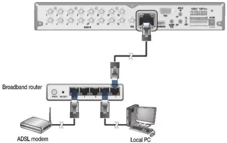
Connect the [WAN(UPLINK)] port of the router directly to the fixed IP LAN cable, or connect it to the ADSL modem.
flowchart
graph TD
    A["ADSL modem"] --> B["Switch"]
    B --> C["Router"]
    C --> D["Local PC"]
    D --> E["Switch"]
    E --> F["Switch"]
    F --> G["Switch"]
    G --> H["Switch"]
    H --> I["Switch"]
    I --> J["Switch"]
    J --> K["Switch"]
    K --> L["Switch"]
    L --> M["Switch"]
    M --> N["Switch"]
    N --> O["Switch"]
    O --> P["Switch"]
    P --> Q["Switch"]
    Q --> R["Switch"]
    R --> S["Switch"]
    S --> T["Switch"]
    T --> U["Switch"]
    U --> V["Switch"]
    V --> W["Switch"]
    W --> X["Switch"]
    X --> Y["Switch"]
    Y --> Z["Switch"]
    Z --> AA["Switch"]
    AA --> AB["Switch"]
    AB --> AC["Switch"]
    AC --> AD["Switch"]
    AD --> AE["Switch"]
    AE --> AF["Switch"]
    AF --> AG["Switch"]
    AG --> AH["Switch"]
    AH --> AI["Switch"]
    AI --> AJ["Switch"]
    AJ --> AK["Switch"]
    AK --> AL["Switch"]
    AL --> AM["Switch"]
    AM --> AN["Switch"]
    AN --> AO["Switch"]
    AO --> AP["Switch"]
    AP --> AQ["Switch"]
    AQ --> AR["Switch"]
    AR --> AS["Switch"]
    AS --> AT["Switch"]
    AT --> AU["Switch"]
    AU --> AV["Switch"]
    AV --> AW["Switch"]
    AW --> AX["Switch"]
    AX --> AY["Switch"]
If using a router, make sure BOTH the Web Service Port and RTSP Port have been port forwarded.
You can remotely access your DVR in the following ways:
a. The DVR's MAC address
b. The DVR's DDNS Host Name aka DVR NAME
c. The external IP address of the network
NOTE: See page 74 for more detail
VT-SRE Overview
text_image
VITEK
VT-025914
VITEK Internet Explorer
Spire
HDMI
VT-SRE
4, 8 & 16 Channel 960H Digital Video Recorders
VT-SRE Key Features
This product is capable of receiving inputs from up to 16 channels of 960H camera inputs of video and audio and recording onto a hard disk drive in real-time, as well as providing monitoring, playback and backup footages in excellent quality of 960H resolution.
It also provides transferring video and audio data to the networked external devices, which allows remote monitoring environment for computers and mobile devices including cell phones.
Up to 16 channels of 960H camera video can be displayed at 480 fps / 400 fps in real time
Up to 16 channels of 960H camera videos can be saved at maximum 480 (NTSC) / 400 (PAL) fps.
Simultaneous recording and playback of maximum 16 channels (at 120 fps @ 960H)
• Supports H.264 HP (High Profile) CODEC
Auto alarm feature with self-diagnostics on the system (HDD S.M.A.R.T, system temperature, network error, FAN error, etc.)
• Supports dual streaming for remote access service
• Supports HDD extension (eSATA)
Various search methods (time, event, bookmark and thumbnail)
• Mass storage backup via USB port or FTP server
• Supports remote access and search using web browser
• Dedicated smart phone applications that can be used with iPhone and iPad or on Android OS
• 1080p Full HD GUI
VT-SRE- Specifications
Detailed Specifications
VT-SRE904
VT-SRE908
VT-SRE916
Video Input
4 Channels
8 Channels
16 Channels
Video Compression
H.264
H.264
H.264
FPS (Display / Recording)
120 / 120 (CIF, 2CIF, D1, 960H)
240 / 240 (CIF, 2CIF, D1, 960H)
480 / 480 (CIF, 2CIF, D1, 960H)
Playback Rate
120FPS @ 960H / 120FPS @ CIF
240FPS @ 960H / 240FPS @ CIF
480FPS @ 960H / 480FPS @ CIF
Operating System
Linux
Video Output
VGA / HDMI
Spit-Screen
Live: 1, 4, SEQ / Playback: 1, 4
Live: 1,4,6,8,9, SEQ / Playback: 1, 4, 9
Live: 1, 4,6,8,9,16 SEQ / Playback: 1, 4,6,8,9,16
Audio In/Out
4 Line In (RCA) / 1 Line Out (RCA)
Alarm In/Out
4 Alarm Inputs / 2 Outputs with 1 Relay
Storage
2 Internal HDD (SATA)
4 Internal HDD (SATA)
4 Internal HDD (SATA)
Archive
USB Device & Network
USB Port
3 Ports (2 Front + 1 Rear)
eSATA
N/A
YES
YES
System Control
Front Panel, USB Mouse, Included IR Remote Control
Network
TCP/IP, HTTP, DHCP (DDNS)
RJ-45 Ethernet Port
1 - 10/100/1000Mbps
1 (LAN) + 1 (WAN) - 10/100/1000Mbps
1 (LAN) + 1 (WAN) - 10/100/1000Mbps
Search
Calendar, Event
PTZ
1 - RS-485
Recording Resolution Setting
By each camera for different resolution setting(CIF/2CIF/D1/960H)
Recording Quality Control
4 Levels (Low/Standard/High/Highest)
Recording Modes
By hour, by day, by recording mode, By alarm, By Ch
Panic Record
Overrides all other recording settings to provide the best quality recording
Pre-recording
Max. 5 seconds
Post-recording
Max. 180 seconds
Motion Detection
Adjustable 20x12 Grid with 10 Steps Sensitivity Level
Player
Backup player, and HDD PC Viewer
E-mail notification
E-mails to specific users to notify events
System Configuration
Full setup configuration over network
Bandwidth limit
YES: Adjustable by User
Two-Way Audio
YES
Power
12V Adaptor, 6.67A, 100~220VAC, 50~60Hz
Operating Temperature
32° ~ 104°F (0° ~ 40°C)
Humidity
10 ~ 90% NC
Case Form Factor
1.5U
Dimensions (W x H x D)
14.5" x 14.5" x 2.75"
Weight
8.0 lbs (3.6kg)
VT-SRE Overview
VT-SRE Rear Panel
text_image
a
b
c
f
VCCD H
CH3 CH3
VCCD OUT
AHX
AUDIO R
CH3 CH3
CH2 CH3
AUDIO
SUT
HD MCANTOS
VGA
USB
ST-DCOUT
DC-120
WAN(UPLINK) Network port for connection to the Internet, router or hub
LAN(DOWN LINK) Port for connecting the dedicated network device. (Do not share it with other device)
h
USB Used for connecting USB storage or mouse
i
eSATA Connection port for external eSATA storage
j
HD-MONITOR HD monitor video output port
k
VGA VGA monitor video output port
l
ALARM IN Alarm input signal port
RELAY 1/2 Relay Terminal output port
RS485 Ports for communication with external devices such as PTZ camera and system keyboard
RS232 Connection ports for signal cables to external devices such as PTZ camera, POS and ATM devices
VT-SRE Installation
Replacing HDD
When an HDD is full or problematic, it is possible to replace it yourself.
If installed 2 HDD drives
Below illustrations are based on the 16-channel model.
Remove screws on the DVR's rear and sides.
Pull the cover case forward to separate it.
natural_image
3D diagram of a network switch device with labeled ports (a and b), showing internal components without any text or symbols beyond labels.
Remove screws on the hard drive bracket to separate it from the main unit.
natural_image
Interior view of a computer desktop showing CPU socket, drive bays, and circuit board (no text or labels visible)
Once the bracket is separated, remove screws on both sides of the HDD drive to be separated and replaced.
Install the new HDD and fix screws on both sides.
When installing the HDD, make sure to install in the correct direction.
natural_image
3D mechanical assembly diagram showing layered components with mounting holes and mounting points (no text or symbols)
Carefully align the bracket to the main unit and firmly tighten screws on both sides.
natural_image
Top-down schematic of a computer motherboard showing CPU socket, drive bays, and circuit board (no text or labels)
Connect the data cable to the HDD and main unit.
natural_image
Interior view of a computer case showing internal components and a close-up of the front panel (no text or symbols visible)
Put the cover back on the unit and tighten screws on its rear and both sides.
natural_image
3D rendering of a server rack unit with ports and connectors (no visible text or labels)
VT-SRE Installation
Basic Layout
Cable quality and distance can directly effect the video quality. it is recommended to consult an authorized installer when installing the DVR.
flowchart
graph TD
    A["960H Camera"] --> B["Monitor"]
    A --> C["SPOT Monitor"]
    A --> D["Control Devices"]
    D --> E["Alarm"]
    D --> F["Sensor"]
    D --> G["MIC"]
    E --> H["Full HD (RGB) Monitor"]
    F --> I["Speaker"]
    G --> J["SPOT Monitor"]
    H --> K["sSATA Storage"]
    I --> K
    J --> K
    K --> L["Mouse"]
    L --> M["IP Router or HUB"]
    M --> N["DC 12V Power"]
Connecting to an external device
Connecting to the monitor
This product supports 1080p 60 Hz HDMI monitors and regular monitors that support DVI and VGA inputs. Connect an HDMI cable to the port on the product's rear bottom, or connect an HDMI-DVI converter cable to connect a DVI monitor. Or, use VGA cable to connect the product with a VGA monitor.
- Once the product is set for NTSC or PAL output, connect cameras of the corresponding video standard for proper operations.
Setting the product to NTSC or PAL decides available display output modes too.
If set to PAL, the monitor must be able to display at 50Hz. For NTSC setting, it displays at 60 Hz.
text_image
PAL
NTSC
DC 10V
Power Connection
Plug the provided DC 12V adaptor in the rear power port of the DVR.
For stable operation of the product, it is recommended to use the provided adapter. (12V, 5A)
• Make connection when the power is not applied yet.
Arrange up the cables and be careful not to peel off the cable coating.
Do not place the power cord under the carpet or rug. The power cord is usually earth-grounded. However, even if it's not earth-grounded, do never modify it on your own for earth-grounding.
Do not insert multiple devices in a single power socket. Otherwise, it may cause a power overload.
For stable power supply, this product provides two separate adaptors and two corresponding AC cords by factory default. Make sure all cables are connected properly.
text_image
DC 12V adaptor
VT-SRE Installation
Alarm I/O Connection
To connect the alarm input signal
text_image
VDD
USB
USB 232
ALR-5M N
RELAY
USB
USB 232
ALR-5M N
ALR-5M N
ALR-5M N
ALR-5M N
ALR-5M N
ALR-5M N
ALR-5M N
ALR-5M N
ALR-5M N
ALR-5M N
ALR-5M N
ALR-5M N
ALR-5M N
ALR-5M N
ALR-5M N
USB
USB 232
ALR-5M N
ALR-5M N
ALR-5M N
ALR-5M N
ALR-5M N
ALR-5M N
ALR-5M N
ALR-5M N
ALR-5M N
ALR-5M N
ALR-5M N
ALR-5M N
ALR-5M N
Connect the signal line of an alarm input device such as sensor to the rear [ALARM IN] port.
Push the Alarm In and [GND] terminals' bottom side with a sharp tipped tool such as screw driver.
While pushing, insert one end of alarm signal cable into the hole of Alarm In terminal.
While pushing, insert one end of ground cable into the hole of [GND] terminal.
Check to be sure the cable has been inserted properly-- stop pushing and gently pull the cable to make sure it is secure. To disconnect a cable, push the top side of the terminal (orange color) and pull out the cable.
To connect the alarm output signal
Connect the signal cable of the alarm output device to the [RELAY 1/2] terminal on the product's rear side.
Push the [nO]/[nC]/[COM] terminal's top side (orange color) with a sharp tipped tool such as screw driver.
While pushing, insert one end of alarm signal cable into the desired terminal of [NO] or [NC].
NO(normal Open) : normally Open but switches to Closed if an alarm out occurs.
COM : Insert the grounding wire.
NO(normal Open) : normally Open but switches to Closed if an alarm out occurs.
Insert the ground signal wire into the hole of the [COM] port.
Check to be sure the cable has been inserted properly-- stop pushing and gently pull the cable to make sure it is secure. To disconnect a cable, push the top side of the terminal (orange color) and pull out the cable.
Communication Port
text_image
Diagram of an electronic device rear panel with labeled ports and a zoomed-in view showing internal components like USB, HDMI, and I/O ports.
RS-485 Connection
Connect a PTZ Camera or Keyboard Controller.
After connecting the control device, be sure to match the connection settings between the DVR and device.
To change communication settings see .
Connect the positive (+) transmission signal cable of the PTZ camera/keyboard controller to the RS-485 [D+] communication port on the DVR's rear panel..
Connect the negative (-) transmission signal cable of the PTZ camera/keyboard controller to the RS-485 [D-] communication port on the DVR's rear panel.
For RS-485 communication configuration, refer to the user's manual of the applicable PTZ camera or keyboard controller.
Audio Device Connection
Connect an audio input device such as a microphone to the rear Audio In port; connect an audio output device such as an amplified speaker to the Audio Out port.
VT-SRE Installation
Storage and Mouse Connection
eSATA Storage
text_image
External HDD
(for video recording)
USB HDD
(for backup only)
USB storage
(backup, firmware
updating)
USB Mouse
If the internal storage space is insufficient, you can extend your storage capacity by adding an eSATA storage device to the rear eSATA port.
Using devices other than the recommended eSATA products may cause serious problems
USB Device
You can connect and use USB storage devices for backup of recorded video, saving snapshots, firmware updating, importing/exporting user configurations. In addition, the DVR will accept a USB mouse.
- If you need to connect a USB HDD with a high power consumption, it is recommended to use a separate power source for that HDD.
20GB file size limit for backups
Network Connection
PC Connection - Local Network
You can connect the DVR to a PC in the same local area network.
text_image
Camera
Broadband router or hub
Local PC
Local PC
Connect the [WAN(UPLINK)] port in the rear panel to the router or hub.
The LAN (DOWN LINK) port is only for a dedicated backup network device. (Do not connect devices to this port.)
Connect a local PC to the same router or hub the DVR is connected to.
Enter the DVR's IP address in the web browser in the format of: "http://IP address:web service port"
flowchart
graph TD
    A["Mobile Devices"] --> B["Broadband router or hub"]
    B --> C["Local PC"]
    B --> D["Local PC"]
    B --> E["Switch"]
    C --> F["Computer"]
    D --> G["Computer"]
    E --> H["Computer"]
(Ex : http://192.168.0.23:8080) The web service port is set to 8080 by default. From the network Setup screen, you can change the port number..
If using the dedicated PC S/W, refer to the user manual of the program.
Enter the DVR's username and Password to log in. Factory default is ADMIN / 1234
VT-SRE Installation
PC connection from a remote network
You can connect DVR to a PC or mobile device in the same remote network and control or manipulate it on the monitor of the PC or mobile device.
flowchart
graph TD
    A["Server"] --> B["Remote PC"]
    A --> C["Smart Phone"]
    A --> D["ADSL modem"]
    A --> E["Broadband router"]
    A --> F["Local PC"]
    A --> G["Local PC"]
    A --> H["Internet Direct Connection"]
    A --> I["Internet"]
Connect a CAT-5 network cable to the DVR's [WAN(UPLINK)] port on the rear panel to a router or hub.
The LAN (DOWN LINK) port is reserved and only for servicing and development. (Do not connect devices to this port.)
text_image
Broadband router
ADSL modem
Local PC
Connect the [WAN(UPLINK)] port of the router directly to the fixed IP LAN cable, or connect it to the ADSL modem.
If using a router, make sure BOTH the web Service Port and RTSP Port have been port forwarded.
You can remotely access your DVR in the following ways:
The DVR's MAC address
The DVR's DDNS Host Name aka DVR NAME
The external IP address of the network
Notes
Notes
VT-SRP Overview
text_image
VITEK
Spire
V7-024W13
Spire
VT-SRP
8 & 16 Channel 960H Digital Video Recorders
VT-SRP Key Features
This product is capable of receiving up to 16 channels of 960H camera inputs of video and audio and recording onto a harddisk drive in real-time, as well as providing monitoring, playback and backup footage in 960H resolution. It also provides transferring video and audio data to the networked external devices, which allows remote monitoring environment for computers and mobile devices including cell phones..
Up to 16 channels of 960H camera video can be displayed at 480 fps / 400 fps in real time
Up to 16 channels of 960H camera videos can be saved at maximum 480 (NTSC) / 400 (PAL) fps.
Simultaneous recording and playback of maximum 16 channels (at 120 fps @ 960H)
• Supports H.264 HP (High Profile) CODEC
Auto alarm feature with self-diagnostics on the system (HDD S.M.A.R.T, system temperature, network error, FAN error, etc.)
• Supports dual streaming for remote access service
• Supports HDD extension (eSATA)
Various search methods (time, event, bookmark and thumbnail)
• Mass storage backup via USB port or FTP server
• Supports remote access and search using web browser
• Dedicated smart phone applications that can be used with iPhone and iPad or on Android OS
• 1080p Full HD GUI
VT-SRP- Specifications
Detailed Specifications
VT-SRE904
VT-SRE908
VT-SRE916
Video Input
4 Channels
8 Channels
16 Channels
Video Compression
H.264
H.264
H.264
FPS (Display / Recording)
120 / 120 (CIF, 2CIF, D1, 960H)
240 / 240 (CIF, 2CIF, D1, 960H)
480 / 480 (CIF, 2CIF, D1, 960H)
Playback Rate
120FPS @ 960H / 120FPS @ CIF
240FPS @ 960H / 240FPS @ CIF
480FPS @ 960H / 480FPS @ CIF
Operating System
Linux
Video Output
VGA / HDMI
Spit-Screen
Live: 1, 4, SEQ / Playback: 1, 4
Live: 1,4,6,8,9, SEQ / Playback: 1, 4, 9
Live: 1, 4,6,8,9,16 SEQ / Playback: 1, 4,6,8,9,16
Audio In/Out
4 Line In (RCA) / 1 Line Out (RCA)
Alarm In/Out
4 Alarm Inputs / 2 Outputs with 1 Relay
Storage
2 Internal HDD (SATA)
4 Internal HDD (SATA)
4 Internal HDD (SATA)
Archive
USB Device & Network
USB Port
3 Ports (2 Front + 1 Rear)
eSATA
N/A
YES
YES
System Control
Front Panel, USB Mouse, Included IR Remote Control
Network
TCP/IP, HTTP, DHCP (DDNS)
RJ-45 Ethernet Port
1 - 10/100/1000Mbps
1 (LAN) + 1 (WAN) - 10/100/1000Mbps
1 (LAN) + 1 (WAN) - 10/100/1000Mbps
Search
Calendar, Event
PTZ
1 - RS-485
Recording Resolution Setting
By each camera for different resolution setting(CIF/2CIF/D1/960H)
Recording Quality Control
4 Levels (Low/Standard/High/Highest)
Recording Modes
By hour, by day, by recording mode, By alarm, By Ch
Panic Record
Overrides all other recording settings to provide the best quality recording
Pre-recording
Max. 5 seconds
Post-recording
Max. 180 seconds
Motion Detection
Adjustable 20x12 Grid with 10 Steps Sensitivity Level
Player
Backup player, and HDD PC Viewer
E-mail notification
E-mails to specific users to notify events
System Configuration
Full setup configuration over network
Bandwidth limit
YES: Adjustable by User
Two-Way Audio
YES
Power
12V Adaptor, 6.67A, 100~220VAC, 50~60Hz
Operating Temperature
32° ~ 104°F (0° ~ 40°C)
Humidity
10 ~ 90% NC
Case Form Factor
1.5U
Dimensions (W x H x D)
14.5" x 14.5" x 2.75"
Weight
8.0 lbs (3.6kg)
VT-SRP Overview
VT-SRP Rear Panel
8 channels
text_image
a
b
c
d
o
n
m
l
k
j
i
h
g
f
e
16 channels
text_image
a
b
c
d
o
n
m
l
k
j
i
h
g
f
e
No. Name Description
a
VIDEO IN Video input terminal for cameras
b
LOOP OUT Video output port to send signal to an external video device.
c
AUDIO OUT Port for speaker connection.
d
SPOT Exclusive ports for SPOT output only.
e
Power Switch DVR power switch.
No.
Name
Description
f
100-240V (50/60Hz) Power input port
g
AUDIO IN Port for audio input
h
DIP Switch Select a video type (NTSC/PAL)
i
VGA VGA monitor video output port
j
AUX 16 Ch programmable SPOT output.
k
HD-MONITOR HD monitor video output port
l
eSATA Connection port for external eSATA storage
m
USB Used for connecting USB storage or mouse
n
WAN(UPLINK) Network port for connection to the Internet, router or hub
LAN(DOWN LINK) Port for connecting the dedicated network device. (Do not share it with other device)
ALARM IN Alarm input signal port
ALARM OUT Alarm out signal port (TTL)
o
RELAY Relay Terminal output port
RS485 Ports for communication with external devices such as PTZ camera and system keyboard.
RS232 Connection ports for signal cables to external devices such as PTZ camera (Future firmware will allow for POS and ATM devices).
VT-SRP Installation
Replacing HDD
When a HDD is full or problematic, it is possible to replace it yourself.
Replacing All 5 Hard Drives
Below illustrations are based on the 16-channel model.
Remove the 2 screws on both ends of DVR.
Pull the front faceplate of the unit forward to separate it.
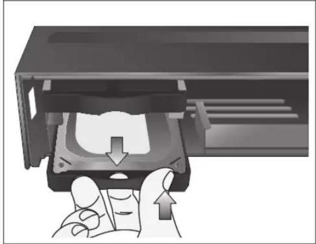
Hold the middle section of HDD bracket's handle with index finger and pull it forward while supporting the bracket handle with your thumb and middle finger as shown in the illustration.
natural_image
3D diagram of an open electronic device showing internal components and labeled parts (a and b), no text or symbols present.
natural_image
Illustration of a computer case with internal components and a hand inserting a device (no text or symbols visible)
natural_image
Hand inserting a device into a hard drive into a computer chassis (no text or symbols visible)
Once the HDD bracket is separated from the main unit, remove 4 screws on both ends of HDD bracket to separate the HDD from the bracket.
Install a new HDD and fasten the 4 screws back to both ends of the bracket.
When installing HDD, make sure to install in the correct direction.
text_image
DVR Assembly
Direction
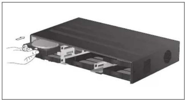
Push the bracket (with new hard drive installed) back into the main unit until it is completely inserted.
natural_image
Illustration of a computer drive with internal components and a hand inserting a cable (no text or symbols)
Assemble the front panel back to the unit.
Fasten the 2 screws on both ends of the main unit.
natural_image
3D diagram of an open electronic device showing internal components and two rectangular housing (no text or symbols)
VT-SRP Installation
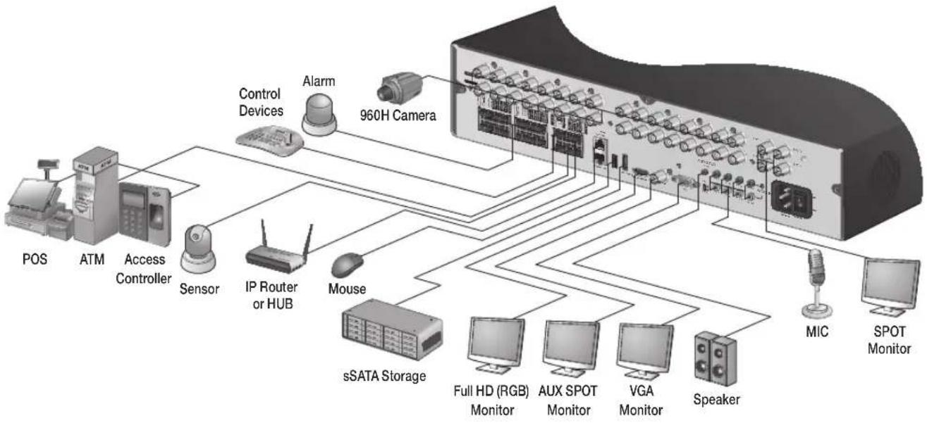
Basic Layout
flowchart
graph TD
    A["POS"] --> B["ATM"]
    B --> C["Access Controller"]
    C --> D["Sensor"]
    D --> E["IP Router or HUB"]
    E --> F["Mouse"]
    F --> G["sSATA Storage"]
    G --> H["Full HD (RGB) Monitor"]
    G --> I["AUX SPOT Monitor"]
    G --> J["VGA Monitor"]
    G --> K["Speaker"]
    K --> L["MIC"]
    K --> M["SPOT Monitor"]
Cable quality and distance can directly effect the video quality. it is recommended to consult an authorized installer when installing the DVR.
Connecting to an external device
Connecting to the monitor
This product supports 1080p 60 Hz HDMI monitors and regular monitors that support DVI and VGA inputs. Connect an HDMI cable to the port on the product's rear bottom, or connect an HDMI-DVI converter cable to connect a DVI monitor. Or, use VGA cable to connect the product with a VGA monitor.
- Once the product is set for NTSC or PAL output, connect cameras of the corresponding video standard for proper operations.
Setting the product to NTSC or PAL decides available display output modes too.
If set to PAL, the monitor must be able to display at 50Hz. For NTSC setting, it displays at 60 Hz.
- Make sure to connect the product to a monitor that supports 1920x1080 at 60Hz. (HDMI, DVI, VGA)
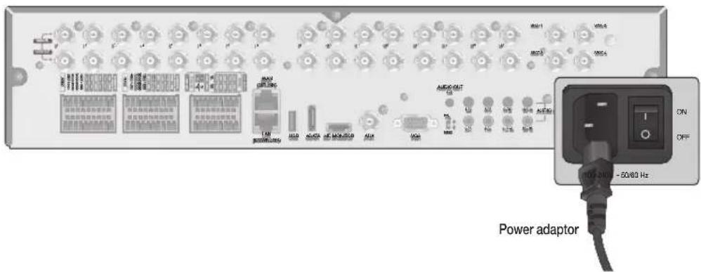
Power Connection
Plug the provided power cord to the rear power port of the DVR.
text_image
Power adaptor
ON
OFF
100A-2400 - 50/60 Hz
Do not place the power cord under the carpet or rug. The power cord is usually earth-grounded. However, even if it's not earth-grounded, do never modify it on your own for earth-grounding.
Do not insert multiple devices in a single power socket. Otherwise, it may cause a power overload.
VT-SRP Installation
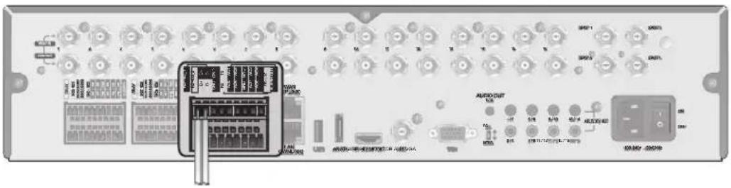
Alarm I/O Connection
To connect the alarm input signal
text_image
Diagram of an electronic device rear panel with labeled ports, connectors, and control buttons
Connect the signal line of an alarm input device such as sensor to the rear [ALARM IN] port.
Loosen the screws on both the alarm input port and [GND] port of the provided terminal block plug.
Insert one end of alarm signal cable through the [AO1] or [AO8] terminal hole below the screw hole, and then fasten the screw.
Insert the ground signal wire into the hole of the [GND] port (shown also below the screw), and tighten the screw.
To check proper insertion of cable, stop pushing and gently pull the cable and test whether it disconnects. To disconnect a cable, push the bottom side of the terminal and pull out the cable.
To connect the alarm output signal
Connect the signal line of an alarm output device to the rear [RELAY] port.
Loosen the screws on the [NO] and [NC] ports and the [COM] port of the provided terminal block plug.
2. Insert the alarm signal wire into the hole of the [NO] or [NC] input port (shown below the screw), and tighten the screw. Check the relay output type of Normal Open or Normal Close before selecting a proper type (NO or NC).
NO(Normal Open): Normally Open but switches to Closed if an alarm out occurs.
COM : Insert the grounding wire.
NC(Normal Close) : Normally Closed but switches to Open if an alarm out occurs.
Insert the ground signal wire into the hole of the [COM] port (shown also below the screw), and tighten the screw.
Or, you can connect the signal cable of the alarm output device to the [ALARM OUT] port on the rear side.
Loosen the screws on the [AO1] and [AO8] ports and the [GND] port of the provided terminal block plug.
Insert the alarm signal wire into the hole of the [AO1] or [AO8] input port (shown below the screw), and tighten the screw.
Check the relay output type of Normal Open or Normal Close before selecting a proper type (NO or NC).
Insert the ground signal wire into the hole of the [GND] port (shown also below the screw), and tighten the screw.
To check proper insertion of cable, stop pushing and gently pull the cable and test whether it disconnects. To disconnect a cable, push the bottom side of the terminal and pull out the cable.
Install the wire-connected terminal block in the rear port.
Communication Port
text_image
Back panel of an electronic device showing labeled ports, modules, and a central control panel with Chinese text.
RS-485 Connection
Connect a PTZ Camera or Keyboard Controller.
You can connect a text-in device such as POS or ATM (future firmware release).
After connecting the control device, be sure to match the connection settings between DVR and device.
Make communication settings in .
Connect the positive (+) transmission signal cable of the PTZ camera/keyboard controller to the RS-485 [D+] communication port on the DVR's rear panel..
Connect the negative (-) transmission signal cable of the PTZ camera/keyboard controller to the RS-485 [D-] communication port on the DVR's rear panel.
Connect the [GND] port of the terminal block plug and the [GND] port of the keyboard controller.
For RS-485 communication configuration, refer to the user's manual of the applicable PTZ camera or keyboard controller.
RS-232 Connection
You can connect PTZ cameras, POS or ATM devices (future firmware release).
For connection of the text-in device, refer to the user manual of the text-in device.
Audio Device Connection
Connect an audio input device such as a microphone to the rear Audio In port; connect an audio output device such as an amplified speaker to the Audio Out port.
VT-SRP Installation
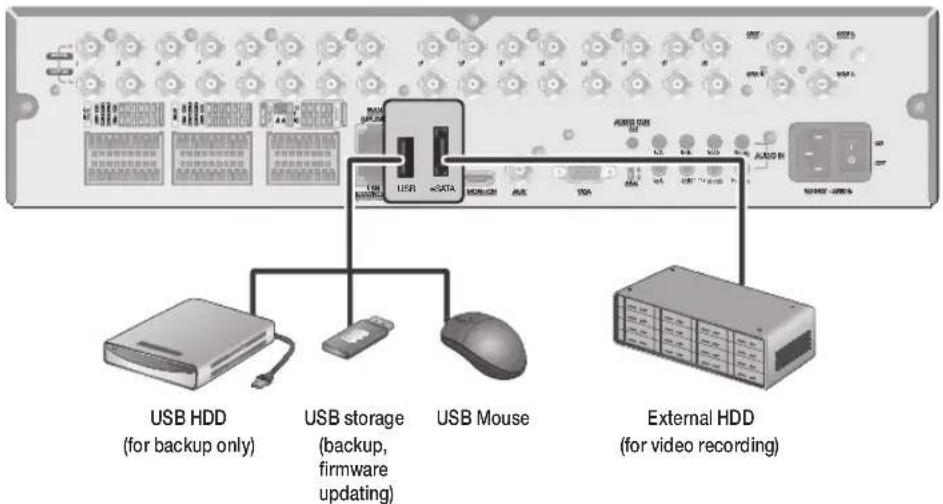
Storage and Mouse Connection
eSATA Storage
text_image
USB HDD
(for backup only)
USB storage
(backup,
firmware
updating)
USB Mouse
External HDD
(for video recording)
If the internal storage space is insufficient, you can extend your storage capacity by adding an eSATA storage device to the rear eSATA port.
- Using devices other than the recommended eSATA products may cause serious problem.
USB Device
You can connect and use USB storage devices for backup of recorded video, saving snapshots, firmware updating, importing/exporting user configurations. Also, USB mouse can be connected for DVR manipulations.
- If you need to connect a USB HDD with a high power consumption, it is recommended to use a separate power source for that HDD.
√ 20GB file size limit for backups
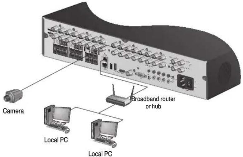
Network Connection
PC connection in the local network
You can connect the DVR to a PC in the same local area network.
text_image
Camera
Broadband router
or hub
Local PC
Local PC
Connect the [WAN(UPLINK)] port in the rear panel to the router or hub.
The LAN (DOWN LINK) port is only for a dedicated backup network device. (Do not connect devices to this port.)
Connect the local PC to the same router or hub.
text_image
USB
XJ2400
COSCO-PC
Broadband router
or hub
PAM HMI
Local PC
Local PC
Enter the address in the Web browser of your PC in the format of: "http://IP address:Web service port" (Ex : http://192.168.0.23:8080) The web service port is set to 8080 by default. From the Network Setup screen, you can change the port number.
If using the dedicated PC S/W, refer to the user manual of the program.
Enter the DVR's username and Password to log in. Factory default is ADMIN / 1234
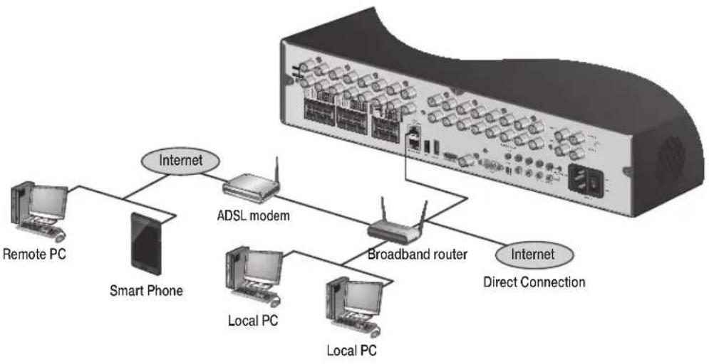
VT-SRP Installation
PC connection from a remote network
You can connect DVR to a PC or mobile device in the same remote network and control or manipulate it on the monitor of the PC or mobile device.
flowchart
graph TD
    A["Server"] --> B["ADSL modem"]
    B --> C["Broadband router"]
    C --> D["Remote PC"]
    C --> E["Local PC"]
    C --> F["Smart Phone"]
    C --> G["Local PC"]
    C --> H["Internet Direct Connection"]
    style A fill:#f9f,stroke:#333
    style B fill:#ccf,stroke:#333
    style C fill:#cfc,stroke:#333
    style D fill:#fcc,stroke:#333
    style E fill:#cff,stroke:#333
    style F fill:#ffc,stroke:#333
    style G fill:#fcc,stroke:#333
    style H fill:#ffc,stroke:#333
Connect the [WAN(UPLINK)] port in the rear panel to the router.
The LAN (DOWN LINK) port is reserved and only for servicing and development. (Do not connect devices to this port.)
flowchart
graph TD
    A["ADSL modem"] --> B["Broadband router"]
    B --> C["Local PC"]
    B --> D["1.0-NC Interface"]
    D --> E["Internet"]
    style A fill:#f9f,stroke:#333
    style B fill:#ccf,stroke:#333
    style C fill:#cfc,stroke:#333
    style D fill:#fcc,stroke:#333
    style E fill:#ffc,stroke:#333
Connect the [WAN(UPLINK)] port of the router directly to the fixed IP LAN cable, or connect it to the ADSL modem.
If using the router, set the port forwarding and enter the DDNS address in the address bar (web browser) of the remote PC, or of the dedicated software program or mobile phone.
For the IP and DDNS address settings, refer to "Network Setup". (page 46)
If the MAC address of the DVR is 00-11-5F-12-34-56 and the web port number is 8080, enter "http://00115f123456.dvrlink.net:8080" in the address bar of the web browser.
If you have renamed DDNS as "mydvr", you can make network connection at http://mydvr.dvrlink.net:8080.
Notes
Notes
Monitoring
START
Connect the 110V power input to the rear panel of the DVR.
The logo screen appears several seconds after the front LED turns on.
When the booting process is completed, the login screen appears.
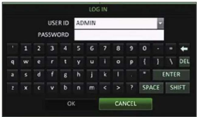
Log In
When the system starts, the login screen appears.
Select a user and provide the password.
The default USER ID is: "ADMIN" and the PASSWORD is: "1234".
Click .
- For safe and secure use of the product, change the password after purchasing.
text_image
LOG IN
USER ID ADMIN
PASSWORD
' 1 2 3 4 5 6 7 8 9 0 - = ←
q w e r t y u i o p { } \ DEL
a s d f g h j k l . * ENTER
z x c v b n m < > ? SPACE SHIFT
OK CANCEL
Log Out
To prevent unauthorized access, it is recommended to log out when you leave the screen.
In the live monitoring screen, click
While logged out, Search / Backup / System Settings / Record Settings / Exit menus are restricted.
text_image
Screenshot of a surveillance camera interface with multiple surveillance cameras and system setup thumbnails, including 'DOCK' and 'SHUTDOWN' options.
System Shutdown
In the monitoring screen, click
- If you turn off the system in an abnormal manner such as removing the power cord while the system is in operation, the disk can be damaged, causing data loss and shortened life cycle of the disk.
Shutdown turns off Disk and Operations. The DVR will ask to disconnect power to the unit (on the SRP, turn the power switch next to the 110 power cord input to OFF)
text_image
SHUTDOWN
USER ID ADMIN
PASSWORD
' 1 2 3 4 5 6 7 8 9 0 - =
q w e r t y u i o p { } \ DEL
a s d f g h j k l . * ENTER
z x c v b n m < > ? SPACE SHIFT
OK CANCEL
Monitoring
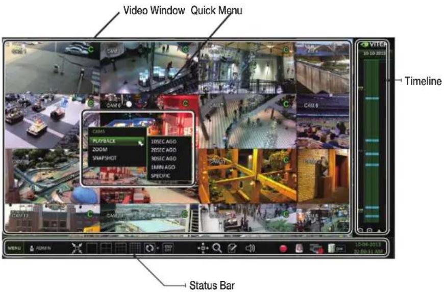
Live Screen At a Glance
The live screen largely consists of three components: video window, status bar and timeline.
text_image
Video Window Quick Menu
CAM 6
CAM 5
PLAYBACK
200M
SNAPSHOT
10SEC AGO
20SEC AGO
30SEC AGO
40MIN AGO
SPECIFIC
Timeline
VITEA
05-10-2013
10-04-2013
10:00:11 AM
MENU ADMIN
Status Bar
Video Window
Icons used in the video window.
Item Description
Camera ID
CAM1
Show the camera ID.
Record Mode Icons
Displayed if an event recording is reserved.
C
Continuous Recording.
A
Alarm Recording.
M
Motion Recording.
P
Panic (Emergency) Recording.
Audio I/O Icons
Audio Output
Motion Detection Icon
Motion is detected by the connected camera.
Status Bar
Press the [▼] button on the remote control, or place the mouse in the lower area of the screen to display the status bar.
Item Description
Menu Button
Allows access to the DVR's menu system
User ID
Show the ID of the currently logged in user
Screen Control Buttons
Edit the screen layout to show the status bar and timeline at all times or only when the mouse cursor hovers on the status bar/timeline.
Select various display modes
Select Auto Sequence Mode.
Display or hide the OSD menu on the screen.
PTZ
Launches the PTZ control screen.
Zoom
Digital Zoom.
Quick Log
Displays the log list of the recent recording events.
Audio Channel Selection Button
Select the audio input to listen to.
Panic Record
Start/stop panic recording.
Alarm Indicator
Tums on if a predetermined alarm event occurs.
Network Connection Status
Click this to view the current users remotely logged into the DVR, and to check the network connection status. For more information, refer to "Network Setup". (page 43)
Disk Space
If you have set the disk overwrite mode, it will be displayed "OW". Click this to view the details of the disk status. For more information, refer to "Record Setup". (page 60)
Date & Time Display the current date and date.
Monitoring
Timeline
Press the [▶] button on the remote control or move the cursor to the right of the screen to display the timeline. Double-click the timeline to move to the video screen. Drag and drop it to make backup or event search for the specified area.
Item Description
Timeline Date
Displays the date of the current timeline.Click this to select a desired date of the timeline.
Expand/Collapse the timeline
Expand or collapse the timeline.
Navigation through Timeline
Navigate through the timeline.You can also use the mouse wheel.
Timeline Bar
Displays the recording data with time. The color of each bar indicates the following:-Green: Continuous Recording-Red: Alarm Recording-Blue: Motion Recording-Yellow: Panic Recording
Quick Menu
Right click on a channel to display a quick menu popup window.
Item Description
Channel No Displays the number of the current channel.
Playback Starts playing the video of the selected channel from the specified time.
Zoom Operates (digital) zoom on the selected channel.
Snapshot
Captures the current live video and saves it in .jpeg format.
Using the status bar in the live mode
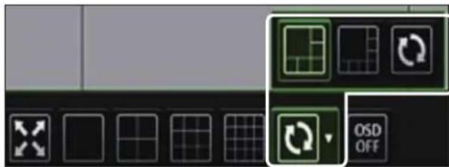
Selecting a Split Mode
Click a desired split mode from 1, 4, 9 and 16 split screen. Or press the [DISPLAY] button on the remote control until a desired split mode is displayed.
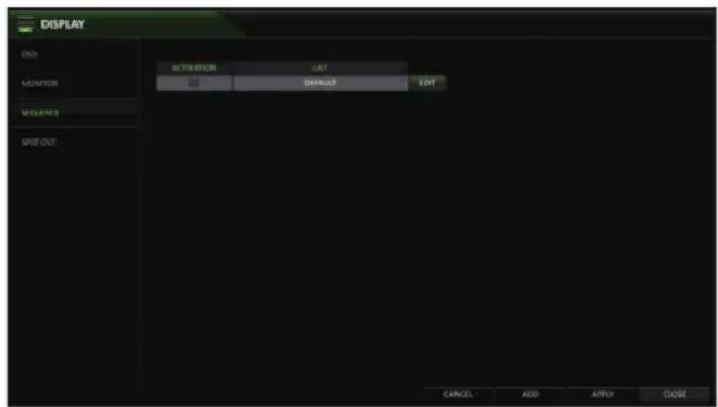
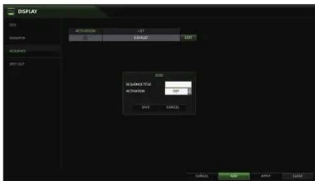
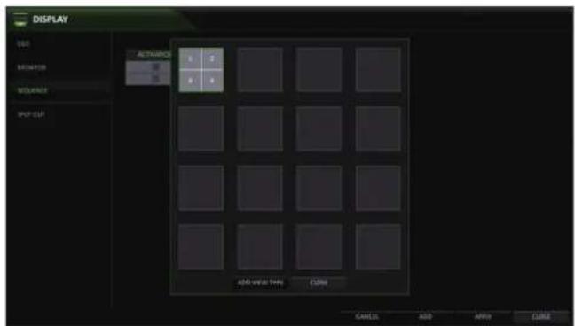
Auto Sequence
Click the Sequence button in the status bar, or press the [SEQ] button on the remote control. You can configure the sequence settings in .
For details, refer to "Sequence". (page 64)
natural_image
Pure graphical icons for grid and rotation symbols without any text or labels
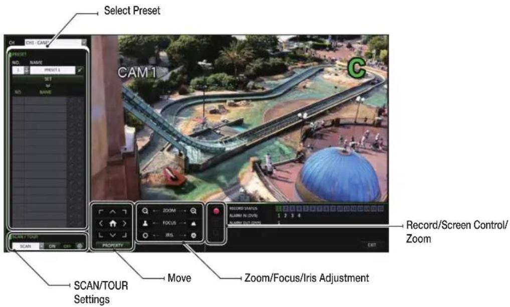
Controlling a PTZ
To control a PTZ camera, select the channel, then click PTZ button on the status bar, or press the [PTZ] button of the remote control to.
In PTZ mode, use the directional buttons to control the PTZ. Use [ZOOM], [FOCUS], [IRIS], [PRESET], and [SCAN/TOUR] to make adjustments to PTZ.
text_image
Screenshot of a software toolbar with icons and labels, including grid, rotation, and OSD OFF button
natural_image
Four black-and-white interface icons: zoom, document, speaker, and radio (no text or symbols)
You can enlarge the monitoring screen for better view.
Zooming will enlarge the video of the selected channel. If no channel is selected, channel 1 will be zoomed.
Click Zoom in the status bar or move the cursor to a desired channel and right-click it to display the context menu. Select . You can also press the [ZOOM] button on the remote control.
When the menu bar appears in the right bottom, use the buttons to control the zooming.
CH1 - CAM1 : Select a channel to zoom in/out.
: Zoom out the current (enlarged) image step by step.
: Enlarge the current image step by step.
Zoom Box : Use the yellow box to move to or select a desired zooming area.
EXIT : Exit the zooming screen and return to the live screen.
Digital zooming magnifies the video image digitally and produces enlarged images that may not be sharp and clear. For sharper and clearer magnification, it is recommended to use cameras supporting optical zooming.
text_image
0 CAM 10
19 8
SAVE
C
Event Log
You can check the log of the events that occurred.
Click Log to display the "EVENT LOG" window. The log list is sorted with the most recent event on top.
Double-click a desired event to display the video.
text_image
Screenshot of a surveillance camera interface displaying multiple aerial and outdoor scenes with Chinese labels like 'CAY 6' and 'EVENT LONG'.
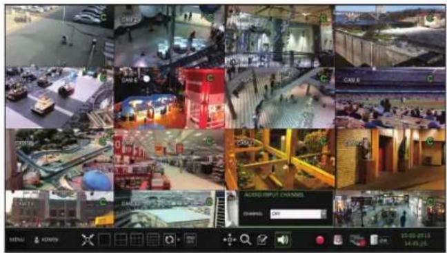
Select an Audio Input Channel
Select a channel from which the audio signal will be received.
CHANNEL : Produces the selected channel's audio, regardless of the split screen mode.
LINK TO FULL SCREEN : When switching the DVR display mode to view one channel (Single Split), it produces the selected channel's audio.
text_image
Collage of surveillance cameras and display screens showing various urban scenes with Chinese labels like 'CAN' and 'AUTO INPUT CHANGES'
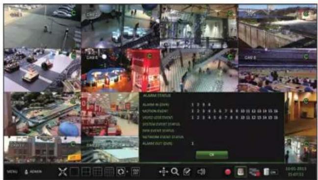
Check the Alarm Status
You can check alarms and events from each camera and the system. Click to close the window.
Check the Network Status
Shows the connection status of cameras and network devices. Click to close the window.
For more information, refer to "Network Status". (page 75).
text_image
ALAMN STATUS
ALAMN IN EQUITY 1 2 3 4
VASCION EVENT 1 2 3 4 5 6 7 8 9 10 11 12 13 14 15 16
VEGET GESTMENT 1 2 3 4 5 6 7 8 9 10 11 12 13 14 15 16
SPECTRAN EVENT STATUS
TOMEN EVENT STATUS
ALAMN OUT (OUT) 1
OK
MENU & ADMIN
16-03-2013
05:47:01
flowchart
graph TD
    A["ACCOUNT"] --> B["CLIENT"]
    B --> C["PROSPECTS"]
    C --> D["0-ADJUSTED"]
    D --> E["SNC ADJUSTED"]
    E --> F["SNC ADJUSTED STATUS"]
    F --> G["SNC ADJUSTED STATUS"]
    G --> H["CONTENTS: 19-05-2023 19:48:31"]
    H --> I["CONTENTS: 19-05-2023 19:48:31"]
    I --> J["CONTENTS: 19-05-2023 19:48:31"]
    J --> K["CONTENTS: 19-05-2023 19:48:31"]
    K --> L["CONTENTS: 19-05-2023 19:48:31"]
    L --> M["CONTENTS: 19-05-2023 19:48:31"]
    M --> N["CONTENTS: 19-05-2023 19:48:31"]
    N --> O["CONTENTS: 19-05-2023 19:48:31"]
    O --> P["CONTENTS: 19-05-2023 19:48:31"]
    P --> Q["CONTENTS: 19-05-2023 19:48:31"]
    Q --> R["CONTENTS: 19-05-2023 19:48:31"]
    R --> S["CONTENTS: 19-05-2023 19:48:31"]
    S --> T["CONTENTS: 19-05-2023 19:48:31"]
    T --> U["CONTENTS: 19-05-2023 19:48:31"]
    U --> V["CONTENTS: 19-05-2023 19:48:31"]
    V --> W["CONTENTS: 19-05-2023 19:48:31"]
    W --> X["CONTENTS: 19-05-2023 19:48:31"]
    X --> Y["CONTENTS: 19-05-2023 19:48:31"]
Monitoring
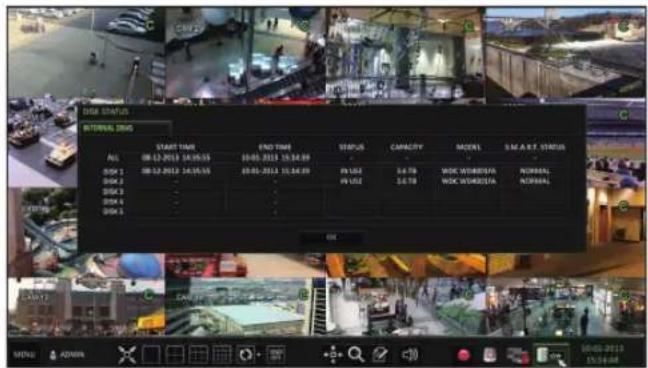
Check the Disk Status
You can check status and information on storage devices currently connected to the system.
Click to close the window.
For more information, refer to "Disk Information". (page 103).
text_image
DISE STATUS
INTERNAL DNO
START TIME
DATE: 08-12-2013 04:35:55
ISSN 1
ISSN 2
ISSN 3
ISSN 4
ISSN 5
END TIME
08:00-2013 15:34:09
08:05-2013 15:34:09
IN USE
IN USE
CAPACITY
3.679
3.678
MODES
MODE WORKERS
MODE WORKERS
NORMAL
NORMAL
OK
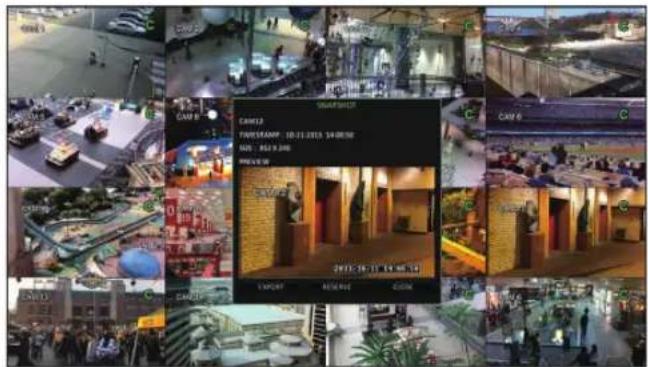
Saving Captured Snapshots
You can capture the current video screen and save or export it to a connected storage device.
Select a channel first, and right click on mouse to open popup menu, and select menu item, or press the [SNAPSHOT] button of the remote control.
text_image
Collage of surveillance camera feeds showing smart home, smart check-up, and outdoor scenes with Chinese labels
Connect a storage device, and click the button.
To save the captured image to the built-in HDD, press the button.
Saved image can be found in the "Archive > Reserved data management" and can be backed up later. (Page 101)
A progress bar appears and indicates the progress of exporting to storage device.
BURN: Snapshot is stored in the connected USB storage device.
ERASE & BURN : Deletes all files in the connected USB storage and then saves the snapshot.
Note that option erases all data on the USB storage device.
System Setting
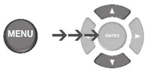
To move to the System Setup menu
How to use the mouse
text_image
MENU
text_image
SEARCH
ARCHIVING
SYSTEM SETUP
RECORD SETUP
LOG OUT
SHUTDOWN
How to use the remote control 1
flowchart
graph LR
    A["MENU"] --> B["ENTER"]
    style A fill:#999
    style B fill:#ccc,stroke:#333
text_image
SEARCH
ARCHIVING
SYSTEM SETUP
RECORD SETUP
LOG OUT
SHUTDOWN
text_image
ENTER
How to use the remote control 2
System Setting
Camera Setting
You can configure the display settings of: camera title, hidden option, motion and camera type.
CAMERA TITLE
You can change the camera ID that is displayed on the screen.
From
Use the [▲▼◄►/ENTER] buttons on the remote control or use the mouse to select a channel that you want to rename.
Alternatively, simply double-click the camera to rename from the top left corner.
Once the virtual keyboard appeared, select desired alphanumeric characters to complete your input, and press the button.
The key toggles letter case.
To apply the change, click at the bottom of the screen.
When done, press the [EXIT] button on the remote control or click in the lower screen. A confirmation message appears and you will return to the previous menu.
For the SRE and SRP models, camera titles can be up to 16 characters, combining numbers and upper/lower case letters. (no spaces). For the SRL model, camera titles can be up to 8 characters.
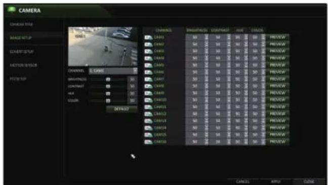
Image Setup
You can adjust the brightness, contrast, color, and quality setting of each channel's camera.
From
Use [▲▼◄►/ENTER] buttons of the remote control or mouse to edit settings.
To apply your changes, click button.
Once completed, press the [EXIT] button of the remote control or click the button on the bottom of the screen. A confirmation dialog appears and returns to the previous menu.
text_image
CAMERA
CHANNEL SIZE
MANGE SETUP
GARANT SETUP
LASTION SETUP
F22.00: 100
CHANNEL: 3. CAME
LENGTH: 50
DEPTH: 50
HIA: 50
COLOR: 50
DEFAULT
CHANNELS
CAMA1
CAMA2
CAMA3
CAMA4
CAMA5
CAMA6
CAMA7
CAMA8
CAMA9
CAMA10
CAMA11
CAMA12
CAMA13
CAMA14
CAMA15
CAMA16
PRO numbered: 50
PRO numbered: 50
PRO numbered: 50
PRO numbered: 50
PRO numbered: 50
PRO numbered: 50
PRO numbered: 50
PRO numbered: 50
PRO numbered: 50
PRO numbered: 50
PRO numbered: 50
PRO numbered: 50
PRO numbered: 50
PRO numbered: 50
PRO numbered: 50
CABLES
APPLE
CLOSE
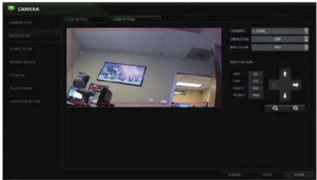
Crop Setting
On the SRE/SRPmodels you can crop camera images.
From
Select the channel you wish to crop, then in the BOX POSITION section use the “-” and “+” and directional arrows to move the crop box. When finished, turn OPERATION to ON.
To apply your changes, click button.
Once completed, press the [EXIT] button of the remote control or click the button on the bottom of the screen. A confirmation dialog appears and returns to the previous menu.
text_image
CAMERA
COLOR SETTING
COFFETTING
CHANNEL: L GAMES
ORIENTATION: OFF
RAW COLOR: 100%
RUNPTION:
LEFT 42
TOP 61
SHIFT 800
BEANS 900
CANCEL: OK/OK
CANCEL: OK/OK
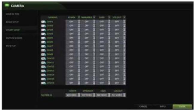
Covert Setup
You can make selected cameras "covert" so that specific users or user groups can not view the camera images.
Use the [▲▼◄►/ENTER] buttons on the remote control or use the mouse to select a covert channel(s) for a specific user group.
ADMIN, MANAGER, USER : Set them to . The selected channel(s) will be covert from the applicable user account.
LOG OUT : Set it to . When the user logs out, the current channel will be set to a covert channel.
From
To apply the change, click in the bottom of the screen.
When done, press the [EXIT] button on the remote control or click in the lower screen. The confirmation message appears and you will return to the previous menu.
To set specific channels to COVERT for specific users, go to [USER], [MANAGEMENT], and select a USER ID. On the EDIT screen, you can assign what cameas are COVERT.
text_image
CAMERA
CAMERA LIST
CHANNEL
AVEN
VANUEER
LINE
SEC OUT
AVEN
AVEN
AVEN
AVEN
AVEN
AVEN
AVEN
AVEN
AVEN
AVEN
AVEN
AVEN
AVEN
AVEN
AVEN
AVEN
AVEN
AVEN
AVEN
AVEN
AVEN
AVEN
AVEN
AVEN
AVEN
AVEN
AVEN
AVEN
AVEN
AVEN
AVEN
AVEN
AVEN
AVEN
User can assign camera channel to display "Covert" or "No Video" while in covert mode
System Setting
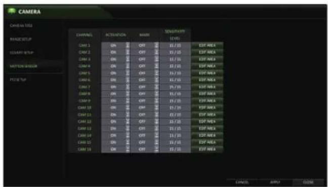
Motion Sensor
Set the motion sensor of the camera.
From
Use the [▲▼◄►/ENTER] buttons on the remote control or use the mouse to specify the use of each option item.
ACTIVATION : turn on or off the motion sensor.
MARK: Set to to display the motion detection indicator on each video tile.
SENSITIVITY : Set the sensitivity level of the motion sensor to either Daytime or Nighttime.
EDIT AREA : Specify the motion detection area.
text_image
CAMERA
Candescent
CHANNEL
RECOVATION
MAYA
SUPPORT
(KEY)
CAM 1
ON
OFF
15/10
Export Area
CAM 2
ON
OFF
15/10
Export Area
CAM 3
ON
OFF
15/10
Export Area
CAM 4
ON
OFF
15/10
Export Area
CAM 5
ON
OFF
15/10
Export Area
CAM 6
ON
OFF
15/10
Export Area
CAM 7
ON
OFF
15/10
Export Area
CAM 8
ON
OFF
15/10
Export Area
CAM 9
ON
OFF
15/10
Export Area
CAM 10
ON
OFF
15/10
Export Area
CAM 11
ON
OFF
15/10
Export Area
CAM 12
ON
OFF
15/10
Export Area
CAM 13
ON
OFF
15/10
Export Area
CAM 14
ON
OFF
15/10
Export Area
CAM 15
ON
OFF
15/10
Export Area
To apply the change, click in the bottom of the screen.
When done, press the [EXIT] button on the remote control or click in the lower screen. The confirmation message appears and you will return to the previous menu.
- The motion detection sensitivity may differ depending on the characteristics of the connected camera or the installation environment.
Motion Area Setup
From the motion sensor window, click to display the area setup screen.
Click to move to the motion area setup screen.
If using the remote control, press the [ENTER] button to initiate the process.
Use the arrow buttons to move to a desired block and press [ENTER]. The area setup will begin.
Then, use the arrow buttons to specify the area. Press [ENTER] to select/deselect the area.
Alternatively, when using a mouse you can use the drag-and-drop method to specify or release the area.
If you select the specified area again, it will be released.
text_image
CHANNEL
SELECT ALL
DESELECT ALL
SENSITIVITY
SAVE
SAVE & ENT
CANCEL
1 CAME1
2 CAME2
3 CAME3
4 CAME4
5 CAME5
6 CAME6
7 CAME7
8 CAME8
9 CAME9
10 CAME10
11 CAME11
12 CAME12
13 CAME13
14 CAME14
15 CAME15
16 CAME16
Red Block = Selected area. The screenshot above shows the entire screen selected. These blocks are what triggers the motion sensor.
Press the [EXIT] button on the remote control or right-click any area to display the popup window as in the right picture.
While the popup window is displayed, select to set the motion detection sensitivity of the channel currently selected.
Channel: Select the channel to set the motion sensitivity.
- SENSITIVITY : 1(Low) \~ 30(High) - The higher the number is, the higher the sensitivity level becomes.
DAYTIME : specify the time period that will be considered as daytime.
DAYTIME : specify the for the daytime.
NIGHTTIME : specify the for the nighttime.
Images recorded in a low contrast scene such as at night can cause severe noise, which can trigger motion events too often.
If unwanted events occur frequently at night, you may want to reduce the motion sensitivity for the nighttime setting.
Set the camera ID, protocol, baud rate, and PTZ control speed for each channel.
Use [▲▼◄►/ENTER] buttons of the remote control or mouse to set protocol and baud rate of each channel.
From
Refer to the camera's manual or consult your installation technician for further information about your PTZ camera.
To apply your changes, click the button.
Once the setup has been completed, press the [EXIT] button of the remote control or click button on the bottom. Click to return to the previous menu.
text_image
CAMERA
CAMERA TYPE
CHANNEL
RESIDENT
PROTECTS
MAX. RATE
C01
B
VTER
MIN
9000
MIN
C02
B
VTER
MIN
9000
MIN
C03
B
VTER
MIN
9000
MIN
C04
B
VTER
MIN
9000
MIN
C05
B
VTER
MIN
9000
MIN
C06
B
VTER
MIN
9000
MIN
C07
B
VTER
MIN
9000
MIN
C08
B
VTER
MIN
9000
MIN
C09
B
VTER
MIN
9000
MIN
C10
B
VTER
MIN
9000
MIN
C11
B
VTER
MIN
9000
MIN
C12
B
VTER
MIN
9000
MIN
C13
B
VTER
MIN
9000
MIN
C14
B
VTER
MIN
9000
MIN
User will need to connect the PTZ camera(s) to the DVR's RS-485 ports on the rear panel.
System Settings
TAMPER DETECTION - (SRE/SRP ONLY)
Redirection, Blockage, and Defocusing of the camera(s) have been combined into the Tamper Detection function that has a simple On/Off Activation button in the menu
Select from
Set the activation of each channel,
ACTIVATION : Set the detection for each channel to be enabled/disabled
MARK: Turns on or off the detection indicator to be displayed on the screen
LEVEL: The detection sensor's sensitivity; This can be separately set for day / night modes
When done, press the [EXIT] button on the remote control or click in the lower screen. The confirmation message appears and you will return to the previous menu.
For more features, please see -
PRIVACY MASK - (SRE/SRP ONLY)
Allows users to block out specific areas of camera image
Select from
Set the activation of each channel in the ACTIVATION tab.
ACTIVATION : Set to on for each camera channel that will utilize the featureMARK: Turns on or off the detection indicator to be displayed on the screen
• MASK COLOR: Choose the Privacy Mask color
Set the activation of each channel in the ACTIVATION tab.
Use the mouse to click-and-drag to select the designated masking areas. User can select up to 4 different areas per camera channel.
When done, press the [EXIT] button on the remote control or click in the lower screen.
The confirmation message appears and you will return to the previous menu.
You can configure screen display setup for the On-screen Display, Sequence, and SPOT Out.
OSD
You can set the Camera Name, Icon, Status Bar, Timeline, Borderline, User Name and Language.
From
Use the [▲▼◄►/ENTER] buttons on the remote control or use the mouse to set each option of the OSD item.
CAMERA TITLE : specify the display of the camera title on the screen.
RECORDING MODE ICON : shows/hides the record mode icon on the screen.
STATUS BAR ON FULL SCREEN MODE : select to show or hide the status bar in full screen mode.
-AUTO HIDE: move the cursor to the lower area of the screen to display the status bar. When moving the cursor up, the status bar will disappear.
- ALWAYS ON : The status bar will be displayed at all times.
- 5 SEC \~1 MIN : If no mouse movement is detected from 5 seconds to 1 minute, the status bar will disappear.
TIMELINE ON FULL SCREEN MODE : shows/hides the timeline in full screen mode.
AUTO HIDE : move the cursor to the right margin to display the timeline. Move the cursor to the left to hide the timeline.
ALWAYS ON : The timeline will be displayed at all times.
ALWAYS OFF : The timeline will not be displayed.
BORDER LINE : displays the cross-border between channels in split mode
BORDER COLOR : select a color for the border.
USER NAME : displays the currently logged-in users on the status bar.
LANGUAGE : select a menu display language.
To apply the change, click in the bottom of the screen.
When done, press the [EXIT] button on the remote control or click in the lower screen. The confirmation message appears and you will return to the previous menu.
System Setting
Monitor
Adjust the dwell times for Sequence and Spot.
From
Use the [▲▼◄►/ENTER] buttons of the remote control or mouse to set the dwell times for Sequence mode and SPOT Out.
SEQUENCE DWELL: Sets the time interval to the next screen (Can set to 1 sec \~ 60 sec). Default is 5
SPOT DWELL : Sets the time interval to the next view type. (Can set to 1 sec \~ 60 sec) Default is 5
VIDEO ASPECT RATIO : User can specify the Aspect Ration; 16:9 or 4:3
text_image
DISPLAY
UID
INVOICE OUTPUT
2 MHz
2 MHz
2 MHz
DATA OUTPUT
DATA OUTPUT
DATA OUTPUT
OUTPUT
OUTPUT
OUTPUT
OUTPUT
OUTPUT
DISPLAY RESOLUTION : User can select the display resolution from the list: Auto, 1280x1024, 1280x720, 1920x1080
To apply the change, click in the bottom of the screen.
When done, press the [EXIT] button on the remote control or click in the lower screen. The confirmation message appears and you will return to the previous menu.
Sequence
Configure the sequence feature.
From
Use the [▲▼◄►/ENTER] buttons on the remote control or use the mouse to add a sequence or change the activation setting of the existing sequence.
ACTIVATION : Activates the selected sequence.
ADD : Add a sequence.
To apply the change, click in the bottom of the screen.
When done, press the [EXIT] button on the remote control or click in the lower screen. The confirmation message appears and you will return to the previous menu.
text_image
DISPLAY
END
MONITOR
VOLUME
UP/OUT
INFORMATION
OUT
DEFAULT
OUT
CANCEL
ADD
INPUT
CLOSE
To add a sequence
Click in the bottom of the screen.
When the "ADD" dialog appears, enter a title using the virtual keyboard. (8 Characters)
Enter the name of the sequence, set ACTIVATION to ON, then click .
Select Activation ON/OFF
Select .
When the "SEQUENCE SETUP" dialog appears, select a split mode that you want to add from .
When the selected split mode is displayed on , select a channel you want to display in each split screen.
Click . The set sequence mode is confirmed and will be added to the Sequence list.
When done, click in the bottom of the screen.
After the sequence type is saved, you will return to the previous screen.
text_image
DISPLAY
ACTUATION
LST
DISPLAY
EAT
ADDRESS
ADDRESS TITLE
ACTUATION
ADD
SAVE
CANCEL
CNCAL
ADD
APPT
COM
text_image
DISPLAY
OK
VENTOR
WELCOME
SPOT OUT
ACTIVATION
MESSAGE SETUP
VIEW TYPE
VIEW CONFIGURE
CONTROL
CANCEL
NEW VIEW TYPE
CODE
CANCEL
ADB
APPLE
TUBE
System Setting
To edit a sequence
Select a sequence that you want to edit in the list by clicking the button, or double-clicking the sequence title
The "EDIT" dialog appears.
Use the [▲▼◄►/ENTER] buttons on the remote control or use the mouse to edit the selected sequence.
SEQUENCE TITLE : enter a new sequence name.
ACTIVATION : Activates/Deactivates the sequence.
MODIFY : change the sequence settings.
DELETE : delete the selected sequence.
CANCEL: cancel the changes.
Pressing the button will display the Modify Sequence window.
To change the existing settings, select a screen mode that you want to edit and right-click to display the context menu. Then, select .
💬 Hi! I'm your manual assistant.I know your Vitek VT-SRP916.
How can I help you? (use, settings, error codes, maintenance, explaining a step from the manual, etc.)💡 Examples :
• How do I use it ?
• Error code E3 ?
• How do I clean it ?