
VT-H160 - Digital Video Recorder Vitek - Free user manual and instructions
Find the device manual for free VT-H160 Vitek in PDF.


| Product Type | Digital Video Recorder (DVR) |
| Brand | Vitek |
| Model | VT-H160 |
| Video Inputs | 16 channels, composite (BNC), NTSC/PAL |
| Video Outputs | 1 BNC, 1 VGA (selectable) |
| Compression | H.264 |
| Recording Resolution | Up to 704x480 (NTSC) / 704x576 (PAL) |
| Recording Frame Rate | Up to 120 fps (NTSC) at 352x240, up to 30 fps at 704x480 |
| Internal Storage | 1 SATA HDD, up to 1 TB |
| Operation Mode | Quadplex (simultaneous recording, playback, network, backup) |
| Alarm Inputs / Output | 4 sensor inputs (NC/NO) / 1 relay output (0.5A/125VAC, 1A/30VDC) |
| Network Interface | 10/100 Base-TX Ethernet (RJ-45) |
| Remote Access | Client software, web viewer, free DDNS |
| Backup Methods | USB flash drive, network (PC) |
| Power Supply | DC 12V, 5A (adapter included), ~25W |
| Operating Temperature | 5°C to 40°C (41°F to 104°F) |
| Operating Humidity | 30% to 90% RH |
| Dimensions (W x H x D) | 340 x 262 x 63 mm (13.4 x 10.3 x 2.5 in) |
| Net Weight | 1.6 kg (3.1 lbs) |
| Gross Weight | 3.5 kg (6.8 lbs) |
| Remote Control | IR remote with battery (AAA x2) included |
| Firmware Upgrade | Via USB flash drive |
| Warranty (at 25°C) | HDD: 1 year, Fan: 1 year, Battery: 2 years |
| Maintenance | Keep vents clear; avoid dust accumulation; do not block fans |
| Safety | Use only supplied adapter; do not expose to rain/moisture; do not disassemble (high voltage inside) |
Frequently Asked Questions - VT-H160 Vitek
User questions about VT-H160 Vitek
0 question about this device. Answer the ones you know or ask your own.
Ask a new question about this device
Download the instructions for your Digital Video Recorder in PDF format for free! Find your manual VT-H160 - Vitek and take your electronic device back in hand. On this page are published all the documents necessary for the use of your device. VT-H160 by Vitek.
USER MANUAL VT-H160 Vitek
• 4, 8 or 16 Video Inputs with 1 BNC & 1 VGA Outputs
• H.264 Compression
• Supports both Dynamic and Static IP Addresses
- Up to 120 IPS Recording / Live Display
- Remote Viewing over the Internet or LAN
• Supports one internal SATA Hard Drive
• 250GB to 1TB Internal Storage Options
- Quadplex operation enabling simultaneous recording, playback, networking, and backup
• 4 Alarm Inputs / 1 Relay Out
• Control locally via Included IR Remote
- Backup via Ethernet or USB
SAFETY PRECAUTIONS

EXPLANATION OF SYMBOLS

This symbol is intended to alert the user to the presence of important operation and maintenance (servicing) instructions in the literature accompanying

This symbol is intended to alert the user to the presence of unprotected “dangerous voltage” within the product’s enclosure that may be strong enough to cause a risk of electric shock persons.
WARNING
To reduce the risk of fire or electric shock, do not expose this product to rain or moisture.
CAUTION
Changes or modifications not expressly approved by the manufacturer may void the user's authority to operate this equipment.
CAUTION
Danger of explosion if battery is incorrectly replaced.
Replace only with the same or equivalent type recommended by the manufacturer.

WARNING
- Do not use if the unit emits smoke, strange sounds are heard, or odor is emitted.
● Make sure the power cable is not damaged. - Make sure there is no dust accumulation on the pow outlet.
-
Disassembly prohibited
-
Do not place any foreign objects inside the unit.
- Do not place a container holding water or other liquids above the unit when it is connected to power.
- Do not allow the unit to get wet.
- Do not use during thunder/thunder storms unless used with an uninterruptable power supply (UPS).
- Do not place in an unstable position.
- Do not expose to shock or vibration.
- Do not use this unit in areas where it is exposed to the possibility of explosion.

CAUTION
- Do not pull on the power cable when removing the power plug from the outlet.
- Do not touch the power plug with wet hands.
- Do not sit on.
● Make sure the cables are connected properly. - Do not place heavy objects on connected units.
● Never move this unit while the power is turned on. - Do not block the cooling fans or air ducts.
- Do not expose to extreme temperatures or humidity changes.
Precautions for supplied AC Adaptor

CAUTION
- Never disassemble or modify.
- Never get the adaptor wet.
- Use only the supplied AC adapter.
- Do not connect to other appliances.
- Do not connect this unit with the AC adapter in areas reachable to children or where pets move freely.
- Never touch the AC adapter with wet hands.
- If the unit emits smoke, strange sounds or smells immediately remove the AC adapter from the outlet.
- Do not use during thunder/thunder storms unless used with an uninterruptable power supply (UPS).

CAUTION
- Make sure the cable is connected properly to prevent damage to the cable.
Main features
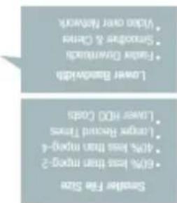
H.264 Video compression

Industry Leading H.264 Compression Codec
- QUADPLEX operation enabling simultaneous recording, playback, networking, and backup.
![graph TD A["Recording"] --> B["Network"] B --> C["Playback"] C --> A D["Backup"] --> B](/content/2026/05/1008175/images/18946c03e86da94cd18394e1753a9544b99552e2535f7cb1db50a52ec67e2036.jpg)
- Instant and convenient data backup & firmware upgrade using USB flash drive Simple User Interface
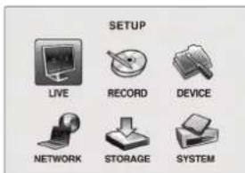
● Individual channel setting and operation
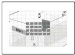
● Motion detection record
- Free Dynamic DNS
System components and Installation
Requirements for installation and safety
This chapter is for the requirements for safe installation and use.
This kit should be installed on a flat table or in a rack.
The location in which the DVR is installed in the room is very important for proper operation of the system. When the DVR is installed too closely together or the location is poorly ventilated, the DVR may not operate properly and maintenance of the DVR may be difficult. Make sure that the air should be sufficiently circulated within the system operating room and the cover of the main system must be tightly fastened to prevent malfunction.
There are high voltage parts inside. Do not open the cover during operation. The DVR must be installed in a place that meets the following environmental conditions.
- Operating temperature: 5°C 40°C (41°F \~ 104°F)
- Operating humidity: 30% 90% RH
- Input voltage: DC +12V 5A
• Power usage: About 25Watts
• Frequency: 60Hz/50Hz
Main replacement parts
- Hard disk (When HDD is factory-installed.): 1 year (25°C/77f environment)
• Cooling fan: 1 year (25°C/77f environment) - Battery: 2 years (25°C/77f environment)
CAUTION
During the operation of this product, the fluctuation of input voltage must be within 10% of the rated voltage and the external power outlet must be grounded, otherwise, it may cause electric shock or malfunction of the product.
Do not connect heat-generating appliances to the same power outlet in which the product is plugged, otherwise it may cause a fire or malfunction of the product.
The use of an Automatic Voltage Regulator (AVR) is highly recommended to ensure that stable power is supplied.
CAUTION
The HDD that is installed in DVR can be replaced or upgraded by and authorized VITEK Repair Center. Warranty will be void if unit is opened by unauthorized personnel.
Components
The package contains the main unit and its components as specified below. When you purchase the package, please check to ensure the components specified below are included.
| VT-H Series DVR |  |
| Remote Controller |  |
| Battery1.5V (AAA x 2EA) | [x7wx] |
| Adaptor and Power Cable |  |
| Client Software CD |  |
| Manual |  |
SPECIFICATIONS
| ITEM VT-H40 (4CH) VT-H80 (8CH) VT-H160 (16CH) | ||||||
| Video | Input | Channel, Input Level | 4CH, Composite | 8CH, Composite | 16CH, Composite | |
| Signal Format NTSC/PAL | ||||||
| Video Loss Check Yes | ||||||
| Output | Main Monitor Output 1 CH BNC, 1CH VGA: Selectable | |||||
| Signal Format NTSC/PAL & VGA | ||||||
| Audio Input & Output | - | |||||
| Alarm | Sensor Input ((NC/NO Selectable) | 4 | 4 | 4 | ||
| Alarm Output | 1 Alarm out by Alarm, Motion, Video Loss | |||||
| Record | Compression | H.264 | ||||
| Multi-operation | QUADPLEX (Playback/Record/Network/Backup) | |||||
| Resolution | NTSC | 352x240 | 352x240 | 352x240 | ||
| 704x240 | 704x240 | |||||
| 704x480 | 704x480 | 704x480 | ||||
| PAL | 352x288 | 352x288 | 352x288 | |||
| 704x288 | 704x288 | |||||
| 704x576 | 704x576 | 704x576 | ||||
| Recording quality grade | NETWORK, ECONOMY, NORMAL, HIGH, FINE. | |||||
| Recording Mode | Continuous / Schedule / Motion/ Sensor/ Manual | |||||
| Motion Detection | Motion detection setup by Grid | |||||
| Pre Recording | 1 fps for 5 seconds before an event | |||||
| Post Recording | 10 seconds to 3 minutes after an event | |||||
| Display | Frame Rate (/Sec) | NTSC: 30fps/ch, 60 fields / PAL: 25fps/ch, 50 fields | ||||
| Playback | Multi-Decoding | 1, 4 | 1, 4, 9 | 1, 4, 9, 16 | ||
| Playback Speed | Single channel | × 2, 4, 8 | ||||
| Multi-channels x 2, 4 | ||||||
| Search Mode Timeline, Event, Archive, Log | ||||||
| Storage | HDD | Interface Type Serial ATA I | ||||
| Capacity of 1 HDD 1 TB | ||||||
| Internal HDD Number | 1 1 1 | |||||
| File system NaFS | ||||||
| Backup | USB Flash drive Video & Still Image | |||||
| Network Video & Still Image | ||||||
| User I/F | Menu Display Text UI | |||||
| Input Method Remote control | ||||||
| PTZ control & Keyboard DVR control | - | |||||
| Network | Dynamic DNS | Yes (Free DDNS) | ||||
| Network Interface 10/100 base-TX Ethernet (RJ-45) | ||||||
| Network Access | Client Software (1:1) | Live, Search, Backup, PTZF Camera Control | ||||
| Web viewer (1:1) | Live, Search, Backup, PTZF Camera Control | |||||
| Multi-sites Monitoring System (1:n) | Live, Search, Backup, PTZF Camera Control | |||||
| Features | DLS (Day Light Saving) | Yes | ||||
| Internal Beep | By Alarm, Motion, Video Loss, HDD error | |||||
| Multi-Language | Yes | |||||
| S/W Upgrade USB Flash drive | ||||||
| Water - mark | Yes (Exclusive viewer) | |||||
| Power | Power | DC 12V 3A(for 4CH), DC 12V 5A(for 8,16CH) | ||||
| Weight | Unit Weight (Gross weight) | 1.6 Kgs (3.1 Lbs) / 3.5 Kgs (6.8 Lbs) | ||||
| Dimension | Unit Dimension (W x H x D) | 340 mm x 262 mm x 63 mm / 13.4" x 10.3" x 2.5" | ||||
INDEX
1. NAME & FUNCTION .... 10
1-1. Front panel....10
1-2. Remote controller .... 11
1-3. Rear panel and connection....12
1-3-1. Basic connections....12
2. SETTING UP THE DVR....15
2-1. Setup - Main Screen 15
2-2. Setup - Live Mode....17
2-3. Setup - Recording Mode 18
2-3-1. Motion Zones.... 19
2-3-2. Recording Schedules.... 20
2-4. System....21
2-5. Network....23
2-5-1. Ports 24
2-5-2. Network types.... 25
2-5-2-1. LAN 25
2-5-2-2. DHCP 25
2-5-2-3. ADSL (PPPOE).... 26
2-6. Storage 27
3. LIVE & SEARCH....29
3-1. Live Window....29
3-2. SEARCH window....30
3-2-1. EVENT Search.... 31
3-2-2. TIME LINE Search.... 32
3-2-3. GO TO 33
3-2-4. GO FIRST 34
3-2-5. GO LAST 34
3-2-6. LOG List 34
3-2-7. ARCHIVE Search.... 34
3-3. Playback mode 35
- ARCHIVING AND BACKUP......36
4-1. Archiving Still images or Video......36
4-2. Backup still images or videos on USB memory stick....37
4-3. Playing backup file....38
- NETWORK ACCESS USING THE NETWORK VIEWER 39
5-1. PC requirements....39
5-2. Installing the network viewer....39
5-3. Live monitoring mode and functions....41
5-4. Bi directional audio .... 43
5-5. Remote search mode and functions....44
5-6. PC System configuration 47
- NETWORK - BY A WEB-BROWSER VIEWER 50
APPENDIX: HOW TO CONNECT TO A NETWORK....53
A. How to set the IP address of the DVR and open the TCP port of the router? ..... 53
B. How to access the DVR from Remote PC? 55
1. NAME & FUNCTION
1-1. Front panel

Table 1.1. Front LED and USB Port
| Name | Description |
| POWER LED | D light is on when power is applied to the system. |
| HDD LED | light is on when the system is recording video data. |
| USB port | There is a USB port located on the left side of the front panel. This USB port is used to archive footage into a USB storage device. (USB 2.0 connector) |

1-2. Remote controller
① ID: When a remote control ID number is set in DVR, press it before number.
② REC: To start and stop manual recording.
③ Number: To select channel (1, 2, 3, & 4) or to enter DVR ID number.
④ F/REW: During playback - To move the playback position 60 seconds backward.
During pause - To move the playback position 1 frame backward.
⑤ F/ADV: During playback - To move the playback position 60 seconds forward.
During pause - To move the playback position moves 1 frame forward.
⑥ REW: To rewind the footage at 1x, 2x, 4x, and 8x speed during playback.
⑦ PLAY/PAUSE: To play or to pause the footage in playback mode.
⑧ FF: To fast forward the footage at 1x, 2x, 4x, and 8x speed during playback.
⑨ Control button: Press to move the menu items or select channel.
⑩ SETUP: To launch SETUP menu.
⑪ SEARCH: To go to the search menu.
⑫ ESC: During setting - To return to previous menu screen.
During playback - To exit from playback.
⑬ BACKUP: To start operation of backup in live or playback mode.
⑭ SEQ: To start auto sequencing of the screen in full screen mode. (Toggle)
CAUTION
Do not power this system on before all the connections are completed. Leave power disconnected.
Make sure all the connections are properly. Faulty connection may result in the system being damaged. After all connections are made, insert DC power plug.
1-3. Rear panel and connection
1-3-1. Basic connections
VT-H40

VT-H80

VT-H160

Figure 1.2 Rear Panel
Table 1.2 Rear Panel Connections
| Connector for alarm device connection. | |
| ALARM OUT Four VIDEO IN | connectors for video input. Connect camera cable to Video-in (NTSC/PAL)Provides simple On/Off switching using relay. 0.5A/125V, 1A/30V |
| VIDEO OUT LAN RJ45 connector for LAN connection | Composite video output in NTSC or PAL format. Connect to Composite Monitor. |
| VGA Connector for VGA monitorDC 12V Apply 12V DC using the DC adaptor supplied with the equipment. | |
| RS-232 For engineering use onlySelect VGA monitor or CVBS (Composite Video Blanking Sync) monitor. | |
| SWITCHES SENSOR IN | Connector for sensor device. 4 sensors can be connected to the system. Sensor 1, 2, 3, 4Do not change the setting when the power is , on , 4 , respectively. Either normally op closed (NC) sensor can be selected. Simple On/Off switching.When the position of the switch is changed by the DVR should be rebooted to apply the new Do not set the type-NC or NO- of sensor at “Setup” setting. |
| NOTICESENSOR inputs require dry contact only. Do not input any electric signal. | |
1-3-2. Network Connections
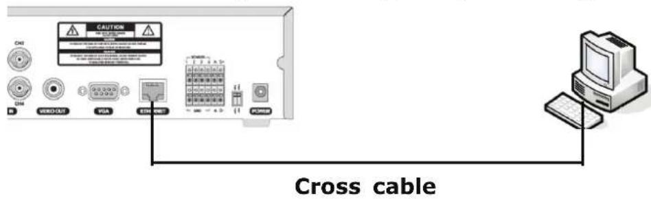
• LAN Connection - Using a cross cable, without a switching hub
Connect to the system directly, using a cross type network cable
• LAN Connection – Using a switching hub
Connect to the system, using a hub (Switching hub) and an Ethernet cable (10BASE-T/100BASE-TX CAT 5 LAN cable)
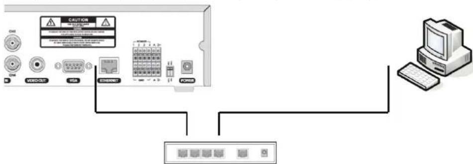
IP Router or HUB
- Internet (ADSL) Connection
Connect to the system, using a Router or ADSL modem and an Ethernet cable (10BASE-T/100BASE-TX CAT 5 LAN cable)
![graph TD A["USB"] --> B["TV USB"] B --> C["USB"] C --> D["GPIO"] D --> E["ADSL Modem"] E --> F["Internet"] F --> G["PC"] F --> H["PC"] F --> I["PC"] style A fill:#f9f,stroke:#333 style B fill:#ccf,stroke:#333 style C fill:#cfc,stroke:#333 style D fill:#fcc,stroke:#333 style E fill:#cff,stroke:#333 s…](/content/2026/05/1008175/images/91eca70dfcfc071071dc0f052f9a6337da173f848771574202e1c8a0ed4f9ed4.jpg)
IP Router or HUB
NOTICE
If you have an IP line with one IP address (whether it is dynamic IP or fixed IP), but you have more than one internet device (such as PC/PCs and a DVR); to use Router (It is different from a simple Network Hub); you must set up the Router to work with DVR; and you must use a network capable PC within the local Router network to do the setup. Whether you are using an existing Router or a new Router, you must go through the Port Forwarding portion of
1-3-3. Sensor and alarm connections
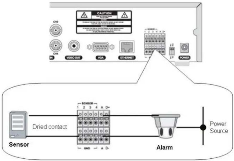
SENSOR INPUT: Connect two signal lines of sensor (infrared ray sensor, heat perception sensor, magnetic sensor) to the desired sensor number.
NOTICE
SENSOR inputs need dry contact only. Do not input any electric signal.
---: Not operational
N/O: Normally open type sensor. When magnetic sensor is closed, sensor sends a signal.
![graph LR A["Start"] --> B{Step} B --> C["End"]](/content/2026/05/1008175/images/57eddcd46fae6c75308de9b320d186c762814de07081c17e8469981f6d061275.jpg)
N/C: Normally closed type sensor. When magnetic sensor is opened, sensor sends a signal.
![graph LR A["Horizontal Line with Circles"] --> B["Vertical Line with Arrow"]](/content/2026/05/1008175/images/7aa0ecb5b53b6eb586afa11d687b93d35d34428112ad1a681d79da49afa5049f.jpg)
ALARM OUTPUT: Use Maximum current: 0.5A/125VAC, Maximum voltage:
1A/30VDC. When controlling lamp and AC operated equipment, control it using separate outside relay. During normal operation the control output contact is maintained at “Open” status, and during control output the output contact is changed to “Closed (short)” status.
2. Setting up the DVR
The following sections detail the initial setup of the DVR
2-1. Setup - Main Screen
When you press the SETUP button, the DVR will ask for a password. The default password is 1111, which can be entered by pressing the up button ( ) 4 times and then pressing the SEL button. We recommend you protect the system by assigning a new password immediately.
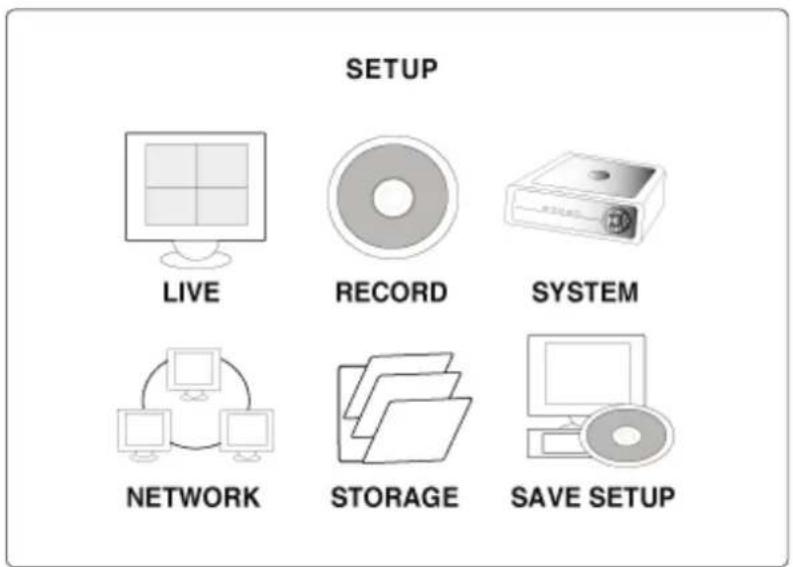
Figure 2.1.1. Setup menu screen
| SETUP | LIVE | OSD | |
| SEQUENCE | |||
| SEQ-DWEL TIME | |||
| EVENT BEEP | |||
| OSD CONTRAST | |||
| CHANNEL | DISPLAY, SEQ LIST, BRIGHTNESS, CONTRAST, HUE, SATURATION | ||
| VGA SCREEN MODE | |||
| ERROR ALARM | |||
| RECORD | RESOLUTION | ||
| CHANNEL Frame | rate, Quality, Recording, Motion zone,Motion sensitivity, Sensor type, Pre-Record,Post-Event Record, Alarm, Alarm Duration,Schedule | ||
| SYSTEM | DVR ID | ||
| DESCRIPTION | |||
| LOAD DEFAULT | |||
| ADMIN PASSWORD | |||
| NETWORK PASSWORD | |||
| DATE FORMAT | |||
| SET DATE & TIME | |||
| LANGUAGE | |||
| REMOTE CONTROL ID | |||
| DLS | |||
| NETWORK PORT | |||
| CLIENT ACCESS | |||
| BANDWIDTH SAVING | |||
| NE TWORK TYPE | |||
| DDNS | |||
| SEND E-MAIL | |||
| STORAGE | OVERWRITE | ||
| FORMAT | |||
| USB UPGRADE | |||
| SAVE SETUP TO A USB | |||
| LOAD SETUP FROM AUSB | |||
| VIDEO DELETE | |||
| DELETE VIDEO AFTER | |||
Table 2.1.1. Setup menu configuration
2-2. Setup - Live Mode
Table 2.2.1. Menu items in LIVE mode setup
| Item | Description |
| OSD Enable | e/disable on-screen-display. |
| SEQUENCE Enable | disable sequential display of video channels in full screen mode |
| SEQ-DWELL TIME | Dwell time for each cannel display in sequential display mode |
| EVENT BEEP | Enable/Disable internal beep alert sound. |
| OSD CONTRAST | Set the visibility level of the On Screen Display (OSD) |
| CHANNEL Select | the channel for applying the following settings. |
| DISPLAY Enable | disable disable display of the video channel in live display mode |
| SEQ LIST Enable | disable the specified channel to be included in sequential display mode. |
| BRIGHTNESS Change | the brightness value for the specified channel |
| CONTRAST Change | the contrast value for the specified channel |
| HUE Change | the hue value for the specified channel |
| SATURATION Change | the saturation value for the specified channel |
| VGA SCREEN MODE | Select VGA screen mode as either FULL or Normal. NOTE: If the mode is changed, the system will reboot. |
| ERROR ALARM | Enable/Disable alarm for video loss or HDD fail. |
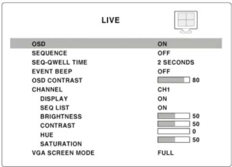
Figure 2.2.1. Live mode setup screen
2-3. Setup - Recording Mode
Table 2.3.1. Menu items in Recording mode setup
| Menu item | Description |
| RESOLUTION | Set resolution to either 704x480(NTSC)/704X576(PAL) or 352x240(NTSC)/352X288(PAL). |
| CHANNEL | Select the channel for applying the following settings. |
| FRAME RATE | Set the frame rate for the specified channel. The sum of the frame rate values from each channel cannot exceed maximum frame rates for a particular recording resolution. Typical values of the maximum frame rate for NTSC video are 120/100fps for 352x240(NTSC)/352X288(PAL) and 30/25 fps for 704x480(NTSC)/704X576(PAL) |
| QUALITY Select the recording quality for the specified channel to normal, high, or superior. | |
| RECORDING Assign the recording mode for each channel. Recording modes: Continuous, Motion, Sensor, Schedule, and Disable. | |
| MOTION ZONE | Select Full Zone or Partial Zone for motion sensing. If the Partial Zone is selected, screen will appear as shown in figure 3.3.2. |
| MOTION SENSITIVITY | Set the motion sensitivity for the specified channel. Control the motion sensitivity from 1 to 9. |
| SENSOR TYPE | Set the type of sensor for the specified channel from none, N/O (normal open), and N/C (normal closed). |
| PRE RECORD | Enable/disable pre-event recording. Pre-event recording time is 5 sec and only intra-frames are recorded for pre-event recording. |
| POST EVENT RECORD | Set post event recording time duration for the specified channel |
| ALARM Enable/disable alarm generation for the specified channel. | |
| ALARM DURATION | Set alarm time duration for the specified channel. |
| SCHEDULE Set recording schedule. If this menu item is selected, screen will appear as shown in figure 3.3.3. | |
| RECORD | |
| RESOLUTION | 352X240 |
| CHANNEL | CH1 |
| FRAME RATE | 1 FPS |
| QUALITY | HIGH |
| RECORDING | CONTINUOUS |
| MOTION ZONE | FULL ZONE |
| MOTION SENSITIVITY | 7 |
| SENSOR TYPE | - - - |
| PRE RECORD | ON |
| POST EVENT RECORD | 5 SECONDS |
| ALARM | OFF |
| ALARM DURATION | 5 SECONDS |
| SCHEDULE | |
Figure 2.3.1. Recording mode setup screen
2-3-1. Motion Zones
By selecting Partial Zone in the Motion Zone menu, users can set-up the motion sensing zones in the screen shown in figure 3.3.2. Move around each rectangular zone using 4 direction key buttons and press SEL button to include the rectangular region as part of the motion sensing zone. The rectangular blocks included as part of the motion zone are indicated by changing the color of the blocks.
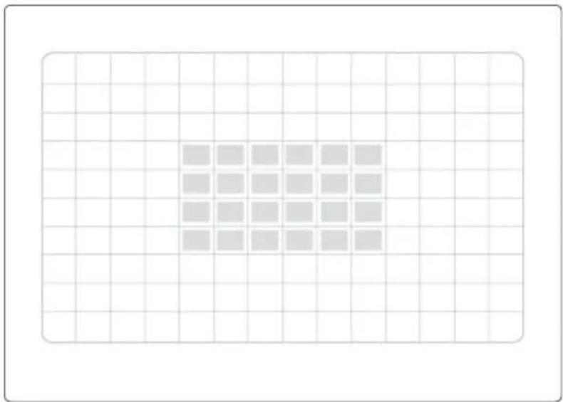
Figure 2.3.2. Motion Zone selection screen
2-3-2. Recording Schedules
To set up a recording schedule, select SCHEDULE in the RECORD menu.
Use the arrow buttons to navigate through the items and set the recording.
[ALL]: Selected recording mode using the SEL button is applied to the entire time zone and all channels.
[SUN to SAT]: Selected recording mode using the SEL button is applied to the entire time zone for the specified channel.
[Vertical Bar “ | ”]: Selected recording mode using the SEL button is applied to the entire channel for the selected time zone. Each vertical bar “ I “ corresponds to one hour.
[- Individual Block of Time]: Selected recording mode using the SEL button is applied to the selected 1-hour increment for the selected channel.
[SEL]: The recording mode can be selected using the SEL button.
[COPY FROM to COPY TO]: Setup values of recording mode for the selected channel can be copied for another channel setup.
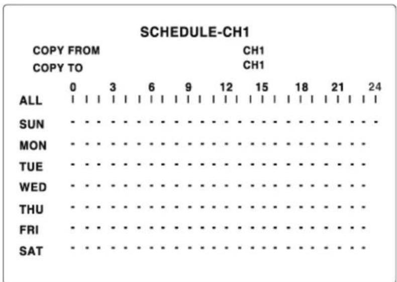
Figure 2.3.3. Schedule recording setup screen
2-4. System
Table 2.4.1. Menu items in System Setup screen
| Item | Description |
| DVR ID The name of the system. Press the SEL button and move through the position for each alphanumeric character by pressing the LEFT and RIGHT buttons. UP/DOWN buttons are used to change character for each location. | |
| DESCRIPTION | Press SEL to see system information. |
| LOAD DEFAULT | Choose OFF or ON. If selecting ON, press the SEL button to load defaults. |
| ADMIN PASSWORD | Set the password for the administrator. Once this menu is selected, the DVR will ask you current password and new password. Follow the procedure provided by the DVR. The password numbers (1,2,3,4) can be input by using direction keys.The default password is 1111. |
| NETWORK PASSWORD | Set the password of network client. Once this menu is selected, the DVR will ask you current password and new password. The DVR will guide you through the entire process of setting up the user password. The password numbers (1,2,3,4) can be input by using direction keys. The default password is 1111. |
| DATE FORMAT | Select the preferred date and time display. |
| SET DATE & TIME | Set the present date and time. If DLS function is ON, user can not enter into this menu and change date and time. |
| LANGUAGE Select a language. | |
| REMOTE CONTROLLER ID | Select an ID of remote controller.1. Select ID from 1 to 9.2. Press the same number as ID set in DVR on the remote controller3. Then  on will be displayed on Live screen of DVR that responds to the remote controller. on will be displayed on Live screen of DVR that responds to the remote controller. |
| DLS User | can set to ON or OFF for DLS (Daylight Saving) by using LEFT or RIGHT button. After selecting ON, move the cursor to BEGIN (MM/DD/HH) field and press the SELECT button to set the start time of DLS, Then move to END(MM/DD/HH) field to set the stop time of DLS by using UP or DOWN button.CAUTION:-DLS can’t start from 23:00-DLS can’t be applied, if the date of BEGIN and END is same. |
| SYSTEM | |
| DVR ID | DVR |
| DESCRIPTION | |
| LOAD DEFAULT | |
| ADMIN PASSWORD | |
| DATE FORMAT | |
| SET DATE&TIME | YYYY/MM/DD |
| PTZ CONTROL | |
| LANGUAGE | ENGLISH |
| REMOTE CONTROLLER ID | 0 |
| DLS | ON |
| BEGIN | 2/1 OH |
| END | 9/1 OH |
Figure 2.4.1. System setup screen

Figure 2.4.2. DVR ID setup screen

Figure 2.4.3. DVR information display screen
DATE & TIME
2006/03/13 17:46:20
Figure 2.4.4. Date & Time setup screen.
2-5. Network
Set up your network parameters on the Network Setup screen.
Table 2.5.1. Menu items in Network Setup screen
| Item | Description |
| PORT Port number (Default: 5445) | |
| CLIENT ACCESS | Enable/Disable remote access through client software. |
| BANDWIDTH SAVING | Enable/Disable only key frame transmission. “ON” mode is favorable for use of low network bandwidth. Mostly, set “OFF” for normal use. |
| NETWORK TYPE | Set the type of network connection. Options are: LAN, DHCP, ADSLNote. Other parts of the Network Setup screen will change depending on what network type you select. |
| DHCP Set to use DHCP (If this is selected, DVR will automatically receive IP varying from time to time from network.) | |
| ADSL (PPPoE) ID: Registered ID is necessary for ADSL connection.Password: Registered password is necessary for ADSL connection. | |
| LAN IP: Register IP address that is assigned for DVR.Gateway: Register Gateway that is assigned for DVR.Subnet Mask: Register Subnet Mask that is assigned for DVR. | |
| DDNS Enable/disable using domain name address through DDNS server.“ON” mode, DDNS server name appears for domain registration.The DDNS sever name is vitekddns.comCAUTION: Do not change this sever name. If this is | |
changed, the DDNS service cannot be used.
| NETWORK | |
| PORT | 5445 |
| CLIENT ACCESS | ON |
| BANDWIDTH SAVING | ON |
| NETWORK TYPE | LAN |
| IP | 172. 16. 1. 52 |
| GATEWAY | O.O. O. O. |
| SUBNET MASK | 255. 255. 0. 0 |
| DNS SERVER IP | 172. 16. 1. 220 |
| DDNS | OFF |
| SEND E-MAIL | OFF |
Figure 2.5.1. Network setup screen
2-5-1. Ports
When you connect one or more DVRs to a local network through a Router, each DVR must have a unique TCP port number to access it from outside the LAN. In this type of setup, the Router must be configured for port forwarding so that each DVR can be accessed from outside the network. Port Forwarding on the Router is needed to forward the connection to the appropriate DVR.
Note: This port number is listed next to the Port Network Setup screen. If you plan to access the DVR units only from within the same LAN, the TCP port does not need to be changed.
Network Access Beyond Router
In order to access beyond a Router (Firewall), user must open 1 TCP port for Command level, Live channels, and Storage channels. If this port is not open properly, user will not be able to access the DVR beyond a router.
Example: If the DVR set's port number is 5445, TCP port 5445 must be open on the Router.
2-5-2. Network types
2-5-2-1. LAN
- Fixed IP assigned by a Network Administrator. (Contact your network administrator)
- Router/Modem: In a local network environment, an IP address is assigned to the DVR by either a Router or Modem. If an IP address is provided by a router, either the DMZ function or Port Forwarding must be enabled (on the router) to access the DVR from outside of the LAN.
- An IP address must be entered for the DVR along with the subnet mask and Gateway (gateway is usually the IP address of the router). The DNS Server IP can be the same address as the gateway unless there is one provided by an ISP.
| NETWORK | |
| PORT | 5445 |
| CLIENT ACCESS | ON |
| BANDWIDTH SAVING | ON |
| NETWORK TYPE | LAN |
| IP | 172. 16. 1. 52 |
| GATEWAY | O.O. O. O. |
| SUBNET MASK | 255. 255. 0. 0 |
| DNS SERVER IP | 172. 16. 1. 220 |
| DDNS | OFF |
| SEND E-MAIL | OFF |
Figure 2.5.2. Network setup screen - LAN
Table 2.5.2. LAN
| Item | Description |
| IP The fixed IP address of the DVR unit | |
| GATEWAY The IP address of the Gateway | |
| SUBNET MASK | The subnet mask for the LAN |
| DNS The address for the DNS server | |
2-5-2-2. DHCP
In a DHCP environment, the IP Address is automatically assigned by a DHCP server. With DHCP enabled, the DVR will automatically ‘request’ an IP Address from the DHCP Server. This configuration is useful when the
network settings (Server/Router) are not accessible, when the DVR is directly connected to the internet without the use of a Router or Server, or when the connection uses a dynamic IP method (not Fixed or Static).
| NETWORK | |
| PORT | 5445 |
| CLIENT ACCESS | ON |
| BANDWIDTH SAVING | ON |
| NETWORK TYPE | DHCP |
| DDNS | ON |
| DDNS SERVER NAME | NS.STAND |
| SEND E-MAIL | OFF |
Figure 2.5.3. Network setup screen - DHCP
2-5-2-3. ADSL (PPPOE)
The ADSL setting is used when the PPPoE protocol (ISP authentication) is required by the ISP and the DVR is directly connected to the internet (without a Server or Router).
A User Name (ID) and Password issued by the ISP is required. If you are using a Router or you have a static IP address from your ISP and you are using a modem/Bridge, use the DHCP or LAN option.
| NETWORK | |
| PORT | 5445 |
| CLIENT ACCESS | ON |
| BANDWIDTH SAVING | ON |
| NETWORK TYPE | ADSL |
| ID | |
| PASSWORD | |
| DDNS | ON |
| DDNS SERVER NAME | NS.STAND... |
| SEND E-MAIL | OFF |
Figure 2.5.4. Network setup screen - ADSL
Table 2.5.3. ADSL
| Item | Description |
| ID The user ID for ADSL connection | |
| PASSWORD The password for ADSL connection | |
2-6. Storage
User can set recording mode on the hard disk drive (HDD) or initiate formatting of the hard disk drive.
Table 2.6.1. Storage setup
| Item | Description |
| OVERWRITE Overwrite existing material when hard disk drive is full | |
| FORMAT Format hard disk drive | |
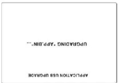
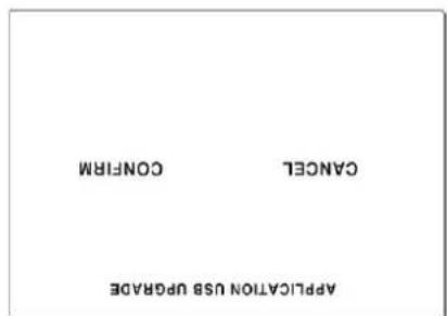
| USB UPGRADE | The firmware of DVR can be upgraded through the USB port.In order to upgrade, the upgrade firmware must first be downloaded and copied onto the USB device. Create a new folder on the USB memory stick and copy the upgrade firmware “app.bin” into the folder.(This folder name should be “upgrade”.)After the upgrade firmware is copied onto the USB memory stick, perform the following;1. Connect USB memory stick into the USB port.2. Go to the STORAGE>USB UPGRADE.3. Select “CONFIRM” and the upgrading will start automatically.4. After the upgrade is complete, the DVR will reboot automatically. |
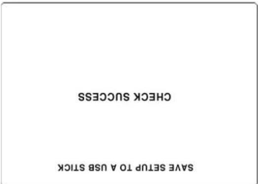
| SAVE SETUP TO USB Device | User can save the current configuration of DVR to the USB memory stick. Insert the USB stick into the front panel connection and press SEL to start the saving process |
| LOAD SETUP FROM A USB Device | User can upload the configuration of DVR to another DVR using the USBMemory stick. Insert the USB stick into the front panel and press SEL to start the loading process.After upgrade is complete, the DVR will reboot automatically and setup value will be applied. |
| VIDEO DELETE | Enable/disable recording limit. |
| DELETE VIDEO AFTER | Set the limit of days to be recorded to the hard disk drive from 1 to 60 days. |
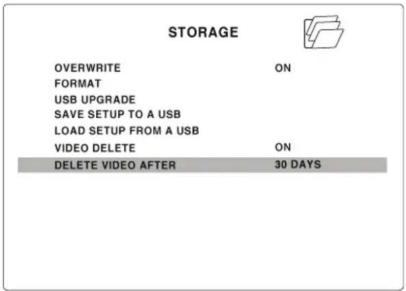
Figure 2.6.1. Storage setup screen
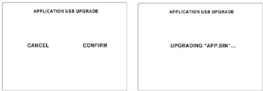

Figure 2.6.2. Storage setup -USB UPGRADE
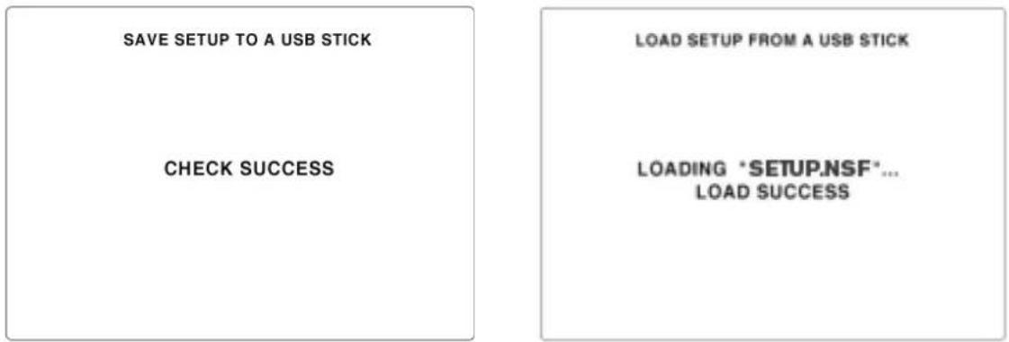
Figure 2.6.3. Storage setup – save & load setup from a usb device
3. LIVE & SEARCH
3-1. Live Window
In the Live window, video inputs from the cameras are displayed on the configuration of the live setup. Figure 4.1.1 shows the layout of the live screen. Various indicators showing the status of the DVR are shown as OSD symbols. Refer to Table 4.1.1 for the meaning of the indicators.
| CH1 | C | S | CH2 | |
| CH3 | M | C | CH4 | |
| 2007/05/05 15:30:30 | 90% | |||
Figure 3.1.1. Live display screen
Table 3.1.1. Indicator ICONS in Live window
| Indicator | Description |
| × | Continuous recording in progress |
| × | Manual recording in progress |
| × | Sensor alarm recording in progress |
| × | Motion alarm recording in progress |
| × | Indicates no alarm event |
| × | Alarm indicator. When there is an alarm (sensor alarm or motion alarm) on a video channel, this icon will be highlighted in bright red. |
| × | Indicates that alarm output is activated. |
| × | Indicates that a network client is connected to the DVR. |
| × | Indicates that sequencing mode is enabled. |
| × | Indicates that the HDD recording is being recycled |
 | Indicates the percentage of recorded data onto HDD |

Table 3.1.2. Button functions of remote controller in Live window
| Button | Description |
 | Select channel to be displayed in full screen mode. |
 | Switch between full screen and quad display mode. |
| SEQ | Press to start auto sequencing of the screen in full screen mode. (Toggle) |
| RECORD Press to start and stop manual recording. | |
| SEARCH | Press to go to the search menu.Event search /Time line search /Log /Archive search |
| ARCH | Press to capture a still image. The still image will be stored onto the hard drive. It can be transferred to the USB device. |
| SETUP Press to launch SETUP menu. | |
| ESC | Press for temporal storage of the changed value or to return to the previous menu screen. |
3-2. SEARCH window
Press SEARCH in live mode to enter the Search screen.
When you press the Search button, the DVR will ask for a password as in Figure 3-2-1.
Enter the password using the arrow controls.
There will be 7 different search functions such as TIMELINE, EVENT, GO TO FIRST TIME, GO TO LAST TIME, GO TO SPECIFIC TIME, LOG, and ARCHIVE displayed on the screen.
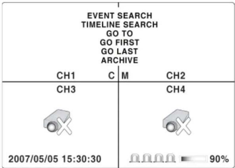
Figure 3.2.1. Search window
3-2-1. EVENT Search
The Event Search window is used to find stored video. Three categories of search filters can be applied: DATE, CHANNEL and TYPE. Press SEL to select a value and move down to the next category. Use the UP arrow button to move up to the categories you have previously entered. The ESC button will return the user to the previous screen.
- Select the date of the video to begin searching. Use the LEFT, RIGHT, UP, and DOWN buttons to navigate through the days.
- Once you have selected the date, press SEL to move to the CHANNEL selector.
- Use LEFT and RIGHT buttons to change the channel selection from ALL to any of the available channels.
- Once you have selected the channel, press SEL to move to the TYPE selector.
- Use the LEFT and RIGHT buttons to change the type of recording to ALL, MOTION, SENSOR, MANUAL, or CONTINUOUS.
- Once you have selected the type of recording to search for, press SEL to produce a list of events/instances that fit your search criteria.
- Use the UP and DOWN buttons to scroll through the on-screen listings.
- Use the LEFT and RIGHT buttons to display a list of events that happened previous to or after the current selection.
- Once the desired event has been selected, press SEL to start playing back the selected video.
- Press the BACKUP button to launch the archiving function in playback mode.

| LIST | |
| 2006/12/12 | (1/2) |
| <15:05:24> | CH1:MANUAL |
| <15:05:27> | CH2:MANUAL |
| <15:05:28> | CH3:MANUAL |
| <15:06:28> | CH4:MANUAL |
| <15:07:28> | CH1:CONTINUOUS |
| <15:07:38> | CH2:CONTINUOUS |
| <15:08:38> | CH3:CONTINUOUS |
| <15:18:38> | CH4:CONTINUOUS |
| <16:05:24> | CH1:MANUAL |
| <16:05:27> | CH2:MANUAL |
| <16:05:28> | CH3:MANUAL |
| <16:06:28> | CH4:MANUAL |
Figure 3.2.2. Event search screen
3-2-2. TIME LINE Search
The TIME-LINE search window is used to find the stored video by using the time line bar.
- Select the date of the video to begin searching by using the LEFT, RIGHT, UP and DOWN buttons to navigate through the days.
- Once you have selected the date, press the SEL button to move to the time line search window.
- Use LEFT / F/ADV or RIGHT/ F/REW buttons to select a time zone on the 24 hour time table.
Note: The recording mode is indicated on the screen as below.
C: Continuous-Green
M: Motion-Yellow
S: Sensor-Red
R: Manual -Purple
- Once you have selected the time zone, press the SEL button to move to the 60 minute time table.
- Select ALL or a specific channel to search by using the UP and DOWN
arrow buttons.
- Once you select the channel, use the LEFT / F/ADV or RIGHT/ F/REW arrow buttons to move the time line select bar (blue) to the point where you wish to start playing the video clip.
- Press the SEL button to playback the recorded video.


Figure 3.2.4. Time line search screen
3-2-3. GO TO
You can search for specified data by setting the time and date in this menu. Use the LEFT or RIGHT button to move from left to right in this menu. Use the UP or DOWN button to set the date and time.

Figure 3.2.5. GO TO search screen
3-2-4. GO FIRST
You can access the first or earliest data which has been recorded into the HDD disk by pressing this menu.
3-2-5. GO LAST
You can access the last or most recent data which has been recorded into the HDD disk by pressing this menu.
3-2-6. LOG List
User can see the system log list by selecting this item.
| CH1 C | LIST |
| 2006/12/12 (1/2) | |
| <15:05:24> SYSTEM START | |
| <15:05:27> ENTER SETUP | |
| <15:05:28> EXIT SETUP | |
| <15:06:28> ENTER SETUP | |
| <15:07:28> SYSTEM START | |
| <15:07:38> SYSTEM START | |
| <15:08:38> ENTER SETUP | |
| <15:18:38> EXIT SETUP | |
| <16:05:24> ENTER SETUP | |
| <16:05:27> SYSTEM START | |
| <16:05:28> ENTER SETUP | |
| <16:06:28> SYSTEM START |
Figure 3.2.6. Log list screen
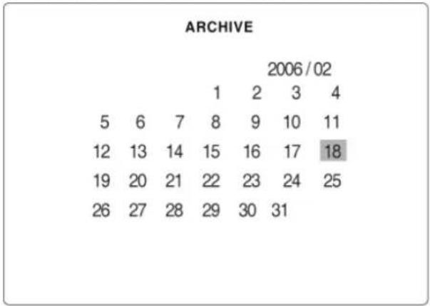
3-2-7. ARCHIVE Search
The ARCHIVE SEARCH window is used to find the stored video.
- Select the date on the calendar to begin searching by using the LEFT or RIGHT button.
- Once you have selected the date, press the SEL button to move to the list of recorded data.
- Use the UP or DOWN button to scroll through the onscreen listings.
- Once the desired event has been selected, press the SEL button to see the selected video in paused mode.
- Press the ARCH button to archive the video into USB memory stick.
| CH1 C | LIST |
| 2006/12/12 (1/2) | |
| <15:05:24> LIVE JPEG |
Figure 3.2.7. Archive search screen
3-3. Playback mode
During the playback of a recorded event, the mode changes from SEARCH to PLAY. While in PLAY mode, you may return to the SEARCH LIST by pressing the ESC button. Playback will start in quad mode with channel 1 highlighted by default. If audio is enabled, it will only play from the highlighted channel.
| CH1 | C | S | CH2 | |
| CH3 | M | C | CH4 | |
| 2007/05/05 15:30:30 | ||||
Figure 3.4.1. Playback mode screen
Table 3.4.1. Button functions of remote controller in Playback mode
| Button | Description |
| ESC Return to the previous menu screen, search list, or exit menu | |
| ◀◀REW | Press to rewind the footage at 1x, 2x, and 4x speeds. Reverse playback speed is shown as -1x (normal), -2x (2 times normal), and -4x (4 times normal) at the bottom right of the screen. |
| ●●◀F/REW | Jump/Step backward. – The playback position moves 60 seconds backward. |
| PLAY/PAUSE | Press to play or pause recorded video. |
| F/ADV ▶●● | Jump/Step forward -Playback position moves 60 seconds forward. |
| FF ▶▶ | Press to fast forward the footage at 1x, 2x, and 4x speeds. Playback speed is indicated as +1X, +2X, and +4X for normal, twice, and 4 times of the regular speed at the bottom right of the screen. |
 | UP: 1CH, RIGHT: 2CH, DOWN: 3CH, and LEFT: 4CH to be highlightedUP: NO. 1, RIGHT: NO. 2, DOWN: NO. 3, and LEFT: NO. 4CH to input password |
| ARCH Press the ARCH button to archive the video into HDD. | |
4. Archiving and Backup
To backup a still image or video to a USB storage device, user must firstly archive a still image or video to the hard drive.
4-1. Archiving Still images or Video
Still images can be captured and archived into the hard drive in live mode or while playing back.
- In Live Mode, press ARCH button to capture and archive the still image. Once you press the ARCH button, the screen will be displayed as shown in Figure 5.1.1.

Figure 4.1.1. Archive screen in Live mode
- In Playback Mode, the DVR will ask whether to store still image or video. The user may select either still image or video, and it will store onto the HDD. User can find the list of archived data in the ARCHIVE search menu.

Figure 4.1.2. Archive screen in Playback mode
4-2. Backup still images or videos on USB memory stick
- To begin transferring stored image or video into a USB memory stick, connect a USB memory stick to the front panel drive.
- Press the SEARCH button to bring up the ARCHIVE search screen which will allow you to specify a date and time to search for stored images or video.


Figure 4.2.1. Archive search screen
- Press the SEL button to retrieve lists of archived images or video.
- Select and display one of the files on the screen in the archived list by using the UP or DOWN button.
- Then press the ARCH button to transfer the data onto the USB memory stick.
- If there is not enough space on the USB memory stick, the DVR will popup a message that there is no space in the USB memory stick.
4-3. Playing backup file
- Playback of AVI format: AVI format video can be played back by Windows Media Player™ or other media player that is compatible with AVI format video.
When the PC doesn't have the proper H.264 CODEC, the media players can not playback the AVI format video. In this case, you must
- DVR (Exclusive video format): DVR format video can be played back by the DVR player (exclusive video viewer). That DVR player software will automatically copy onto the USB thumb drive along with the video clip.
Three files are copied on USB thumb drive
- DVR file: Exclusive format video file.
- SMI file: Title file of date and time.
- PLAYER: Exclusive video viewer.


5. Network access using the Network Viewer
The DVR provides a live remote monitoring feature. Remote monitoring requires installation of the network viewer on your PC.
NOTICE
In a high bandwidth network, a maximum of four users can access one DVR simultaneously. In a low bandwidth network it is recommended that only one user access the DVR at a time.
5-1. PC requirements
• CPU: Intel Pentium IV 1.2Ghz or higher
• Memory: 256MB (512MB or higher is recommended.)
• VGA memory: 16MB (64MB or higher is recommended.)
• Resolution: 1024x768
• O/S: Windows 2000, XP Professional, XP home
- Direct X: DirectX 8.1 or higher
5-2. Installing the network viewer
-
Insert the provided CD in the CD drive and double-click "UMSClient(XXXX).exe"
-
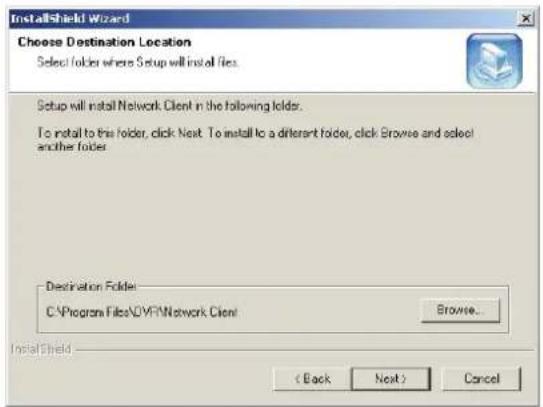
Select a destination folder and click 3. Select the type and click "Next". "Next".

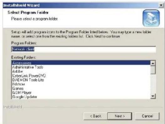
- Select the program folder and click 5. The setup status screen. "Next".

- Once installation is complete, a "UMS Client" Network Client icon will be on the desktop.

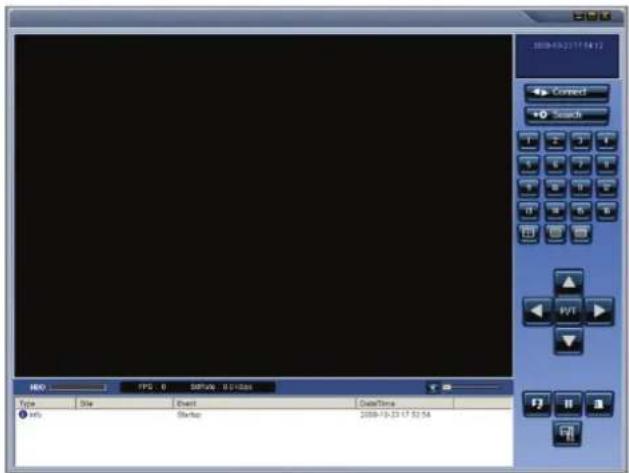
5-3. Live monitoring mode and functions.
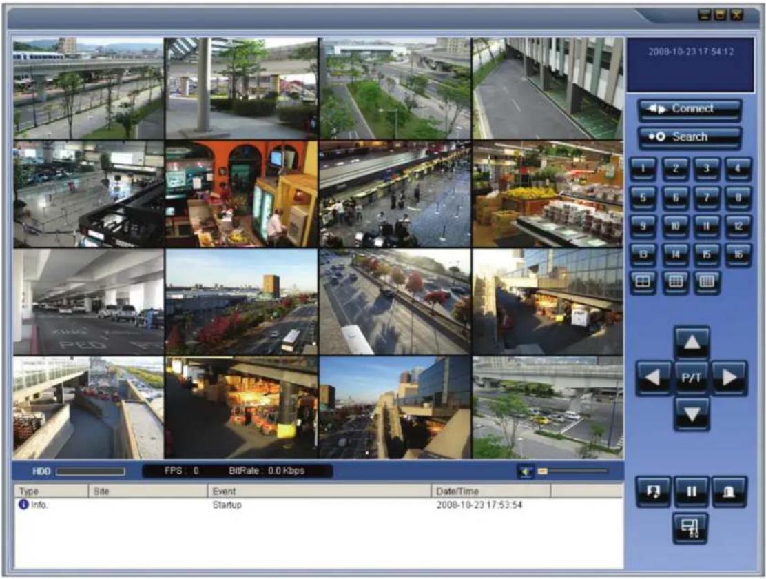
| Button | Function | Description |
 | DATE & TIME Displays | the current date and time. |
 | CONNECT/DISCONNECT | Connect/disconnect network connection.. |
 | SEARCH Switches the live mode to search mode. | |
 | DISPLAY MODE Select a channel and screen display mode. | |
 | PAN/TILT/ZOOM/FOCUS | Control the PAN/TILT/ZOOM/FOCUS features on the remote camera. |
 | CAPTURE Capture a still image from live screen. | |
 | PLAY/PAUSE Play/pause live video. | |
 | ALARM The ON/OFF button of the alarm output of the DVR. When an alarm of the DVR is output, this button becomes Red. | |
 | SETUP Display the setup screen of the network viewer. | |
 | HDD USAGE DVR HDD storage Indicator. | |
 | NETWORK BANDWIDTH Shows the transferred frames and network bandwidth. | |
 | LOG WINDOW | |
Operations of the display mode of the main screen
- Single channel display - Click the one of the channel buttons or double-click the channel screen.

• QUAD/Split Screen display - Click a Split Screen button to view
multiple cameras simultaneously.
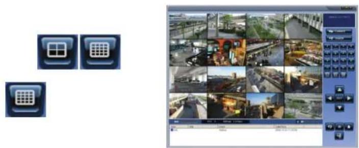
- Full screen display - Click the maximize button to display only screen and hidden the operation panel.

Image capture of live screen
Still-image of live screen can be captured and saved as BMP or JPEG file.
- Click the channel to be captured. Then the channel screen is surrounded with a red line.
- Click the CAPTURE button. Then the IMAGE CAPTURE dialog is displayed.
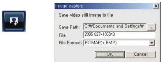
- Set the conditions and click the OK button. Then the still-image is saved.
5-4. Bi directional audio
The UMS Client allows for bi directional audio between the client and a DVR unit.
5-5. Remote search mode and functions
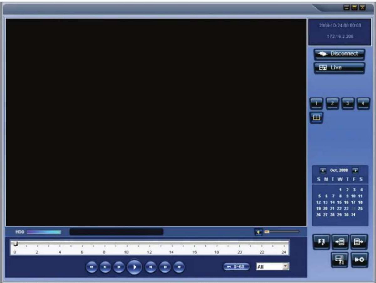
| Button | Function | Description |
 | DATE & TIME | Displays the recording time of the data selected on the time bar at the bottom of the main user interface. |
 | DISCONNECT | Disconnect network connection. |
 | LIVE Switches | the search mode to live mode. |
 | CAPTURE | Capture a still image from live screen. |
 | MARK IN Set the start time for video backup. | |
 | MARK OUT | Set the ending time for video backup. |
 | BACKUP Backup | the selected recorded video as AVI format. |
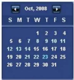
 | SEARCHCALENDAR | The calendar shows dates with recorded video in a light blue and the selected date in dark blue. |
 | TIMELINE BAR | The timeline shows recorded data in dark blue on the bar. |
 | PLAYBACKBUTTON | The playback buttons. |
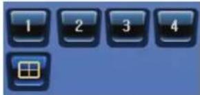 | DISPLAYMODE | Select a channel and screen display mode. |
Searching and playing video from the remote DVR
Video recorded on the remote DVR or Video recorded on the PC can be searched and played back.
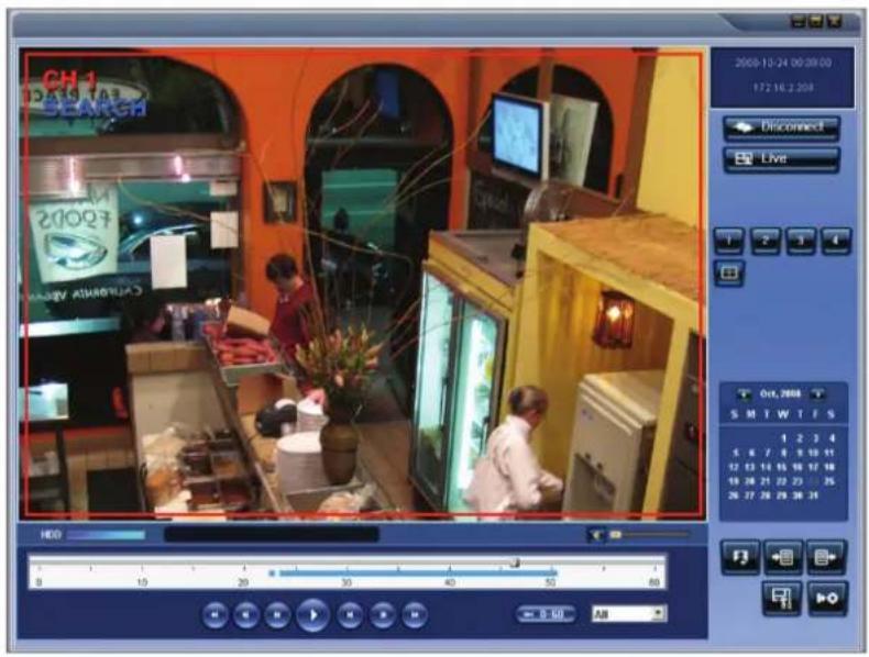
- Connect the network to the remote DVR and press SEARCH button. Then the mode is changed from the live mode to the search mode.

- Searching the video recorded on the remote DVR: Connect the network to the DVR..
-
Searching the video recorded on a PC: Do not connect the network to the DVR.
-
Select the date to search the video.
- Drag the slid on the time scale and drop it between 0 to 24.

- Press the PLAY button. Then the video recorded on the remote DVR is played back.
Backup of video on the remote DVR
Video recorded on the remote DVR can be backed up on the PC HDD as AVI format.
- Connect the network to the remote DVR and play the video recorded in the remote DVR.
- Drag the slide on the time scale and drop to the start time for video backup and press the MARK IN button.

- Drag the slid on the time scale and drop to the end time for video backup and press the MARK OUT button. Then the marked time is displayed in dark green.
![graph LR A["0"] --> B["2"] B --> C["4"] C --> D["→"] D --> E["0"] E --> F["2"] F --> G["4"] G --> H["→"]](/content/2026/05/1008175/images/66fc4497f9a18cfe447b5350da2bcca43bb6b88a52480ac8b81528eaa619ba93.jpg)
- AVI Backup dialog is displayed. Click the OK button. Then the marked video is backed up.

- Start time / Stop time: Backup time can be changed.
- File path: Shows the folder that the backup file is recorded.
- Channel: Shows backup channel..
5-6. PC System configuration
Click the SETUP button. Then the Setup dialog is displayed.

Setting General
Set security options, save path, and Automatic reconnection.

- Security Option: Set a password for security options. When you access any of the selected functions, you will need to enter the password.
- Save Path: Specify the location to record for backup and still image capture.
- Automatic reconnection: If a user selects this function, the client S/W will automatically try to connect to the previously connected IP address if the network connection is lost.
- Display network statistics: If a user selects this function, the client S/W will display network status, Bit rate and Frame rate.
● Time Format: Change the time format mode on the Client software display.
Setting Site
The remote DVRs can be added, modified, and removed.

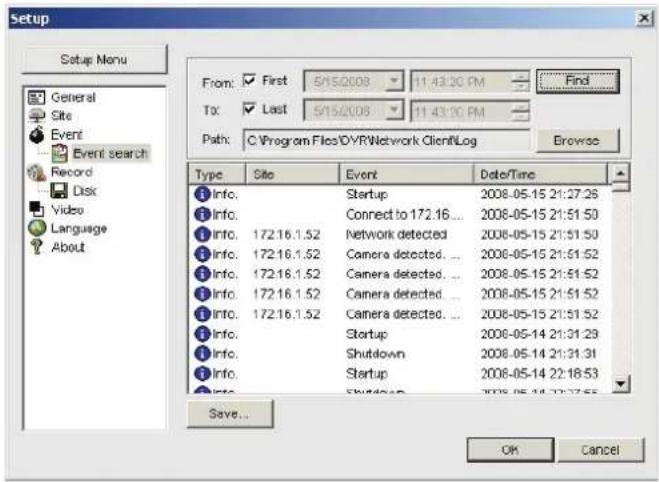
Setting Event
Set the record path and the size of local disk space for the log files.
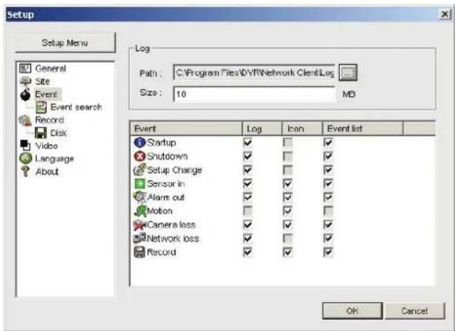
- LOG - Select to save event log into 'log file'.
- ICON - Select to display the event on live video.
- EVENT LIST – Select to show the event in the ‘Event List’ window of live mode.
Search and check the recorded log data.
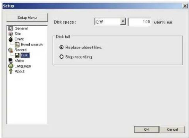
Setting Record
Set the recording conditions and select channels to record.

Select the local disk to use and the amount of disk space you want to allow the program to use for recording.
Setting Video
Set the video screen.

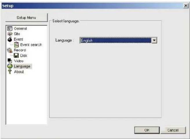
Setting Language
Select the language of the network client viewer.
6. Network - By a web-browser viewer
The DVR provides a live remote monitoring feature by web-browser viewer.
- Check the IP address of the DVR from SETUP>SYSTEM>DESCRIPTION>IP ADDRESS.


- Input the IP address or Domain name address that you pre-registered on www.vitekddns1.com in the address field and press "Go".

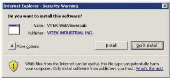
- Click the bar at the top of the web browser to install the WebViewer.
This website wants to install the following add-on: VITEK-WebViewer.cab' from 'VITEK INDUSTRIAL INC.' If you trust the website and the add-on and want to install it, click here...
- Click "Install" to download ActiveX control.
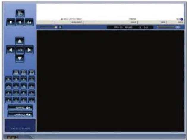
- Web Browser Viewer is displayed as below.

- Click the CONNECT button on the Left upper corner of the web-viewer. Then “Connect” dialog is displayed. Enter IP address (or Domain name address that you pre-registered on http://www.vitekddns1.com), Port number and Password and click “Connect”
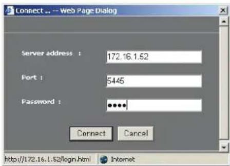
- Server address: Input IP address of the DVR from SETUP>SYSTEM>DESCRIPTION>IP ADDRESS or Domain name address that you pre-registered on http://www.vitekddns1.com
- Port: Input Port number (The number sets on SETUP>NETWORK>PORT)
-
Password: Input Password (The number sets on SETUP>SYSTEM>NETWORK PASSWORD
-
Then the cameras connected to the DVR are displayed on the screen.

APPENDIX: How to connect to a network
A. How to set the IP address of the DVR and open the TCP port of the router?
The port forwarding is dependant on the brand and model of the router. The port forwarding is required to allow access to the DVR beyond a router.
- Connect network cable between DVR and Router or ADSL modem.
![graph TD A["IP Router or HUB"] --> B["ADSL Modem"] B --> C["Internet"] C --> D["Computer"] style A fill:#f9f,stroke:#333 style B fill:#ccf,stroke:#333 style C fill:#cfc,stroke:#333 style D fill:#fcc,stroke:#333](/content/2026/05/1008175/images/146e5290acd0ce210cc8f86c214ed5f5e6068414d14bcb1e167ef4038cafcb29.jpg)
-
Default network settings on DVR are
-
Port: 5445
- WEB Port : 80
-
Network : DHCP
-
From a PC connected to the same Router, find the IP address, Gateway, and Subnet mask by IPCONFIG command in command prompt.
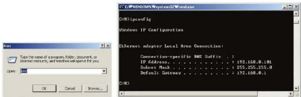
- If IP is begins with 192.168.x.xxx., you should change IP address, Subnet, Gateway on the DVR. Go to SETUP>NETWORK>LAN of the DVR and change the IP settings to be like IP: 192.168.XXX.XXX and Gateway: 192.168.XXX.XXX. (Refer to the user's manual of Router.)

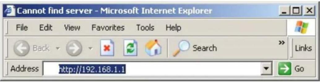
- Open your web browser. Enter the router IP address in the address bar (The router IP address is unique to the brand and model.), click GO.
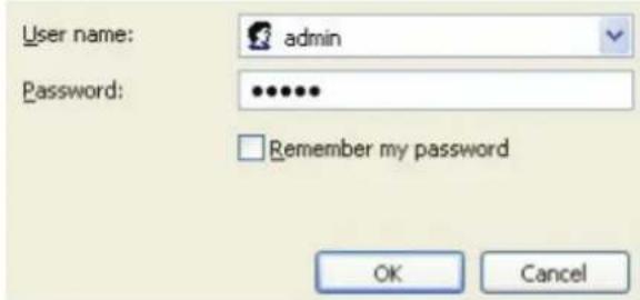
- Enter the user name and password (admin is default) and press the OK button.
- Select the Port Range Forwarding tab.
| Setup | Wireless | Security | Access Restrictions | Applications & Gaming |
| Port Range Forward | 1 | DMZ | ||

- Enter each field.
i. Application: Enter a description of the DVR (Example: store1)
ii. Start: Enter the first number of the port you need to port forward (Example: 5445)
iii. End: Enter the last number of the port you need to port forward (Example: 5445)
iv. Protocol: Select Both.
v. IP address: Enter the IP address of the DVR on SETUP>NETWORK>LAN>IP ADDRESS.
vi. Enable: Check the enable box.
- Select the Save settings button located at the bottom of the window. Then Port forwarding is finished.

You can learn how to port forward many kinds of Routers from the below site. http://www.portforward.com/english/routers/port_forwarding/routerindex.htm
B. How to access the DVR from Remote PC?
• LAN Connection - Using a switching hub
Connect to the system, using a hub (Switching hub) and an Ethernet cable (10BASE-T/100BASE-TX CAT 5 LAN cable)
![graph TD A["服务器"] --> B["电脑"] C["服务器"] --> D["电脑"] E["服务器"] --> F["电脑"] G["服务器"] --> H["电脑"] I["服务器"] --> J["电脑"] K["服务器"] --> L["电脑"] M["服务器"] --> N["电脑"] O["服务器"] --> P["电脑"] Q["服务器"] --> R["电脑"] S["服务器"] --> T["电脑"] U["服务器"] --> V["电脑"] W["服务器"] --> X["电脑"] Y["服务器"] --> Z["电脑"]](/content/2026/05/1008175/images/3b572febdd625567a74dd2047427d6ef16cda040f1b227236b7f81ea9be8aaca.jpg)
IP Router or HUB
- Run the pre-install the network client software on the supplied CD. (Refer to Chapter 6. Network access using the Exclusive network viewer)
- Check the IP address from SETUP>SYSTEM>DESCRIPTION of DVR.
- Run the network client software and click CONNECT button.

- Input IP address, Port No., and Password on the connect window. And click OK.

- Internet (ADSL) Connection using DDNS
Connect to the system, using a Router or ADSL modem and an Ethernet cable (10BASE-T/100BASE-TX CAT 5 LAN cable)
![graph TD A["IP Router or HUB"] --> B["ADSL Modem"] B --> C["Internet"] A --> D["USB"] D --> E["CAUTION"] E --> F["Control Panel"] F --> G["Computer"] G --> H["Computer"] H --> I["Internet"]](/content/2026/05/1008175/images/ba151716966c2f5684eae9461802c41de2fe8465f36437c8be09223c4da47622.jpg)
- Go to SETUP>NETWORK. Set NETWORK TYPE as DHCP and DDNS SERVER as ON. And make sure that DDNS SERVER NAME is vitekddns1.com
- Go to Setup menu of Router and open TCP port 5445 using Port Forwarding. (Refer to A. How to set IP address of the DVR and open TCP port of the router?)
- Confirm the Mac address and Serial No. from the label of the rear panel of the DVR.
- Open the web browser and log on http://www.vitekddns1.com

- MAC Address: Input the Mac address (EX. 0002690XXXXX) without a space.
- Serial Number: Input the Serial No. (EX. 43000700XXX.) without a space.
- Domain Name: Input Domain Name for your DVR system (Note. Input only Domain Name and never input “vitekddns1.com”.)
- Click the DUPLICATION CHECK button to see if the domain name is available.
- If you see the screen "You can use the Domain name you entered" then click RETURN and click the REGISTER button to complete the registration.
- Run the pre-install the network client software on the supplied CD. (Refer to Chapter 6. Network access using the Exclusive network viewer)

- Click button and add the DVR as necessary.
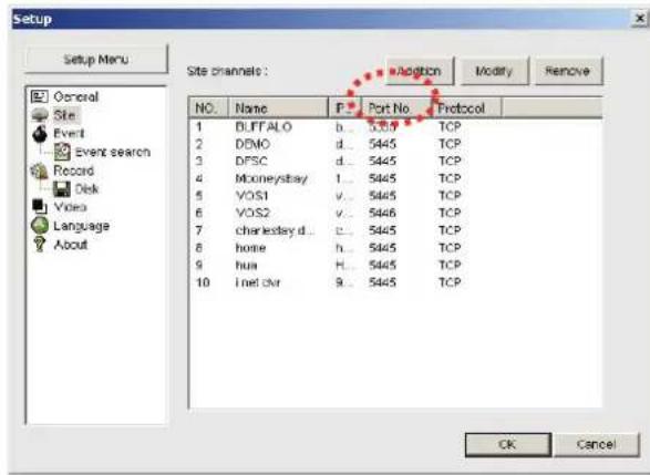

- Site Name: Input the name of the DVR.
- IP Address: Input the Domain Name that is registered on http://www.vitekddns1.com
(EX. XXXXX.vitekddns1.com) - Port Number: Input the port number.
- Protocol: Select TCP.
-
Password: Input the network password.
-
Click CONNECT button. Then the Connect window is displayed.
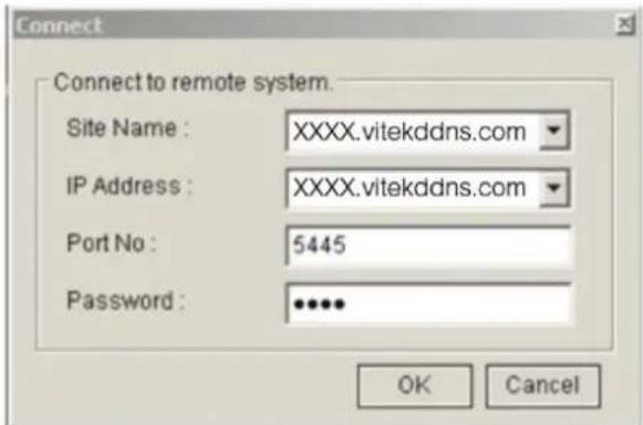
-
Select the site that you wish to access and click OK.
-
Selécione el sitio quie usted desea acceder y haga clic en „Ok“
-
Click
-
Run the pre-install the network client software on the supplied CD. (Refer to Chapter 6. Network access using the Exclusive network viewer)
registration.
Conctese al sistema usando un router o un ADSL modem y un cable Ethernet (10BASE-T/100BASE-TX CAT 5 LAN cable)
• Internet (ADSL) Conway utilizing DBNS

OK.
Network utilized and software exclusive network viewer)

This website wants to install the following add-on: VITEK-WEVALUECAST, from VITEK INDUSTRIAL INC.; if you trust the website and the add-on and want to install it, click here.
Confirgaçation général Confirgaçation les opciones de seguridad, la ruta d convexion automática.


respaldo..


simultaneous.

pantalla.

“Next”
oprima „Next“.

- Resolution: 1024x768
• VGA memoria: 16MB (64MB o mayor es recomendable.)
• Memoria: 256MB (512MB o mayor es recomendable.)
• CPU: Intel Pentium IV 1.2GHz o mayor
5-1. Requirements Minimos de la PC

- PPLAYER: Reproducort de video exclusivo.
<16:05:28> CH3:MANUAL
<16:05:27> CH2:MANUAL
<16:05:24> CH1:MANUAL
<15:18:38> CH4:CONTINUOUS
<15:08:38> CH3:CONTINUOUS
<15:07:38> CH2:CONTINUOUS
<15:07:28> CHI:CONTINUOUS
<15:06:28> CH4:MANUAL
<15:05:28> CH3:MANUAL
<15:05:27> CH2:MANUAL
<15:05:24> CH1:MANUAL
(1/2) 2006/12/12
LIST
TYPE A M S R C
CHANNEL 1 2 3 4
26 27 28 29 30 31
19 20 21 22 23 24 25
12 13 14 15 16 17 18
5 6 7 8 9 10 11
1 2 3 4
20/9007
SEARCH
1-3-3. Sensor and alarm connections
. Concession Internet (ADSL)
Router IP o HUB
![graph TD A["Server"] --> B["Printer"] B --> C["Control Panel"] C --> D["Display"] C --> E["USB"] C --> F["Control Panel"] style A fill:#f9f,stroke:#333 style B fill:#ccf,stroke:#333 style C fill:#cfc,stroke:#333 style D fill:#fcc,stroke:#333 style E fill:#cff,stroke:#333 style F fill:#ffc,stroke:#33…](/content/2026/05/1008175/images/c896c2f05f953e304d23c83d38e2a5984a67812b49d630398f3e014d851eea30.jpg)
Concertando el sistema, empleando un hub (Switching hub) y un cable Internet (10BASE-T/100BASE-TX CAT 5 LAN cable)
Cable Tipo Cruzado • Appendix LAN - Empieando un switching hub

switcher hub.
Operation QUDPLEX simulates, garbage, reproduction, network, y respaldo.

Industry Leading H.264 Commission Code






Compression de video H.264
Caracteristics Principles
adecuadamente.
- Do not place heavy objects on connected units.
Canales con Compression H.264
Video Grabadora Digital de 4, 8, y 16
Serie VT-H
INDUSTRIAL VIDEO PRODUCTS, INC.
VITETK


- SAFETY PRECAUTIONS
- EXPLANATION OF SYMBOLS
- WARNING
- CAUTION
- PRECAUTIONS FOR SUPPLIED AC ADAPTOR
- MAIN FEATURES
- SYSTEM COMPONENTS AND INSTALLATION
- REQUIREMENTS FOR INSTALLATION AND SAFETY
- MAIN REPLACEMENT PARTS
- COMPONENTS
- INDEX
- NAME & FUNCTION .... 10
- SETTING UP THE DVR....15
- 2-5. NETWORK....23
- NAME & FUNCTION
- 1-1. FRONT PANEL
- 1-2. REMOTE CONTROLLER
- 1-3. REAR PANEL AND CONNECTION
- 1-3-1. BASIC CONNECTIONS
- 1-3-2. NETWORK CONNECTIONS
- NOTICE
- 1-3-3. SENSOR AND ALARM CONNECTIONS
- SETTING UP THE DVR
- 2-1. SETUP - MAIN SCREEN
- 2-2. SETUP - LIVE MODE
- 2-3. SETUP - RECORDING MODE
- 2-3-1. MOTION ZONES
- 2-3-2. RECORDING SCHEDULES
- 2-4. SYSTEM
- 2-5. NETWORK
- 2-5-1. PORTS
- NETWORK ACCESS BEYOND ROUTER
- 2-5-2. NETWORK TYPES
- 2-5-2-1. LAN
- 2-5-2-2. DHCP
- 2-5-2-3. ADSL (PPPOE)
- 2-6. STORAGE
- LIVE & SEARCH
- 3-1. LIVE WINDOW
- 3-2. SEARCH WINDOW
- 3-2-1. EVENT SEARCH
- 3-2-2. TIME LINE SEARCH
- 3-2-3. GO TO
- 3-2-4. GO FIRST
- 3-2-5. GO LAST
- 3-2-6. LOG LIST
- 3-2-7. ARCHIVE SEARCH
- 3-3. PLAYBACK MODE
- ARCHIVING AND BACKUP
- 4-1. ARCHIVING STILL IMAGES OR VIDEO
- 4-2. BACKUP STILL IMAGES OR VIDEOS ON USB MEMORY STICK
- FIGURE 4.2.1. ARCHIVE SEARCH SCREEN
- 4-3. PLAYING BACKUP FILE
- NETWORK ACCESS USING THE NETWORK VIEWER
- 5-1. PC REQUIREMENTS
- 5-2. INSTALLING THE NETWORK VIEWER
- 5-3. LIVE MONITORING MODE AND FUNCTIONS
- OPERATIONS OF THE DISPLAY MODE OF THE MAIN SCREEN
- IMAGE CAPTURE OF LIVE SCREEN
- 5-4. BI DIRECTIONAL AUDIO
- 5-5. REMOTE SEARCH MODE AND FUNCTIONS
- SEARCHING AND PLAYING VIDEO FROM THE REMOTE DVR
- BACKUP OF VIDEO ON THE REMOTE DVR
- 5-6. PC SYSTEM CONFIGURATION
- SETTING GENERAL
- SETTING SITE
- SETTING EVENT
- SETTING RECORD
- SETTING VIDEO
- SETTING LANGUAGE
- NETWORK - BY A WEB-BROWSER VIEWER
- APPENDIX: HOW TO CONNECT TO A NETWORK
- HOW TO SET THE IP ADDRESS OF THE DVR AND OPEN THE TCP PORT OF THE ROUTER
- HOW TO ACCESS THE DVR FROM REMOTE PC
- LAN CONNECTION - USING A SWITCHING HUB
- INTERNET (ADSL) CONNECTION USING DDNS
- CARACTERISTICS PRINCIPLES
Brand : Vitek
Model : VT-H160
Category : Digital Video Recorder