
WSWM22 - Speaker Stand SANUS - Free user manual and instructions
Find the device manual for free WSWM22 SANUS in PDF.

| Product Type | Speaker Stand |
| Brand | Sanus |
| Model | WSWM22 |
| Height (Minimum) | 28 inches (71.1 cm) |
| Height (Maximum) | 40 inches (101.6 cm) |
| Weight Capacity | 20 lbs (9.1 kg) per stand |
| Base Dimensions | 12.5 x 12.5 inches (31.8 x 31.8 cm) |
| Top Plate Dimensions | 6.5 x 6.5 inches (16.5 x 16.5 cm) |
| Material | Steel with powder coat finish |
| Color | Black |
| Mounting Hole Pattern | Up to 4.5 inches (11.4 cm) wide |
| Cable Management | Internal cable routing channels |
| Height Adjustment | Tool-free, push-button mechanism |
| Base Type | Wide base with rubber feet |
| Assembly Required | Yes, basic tools included |
| Warranty | 5 years |
| Country of Origin | China |
| Package Quantity | 2 stands per box |
| Recommended Speaker Size | Bookshelf speakers up to 20 lbs |
Frequently Asked Questions - WSWM22 SANUS
User questions about WSWM22 SANUS
0 question about this device. Answer the ones you know or ask your own.
Ask a new question about this device
Download the instructions for your Speaker Stand in PDF format for free! Find your manual WSWM22 - SANUS and take your electronic device back in hand. On this page are published all the documents necessary for the use of your device. WSWM22 by SANUS.
USER MANUAL WSWM22 SANUS
WIRELESS SPEAKER WALL MOUNT
INSTRUCTION MANUAL

natural_image
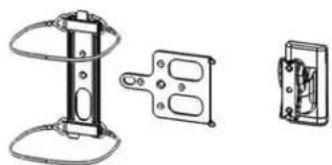
Technical line drawings of three mechanical components: a flat panel, a vertical support frame with coiled cable, and a multi-block housing (no text or symbols)WE'RE HERE TO HELP
If you have any questions along the way, our US-based install experts are standing by to help.

Call us at: 800-359-5520

Or, chat at: SANUS.com/chatSP

CAUTION: IMPORTANT SAFETY INSTRUCTIONS — PLEASE READ ENTIRE MANUAL PRIOR TO USE — SAVE THESE INSTRUCTIONS
Before getting started, let's make sure this product is perfect for you!
This mount is designed to support Sonos ^® One ^TM , PLAY:1 ^TM and PLAY:3 ^TM speakers, as well as other wireless speakers with similar mounting holes.
CAUTION: Avoid potential personal injuries and property damage!
- Check your speaker owner's manual to see if there are any special requirements for mounting your speaker.
- Please read through these instructions completely to be sure you're comfortable with this easy install process.
- Do not use this product for any purpose not explicitly specified by manufacturer.
● Manufacturer is not responsible for damage or injury caused by incorrect assembly or use. - The wall must be capable of supporting five times the weight of the speaker and mount combined.
- If you do not understand these instructions or have doubts about the safety of the installation, assembly or use of this product, contact Customer Service at 1-800-359-5520.
Speaker Weight Limit DO NOT EXCEED
One™
PLAY:1 ^TM

PLAY:3 ^TM
[and other speakers]

Tools Needed

Pencil
Level
Screwdriver

Electric Drill
Wood Stud Install

Stud Finder

Awl
Drill Bit
Concrete Install

Hammer
Drywall Install

Hammer
Drill Bit
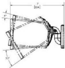
Dimensions
TV INTERFACE
![2x Ø0.26 [6.4] 0.45 [11.5] 2.0 [83.3] 3.83 [97.2] 1.72 [60.6]](/content/2026/05/1041220/images/58c0498f9f2be0250080cad787e41189fca93fc1e9610a9c6872a83a97412df7.jpg)
3-D
natural_image
Technical line drawing of three mechanical components: a vertical support structure, a rectangular bracket with circular cutouts, and a separate electrical outlet (no text or symbols)WALL PLATE
![0.25 [8.4] Ø7.20[5.1] BIK3 Ø1.20 [5.1] 5.00 1.75 [46.0] 3.10 [76.1] 3.80 [98.9]](/content/2026/05/1041220/images/3688709b870894e02f107a04eec1c5d1dc7152b54a2a8827f6c99fad2e846294.jpg)
TOP VIEW - SONOS® One™ / PLAY:1™
SIDE VIEW - SONOS® One™/PLAY:1™
FULLY ASSEMBLED MOUNT
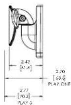
TOP VIEW - SONOS® PLAY:3™

SIDE VIEW - SONOS® PLAY:3™
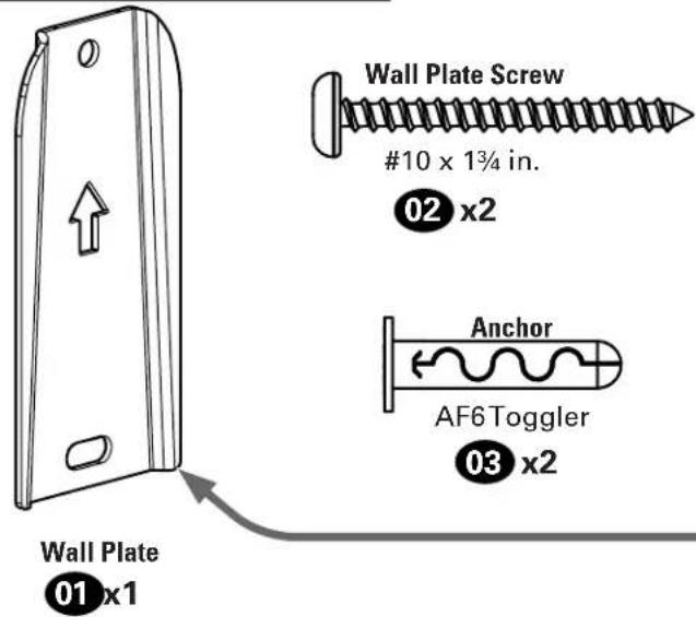
Supplied Parts and Hardware
WARNING: This product contains small items that could be a choking hazard if swallowed.
Before starting assembly, verify all parts are included and undamaged. If any parts are missing or damaged, do not return the damaged item to your dealer; contact Customer Service. Never use damaged parts!

NOTE: Not all hardware included will be used.
Quantities shown are for one speaker mount.
STEP 1 Parts and Hardware

natural_image
Technical diagram of a mechanical device with labeled parts (a and b), showing internal components and connections without any readable text or symbols.STEP 2 Parts and Hardware
natural_image
Technical line drawing of a mechanical component with a curved housing and mounting bracket (no text or symbols)Mount
04 x1

natural_image
Technical line drawing of a mechanical bracket with multiple oval cutouts and mounting holes (no text or symbols)Play:3™ Interface
05 x1
Sonos One™ Interface
06 x1
Interface Screw
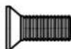
10-24 x 1/2 in.
08 x1
Speaker Screw
(and Other Wireless Speakers)

1/4-20 x 10mm
09 x1
STEP 3 Part
natural_image
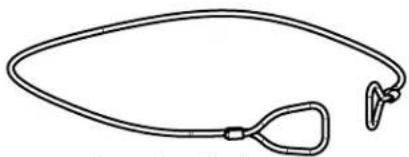
Simple line drawing of a medical or anatomical device with a loop and handle (no text or symbols)Sonos One™ wire
07 x2
Adjustments
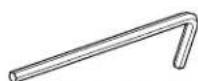
ResetTool
11x1
STEP 1A
Drywall Only InstallationAttach Wa
CAUTION: Avoid potential personal injury or property damage!
- Drywall covering the wall, must not be less than 1/2 in. (12.7 mm)
1 Mark hole locations BETWEEN studs.

2 Drill two holes.
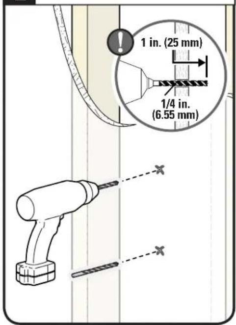
3 Insert two Anchors, flush with drywall.
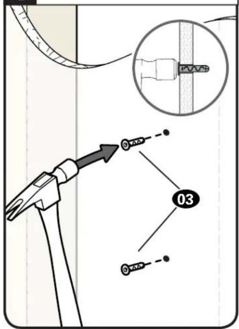

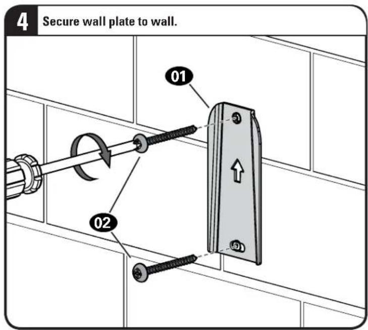
CAUTION: Avoid potential personal injury or property damage!
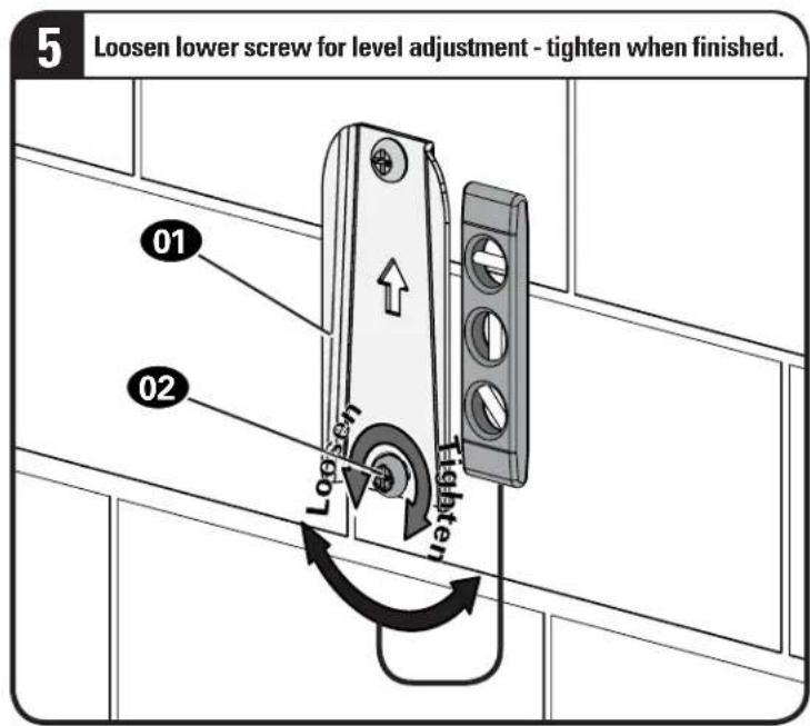
Both screws 02 MUST BE firmly tightened to prevent unwanted movement of the wall plate 01. Ensure the wall plate is securely fastened to the wall before continuing on to the next step.


STEP 1B
Wood Stud InstallationAttach Wall

CAUTION: Avoid potential personal injury or property damage!
- Drywall covering the wall, must not exceed 5/8 in. (16 mm)
Minimum wood stud size: nominal 2 x 4 in. (51 x 102 mm) actual 1½ x 3½ in. (38 x 89 mm)
• Stud center must be verified
1
Locate your stud CENTER.

2
Mark two hole locations.

3
Drill two holes.

CAUTION: Avoid potential personal injury or property damage!
Both screws 02 MUST BE firmly tightened to prevent unwanted movement of the wall plate 01. Ensure the wall plate is securely fastened to the wall before continuing on to the next step.

STEP 1C
Attach Wall Plate to Wall
Solid Concrete or Concrete Block Installation
CAUTION: Avoid potential personal injury or property damage!
- Mount the wall plat 01 directly onto the concrete surface (no wall covering)
• Minimum solid concrete thickness: 8 in. (203 mm)
• Minimum concrete block size: 8 x 8 x 16 in. (203 x 203 x 406 mm)
1 Mark two hole locations.

2 Drill two holes.

3 Insert two Anchors, flush with drywall.

CAUTION: Avoid potential personal injury or property damage!
Both screws 02 MUST BE firmly tightened to prevent unwanted movement of the wall plate 01. Ensure the wall plate is securely fastened to the wall before continuing on to the next step.
STEP 2
Attach Mount to Speaker

Based on your speaker model, follow the correct STEP 2 below.
Sonos® One™
[only]
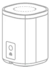
natural_image
Line drawing of a cylindrical appliance with a lid and control panel (no text or symbols)STEP 2A/2B
PAGE 13 PAGE 18
Sonos® PLAY:1™
[and other speakers]
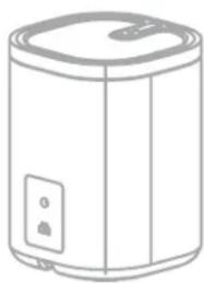
natural_image
Line drawing of a cylindrical water heater with lid and control panel (no text or symbols)STEP 2C
Sonos® PLAY:3™
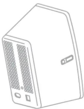
natural_image
Line drawing of a server rack unit with ventilation slots and ports (no text or symbols)STEP 2D VERTICAL
PAGE 19 PAGE|20
Sonos® PLAY:3™
Horizontal InstallationVertical

natural_image
Line drawing of a microwave oven with ventilation grilles and control buttons (no text or symbols)STEP 2E HORIZONTAL
STEP 2A/2B
Attach Mount to Speaker SOIOS
® One™

For a helpful install video, search your model at SANUS.com.

TIP: Set up your Sonos® speaker prior to mounting.
! Follow the step below based on your installation.
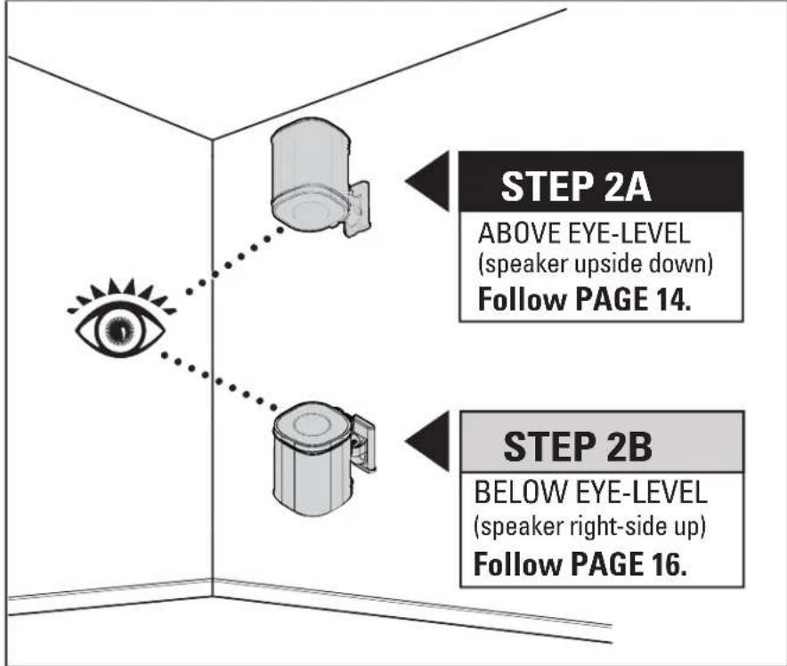
STEP 2A

Above Eye Level
Attach Mount to Speaker SO
ios
® One™
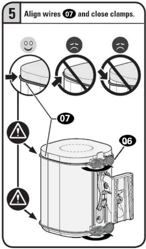
1 Attach interface 06 to mount 04 with screw 08.

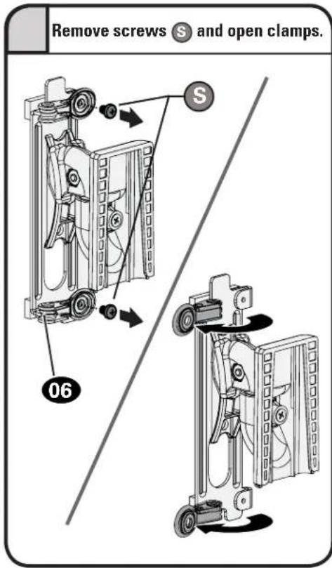
2 Remove screws Ⓞ and open clamps.
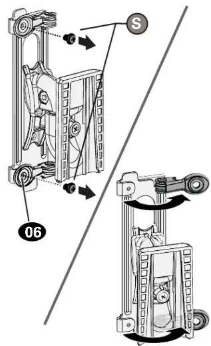
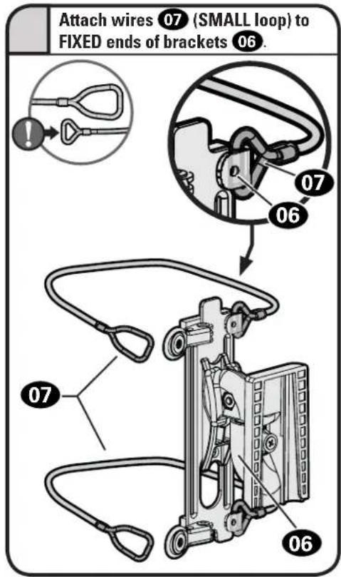
3 Attach wires 07 (SMALL loop) to FIXED ends of bracket 06.
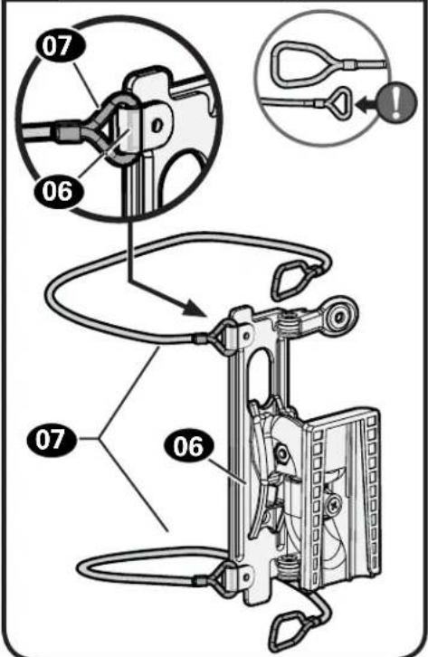

CAUTION: Avoid potential personal injury or property damage! Wires 07 must NOT extend beyond the speaker's end caps.
flowchart
graph TD
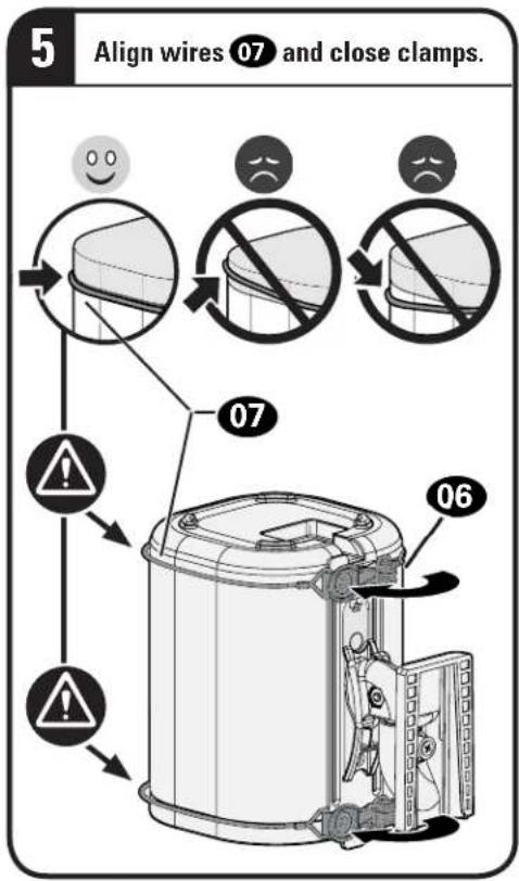
A["5 Align wires 07 and close clamps."] --> B["1"]
B --> C["2"]
C --> D["3"]
D --> E["4"]
E --> F["5"]
style A fill:#f9f,stroke:#333
style B fill:#ccf,stroke:#333
style C fill:#cfc,stroke:#333
style D fill:#fcc,stroke:#333
style E fill:#cff,stroke:#333
style F fill:#ffc,stroke:#333
CAUTION: Avoid potential personal injury or property damage! Both screws ⚫ MUST BE installed to secure the speaker to the mount.

STEP 2B

Below Eye Level
Attach Mount to Speaker SO
10S
® One™

CAUTION: Avoid potential personal injury or property damage! Wires 07 must NOT extend beyond the speaker's end caps.
flowchart
graph TD
    A["06"] --> B["07"]
    B --> C["Align wires 07 and close clamps."]
    style A fill:#f9f,stroke:#333
    style B fill:#ccf,stroke:#333
    style C fill:#cfc,stroke:#333
CAUTION: Avoid potential personal injury or property damage! Both screws ⚫ MUST BE installed to secure the speaker to the mount.

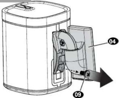
STEP 2C
Attach Mount to Speaker SO
10S
® PLAY:1™ [and other speakers]
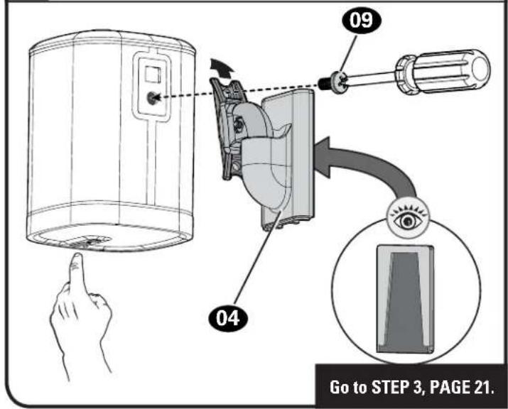
Attach the mount 04 to your speaker with the speaker screw 09.

NOTE: Speaker may be installed in either the right-side-up position a or up-side-down position b, depending on height placement.
a Right-Side-Up for BELOW Eye Level.

b Up-Side-Down for ABOVE Eye Level.
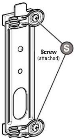
STEP 2D - (VERTICAL)
Attach Mount to Speaker SO
10S
® PLAY:3™
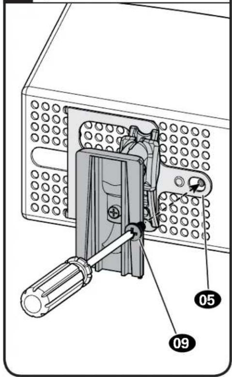
1 Attach interface 05 to mount 04 with interface screw 08

2 Insert both legs Ⓛ into the 4th holes from the top, to align the screw hole Ⓗ.
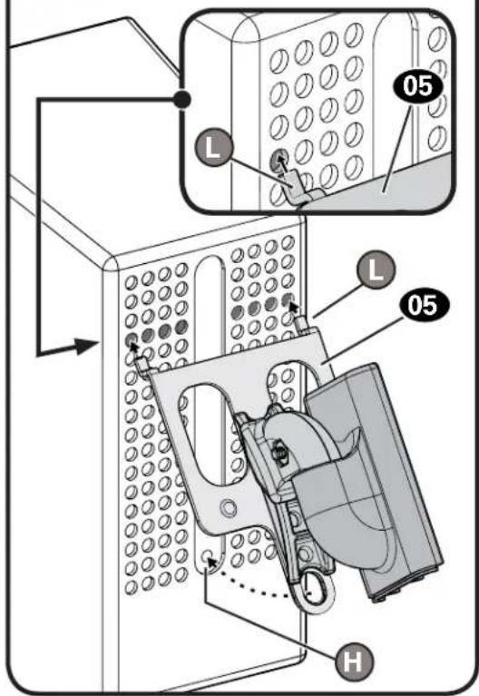
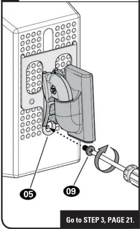
3 Secure the assembly with the speaker screw 09.
STEP 2E - (HORIZONTAL)
Attach Mount to Speaker SONOS
® PLAY:3 ^TM
1 Attach interface 05 to mount 04 with interface screw 08.

2 Insert both legs Ⓛ into the 4th holes from the end, to align the screw hole Ⓗ.

3 Secure the assembly with the speaker screw 09.
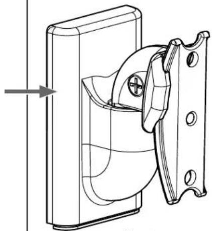
STEP 3
Mount Assembly to Wall Plate
1 Install cables
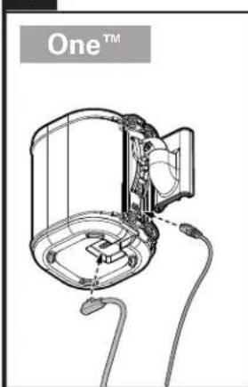
natural_image
Technical line drawing of a device with labeled 'One™' and internal components (no readable text or symbols beyond label)PLAY:1™
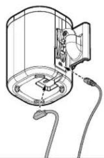
natural_image
Diagram of a cylindrical device with internal components and wiring, no text or symbols presentHORIZONTAL SHOWN
PLAY:3TM
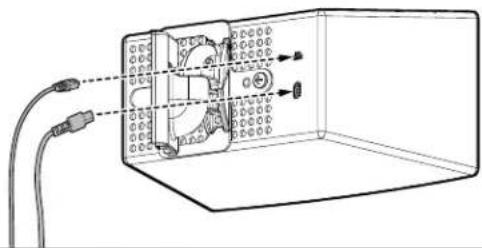
natural_image
Diagram of a device inside a transparent enclosure with wiring and connectors (no text or symbols)2
Slide onto wall plate 01
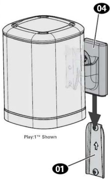
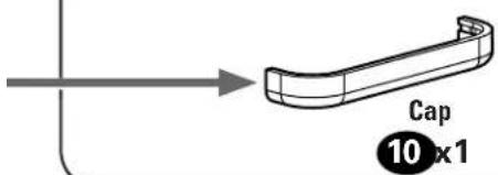
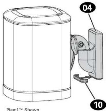
3
Slide cap 10 onto mount 04

natural_image
Illustration of a hand holding a device with a numbered label pointing to the base (no text or symbols on the device itself)Adjustments
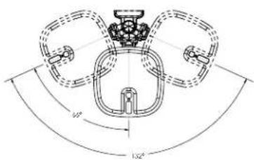
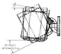
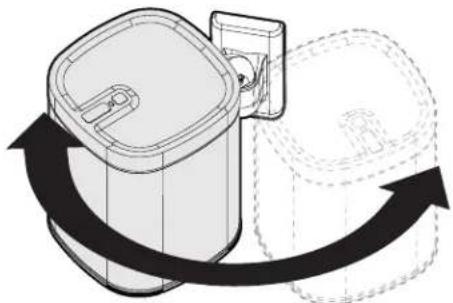
TILT SV
Your speaker can tilt up or down. Your speaker can

natural_image
Technical line drawing of a mechanical component with curved arrows indicating rotation or movement (no text or symbols)swivel left or right.
natural_image
Diagram of a cylindrical device with a side panel and a curved arrow indicating rotation or movement (no text or symbols present)Play:1 ^TM Shown
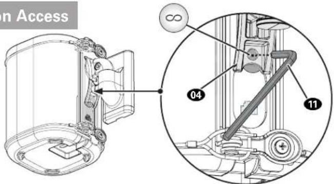
One™ Reset Button Access

Access your
Sonos® Infinity
button, through
the hole on mount 04,
using tool 11.

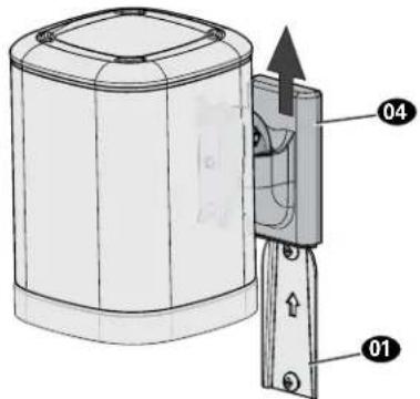
To Remove
One™
PLAY:1™
PLAY:3TM
[and other speakers]

natural_image
Technical line drawing of a device with a labeled component (no text or symbols on the diagram itself)
One™


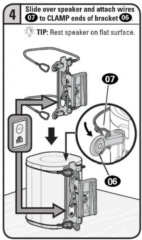
IMPORTANT: Set on flat surface.
PLAY:1™
[and other speakers]
PLAY:3™

ESPAÑOL
Thank you for choosing SANUS! Please take a moment to let us know how we did:

Call us: 1-800-359-5520

Email us: info@sanus.com

Leave a review: sanus.com
Milestone AV Technologies and its affiliated corporations and subsidiaries (collectively, "Milestone"), intend to make this manual accurate and complete. However, Milestone makes no claim that the information contained herein covers all details, conditions, or variations. Nor does it provide for every possible contingency in connection with the installation or use of this product. The information contained in this document is subject to change without notice or obligation of any kind. Milestone makes no representation of warranty, expressed or implied, regarding the information contained herein. Milestone assumes no responsibility for accuracy, completeness or sufficiency of the information contained in this document.
©2017 Milestone AV Technologies. All rights reserved. SANUS is a division of Milestone.
All other brand names or marks are used for identification purposes and are trademarks of their respective owners.
SANUS • 6436 City West Parkway • Eden Prairie, MN 55344 USA 6901-602165 00


- WIRELESS SPEAKER WALL MOUNT
- INSTRUCTION MANUAL
- WE'RE HERE TO HELP
- CAUTION: IMPORTANT SAFETY INSTRUCTIONS — PLEASE READ ENTIRE MANUAL PRIOR TO USE — SAVE THESE INSTRUCTIONS
- Before getting started, let's make sure this product is perfect for you!
- Speaker Weight Limit DO NOT EXCEED
- Tools Needed
- Dimensions
- Supplied Parts and Hardware
- STEP 1A
- Drywall Only InstallationAttach Wa
- CAUTION: Avoid potential personal injury or property damage!
- STEP 1B
- Wood Stud InstallationAttach Wall
- STEP 1C
- Attach Wall Plate to Wall
- Solid Concrete or Concrete Block Installation
- STEP 2
- Attach Mount to Speaker
- Based on your speaker model, follow the correct STEP 2 below.
- STEP 2A/2B
- STEP 2C
- Attach Mount to Speaker SOIOS
- ® One™
- STEP 2A
- Attach Mount to Speaker SO
- STEP 2B
- STEP 2D - (VERTICAL)
- STEP 2E - (HORIZONTAL)
- Attach Mount to Speaker SONOS
- ® PLAY:3 TM
- STEP 3
- Mount Assembly to Wall Plate
- Adjustments
- TILT SV
- One™ Reset Button Access
- To Remove
- ESPAÑOL
Brand : SANUS
Model : WSWM22
Category : Speaker Stand