
UF30 - Speaker Stand SANUS - Free user manual and instructions
Find the device manual for free UF30 SANUS in PDF.


| Product Type | Speaker Stand |
| Brand | Sanus |
| Model | UF30 |
| Height | 30 inches (762 mm) |
| Base Diameter | 12 inches (305 mm) |
| Top Plate Size | 6 x 9 inches (152 x 229 mm) |
| Weight Capacity | 50 lbs (22.7 kg) per stand |
| Product Weight | 12 lbs (5.4 kg) each |
| Material | Steel with black finish |
| Power Source | None (passive stand) |
| Main Function | Floor-standing support for bookshelf speakers |
| Assembly Required | Yes, basic tool needed |
| Stability Features | Rubber feet and anti-tip base |
| Cable Management | Integrated channel for hiding wires |
| Care and Cleaning | Wipe with a dry cloth; avoid liquids |
| Safety Warning | Do not exceed weight limit; ensure level surface |
| Spare Parts Availability | Contact Sanus customer service for replacement parts |
| Repairability | Limited; no user-serviceable components |
| Warranty | 5-year limited warranty |
| Compatibility | Most bookshelf speakers up to 50 lbs |
Frequently Asked Questions - UF30 SANUS
User questions about UF30 SANUS
0 question about this device. Answer the ones you know or ask your own.
Ask a new question about this device
Download the instructions for your Speaker Stand in PDF format for free! Find your manual UF30 - SANUS and take your electronic device back in hand. On this page are published all the documents necessary for the use of your device. UF30 by SANUS.
USER MANUAL UF30 SANUS
the next section. To utilize the steel speaker studs, simply thread them into the holes in the corners of the top plates until the end protrudes 1/8 inch through the bottom. Place your speaker on the steel speaker studs.(Photo 5) Insert the small allen key into the bottom of each steel speaker stud and adjust them until the speaker is level and does not rock back and forth. Lock in place with a machine nut. Use of the steel speaker studs is optional.* The Rubber Pads are provided as an alternative and may be placed in Simply twist the pads into the holes in the corner.

natural_image
Close-up of a small golden cone-shaped object on a dark surface, no visible text or symbols6] A number of manufacturers are providing threaded inserts on the bottom of their speakers for the new Foundation Mount™ system. The Foundation Mount™ system allows you to bolt your speaker to the top plate using the speaker bolts and the remaining allen key provided. This system provides significant safety benefits when used in earthquake areas or around pets and children. It also offers maximum resonance damping characteristics. The rubber pads should be sandwiched between the top plate and the speaker to provide superior damping and prevent damage to the speaker. Do not use the steel speaker studs when bolt mounting.
*NOTE: The ends of the spiked feet and steel speaker studs are very sharp and may scratch floors or furniture. All sharp objects can be hazardous to children. For this reason rubber pads are provided as an option. The decision to use spiked feet and/or speaker studs is yours; Sanus Systems will not be liable for damage or injury.
Every effort has been made to ensure that your stands are perfect. If you have any questions or feel that there is a problem of any kind, please contact SanusCustomer Support. We can assist with questions or damaged/missing parts. Customer Support (800) 359-5520 or www.sanus.com
Page 4 2221 Highway 36 W St. Paul MN 55113 800.359.5520 www.sanus.com

SANUS SYSTEMS
THE UNION OF FORM AND FUNCTION
ULTIMATE FOUNDATIONS®
INSTRUCTION MANUAL

natural_image
Black wooden stand with four legs and a speaker block, no visible text or symbolsPage 1
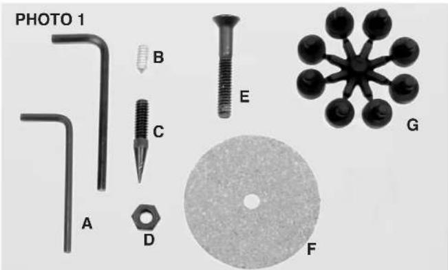

Hardware List (Photo 1, 2, & 3)
A] allen keys (3)
B] steel speaker studs (8)
C] spiked feet (6)
D] nuts (14)
E] 1.75" flat head bolts (6)
F] damping washers (6)
G] rubber pads (2 discs of 8)
H] 2" rubber isolation rings (6)
II] NuStone bases (2)
J] NuStone feet (6)
K] 2" round head bolts (6) not pictured
L] top plates (2) not pictured
M] pillars (6) not pictured
N] 5/8" speaker bolts (2) (For Boston Acoustics VRM series and other bolt-mount speakers.) not shown
'Take the time to find the right speaker locations for your listening room.'
1] Attach three rubber isolation rings to each NuStone base. (Photo 2) Attach three NuStone feet to each NuStone base. (Photo 3)
2] Group three pillars with each NuStone base. Notice that the bolt holes are countersunk on one side of the base; this side is the bottom and faces away from the pillar. Align the countersunk holes in the base with the holes in either end of the pillars. Bolt the pillars and the base together using the long 2" round head bolts. Do not tighten! If the pillars are not loose, you will not be able to attach the top plate in the next step.
3] Notice that the bolt holes are countersunk on one side of the top plates; this is the top side and faces away from the pillars. Adhere the two inch self adhesive damping washers to the bottom side of each top plate. The holes in the damping washers line up with the holes in the top plate. The damping washers will be sandwiched between the top plate and the pillars. (Photo 4) Align the countersunk holes in the top plate with corresponding holes in the top of each pillar. With the large allen key, bolt the pillars and the top plate together using the 1.75^n bolts. Tighten, then flip the stand over and tighten the NuStone base bolts.
4] Both spiked feet and rubber pads are provided for your Ultimate Foundations®. The spiked feet are preferable in terms of performance. Simply thread a machine nut over the spiked feet and thread the ends of the spiked feet into the threaded holes in the NuStone feet. Adjust the spiked feet until
the stand is level and lock into place by tightening the machine nut. Use of the spiked feet is optional.* The Rubber Pads are provided as an alternative and may be placed in the corners of the top plates. Twist the pads into the holes in the corners of each top plate.
5] Three forms of speaker mounts are provided – steel speaker studs, rubber pads and the new Foundation Mount™ which is discussed in

natural_image
Close-up of a black cylindrical object with a white ring, labeled 'PHOTO 4' in the top-left corner (no other text or symbols visible)Page 3 * PLEASE READ THE NOTE ON PAGE 4 OF THIS MANUAL!


Brand : SANUS
Model : UF30
Category : Speaker Stand