
SASB1 - Speaker Stand SANUS - Free user manual and instructions
Find the device manual for free SASB1 SANUS in PDF.


| Product Type | Soundbar Mount |
| Brand | Sanus |
| Model | SASB1 |
| Maximum Weight Capacity | 20 lbs (9.0 kg) |
| Mount Weight (approx.) | 2 lbs (0.9 kg) |
| Adjustable Width Range | 6.6 in to 35.5 in |
| Height Adjustment | Yes, via release cord |
| Depth Adjustment | Yes, for back and bottom mount installations |
| Mounting Compatibility | UL/TUV certified TV wall mounts |
| Soundbar Mounting Options | Back keyhole slots, back threaded inserts, bottom threaded inserts |
| Included Hardware | Horizontal bracket, arm brackets, bottom brackets, spacers, washers, screws, knobs |
| Tools Required | Phillips screwdriver, level |
| Maintenance | Wipe clean with dry cloth |
| Safety Certification | UL/TUV compliant when used with certified mount |
| Country of Origin | USA (Legrand AV Inc.) |
| Warranty | Contact Legrand AV for details |
| Customer Support | US: 800-359-5520, SANUS.com/chat |
Frequently Asked Questions - SASB1 SANUS
User questions about SASB1 SANUS
0 question about this device. Answer the ones you know or ask your own.
Ask a new question about this device
Download the instructions for your Speaker Stand in PDF format for free! Find your manual SASB1 - SANUS and take your electronic device back in hand. On this page are published all the documents necessary for the use of your device. SASB1 by SANUS.
USER MANUAL SASB1 SANUS
If you have any questions along the way, our US-based install experts are standing by to help.

Call us at: 800-359-5520

Or, chat at: SANUS.com/chatSP

natural_image
Technical line drawing of a mechanical support system with two vertical supports and connecting rods (no text or symbols)IMPORTANT SAFETY INSTRUCTIONS
PLEASE READ ENTIRE MANUAL PRIOR TO USE – SAVE THESE INSTRUCTIONS
Before You Begin
Please verify the following items:
☐ Your TV, soundbar, soundbar mount, and any accessories you plan to install DO NOT EXCEED the specified weight limit of your TV wall mount.
☐ You read and understand these directions.
☐ You refer to the documentation that came with your sound bar, your TV and your TV wall mount for additional guidance.
WARNING:
- This soundbar mount is only designed for use with TV wall mounts that meet UL/TUV safety certifications.
- This soundbar mount is ONLY designed to mount BELOW the television (see Figure 1).
- This soundbar mount is designed to be installed and utilized only as specified in this manual. The manufacturer is not responsible for improper assembly, use, or handling of this product.
- Failure to follow these instructions could result in an unstable situation that may result in property damage or personal injury.

Weight Restrictions
Weight Limit for SASB1
DO NOT EXCEED
20 lbs. (9.0 kg) for this Soundbar Mount

Weight Limit for Your TV Mount
▲ CAUTION: Avoid potential personal injuries and property damage!
The weight of your TV, PLUS this soundbar mount, your soundbar, and any accessories, MUST BE LOWER than the maximum weight rating of your TV mount. See your TV mount's manual for maximum weight allowed.

Items Needed

Phillips Screwdriver
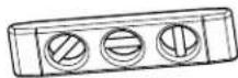
Level

Your TV Mount Manual

natural_image
Technical line drawing of a wall-mounted device with vertical connectors (no text or symbols)UL/TUV Certified TV Wall Mount \*
*Your TV wall mount may vary from the illustrations throughout this manual. NOTE that the procedure to install the soundbar is the same.
PARTS INCLUDED
WARNING: This product contains small items that could be a choking hazard if swallowed. Before starting assembly, verify all parts are included and undamaged. If any parts are missing or damaged, do not return the damaged item to your dealer; contact Customer Service. Never use damaged parts!

NOTE: Not all hardware included will be used.
![Horizontal Bracket 01 QTY.1 Arm Bracket A 02 QTY.1 Arm Bracket B 03 QTY.1 Bottom Bracket 04 QTY.2 05 TV Screws (qty. 4 each) [Only one size fits your TV] M4 M4 x 30mm M4 x 50mm M6 M6 x 30mm M6 x 50mm M8 M8x30 mm M8 x 40mm M8 x 50mm M8 x 65mm 06 Washer (qty. 4 each) M4 Washer Spacer [If necessary] (qty. 4 each) M8/M6 Washer Spacer: 2.5mm 08 QTY.2 Interface Washer 09 QTY.2](/content/2026/05/954024/images/9baf5cb8ab355aaaad036449034e51066db6de3817d1d05dece2d4d6fdc532de.jpg)
![10 Soundbar Screws (qty. 2 each) [Only one size fits your Soundbar] M4 M5 M4 x 10mm M4 x 16mm M5 x 16mm M6 M6 x 16mm Soundbar Washers (qty. 2 each) M4 / M5 Washer M6 Washer 2](/content/2026/05/954024/images/c99dacd5e9e4c579ee39e480f692c2aedf0459353bdd70e02c3dc87bf93dafb0.jpg)

STEP 1: PREPARE YOUR TV [IF MOUNTED]
![SANUS SASB1 - STEP 1: PREPARE YOUR TV [IF MOUNTED] - 1](/content/2026/05/954024/images/6993f9c722f50b80c5a1c584dc234397612ef57556e6d0b50942eb0af801743d.jpg)
![SANUS SASB1 - STEP 1: PREPARE YOUR TV [IF MOUNTED] - 2](/content/2026/05/954024/images/63e69c2828d0b7d2251faf6d818cefc8aa1f4758b172ea499509e1291eea9700.jpg)
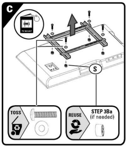
CAUTION: Follow your TV mount's manual for instructions on how to safely remove your TV and TV bracket.
![SANUS SASB1 - STEP 1: PREPARE YOUR TV [IF MOUNTED] - 3](/content/2026/05/954024/images/67acb21056fd3e0f32f5a35a915b185a29806ac849aaf5d1c7e905745b012b91.jpg)
NOTE: Your TV wall mount may vary from the illustrations throughout this manual — the procedure to install the ndbar is the same.
![SANUS SASB1 - STEP 1: PREPARE YOUR TV [IF MOUNTED] - 4](/content/2026/05/954024/images/100cc066a388dea5b8f024087b7998042574edad6dfa3082a9da94226c142f05.jpg)
natural_image
Technical line drawing of a wall-mounted electrical panel with connectors and wiring (no text or symbols)
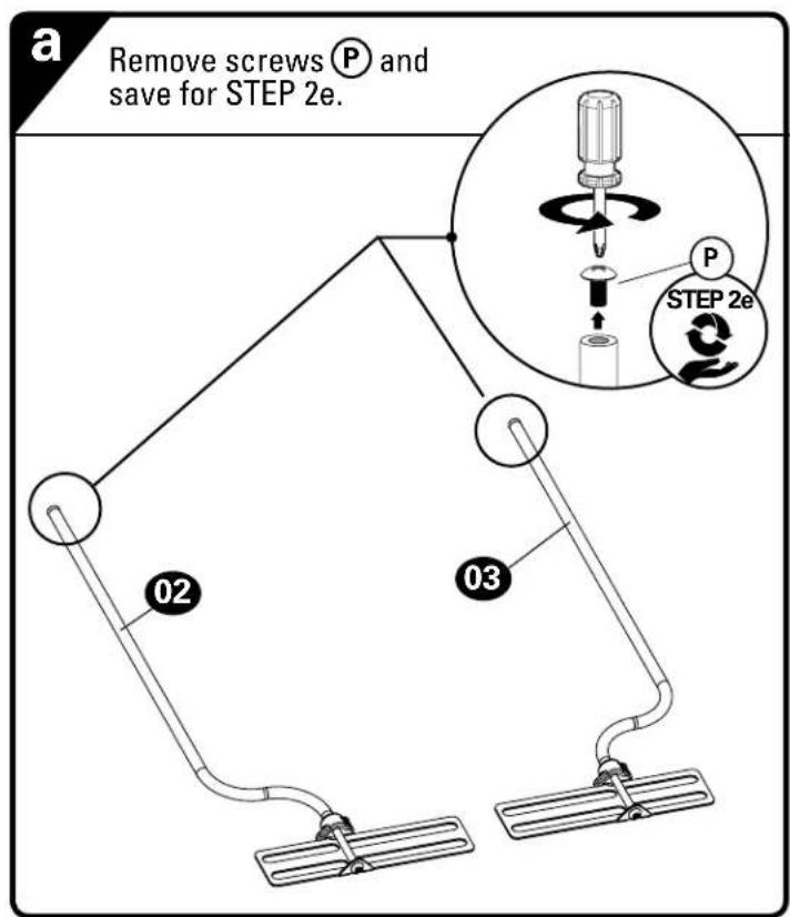
STEP 2: ASSEMBLE SOUNDBAR MOUNT

C
Based on your soundbar measurement, rotate arm brackets 02 / 03 left or right, to align with your soundbar mounting holes, but not overhanging the ends of your soundbar or covering up any cable connections.

6.6 in. to 19.5 in. 20 in. to 31 in. 12 in. to 22.5 in. 22.5 in. to 35.5 in.
d
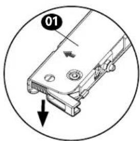
Insert the soundbar arm brackets 02 and 03 into the horizontal bracket 01.
NOTE: Holding the lever inward as shown, helps to slide the arms.


NOTE: The channel of the horizontal bracket 01 will rest ON your TV.

natural_image
Cross-sectional diagram of a device with no visible text or symbols
NOTE: The flat side of the arm brackets 02 and 03 rests ON the soundbar.


natural_image
Prohibition sign showing a crossed-out mechanical component with a downward arrow (no text or symbols)e
Re-attach the screws Ⓟ onto the arm brackets 02 and 03.
CAUTION: The screws Ⓟ MUST be installed to secure the arms to the horizontal bracket 01.

STEP 3: INSTALL THE SOUNDBAR MOUNT ON YOUR TV
Determine which screw diameter fits your TV — M4, M6, or M8.
Only one screw size fits your TV.

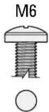
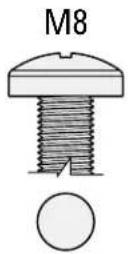
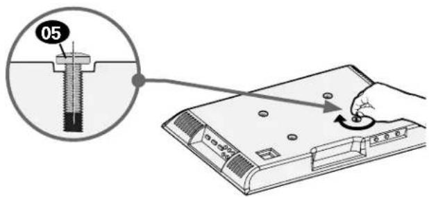
Step 3A Step 3B
- for Flat Back TV
[TV brackets lay flat on your TV] follow Step 3A on PAGE 6.
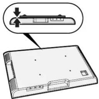
• for Flat Back TV with Extra Space Needed
[for deep inset holes or cable interference]
follow Step 3B on PAGE 7.
• for Rounded or Irregular Back TV
[TV brackets NOT resting flat on your TV]
follow Step 3B on PAGE 7.
Inset Holes Cables Rounded Back
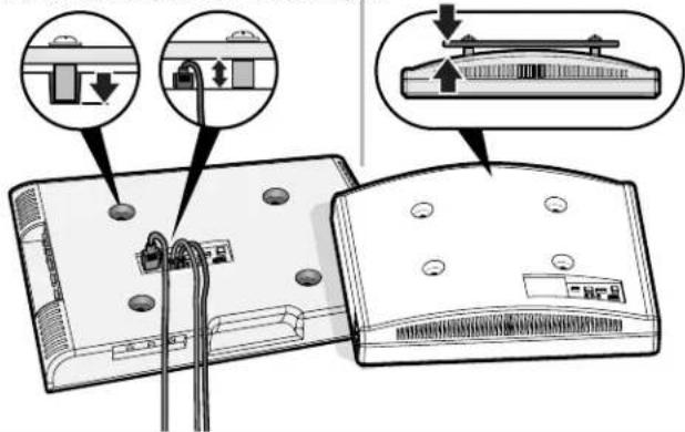
If your TV included inset spacers or wall mount adapters, use them UNDER the soundbar mount hardware.

CAUTION: Verify adequate thread engagement with your screw 05, washer 06, spacer 08/09 combination AND soundbar bracket 01.
— Too short will not hold your TV. — Too long will damage your TV.

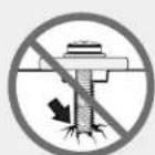
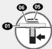
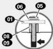
Too Short Too Long Correct Correct
STEP 3A
a
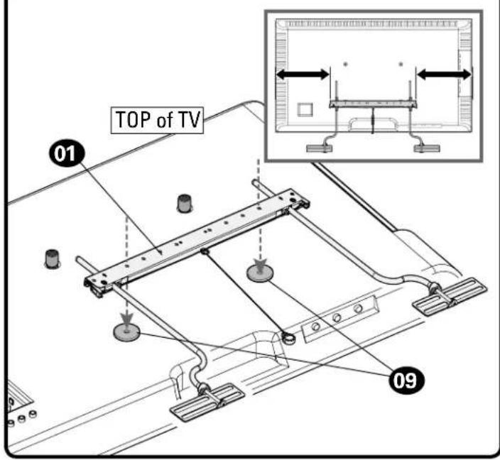
Place the 16mm spacers 08 over your TV's top mounting holes and the interface washers 09 over the bottom mounting holes.

b
Center the soundbar horizontal bracket 01 over the interface washers 09 on your TV's bottom mounting holes.
C
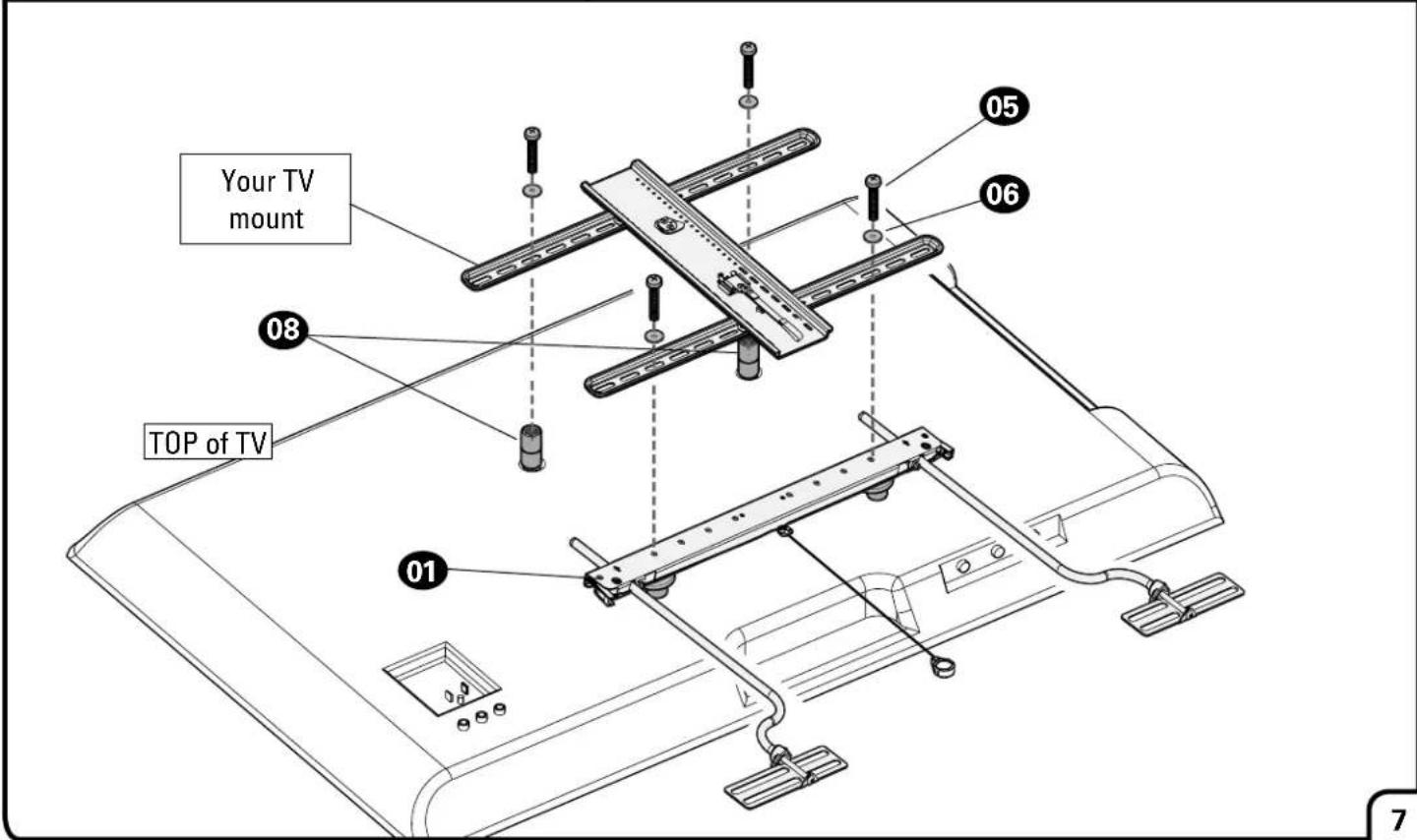
Center your TV mount bracket(s) on top of the 16mm spacers 08 and the soundbar bracket 01.
Secure the TV mount and soundbar mount to your TV using the supplied TV screws 05 and washers 06.
⚠️ CAUTION: be sure to use correct length screws.

STEP 3B
a
Place your TV mount spacers over your TV's mounting holes. Then place the 16mm spacers 08 over the spacer on the top mounting holes and the interface washers 09 over the spacer on the bottom mounting holes.

b
Center the soundbar horizontal bracket 01 over the interface washers 09 on your TV's bottom mounting holes.

C
Center your TV mount bracket(s) on top of the 16mm spacers 03 and the soundbar bracket 01. Secure the TV mount and soundbar mount to your TV using the supplied TV screws 05 and washers 06. CAUTION: be sure to use correct length screws.
STEP 4: INSTALL YOUR SOUNDBAR TO THE ARMS
a
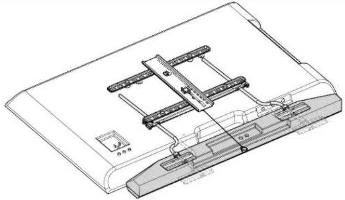
Center your soundbar under the soundbar mount, and adjust the arms 02/03 over your soundbar mount holes.

NOTE: Holding the lever inward as shown, helps to slide the arms.

natural_image
Technical line drawing of a mechanical assembly with no visible text or symbolsb
Attach your soundbar, based on the mounting holes of your soundbar.
Look at the mounting holes on the back or bottom of your soundbar to determine your install method A, B or C.

natural_image
Pure technical diagram of a mechanical component with arrows indicating direction (no text or symbols)4A: Back-Mounted Key hole slots


4B: Back-Mounted Threaded inserts


4C: Bottom-Mounted Threaded inserts


4A: Back-Mounted Key Hole Slots
a
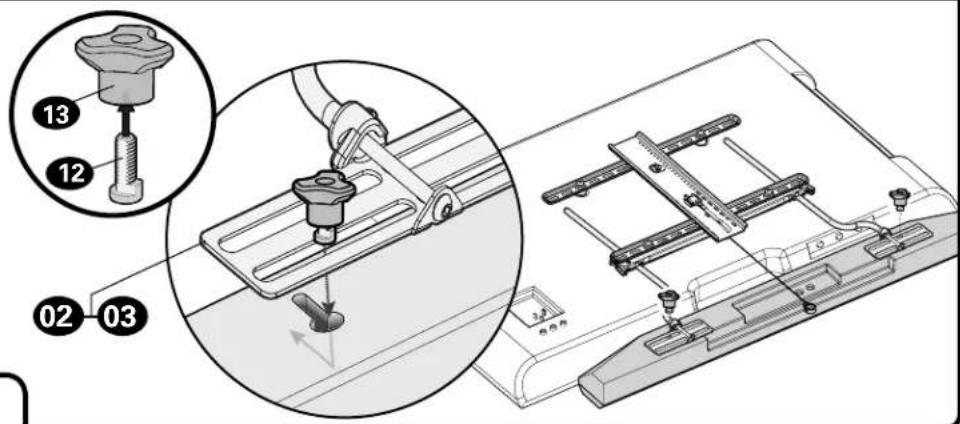
Assemble knobs 13 and keyhole screws 12.
Attach brackets 02 and 03 to your soundbar using the knob assemblies.
b
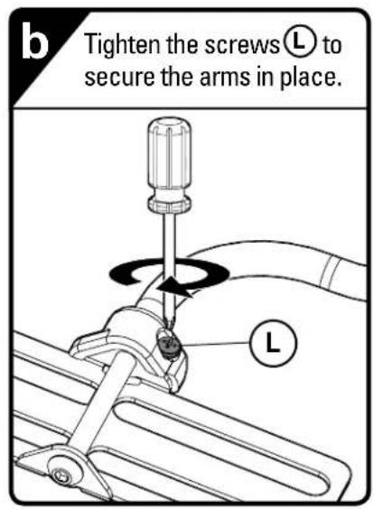
Tighten the screws Ⓛ to secure the arms in place.

natural_image
Mechanical assembly diagram showing a screwdriver inserted into a pipe with a rotating mechanism and a labeled component (no text or symbols beyond the label)4B: Back-Mounted Threaded Inserts

4C: Bottom-Mounted Threaded inserts


STEP 5: HANG YOUR TV
a
BEFORE hanging, verify the depth of your soundbar will not interfere with the wall after mounting your TV. Adjust the depth of your soundbar as needed, by loosening screw Ⓛ. Tighten screw Ⓛ after adjustments.

b
Attach the magnet of release cord Ⓡ, to back of the soundbar mount, for easy access during adjustments.


natural_image
Technical diagram of a mechanical assembly with a labeled component (R) and no visible text or symbols.C
Follow your TV wall mount installation manual to hang your TV assembly.


natural_image
Technical line drawing of a mounted device with cables and connectors (no text or symbols)ADJUSTMENTS
HEIGHT ADJUST:
Pull and hold release cord Ⓡ to raise or lower your soundbar.
CAUTION: be sure to support your soundbar with one hand while moving.

natural_image
Technical line drawing of a mechanical assembly with a hand operating a workpiece (no text or symbols present)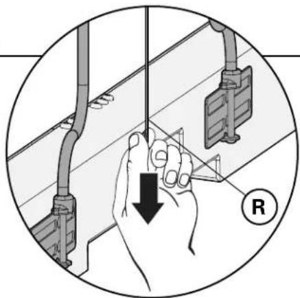
natural_image
Illustration of hands holding a tool with a downward arrow, next to electrical wiring and a meter (no text or symbols)DEPTH ADJUST [For back mount installations]:
- Loosen the knobs or screws, (depending on your installation option), on the back of your soundbar.
- Loosen locking screws Ⓛ.
- Move your soundbar to desired position.
- Tighten all knobs/screws when finished adjustment.

OPTION A:
Back-Mounted
Key Hole Slots
OPTION B:
Back-Mounted
Threaded Inserts
OPTION C:
Bottom-Mounted
Threaded inserts

L
![SANUS SASB1 - DEPTH ADJUST [For back mount installations]: - 3](/content/2026/05/954024/images/322671fdbfa6eead95cfa9399a300950bf7f8572d3b0dc337d078ee67105a1e4.jpg)
natural_image
Technical line drawing of a mechanical assembly with directional arrows indicating movement (no text or symbols)DEPTH ADJUST [For bottom mount installations]:
Loosen the screws on the bottom of your soundbar to slide your soundbar in or out.
Tighten the screws when finished adjustment.
![SANUS SASB1 - DEPTH ADJUST [For bottom mount installations]: - 1](/content/2026/05/954024/images/3e0024d279547b61eecd53f9fa017facb34721ae92b2c295c6292862e280b056.jpg)
natural_image
Technical line drawing of a mechanical assembly with no visible text or symbols
Legrand AV Inc. and its affiliated corporations and subsidiaries (collectively, "Legrand"), intend to make this manual accurate and complete. However, Legrand makes no claim that the information contained herein covers all details, conditions, or variations. Nor does it provide for every possible contingency in connection with the installation or use of this product. The information contained in this document is subject to change without notice or obligation of any kind. Legrand makes no representation of warranty, expressed or implied, regarding the information contained herein. Legrand assumes no responsibility for accuracy, completeness or sufficiency of the information contained in this document.
©2019 Legrand AV Technologies. All rights reserved. Sanus is a division of Legrand. All other brand names or marks are used for identification purposes and are trademarks of their respective owners.
Legrand AV Inc. • 6436 City West Parkway • Eden Prairie, MN 55344 USA
6901-602386-00


- IMPORTANT SAFETY INSTRUCTIONS
- PLEASE READ ENTIRE MANUAL PRIOR TO USE – SAVE THESE INSTRUCTIONS
- Before You Begin
- WARNING:
- Weight Restrictions
- Weight Limit for SASB1
- DO NOT EXCEED
- Weight Limit for Your TV Mount
- Items Needed
- UL/TUV Certified TV Wall Mount \*
- PARTS INCLUDED
- STEP 1: PREPARE YOUR TV [IF MOUNTED]
- STEP 2: ASSEMBLE SOUNDBAR MOUNT
- C
- d
- e
- STEP 3: INSTALL THE SOUNDBAR MOUNT ON YOUR TV
- Step 3A Step 3B
- - for Flat Back TV
- • for Flat Back TV with Extra Space Needed
- • for Rounded or Irregular Back TV
- STEP 3A
- a
- b
- STEP 3B
- STEP 4: INSTALL YOUR SOUNDBAR TO THE ARMS
- 4A: Back-Mounted Key Hole Slots
- 4B: Back-Mounted Threaded Inserts
- 4C: Bottom-Mounted Threaded inserts
- STEP 5: HANG YOUR TV
- ADJUSTMENTS
- HEIGHT ADJUST:
- DEPTH ADJUST [For back mount installations]:
- DEPTH ADJUST [For bottom mount installations]:
Brand : SANUS
Model : SASB1
Category : Speaker Stand