
76AGX51 - Gas cooktop Infiniton - Free user manual and instructions
Find the device manual for free 76AGX51 Infiniton in PDF.


| Type of Product | Refrigerator-Freezer |
| Brand | Infiniton |
| Model | 76AGX51 |
| Total Net Capacity | Approximately 270 liters |
| Refrigerator Capacity | Approximately 190 liters |
| Freezer Capacity | Approximately 80 liters |
| Energy Efficiency Class | E (EU energy label) |
| Annual Energy Consumption | Approximately 250 kWh |
| Noise Level | 42 dB(A) |
| Climate Class | N-ST |
| Dimensions (H x W x D) | 1850 x 595 x 650 mm |
| Weight | Approximately 65 kg |
| Power Supply | 220-240V ~ 50Hz |
| Refrigerant | R600a |
| Temperature Control | Mechanical thermostat |
| Defrosting Type | Refrigerator: auto defrost; Freezer: manual |
| Lighting | Interior LED light |
| Shelves | 3 adjustable glass shelves |
| Freezer Drawers | 3 drawers |
| Door Reversibility | Yes, reversible |
| Maintenance and Cleaning | Clean interior with mild detergent; defrost freezer periodically; clean condenser coils annually |
| Safety Features | Child lock on freezer door; high temperature alarm |
| Spare Parts and Reparability | Spare parts available for 10 years; user replaceable door gaskets and shelves |
| General Information | Free-standing design; stainless steel finish; 67-page manual included |
Frequently Asked Questions - 76AGX51 Infiniton
User questions about 76AGX51 Infiniton
0 question about this device. Answer the ones you know or ask your own.
Ask a new question about this device
Download the instructions for your Gas cooktop in PDF format for free! Find your manual 76AGX51 - Infiniton and take your electronic device back in hand. On this page are published all the documents necessary for the use of your device. 76AGX51 by Infiniton.
USER MANUAL 76AGX51 Infiniton
natural_image
Isometric technical drawing of a rectangular electronic component with multiple slots and mounting holes (no text or symbols)Figura 1
natural_image
Technical line drawing of an electronic device with a coiled cable (no text or symbols)Figura 2

natural_image
Technical line drawing of a mechanical component with multiple slots and mounting holes (no text or symbols)natural_image
Technical line drawing of an electronic device casing with multiple slots and mounting holes (no text or symbols)natural_image
Technical diagram of an electronic device with labeled components and a magnified inset showing a small mechanical component (no text or symbols present)natural_image
Diagram showing a mechanical component with a highlighted section and an arrow indicating direction (no text or symbols present)Figura 12.1

Figura 12.2

natural_image
Technical line drawing of a mechanical component assembly (no text or symbols)Figura 12.3

natural_image
Diagram of a mechanical component with a pin inserted into a circular housing, labeled 'Figura 12.4' (no other text or symbols)natural_image
Technical diagram showing a mechanical assembly and its corresponding schematic of a fire extinguisher (no text or labels present)The correct installation of the cooker is crucial for its proper operation. It must be carried out by an experienced professional with a licence for handling combustible gases.
Always follow the installation instructions.
Please first read this manual!
Dear Customer,
We desire you get the most out of this product which is produced in the modern facilities on basis of high-quality.
For this reason, please read this manual carefully and thoroughly prior to using the product and keep it for future reference. If you assign the product to anybody else, please give it together with the user's manual. When using the product, taken into consideration all information and cautions specified in the manual and comply with the instructions.
Symbols used in the user's manual and their corresponding meanings:
 | Important information and useful tips for use |
 | Warning against life and property risks |
 | Warnings against electric shocks |
 | Warning against fire risk |
 | Warning against hot surfaces |
The user's manual helps you use the product quickly and safely.
- Please read the user's manual prior to installation and operation of it.
• Always comply with the safety-related instructions.
- Keep the user's manual at an easily accessible place as you may need it for reference in future.
- Please read the other documents provided with the product as well. Please remember that this user's manual may also be applicable for other versions. Differences between the versions are clearly indicated in the manual.
TABLE OF CONTENTS
- IMPORTANT SAFETY INSTRUCTIONS ....3
1.1. General Safety ...... 3
1.2. Safety for children....5
1.3. Safety of the electric-related works 5
1.4. Intended use....5
- INSTALLATION....6
2.1. Prior to use of the product ....6
2.2. Installation and connections....7
2.3. Wiring....9
2.4. Gas connection 9
2.5. Sealing inspection 11
2.6. Final inspection....11
2.7. Disposal of the product 12
- ABOUT PRODUCT: 13
3.1. General view.... 13
3.2. Consumption values....15
- USE OF THE RANGE 16
4.1. First use.... 16
4.2. First cleaning....16
4.3. Description of use of the gas range:....16
4.4. Gas cut-off safety apparatus....17
- MAINTENANCE AND CLEANING 17
5.1. General information.... 17
5.2. Cleaning the control panel....18
5.3. Cleaning the range 18
- SUGGESTED SOLUTIONS FOR PROBLEMS 19
1. IMPORTANT SAFETY INSTRUCTIONS
This section contains safety instructions to help prevention of physical injury or material damage. Failure to comply with these instructions makes any warranty invalid.
1.1. General Safety
- This product is not designed for use by persons (including children) who are lack of knowledge or experience and have deficient physical, sensual or cognitive skills unless they are attended by a person to take care of their safety or give necessary instructions for use of the product. The children should be supervised and never be allowed playing with the product.
- Plug the product to an outlet/mains protected by a fuse of such value as given in the table “Technical specifications”. In case of use with or without transformer, remember to get the earthing installation done by a qualified electrician. If the product is used without proper earthing as per the applicable local regulations, our firm shall not be responsible for any resulting loss.
- If the power cable/plug is damaged, do not operate the product. Contact with the Authorized Service Center.
- If the product is damaged and has a noticeable damage, do not operate the product.
- Do not perform any repair or modification on the product. However, you may remedy some troubles; see suggested solutions for the problems, page 18.
- Never wash the product by spraying or pouring water on it! There is risk of electric shock!
- Do not use the product under the conditions when your judgement is affected due to effect of medical drug and/or alcohol.
- Disconnect the product with the mains during the installation, maintenance, cleaning and repair operations.
- Always get the installation and repair operations done by an authorized service center. The manufacturing firm may not be held responsible for any loss that may arise due to operations performed by any unauthorized persons and consequently the product warranty becomes invalid.
- Be careful when using alcohol in the food. The alcohol evaporates at high temperature and when it contacts with hot surfaces, it may inflame and cause fire.
- Do not heat the sealed cans and glass jars. The resulting pressure may cause burst of the jar.
- As the edges of the product will be hot when working, do not put any flammable substances near it.
- Keep open all around the ventilation channels.
- The product may be hot during use. Do not touch the hot parts and heating elements, etc.
• Make sure the product is switched off after each use. - Product and accessible parts of the product are hot during use of it.
- Do not touch the product in use.
- Do not use sharp and piercing tools when cleaning the glass; such materials may give harm to your product.
- As superheated oil may cause fire, always keep watch when the product is in use.
- In case of possible fire, do not attempt to extinguish the fire with water; disconnect the power connection of the product immediately and cover the fire by help of a wet blanket.
- Do not use steam cleaner.
- If the glass of the product is broken: switch off all burners and any electric heater element immediately and disconnect power supply of the equipment; do not touch the surface of the equipment and do not use the equipment.
- To clean the glass of the range, never you abrasive agents or sharp metal scrapers that may destroy the surface and cause the glass to be broken.
- Do not use the product on the nylon, flammable and heat-sensitive materials.
- Pots placed on the heaters of the range should be in proper sizes.
- Do not scrub the buttons and inox surfaces of the range by means of scrapping objects; do not use Scotch-Brite.
- If the flame of burner is accidentally off, the burner is switch off in controlled manner and it is not fired for minimum 1 minute.
1.2. Safety for children
The exposed parts of the product will get heated during use and after use until it cools down; keep children away.
- CAUTION: During use of the grill, the accessible parts may be hot. You should keep the children away from the product.
- The children under 8 eight years old should not touch the product when they are unattended by a adult.
- This equipment may be used by children above 8 years old and/or persons who are handicapped physically, sensually or cognitively if they are duly informed about risks and safe use of the product.
- The children should not play with the product. Cleaning and maintenance of the equipment may not be performed by the children unattended.
- Packaging materials may be dangerous for the children. Keep the packaging materials at a place not accessible by the children or thrown in the garbage by sorting out according to the instructions on waste.
1.3. Safety of the electric-related works
- All Works on the electric equipment and systems should be performed by an authorized and qualified person.
• This product is not suitable for you with a remote system.
- In case of any damage, switch off the product or disconnect the power supply. To this end, switch of the fuse of the house.
- Make sure the fuse rated value is same with the current of the product.
1.4. Intended use
This product is designed for domestic use. It is not allowed for industrial use.
"CAUTION: this product should be used for cooking only. It should not be used for different purposes such as heating a room, etc."
The producer may not be held responsible for any loss that may occur due to improper use or during transportation. The service life of the product you purchase is 10 years. This is the time during which the producer should make available spare parts necessary for operation of the product in the specified way.
2. INSTALLATION
2.1. Prior to use of the product

Make sure the power and/or gas installation is suitable. If not, make necessary arrangements by means of qualified technical and installer.

The customer shall be responsible for preparation of the place where product shall be placed as well as the power and/or gas installation.

For installation of the product, you should comply with the rules ifed in the local standards concerning power and/or gas

Control the product prior to installation to find out whether there is damage or not. If the product is damaged, do not make the installation. damaged products may cause risk for your safety.

Any works on the gas equipment and system should be performed by orized and qualified persons.

The products have no system for discharge of gas that may occur as a result of burning. The product should be installed and connected as per the applicable regulations concerning installation. You should observe the requirements regarding ventilation.

Air necessary for burning is taken from the room air and the emitted s are directly given to the room.

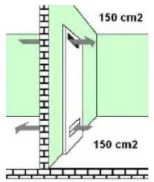
A good ventilation is required in the room for safe operation of your duct. If there is no window or door to be used for ventilation of the n, an additional ventilation system should be installed.

The floor area of the kitchen should be bigger than 8m^2 . Kitchen volume should be bigger than 20m^3 .

The chimney outlet should be at height of 1.80m from the floor and in diameter of 150mm directly opening to the atmosphere.

Air vent should be near the kitchen floor and minimum75cm ^2 , opening to the outer atmosphere


2.2. Installation and connections
2.2.1. Preparation of the built-it range prior to installation

natural_image
Technical line drawing of a mechanical component with multiple slots and mounting holes (no text or symbols)Figure 1

natural_image
Technical line drawing of an electronic device with a coiled cable and labeled 'Figure 1' (no text or symbols on the diagram itself)Figure 2

natural_image
Technical line drawing of a mechanical component with multiple slots and mounting holes (no text or symbols)Figure 3
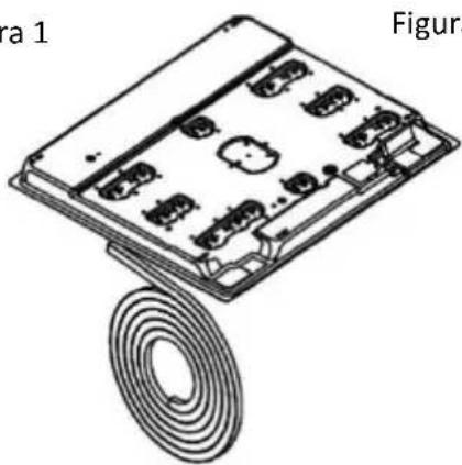
Turn upside down range in the Styrofoam in the package and apply the silicon. In case of inox products, apply the silicon on inox surface, and in case of glass range products apply to the glass surface.
Apply the silicon supplied in the package around the range as shown in the figure.

Figure 4
Mounting legs connection holes.
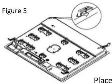
Place the mounting legs as shown in the figure.
Figure 6

- Glass
2.Silicon Seal 6.Silicon Seal - Tray 7. Counter Surface
4.Connection Element 8.Connection Clips

- Upper Tray
9.Screw
2.2.2. Installation of the range

Figure 7

The range is equipped with a seal to prevent the liquids through the cavities into the cabinet. In order to place this seal, adhere the seal as shown in the figures above. Turn the range upside down and remove the protective tape of the rubber seal and adhere it to the range; both ends of the seal should meet each other. Install the mounting sheets as shown in figure 5 by help of screw. And place the range in the opening on the counter.
Figure 7 shows the size to which the counter will be cut for installation of the range. Place the prepared range into the counter cut to these sizes. If you will use the range on the built-in oven, observe the figures 9 and 10 for proper air circulation between the oven and range.
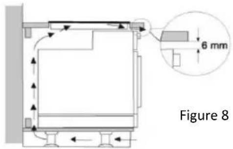

Figure 9

Start to use after you remove the protective film on Inox surface.
2.3. Wiring

You should definitely use an earthed line for the product!
The manufacturing firm shall not be responsible for any damages that may occur if the product is used without the earth.
Electric shock, short-circuit or fire risk arising from the installation performed by any unprofessional persons! The product should be connected to the mains only by an authorized and qualified person and the warranty of the product starts only after correct installation.
Power shock, short-circuit or fire risk arising from damaged power cable! The power cable should be crushed, crinkled or pinched or should not contact with the hot parts of the product. If the power cable gets damaged, it should be replaced by a qualified electrician.
- The mains supply data should be same on the data indicated on the nameplate of the unit. You may find the nameplate at the back of or under the product.
- The connection cable of the product should comply with the technical specifications and power consumption.
Risk of electric shock! Before performing any work on the electric installation, please disconnect the power supply of the product.

2.4. Gas connection

Any work on the gas equipment and systems should be performed by the qualified and authorized persons.
Prior to installation, make sure the conditions of local distribution (gas type and gas pressure) comply with the settings of the product.
2.4.1. LPG connection
Make sure the gas hose and gas pressure-reducing valve you use on the range are safe. Connect the gas delivery hose with the hose behind the range and tighten it by using a clamp and screwdriver (figure 10). Make sure it is firmly tightened.
Gas delivery hose of the equipment should not be longer than 1500mm. The pressure of the pressure-reducing valve to be used for LPG should be 300mmSS and certificated.

Gas delivery hose should not pass through the hot part behind the equipment. Temperature of the gas hose should not exceed 90°C (degree).
Prior to use, make sure the system does not leak any gas.

1- G1/2 Nipple)
2- Silicon seal
3- G1/2 Hose inlet ( gas inlet)
4- Metal clamp
5- Gas hose (inner diameter 8mm)
Figure 10
2.4.2. NG (natural gas) connection
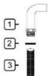
1- G1/2 Nipple)
2- Silicon seal
3- G1/2 NG hose (EN 14800 compliant natural gas hose)
Figure 11
If your equipment is set for natural gas, get the equipment connected by the installation firm of the concerned natural gas distribution
company. Natural gas connection of your equipment is 12 ”. If you desire to convert your equipment from LPG to natural gas or from natural gas to LPG, contact with the nearest service centre and make them do the required gas conversion settings.
2.5. Sealing inspection
Open the pressure-reducing valve or natural gas valve and control by application of much foamy water on the connection to find out any gas leakage.
Never control by flame.
2.6. Final inspection
-
Plug the power cable into the socket and activate the fuse of the equipment.
-
Control the functions.
2.6.1. LPG-NG / NG-LPG conversion
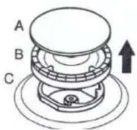
Figure 12

natural_image
Diagram showing a mechanical component with an arrow indicating rotation, no text or symbols presentFigure 12.1
natural_image
Diagram of a mechanical assembly with a bottle and circular base, no text or symbols presentFigure 12.2

natural_image
Technical line drawing of a mechanical component assembly (no text or symbols)Figure 12.3
natural_image
Simple line drawing of a mechanical component with a handle and circular base (no text or symbols)Figure 12.4
Remove the burner cover and burner as shown in in the Figure 12.
Remove the injector by help of 7's socket screwdriver as shown in the Figure 12.1
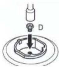
Fix the injector (D) to be converted as shown in the Figure 12.2.
(see table 1).
Replace the burner as shown in the Figure 12.3.
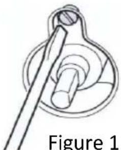
Turn on the burners respectively after conversion and remove the button on the control panel and set the flame length by tightening or loosening the screw on the gas valve (12.4 cock) or in the valve shaft.
2.7. Disposal of the product
2.7.1. Destruction of the package
Packaging materials are dangerous for the children. Keep the packaging materials at a place not accessible by the children.
The packaging of the product is made of the recycled materials. And throw them in the garbage by shorting out as per the instructions on waste. Do not dispose them together with the normal domestic waste.
2.7.2. Future transportation operations
- Keep the product in its original box and carry the product in this box. Comply with the instructions given on the box. If the original cartoon is not available, wrap the product with the blister packaging material or a thick paperboard and tape it firmly.
• Fix the heads and pot supports firmly with a tape.
- Do not put any object on the product. The product should be carried upright.
- Control the general appearance of the product for any damage that might have occurred during transportation.
2.7.3. Disposal of the old product
Dispose the old product in such a way that it will not give damage to the environment.
A mark (WEEE) is present on this product, indicating that the electric and electronic equipment waste should be collected separately. This means that the equipment should be dealt with as per EU Directive 2002/96/EC to recycle or disintegrated into parts for minimising its effect on the environment. For further information, please contact with the local and regional authorities.
The electronic products which are not kept subject to the controlled waste gathering process constitute potential risk for both environment and human health due to the harmful substances they contain.
You may contact with your authorized dealer or the municipal waste collection centre to get information about how you may dispose of the product.
Before you throw the product into the garbage, cut the electrical plug and break the cover lock, if any, in order that the children are not exposed to any risk.
3. ABOUT PRODUCT:
3.1. General view


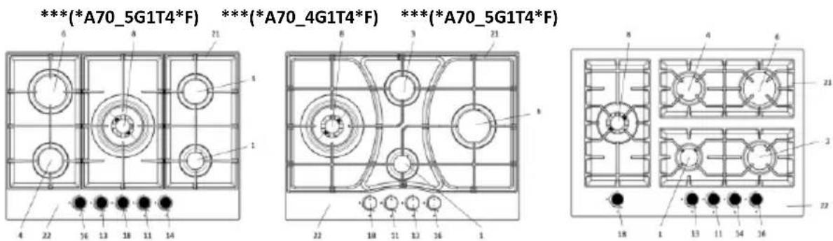
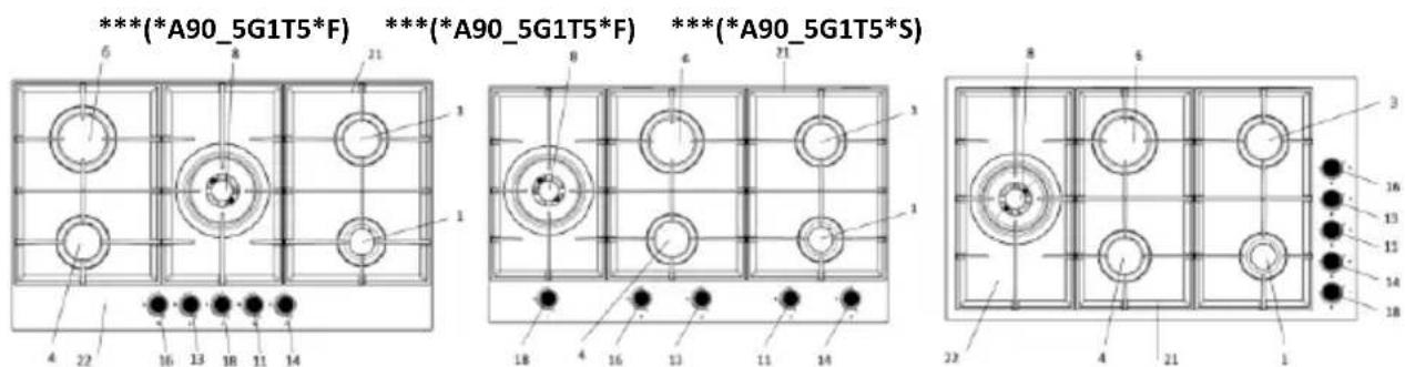

-
Small burner
-
Small burner
-
Medium burner
-
Medium burner
-
Fish burner
-
Big burner
-
Big burner
-
Wok / Mini wok burner
-
Wok / Mini wok burner
-
Wok / Mini wok burner
-
Small burner button No. 1
-
Small burner button No. 2
-
Medium burner button No. 3
-
Medium burner button No. 4
-
Fish burner button No. 5
-
Rapid burner button No. 6
-
Rapid burner button No. 7
-
Wok /Mini wok burner button No. 8
-
Wok /Mini wok burner button No. 9
-
Wok /Mini wok burner button No. 10
-
Pan Supports
-
Range top tray
3.2. Consumption values
Table 1_ Consumption values (for Remay burners)
| LPG G30 - 30 mbar | NG G20 - 20 mbar | LPG G30 - 50 mbar | NG G25.3 - 25 mbar | |||||||||
| Injector (mm) | Power (kW) | Consumption (g/h) | Injector (mm) | Power (kW) | Consumption (m3/h) | Injector (mm) | Power (kW) | Consumption (g/h) | Injector (mm) | Power (kW) | Consumption (m3/h) | |
| Small Burner | ∅0,50 | 1,00 | 73 | ∅0,70 | 1,00 | 0,095 | ∅0,43 | 1,00 | 73 | ∅0,75 | 1,00 | 0,111 |
| Medium Burner | ∅0,72 | 2,00 | 145 | ∅1,03 | 2,00 | 0,190 | ∅0,62 | 2,00 | 145 | ∅1,06 | 2,00 | 0,221 |
| Big Burner | ∅0,85 | 2,90 | 211 | ∅1,24 | 2,90 | 0,276 | ∅0,75 | 2,90 | 211 | ∅1,27 | 2,90 | 0,321 |
| Wok Burner (Defendi) | ∅0,98 | 3,80 | 276 | ∅1,45 | 3,80 | 0,362 | ∅0,98 | 4,70 | 342 | ∅1,40 | 3,80 | 0,421 |
Table 1.1_ Consumption values (for Sabaf burners)
| LPG G30 30 mbar | NG G20 20 mbar | LPG G30 50 mbar | NG G25.3 25 mbar | |||||||||
| Injector (mm) | Power (kW) | Consumption (g/h) | Injector (mm) | Power (kW) | Consumption (m3/h) | Injector (mm) | Power (kW) | Consumption (g/h) | Injector (mm) | Power (kW) | Consumption (m3/h) | |
| Small Burner | 0,50 | 1,00 | 73 | 0,72 | 1,00 | 0,095 | 0,43 | 1,00 | 73 | 0,75 | 1,00 | 0,111 |
| Medium Burner | 0,70 | 2,00 | 145 | 1,03 | 2,00 | 0,190 | 0,62 | 2,00 | 145 | 0,97 | 2,00 | 0,221 |
| Big Burner | 0,85 | 2,90 | 211 | 1,15 | 2,90 | 0,276 | 0,75 | 2,90 | 211 | 1,18 | 2,90 | 0,321 |
| Fish Burner | 0,68 | 1,80 | 131 | 0,94 | 1,80 | 0,171 | 0,59 | 1,80 | 131 | 0,98 | 1,80 | 0,199 |
| Mini Wok | 0,82 | 2,50 | 182 | 1,15 | 2,50 | 0,238 | 0,73 | 2,50 | 182 | 1,15 | 2,30 | 0,255 |
| Wok Burner (3.8 kW) | 1,00 | 3,80 | 276 | 1,50 | 3,80 | 0,362 | 0,78 | 3,80 | 276 | 1,45 | 3,80 | 0,421 |
| Wok Burner (4.2 kW) | 1,03 | 4,20 | 305 | 1,50 | 4,20 | 0,400 | 0,83 | 4,20 | 334 | 1,50 | 4,20 | 0,465 |

The firm may make change in the technical specifications to
improve quality of the product without prior notice.

The figures given in the manual are schematic and may not be
exactly same with your product.

The values given on the markings on the product or in the other
printed documents provided with the product are values obtained under the laboratory conditions as per the applicable standards. These values may vary depending on the use and ambient conditions of the product.
4. USE OF THE RANGE
4.1. First use
Start to use the equipment after removal of the protective film on Inox surface.
4.2. First cleaning

Some detergents or cleaning agents may give harm to the surface.
-
Remove all packaging materials.
-
Wipe the product surface with a damp cloth or sponge and wipe dry with a dry cloth.
4.3. Description of use of the gas range:

1: Push and turn anticlockwise the gas range button for setting high flame.
2: Turn on the lighter depending on the characteristics of your range.
3: Set to the desirged flame position.
4: When the desired cooking operation is over, bring the range button to the top point by turning it clockwise to turn off the burner.

Container size and gas flame should match with each other.
Gas flame should be set in such a way that it should not spread out from the container base.
Put the container as centered on the pot bearer.
4.4. Gas cut-off safety apparatus
natural_image
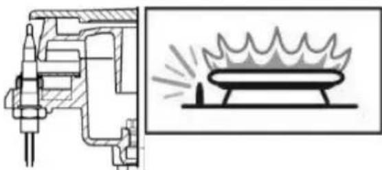
Technical diagram showing a mechanical assembly and its corresponding schematic of a fire extinguisher (no text or labels present)Thermal element activetas the safety mechanism activates and cuts off the gas immediately against extinguishment of the top burners due to liquid overflown.
1: Push and turn anticlockwise the gas range button for setting high flame.
2: Turn on the lighter depending on the characteristics of your range.
3: After it turns on, hold pressed the button for 3-5 seconds and ensure the safety mechanism to activate.
4: If it does not turn on after you push and release the button, repeat the same action by holding the button pressed for 15 seconds.
5: Set to the desired flame position.
6: When the desired cooking is completed, bring the range button to the top point by turning it clockwise to turn off the burner.
5. MAINTENANCE AND CLEANING
5.1. General information
If the product is cleaned regularly, its service life extends and the frequently encountered problems reduce.

Risk of electric shock!
Prior to cleaning, switch off the power of the product to avoid risk of electric shock.

Hot surfaces may cause burns!
Wait for the product to cool down prior to cleaning the product.
- You should clean the product thoroughly after you use it each time. Thus the food remnants are easily cleaned and you prevent these remnants from being burnt when the product is used later on.
- No special cleaning agent is required for cleaning the product. Clean the product by use of dishwashing liquid, lukewarm water and a soft cloth or sponge and wipe clean with a dry cloth.
- Make sure you completely wipe off any liquid left after the cleaning and clean immediately any food around splashed during the cooking.
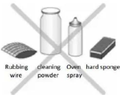
- Do not use any cleaning agent containing acid or chlorine for cleaning the stainless steel or inox surfaces and handle. Clean by wiping in single direction by help of a soft cloth with soap and liquid (non-scratching) detergent.

Some detergents or cleaning agents may give harm to the surface.
Do not use abrasive detergents, cleaning powders/creams or sharp objects.

Do not use steam cleaning agents for cleaning.
5.2. Cleaning the control panel
Clean the control panel and control button with a damp cloth and wipe dry with a dry cloth.

The control panel may get damaged! Do not remove the control button to clean the control panel.
5.3. Cleaning the range
There is no need for any range cleaner or other special cleaning agent to clean the range. It is recommended to qipe the range with a damp cloth when it is stil likewarm.
6. SUGGESTED SOLUTIONS FOR PROBLEMS
Product does not operate.
√ The product is not plugged (earthed) to the socket. Make sure the equipment is plugged.
√ The fuse is burn or broken. Check the fuse in the fuse box. If the fuse is burnt, activate it again.
The product ignites, but does not burn.
√ Gas is over.
√ Cylinder valve or natural gas valve is closed.
√ In case of houses with natural gas supply, if there is gas leakage detector, the leak may be detected and gas cut off.
√ Injector is clogged.
Flame burns low.
√ Cylinder is over.
√ Injector is clogged.
When the product heats and cools down, metallic sounds are heart.
√ Metal parts expand when heated and cause sound. This is not a cause of failure.
If you cannot eliminate the problem although you performed the instructions given in this section, call your service to get support. Never attempt to repair the product that does not operate.
PROCEDURE IN CASE OF FAILURE OF AN INFINITON PRODUCT
Dear customers, to request technical assistance or repair of your Infiniton product, you have our website, operating 24 hours a day and 7 days a week:

Alternatively, if they wish, they can request technical assistance via email:
info@infiniton.es
rma@infiniton.es
To streamline all procedures, the following information should always be indicated:
• Name and surname
- Telephone 1
- Telephone 2
- Full address
- Postal Code
- Population
- Brand
- Product model
- Serial number
- Failure presented by the product
If they wish, they can request technical assistance through the number 958 087 169, available only for white range products (except for free-standing microwaves).
INFINITON
MANUAL DE USO DO FORNO DE GÁS
76AGX51
ean: 8445639001899
78GLN52
ean: 8445639001905
Instalação
natural_image
Isometric technical drawing of a rectangular electronic component with internal slots and mounting holes (no text or symbols)Figura 1

natural_image
Technical line drawing of a mechanical component with coiled spring and labeled 'Figura' (no text or symbols on the diagram itself)Figura 2

natural_image
Technical line drawing of a rectangular electronic component with internal slots and mounting holes (no text or symbols)Figura 3
natural_image
Technical line drawing of a multi-panel electronic device with mounting holes and connectors (no text or symbols)Figura 4
natural_image
Diagram showing a mechanical component with an inset view of a cylindrical part (no text or symbols)Figura 12.1

natural_image
Diagram of a mechanical assembly with a bottle and circular base, no text or symbols presentFigura 12.2

natural_image
Technical line drawing of a mechanical component assembly (no text or symbols)Figura 12.3

natural_image
Diagram of a mechanical component with a tool inserted into a circular housing, labeled 'Figura 12.4' (no other text or symbols)natural_image
Technical diagram showing a mechanical assembly and its corresponding schematic of a fire extinguisher (no text or labels present)- Please first read this manual!
- TABLE OF CONTENTS
- IMPORTANT SAFETY INSTRUCTIONS
- General Safety
- Safety for children
- Safety of the electric-related works
- Intended use
- INSTALLATION
- Prior to use of the product
- Installation and connections
- Preparation of the built-it range prior to installation
- Installation of the range
- Wiring
- You should definitely use an earthed line for the product!
- Gas connection
- LPG connection
- Gas delivery hose should not pass through the hot part behind the equipment. Temperature of the gas hose should not exceed 90°C (degree).
- NG (natural gas) connection
- Sealing inspection
- Final inspection
- LPG-NG / NG-LPG conversion
- Disposal of the product
- Destruction of the package
- Future transportation operations
- Disposal of the old product
- ABOUT PRODUCT:
- General view
- Consumption values
- USE OF THE RANGE
- First use
- First cleaning
- Description of use of the gas range:
- Gas cut-off safety apparatus
- MAINTENANCE AND CLEANING
- General information
- Cleaning the control panel
- Cleaning the range
- SUGGESTED SOLUTIONS FOR PROBLEMS
- PROCEDURE IN CASE OF FAILURE OF AN INFINITON PRODUCT
- INFINITON
- MANUAL DE USO DO FORNO DE GÁS
Brand : Infiniton
Model : 76AGX51
Category : Gas cooktop